EP4015163A1 - Gripping tool - Google Patents
Gripping tool Download PDFInfo
- Publication number
- EP4015163A1 EP4015163A1 EP20214844.1A EP20214844A EP4015163A1 EP 4015163 A1 EP4015163 A1 EP 4015163A1 EP 20214844 A EP20214844 A EP 20214844A EP 4015163 A1 EP4015163 A1 EP 4015163A1
- Authority
- EP
- European Patent Office
- Prior art keywords
- assembly
- gripping tool
- axis
- frame
- support frame
- Prior art date
- Legal status (The legal status is an assumption and is not a legal conclusion. Google has not performed a legal analysis and makes no representation as to the accuracy of the status listed.)
- Granted
Links
Images


Classifications
-
- B—PERFORMING OPERATIONS; TRANSPORTING
- B25—HAND TOOLS; PORTABLE POWER-DRIVEN TOOLS; MANIPULATORS
- B25J—MANIPULATORS; CHAMBERS PROVIDED WITH MANIPULATION DEVICES
- B25J15/00—Gripping heads and other end effectors
- B25J15/0052—Gripping heads and other end effectors multiple gripper units or multiple end effectors
- B25J15/0061—Gripping heads and other end effectors multiple gripper units or multiple end effectors mounted on a modular gripping structure
-
- B—PERFORMING OPERATIONS; TRANSPORTING
- B25—HAND TOOLS; PORTABLE POWER-DRIVEN TOOLS; MANIPULATORS
- B25J—MANIPULATORS; CHAMBERS PROVIDED WITH MANIPULATION DEVICES
- B25J19/00—Accessories fitted to manipulators, e.g. for monitoring, for viewing; Safety devices combined with or specially adapted for use in connection with manipulators
- B25J19/007—Means or methods for designing or fabricating manipulators
Definitions
- the present invention relates to a gripping tool, which can be used by a manipulator device to pick up and manipulate items.
- Gripping tools of the type indicated above are configured to make temporary contact with an object to be gripped, ensuring its position and orientation during handling.
- the grip is obtained by means of forces produced by gripping elements, temporarily ensuring a defined position and orientation of the object to be handled, relative to a reference system.
- a typical example of use is that on a multi-axis manipulator robot, in particular, for picking up and positioning a metal item in a welding station, for assembling a motor-vehicle structure or a sub-assembly thereof.
- Tools of the type indicated above that have been made up to now have a relatively complex structure requiring long and laborious preliminary calibration operations. Conversely, in the event that these preliminary operations do not have to be carried out, the tool is designed to operate only on items of a particular geometry, thus restricting the use of the tool to a certain type of items to be gripped.
- One object of the invention is that of producing a gripping tool having a relatively simple and light structure, which allows preliminary calibration operations to be carried out, in a particularly simple and rapid way.
- An additional object of the invention is to provide a gripping tool of the type indicated above which has a modular structure that can be easily reconfigured according to the item to be handled, the assembly station and the manipulator robot used.
- An additional object of the invention is to provide a gripping tool of the type indicated above that is extremely reliable in use and relatively low in cost.
- the invention relates to a gripping tool, usable on a manipulator device for picking up and handling items, said gripping tool comprising:
- the invention also relates to a method wherein, prior to the use of the tool, a preliminary calibration is performed comprising the following steps:
- reference 1 indicates - in general - a gripping tool ("gripper") according to the invention, usable on a manipulator robot of any known type to pick up and position items in an assembly station.
- the tool 1 according to the invention is of general use and that - in particular - it can be used with any type of manipulating device or machine. Furthermore, the tool according to the invention can be used not only to pick up and position items in a station wherein the picked-up item must be assembled on a previously prepared item in a precise position in the station, but also to pick up and position items in any other type of industrial equipment or even just to transfer items from one station to another in a production plant. In the example illustrated in Figure 1 , the gripping tool 1 picks up a side of a motor-vehicle door.
- the tool 1 comprises a support frame 2 provided with an attachment element 3 for connecting to a manipulator device (not illustrated in the drawings).
- the support frame 2 is tubular in shape, and is mainly spaced along a first axis X.
- the support frame 2 is made of composite material, including a matrix, for example, a matrix of plastic material, reinforced with fibers, for example, carbon fibers.
- the support frame 2 is a tubular member with an elliptical cross-section.
- the term "elliptical" means any cross-section with an oval shape having a main axis and a second minor axis of the main axis.
- the support frame 2 has characteristics of extreme lightness, also being relatively simple to produce and also preventing any type of undesired rotation of the components of the tool 1 constrained to the support frame 2.
- the attachment element 3 is a plate element with two opposite faces, wherein one of the two faces is arranged for connecting to the manipulator device.
- the plate element is mounted on the support frame 2 by means of an anchoring ring 30 fixed on the support frame 2.
- the anchoring ring 30 has a first portion associated with the plate element, and a second portion connected to the first portion by connecting elements of any known type.
- the attachment element 3 and the anchoring ring 30 are made of metal material.
- the gripping tool 1 comprises a plurality of gripping devices 80 distributed in assemblies 8, wherein each assembly 8 consists of one or more gripping devices 80. As illustrated in Figures 1 , 2 , each assembly 8 is carried by a respective auxiliary frame 4 connected to the support frame 2 by means of respective connecting members, which are described in detail in the following description.
- each auxiliary tubular frame 4 is tubular members made in a manner substantially similar to that indicated above for the support frame 2. Therefore, according to a preferred example, each auxiliary tubular frame 4 is made of composite material and has an elliptical cross-section having smaller dimensions than those of the support frame 2.
- each auxiliary frame 4 is attached to the support frame 2 by means of an anchoring ring 5, so that the auxiliary frames 4 are spaced substantially perpendicular to the support frame 2.
- each ring 5 carries a pair of auxiliary frames 4.
- each anchoring ring 5 comprises a first portion 50 and a second portion 51 rigidly connected to each other, so as to be stably mounted on the support frame 2.
- the aforesaid portions 50, 51 are substantially plate-shaped elements having a respective inner face 20, 21 with a rounded shape to allow coupling to the tubular-shaped support frame 2.
- the connection between the portions 50, 51 is made by means of fastening elements of any known type coupled with respective holes 52 made on the portions 50, 51.
- the first portion 50 has a series of cavities 11 and a central hole 13, to allow connection of the auxiliary frame 4 to the respective ring 5.
- each ring 5 carries a pair of auxiliary frames 4 ( Figures 1 , 2 )
- the first and second portions 50, 51 are made in the same way and carry both the aforesaid cavities 11 and the aforesaid central hole 13.
- the second portion 51 can be produced as a simple counterpart of the portion 50 ( Figure 7 ), so as to create a stable mounting on the support frame 2.
- the rings 5 are configured to be adjustable in position along the support frame 2 (along the first axis X). It will, therefore, be appreciated that the gripping tool 1 according to the invention allows a first calibration operation to be carried out prior to use, by adjusting the anchoring rings 5 and 30 along the support frame 2 (axis X). As evident, to carry out this operation, it is necessary to remove the connecting elements that hold the portions of each ring together, and to position the rings along the frame 2 in the chosen position.
- the connecting members designed to connect the auxiliary frames 4 to the support frame 2 also comprise a respective angular bracket 6 (illustrated in the enlarged scale view of Figure 3A ).
- Each angular bracket 6 comprises a base portion 60 coupled to a respective anchoring ring 5, and a vertical portion 61 tightened to a respective auxiliary frame 4.
- the tool 1 allows a second preliminary calibration operation.
- This second operation consists in adjusting, in a determined position, each auxiliary frame 4 with respect to the aforesaid vertical portion 61 of the bracket 6, by rotating the frame 4 around an axis Y perpendicular to the plane defined by the aforesaid vertical portion 61 of the angular bracket 6.
- the vertical portion 61 comprises a central opening 15 and a plurality of holes 14 arranged radially around the central opening 15.
- Each auxiliary frame 4 is tightened to the respective bracket 6 with the aid of a flange 10 ( Figure 3B ) substantially arranged at one end of the respective auxiliary frame 4.
- the flanges 10 are defined by two portions 18, 19 connected to each other, around the respective auxiliary frame 4.
- the portions 18, 19 have a respective rounded face 22, 23 to allow assembly on the respective auxiliary frame 4 of tubular shape.
- each flange 10 is configured to perform a quick and correct centering on the vertical portion 61 of the bracket 6.
- the flange 10 comprises a central projecting portion 17, and a series of connecting holes 16 arranged radially around the central projecting portion 17.
- the central opening 15 of the vertical portion 61 is formed to receive the central protruding portion 17 of the connecting flange 10.
- Each flange 10 is connected to the respective bracket 6 by means of fastening elements 20 engaged in respective holes 14, 16, respectively aligned.
- connection is ensured by respective fastening members 20 that engage four pairs of holes 14, 16 respectively aligned with each other.
- the tool 1 allows a second calibration operation prior to use, which can be carried out by adjusting each auxiliary frame 4 in a determined position with respect to the aforesaid vertical portion 61 of the bracket 6, by rotating the frame 4 around an axis Y perpendicular to the plane defined by the aforesaid vertical portion 61 of the angular bracket 6.
- the base portion 60 of a respective angular bracket 6 is coupled to a respective anchoring ring 5.
- the coupling can be achieved by means of a connecting element (for example, a plate-shaped element).
- this coupling is achieved by means of a controlled failure assembly 7, which is not per se the subject of the present invention, illustrated - in particular - in the enlarged scale views of Figures 5, 6 .
- the controlled failure assembly 7 is configured to ensure that, in the event of a collision, the gripping tool 1 breaks in a precise point (pin 70), favoring the subsequent repair of the components, in order to reduce the overall repair time.
- a central hole 62 and a series of auxiliary holes 62 arranged radially around the central hole 62 are formed on the base portion 60 of the angular bracket 6 ( Figure 3A ).
- the base portion 60 is triangular in shape, on which three auxiliary holes 62 are made, each arranged at a vertex of the triangular shape.
- the controlled failure assembly 7 comprises a threaded tubular pin 70 passing through the central hole 62 obtained on the base portion 60 of the bracket 6, and screwed to the main hole 13 obtained on a respective anchoring ring 5. As illustrated in Figure 5 , a part of the pin 70 protrudes from the base portion 60, in the opposite direction with respect to the ring 5.
- the assembly 7 also includes a threaded clamping bushing 71, axially engaged on the tubular pin 70, in particular on its part that protrudes from the base portion 60, in the opposite direction with respect to the ring 5.
- the bushing 71 is arranged against the base portion 60 of the angular bracket 6, and comprises an end portion coupled to the central hole 62 of the bracket 6.
- the assembly 7 also comprises additional fastening elements 72 arranged radially around the main axis of the pin 70 and of the bushing 71.
- Each fastening element 72 comprises a threaded part at a first end, engaged with the holes 63 of the angular bracket 6 and a ball connecting element 26 at a second end, engaged within one of the spherical cavities 11 obtained on a respective anchoring ring 5.
- each controlled failure assembly 7 can be mounted to an anchoring ring 5, so as to be adjustable in position, with respect to the anchoring ring. This adjustment can be made by rotating the assembly 7 (and the bracket 6 associated therewith) around an axis perpendicular to the axis X of the frame 2, passing through the plane defined by the portion of the ring 5 on which the assembly 7 is mounted. To produce the assembly, each hole 63 of the angular bracket 6 must be axially aligned with a respective spherical cavity 11.
- the gripping tool 1 allows an additional calibration operation to be carried out prior to use, by adjusting the assembly 7 and the bracket 6, around an axis perpendicular to the axis X of the frame 2, passing through the plane defined by the ring portion 5 on which the assembly 7 is mounted.
- the gripping tool 1 may comprise, in addition to the gripping devices 80, further devices 9 designed to perform additional functions with respect to those performed by the gripping devices 80.
- these further devices 9 comprise a reference pin 90, useful for referring the item into position during the picking-up and handling step carried out by the gripping devices 80.
- These devices 9 are arranged at a terminal end of a respective frame 24, in turn connected to a respective anchoring ring 5'.
- the anchoring rings 5' are made in a manner similar to that previously described for the rings 5 connected to the auxiliary frames 4.
- the connection between each ring 5' and the respective frame 24 is made by means of a controlled failure assembly 7.
- the frame 24 is a beam-shaped element that extends substantially transversely to the support frame 2.
- the end portion of the frame 24 has a series of holes and a central opening (similar to that provided on the base portions 60 of the brackets 6) to create the connection with the assembly 7. Therefore, in this case, the assembly 7 connects the frame 24 to the ring 5', without the aid of the previously described angular bracket 6.
- Figures 8A, 8B illustrate an additional calibration operation, which can be carried out prior to use, wherein the assembly 7 and the respective frame 24 can be mounted in an adjustable position, by rotating the assembly 7 and the frame 24 around an axis perpendicular to the axis X of the frame 2, passing through the plane defined by the portion of the ring 5' on which the assembly 7 is mounted.
- FIGS 9, 10 are enlarged-scale views illustrating preferred embodiments of the gripping devices 80.
- the gripping devices 80 of each assembly 8 are made at least partially by means of an additive manufacturing technology.
- additive manufacturing has also been used for some time. It makes use of an energy source, such as, for example, a laser beam, to melt layers of powders of synthetic material or metal material in such a way as to form - layer by layer - a component with a required configuration.
- an energy source such as, for example, a laser beam
- a machine for producing metal components by means of “additive manufacturing” technology is, for example, described and illustrated in document WO2015/181772 A1 .
- Each assembly 8 comprises a plurality of arms 81 on which at least one connecting block 25 is mounted for connecting support devices 83 arranged to support the gripping devices 80 (shaped, for example, as grippers), made to grip the sheet metal items.
- the aforesaid plurality of arms 81 of each assembly 8 extends from a connecting flange 12 connected to a terminal end of a respective auxiliary frame 4.
- the aforesaid plurality of arms 81 and the connecting blocks 25 are a monolithic assembly made by means of an additive manufacturing technology, while the connecting flange 12 is made, for example, of metal material by means of traditional molding technologies.
- the arrangement and number of the arms 81 may vary between the assemblies 8, so that the arms 81 of each assembly 8 are suitably configured to support a certain gripping member and/or in relation to the position with respect to the item to be gripped and/or the shape and weight of the item to be gripped.
- the arms 81 are suitably made quickly, diversifying each assembly 8, according to the envisaged needs. Therefore, the gripping tool 1 is easily reconfigurable, by modifying the arms 81 in a simple and rapid way to meet the necessary requirements of strength, rigidity and reliability. Furthermore, this advantage of being able to reconfigure the gripping tool according to the production needs is further increased thanks to the possibility of being able to carry out the preliminary calibration operations indicated above.
Landscapes
- Engineering & Computer Science (AREA)
- Robotics (AREA)
- Mechanical Engineering (AREA)
- Manipulator (AREA)
Abstract
Description
- The present invention relates to a gripping tool, which can be used by a manipulator device to pick up and manipulate items.
- Gripping tools of the type indicated above are configured to make temporary contact with an object to be gripped, ensuring its position and orientation during handling. The grip is obtained by means of forces produced by gripping elements, temporarily ensuring a defined position and orientation of the object to be handled, relative to a reference system.
- A typical example of use is that on a multi-axis manipulator robot, in particular, for picking up and positioning a metal item in a welding station, for assembling a motor-vehicle structure or a sub-assembly thereof.
- Tools of the type indicated above that have been made up to now have a relatively complex structure requiring long and laborious preliminary calibration operations. Conversely, in the event that these preliminary operations do not have to be carried out, the tool is designed to operate only on items of a particular geometry, thus restricting the use of the tool to a certain type of items to be gripped.
- One object of the invention is that of producing a gripping tool having a relatively simple and light structure, which allows preliminary calibration operations to be carried out, in a particularly simple and rapid way.
- An additional object of the invention is to provide a gripping tool of the type indicated above which has a modular structure that can be easily reconfigured according to the item to be handled, the assembly station and the manipulator robot used.
- An additional object of the invention is to provide a gripping tool of the type indicated above that is extremely reliable in use and relatively low in cost.
- In order to achieve one or more of the aforesaid objects, the invention relates to a gripping tool, usable on a manipulator device for picking up and handling items, said gripping tool comprising:
- a support frame extending along a first axis, provided with an attachment element for connecting to the manipulator device,
- a plurality of gripping devices distributed in assemblies, each assembly consisting of one or more gripping devices,
- wherein each assembly is carried by a respective auxiliary frame connected to the support frame by means of respective connecting members configured to be able to adjust the auxiliary frames and the gripping devices in position with respect to the support frame,
- wherein said respective connecting members comprise an anchoring ring attached to the support frame, so as to be adjustable in position along said first axis,
- wherein said respective connecting members further comprise an angular bracket comprising:
- a base portion coupled to a respective anchoring ring, and a vertical portion mounted to a respective auxiliary frame, in such a way as to be able to adjust each auxiliary frame in a given position, with respect to said vertical portion, by rotating the frame around an axis perpendicular to the plane defined by the aforesaid vertical portion of the angular bracket,
- wherein the gripping devices of each assembly are made - at least partially - by means of an additive manufacturing technology.
- Additional advantageous characteristics of the invention are indicated in the attached claims, which form an integral part of the technical disclosure administered herein in relation to the invention.
- The invention also relates to a method wherein, prior to the use of the tool, a preliminary calibration is performed comprising the following steps:
- adjusting the anchoring rings in position along the axis of the support frame,
- adjusting each auxiliary frame in position with respect to said vertical portion, by rotating the auxiliary frame about an axis perpendicular to the plane defined by the aforesaid vertical portion of the angular bracket, and
- adjusting each pair of connecting elements and angular brackets in position with respect to the anchoring ring, by rotating the connecting element and the bracket associated therewith, around an axis perpendicular to the axis of the support frame, passing through the plane defined by a portion of the ring on which the connecting element is mounted.
- Further characteristics and advantages of the invention will become apparent from the description that follows with reference to the attached drawings, provided purely by way of non-limiting example, wherein:
-
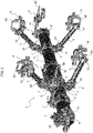
Figure 1 is a perspective view showing a preferred embodiment of a gripping tool according to the invention, associated with a side of a motor-vehicle, -
Figure 2 is an additional perspective view of the gripping tool of the previous figure, in which the motor-vehicle side has been removed, and -
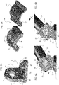
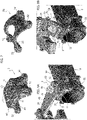
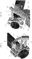
Figures 3-10 are schematic perspective views on an enlarged scale illustrating various components of the tool of the previous figure. - With reference to
Figures 1 and2 , reference 1 indicates - in general - a gripping tool ("gripper") according to the invention, usable on a manipulator robot of any known type to pick up and position items in an assembly station. - It is evident that the tool 1 according to the invention is of general use and that - in particular - it can be used with any type of manipulating device or machine. Furthermore, the tool according to the invention can be used not only to pick up and position items in a station wherein the picked-up item must be assembled on a previously prepared item in a precise position in the station, but also to pick up and position items in any other type of industrial equipment or even just to transfer items from one station to another in a production plant. In the example illustrated in
Figure 1 , the gripping tool 1 picks up a side of a motor-vehicle door. - As illustrated in
Figures 1 and2 , the tool 1 comprises asupport frame 2 provided with anattachment element 3 for connecting to a manipulator device (not illustrated in the drawings). In one or more embodiments, as well as in the one illustrated in the figures, thesupport frame 2 is tubular in shape, and is mainly spaced along a first axis X. Preferably, thesupport frame 2 is made of composite material, including a matrix, for example, a matrix of plastic material, reinforced with fibers, for example, carbon fibers. Still according to an additional preferred characteristic, thesupport frame 2 is a tubular member with an elliptical cross-section. The term "elliptical" means any cross-section with an oval shape having a main axis and a second minor axis of the main axis. - Thanks to these characteristics, the
support frame 2 has characteristics of extreme lightness, also being relatively simple to produce and also preventing any type of undesired rotation of the components of the tool 1 constrained to thesupport frame 2. - In one or more embodiments, as well as in the one illustrated in
Figures 1 ,2 , theattachment element 3 is a plate element with two opposite faces, wherein one of the two faces is arranged for connecting to the manipulator device. The plate element is mounted on thesupport frame 2 by means of ananchoring ring 30 fixed on thesupport frame 2. In accordance with what is illustrated in the drawings, theanchoring ring 30 has a first portion associated with the plate element, and a second portion connected to the first portion by connecting elements of any known type. Preferably, theattachment element 3 and theanchoring ring 30 are made of metal material. - According to an essential characteristic of the present invention, the gripping tool 1 comprises a plurality of
gripping devices 80 distributed inassemblies 8, wherein eachassembly 8 consists of one or moregripping devices 80. As illustrated inFigures 1 ,2 , eachassembly 8 is carried by a respectiveauxiliary frame 4 connected to thesupport frame 2 by means of respective connecting members, which are described in detail in the following description. - In one or more embodiments, as well as in the one illustrated in
Figures 1 ,2 , theauxiliary frames 4 are tubular members made in a manner substantially similar to that indicated above for thesupport frame 2. Therefore, according to a preferred example, each auxiliarytubular frame 4 is made of composite material and has an elliptical cross-section having smaller dimensions than those of thesupport frame 2. - Each
auxiliary frame 4 is attached to thesupport frame 2 by means of ananchoring ring 5, so that theauxiliary frames 4 are spaced substantially perpendicular to thesupport frame 2. In one or more embodiments, as well as in the one illustrated in the drawings, eachring 5 carries a pair ofauxiliary frames 4. - As also illustrated in the enlarged-scale exploded view of
Figure 7 , eachanchoring ring 5 comprises afirst portion 50 and asecond portion 51 rigidly connected to each other, so as to be stably mounted on thesupport frame 2. Preferably, theaforesaid portions inner face shaped support frame 2. The connection between theportions respective holes 52 made on theportions - As will be further explained below, the
first portion 50 has a series ofcavities 11 and acentral hole 13, to allow connection of theauxiliary frame 4 to therespective ring 5. In the case wherein eachring 5 carries a pair of auxiliary frames 4 (Figures 1 ,2 ), the first andsecond portions aforesaid cavities 11 and the aforesaidcentral hole 13. Conversely, in the case wherein eachring 5 carries only oneauxiliary frame 4, thesecond portion 51 can be produced as a simple counterpart of the portion 50 (Figure 7 ), so as to create a stable mounting on thesupport frame 2. - In accordance with an important characteristic of the invention, the
rings 5 are configured to be adjustable in position along the support frame 2 (along the first axis X). It will, therefore, be appreciated that the gripping tool 1 according to the invention allows a first calibration operation to be carried out prior to use, by adjusting theanchoring rings frame 2 in the chosen position. - In accordance with an additional relevant characteristic of the invention, the connecting members designed to connect the
auxiliary frames 4 to thesupport frame 2 also comprise a respective angular bracket 6 (illustrated in the enlarged scale view ofFigure 3A ). Eachangular bracket 6 comprises abase portion 60 coupled to arespective anchoring ring 5, and avertical portion 61 tightened to a respectiveauxiliary frame 4. - In accordance with an additional characteristic of the invention, the tool 1 allows a second preliminary calibration operation. This second operation consists in adjusting, in a determined position, each
auxiliary frame 4 with respect to the aforesaidvertical portion 61 of thebracket 6, by rotating theframe 4 around an axis Y perpendicular to the plane defined by the aforesaidvertical portion 61 of theangular bracket 6. - In accordance with the preferred embodiment illustrated in the drawings, the
vertical portion 61 comprises acentral opening 15 and a plurality ofholes 14 arranged radially around thecentral opening 15. Eachauxiliary frame 4 is tightened to therespective bracket 6 with the aid of a flange 10 (Figure 3B ) substantially arranged at one end of the respectiveauxiliary frame 4. Preferably, theflanges 10 are defined by twoportions auxiliary frame 4. Theportions rounded face auxiliary frame 4 of tubular shape. - As illustrated in
Figures 3A-4B , eachflange 10 is configured to perform a quick and correct centering on thevertical portion 61 of thebracket 6. To make the connection with the bracket 6 (vertical portion 61), theflange 10 comprises a central projectingportion 17, and a series of connectingholes 16 arranged radially around the central projectingportion 17. Thecentral opening 15 of thevertical portion 61 is formed to receive the central protrudingportion 17 of the connectingflange 10. Eachflange 10 is connected to therespective bracket 6 by means offastening elements 20 engaged inrespective holes - Note that the connecting
holes 16 of theflange 10 are offset from that of theholes 14 of thebracket 6. Therefore, by rotating theauxiliary frame 4 around an axis Y perpendicular to the plane defined by thevertical portion 61, it is possible to define the required connecting position between thebracket 6 and theflange 10. In accordance with the preferred embodiment illustrated inFigures 4A, 4B , the connection is ensured byrespective fastening members 20 that engage four pairs ofholes - As illustrated in
Figures 4A, 4B , it will therefore be appreciated that the tool 1 allows a second calibration operation prior to use, which can be carried out by adjusting eachauxiliary frame 4 in a determined position with respect to the aforesaidvertical portion 61 of thebracket 6, by rotating theframe 4 around an axis Y perpendicular to the plane defined by the aforesaidvertical portion 61 of theangular bracket 6. - As previously indicated, the
base portion 60 of a respectiveangular bracket 6 is coupled to arespective anchoring ring 5. The coupling can be achieved by means of a connecting element (for example, a plate-shaped element). According to a preferred characteristic of the invention, this coupling is achieved by means of a controlledfailure assembly 7, which is not per se the subject of the present invention, illustrated - in particular - in the enlarged scale views ofFigures 5, 6 . The controlledfailure assembly 7 is configured to ensure that, in the event of a collision, the gripping tool 1 breaks in a precise point (pin 70), favoring the subsequent repair of the components, in order to reduce the overall repair time. - In order to be able to mount the controlled
failure assembly 7, acentral hole 62 and a series ofauxiliary holes 62 arranged radially around thecentral hole 62 are formed on thebase portion 60 of the angular bracket 6 (Figure 3A ). Preferably, thebase portion 60 is triangular in shape, on which threeauxiliary holes 62 are made, each arranged at a vertex of the triangular shape. - As illustrated in
Figures 5, 6 , the controlledfailure assembly 7 comprises a threadedtubular pin 70 passing through thecentral hole 62 obtained on thebase portion 60 of thebracket 6, and screwed to themain hole 13 obtained on arespective anchoring ring 5. As illustrated inFigure 5 , a part of thepin 70 protrudes from thebase portion 60, in the opposite direction with respect to thering 5. Theassembly 7 also includes a threadedclamping bushing 71, axially engaged on thetubular pin 70, in particular on its part that protrudes from thebase portion 60, in the opposite direction with respect to thering 5. Thebushing 71 is arranged against thebase portion 60 of theangular bracket 6, and comprises an end portion coupled to thecentral hole 62 of thebracket 6. Theassembly 7 also comprisesadditional fastening elements 72 arranged radially around the main axis of thepin 70 and of thebushing 71. Eachfastening element 72 comprises a threaded part at a first end, engaged with theholes 63 of theangular bracket 6 and aball connecting element 26 at a second end, engaged within one of thespherical cavities 11 obtained on arespective anchoring ring 5. - According to an additional characteristic of the invention, each controlled
failure assembly 7 can be mounted to ananchoring ring 5, so as to be adjustable in position, with respect to the anchoring ring. This adjustment can be made by rotating the assembly 7 (and thebracket 6 associated therewith) around an axis perpendicular to the axis X of theframe 2, passing through the plane defined by the portion of thering 5 on which theassembly 7 is mounted. To produce the assembly, eachhole 63 of theangular bracket 6 must be axially aligned with a respectivespherical cavity 11. It will, therefore, be appreciated that the gripping tool 1 according to the invention allows an additional calibration operation to be carried out prior to use, by adjusting theassembly 7 and thebracket 6, around an axis perpendicular to the axis X of theframe 2, passing through the plane defined by thering portion 5 on which theassembly 7 is mounted. - As illustrated in the perspective view of
Figures 1 ,2 , the gripping tool 1 may comprise, in addition to thegripping devices 80,further devices 9 designed to perform additional functions with respect to those performed by thegripping devices 80. In one or more embodiments, as well as in the one illustrated in the drawings, thesefurther devices 9 comprise areference pin 90, useful for referring the item into position during the picking-up and handling step carried out by thegripping devices 80. (Thesedevices 9 are arranged at a terminal end of arespective frame 24, in turn connected to a respective anchoring ring 5'. The anchoring rings 5' are made in a manner similar to that previously described for therings 5 connected to the auxiliary frames 4. The connection between each ring 5' and therespective frame 24 is made by means of a controlledfailure assembly 7. In a preferred example, theframe 24 is a beam-shaped element that extends substantially transversely to thesupport frame 2. In this case, as illustrated inFigures 8A , the end portion of theframe 24 has a series of holes and a central opening (similar to that provided on thebase portions 60 of the brackets 6) to create the connection with theassembly 7. Therefore, in this case, theassembly 7 connects theframe 24 to the ring 5', without the aid of the previously describedangular bracket 6. -
Figures 8A, 8B illustrate an additional calibration operation, which can be carried out prior to use, wherein theassembly 7 and therespective frame 24 can be mounted in an adjustable position, by rotating theassembly 7 and theframe 24 around an axis perpendicular to the axis X of theframe 2, passing through the plane defined by the portion of the ring 5' on which theassembly 7 is mounted. -
Figures 9, 10 are enlarged-scale views illustrating preferred embodiments of thegripping devices 80. According to an important characteristic of the invention, thegripping devices 80 of eachassembly 8 are made at least partially by means of an additive manufacturing technology. - The technology of "additive manufacturing" has also been used for some time. It makes use of an energy source, such as, for example, a laser beam, to melt layers of powders of synthetic material or metal material in such a way as to form - layer by layer - a component with a required configuration. A machine for producing metal components by means of "additive manufacturing" technology is, for example, described and illustrated in document
WO2015/181772 A1 . - Each
assembly 8 comprises a plurality ofarms 81 on which at least one connectingblock 25 is mounted for connectingsupport devices 83 arranged to support the gripping devices 80 (shaped, for example, as grippers), made to grip the sheet metal items. The aforesaid plurality ofarms 81 of eachassembly 8 extends from a connectingflange 12 connected to a terminal end of a respectiveauxiliary frame 4. - According to a characteristic of the invention, for each
assembly 8, the aforesaid plurality ofarms 81 and the connectingblocks 25 are a monolithic assembly made by means of an additive manufacturing technology, while the connectingflange 12 is made, for example, of metal material by means of traditional molding technologies. - The arrangement and number of the
arms 81 may vary between theassemblies 8, so that thearms 81 of eachassembly 8 are suitably configured to support a certain gripping member and/or in relation to the position with respect to the item to be gripped and/or the shape and weight of the item to be gripped. - By means of the aforesaid additive manufacturing technology, the
arms 81 are suitably made quickly, diversifying eachassembly 8, according to the envisaged needs. Therefore, the gripping tool 1 is easily reconfigurable, by modifying thearms 81 in a simple and rapid way to meet the necessary requirements of strength, rigidity and reliability. Furthermore, this advantage of being able to reconfigure the gripping tool according to the production needs is further increased thanks to the possibility of being able to carry out the preliminary calibration operations indicated above. - Of course, without prejudice to the principle of the invention, the embodiments and construction details may widely vary with respect to those described and illustrated by way of example, without thereby departing from the scope of the present invention, as defined in the attached claims.
Claims (9)
- A gripping tool (1), usable on a manipulator device for picking up and handling items, said gripping tool (1) comprising:- a support frame (2) extending along a first axis (X), provided with an attachment element (3) for connecting to the manipulator device,- a plurality of gripping devices (80) distributed in assemblies (8), each assembly (8) consisting of one or more gripping devices (80),- wherein each assembly (8) is carried by a respective auxiliary frame (4) connected to the support frame (2) by means of respective connecting members (5, 6, 7) configured to be able to adjust the auxiliary frames (4) and the gripping devices (80) in position with respect to the support frame (2),- wherein said respective connecting members comprise an anchoring ring (5) attached to the support frame (2), so as to be adjustable in position along said first axis (X),- wherein said respective connecting members also comprise an angular bracket (6) comprising:- a base portion (60) coupled to a respective anchoring ring (5), by means of a connecting element, and a vertical portion (61) mounted to a respective auxiliary frame (4), in such a way as to be able to adjust each auxiliary frame (4) in a given position with respect to said vertical portion (61), by rotating the frame (4) around an axis (Y) perpendicular to the plane defined by the aforesaid vertical portion (61) of the angular bracket (6),- wherein the gripping devices (80) of each assembly (8) are made at least partially by means of an additive manufacturing technology.
- A gripping tool (1) according to claim 1, wherein each pair of connecting elements and angular brackets (6) is adjustable in position with respect to the anchoring ring (5), by rotating the connecting element and the bracket (6) associated therewith, around an axis perpendicular to the axis (X) of the frame (2), passing through the plane defined by a portion of the ring (5) on which said connecting element is mounted.
- A gripping tool (1) according to claim 1, wherein said support frame (2) is a tubular member with an elliptical cross-section, made of composite material, including a matrix, for example, a matrix of plastic material, reinforced with fibers, for example, carbon fibers.
- A gripping tool (1) according to claim 1, wherein the gripping devices (80) of each assembly (8) comprise a plurality of arms (81) on which at least one connecting block (25) is mounted for connecting support devices (83) arranged to support the gripping devices (80), said plurality of arms (81) of each assembly (8) extending from a connecting flange (12) connected to a terminal end of a respective auxiliary frame (4).
- A gripping tool (1) according to claim 4, wherein said plurality of arms (81) and said at least one connecting block (25) are made by means of an additive manufacturing technology.
- A gripping tool (1) according to claim 1, wherein said auxiliary frames (4) are tubular members made of composite material, having an elliptical-shaped cross-section.
- A gripping tool (1) according to claim 1, wherein each anchoring ring (5) carries a pair of auxiliary frames (4).
- A gripping tool (1) according to claim 1, wherein each anchoring ring (5) comprises a first portion (50) and a second portion (51) rigidly connected to each other, wherein at least the first portion (50) has a series of cavities (11) and a central hole (13), to allow connection of the respective auxiliary frame (4) by means of said connecting element.
- A method for using a gripping tool (1) according to claim 1, wherein the gripping tool (1) is associated with a manipulator device, and is used to pick up an item and to position it in a correct assembly position above a fixed apparatus of an assembly station,- wherein, prior to the use of the tool (1), a preliminary calibration is performed comprising the following steps:- adjusting the anchoring rings (5) in position along the axis (X) of the support frame (2),- adjusting each auxiliary frame (4) in position with respect to said vertical portion (61), by rotating the auxiliary frame (4) about an axis (Y) perpendicular to the plane defined by said vertical portion (61) of the angular bracket (6), and- adjusting each pair of connecting elements and angular brackets (6) in position with respect to the anchoring ring (5), by rotating the connecting element and the bracket (6) associated therewith around an axis perpendicular to the axis (X) of the support frame (2), passing through the plane defined by a portion of the ring (5) on which the connecting element is mounted.
Priority Applications (3)
| Application Number | Priority Date | Filing Date | Title |
|---|---|---|---|
| EP20214844.1A EP4015163B1 (en) | 2020-12-17 | 2020-12-17 | Gripping tool |
| BR102021023064-9A BR102021023064A2 (en) | 2020-12-17 | 2021-11-17 | GRAPPING TOOL |
| US17/552,452 US11992937B2 (en) | 2020-12-17 | 2021-12-16 | Gripping tool usable on a manipulator device |
Applications Claiming Priority (1)
| Application Number | Priority Date | Filing Date | Title |
|---|---|---|---|
| EP20214844.1A EP4015163B1 (en) | 2020-12-17 | 2020-12-17 | Gripping tool |
Publications (2)
| Publication Number | Publication Date |
|---|---|
| EP4015163A1 true EP4015163A1 (en) | 2022-06-22 |
| EP4015163B1 EP4015163B1 (en) | 2024-02-07 |
Family
ID=74129925
Family Applications (1)
| Application Number | Title | Priority Date | Filing Date |
|---|---|---|---|
| EP20214844.1A Active EP4015163B1 (en) | 2020-12-17 | 2020-12-17 | Gripping tool |
Country Status (3)
| Country | Link |
|---|---|
| US (1) | US11992937B2 (en) |
| EP (1) | EP4015163B1 (en) |
| BR (1) | BR102021023064A2 (en) |
Citations (5)
| Publication number | Priority date | Publication date | Assignee | Title |
|---|---|---|---|---|
| US20060291951A1 (en) * | 2005-06-16 | 2006-12-28 | Norgren Automotive, Inc. | Multi-axis coupling apparatus for adjustably mounting modular tooling members |
| WO2015181772A1 (en) | 2014-05-30 | 2015-12-03 | Prima Industrie S.P.A. | Laser operating machine for additive manufacturing by laser sintering and corresponding method |
| EP3106678A1 (en) * | 2015-06-15 | 2016-12-21 | C.R.F. Società Consortile per Azioni | A joint for constructions |
| DE102016108956A1 (en) * | 2016-05-13 | 2017-11-16 | Deutsches Zentrum für Luft- und Raumfahrt e.V. | Effector for recording, handling and / or dropping objects |
| US20200070363A1 (en) * | 2018-08-30 | 2020-03-05 | Compagnie Plastic Omnium | Gripper of Bodywork Parts |
Family Cites Families (9)
| Publication number | Priority date | Publication date | Assignee | Title |
|---|---|---|---|---|
| WO2004110705A1 (en) * | 2003-06-17 | 2004-12-23 | Kuka Schweissanlagen Gmbh | Manipulator-guided gripping device having a deflection safety device that can prevent collisions |
| US8108978B2 (en) * | 2005-07-06 | 2012-02-07 | Norgren Automation Solutions, Inc. | Apparatus for accurately positioning and supporting modular tooling |
| US20080226427A1 (en) * | 2005-07-06 | 2008-09-18 | Norgren Automotive, Inc. | Apparatus for accurately positioning and supporting modular tooling |
| US8600174B2 (en) * | 2005-09-28 | 2013-12-03 | Facedouble, Inc. | Method and system for attaching a metatag to a digital image |
| KR101048145B1 (en) * | 2009-12-04 | 2011-07-08 | 기아자동차주식회사 | Door Gripper |
| KR101172308B1 (en) * | 2010-09-06 | 2012-08-07 | 현대자동차주식회사 | Gripper for door of vehicle |
| US9808933B2 (en) * | 2015-04-03 | 2017-11-07 | GM Global Technology Operations LLC | Robotic system with reconfigurable end-effector assembly |
| US10112666B2 (en) * | 2015-08-19 | 2018-10-30 | GM Global Technology Operations LLC | Part holding assembly, an assembly system and a method of locating and securing a part |
| JP7171467B2 (en) * | 2019-02-19 | 2022-11-15 | トヨタ自動車九州株式会社 | SUPPORT DEVICE FOR PARTS HOLDER AND VEHICLE DOOR REMOVAL DEVICE |
-
2020
- 2020-12-17 EP EP20214844.1A patent/EP4015163B1/en active Active
-
2021
- 2021-11-17 BR BR102021023064-9A patent/BR102021023064A2/en unknown
- 2021-12-16 US US17/552,452 patent/US11992937B2/en active Active
Patent Citations (5)
| Publication number | Priority date | Publication date | Assignee | Title |
|---|---|---|---|---|
| US20060291951A1 (en) * | 2005-06-16 | 2006-12-28 | Norgren Automotive, Inc. | Multi-axis coupling apparatus for adjustably mounting modular tooling members |
| WO2015181772A1 (en) | 2014-05-30 | 2015-12-03 | Prima Industrie S.P.A. | Laser operating machine for additive manufacturing by laser sintering and corresponding method |
| EP3106678A1 (en) * | 2015-06-15 | 2016-12-21 | C.R.F. Società Consortile per Azioni | A joint for constructions |
| DE102016108956A1 (en) * | 2016-05-13 | 2017-11-16 | Deutsches Zentrum für Luft- und Raumfahrt e.V. | Effector for recording, handling and / or dropping objects |
| US20200070363A1 (en) * | 2018-08-30 | 2020-03-05 | Compagnie Plastic Omnium | Gripper of Bodywork Parts |
Also Published As
| Publication number | Publication date |
|---|---|
| US11992937B2 (en) | 2024-05-28 |
| US20220193923A1 (en) | 2022-06-23 |
| EP4015163B1 (en) | 2024-02-07 |
| BR102021023064A2 (en) | 2022-07-05 |
Similar Documents
| Publication | Publication Date | Title |
|---|---|---|
| EP1878543B1 (en) | Geometric end effector system | |
| EP4072796B1 (en) | A gripping tool which can be used by a manipulator device for picking up and handling pieces | |
| MXPA04009284A (en) | Automotive vehicle framing system. | |
| US20110168331A1 (en) | Quick change over tooling for a welder | |
| EP4015163B1 (en) | Gripping tool | |
| JP2022533114A (en) | Adapter replacement system for robotization system | |
| US7331104B2 (en) | Device for the assembly of standard elements intended for the creation of precision mechanical structures | |
| KR101412528B1 (en) | Industrial transfer parallel robot | |
| EP2234754B1 (en) | Holder | |
| EP2557320A1 (en) | Base body, framework system and also production method for such a base body | |
| CN117042934A (en) | Parallel link robot | |
| CN222589822U (en) | Double-purpose tongs and transfer manipulator | |
| EP1890847A2 (en) | Support fixture for a gripping member of a manipulator robot | |
| CN220762652U (en) | Gripping part for robot and robot | |
| CN215789927U (en) | Modular robot paw connecting device | |
| CA2855036C (en) | Boom utilized in a geometric end effector system | |
| Coppa | Robotic assembly of truss beams for large space structures | |
| KR100208146B1 (en) | Adjusting device for vacuum cup for work | |
| CN219094068U (en) | Flexible modularization tongs of intelligence | |
| KR200182588Y1 (en) | Workpiece-transfer finger for industrial apparatus | |
| CN120024805A (en) | Long shaft parts lifting device |
Legal Events
| Date | Code | Title | Description |
|---|---|---|---|
| PUAI | Public reference made under article 153(3) epc to a published international application that has entered the european phase |
Free format text: ORIGINAL CODE: 0009012 |
|
| STAA | Information on the status of an ep patent application or granted ep patent |
Free format text: STATUS: REQUEST FOR EXAMINATION WAS MADE |
|
| 17P | Request for examination filed |
Effective date: 20211122 |
|
| AK | Designated contracting states |
Kind code of ref document: A1 Designated state(s): AL AT BE BG CH CY CZ DE DK EE ES FI FR GB GR HR HU IE IS IT LI LT LU LV MC MK MT NL NO PL PT RO RS SE SI SK SM TR |
|
| GRAP | Despatch of communication of intention to grant a patent |
Free format text: ORIGINAL CODE: EPIDOSNIGR1 |
|
| STAA | Information on the status of an ep patent application or granted ep patent |
Free format text: STATUS: GRANT OF PATENT IS INTENDED |
|
| INTG | Intention to grant announced |
Effective date: 20230922 |
|
| GRAS | Grant fee paid |
Free format text: ORIGINAL CODE: EPIDOSNIGR3 |
|
| GRAA | (expected) grant |
Free format text: ORIGINAL CODE: 0009210 |
|
| STAA | Information on the status of an ep patent application or granted ep patent |
Free format text: STATUS: THE PATENT HAS BEEN GRANTED |
|
| AK | Designated contracting states |
Kind code of ref document: B1 Designated state(s): AL AT BE BG CH CY CZ DE DK EE ES FI FR GB GR HR HU IE IS IT LI LT LU LV MC MK MT NL NO PL PT RO RS SE SI SK SM TR |
|
| REG | Reference to a national code |
Ref country code: GB Ref legal event code: FG4D |
|
| REG | Reference to a national code |
Ref country code: CH Ref legal event code: EP |
|
| REG | Reference to a national code |
Ref country code: IE Ref legal event code: FG4D |
|
| REG | Reference to a national code |
Ref country code: DE Ref legal event code: R096 Ref document number: 602020025295 Country of ref document: DE |
|
| REG | Reference to a national code |
Ref country code: LT Ref legal event code: MG9D |
|
| REG | Reference to a national code |
Ref country code: NL Ref legal event code: MP Effective date: 20240207 |
|
| PG25 | Lapsed in a contracting state [announced via postgrant information from national office to epo] |
Ref country code: IS Free format text: LAPSE BECAUSE OF FAILURE TO SUBMIT A TRANSLATION OF THE DESCRIPTION OR TO PAY THE FEE WITHIN THE PRESCRIBED TIME-LIMIT Effective date: 20240607 |
|
| PG25 | Lapsed in a contracting state [announced via postgrant information from national office to epo] |
Ref country code: LT Free format text: LAPSE BECAUSE OF FAILURE TO SUBMIT A TRANSLATION OF THE DESCRIPTION OR TO PAY THE FEE WITHIN THE PRESCRIBED TIME-LIMIT Effective date: 20240207 |
|
| PG25 | Lapsed in a contracting state [announced via postgrant information from national office to epo] |
Ref country code: GR Free format text: LAPSE BECAUSE OF FAILURE TO SUBMIT A TRANSLATION OF THE DESCRIPTION OR TO PAY THE FEE WITHIN THE PRESCRIBED TIME-LIMIT Effective date: 20240508 |
|
| REG | Reference to a national code |
Ref country code: AT Ref legal event code: MK05 Ref document number: 1655081 Country of ref document: AT Kind code of ref document: T Effective date: 20240207 |
|
| PG25 | Lapsed in a contracting state [announced via postgrant information from national office to epo] |
Ref country code: HR Free format text: LAPSE BECAUSE OF FAILURE TO SUBMIT A TRANSLATION OF THE DESCRIPTION OR TO PAY THE FEE WITHIN THE PRESCRIBED TIME-LIMIT Effective date: 20240207 Ref country code: NL Free format text: LAPSE BECAUSE OF FAILURE TO SUBMIT A TRANSLATION OF THE DESCRIPTION OR TO PAY THE FEE WITHIN THE PRESCRIBED TIME-LIMIT Effective date: 20240207 Ref country code: RS Free format text: LAPSE BECAUSE OF FAILURE TO SUBMIT A TRANSLATION OF THE DESCRIPTION OR TO PAY THE FEE WITHIN THE PRESCRIBED TIME-LIMIT Effective date: 20240507 |
|
| PG25 | Lapsed in a contracting state [announced via postgrant information from national office to epo] |
Ref country code: ES Free format text: LAPSE BECAUSE OF FAILURE TO SUBMIT A TRANSLATION OF THE DESCRIPTION OR TO PAY THE FEE WITHIN THE PRESCRIBED TIME-LIMIT Effective date: 20240207 |
|
| PG25 | Lapsed in a contracting state [announced via postgrant information from national office to epo] |
Ref country code: AT Free format text: LAPSE BECAUSE OF FAILURE TO SUBMIT A TRANSLATION OF THE DESCRIPTION OR TO PAY THE FEE WITHIN THE PRESCRIBED TIME-LIMIT Effective date: 20240207 |
|
| PG25 | Lapsed in a contracting state [announced via postgrant information from national office to epo] |
Ref country code: RS Free format text: LAPSE BECAUSE OF FAILURE TO SUBMIT A TRANSLATION OF THE DESCRIPTION OR TO PAY THE FEE WITHIN THE PRESCRIBED TIME-LIMIT Effective date: 20240507 Ref country code: NO Free format text: LAPSE BECAUSE OF FAILURE TO SUBMIT A TRANSLATION OF THE DESCRIPTION OR TO PAY THE FEE WITHIN THE PRESCRIBED TIME-LIMIT Effective date: 20240507 Ref country code: NL Free format text: LAPSE BECAUSE OF FAILURE TO SUBMIT A TRANSLATION OF THE DESCRIPTION OR TO PAY THE FEE WITHIN THE PRESCRIBED TIME-LIMIT Effective date: 20240207 Ref country code: LT Free format text: LAPSE BECAUSE OF FAILURE TO SUBMIT A TRANSLATION OF THE DESCRIPTION OR TO PAY THE FEE WITHIN THE PRESCRIBED TIME-LIMIT Effective date: 20240207 Ref country code: IS Free format text: LAPSE BECAUSE OF FAILURE TO SUBMIT A TRANSLATION OF THE DESCRIPTION OR TO PAY THE FEE WITHIN THE PRESCRIBED TIME-LIMIT Effective date: 20240607 Ref country code: HR Free format text: LAPSE BECAUSE OF FAILURE TO SUBMIT A TRANSLATION OF THE DESCRIPTION OR TO PAY THE FEE WITHIN THE PRESCRIBED TIME-LIMIT Effective date: 20240207 Ref country code: GR Free format text: LAPSE BECAUSE OF FAILURE TO SUBMIT A TRANSLATION OF THE DESCRIPTION OR TO PAY THE FEE WITHIN THE PRESCRIBED TIME-LIMIT Effective date: 20240508 Ref country code: FI Free format text: LAPSE BECAUSE OF FAILURE TO SUBMIT A TRANSLATION OF THE DESCRIPTION OR TO PAY THE FEE WITHIN THE PRESCRIBED TIME-LIMIT Effective date: 20240207 Ref country code: ES Free format text: LAPSE BECAUSE OF FAILURE TO SUBMIT A TRANSLATION OF THE DESCRIPTION OR TO PAY THE FEE WITHIN THE PRESCRIBED TIME-LIMIT Effective date: 20240207 Ref country code: BG Free format text: LAPSE BECAUSE OF FAILURE TO SUBMIT A TRANSLATION OF THE DESCRIPTION OR TO PAY THE FEE WITHIN THE PRESCRIBED TIME-LIMIT Effective date: 20240207 Ref country code: AT Free format text: LAPSE BECAUSE OF FAILURE TO SUBMIT A TRANSLATION OF THE DESCRIPTION OR TO PAY THE FEE WITHIN THE PRESCRIBED TIME-LIMIT Effective date: 20240207 |
|
| PG25 | Lapsed in a contracting state [announced via postgrant information from national office to epo] |
Ref country code: PL Free format text: LAPSE BECAUSE OF FAILURE TO SUBMIT A TRANSLATION OF THE DESCRIPTION OR TO PAY THE FEE WITHIN THE PRESCRIBED TIME-LIMIT Effective date: 20240207 Ref country code: PT Free format text: LAPSE BECAUSE OF FAILURE TO SUBMIT A TRANSLATION OF THE DESCRIPTION OR TO PAY THE FEE WITHIN THE PRESCRIBED TIME-LIMIT Effective date: 20240607 |
|
| PG25 | Lapsed in a contracting state [announced via postgrant information from national office to epo] |
Ref country code: SE Free format text: LAPSE BECAUSE OF FAILURE TO SUBMIT A TRANSLATION OF THE DESCRIPTION OR TO PAY THE FEE WITHIN THE PRESCRIBED TIME-LIMIT Effective date: 20240207 Ref country code: PT Free format text: LAPSE BECAUSE OF FAILURE TO SUBMIT A TRANSLATION OF THE DESCRIPTION OR TO PAY THE FEE WITHIN THE PRESCRIBED TIME-LIMIT Effective date: 20240607 Ref country code: PL Free format text: LAPSE BECAUSE OF FAILURE TO SUBMIT A TRANSLATION OF THE DESCRIPTION OR TO PAY THE FEE WITHIN THE PRESCRIBED TIME-LIMIT Effective date: 20240207 Ref country code: LV Free format text: LAPSE BECAUSE OF FAILURE TO SUBMIT A TRANSLATION OF THE DESCRIPTION OR TO PAY THE FEE WITHIN THE PRESCRIBED TIME-LIMIT Effective date: 20240207 |
|
| PG25 | Lapsed in a contracting state [announced via postgrant information from national office to epo] |
Ref country code: DK Free format text: LAPSE BECAUSE OF FAILURE TO SUBMIT A TRANSLATION OF THE DESCRIPTION OR TO PAY THE FEE WITHIN THE PRESCRIBED TIME-LIMIT Effective date: 20240207 |
|
| PG25 | Lapsed in a contracting state [announced via postgrant information from national office to epo] |
Ref country code: SM Free format text: LAPSE BECAUSE OF FAILURE TO SUBMIT A TRANSLATION OF THE DESCRIPTION OR TO PAY THE FEE WITHIN THE PRESCRIBED TIME-LIMIT Effective date: 20240207 |
|
| PG25 | Lapsed in a contracting state [announced via postgrant information from national office to epo] |
Ref country code: CZ Free format text: LAPSE BECAUSE OF FAILURE TO SUBMIT A TRANSLATION OF THE DESCRIPTION OR TO PAY THE FEE WITHIN THE PRESCRIBED TIME-LIMIT Effective date: 20240207 Ref country code: EE Free format text: LAPSE BECAUSE OF FAILURE TO SUBMIT A TRANSLATION OF THE DESCRIPTION OR TO PAY THE FEE WITHIN THE PRESCRIBED TIME-LIMIT Effective date: 20240207 |
|
| PG25 | Lapsed in a contracting state [announced via postgrant information from national office to epo] |
Ref country code: SK Free format text: LAPSE BECAUSE OF FAILURE TO SUBMIT A TRANSLATION OF THE DESCRIPTION OR TO PAY THE FEE WITHIN THE PRESCRIBED TIME-LIMIT Effective date: 20240207 |
|
| PG25 | Lapsed in a contracting state [announced via postgrant information from national office to epo] |
Ref country code: SM Free format text: LAPSE BECAUSE OF FAILURE TO SUBMIT A TRANSLATION OF THE DESCRIPTION OR TO PAY THE FEE WITHIN THE PRESCRIBED TIME-LIMIT Effective date: 20240207 Ref country code: SK Free format text: LAPSE BECAUSE OF FAILURE TO SUBMIT A TRANSLATION OF THE DESCRIPTION OR TO PAY THE FEE WITHIN THE PRESCRIBED TIME-LIMIT Effective date: 20240207 Ref country code: RO Free format text: LAPSE BECAUSE OF FAILURE TO SUBMIT A TRANSLATION OF THE DESCRIPTION OR TO PAY THE FEE WITHIN THE PRESCRIBED TIME-LIMIT Effective date: 20240207 Ref country code: EE Free format text: LAPSE BECAUSE OF FAILURE TO SUBMIT A TRANSLATION OF THE DESCRIPTION OR TO PAY THE FEE WITHIN THE PRESCRIBED TIME-LIMIT Effective date: 20240207 Ref country code: DK Free format text: LAPSE BECAUSE OF FAILURE TO SUBMIT A TRANSLATION OF THE DESCRIPTION OR TO PAY THE FEE WITHIN THE PRESCRIBED TIME-LIMIT Effective date: 20240207 Ref country code: CZ Free format text: LAPSE BECAUSE OF FAILURE TO SUBMIT A TRANSLATION OF THE DESCRIPTION OR TO PAY THE FEE WITHIN THE PRESCRIBED TIME-LIMIT Effective date: 20240207 |
|
| REG | Reference to a national code |
Ref country code: DE Ref legal event code: R097 Ref document number: 602020025295 Country of ref document: DE |
|
| PLBE | No opposition filed within time limit |
Free format text: ORIGINAL CODE: 0009261 |
|
| STAA | Information on the status of an ep patent application or granted ep patent |
Free format text: STATUS: NO OPPOSITION FILED WITHIN TIME LIMIT |
|
| 26N | No opposition filed |
Effective date: 20241108 |
|
| PG25 | Lapsed in a contracting state [announced via postgrant information from national office to epo] |
Ref country code: SI Free format text: LAPSE BECAUSE OF FAILURE TO SUBMIT A TRANSLATION OF THE DESCRIPTION OR TO PAY THE FEE WITHIN THE PRESCRIBED TIME-LIMIT Effective date: 20240207 |
|
| PG25 | Lapsed in a contracting state [announced via postgrant information from national office to epo] |
Ref country code: MC Free format text: LAPSE BECAUSE OF FAILURE TO SUBMIT A TRANSLATION OF THE DESCRIPTION OR TO PAY THE FEE WITHIN THE PRESCRIBED TIME-LIMIT Effective date: 20240207 |
|
| REG | Reference to a national code |
Ref country code: CH Ref legal event code: PL |
|
| PG25 | Lapsed in a contracting state [announced via postgrant information from national office to epo] |
Ref country code: LU Free format text: LAPSE BECAUSE OF NON-PAYMENT OF DUE FEES Effective date: 20241217 |
|
| GBPC | Gb: european patent ceased through non-payment of renewal fee |
Effective date: 20241217 |
|
| REG | Reference to a national code |
Ref country code: BE Ref legal event code: MM Effective date: 20241231 |
|
| PG25 | Lapsed in a contracting state [announced via postgrant information from national office to epo] |
Ref country code: BE Free format text: LAPSE BECAUSE OF NON-PAYMENT OF DUE FEES Effective date: 20241231 Ref country code: GB Free format text: LAPSE BECAUSE OF NON-PAYMENT OF DUE FEES Effective date: 20241217 |
|
| PG25 | Lapsed in a contracting state [announced via postgrant information from national office to epo] |
Ref country code: CH Free format text: LAPSE BECAUSE OF NON-PAYMENT OF DUE FEES Effective date: 20241231 |
|
| PG25 | Lapsed in a contracting state [announced via postgrant information from national office to epo] |
Ref country code: IE Free format text: LAPSE BECAUSE OF NON-PAYMENT OF DUE FEES Effective date: 20241217 |
|
| PGFP | Annual fee paid to national office [announced via postgrant information from national office to epo] |
Ref country code: DE Payment date: 20251126 Year of fee payment: 6 |
|
| PGFP | Annual fee paid to national office [announced via postgrant information from national office to epo] |
Ref country code: IT Payment date: 20251119 Year of fee payment: 6 |
|
| PGFP | Annual fee paid to national office [announced via postgrant information from national office to epo] |
Ref country code: FR Payment date: 20251120 Year of fee payment: 6 |