EP4015030B1 - Verbessertes tastgefühl für einen mehrstufigen absperrhahn - Google Patents
Verbessertes tastgefühl für einen mehrstufigen absperrhahn Download PDFInfo
- Publication number
- EP4015030B1 EP4015030B1 EP21216047.7A EP21216047A EP4015030B1 EP 4015030 B1 EP4015030 B1 EP 4015030B1 EP 21216047 A EP21216047 A EP 21216047A EP 4015030 B1 EP4015030 B1 EP 4015030B1
- Authority
- EP
- European Patent Office
- Prior art keywords
- rotor
- rotational axis
- valve
- house
- top part
- Prior art date
- Legal status (The legal status is an assumption and is not a legal conclusion. Google has not performed a legal analysis and makes no representation as to the accuracy of the status listed.)
- Active
Links
Images
Classifications
-
- A—HUMAN NECESSITIES
- A61—MEDICAL OR VETERINARY SCIENCE; HYGIENE
- A61M—DEVICES FOR INTRODUCING MEDIA INTO, OR ONTO, THE BODY; DEVICES FOR TRANSDUCING BODY MEDIA OR FOR TAKING MEDIA FROM THE BODY; DEVICES FOR PRODUCING OR ENDING SLEEP OR STUPOR
- A61M39/00—Tubes, tube connectors, tube couplings, valves, access sites or the like, specially adapted for medical use
- A61M39/22—Valves or arrangement of valves
-
- F—MECHANICAL ENGINEERING; LIGHTING; HEATING; WEAPONS; BLASTING
- F16—ENGINEERING ELEMENTS AND UNITS; GENERAL MEASURES FOR PRODUCING AND MAINTAINING EFFECTIVE FUNCTIONING OF MACHINES OR INSTALLATIONS; THERMAL INSULATION IN GENERAL
- F16K—VALVES; TAPS; COCKS; ACTUATING-FLOATS; DEVICES FOR VENTING OR AERATING
- F16K11/00—Multiple-way valves, e.g. mixing valves; Pipe fittings incorporating such valves
- F16K11/02—Multiple-way valves, e.g. mixing valves; Pipe fittings incorporating such valves with all movable sealing faces moving as one unit
- F16K11/08—Multiple-way valves, e.g. mixing valves; Pipe fittings incorporating such valves with all movable sealing faces moving as one unit comprising only taps or cocks
- F16K11/085—Multiple-way valves, e.g. mixing valves; Pipe fittings incorporating such valves with all movable sealing faces moving as one unit comprising only taps or cocks with cylindrical plug
-
- F—MECHANICAL ENGINEERING; LIGHTING; HEATING; WEAPONS; BLASTING
- F16—ENGINEERING ELEMENTS AND UNITS; GENERAL MEASURES FOR PRODUCING AND MAINTAINING EFFECTIVE FUNCTIONING OF MACHINES OR INSTALLATIONS; THERMAL INSULATION IN GENERAL
- F16K—VALVES; TAPS; COCKS; ACTUATING-FLOATS; DEVICES FOR VENTING OR AERATING
- F16K35/00—Means to prevent accidental or unauthorised actuation
- F16K35/04—Means to prevent accidental or unauthorised actuation yieldingly resisting the actuation
-
- F—MECHANICAL ENGINEERING; LIGHTING; HEATING; WEAPONS; BLASTING
- F16—ENGINEERING ELEMENTS AND UNITS; GENERAL MEASURES FOR PRODUCING AND MAINTAINING EFFECTIVE FUNCTIONING OF MACHINES OR INSTALLATIONS; THERMAL INSULATION IN GENERAL
- F16K—VALVES; TAPS; COCKS; ACTUATING-FLOATS; DEVICES FOR VENTING OR AERATING
- F16K5/00—Plug valves; Taps or cocks comprising only cut-off apparatus having at least one of the sealing faces shaped as a more or less complete surface of a solid of revolution, the opening and closing movement being predominantly rotary
-
- A—HUMAN NECESSITIES
- A61—MEDICAL OR VETERINARY SCIENCE; HYGIENE
- A61M—DEVICES FOR INTRODUCING MEDIA INTO, OR ONTO, THE BODY; DEVICES FOR TRANSDUCING BODY MEDIA OR FOR TAKING MEDIA FROM THE BODY; DEVICES FOR PRODUCING OR ENDING SLEEP OR STUPOR
- A61M39/00—Tubes, tube connectors, tube couplings, valves, access sites or the like, specially adapted for medical use
- A61M39/22—Valves or arrangement of valves
- A61M2039/229—Stopcocks
-
- A—HUMAN NECESSITIES
- A61—MEDICAL OR VETERINARY SCIENCE; HYGIENE
- A61M—DEVICES FOR INTRODUCING MEDIA INTO, OR ONTO, THE BODY; DEVICES FOR TRANSDUCING BODY MEDIA OR FOR TAKING MEDIA FROM THE BODY; DEVICES FOR PRODUCING OR ENDING SLEEP OR STUPOR
- A61M2205/00—General characteristics of the apparatus
- A61M2205/58—Means for facilitating use, e.g. by people with impaired vision
- A61M2205/582—Means for facilitating use, e.g. by people with impaired vision by tactile feedback
-
- A—HUMAN NECESSITIES
- A61—MEDICAL OR VETERINARY SCIENCE; HYGIENE
- A61M—DEVICES FOR INTRODUCING MEDIA INTO, OR ONTO, THE BODY; DEVICES FOR TRANSDUCING BODY MEDIA OR FOR TAKING MEDIA FROM THE BODY; DEVICES FOR PRODUCING OR ENDING SLEEP OR STUPOR
- A61M39/00—Tubes, tube connectors, tube couplings, valves, access sites or the like, specially adapted for medical use
- A61M39/22—Valves or arrangement of valves
- A61M39/223—Multiway valves
-
- A—HUMAN NECESSITIES
- A61—MEDICAL OR VETERINARY SCIENCE; HYGIENE
- A61M—DEVICES FOR INTRODUCING MEDIA INTO, OR ONTO, THE BODY; DEVICES FOR TRANSDUCING BODY MEDIA OR FOR TAKING MEDIA FROM THE BODY; DEVICES FOR PRODUCING OR ENDING SLEEP OR STUPOR
- A61M39/00—Tubes, tube connectors, tube couplings, valves, access sites or the like, specially adapted for medical use
- A61M39/22—Valves or arrangement of valves
- A61M39/225—Flush valves, i.e. bypass valves for flushing line
Definitions
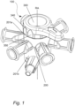
- valve devices typically used within an IV-system
- a common valve device is the stopcock valve device.
- the stopcock valve device compromises typically of two key components, a valve house and a rotatable valve member, also called a rotor.
- the rotor is arranged at least partly inside the valve house.
- the valve house and the rotor share a common rotational axis.
- the simplest stopcock has only one inlet and one outlet, and is basically just an ON or OFF switch.
- the rotor has a manipulating device shaped as a valve handle and is normally integrated with the rotor so the user can rotate the rotor to different rotational positions to control fluid of the valve.
- the handle typically has two protruding grip vanes, that represents the fluid path of the valve.
- the grip vanes When the grip vanes are aligned with the inlet and outlet there is a fluid path from the inlet to the outlet, and when the grip vanes is rotated transverse to the inlet and outlet there is no fluid path between the inlet and the outlet of the valve.
- the OFF -handle design normally has only one grip vane and it indicates, when the handle is co-aligned with an inlet, that this inlet is closed off from fluid communication.
- the handle grip vane(s) are thereby a representation of the fluid flow within the rotor.
- a single-level stopcock may usually have 90 or 180 degree spacing between inlets, a multi-level may have 60 degree.
- more interactive pairs may be used in the collar.
- Another object of the disclosure is to provide an enhanced axial locking mechanism of the rotor in an axial position inside the valve house.
- the rotor and house are axially fixed by an annular protruding ring of the rotor that fits into the annular recess of the top part of the house.
- the rotor collar When mounting the rotor axially in place inside the house, the rotor collar will first enclose and reach below the top part of the house, before the top part of the house deflects outwards due to the rotor annular ring. When the rotor is pressed in place the top part of the relatively hard house compared to the collar will force the collar to deflect outwards but not enough to plastically deform the collar.
- valve for administering drug fluid as defined in appended independent claim 1. Further aspects are defined by the appended dependent claims.
- Rotational position should be interpreted as any angular position of the rotor around the rotational axis.
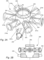
- Fig. 2A is showing the house 200 with the rotational axis RA.
- the top part 201a has interaction means made by protruding notches 204, that are angularly spaced around rotational axis at 90 degree apart.
- the inner circumferential surface 202 has a circumference smaller than the circumference of the outer circumferential surface 203.
- the rotor is axially locked in place by a retainer undercut 205 formed at the top part 201a of the house.
- the house has one or more inlets 210a-f, for received drug fluids. All inlets 210a-f, are arranged at the same plane transverse the rotational axis. As best seen in Fig.
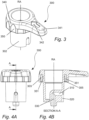
- Fig. 3, 4A and 4B that is showing the rotor 300, with the rotational axis RA.
- the rotor has an outer surface 302 that is sealingly engaging the inner circumferential surface of the house 202 shown in Fig 2 .
- the rotor is attached to a manipulating device 340 that is in this embodiment shown as integrated with the rotor.
- the annular collar 350 is axially placed below the manipulating device.
- the rotor has in this embodiment two inlets, where the inlet channel 310 is extending radially from the inner rotational axis to the outer circumferential surface 302.
- the inlet channel 310 can receive fluid from the respective one of the fluid inlets 210a-f when the rotor is positioned to the position where the radially extending inlet channel 310 is rotationally aligned with an inlet.
- the open recess inlet 320 can in this embodiment receive fluid from the inlet 220 shown in FIG 2B . in any rotational positions of the rotor.
- the centrally placed outlet of the rotor 330 is co-axial with the rotational axis and is always in fluid communication with the outlet 230 shown in FIG 2A,2B .
- the collar 350 extending in an axially direction and partly encloses the top part 201a of the house 200 so that the grooves 351 and the protruding notches 204 can engage with each other in each intended rotational position.
- the grooves 351 and the protruding notches 204 can engage with each other in each functional position.
- the collar will deflect radially outwards due to its softer material compared to the housing material and due to the collar relatively flexible and thin design.
- the annular extending protruding ring 305 is locking together with the annular recessed undercut 205 of the top part 201a of the house.
Landscapes
- Engineering & Computer Science (AREA)
- Health & Medical Sciences (AREA)
- General Engineering & Computer Science (AREA)
- Heart & Thoracic Surgery (AREA)
- Mechanical Engineering (AREA)
- Anesthesiology (AREA)
- Pulmonology (AREA)
- Biomedical Technology (AREA)
- Hematology (AREA)
- Life Sciences & Earth Sciences (AREA)
- Animal Behavior & Ethology (AREA)
- General Health & Medical Sciences (AREA)
- Public Health (AREA)
- Veterinary Medicine (AREA)
- Infusion, Injection, And Reservoir Apparatuses (AREA)
Claims (5)
- Ventil zum Verabreichen eines Arzneimittelfluids, umfassend:- eine Rotationsachse (RA),- mindestens einen Einlass (210a-f; 220) zur Aufnahme eines Arzneimittelfluids,- einen Ventilauslass (230),- einen Gehäusekörper (200),- einen Rotor (300), und- eine Manipulationsvorrichtung (340), die dazu konfiguriert ist, den Rotor so zu manipulieren, dass er um die Rotationsachse rotiert,wobei der Gehäusekörper (200) aufweist:- einen inneren Hohlraum,- eine innere Umfangsabdichtoberfläche (202),- einen oberen Teil (201a) und einen unteren Teil (201b), die entlang der Rotationsachse (RA) voneinander beabstandet sind, wobei sich der untere Teil (201b) entlang der Rotationsachse weiter distal von der Manipulationsvorrichtung befindet als der obere Teil und wobei der obere Teil eine äußere Umfangsoberfläche mit einem Umfang aufweist, der größer ist als die innere Umfangsoberfläche, und hervorstehende Rippen auf der äußeren Umfangsoberfläche,wobei der Rotor aufweist:- eine Umfangsabdichtoberfläche,- einen ringförmigen Kragen (350), der einen größeren Umfang als die äußere Umfangsoberfläche des Oberteils des Gehäuses aufweist und der den oberen Teil des Hauskörpers mindestens teilweise umschließt, wobei der ringförmige Kragen axiale Aussparungsnuten (351) aufweist, die so angeordnet sind, dass sie mit den hervorstehenden Rippen des Gehäusekörpers in Eingriff kommen,- einen ringförmigen hervorstehenden Ring (305) und- einen Durchgang (310, 330), der einen in der Umfangsabdichtoberfläche des Rotors angeordneten Einlass und einen koaxial zur Rotationsachse angeordneten und stets in Fluidverbindung mit dem Ventilauslass (230) stehenden Auslass aufweist,wobei der Rotor um die Rotationsachse rotierbar ist und mindestens teilweise innerhalb des inneren Hohlraums des Gehäusekörpers angeordnet ist, wobei die Umfangsabdichtoberfläche des Rotors in abdichtendem Eingriff mit der inneren Umfangsabdichtoberfläche des Gehäuses steht und der Rotor so konfiguriert ist, dass er in eine beliebige ausgewählte einer Vielzahl von Rotationspositionen rotiert werden kann, die durch die in Eingriff mit den hervorstehenden Rippen stehenden Aussparungsnuten definiert sind, und wobei der obere Teil des Gehäusekörpers eine ringförmige Aussparung (205) aufweist und der ringförmige Kragen axial über den hervorstehenden ringförmigen Ring (305) des Rotors hinausragt, um einen Verriegelungsmechanismus bereitzustellen, der durch eine radial nach außen gerichtete Kraft vom oberen Teil des Gehäusekörpers aktiviert wird, der eine radial nach innen gerichtete Kraft vom umschließenden Kragen entgegenwirkt.
- Ventil nach Anspruch 1, wobei der mindestens eine Einlass (210a-f; 220) eine Vielzahl von Einlässen (210a-f; 220) ist, die einen ersten Einlass einschließt, der sich in einer Ebene quer zur Rotationsachse befindet und axial von den anderen Einlässen (201a-f) der Vielzahl von Einlässen entlang der Rotationsachse beabstandet ist, und wobei in allen Rotationspositionen eine Fluidverbindung zwischen dem ersten Einlass und dem Auslass besteht.
- Ventil nach Anspruch 1 oder 2, wobei die hervorstehenden Rippen auf der äußeren Umfangsoberfläche und die axialen Aussparungen auf dem ringförmigen Kragen so angeordnet sind, dass die taktile Reaktion zwischen jeder Funktionsposition des Ventils weniger als 45 Grad beträgt.
- Ventil nach einem der vorhergehenden Ansprüche, wobei die Anzahl der axialen Aussparungsnuten (351) zwischen 4 und 12 liegt.
- Ventil nach einem der vorhergehenden Ansprüche, wobei die axialen Aussparungsnuten (351) im gleichen Winkelabstand angeordnet sind.
Applications Claiming Priority (1)
| Application Number | Priority Date | Filing Date | Title |
|---|---|---|---|
| SE2030367A SE545743C2 (en) | 2020-12-18 | 2020-12-18 | A valve device for a multilevel stopcock, the valve device comprising a manipulating device configured to create a tactile feel |
Publications (3)
| Publication Number | Publication Date |
|---|---|
| EP4015030A1 EP4015030A1 (de) | 2022-06-22 |
| EP4015030B1 true EP4015030B1 (de) | 2025-04-16 |
| EP4015030C0 EP4015030C0 (de) | 2025-04-16 |
Family
ID=74086365
Family Applications (1)
| Application Number | Title | Priority Date | Filing Date |
|---|---|---|---|
| EP21216047.7A Active EP4015030B1 (de) | 2020-12-18 | 2021-12-20 | Verbessertes tastgefühl für einen mehrstufigen absperrhahn |
Country Status (3)
| Country | Link |
|---|---|
| EP (1) | EP4015030B1 (de) |
| ES (1) | ES3035994T3 (de) |
| SE (1) | SE545743C2 (de) |
Citations (1)
| Publication number | Priority date | Publication date | Assignee | Title |
|---|---|---|---|---|
| EP3191168B1 (de) * | 2014-09-10 | 2019-01-02 | Cyto365 Ab | Ventil zur verabreichung mehrerer fluider medikamente |
Family Cites Families (4)
| Publication number | Priority date | Publication date | Assignee | Title |
|---|---|---|---|---|
| DE102011108787A1 (de) * | 2011-07-29 | 2013-01-31 | Fresenius Medical Care Deutschland Gmbh | Medizinischer Port, Blutschlauch zur Verwendung bei einer extrakorporalen Blutbehandlung sowie medizinische Behandlungsvorrichtung |
| US10357604B2 (en) * | 2016-03-08 | 2019-07-23 | Cyto365 Ab | Valve and a method for administering a plurality of drug fluids |
| WO2019070028A1 (ja) * | 2017-10-06 | 2019-04-11 | ニプロ株式会社 | 流路切り換え装置 |
| US10788135B2 (en) * | 2018-02-09 | 2020-09-29 | Nordson Corporation | Multi-port valve |
-
2020
- 2020-12-18 SE SE2030367A patent/SE545743C2/en unknown
-
2021
- 2021-12-20 ES ES21216047T patent/ES3035994T3/es active Active
- 2021-12-20 EP EP21216047.7A patent/EP4015030B1/de active Active
Patent Citations (1)
| Publication number | Priority date | Publication date | Assignee | Title |
|---|---|---|---|---|
| EP3191168B1 (de) * | 2014-09-10 | 2019-01-02 | Cyto365 Ab | Ventil zur verabreichung mehrerer fluider medikamente |
Also Published As
| Publication number | Publication date |
|---|---|
| ES3035994T3 (en) | 2025-09-11 |
| SE2030367A1 (en) | 2020-12-21 |
| EP4015030C0 (de) | 2025-04-16 |
| SE545743C2 (en) | 2023-12-27 |
| EP4015030A1 (de) | 2022-06-22 |
Similar Documents
| Publication | Publication Date | Title |
|---|---|---|
| EP1221322B1 (de) | Absperrhahnventil | |
| EP2808586B1 (de) | Absperrhahn | |
| US9212762B2 (en) | Multi-port stopcock valve and flow designating system | |
| JP6069318B2 (ja) | 医療用ポート、体外血液処理用の血液ホース並びに医療処理装置 | |
| EP3191168B1 (de) | Ventil zur verabreichung mehrerer fluider medikamente | |
| US20160287857A1 (en) | Connector with Seal Element and Adapted Connector Parts | |
| RU2676427C2 (ru) | Клапан для введения жидких лекарственных средств и способ управления таким клапаном | |
| US10960135B2 (en) | Valve and a method for administering a plurality of drug fluids | |
| IL323300A (en) | Luer-proof connector and valve assembly for adapter | |
| EP4015030B1 (de) | Verbessertes tastgefühl für einen mehrstufigen absperrhahn | |
| WO2015112803A1 (en) | Medical stopcock valve | |
| JP6935052B2 (ja) | 三方活栓 | |
| EP3919113A1 (de) | Medizinisches instrument | |
| IL287544A (en) | Sealed lower connector and valve assembly to adapter |
Legal Events
| Date | Code | Title | Description |
|---|---|---|---|
| PUAI | Public reference made under article 153(3) epc to a published international application that has entered the european phase |
Free format text: ORIGINAL CODE: 0009012 |
|
| STAA | Information on the status of an ep patent application or granted ep patent |
Free format text: STATUS: THE APPLICATION HAS BEEN PUBLISHED |
|
| AK | Designated contracting states |
Kind code of ref document: A1 Designated state(s): AL AT BE BG CH CY CZ DE DK EE ES FI FR GB GR HR HU IE IS IT LI LT LU LV MC MK MT NL NO PL PT RO RS SE SI SK SM TR |
|
| STAA | Information on the status of an ep patent application or granted ep patent |
Free format text: STATUS: REQUEST FOR EXAMINATION WAS MADE |
|
| 17P | Request for examination filed |
Effective date: 20221213 |
|
| RBV | Designated contracting states (corrected) |
Designated state(s): AL AT BE BG CH CY CZ DE DK EE ES FI FR GB GR HR HU IE IS IT LI LT LU LV MC MK MT NL NO PL PT RO RS SE SI SK SM TR |
|
| P01 | Opt-out of the competence of the unified patent court (upc) registered |
Effective date: 20230525 |
|
| GRAP | Despatch of communication of intention to grant a patent |
Free format text: ORIGINAL CODE: EPIDOSNIGR1 |
|
| STAA | Information on the status of an ep patent application or granted ep patent |
Free format text: STATUS: GRANT OF PATENT IS INTENDED |
|
| RIC1 | Information provided on ipc code assigned before grant |
Ipc: F16K 35/04 20060101ALI20241028BHEP Ipc: F16K 11/085 20060101ALI20241028BHEP Ipc: A61M 39/22 20060101AFI20241028BHEP |
|
| INTG | Intention to grant announced |
Effective date: 20241113 |
|
| GRAS | Grant fee paid |
Free format text: ORIGINAL CODE: EPIDOSNIGR3 |
|
| GRAA | (expected) grant |
Free format text: ORIGINAL CODE: 0009210 |
|
| STAA | Information on the status of an ep patent application or granted ep patent |
Free format text: STATUS: THE PATENT HAS BEEN GRANTED |
|
| AK | Designated contracting states |
Kind code of ref document: B1 Designated state(s): AL AT BE BG CH CY CZ DE DK EE ES FI FR GB GR HR HU IE IS IT LI LT LU LV MC MK MT NL NO PL PT RO RS SE SI SK SM TR |
|
| REG | Reference to a national code |
Ref country code: GB Ref legal event code: FG4D |
|
| REG | Reference to a national code |
Ref country code: CH Ref legal event code: EP |
|
| REG | Reference to a national code |
Ref country code: IE Ref legal event code: FG4D |
|
| U01 | Request for unitary effect filed |
Effective date: 20250416 |
|
| P04 | Withdrawal of opt-out of the competence of the unified patent court (upc) registered |
Free format text: CASE NUMBER: APP_19007/2025 Effective date: 20250421 |
|
| U07 | Unitary effect registered |
Designated state(s): AT BE BG DE DK EE FI FR IT LT LU LV MT NL PT RO SE SI Effective date: 20250424 |
|
| REG | Reference to a national code |
Ref country code: ES Ref legal event code: FG2A Ref document number: 3035994 Country of ref document: ES Kind code of ref document: T3 Effective date: 20250911 |
|
| PG25 | Lapsed in a contracting state [announced via postgrant information from national office to epo] |
Ref country code: NO Free format text: LAPSE BECAUSE OF FAILURE TO SUBMIT A TRANSLATION OF THE DESCRIPTION OR TO PAY THE FEE WITHIN THE PRESCRIBED TIME-LIMIT Effective date: 20250716 Ref country code: GR Free format text: LAPSE BECAUSE OF FAILURE TO SUBMIT A TRANSLATION OF THE DESCRIPTION OR TO PAY THE FEE WITHIN THE PRESCRIBED TIME-LIMIT Effective date: 20250717 |
|
| PG25 | Lapsed in a contracting state [announced via postgrant information from national office to epo] |
Ref country code: PL Free format text: LAPSE BECAUSE OF FAILURE TO SUBMIT A TRANSLATION OF THE DESCRIPTION OR TO PAY THE FEE WITHIN THE PRESCRIBED TIME-LIMIT Effective date: 20250416 |
|
| PG25 | Lapsed in a contracting state [announced via postgrant information from national office to epo] |
Ref country code: HR Free format text: LAPSE BECAUSE OF FAILURE TO SUBMIT A TRANSLATION OF THE DESCRIPTION OR TO PAY THE FEE WITHIN THE PRESCRIBED TIME-LIMIT Effective date: 20250416 |
|
| PG25 | Lapsed in a contracting state [announced via postgrant information from national office to epo] |
Ref country code: RS Free format text: LAPSE BECAUSE OF FAILURE TO SUBMIT A TRANSLATION OF THE DESCRIPTION OR TO PAY THE FEE WITHIN THE PRESCRIBED TIME-LIMIT Effective date: 20250716 |
|
| PG25 | Lapsed in a contracting state [announced via postgrant information from national office to epo] |
Ref country code: IS Free format text: LAPSE BECAUSE OF FAILURE TO SUBMIT A TRANSLATION OF THE DESCRIPTION OR TO PAY THE FEE WITHIN THE PRESCRIBED TIME-LIMIT Effective date: 20250816 |
|
| U20 | Renewal fee for the european patent with unitary effect paid |
Year of fee payment: 5 Effective date: 20251117 |
|
| PGFP | Annual fee paid to national office [announced via postgrant information from national office to epo] |
Ref country code: GB Payment date: 20251117 Year of fee payment: 5 |
|
| PG25 | Lapsed in a contracting state [announced via postgrant information from national office to epo] |
Ref country code: SM Free format text: LAPSE BECAUSE OF FAILURE TO SUBMIT A TRANSLATION OF THE DESCRIPTION OR TO PAY THE FEE WITHIN THE PRESCRIBED TIME-LIMIT Effective date: 20250416 |
|
| PG25 | Lapsed in a contracting state [announced via postgrant information from national office to epo] |
Ref country code: CZ Free format text: LAPSE BECAUSE OF FAILURE TO SUBMIT A TRANSLATION OF THE DESCRIPTION OR TO PAY THE FEE WITHIN THE PRESCRIBED TIME-LIMIT Effective date: 20250416 |
|
| PG25 | Lapsed in a contracting state [announced via postgrant information from national office to epo] |
Ref country code: SK Free format text: LAPSE BECAUSE OF FAILURE TO SUBMIT A TRANSLATION OF THE DESCRIPTION OR TO PAY THE FEE WITHIN THE PRESCRIBED TIME-LIMIT Effective date: 20250416 |