EP4014803A1 - Getränkebereiter mit sensorvorrichtung - Google Patents
Getränkebereiter mit sensorvorrichtung Download PDFInfo
- Publication number
- EP4014803A1 EP4014803A1 EP21210504.3A EP21210504A EP4014803A1 EP 4014803 A1 EP4014803 A1 EP 4014803A1 EP 21210504 A EP21210504 A EP 21210504A EP 4014803 A1 EP4014803 A1 EP 4014803A1
- Authority
- EP
- European Patent Office
- Prior art keywords
- beverage maker
- beverage
- sensor
- maker according
- control device
- Prior art date
- Legal status (The legal status is an assumption and is not a legal conclusion. Google has not performed a legal analysis and makes no representation as to the accuracy of the status listed.)
- Granted
Links
Images


Classifications
-
- A—HUMAN NECESSITIES
- A47—FURNITURE; DOMESTIC ARTICLES OR APPLIANCES; COFFEE MILLS; SPICE MILLS; SUCTION CLEANERS IN GENERAL
- A47J—KITCHEN EQUIPMENT; COFFEE MILLS; SPICE MILLS; APPARATUS FOR MAKING BEVERAGES
- A47J31/00—Apparatus for making beverages
- A47J31/44—Parts or details or accessories of beverage-making apparatus
- A47J31/4485—Nozzles dispensing heated and foamed milk, i.e. milk is sucked from a milk container, heated and foamed inside the device, and subsequently dispensed from the nozzle
Definitions
- the invention is therefore based on the object of providing a beverage maker with reliably good beverage quality.
- milk drinks are prepared better and more reliably of good quality overall.
- it is prevented that spoiled milk or milk in the beginning of acidification is used for the preparation.
- the line system that carries the milk becomes clogged due to stagnant milk, as a result of which complex cleaning processes are avoided overall.
- the supply device of the beverage maker includes a sensor device with a sensor means and an evaluation means, the sensor device being set up to detect the total acidity of the liquid in which the sensor means is immersed.
- the control device is here in terms of data technology or signal technology with the Sensor device in connection to take action based on the detected degree of acidity that prevent preparation of a spoiled drink.
- the SH value which is a reliable measure of the condition of the milk and its suitability for processing in the beverage maker, is preferably used as the total acidity.
- the sensor means of the sensor device includes electrodes for measuring an electrical property, preferably designed as a photochemical or biochemical sensor, which is located in the container docked to the line system.
- the evaluation means is designed to determine or ascertain the SH value on the basis of the measured electrical property and to supply it to the control device.
- the evaluation means includes a table, mathematical model or a conversion formula for determining the SH value based on the value of the sensor, ie the electrical property such as conductance, impedance or capacitance detected by the sensor.
- the evaluation means can be in the form of a computer unit with a microcontroller, with the table, the mathematical model or the conversion formula being implemented as program code, preferably changeable program code.
- the mentioned function can also be implemented in the control device, so that the microcontroller of the control device takes over these tasks and no additional microcontroller has to be used.
- the sensor device is set up to measure the electrical properties cyclically in order to record a time profile of the electrical properties.
- the change in the freshness or acidification status of the milk in the storage container can thus be observed over a longer storage period.
- the degree of acidity in particular the SH value, shows strong deviations that depend on the nature of the milk that is already fresh. For this reason, it makes sense to observe the freshly poured milk for several hours or days.
- Fresh milk usually has an SH value in the range of 6.5 to 7.5.
- Milk in the early stages of acidification usually has an SH value in the range from 7.6 to 9.6.
- Milk in the state of thick flaky coagulation generally has an SH value greater than 9.6.
- An increase of approx. 2 can therefore be regarded as the limit value for the change for the onset of acidification compared to the recorded value for the freshness state.
- An increase of 2 can therefore be regarded as the limit value for the change for acidification with flocculent coagulation compared to the recorded value for the freshness state.
- the evaluation means is set up to determine the dynamics, ie the size of the change in the electrical quantity within a predetermined time segment, and to determine the SH value from this using the table, the mathematical model or the conversion formula.
- Small changes usually do not lead to a significant reduction in quality.
- this is usually an indication of an intensive or strong change in the SH value.
- These dynamics can be supplied by the mathematical model, table or formula and evaluated accordingly.
- the change in the electrical properties of the liquid ingredient in the storage container is determined as a function of the storage time.
- the sensor means comprises two electrodes spaced apart from one another, which are attached to the inlet of the intake manifold.
- the sensor means is thus located directly at the free end of the intake pipe, which dips into the milk.
- the electrodes consist of at least two plates, which are arranged parallel and spaced apart from one another.
- this is designed as a tubular hollow body with a segmented jacket, with the individual segments functioning as electrodes.
- This can be integrated as a piece of pipe placed on the free end of the intake pipe and does not affect the flow. Furthermore, the accessibility of the interior of the intake pipe is not impaired, so that cleaning is easy.
- control device is set up or the microcontroller in the control device is programmed to control the fluid system as a function of the recorded or determined degree of acidity, preferably the SH value.
- the control device can then issue a warning message to the user if the stored milk is no longer suitable for preparing a drink.
- control device can be set up to prevent the beverage preparation for milk-containing beverages or to interrupt a preparation that has already started, in which case in particular the dispensing of milk is prevented.
- the beverage maker also includes an operating and display device that is connected to the control device and is designed to provide user inputs and information output.
- the control device is set up to output information on the display device if the degree of acidity or SH value determined by the sensor device exceeds a limit value.
- the absolutely determined degree of acidity or SH value or the Measure of the change can be used, as explained above.
- Information about the freshness status, a status for the beginning of acidification and for acidification with flake formation can preferably be provided as information outputs.
- An interruption or refusal of beverage preparation is not necessary for the first two states. The drink cannot be prepared for the latter condition because, on the one hand, the quality cannot be achieved and because the milk-carrying lines can become clogged due to the formation of flakes.
- the beverage maker is designed as a built-in device for installation in a cupboard with a niche on or in the body that is accessible from the outside and has at least one boundary wall, with the outlet device being designed to be movable within the niche relative to the body and to the beverage container storage section and the intake pipe with the sensor means is arranged or can be coupled in the niche.
- the accommodation of the sensor device is particularly advantageous here, because the milk storage container with the suction pipe integrated therein can be docked with sensor means by means of a coupling device arranged in the niche.
- the hot beverage machine 100 is designed as a fully automatic coffee machine, in the example shown as a built-in fully automatic coffee machine.
- the hot beverage machine 100 has a body 110, the components for preparing the hot beverage are housed within the body. These are, schematically sketched, the reservoir 141 for water and for coffee beans 142, a grinder 145, the brewing unit 146 and the flow line system 147 with pump 148, flow heater 149 and sensors for measuring water temperature and/or flow rate.
- the hot beverage machine 100 also has an operating and display device 190 for entering the user's wishes, which is connected to a control device 180 for controlling the components for preparing the desired hot beverage and a beverage container storage section or a storage surface 115 .
- the beverage container storage section 115 is provided as a recess 160 molded or otherwise produced in the front door 150 for closing the interior of the body 110 .
- the Beverage container storage section 115 is designed for storing beverage containers 130, such as coffee cups.
- the hot beverage machine 100 has an outlet device 120 with outlet nozzles 125 .
- the outlet device 120 is designed to be movable relative to the body 110 or relative to the beverage container storage section 115 .
- the outlet device 120 is in an in figure 1 illustrated operating position of the hot beverage machine 100 above the beverage container storage section 115 is arranged.
- the outlet device 120 can be moved towards the beverage container storage section 115 and away from the beverage container storage section 115, for example actuated manually or by a drive device in the body 110.
- the outlet device 120 is designed overall to fill at least one beverage container 130.
- the storage section 115 is located in the niche 160 which is delimited by two opposite side walls 162 and the rear wall 161 facing the body 110 .
- the niche 160 is located in the door 150, so that the delimiting walls 161, 162 and the shelf 115 are also moved when the door 150 is swung open.
- FIG. 2 shows a schematic block diagram of the flow line system 140 with the controller 180, 190 of a drinks machine 100 according to an embodiment.
- the arrangement shown here can be used in the figure 1 be used vending machine 100 described.
- the drinks machine 100 has a liquid reservoir 141 which is designed to store liquid 202, for example water.
- the liquid is used both for preparing a drink and for generating steam for sucking in and foaming the other liquid, preferably milk, stored in the liquid reservoir 170 .
- the liquid reservoir 141 is connected via a line to a pumping device 148, which is also referred to as a pump.
- the pumping device 148 is designed to pump the liquid to a heating device 149 in which the liquid is heated and steam is optionally generated.
- the liquid heated by the heating device 149 can be conducted in liquid or vapor form to a brewing unit 147 of the drinks machine 100 in order to prepare a coffee drink, for example, which is then dispensed through the outlet nozzle 125 .
- the steam generated by the heating device 149 can be routed to a mixing chamber 172 or frothing device of the drinks machine 100 .
- the frothing device 172 is designed to suck in and froth the other liquid, for example milk, from the liquid reservoir 170 using the steam and to the outlet nozzle 126 respectively.
- the further liquid is fed from the liquid reservoir 170 into the mixing chamber 172 via the feed line 171 .
- the mixing chamber 172 is heated by the steam entering the mixing chamber 172.
- a valve assembly 143 is disposed in the line downstream of the heater 149 to selectively direct the heated water flow paths to the brewing unit 147 or to the mixing chamber 172 .
- the valve device 143 is also designed in such a way that it can open or block the passage to the mixing chamber 172 .
- the intake pipe 171 is preferably detachably connected to the mixing chamber 172 by means of a coupling device 173 .
- the intake pipe 171 is provided with a sensor means 210 which is assigned to the sensor device 200 for detecting the milk quality.
- the sensor means 210 includes additional components for directly measuring electrical properties such as conductance, impedance or capacitance, with the evaluation device 280 determining or calculating the degree of acidity of the liquid from the measured values.
- the control device 180 includes a microcontroller uC with a correspondingly assigned memory MEM as a program and data memory.
- the control device 180 is in a data connection with the operating and display device 190 in order to receive user inputs based on operating actions and to output information and warnings to the user.
- the operating and display device 190 preferably includes a display in order to output information to the user in a comprehensible manner in text form or graphically.
- the display can preferably be in the form of a touch screen 190, which provides particularly convenient and versatile operation.
- the sensor means 210 comprises a carrier 212 or a carrier frame on which two plates 214, 216 are attached in parallel spaced apart relationship.
- the plates 214,216 serve as electrodes to measure electrical properties of the liquid M located in the space 230 between the two plates 214,216.
- the plates 214, 216 are attached to the free end or the inlet side 171a of the intake pipe 171, the plates 214, 216 being arranged parallel to the cross-section of the pipe opening 171a.
- the distance or space 230 between the two plates 214, 216 provides the inlet port 171a for the intake manifold 171 ready.
- the sensor means 210 includes a carrier 212 which is designed as a cylindrical hollow body.
- the two plates 214, 216 are formed as shell segments and are attached opposite one another in the cylinder shell 212.
- the surfaces of the casing segments 214, 216 are spaced apart to each other.
- the shell segment shaped plates 214, 216 serve as electrodes to measure electrical properties of the liquid M, which is in the space between the two plates 214, 216.
- the plates 214, 216 with the cylindrical support 212 are attached to the free end or to the inlet side 171a of the intake pipe 171.
- the distance or space 230 between the two plates 214, 216 provides the inlet port 171a for the intake manifold 171 ready.
- the plates 214, 216 are connected to the evaluation means 280 in terms of signals.
- the evaluation means 280 can stimulate the electrodes 214, 216 and/or receive electrical properties and convert them to a digital value, which in turn can be supplied to the control device 180 for further processing.
- the evaluation means 280 can also be implemented as part of the control device or the control device 180 can be designed to take over some or all of the tasks of the evaluation means 280 . This applies to all embodiments of the invention.
- the direction and position information for all versions relates to the operational position of the beverage machine 100.
Landscapes
- Engineering & Computer Science (AREA)
- Food Science & Technology (AREA)
- Apparatus For Making Beverages (AREA)
Abstract
- einen Korpus (110);
- ein Fluidsystem im Korpus angeordnetes Fluidsystem (147);
- eine Steuereinrichtung (180) zur Steuerung des Fluidsystems (147) zur Zubereitung eines Getränks;
- eine Auslassvorrichtung (120, 125, 126) zur Ausgabe des zubereiteten Getränks;
- eine Zuführvorrichtung (171, 172) zum Zuführen einer weiteren flüssigen Zutat, beispielsweise Milch (M), umfassend ein Ansaugrohr (171) zum Eintauchen in einen Vorratsbehälter (170) für die flüssige Zutat (M).
Description
- Die Erfindung betrifft einen Getränkebereiter, umfassend
- einen Korpus;
- ein Fluidsystem im Korpus angeordnetes Fluidsystem;
- eine Steuereinrichtung zur Steuerung des Fluidsystems zur Zubereitung eines Getränks;
- eine Auslassvorrichtung zur Ausgabe des zubereiteten Getränks;
- eine Zuführvorrichtung zum Zuführen einer weiteren flüssigen Zutat, beispielsweise Milch, umfassend ein Ansaugrohr zum Eintauchen in einen Vorratsbehälter für die flüssige Zutat.
- Aus der
EP 2 594 172 B1 ist ein Getränkebereiter mit einem entsprechendem Fluidsystem bekannt und einer Zuführvorrichtung zum Ansaugen von Milch aus einem am Gehäuse angedocktem Milchbehälter. Nachteilig hierbei ist, dass dem Anwender keine Information über den Zustand der Milch angegeben wird. Der Anwender muss also selber darauf achten, dass die im Vorratsbehälter befindliche Milch frisch genug für die Getränkezubereitung ist. Sobald der Anwender dies vergisst, kann es vorkommen, dass verdorbene oder im Ansatz übersäuerte Milch zum Getränk verarbeitet wird, das dann insgesamt nicht verzehrt werden kann. - Der Erfindung liegt somit die Aufgabe zugrunde, einen Getränkebereiter mit einer zuverlässig guten Getränkequalität bereitzustellen.
- Erfindungsgemäß wird unter anderem diese Aufgabe durch einen Getränkebereiter mit den Merkmalen des unabhängigen Anspruchs 1 gelöst. Vorteilhafte Ausgestaltungen und Weiterbildungen der Erfindung ergeben sich aus den nachfolgenden abhängigen Ansprüchen.
- Die mit der Erfindung erreichbaren Vorteile bestehen darin, dass Milchgetränke insgesamt besser und zuverlässig von guter Qualität zubereitet werden. Insbesondere wird verhindert, dass verdorbene oder im Beginn der Säuerung befindliche Milch für die Zubereitung verwendet wird. Ferner wird vermieden, dass das Leitungssystem, das Milch führt, aufgrund stockender Milch verstopft, wodurch insgesamt aufwändige Reinigungsprozesse vermeiden werden.
- Hierzu umfasst die Zuführvorrichtung des Getränkebereiters eine Sensorvorrichtung mit einem Sensormittel und ein Auswertemittel, wobei die Sensorvorrichtung dazu eingerichtet ist, die Gesamtacidität der Flüssigkeit zu erfassen, in die das Sensormittel eingetaucht ist. Die die Steuereinrichtung steht hierbei datentechnisch oder signaltechnisch mit der Sensorvorrichtung in Verbindung, um aufgrund des erfassten Säuregrades Maßnahmen zu ergreifen, die eine Zubereitung eines verdorbenen Getränks verhindern.
- Bevorzugt wird als Gesamtacidität der SH-Wert herangezogen, der ein zuverlässiges Maß für den Zustand der Milch bzw. die Eignung zur Verarbeitung in dem Getränkebereiter darstellt.
- In einer zweckmäßigen Ausführung umfasst das Sensormittel der Sensorvorrichtung Elektroden zur Messung einer elektrischen Eigenschaft, bevorzugt als photochemischer oder biochemischer Sensor ausgebildet, die sich in dem am Leitungssystem angedockten Behälter befindet. Das Auswertemittel ist dazu ausgebildet, den SH-Wert aufgrund der gemessenen elektrischen Eigenschaft zu bestimmen oder ermitteln und der Steuereinrichtung zuzuführen.
- In einer bevorzugten Weiterbildung umfasst das Auswertemittel eine Tabelle, Mathematisches Modell oder eine Umrechnungsformel zur Bestimmung des SH Wertes basierend auf den Wertes des Sensors, also der vom Sensor erfassten elektrischen Eigenschaft wie Leitwert, Impedanz oder Kapazität. Das Auswertemittel kann als Rechnereinheit mit einem Mikrocontroller ausgebildet sein, wobei die Tabelle, das mathematische Modell oder die Umrechnungsformel als Programmcode, bevorzugt veränderbarer Programmcode, implementiert ist. Die genannte Funktion kann auch in der Steuereinrichtung implementiert sein, sodass der Mikrocontroller der Steuereinrichtung diese Aufgaben mit übernimmt und kein zusätzlicher Mikrocontroller eingesetzt werden muss.
- In einer insgesamt vorteilhaften Ausführung ist die Sensorvorrichtung dazu eingerichtet, die elektrischen Eigenschaften zyklisch in zu messen, um einen zeitlichen Verlauf der elektrischen Eigenschaften aufzunehmen. Damit kann die Veränderung des Frischezustandes bzw. Säuerungszustandes der im Vorratsbehälter befindlichen Milch über eine längere Lagerzeit beobachtet werden. Das Maß für den Säuregrad, insbesondere der SH-Wert weist starke Abweichungen aus, die von der Beschaffenheit der bereits frischen Milch abhängen. Aus diesem Grund ist es sinnvoll, die frisch eingefüllte Milch für mehrere Stunden oder Tage zu beobachten. Sobald die Veränderung einen Grenzwert überschritten hat, kann von einer beginnenden Säuerung bzw. fortgeschrittenen Säuerung mit gerinnungsbedingten Ausflockungen ausgegangen werden. Frische Milch weist in der Regel einen SH-Wert im Bereich von 6,5 bis 7,5 auf. Milch im Zustand beginnender Säuerung weist in der Regel einen SH-Wert im Bereich von 7,6 bis 9,6 auf. Milch im Zustand mit dickflockiger Gerinnung weist in der Regel einen SH-Wert größer 9,6 auf. Als Grenzwert für die Veränderung kann für beginnende Säuerung deshalb eine Steigerung um ca. 2 angesehen werden, gegenüber dem erfassten Wert für den Frischezustand. Als Grenzwert für die Veränderung kann für Säuerung mit flockiger Gerinnung deshalb eine Steigerung um 2 angesehen werden, gegenüber dem erfassten Wert für den Frischezustand.
- In einer zweckmäßigen Weiterbildung ist das Auswertemittel dazu eingerichtet, die Dynamik, also Größe der Veränderung der elektrischen Größe innerhalb eines vorbestimmten Zeitabschnitts zu bestimmen, und daraus anhand der Tabelle, des Mathematischen Modells oder der Umrechnungsformel den SH Wert zu bestimmen. Kleine Veränderungen führen in der Regel nicht zu einer signifikanten Qualitätsminderung. Sobald die Veränderung der erfassten Größe stärker geschieht, ist dies in der Regel ein Indiz für eine intensive oder starke Veränderung des SH-Wertes. Diese Dynamik kann den von dem mathematischen Modell, der Tabelle oder der Formel zugeführt und entsprechend ausgewertet werden. Insgesamt wird Veränderung der elektrischen Eigenschaft der im Vorratsbehälter befindlichen flüssigen Zutat ermittelt, in Abhängigkeit von der Lagerzeit.
- In einer insgesamt zweckmäßigen Ausführung umfasst das Sensormittel zwei zueinander beabstandete Elektroden, die am Einlass des Ansaugrohres angebracht sind. Das Sensormittel befindet sich somit direkt am freien Ende des Ansaugrohres, das in die Milch eintaucht.
- In einer zweckmäßigen Weiterbildung bestehen die Elektroden aus zumindest zwei Platten, die parallel beabstandet zueinander angeordnet sind.
- In einer bevorzugten Weiterbildung des Sensormittels ist dieses als rohrförmiger Hohlkörper mit segmentierten Mantel ausgebildet ist, wobei die einzelnen Segmente als Elektroden fungieren. Damit kann das als Rohrstück auf das freie Ende das Ansaugrohres aufgesetzt integriert werden und beeinflusst nicht die Strömung. Ferner ist die Zugänglichkeit des Inneren des Ansaugrohres nicht beeinträchtigt, sodass eine einfache Reinigung gegeben ist.
- In einer insgesamt zweckmäßigen Ausführung ist die Steuereinrichtung dazu eingerichtet bzw. der Mikrocontroller in der Steuereinrichtung dazu programmiert, das Fluidsystem in Abhängigkeit des erfassten oder bestimmten Säuregrades, bevorzugt SH-Wertes, zu steuern. Die Steuereinrichtung kann dann eine Warnmeldung an den Anwender ausgeben, wenn die bevorratetet Milch nicht mehr geeignet ist zur Getränkezubereitung. Ferner kann die Steuereinrichtung dazu eingerichtet sein, die Getränkezubereitung für milchhaltige Getränke zu unterbinden bzw. eine bereits begonnene Zubereitung zu unterbrechen, wobei insbesondere der Milchbezug verhindert wird.
- In einer insgesamt zweckmäßigen Ausführung umfasst der Getränkebereiter ferner eine Bedien- und Anzeigevorrichtung, die mit der Steuereinrichtung in Verbindung steht und zur Bereitstellung von Benutzereingaben und Informationsausgaben ausgebildet ist.
- Die Steuereinrichtung ist dazu eingerichtet, eine Information auf der Anzeigevorrichtung auszugeben, wenn der von der Sensorvorrichtung bestimmte Säuregrad bzw. SH-Wert einen Grenzwert überschreitet. Hier kann der absolut ermittelte Säuregrad bzw. SH-Wert oder das Maß für die Änderung herangezogen werden, wie oben erläutert. Als Informationsausgaben können dabei bevorzugt Angaben für den Frischezustand, einen Zustand für beginnenden Säuerung und für Säuerung mit Flockenbildung bereitgestellt werden. Für die ersten beiden Zustände kann ist eine Unterbrechung oder Verweigerung der Getränkezubereitung nicht notwendig. Für den letztgenannten Zustand kann das Getränk nicht zubereitet werden, weil zum einen die Qualität nicht erreicht werden kann und weil die milchführenden Leitungen aufgrund der Flockenbildung verstopfen können.
- In einer insgesamt vorteilhaften Ausführung ist der Getränkebereiter als Einbaugerät zum Einbau in einem Schrank ausgebildet mit einer am oder im Korpus eingefügten, von außen zugängliche Nische mit zumindest einer Begrenzungswand, wobei die Auslaufvorrichtung innerhalb der Nische relativ zu dem Korpus und zu dem Getränkebehälterabstellabschnitt bewegbar ausgeführt ist und das Ansaugrohr mit dem Sensormittel in der Nische angeordnet ist oder angekoppelt werden kann. Die Unterbringung der Sensorvorrichtung ist hierbei besonders vorteilhaft, weil der Milchvorratsbehälter mit darin integriertem Ansaugrohr mit Sensormittel mittels einer in der Nische angeordneten Kuppelvorrichtung angedockt werden kann.
- Ein Ausführungsbeispiel der Erfindung ist in den Zeichnungen rein schematisch dargestellt und wird nachfolgend näher beschrieben. Es zeigen
- Fig. 1:
- einen Getränkebereiter in einer teilweise schematischen Frontansicht;
- Fig. 2:
- das Strömungsleitungssystem in schematischer Ansicht und
- Fig. 3, 4:
- die Sensorvorrichtung skizziert für verschiedene Ausführungen.
-
Fig. 1 zeigt eine perspektivische Darstellung einer Heißgetränkemaschine 100 gemäß einem Ausführungsbeispiel. Dabei ist die Heißgetränkemaschine 100 als ein Kaffeevollautomat, in dem dargestellten Beispiel als ein Einbau-Kaffeevollautomat ausgeführt. Die Heißgetränkemaschine 100 weist einen Korpus 110 auf, innerhalb des Korpus sind die Komponenten zum Zubereiten des Heißgetränks untergebracht. Diese sind, schematisch skizziert, die Vorratsbehälter 141 für Wasser und für Kaffeebohnen 142, ein Mahlwerk 145, die Brüheinheit 146 und das Strömungsleitungssystem147 mit Pumpe 148, Durchlauferhitzer 149 und Sensoren zur Messung von Wassertemperatur und/oder Durchflussmenge. Die Heißgetränkemaschine 100 besitzt ferner eine Bedien- und Anzeigevorrichtung 190 zur Eingabe der Benutzerwünsche, die mit einer Steuereinrichtung 180 in Verbindung steht zum Steuern der Komponenten zum Zubereiten des gewünschten Heißgetränks und einen Getränkebehälterabstellabschnitt oder eine Abstellfläche 115 auf. Dabei ist der Getränkebehälterabstellabschnitt 115 als eingeformte oder anders hergestellte Nische 160 in der frontseitigen Tür 150 zum Verschließen des Inneren des Korpus 110 bereitgestellt. Der Getränkebehälterabstellabschnitt 115 ist zum Abstellen von Getränkebehältern 130, beispielsweise Kaffeetassen, ausgebildet. - Ferner weist die Heißgetränkemaschine 100 eine Auslaufvorrichtung 120 mit Auslaufdüsen 125 auf. Die Auslaufvorrichtung 120 ist in einer bevorzugten Ausführung relativ zu dem Korpus 110 bzw. relativ zu dem Getränkebehälterabstellabschnitt 115 bewegbar ausgeführt. Dabei ist die Auslaufvorrichtung 120 in einer in
Figur 1 dargestellten Betriebsposition der Heißgetränkemaschine 100 oberhalb des Getränkebehälterabstellabschnittes 115 angeordnet. Die Auslaufvorrichtung 120 ist zu dem Getränkebehälterabstellabschnitt 115 hin und von dem Getränkebehälterabstellabschnitt 115 weg verfahrbar, beispielsweise manuell betätigt oder durch eine Antriebseinrichtung in dem Korpus 110. Die Auslaufvorrichtung 120 ist insgesamt dazu ausgebildet, zumindest einen Getränkebehälter 130 zu Befüllen. - Der Abstellabschnitt 115 befindet sich in der Nische 160, die durch zwei gegenüberliegende Seitenwände 162 und der dem Korpus 110 zugewandten Rückwand 161 begrenzt ist. Die Nische 160 befindet sich in der Tür 150, sodass die begrenzenden Wände 161, 162 und die Abstellfläche 115 mit bewegt werden, wenn die Tür 150 aufgeschwenkt wird.
-
Fig. 2 zeigt ein schematisches Blockschaltbild des Strömungsleitungssystems 140 mit der Steuerung 180, 190 eines Getränkeautomaten 100 gemäß einem Ausführungsbeispiel. Die hier dargestellte Anordnung kann in dem inFigur 1 beschriebenen Getränkeautomat 100 eingesetzt sein. - Der Getränkeautomat 100 weist einen Flüssigkeitsspeicher 141 auf, der ausgebildet ist, um Flüssigkeit 202, beispielsweise Wasser, zu speichern. Die Flüssigkeit wird sowohl für eine Getränkebereitung als auch für das Erzeugen von Dampf zum Ansaugen und Aufschäumen der in dem Flüssigkeitsvorrat 170 bevorrateten weiteren Flüssigkeit, bevorzugt Milch, verwendet.
- Dazu ist der Flüssigkeitsspeicher 141 über eine Leitung mit einer Pumpeinrichtung 148 verbunden, die auch als Pumpe bezeichnet wird. Die Pumpeinrichtung 148 ist ausgebildet, um die Flüssigkeit zu einer Heizeinrichtung 149 zu pumpen, in der die Flüssigkeit erhitzt wird und gegebenenfalls Dampf erzeugt wird. Die von der Heizeinrichtung 149 erhitzte Flüssigkeit kann zum einen in flüssiger oder dampfförmiger Form zu einer Brüheinheit 147 des Getränkeautomaten 100 geführt werden, um beispielsweise ein Kaffeegetränk zuzubereiten, das anschließend durch die Auslassdüse 125 ausgegeben wird. Zusätzlich kann der von der Heizeinrichtung 149 erzeugte Dampf zu einer Mischkammer 172 bzw. Aufschäumeinrichtung des Getränkeautomaten 100 geführt werden. Die Aufschäumeinrichtung 172 ist dabei ausgebildet, um die weitere Flüssigkeit, beispielsweise Milch, aus dem Flüssigkeitsvorrat 170 unter Verwendung des Dampfes anzusaugen und aufzuschäumen und zur Auslassdüse 126 zu führen. Dazu wird die weitere Flüssigkeit aus dem Flüssigkeitsvorrat 170 über die Zuführleitung 171 in die Mischkammer 172 zugeführt. Durch den in die Mischkammer 172 gelangenden Dampf erhitzt sich die Mischkammer 172.
- In einer bevorzugten Ausführung ist in der Leitung, die der Heizeinrichtung 149 nachgeschaltet ist, eine Ventilvorrichtung 143 angeordnet, um wahlweise die Strömungswege des erhitzten Wassers zur Brüheinheit 147 oder zur Mischkammer 172 zu leiten. Die Ventilvorrichtung 143 ist ferner derart ausgeführt, dass sie den Durchlass zur Mischkammer 172 freigeben oder sperren kann. Das Ansaugrohr 171 ist mittels einer Koppelvorrichtung 173 an der Mischkammer 172 bevorzugt lösbar angeschlossen.
- Zu erkennen ist ferner, dass das Ansaugrohr 171 mit einem Sensormittel 210 versehen ist, das der Sensorvorrichtung 200 zur Erkennung der Milchqualität zugeordnet ist. Das Sensormittel 210 umfasst weitere Komponenten, um elektrische Eigenschaften, wie Leitwert, Impedanz oder Kapazität, direkt zu messen, wobei die Auswerteeinrichtung 280 aus den gemessenen Werten den Säuregrad der Flüssigkeit ermittelt oder berechnet.
- Die Steuereinrichtung 180 umfasst einen Mikrocontroller uC mit einem entsprechend zugeordneten Speicher MEM als Programm- und Datenspeicher. Die Steuereinrichtung 180 steht mit der Bedien- und Anzeigevorrichtung 190 in Datenverbindung, um Benutzereingaben aufgrund Bedienhandlungen zu empfangen und Informationen und Warnhinweise an den Benutzer auszugeben. Die Bedien- und Anzeigevorrichtung 190 umfasst bevorzugt ein Display, um Informationen verständlich in Textform oder grafisch an den Benutzer auszugeben. Das Display kann bevorzugt als Berührbildschirm 190 ausgebildet sein, die eine besonders komfortable und vielseitige Bedienung bereitstellt.
-
Fig. 3 zeigt die Sensorvorrichtung 200 in einer ersten Ausführung. Das Sensormittel 210 umfasst einen Träger 212 oder ein Trägerrahmen, an dem zwei Platten 214, 216 parallel beabstandet zueinander angebracht sind. Die Platten 214, 216 dienen als Elektroden, um elektrische Eigenschaften der Flüssigkeit M zu messen, die sich im Raum 230 zwischen den beiden Platten 214, 216 befindet. Die Platten 214, 216 sind am freien Ende bzw. an der Einlassseite 171a des Ansaugrohres 171 angebracht, wobei die Platten 214, 216 parallel zum Querschnitt der Rohröffnung 171a angeordnet sind. Der Abstand bzw. der Raum 230 zwischen den beiden Platten 214, 216 stellt die Einlassöffnung 171a für das Ansaugrohr 171 bereit. -
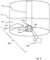
Fig. 4 zeigt die Sensorvorrichtung 200 in einer zweiten Ausführung. Das Sensormittel 210 umfasst einen Träger 212, der als zylindrischer Hohlkörper ausgebildet ist. Die beiden Platten 214, 216 sind dabei als Mantelsegmente geformt und gegenüberliegend im Zylindermantel 212 angebracht. Die Flächen der Mantelsegmente 214, 216 sind hierbei beabstandet zueinander. Die mantelsegmentförmigen Platten 214, 216 dienen als Elektroden, um elektrische Eigenschaften der Flüssigkeit M zu messen, die sich im Raum zwischen den beiden Platten 214, 216 befindet. Die Platten 214, 216 mit dem zylinderförmigen Träger 212 sind am freien Ende bzw. an der Einlassseite 171a des Ansaugrohres 171 angebracht. Der Abstand bzw. der Raum 230 zwischen den beiden Platten 214, 216 stellt die Einlassöffnung 171a für das Ansaugrohr 171 bereit. - In beiden Ausführungen sind die Platten 214, 216 signaltechnisch mit dem Auswertemittel 280 verbunden. Das Auswertemittel 280 kann die Elektroden 214, 216 anregen und/oder elektrische Eigenschaften empfangen und zu einem digitalen Wert wandeln, der wiederrum der Steuereinrichtung 180 zugeführt werden kann zur weiteren Bearbeitung. Das Auswertemittel 280 kann auch als Teil der Steuereinrichtung implementiert sein bzw. die Steuereinrichtung 180 kann dazu ausgebildet sein, ein Teil der Aufgaben oder alle Aufgaben des Auswertemittels 280 zu übernehmen. Dies gilt für alle Ausführungen der Erfindung.
- Die Richtungs- und Positionsangaben für alle Ausführungen beziehen sich auf die betriebsgemäße Position der Getränkemaschine 100.
Claims (12)
- Getränkebereiter (100), umfassend- einen Korpus (110);- ein Fluidsystem im Korpus angeordnetes Fluidsystem (147);- eine Steuereinrichtung (180) zur Steuerung des Fluidsystems (147) zur Zubereitung eines Getränks;- eine Auslassvorrichtung (120, 125, 126) zur Ausgabe des zubereiteten Getränks;- eine Zuführvorrichtung (171, 172) zum Zuführen einer weiteren flüssigen Zutat, beispielsweise Milch (M), umfassend ein Ansaugrohr (171) zum Eintauchen in einen Vorratsbehälter (170) für die flüssige Zutat (M);dadurch gekennzeichnet,
dass die Zuführvorrichtung (171, 172) eine Sensorvorrichtung (200) mit einem Sensormittel (210) und ein Auswertemittel (280) umfasst, wobei die Sensorvorrichtung (200) dazu eingerichtet ist, die Gesamtacidität der flüssigen Zutat (M) zu erfassen, wobei die Steuereinrichtung (180) mit der Sensorvorrichtung (200) in Verbindung steht. - Getränkebereiter nach Anspruch 1,
dadurch gekennzeichnet,
dass das Sensormittel (210) Elektroden (214, 216) zur Messung einer elektrischen Eigenschaft, bevorzugt als photochemischer oder biochemischer Sensor ausgebildet, wobei das Auswertemittel (280) dazu ausgebildet ist, den Säuregrad, bevorzugt den SH-Wert, anhand der gemessenen Eigenschaft zu bestimmen oder ermitteln und der Steuereinrichtung (180) zuzuführen. - Getränkebereiter nach Anspruch 2,
dadurch gekennzeichnet,
dass das Auswertemittel (208) eine Tabelle, Mathematisches Modell oder eine Umrechnungsformel umfasst zur Bestimmung des SH Wertes basierend auf den Wertes des Sensormittels (210). - Getränkebereiter nach Anspruch 2 oder 3,
dadurch gekennzeichnet
dass die Sensorvorrichtung (200) dazu eingerichtet ist, die elektrischen Eigenschaften zyklisch in zu messen, um einen zeitlichen Verlauf der elektrischen Eigenschaften aufzunehmen. - Getränkebereiter nach Anspruch 4,
dadurch gekennzeichnet
dass das Auswertemittel (280) dazu eingerichtet ist, die Dynamik, also Größe der Veränderung der elektrischen Größe innerhalb eines vorbestimmten Zeitabschnitts zu bestimmen, und daraus anhand der Tabelle, des Mathematischen Modells oder der Umrechnungsformel die Gesamtacidität bzw. SH Wert zu bestimmen. - Getränkebereiter nach einem der Ansprüche 1 bis 5,
dadurch gekennzeichnet,
dass das Sensormittel (210) zwei zueinander beabstandete Elektroden (214, 216) umfasst, die am Einlass (171a) des Ansaugrohres (170) angebracht sind. - Getränkebereiter nach Anspruch 6,
dadurch gekennzeichnet,
dass die Elektroden (214, 216) aus Platten bestehen, die parallel beabstandet zueinander angeordnet sind. - Getränkebereiter nach Anspruch 6,
dadurch gekennzeichnet,
dass das Sensormittel (210) als rohrförmiger Hohlkörper (212) mit segmentierten Mantel ausgebildet ist, wobei die einzelnen Segmente (214, 216) als Elektroden fungieren. - Getränkebereiter nach einem der Ansprüche 1 bis 8,
dadurch gekennzeichnet,
dass die Steuereinrichtung (180) dazu eingerichtet ist, das Fluidsystem (147) in Abhängigkeit des erfassten oder bestimmten Säuregrades, bevorzugt SH-Wertes, zu steuern. - Getränkebereiter nach einem der Ansprüche 1 bis 9,ferner umfassend eine Bedien- und Anzeigevorrichtung (190), die mit der Steuereinrichtung (180) in Verbindung steht und zur Bereitstellung von Benutzereingaben und Informationsausgaben ausgebildet ist,dadurch gekennzeichnet,dass die Steuereinrichtung (180) dazu eingerichtet ist, eine Information auf der Anzeigevorrichtung auszugeben, wenn der ermittelte Säuregrad bzw. SH-Wert einen Grenzwert überschreitet.
- Getränkebereiter nach Anspruch 10,
dadurch gekennzeichnet,
dass die Steuereinrichtung (180) und die Bedien- und Anzeigevorrichtung (190) dazu eingerichtet ist, die Ausgabe der Information in zumindest drei Stufen bereitzustellen, wobei die erste Stufe eine Zulässigkeitsbestätigung, die zweite Stufe Warnhinweis für beginnende Säuerung und die dritte Stufe ein Verbortshinweis für den Milchbezug. - Getränkebereiter nach einem der Ansprüche 1 bis 12, wobei der Getränkebereiter (100) als Einbaugerät zum Einbau in einem Schrank ausgebildet ist, umfassend- am oder im Korpus (110) eingefügte, von außen zugängliche Nische (160) mit zumindest einer Begrenzungswand (161, 162), wobei die Auslaufvorrichtung (120, 125, 126) innerhalb der Nische (160) relativ zu dem Korpus (110) und zu dem Getränkebehälterabstellabschnitt (115) bewegbar ausgeführt ist und das Ansaugrohr (171) mit dem Sensormittel (210) in der Nische (160) angeordnet ist oder angekoppelt werden kann.
Applications Claiming Priority (1)
| Application Number | Priority Date | Filing Date | Title |
|---|---|---|---|
| BE20205938A BE1028908B1 (de) | 2020-12-16 | 2020-12-16 | Getränkebereiter mit Sensorvorrichtung |
Publications (2)
| Publication Number | Publication Date |
|---|---|
| EP4014803A1 true EP4014803A1 (de) | 2022-06-22 |
| EP4014803B1 EP4014803B1 (de) | 2023-10-18 |
Family
ID=74095605
Family Applications (1)
| Application Number | Title | Priority Date | Filing Date |
|---|---|---|---|
| EP21210504.3A Active EP4014803B1 (de) | 2020-12-16 | 2021-11-25 | Getränkebereiter mit sensorvorrichtung |
Country Status (2)
| Country | Link |
|---|---|
| EP (1) | EP4014803B1 (de) |
| BE (1) | BE1028908B1 (de) |
Citations (3)
| Publication number | Priority date | Publication date | Assignee | Title |
|---|---|---|---|---|
| EP2594172B1 (de) | 2011-11-18 | 2013-08-21 | Miele & Cie. KG | Andockung Milchbehälter |
| DE102012220995B3 (de) * | 2012-11-16 | 2014-03-06 | BSH Bosch und Siemens Hausgeräte GmbH | Getränkezubereitungseinrichtung mit pH-Wert-Erfassung |
| EP2992793A1 (de) * | 2014-09-04 | 2016-03-09 | Miele & Cie. KG | Verfahren zur reinigung eines milch führenden strömungsleitungssystems eines getränkeautomaten und getränkeautomat zur durchführung des verfahrens |
-
2020
- 2020-12-16 BE BE20205938A patent/BE1028908B1/de not_active IP Right Cessation
-
2021
- 2021-11-25 EP EP21210504.3A patent/EP4014803B1/de active Active
Patent Citations (3)
| Publication number | Priority date | Publication date | Assignee | Title |
|---|---|---|---|---|
| EP2594172B1 (de) | 2011-11-18 | 2013-08-21 | Miele & Cie. KG | Andockung Milchbehälter |
| DE102012220995B3 (de) * | 2012-11-16 | 2014-03-06 | BSH Bosch und Siemens Hausgeräte GmbH | Getränkezubereitungseinrichtung mit pH-Wert-Erfassung |
| EP2992793A1 (de) * | 2014-09-04 | 2016-03-09 | Miele & Cie. KG | Verfahren zur reinigung eines milch führenden strömungsleitungssystems eines getränkeautomaten und getränkeautomat zur durchführung des verfahrens |
Also Published As
| Publication number | Publication date |
|---|---|
| BE1028908B1 (de) | 2022-07-19 |
| EP4014803B1 (de) | 2023-10-18 |
| BE1028908A1 (de) | 2022-07-11 |
Similar Documents
| Publication | Publication Date | Title |
|---|---|---|
| EP2890279B1 (de) | Vorrichtung zum bereitstellen von flüssigkeit für einen getränkeautomaten und deren verwendung | |
| EP2101619B1 (de) | Verfahren zur abgabe von milchportionen in getränkebereitungsmaschinen | |
| EP2020198A2 (de) | Verfahren und Vorrichtung zum Fördern von Lebensmitteln | |
| EP3788917B1 (de) | Getränkezubereitungsvorrichtung mit milchsystem | |
| EP2823737B1 (de) | Verfahren zum Betreiben eines Getränkebereiters und Getränkebereiter | |
| DE102011079542B3 (de) | Verfahren zur Ermittlung des Durchflusses in Heißgetränkemaschinen | |
| EP3323326B1 (de) | Getränkebereiter sowie verfahren zum steuern oder regeln einer getränkezubereitung | |
| EP2070458B1 (de) | Verfahren zur Ermittlung eines Durchflusses in einer Kaffeemaschine und Kaffeemaschine zur Durchführung des Verfahrens | |
| EP2926699B1 (de) | Kaffeevollautomat mit einer Steuerungseinrichtung und Verfahren zur Ermittlung des tatsächlichen Restwasservolumens des Wassertanks | |
| WO2015082079A1 (de) | Getränkebereitungsmaschine und verfahren zum betreiben einer getränkebereitungsmaschine | |
| DE102008027039B4 (de) | Temperiergerät mit Durchflussmessung | |
| BE1028908B1 (de) | Getränkebereiter mit Sensorvorrichtung | |
| EP4209154A1 (de) | Filtereinheit, wasserführender automat mit einer derartigen filtereinheit, verfahren zur erkennung des gebrauchszustandes einer filtereinheit und verfahren zur bestimmung der lebensdauer einer filtereinheit | |
| EP0683633B1 (de) | Verfahren und vorrichtung zur erkennung der verkalkung von warmwassererzeugenden geräten | |
| CH670964A5 (de) | ||
| EP1514500A1 (de) | Getränkezubereitungsvorrichtung | |
| DE102012220995B3 (de) | Getränkezubereitungseinrichtung mit pH-Wert-Erfassung | |
| CH664684A5 (de) | Spuelmaschine. | |
| EP4082407B1 (de) | Getränkebereiter mit sensorvorrichtung | |
| WO2024165631A1 (de) | Getränkezubereitungsmaschine mit pegelmessung | |
| DE102019111796B4 (de) | Baugruppe mit einem Dampfgenerator und einem Wasseranschlussbehälter | |
| DE102016101648A1 (de) | Verfahren zum Regeln einer Heizvorrichtung zum Erwärmen eines Fluids für einen Dialysierflüssigkeitskreislauf, Steuervorrichtung sowie Blutbehandlungsvorrichtung | |
| EP1795095B1 (de) | Verfahren zur Steuerung der Wasserausgabe eines wasserführenden Haushaltsgeräts | |
| EP4033155B1 (de) | Durchführen eines reinigungsablaufs eines wasserführenden haushaltsgeräts | |
| DE102007055685A1 (de) | Dosiereinheit |
Legal Events
| Date | Code | Title | Description |
|---|---|---|---|
| PUAI | Public reference made under article 153(3) epc to a published international application that has entered the european phase |
Free format text: ORIGINAL CODE: 0009012 |
|
| STAA | Information on the status of an ep patent application or granted ep patent |
Free format text: STATUS: THE APPLICATION HAS BEEN PUBLISHED |
|
| AK | Designated contracting states |
Kind code of ref document: A1 Designated state(s): AL AT BE BG CH CY CZ DE DK EE ES FI FR GB GR HR HU IE IS IT LI LT LU LV MC MK MT NL NO PL PT RO RS SE SI SK SM TR |
|
| STAA | Information on the status of an ep patent application or granted ep patent |
Free format text: STATUS: REQUEST FOR EXAMINATION WAS MADE |
|
| 17P | Request for examination filed |
Effective date: 20221222 |
|
| RBV | Designated contracting states (corrected) |
Designated state(s): AL AT BE BG CH CY CZ DE DK EE ES FI FR GB GR HR HU IE IS IT LI LT LU LV MC MK MT NL NO PL PT RO RS SE SI SK SM TR |
|
| GRAP | Despatch of communication of intention to grant a patent |
Free format text: ORIGINAL CODE: EPIDOSNIGR1 |
|
| STAA | Information on the status of an ep patent application or granted ep patent |
Free format text: STATUS: GRANT OF PATENT IS INTENDED |
|
| RIC1 | Information provided on ipc code assigned before grant |
Ipc: A47J 31/44 20060101AFI20230630BHEP |
|
| INTG | Intention to grant announced |
Effective date: 20230726 |
|
| GRAS | Grant fee paid |
Free format text: ORIGINAL CODE: EPIDOSNIGR3 |
|
| GRAA | (expected) grant |
Free format text: ORIGINAL CODE: 0009210 |
|
| STAA | Information on the status of an ep patent application or granted ep patent |
Free format text: STATUS: THE PATENT HAS BEEN GRANTED |
|
| REG | Reference to a national code |
Ref country code: DE Ref legal event code: R084 Ref document number: 502021001736 Country of ref document: DE |
|
| AK | Designated contracting states |
Kind code of ref document: B1 Designated state(s): AL AT BE BG CH CY CZ DE DK EE ES FI FR GB GR HR HU IE IS IT LI LT LU LV MC MK MT NL NO PL PT RO RS SE SI SK SM TR |
|
| REG | Reference to a national code |
Ref country code: GB Ref legal event code: FG4D Free format text: NOT ENGLISH |
|
| REG | Reference to a national code |
Ref country code: CH Ref legal event code: EP |
|
| REG | Reference to a national code |
Ref country code: IE Ref legal event code: FG4D Free format text: LANGUAGE OF EP DOCUMENT: GERMAN |
|
| REG | Reference to a national code |
Ref country code: DE Ref legal event code: R096 Ref document number: 502021001736 Country of ref document: DE |
|
| REG | Reference to a national code |
Ref country code: GB Ref legal event code: 746 Effective date: 20231102 |
|
| REG | Reference to a national code |
Ref country code: LT Ref legal event code: MG9D |
|
| REG | Reference to a national code |
Ref country code: NL Ref legal event code: MP Effective date: 20231018 |
|
| PG25 | Lapsed in a contracting state [announced via postgrant information from national office to epo] |
Ref country code: NL Free format text: LAPSE BECAUSE OF FAILURE TO SUBMIT A TRANSLATION OF THE DESCRIPTION OR TO PAY THE FEE WITHIN THE PRESCRIBED TIME-LIMIT Effective date: 20231018 |
|
| PG25 | Lapsed in a contracting state [announced via postgrant information from national office to epo] |
Ref country code: GR Free format text: LAPSE BECAUSE OF FAILURE TO SUBMIT A TRANSLATION OF THE DESCRIPTION OR TO PAY THE FEE WITHIN THE PRESCRIBED TIME-LIMIT Effective date: 20240119 |
|
| PG25 | Lapsed in a contracting state [announced via postgrant information from national office to epo] |
Ref country code: IS Free format text: LAPSE BECAUSE OF FAILURE TO SUBMIT A TRANSLATION OF THE DESCRIPTION OR TO PAY THE FEE WITHIN THE PRESCRIBED TIME-LIMIT Effective date: 20240218 |
|
| PG25 | Lapsed in a contracting state [announced via postgrant information from national office to epo] |
Ref country code: LT Free format text: LAPSE BECAUSE OF FAILURE TO SUBMIT A TRANSLATION OF THE DESCRIPTION OR TO PAY THE FEE WITHIN THE PRESCRIBED TIME-LIMIT Effective date: 20231018 |
|
| PG25 | Lapsed in a contracting state [announced via postgrant information from national office to epo] |
Ref country code: ES Free format text: LAPSE BECAUSE OF FAILURE TO SUBMIT A TRANSLATION OF THE DESCRIPTION OR TO PAY THE FEE WITHIN THE PRESCRIBED TIME-LIMIT Effective date: 20231018 |
|
| PG25 | Lapsed in a contracting state [announced via postgrant information from national office to epo] |
Ref country code: LT Free format text: LAPSE BECAUSE OF FAILURE TO SUBMIT A TRANSLATION OF THE DESCRIPTION OR TO PAY THE FEE WITHIN THE PRESCRIBED TIME-LIMIT Effective date: 20231018 Ref country code: IS Free format text: LAPSE BECAUSE OF FAILURE TO SUBMIT A TRANSLATION OF THE DESCRIPTION OR TO PAY THE FEE WITHIN THE PRESCRIBED TIME-LIMIT Effective date: 20240218 Ref country code: GR Free format text: LAPSE BECAUSE OF FAILURE TO SUBMIT A TRANSLATION OF THE DESCRIPTION OR TO PAY THE FEE WITHIN THE PRESCRIBED TIME-LIMIT Effective date: 20240119 Ref country code: ES Free format text: LAPSE BECAUSE OF FAILURE TO SUBMIT A TRANSLATION OF THE DESCRIPTION OR TO PAY THE FEE WITHIN THE PRESCRIBED TIME-LIMIT Effective date: 20231018 Ref country code: BG Free format text: LAPSE BECAUSE OF FAILURE TO SUBMIT A TRANSLATION OF THE DESCRIPTION OR TO PAY THE FEE WITHIN THE PRESCRIBED TIME-LIMIT Effective date: 20240118 Ref country code: PT Free format text: LAPSE BECAUSE OF FAILURE TO SUBMIT A TRANSLATION OF THE DESCRIPTION OR TO PAY THE FEE WITHIN THE PRESCRIBED TIME-LIMIT Effective date: 20240219 |
|
| PG25 | Lapsed in a contracting state [announced via postgrant information from national office to epo] |
Ref country code: SE Free format text: LAPSE BECAUSE OF FAILURE TO SUBMIT A TRANSLATION OF THE DESCRIPTION OR TO PAY THE FEE WITHIN THE PRESCRIBED TIME-LIMIT Effective date: 20231018 Ref country code: RS Free format text: LAPSE BECAUSE OF FAILURE TO SUBMIT A TRANSLATION OF THE DESCRIPTION OR TO PAY THE FEE WITHIN THE PRESCRIBED TIME-LIMIT Effective date: 20231018 Ref country code: PL Free format text: LAPSE BECAUSE OF FAILURE TO SUBMIT A TRANSLATION OF THE DESCRIPTION OR TO PAY THE FEE WITHIN THE PRESCRIBED TIME-LIMIT Effective date: 20231018 Ref country code: NO Free format text: LAPSE BECAUSE OF FAILURE TO SUBMIT A TRANSLATION OF THE DESCRIPTION OR TO PAY THE FEE WITHIN THE PRESCRIBED TIME-LIMIT Effective date: 20240118 Ref country code: LV Free format text: LAPSE BECAUSE OF FAILURE TO SUBMIT A TRANSLATION OF THE DESCRIPTION OR TO PAY THE FEE WITHIN THE PRESCRIBED TIME-LIMIT Effective date: 20231018 Ref country code: HR Free format text: LAPSE BECAUSE OF FAILURE TO SUBMIT A TRANSLATION OF THE DESCRIPTION OR TO PAY THE FEE WITHIN THE PRESCRIBED TIME-LIMIT Effective date: 20231018 |
|
| PG25 | Lapsed in a contracting state [announced via postgrant information from national office to epo] |
Ref country code: DK Free format text: LAPSE BECAUSE OF FAILURE TO SUBMIT A TRANSLATION OF THE DESCRIPTION OR TO PAY THE FEE WITHIN THE PRESCRIBED TIME-LIMIT Effective date: 20231018 |
|
| PG25 | Lapsed in a contracting state [announced via postgrant information from national office to epo] |
Ref country code: LU Free format text: LAPSE BECAUSE OF NON-PAYMENT OF DUE FEES Effective date: 20231125 |
|
| REG | Reference to a national code |
Ref country code: DE Ref legal event code: R097 Ref document number: 502021001736 Country of ref document: DE |
|
| PG25 | Lapsed in a contracting state [announced via postgrant information from national office to epo] |
Ref country code: CZ Free format text: LAPSE BECAUSE OF FAILURE TO SUBMIT A TRANSLATION OF THE DESCRIPTION OR TO PAY THE FEE WITHIN THE PRESCRIBED TIME-LIMIT Effective date: 20231018 |
|
| PG25 | Lapsed in a contracting state [announced via postgrant information from national office to epo] |
Ref country code: SK Free format text: LAPSE BECAUSE OF FAILURE TO SUBMIT A TRANSLATION OF THE DESCRIPTION OR TO PAY THE FEE WITHIN THE PRESCRIBED TIME-LIMIT Effective date: 20231018 |
|
| PG25 | Lapsed in a contracting state [announced via postgrant information from national office to epo] |
Ref country code: SM Free format text: LAPSE BECAUSE OF FAILURE TO SUBMIT A TRANSLATION OF THE DESCRIPTION OR TO PAY THE FEE WITHIN THE PRESCRIBED TIME-LIMIT Effective date: 20231018 Ref country code: SK Free format text: LAPSE BECAUSE OF FAILURE TO SUBMIT A TRANSLATION OF THE DESCRIPTION OR TO PAY THE FEE WITHIN THE PRESCRIBED TIME-LIMIT Effective date: 20231018 Ref country code: RO Free format text: LAPSE BECAUSE OF FAILURE TO SUBMIT A TRANSLATION OF THE DESCRIPTION OR TO PAY THE FEE WITHIN THE PRESCRIBED TIME-LIMIT Effective date: 20231018 Ref country code: LU Free format text: LAPSE BECAUSE OF NON-PAYMENT OF DUE FEES Effective date: 20231125 Ref country code: IT Free format text: LAPSE BECAUSE OF FAILURE TO SUBMIT A TRANSLATION OF THE DESCRIPTION OR TO PAY THE FEE WITHIN THE PRESCRIBED TIME-LIMIT Effective date: 20231018 Ref country code: EE Free format text: LAPSE BECAUSE OF FAILURE TO SUBMIT A TRANSLATION OF THE DESCRIPTION OR TO PAY THE FEE WITHIN THE PRESCRIBED TIME-LIMIT Effective date: 20231018 Ref country code: DK Free format text: LAPSE BECAUSE OF FAILURE TO SUBMIT A TRANSLATION OF THE DESCRIPTION OR TO PAY THE FEE WITHIN THE PRESCRIBED TIME-LIMIT Effective date: 20231018 Ref country code: CZ Free format text: LAPSE BECAUSE OF FAILURE TO SUBMIT A TRANSLATION OF THE DESCRIPTION OR TO PAY THE FEE WITHIN THE PRESCRIBED TIME-LIMIT Effective date: 20231018 |
|
| REG | Reference to a national code |
Ref country code: BE Ref legal event code: MM Effective date: 20231130 |
|
| PLBE | No opposition filed within time limit |
Free format text: ORIGINAL CODE: 0009261 |
|
| STAA | Information on the status of an ep patent application or granted ep patent |
Free format text: STATUS: NO OPPOSITION FILED WITHIN TIME LIMIT |
|
| PG25 | Lapsed in a contracting state [announced via postgrant information from national office to epo] |
Ref country code: MC Free format text: LAPSE BECAUSE OF FAILURE TO SUBMIT A TRANSLATION OF THE DESCRIPTION OR TO PAY THE FEE WITHIN THE PRESCRIBED TIME-LIMIT Effective date: 20231018 |
|
| PG25 | Lapsed in a contracting state [announced via postgrant information from national office to epo] |
Ref country code: MC Free format text: LAPSE BECAUSE OF FAILURE TO SUBMIT A TRANSLATION OF THE DESCRIPTION OR TO PAY THE FEE WITHIN THE PRESCRIBED TIME-LIMIT Effective date: 20231018 |
|
| REG | Reference to a national code |
Ref country code: IE Ref legal event code: MM4A |
|
| 26N | No opposition filed |
Effective date: 20240719 |
|
| PG25 | Lapsed in a contracting state [announced via postgrant information from national office to epo] |
Ref country code: IE Free format text: LAPSE BECAUSE OF NON-PAYMENT OF DUE FEES Effective date: 20231125 |
|
| PG25 | Lapsed in a contracting state [announced via postgrant information from national office to epo] |
Ref country code: BE Free format text: LAPSE BECAUSE OF NON-PAYMENT OF DUE FEES Effective date: 20231130 |
|
| PG25 | Lapsed in a contracting state [announced via postgrant information from national office to epo] |
Ref country code: FR Free format text: LAPSE BECAUSE OF NON-PAYMENT OF DUE FEES Effective date: 20231218 |
|
| PG25 | Lapsed in a contracting state [announced via postgrant information from national office to epo] |
Ref country code: SI Free format text: LAPSE BECAUSE OF FAILURE TO SUBMIT A TRANSLATION OF THE DESCRIPTION OR TO PAY THE FEE WITHIN THE PRESCRIBED TIME-LIMIT Effective date: 20231018 |
|
| PG25 | Lapsed in a contracting state [announced via postgrant information from national office to epo] |
Ref country code: SI Free format text: LAPSE BECAUSE OF FAILURE TO SUBMIT A TRANSLATION OF THE DESCRIPTION OR TO PAY THE FEE WITHIN THE PRESCRIBED TIME-LIMIT Effective date: 20231018 Ref country code: IE Free format text: LAPSE BECAUSE OF NON-PAYMENT OF DUE FEES Effective date: 20231125 Ref country code: FR Free format text: LAPSE BECAUSE OF NON-PAYMENT OF DUE FEES Effective date: 20231218 Ref country code: BE Free format text: LAPSE BECAUSE OF NON-PAYMENT OF DUE FEES Effective date: 20231130 |
|
| PG25 | Lapsed in a contracting state [announced via postgrant information from national office to epo] |
Ref country code: FI Free format text: LAPSE BECAUSE OF FAILURE TO SUBMIT A TRANSLATION OF THE DESCRIPTION OR TO PAY THE FEE WITHIN THE PRESCRIBED TIME-LIMIT Effective date: 20231019 |
|
| PG25 | Lapsed in a contracting state [announced via postgrant information from national office to epo] |
Ref country code: CY Free format text: LAPSE BECAUSE OF FAILURE TO SUBMIT A TRANSLATION OF THE DESCRIPTION OR TO PAY THE FEE WITHIN THE PRESCRIBED TIME-LIMIT; INVALID AB INITIO Effective date: 20211125 |
|
| REG | Reference to a national code |
Ref country code: CH Ref legal event code: U11 Free format text: ST27 STATUS EVENT CODE: U-0-0-U10-U11 (AS PROVIDED BY THE NATIONAL OFFICE) Effective date: 20251201 |
|
| PG25 | Lapsed in a contracting state [announced via postgrant information from national office to epo] |
Ref country code: TR Free format text: LAPSE BECAUSE OF FAILURE TO SUBMIT A TRANSLATION OF THE DESCRIPTION OR TO PAY THE FEE WITHIN THE PRESCRIBED TIME-LIMIT Effective date: 20231018 |
|
| PGFP | Annual fee paid to national office [announced via postgrant information from national office to epo] |
Ref country code: DE Payment date: 20251130 Year of fee payment: 5 |
|
| PGFP | Annual fee paid to national office [announced via postgrant information from national office to epo] |
Ref country code: GB Payment date: 20251125 Year of fee payment: 5 |
|
| PGFP | Annual fee paid to national office [announced via postgrant information from national office to epo] |
Ref country code: AT Payment date: 20260113 Year of fee payment: 5 |
|
| PGFP | Annual fee paid to national office [announced via postgrant information from national office to epo] |
Ref country code: CH Payment date: 20251201 Year of fee payment: 5 |
|
| PG25 | Lapsed in a contracting state [announced via postgrant information from national office to epo] |
Ref country code: HU Free format text: LAPSE BECAUSE OF FAILURE TO SUBMIT A TRANSLATION OF THE DESCRIPTION OR TO PAY THE FEE WITHIN THE PRESCRIBED TIME-LIMIT; INVALID AB INITIO Effective date: 20211125 |