EP4014792A1 - A multifunctional chair - Google Patents
A multifunctional chair Download PDFInfo
- Publication number
- EP4014792A1 EP4014792A1 EP21214213.7A EP21214213A EP4014792A1 EP 4014792 A1 EP4014792 A1 EP 4014792A1 EP 21214213 A EP21214213 A EP 21214213A EP 4014792 A1 EP4014792 A1 EP 4014792A1
- Authority
- EP
- European Patent Office
- Prior art keywords
- frame body
- supporting
- unit
- body unit
- structures
- Prior art date
- Legal status (The legal status is an assumption and is not a legal conclusion. Google has not performed a legal analysis and makes no representation as to the accuracy of the status listed.)
- Granted
Links
Images


Classifications
-
- A—HUMAN NECESSITIES
- A47—FURNITURE; DOMESTIC ARTICLES OR APPLIANCES; COFFEE MILLS; SPICE MILLS; SUCTION CLEANERS IN GENERAL
- A47C—CHAIRS; SOFAS; BEDS
- A47C1/00—Chairs adapted for special purposes
- A47C1/02—Reclining or easy chairs
- A47C1/022—Reclining or easy chairs having independently-adjustable supporting parts
- A47C1/024—Reclining or easy chairs having independently-adjustable supporting parts the parts, being the back-rest, or the back-rest and seat unit, having adjustable inclination
- A47C1/026—Reclining or easy chairs having independently-adjustable supporting parts the parts, being the back-rest, or the back-rest and seat unit, having adjustable inclination by means of a peg-and-notch or pawl-and-ratchet mechanism
-
- A—HUMAN NECESSITIES
- A47—FURNITURE; DOMESTIC ARTICLES OR APPLIANCES; COFFEE MILLS; SPICE MILLS; SUCTION CLEANERS IN GENERAL
- A47C—CHAIRS; SOFAS; BEDS
- A47C1/00—Chairs adapted for special purposes
- A47C1/02—Reclining or easy chairs
- A47C1/022—Reclining or easy chairs having independently-adjustable supporting parts
- A47C1/024—Reclining or easy chairs having independently-adjustable supporting parts the parts, being the back-rest, or the back-rest and seat unit, having adjustable inclination
- A47C1/025—Reclining or easy chairs having independently-adjustable supporting parts the parts, being the back-rest, or the back-rest and seat unit, having adjustable inclination by means of a rack-and-pinion or like gearing mechanism
-
- A—HUMAN NECESSITIES
- A47—FURNITURE; DOMESTIC ARTICLES OR APPLIANCES; COFFEE MILLS; SPICE MILLS; SUCTION CLEANERS IN GENERAL
- A47C—CHAIRS; SOFAS; BEDS
- A47C13/00—Convertible chairs, stools or benches
-
- A—HUMAN NECESSITIES
- A47—FURNITURE; DOMESTIC ARTICLES OR APPLIANCES; COFFEE MILLS; SPICE MILLS; SUCTION CLEANERS IN GENERAL
- A47C—CHAIRS; SOFAS; BEDS
- A47C4/00—Foldable, collapsible or dismountable chairs
-
- A—HUMAN NECESSITIES
- A47—FURNITURE; DOMESTIC ARTICLES OR APPLIANCES; COFFEE MILLS; SPICE MILLS; SUCTION CLEANERS IN GENERAL
- A47C—CHAIRS; SOFAS; BEDS
- A47C4/00—Foldable, collapsible or dismountable chairs
- A47C4/04—Folding chairs with inflexible seats
-
- A—HUMAN NECESSITIES
- A47—FURNITURE; DOMESTIC ARTICLES OR APPLIANCES; COFFEE MILLS; SPICE MILLS; SUCTION CLEANERS IN GENERAL
- A47C—CHAIRS; SOFAS; BEDS
- A47C7/00—Parts, details, or accessories of chairs or stools
- A47C7/50—Supports for the feet or the legs
- A47C7/506—Supports for the feet or the legs of adjustable type
- A47C7/5066—Supports for the feet or the legs of adjustable type by rotation
-
- A—HUMAN NECESSITIES
- A47—FURNITURE; DOMESTIC ARTICLES OR APPLIANCES; COFFEE MILLS; SPICE MILLS; SUCTION CLEANERS IN GENERAL
- A47C—CHAIRS; SOFAS; BEDS
- A47C9/00—Stools for specified purposes
- A47C9/002—Stools for specified purposes with exercising means or having special therapeutic or ergonomic effects
-
- A—HUMAN NECESSITIES
- A63—SPORTS; GAMES; AMUSEMENTS
- A63B—APPARATUS FOR PHYSICAL TRAINING, GYMNASTICS, SWIMMING, CLIMBING, OR FENCING; BALL GAMES; TRAINING EQUIPMENT
- A63B23/00—Exercising apparatus specially adapted for particular parts of the body
- A63B23/02—Exercising apparatus specially adapted for particular parts of the body for the abdomen, the spinal column or the torso muscles related to shoulders (e.g. chest muscles)
- A63B23/0205—Abdomen
-
- A—HUMAN NECESSITIES
- A63—SPORTS; GAMES; AMUSEMENTS
- A63B—APPARATUS FOR PHYSICAL TRAINING, GYMNASTICS, SWIMMING, CLIMBING, OR FENCING; BALL GAMES; TRAINING EQUIPMENT
- A63B23/00—Exercising apparatus specially adapted for particular parts of the body
- A63B23/02—Exercising apparatus specially adapted for particular parts of the body for the abdomen, the spinal column or the torso muscles related to shoulders (e.g. chest muscles)
- A63B23/0233—Muscles of the back, e.g. by an extension of the body against a resistance, reverse crunch
-
- A—HUMAN NECESSITIES
- A63—SPORTS; GAMES; AMUSEMENTS
- A63B—APPARATUS FOR PHYSICAL TRAINING, GYMNASTICS, SWIMMING, CLIMBING, OR FENCING; BALL GAMES; TRAINING EQUIPMENT
- A63B23/00—Exercising apparatus specially adapted for particular parts of the body
- A63B23/035—Exercising apparatus specially adapted for particular parts of the body for limbs, i.e. upper or lower limbs, e.g. simultaneously
- A63B23/04—Exercising apparatus specially adapted for particular parts of the body for limbs, i.e. upper or lower limbs, e.g. simultaneously for lower limbs
-
- A—HUMAN NECESSITIES
- A63—SPORTS; GAMES; AMUSEMENTS
- A63B—APPARATUS FOR PHYSICAL TRAINING, GYMNASTICS, SWIMMING, CLIMBING, OR FENCING; BALL GAMES; TRAINING EQUIPMENT
- A63B23/00—Exercising apparatus specially adapted for particular parts of the body
- A63B23/035—Exercising apparatus specially adapted for particular parts of the body for limbs, i.e. upper or lower limbs, e.g. simultaneously
- A63B23/12—Exercising apparatus specially adapted for particular parts of the body for limbs, i.e. upper or lower limbs, e.g. simultaneously for upper limbs or related muscles, e.g. chest, upper back or shoulder muscles
Definitions
- the invention relates to the field of daily necessities, in particular to a multifunctional chair.
- a recliner is a chair with a long backrest and tilted backwards. People can lie on it to rest, with the improvement of people's living standards, recliners have become popular leisure products in many places such as homes, offices, public places, and outdoors.
- the existing recliners are mostly composed of a seat and a seat back that is inclined to the seat. Although it can be used for people to lie down and rest on it to meet people's daily needs, it has a single function and no fitness function.
- the Chinese patent is authorized to announce a utility model patent for a folding fitness recliner Announcement Number: CN202858399U ), which includes a backing board, an armrest, a sitting board, a footrest, a foot board support, an X-shaped chair support and a connecting frame.
- the backing board Connected with the seat board, the stepping board and the seat board are movably and telescopically connected.
- the rod is twisted with the connecting frame, and the upper end of the movable support rod is provided with clamping nails and the card slot; the rods on the two upper ends of the chair support are movably connected with the elongated slots provided on both sides of the connecting frame, and the foot board support and the step board Stranded connection; also includes pulley, presser foot bending rod, tension spring, pulley support rod; the upper end of the pulley support rod is twisted with the middle part of the back of the backing plate, and the lower end is fixedly connected with the middle point of the coupling shaft of a pair of pulleys; the lower part of the back of the backing plate is provided The tension spring is connected with the lower end of the pulley support rod; the two ends of the bending rod of the presser foot are movably connected with the two outer ends of the footboard.
- the patent adds foldable and fitness functions to the traditional recliner chair, which is more effective in use, but still has the following shortcomings: (1) There are many components, the structure is complex, and the overall chair is relatively bulky and inconvenient to use, package, and Carrying and transportation; (2) The front and rear height of the chair seat is the same. When the chair is in the recliner state, only the hips fit the seat seat and the comfort is not high; the seat back and seat cannot be adjusted to the support range required for fitness.
- the present invention provides a multifunctional chair with multiple functions, which is also used for seats, recliners and fitness equipment, and has simple structure, simple and fast operation, convenient use, and easy to carry and transport.
- the first frame body unit comprises a frame body structure I arranged in parallel, the frame body structure I is configured to mount and support the first leaning unit.
- the first frame body unit comprises a frame body structure I and transverse supporting structures I arranged in parallel, the transverse supporting structures I are arranged on the frame body structure I at an interval, the frame body structure I and the transverse supporting structures I are configured to mount and support the first leaning unit, the frame body structure I and/or the transverse supporting structures I are arranged as a rod-shaped structure, and the frame body structure I is arranged as an upward-convex arc-shaped structure.
- the frame body structure I is arranged as a split structure, comprising:
- the second frame body unit is connected with the first frame body unit via a third rotating assembly, and is configured to adjust a first posture and/or a second posture in position of the second frame body unit relative to the first frame body unit and/or lock the second frame body unit in the first posture and/or the second posture
- the third rotating assembly is arranged in a middle position of the first frame body unit
- the second frame body unit is arranged to be matched with a shape of the tail end of the first frame body unit
- the second frame body unit comprises a frame body structure II arranged in parallel
- the frame body structure II is configured to mount and support the second leaning unit.
- the second frame body unit comprises a frame body structure II and transverse supporting structures II arranged in parallel, the transverse supporting structures II are arranged on the frame body structure II at an interval, the frame body structure II and the transverse supporting structures II are configured to mount and support the second leaning unit, the frame body structure II and/or the transverse supporting structures II are arranged as a rod-shaped structure, and the frame body structure II is arranged as an upward-convex arc-shaped structure matched with the tail end of the frame body structure I.
- the third rotating assembly comprises:
- the third rotating assembly comprises:
- a third supporting unit for supporting the second frame body unit, the third supporting unit being arranged on a lower rear side of the second frame body unit, the third supporting unit comprising: a third supporting piece, an upper end of the third supporting piece being rotatably connected with the frame body structure II, the third supporting piece comprising two supporting pieces III and a clamping piece III, and the upper ends of the two supporting pieces III being rotatably connected with the two frame body structures II via hinging pieces III respectively and the lower ends thereof being connected to positions of the clamping piece III close to two end portions, respectively; and
- At least two third adjusting assemblies the third adjusting assemblies being correspondingly arranged on the two frame body structures I to adjust the position of the third supporting piece relative to the first frame body unit, each of the third adjusting assemblies comprising an adjusting piece III, the adjusting piece III being provided with several adjusting channels III, each of the adjusting channels III being arranged to be matched with the lower end of the third supporting piece, the adjusting channels III being arranged as trough structures opened in the upper ends, and the clamping piece III between a position where the two supporting pieces III and the clamping piece III are connected and two end portions of the clamping piece III is connected with the trough structure in a clamping manner to support and lock the lower end of the third supporting piece in a certain adjusting channel III.
- the first connecting position is arranged close to the head end of the first frame body unit and/or is arranged overlapped with the head end of the first frame body unit
- there is at least one first supporting unit the first supporting unit is arranged at an angle with a mounting end surface, the upper end of the first supporting unit is arranged obliquely backwards
- the first supporting unit comprises at least two first supporting pieces arranged in parallel, each of the first supporting pieces is arranged as a rod-shaped structure or a structure that is narrower on the upper portion and wider on the lower portion, and the upper end of the first supporting piece is connected with the first connecting position of the first frame body unit and the lower end of the first supporting piece leans against the mounting end surface of a mounting medium.
- first supporting piece is arranged as an integrated structure
- first supporting unit is rotatably connected with the first frame body unit via a first rotating assembly
- first rotating assembly comprising:
- the first supporting piece is arranged as a split structure, comprising:
- the positioning unit arranged on the first supporting unit, wherein when the multifunctional chair is in the second posture, the positioning unit is configured for placing and/or positioning a foot or a leg of a human body, the positioning unit comprising:
- the second supporting unit is arranged at an angle with the mounting end surface, the upper end of the second supporting unit is arranged obliquely forwards, the second supporting unit comprises at least two second supporting pieces arranged in parallel, each of the second supporting pieces is arranged as a rod-shaped structure or a structure that is narrower on the upper portion and wider on the lower portion, the upper end of the first supporting piece is connected with the first frame body unit and the lower end of the first supporting piece leans against the mounting end surface of a mounting medium, the two second supporting pieces are respectively located on a same plane with the frame body structure I on the same side, the second supporting unit further comprises at least one second reinforcer arranged between the two second supporting pieces, and the second reinforcer is arranged as a rod-shaped structure to reinforce the second supporting unit.
- a handrail structure wherein the handrail structure is arranged at the head end of the first frame body unit, and is sleeved outside the head end of the first frame body unit for holding.
- the first leaning unit comprises a first leaning structure for the human body to sit or lie down, the first leaning structure being formed by extending from a position close to the first connecting position and/or from the first connecting position along the direction of the tail end of the first frame body unit; and the second leaning unit comprises a second leaning structure for the human body to sit or lie down, the second leaning structure being arranged on the second frame body unit and being formed by extending from one end of the second frame body unit along the direction of the other end along the first frame body unit.
- first leaning structure is connected with the frame body structure I by an end portion thereof and/or by wrapping the frame body structure I fully;
- first leaning structure is connected with the frame body structure I via a first connecting assembly, the first connecting assembly being arranged as a buckling structure and/or a hooking structure and/or a pasting structure;
- the present invention achieves the following beneficial effects:
- the terms “installed”, “connected”, “connected”, “fixed” and other terms should be understood in a broad sense, for example, it can be a fixed connection or a detachable connection. , Or integrally connected; it can be a mechanical connection or an electrical connection; it can be directly connected or indirectly connected through an intermediate medium, and it can be the internal communication between two components.
- installed can be a fixed connection or a detachable connection.
- integrally connected it can be a mechanical connection or an electrical connection
- it can be directly connected or indirectly connected through an intermediate medium, and it can be the internal communication between two components.
- the specific meanings of the above-mentioned terms in the present invention can be understood according to specific situations.
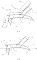
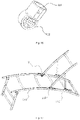
- the embodiment I of the present invention discloses a multifunctional chair, including a first frame body unit 1, a second frame body unit 2, a first supporting unit 3, and a first leaning unit 13 and a second leaning unit 23 respectively arranged on the first frame body unit 1 and the second frame body unit 2, where the first frame body unit 1 is provided with a head end 101 and a tail end 102, the first supporting unit 3 is connected with a first connecting position 103 of the first frame body unit 1 to support the first frame body unit 1, so that a height of the tail end 102 of the first frame body unit 1 is higher than the first connecting position 103, the first leaning unit 13 is arranged close to the first connecting position 103 and is mainly used to contact and support parts such as a hip and a leg, the second frame body unit 2 is arranged on a rear portion of the first frame body unit 1 and is rotatably connected with the first frame body unit 1, the multifunctional chair can move between a first posture as an inclining
- two using postures of the first posture as the inclining chair or the seat and the second posture as the fitness equipment can be obtained by adjusting an angular relation between the second frame body unit 2 and the first frame body unit 1, and the chair is multipurpose.
- the chair when the chair is adjusted to the second posture as the fitness equipment, it has the functions of fitness equipment, such as sit-up and push-up.
- the angle of the second frame body unit 2 relative to the first frame body unit 1 can be adjusted arbitrarily as needed, for example, when it is used as the seat at 90 degrees, as the inclining chair at 135 degrees, as the fitness equipment at 180 degrees and the like, and the demands on fitness or inclining chair or seat can be selected or switched anytime.
- a supporting frame of the multifunctional chair in the embodiment is composed of the first frame body unit 1 and the second frame body unit 2, the first frame body unit 1 and the second frame body unit 2 are provided with the first leaning unit 13 and the second leaning unit 23, the second frame body unit 2 is rotated relative to the first frame body unit 1, and the angle between the first leaning unit 13 and the second leaning unit 23 is adjusted therewith conveniently, so that fitness or inclining chair or seat is switched by one key.
- the structure of the multifunctional chair is simplified greatly, and it is simple and convenient to mount the chair and convenient to mount or detach the chair; the first frame body unit 1 and the second frame body unit 2 in the embodiment can be adjusted to an overlapped state.
- the integral structure of the multifunctional chair can be reduced, so that it is convenient to package, carry and transport the chair, and the cost is lowered greatly;
- the first frame body unit 1 and the second frame body unit 2 serve as the fitness equipment for sit-up, push-up and the like when being adjusted to the overlapped state, it has a relatively great stretching range for parts such as a leg, a waist, an abdomen, a back, a shoulder and a neck, and the second frame body unit 2 does not hinder the stretching action and various stretching actions can be performed freely;
- the first supporting unit 3 is connected with the first connecting position 103 of the first frame body unit 1, the height of the tail end 102 of the first frame body unit 1 is lower than the height thereof in the first connecting position 103, so that when the multifunctional chair is in the first posture of the inclining chair or the seat, the parts such as hip and leg can be attached to the first leaning unit 13 on the first frame body unit 1, and thus, the contact area between a human body and the first leaning
- the first posture for the inclining chair or the seat is that the second frame body unit 2 and the first frame body unit 1 have an angle
- the second posture for the fitness equipment is that the second frame body unit 2 is overlapped with the tail end of the first frame body unit 1.
- it can further be used as the fitness equipment when the second frame body unit 2 and the first frame body unit 1 have the angle, which also falls into the protection scope of the present invention.
- the first frame body unit 1 includes two frame body structures I 11 arranged in parallel; the frame body structures I 11 are arranged as rod-shaped structures; the first leaning unit 13 is mounted and supported between the two frame body structures I 11, so that the two frame body structures I 11 and the first leaning unit 13 jointly form a supporting end surface that is primarily used to support the parts such as hip and leg, and therefore, profiles needed by the first frame body unit 1 are saved greatly, the cost is saved, the overall weight of the multifunctional chair is alleviated, and it is convenient to use and carry; the two frame body structures I 11 are arranged in parallel, and compared with a structure that the frame body structures I 11 are not arranged in parallel, on the one hand, the integral size of the multifunctional chair is reduced, so that it is convenient to place, package, carry and transport; and on the other hand, widths of front and back ends of the two frame body structures I 11 are consistent, so that it is convenient to mount or connect the first leaning unit
- the frame body structure I 11 there may be one frame body structure I 11 that is arranged as a platy structure or a combination of three, four, five or even more rod-shaped structures with the first leaning unit 13 or is not provided with the first leaning unit 13 or is arranged as other frame body structures.
- the two frame body structures I 11 can further be arranged in an unparallel manner such as splay, inverted splay or intersection.
- the structures, with the first leaning unit 13, can also jointly form the supporting end surface for supporting the parts such as hip and leg.
- the frame body structure I 11 in the embodiment is made of metal materials such as steel and iron, so that the firmness of the structure is improved.
- the frame body structure I 11 can be further made of materials such as wood and plastics and other materials or made from a combination of the materials, so that the multifunctional chair is of more diversity.
- the first frame body unit 1 further includes two transverse supporting structures I 12 arranged between the first frame body structures I 11 at an interval, the transverse supporting structures I 12 are arranged as rod-shaped structures, and the first leaning unit 13 is mounted and supported above the first frame body structures I 11 and the transverse supporting structures I 12.
- the stability and bearing performance of the first frame body unit 1 and the first leaning unit 13 are improved.
- the two transverse supporting structures I 12 are arranged at an interval, so that profiles needed by the first frame body unit 1 are saved greatly, the cost is saved, the overall weight of the multifunctional chair is alleviated and it is convenient to use and carry the chair.
- the two transverse supporting structures I 12 may not be arranged.
- the two transverse supporting structures I 12 are arranged in parallel, so that a support-free space is formed between the two transverse supporting structures 112.
- the two transverse supporting structures I 12 can further be arranged in an unparallel manner such as splay and inverted splay or intersection, so that the stability and bearing performance of the first frame body unit 1 can further be improved.
- the transverse supporting structure I 12 in the embodiment is arranged as a downward concave arc-shaped structure, so that the attaching areas between the first leaning unit 13 and the parts such as hip and leg above the transverse supporting structure I 12 are further increased, and thus, the comfort levels of the parts such as hip and leg are further improved.
- the transverse supporting structure I 12 can be further arranged as an upward convex arc-shaped structure to improve the stretching range of the parts such as leg, waist, abdomen, back, shoulder and neck, or it is arranged as a straight body structure for supporting the parts such as hip and leg, too.
- the transverse supporting structure I 12 in the embodiment is made of metal materials such as steel and iron, so that the firmness of the structure is improved.
- the transverse supporting structure I 12 can be further made of materials such as wood and plastics and other materials or made from a combination of the materials, so that the multifunctional chair is of more diversity.
- the frame body structure I 11 is arranged as an integrated structure, so that the stability of the frame body structure I 11 is improved, and the frame body structure I is simple in structure and convenient to produce and machine.
- the second frame body unit 2 is connected with the first frame body unit 1 via the third rotating assembly 8, and the third rotating assembly 8 is configured to adjust and lock the position of the second frame body unit 2 between the first posture for the inclining chair or the seat and the second posture for the fitness equipment relative to the first frame body unit 1.
- the third rotating assembly 8 is arranged between the second frame body unit 2 and the first frame body unit 1, so that the angle and position between the second frame body unit 2 and the first frame body unit 1 can be adjusted and locked; the second frame body unit 2 is rotated relative to the first frame body unit 1, the angle between the first leaning unit 13 and the second leaning unit 23 is adjusted therewith, so that it is convenient to adjust and fitness equipment or inclining chair or seat is switched by one key.
- the structure of the multifunctional chair is simplified greatly, the weight of the multifunctional chair is alleviated, and it is convenient to use and carry the multifunctional chair and it is convenient to mount and detach the multifunctional chair.
- the third rotating assembly 8 can further be used to adjust the angle and position between the second frame body unit 2 and the first frame body unit 1 and is matched with other locking structures to lock the angle and position between the second frame body unit 2 and the first frame body unit 1, or the third rotating assembly 8 is merely used to lock the angle and position between the second frame body unit 2 and the first frame body unit 1 and is matched with other adjusting structures to adjust the angle and position between the second frame body unit 2 and the first frame body unit 1, so that the angle and position between the second frame body unit 2 and the first frame body unit 1 can be adjusted and locked, too.
- the second posture for the fitness equipment is formed in such a way that the second frame body unit 2 moves along the direction of the tail end of the first frame body unit 1 via rotation of the third rotating assembly 8 to be overlapped with the tail end 102 of the first frame body unit 1, and at the moment, the second leaning unit 23 further moves along with the second frame body unit 2 to be overlapped with the tail end 102, so that the integral multifunctional chair is in the structure of the fitness equipment for sit-up and push-up, and can be used for large-range stretching actions of the parts such as leg, waist, abdomen, back, shoulder and neck.
- the third rotating assembly 8 is arranged in a middle position of the first frame body unit 1, so that the second frame body unit 2 can be overlapped with the tail end 102 after moving along the direction of the tail end 102 of the first frame body unit 1, and therefore, it is ensured that the second leaning unit 23 and the first leaning unit 13 are distracted to the maximum range to form the maximum supporting end surface;
- the third rotating assembly 8 can be further arranged in a position that is a distance from the middle position relative to the first frame body unit 1, so that the second frame body unit 2 is overlapped with part of structure of the first frame body unit 1 close to the tail end 102 after moving along the direction of the tail end 102 of the first frame body unit 1 so as to form a slightly small supporting end surface, and it can be further switched between the first posture for the inclining chair or the seat and the second gesture for the fitness equipment.
- the second frame body unit 2 is arranged to be matched with the shape of the tail end 102 of the first frame body unit 1, so that the overlapping degree is higher without occupying extra space.
- the shapes of the tail ends 102 of the second frame body unit 2 and the first frame body unit 1 can further be arranged in different shapes, so that the two are just partially overlapped, and the second posture for the fitness equipment can be further formed.
- the first posture for the inclining chair or the seat is formed in such a way that the second frame body unit 2 rotates relative to the first frame body unit 1 via the third rotating assembly 8 and moves along any one direction of the tail end 102 or the head end 101 of the first frame body unit 1 to have an angle with the first frame body unit 1, and at the moment, the second leaning unit 23 further moves along with the second frame body unit 2 to have an angle with the tail end 102 of the first frame body unit 1, so that the integral multifunctional chair is in the structure of the inclining chair or the seat, and the second frame body unit 2 can be adjusted to a comfortable height as needed.
- the multifunctional chair when the multifunctional chair is in the first posture for the inclining chair or the seat, it can further be used for stretching actions of the parts such as leg, waist, abdomen, back, shoulder and neck.
- the second frame body unit 2 includes two frame body structures II 21 arranged in parallel; the frame body structures II 21 are arranged as rod-shaped structures; the second leaning unit 23 is mounted and supported between the two frame body structures II 21, so that the two frame body structures II 21 and the second leaning unit 23 jointly form a supporting end surface that is primarily used to support the parts such as back and waist, and therefore, profiles needed by the second frame body unit 2 are saved greatly, the cost is saved, the overall weight of the multifunctional chair is alleviated, and it is convenient to use and carry; the two frame body structures II 21 are arranged in parallel, and compared with a structure that the frame body structures II are not arranged in parallel, on the one hand, the integral size of the multifunctional chair is reduced, so that it is convenient to place, package, carry and transport; and on the other hand, widths of front and back ends of the two frame body structures II 21 are consistent, so that it is convenient to mount or connect the second leaning unit 23
- the frame body structure II 21 there may be one frame body structure II 21 that is arranged as a platy structure or a combination of three, four, five or even more rod-shaped structures with the second leaning unit 23 or is not provided with the second leaning unit 23 or is arranged as other frame body structures.
- the two frame body structures II 21 can further be arranged in an unparallel manner such as splay, inverted splay or intersection.
- the structures, with the second leaning unit can also jointly form the supporting end surface for supporting the parts such as back and waist.
- the frame body structure II 21 in the embodiment is made of metal materials such as steel and iron, so that the firmness of the structure is improved.
- the frame body structure II 21 can be further made of materials such as wood and plastics and other materials or made from a combination of the materials, so that the multifunctional chair is of more diversity.
- the second frame body unit 2 further includes two transverse supporting structures II 22 arranged between the frame body structures II 21 at an interval, the transverse supporting structures II 22 are arranged as rod-shaped structures, and the second leaning unit 23 is mounted and supported in front of the two frame body structures II 21 and the transverse supporting structures II 22.
- the stability and bearing performance of the second frame body unit 2 and the second leaning unit 23 are improved.
- the two transverse supporting structures II 22 are arranged at an interval, so that profiles needed by the second frame body unit 2 are saved greatly, the cost is saved, the overall weight of the multifunctional chair is alleviated and it is convenient to use and carry the chair.
- the two transverse supporting structures II 22 may not be arranged.
- the two transverse supporting structures II 22 are arranged in parallel, so that a support-free space is formed between the two transverse supporting structures II 22.
- the two transverse supporting structures II 22 can further be arranged in an unparallel manner such as splay and inverted splay or intersection, so that the stability and bearing performance of the second frame body unit 2 can further be improved.
- the transverse supporting structure II 22 in the embodiment is arranged as a backward concave arc-shaped structure, so that the attaching areas between the second leaning unit 23 in front of the transverse supporting structure II 22 and the parts such as back and waist are further increased, and thus, the comfort levels of the parts such as back and waist are further improved.
- the transverse supporting structure II 22 can be further arranged as a frontward convex arc-shaped structure to improve the stretching range of the parts such as leg, waist, abdomen, back, shoulder and neck, or it is arranged as a straight body structure for supporting the parts such as back and waist, too.
- the transverse supporting structure II 21 in the embodiment is made of metal materials such as steel and iron, so that the firmness of the structure is improved.
- the transverse supporting structure II 21 can be further made of materials such as wood and plastics and other materials or made from a combination of the materials, so that the multifunctional chair is of more diversity.
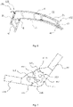
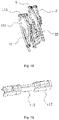
- the third rotating assembly 8 includes a ratchet wheel 812 with a ratchet wheel arm 811, a ratchet wheel shaft 813, a rotating arm 814, a check pawl 815, a check pawl shaft 816, a return piece 817 and a restoration piece 818, where the ratchet wheel arm 811 is connected with the frame body structure II 21 ; one end of the rotating arm 814 is hinged with the ratchet wheel 812 via a ratchet wheel shaft 813 and the other end thereof is connected with the frame body structure I 11; the check pawl 815 is hinged with the rotating arm 814 via a check pawl shaft 816 and is arranged corresponding to the ratchet wheel 812, and is used to resist rotation of the ratchet wheel 812; the return piece 817 is sleeved on the ratchet wheel shaft 813, one end of the return piece 817 is provided with
- the ratchet wheel 812 when the frame body structure II 21 rotates towards the direction of the head end 101, the ratchet wheel 812 further rotates therewith anti-clockwise, and meanwhile, the check pawl 815 streaks backs of teeth of the ratchet wheel 812 one by one.
- the check pawl 815 is returned to lean against a certain tooth space of the ratchet wheel 812 under elastic action of the restoration piece 818, so that the ratchet wheel 812 is locked, i.e., the frame body structure II 21 and the frame body structure I 11 are locked; and when it is needed to rotate the frame body structure II 21 towards the direction of the tail end 102, the frame body structure II 21 is rotated towards the direction of the tail end 102 first, so that the front side of the arc-shaped protrusion structure 8121 on the ratchet wheel 812 leans against the front side of the arc-shaped notch structure 8171 on the return piece 817, and the frame body structure II 21 is rotated continuously, so that the arc-shaped protrusion structure 8121 pushes the arc-shaped notch structure 8171 to rotate anti-clockwise until the lug structure 8172 pushes the ratchet pawl 835 away from the ratchet wheel 8
- the third rotating assembly 8 in the embodiment is simple in structure and easy to operate, so that the frame body structure II 21 connected with the ratchet wheel arm 811 can rotate and can be locked between the head end 101 and the tail end 102 of the frame body structure I 11 connected with the rotating arm 834.
- the third rotating assembly 8 can further be arranged in other ratchet wheel structures or hinged structures in which the frame body structure II 21 can rotate and can be locked between the head end 101 and the tail end 102 of the frame body structure I 11, and the frame body structure II 21 can further rotate and can be locked between the head end 101 and the tail end 102 of the frame body structure I 11.
- third rotating assemblies 8 there are two third rotating assemblies 8 in the embodiment and are respectively welded between the frame body structure II 21 and the frame body structure I 11 on the same side, so that the adjustability and the adjusting stability can be improved.
- the welding mode can be replaced by other connecting modes such as threaded connection, riveting connection, buckling connection and the like, and the third rotating assemblies 8 can further be arranged between any one or two of the frame body structure II 21 and the transverse supporting structures II 22 and any one or two of the frame body structure I 11 and the transverse supporting structures I 12, so that the second frame body unit 2 and the first frame body unit 1 are rotatably connected and locked.
- the first connecting position 103 is arranged close to the head end 11 close to the frame body structure I 11, i.e., the first supporting unit 3 is supported near the head end 101 of the frame body structure I 11, so that the integral height of the multifunctional chair is reduced and the integral stability of the multifunctional chair is improved.
- a distance is reserved between the head end 101 of the frame body structure I and the first connecting position 103, so that on the one hand, the connecting stability between the first supporting unit 3 and the frame body structure I 11 is improved and the falling connection risk is reduced, and on the other hand, the part of structure of the head end 101 of the frame body structure I 11 can further be used as a handrail, in particular used to assist the human body to perform various fitness actions such as sit-up and push-up when the multifunctional chair is in the second posture of the fitness equipment.
- the first leaning unit 13 is arranged on the frame body structure I 11 along the tail end 102 close to the first connecting position 103, so that the supporting end surface distracted between the first leaning unit 13 and the second leaning unit 23 is larger and has a larger contact area with human, the origins of force are more scattered, and therefore, the comfort level is improved.
- the first connecting position 103 can further be overlapped with the head end 101 of the frame body structure I 11, so that the overall height of the multifunctional chair is further reduced, and the integral stability of the multifunctional chair is improved.
- the head end 101 of the frame body structure I 11 is hidden in the first supporting unit 3, so that the multifunctional chair is more concise integrally and more barrier-free to use, or a position close to the head end 101 on a position close to the frame body structure I 11 is provided with another first connecting position 103 while the first connecting position 103 and the head end 101 of the frame body structure I 11 are overlapped, so that on a basis of conciseness and no barriers, the connecting stability of the first supporting unit 3 and the frame body structure I 11 is improved and the falling connection risk is reduced.
- the first connecting position 103 is arranged on the frame body structure I 11, so that the stability and the bearing performance of the multifunctional chair are improved.
- the first connecting position 103 can further be arranged on the transverse supporting structures I 12 or the frame body structure I 11 and the transverse supporting structures I 12, so that the first supporting unit 3 and the transverse supporting structures I 12 are connected or the frame body structure I 11 and the transverse supporting structures I 12 are connected jointly, and therefore, the first supporting unit 3 can support the head end 101 of the first frame body unit 1 or a position close to the head end 101, so that the height of the tail end 102 of the first frame body unit 1 is lower than the height of the first connecting position 103.
- first supporting unit 3 As shown in Fig. 1 , as an embodiment I of the present invention, there is one first supporting unit 3, so that it is simple in structure and convenient to use, carry and transport. Certainly, in some other embodiments, there are two, three or even more first supporting unit 3 to enhance support to the first frame body unit 1, so that the stability and the bearing performance of the multifunctional chair are improved.
- the first supporting unit 3 is arranged at an angle with mounting end surfaces such as a floor, a ground mat, gravel and various indoor or outdoor platform surfaces, i.e., the first supporting unit 3 is arranged obliquely relative to the mounting end surfaces.
- the upper end of the first supporting unit 3 is arranged inclining backwards, so that the multifunctional chair forms a gradually contracted structure from bottom to top integrally. All parts of the multifunctional chair are more compact when the first frame body unit 1 is stressed, so that it is more stable and firm in structure.
- the upper end of the first supporting unit 3 can further be arranged inclining forwards, so that the multifunctional chair forms a gradually contracted structure from bottom to top integrally, and parts such as feet and shank can move in a barrier-free manner, or the first supporting unit 3 is arranged perpendicular to the mounting end surfaces to further form stable triangular supporting structures with the first frame body unit 1 and the mounting end surfaces such as the ground, so that the multifunctional chair is placed and used stably.
- the first supporting unit 3 includes two parallelly arranged first supporting pieces 31, the first supporting pieces 31 are arranged in rod-shaped structures, and the upper ends of the two first supporting pieces 31 are respectively connected with the first connecting position 103 of the frame body structure I 11 on the same side and the lower ends thereof lean against the mounting end surfaces of mounting media such as the floor, the ground mat, the gravel and various indoor or outdoor platforms, so that profiles needed by the first supporting unit 31 are greatly saved, the cost is saved, the overall weight of the multifunctional chair is alleviated and it is convenient to use and carry.
- the two first supporting pieces 31 are arranged in parallel and are arranged in splayed shapes relatively.
- the overall volume of the multifunctional chair is reduced, so that it is convenient to place, package, carry and transport.
- the two first supporting pieces 31 and the frame body structure I 11 on the same side are located on a same plane, and a backward forward supporting force is applied to the frame body structures I 11 on the same side, so that the supporting stability is improved.
- the two first supporting pieces 31 can further be arranged in such an unparallel manner of splayed and inverted splayed shapes or arranged in an intersected manner, so that the two first supporting pieces 31 are respectively connected with the frame body structures I 11 on the opposite side, which can further support the first connecting positions 103 on the first frame body units 1 by the first supporting unit 3.
- the first supporting piece 31 in the embodiment is made of metal materials such as steel and iron.
- the first supporting piece 31 can be further made of materials such as wood and plastics and other materials or made from a combination of the materials, so that the multifunctional chair is of more diversity.
- the first supporting piece 31 is arranged as an integrated structure, so that the stability of the first supporting unit 3 is improved, and it is simple in structure and convenient to produce and machine.
- the first supporting unit 3 is rotatably connected with the first frame body unit 1 via the first rotating assembly 6, so that the first supporting unit 3 can rotate relative to the first frame body unit 1.
- the angle between the mounting end surface of the first supporting unit 3 relative to the ground and the overall height of the multifunctional chair are changed, so that the supporting direction of the first frame body unit 1 by the first supporting unit 3 is changed to form different supporting structures.
- the positioning unit 9 can move therewith, so that the angle when it is used as a foot mat or a presser foot is different, and therefore, the multifunctional chair is richer in using state.
- the first supporting unit 3 after the first supporting unit 3 is rotated to lean against the first frame body unit 1, the first supporting unit 3 can further be folded, so that the integral volume of the multifunctional chair is reduced, and it is convenient to store, package, carry and transport.
- the first supporting piece 31 and the frame body structure I 11 on the same side are connected via one first rotating assembly 6, so that the two first supporting pieces 31 rotate respectively relative to the frame body structure I 11 on the same side to combine more diversified using states.
- the two supporting pieces 31 can be folded, so that the integral volume of the multifunctional chair is further reduced, and it is convenient to store, package, carry and transport.
- the first rotating assembly 6 includes a connector I 61, a rotating shaft I 62 and a limiting piece I 63, where one end of the connector I 61 is connected with the first connecting position 103 on the frame body structure I 11 while the other end thereof is hinged to the first supporting pieces 31 via the rotating shaft I 62, so that the first supporting piece 31 can rotate relative to the first connecting position 103 on the frame body structure 111.
- the rotating shaft I 62 is arranged perpendicular to the direction of the frame body structure I 11, and the limiting piece I 63 is arranged on the front portion of the connector I 61, so that the rotating trajectories of the two first supporting pieces 31 are defined in a parallel direction of the frame body structure I 11, thereby preventing instability of the multifunctional chair due to inconsistence of the rotating angles and the directions of the two first supporting pieces 31.
- the multifunctional chair when the first supporting unit 3 is rotated forwards to the front end of the first supporting piece 31 relative to the first frame body unit 1 to lean against the limiting piece I 63, i.e., the first supporting unit 3 is unfolded under drive by the first supporting piece 31, at the time, the multifunctional chair can be placed on the mounting end surfaces such as ground to use.
- the first supporting unit 3 is rotated backwards to the first frame body unit 1 relative to the first frame body unit 1 to lean against the first frame body unit 1, i.e., the first supporting unit 3 is folded and contracted under drive of the first supporting piece 31, at the time, the integral volume of the multifunctional chair is reduced and it is convenient to store, package, carry or transport.
- a locking piece can further be arranged to lock the first supporting piece 31 at any angle rotating relative to the connector I 61, so that the first supporting piece 31 and the first frame body unit 1 are integrally fixed to different angles and positions for foot mats or presser feet at different angles and positions, and thus, the multifunctional chair is richer in using state.
- the first rotating assembly 6 can further be arranged in other connecting structures such as a hinge in such a manner that the first supporting piece 31 rotates relative to the frame body structure I 11 and the first frame body unit 1 is converted between the unfolded state and the contracted state, so that it is convenient to use, store, package, carry or transport.
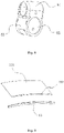
- the multifunctional chair further includes a positioning unit 9 arranged on the first supporting unit 3.
- a positioning unit 9 arranged on the first supporting unit 3.
- the multifunctional chair When the multifunctional chair is in the first state of the reclining chair or the seat, it can further be used for placing parts such as feet and shanks, so that the sitting or lying comfort level is improved.
- the multifunctional chair In the second posture of the fitness equipment, it can be further used for placing or positioning one of the feet and shanks, or placing or positioning the feet and shanks simultaneously to assist various stretching actions of legs, waist, abdomen, back, shoulders, neck and the like. It replaces existing independent fitness equipment completely.
- the positioning unit 9 includes two positioning connectors 91 and a positioning adjusting piece 92, where the positioning connectors 91 are arranged in rod-shaped structures and the two positioning connectors 91 are arranged at an interval. Two ends of the two positioning connectors 91 are respectively connected with two first supporting pieces 31.
- the two positioning connectors 91 and the two first supporting pieces 31 jointly form leaning end surfaces for placing or positioning parts such as legs and shanks, so that profiles needed by the positioning unit 9 are saved greatly, the cost is saved, the integral weight of the multifunctional chair is alleviated, and it is convenient to use and carry.
- the two positioning connectors 91 are arranged at an interval, so that the parts such as legs and shanks can be placed butane the two positioning connectors 91 to limit and support front and back two contact surfaces, so that the positioning stability is improved.
- the two positioning connectors 91 are connected between the two first supporting pieces 31 to further enhance the stability of the first supporting unit 3.
- the two first supporting pieces 31 are respectively sleeved with the positioning adjusting pieces 92, and the outer ends of the positioning adjusting pieces 92 are formed with positioning end surfaces leaning against the parts such as legs and shanks, so that the contact area between the two positioning pieces 91 and the parts such as legs and shanks is increased, and the comfort level is improved.
- positioning connectors 91 which are respectively sleeved with the positioning adjusting pieces 92, so that the parts such as legs and shanks and the positioning unit 9 have two placing or positioning end surfaces, and therefore, the comfort level and the positioning stability are improved.
- the positioning adjusting pieces 92 can be merely sleeved on a certain positioning connector 91 or several certain positioning connectors 91 to be combined or there are no positioning adjusting pieces 92, which can also be used for placing or positioning the parts such as legs and shanks.
- fixed connection structures such as welding and riveting structures can be adopted between the positioning connectors 91 and the first supporting pieces 31, so that the stability of the structure is improved.
- Detachable connection structures such as threaded structures, screws and dowels can be adopted, too, so that the multifunctional chair is converted between a condition with the positioning unit and a condition without the positioning unit, and therefore, the multifunctional chair is more diversified.
- Rotatable connection structures are adopted, so that the positioning connectors 91 can rotate relative to the first supporting pieces 31 to massage the parts such as legs and shanks, thereby enriching the functionality of the multifunctional chair.
- fixed connection structures such as welding and gluing structures can be adopted between the positioning connectors 91 and the first supporting pieces 31, so that the stability of the structure is improved.
- Detachable connection structures such as clamping connection structures, threaded structures, and interference fitting connection structures can be adopted, too, so that the multifunctional chair is converted between a condition with the positioning adjusting pieces and a condition without the positioning adjusting pieces, and therefore, the multifunctional chair is more diversified.
- Rotatable connection structures are adopted, so that the positioning adjusting pieces 92 can rotate relative to the positioning connectors 91 to massage the parts such as legs and shanks, thereby enriching the functionality of the multifunctional chair.
- the positioning connectors 91 in the embodiment are made of metal materials such as steel and iron, so that the firmness of the structure is improved.
- the positioning connectors 91 can be further made of materials such as wood and plastics and other materials or made from a combination of the materials, so that the multifunctional chair is of more diversity.
- the positioning adjusting pieces 92 are arranged as flexible structures such as a sponge body, a foam body and a soft silica structure, so that the comfort levels of the parts such as legs and shanks placed or positioned on the positioning adjusting pieces 92 are further enhanced.
- the positioning adjusting pieces 92 can further be arranged in hard structures such as steel, iron, plastics and hard silica gel and can further increase the contact area between the two positioning connectors 91 and the parts such as legs and shanks, so that the comfort level is improved properly.
- the multifunctional chair further includes a second supporting unit 4 for supporting the rear portion of the first frame body unit 1 so as to keep balance of the integral multifunctional chair.
- the second supporting unit 4 is formed by the tail end 102 of the first frame body unit 1, so that the structure is simplified, and it is convenient to produce and machine.
- the second supporting unit 4 can further be formed by the main body on the first frame body unit 1 close to the tail end 102 and the tail end 102 jointly, i.e., is formed by the first frame body unit 1 which is larger, or is merely formed by the main body on the first frame body unit 1 close to the tail end 102, or is independently arranged with the second supporting unit 4 and is connected with the tail end 102 of the first frame body unit 1 or a position close to the tail end 102, to further support the rear portion of the first frame body unit 1 to keep balance of the integral multifunctional chair.
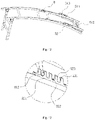
- the second supporting unit 4 As shown in Fig. 4 , as an embodiment I of the present invention, there is one second supporting unit 4, so that it is simple in structure and convenient to use, carry and transport. Certainly, in some other embodiments, there are two, three or even more second supporting unit 4 to enhance support to the rear portion of the first frame body unit 1, so that the stability and the bearing performance of the multifunctional chair are improved.
- the second supporting unit 4 is arranged at an angle with mounting end surfaces such as a floor, a ground mat, gravel and various indoor or outdoor platform surfaces, i.e., the second supporting unit 4 is arranged obliquely relative to the mounting end surfaces.
- the upper end of the second supporting unit 4 is arranged inclining backwards, so that the multifunctional chair forms a gradually contracted structure from bottom to top integrally. All parts of the multifunctional chair are more compact when the first frame body unit 1 is stressed, so that it is more stable and firm in structure.
- the second supporting unit forms an extended shape of the first frame body unit 1 due to the angle of the upper end of the second supporting unit 4 inclining forwards, so that it is simple in structure and easy to produce and machine, and can form the stable triangular supporting structures with the first frame body unit 1, the first supporting unit 3 and the mounting end surface such as ground, and therefore, the multifunctional chair is placed and used stably.
- the upper end of the second supporting unit 4 can further be arranged inclining forwards, so that the multifunctional chair forms a gradually contracted structure from bottom to top integrally, and the tail end 102 of the first frame body unit 1 and the mounting end surfaces such as ground have a certain height, so that it can move below the tail end 102 of the first frame body unit 1 in a barrier-free manner, or the second supporting unit 4 is arranged perpendicular to the mounting end surfaces to support the front and rear ends of the frame body unit 1 with the first supporting unit 3 jointly, so that the multifunctional chair is placed and used stably.
- the second supporting unit 4 includes two parallelly arranged second supporting pieces 41, the second supporting pieces 41 are arranged as rod-shaped structures, the second supporting pieces 41 are respectively formed by the frame body structures I 11 on the same side, and the lower ends of the second supporting pieces 41 lean against the mounting end surfaces of mounting media such as the floor, the ground mat, the gravel and various indoor or outdoor platforms, so that profiles needed by the second supporting unit 41 are greatly saved, the cost is saved, the overall weight of the multifunctional chair is alleviated and it is convenient to use and carry.
- the two second supporting pieces 41 are arranged in parallel and are arranged in splayed shapes relatively.
- the overall volume of the multifunctional chair is reduced, so that it is convenient to place, package, carry and transport.
- the two second supporting pieces 41 and the frame body structure I 11 on the same side are located on a same plane, and a backward forward supporting force is applied to the frame body structures I 11 on the same side, so that the supporting stability is improved.
- the two second supporting pieces 41 can further be arranged in such an unparallel manner of splayed and inverted splayed shapes or arranged in an intersected manner, so that the two second supporting pieces 41 are respectively connected with the frame body structures I 11 on the opposite side, which can further support the rear portion of the first frame body unit 1 by the second supporting unit 4.
- the second supporting piece 41 in the embodiment is made of metal materials such as steel and iron, so that the firmness of the structure is improved.
- the second supporting piece 41 can be further made of materials such as wood and plastics and other materials or made from a combination of the materials, so that the multifunctional chair is of more diversity.
- the second supporting piece 41 is arranged as an integrated structure, so that the stability of the second supporting unit 4 is improved, and it is simple in structure and convenient to produce and machine.
- the second supporting unit 4 further includes a first reinforcing piece 42 between the two second supporting pieces 41 for enhancing the stability and the bearing performance of the structure of the second supporting unit 4.
- the second reinforcing piece 42 is arranged as the rod-shaped structure, so that profiles needed by the second reinforcing piece 42 is saved greatly, the cost is saved, the overall weight of the multifunctional chair is alleviated, and it is convenient to use and carry.
- the rod body structure can be replaced by a platy structure or other structures, which may realize an effect of enhancing the stability and the bearing performance of the structure of the second supporting unit 4.
- the second reinforcing pieces 42 are arranged between the tail ends o f the two supporting pieces 41, so that the contact areas between the second supporting units 4 and the mounting end surfaces such as ground are increased, and the stability of placing the chair is improved.
- the second reinforcing pieces 42 are arranged between other position of the two supporting pieces 41, which may realize an effect of enhancing the stability and the bearing performance of the structure of the second supporting unit 4.
- the second reinforcing piece 41 in the embodiment is made of metal materials such as steel and iron, so that the firmness of the structure is improved.
- the second reinforcing piece 41 can be further made of materials such as wood and plastics and other materials or made from a combination of the materials, so that the multifunctional chair is of more diversity.
- the multifunctional chair further includes a handrail structure 14.
- the handrail structure 14 is sleeved outside the head end 101 of the frame body structure I 11, so that the contact area when the head end 101 of the frame body structure I 11 is grasped by a hand is increased, and therefore, the using comfort level is improved, in particular, it is favorable to assist the human body to perform various fitness actions such as sit-up and push-up when the multifunctional chair is in the second posture of the fitness equipment.
- the handrail structure 14 is arranged outside the head end 101 of the frame body structure I 11, so that it is favorable to mount, detach and use and convenient to produce and machine.
- the handrail structure 14 can further be arranged on other positions of the frame body structure I 1, or can be arranged on any one of or a combination of several of the transverse supporting structures I 12, the first leaning unit 13, the first rotating assemblies 6, the first supporting pieces 31, the positioning connectors 91, the positioning adjusting pieces 92, the frame body structures II 21, the transverse supporting structures II 22 or the second leaning unit 23, which may realize an effect of assisting the human body to perform various fitness actions such as sit-up and push-up.
- the handrail structure 14 is in flexible structures such as a sponge body, a foam body or a soft silica gel structure, so that the grasping comfort level is improved.
- the handrail structure 14 can further be in rigid structures such as a steel body, an iron body and a body, so that the using comfort level can be properly improved.
- the handrail structure 14 is rotatably connected with the head end 101 of the frame body structure I 11, and the handrail structure 14 can rotate relative to the frame body structure I 11 after being grasped, so that it is convenient to assist the human body to perform various fitness actions such as hand and wrist twisting, and therefore, the fitness effect is improved.
- the handrail structure 14 can further be connected with the head end 101 of the frame body structure I 11 via fixed connection structures such as welding, gluing connection structures, so that the connecting stability is improved, or via detachable connection structures such as thread connection structures, screw connection structures, clamping connection structures and interference fitting connection structures, which is convenient to replace handrail structures 14 of different types.
- the first leaning unit 13 includes a first leaning structure 131, the first leaning structure 131 is mainly used for contacting and supporting the parts such as hip and legs when the human body sits or lies down, the first leaning structure 131 is arranged on the frame body structure I 11, and the first leaning structure 131 is formed by extending along the direction close to the tail end 102 of the first frame body unit 1 from the rear end close to the first connecting position 103.
- the front end of the first leaning structure 131 is arranged close to the first connecting position 103 supported by the first supporting piece 31, so that the first leaning structure 131 is located between the first connecting position 103 on the frame body structure I 11 and the first rotating assembly 6 in a large area, so that it is ensured that the first leaning structure 131 has an contact end surface large enough and is not intersected with the first connecting position 103 or the first rotating assembly 6, and therefore, it is convenient to mount and detach.
- a suspending space is reserved between the front end of the first leaning structure 131 and the positioning unit 4 to place and position the parts such as legs and shanks
- a suspending space is reserved between the front end of the first leaning structure 131 and the handrail structure 14 to place the parts such as legs and shanks
- the parts such as legs and shanks are blocked in the suspending space via the handrail structure 14 to further position the parts such as legs and shanks, and collision to the parts such as legs and shanks by the outer side can be prevented.
- the front end of the first leaning structure 131 can further be arranged on the first connecting position 103, can further reserve the suspending space for placing and positioning the parts such as legs and shanks on a basis of ensuring that the first leaning unit 13 has the contact end surface large enough, or is formed by extending along the direction close to the tail end 102 of the first frame body unit 1 from the front end close to the first connecting position 103.
- the rear end of the first leaning structure 131 can further be arranged in a position on the frame body structure I 11 connected with the first rotating assembly 6, or is arranged behind the position on the frame body structure I 11 connected with the first rotating assembly 6 and is even arranged at the tail end 102 of the first frame body unit 1, which can further support the parts such as hip and legs by the first leaning unit 3.
- the first leaning structure 131 can further be arranged on the transverse supporting structures I 12, or is arranged on the frame body structure I 11 and the transverse supporting structures I 12, which can further support the parts such as hip and legs.
- the first leaning structure 131 is connected with the frame body structure I 11 via the first connecting assembly 132, so that the first leaning structure 131 is detachably connected to the frame body structure I 11, and therefore, it is convenient to clean the first leaning structure 131, or the first leaning structures 131 of different types can be replaced according to different demands, so that the multifunctional chair is more diversified.
- the frame body structure I 11 is provided with a groove type structure with an opening.
- the first connecting assembly 132 is arranged in a clamping strip structure matched with the groove type structure.
- the first leaning structure 131 is in buckling connection with the groove type structure on the frame body structure I 11 via the clamping strip structure, so that it is convenient to mount and detach.
- the groove type structure and the clamping strip structure can further be arranged in other buckling structures or any one detachable connection structure such as a hook structure and a pasting structure or a combination of several detachable connection structures, so that it is convenient to clean and replace the first leaning structures 131 of different types.
- Part of or all structures of the end portion of the first leaning structure 131 are wrapped outside the frame body structure I 11 and are connected with the frame body structure I 11, so that the structure is simplified and it is convenient to produce and machine.
- the second leaning unit 23 includes a second leaning structure 231, the second leaning structure 231 is mainly used to contact and support the parts such as back and waist of the human body sitting or lying, the second leaning structure 231 is arranged on the frame body structure II 21, and is formed by extending along the direction close to the other end of the frame body structure II 21 from an end close to the frame body structure II 21.
- two ends of the second leaning structure 231 are arranged close to two ends of the frame body structure II 21 respectively, so that the second leaning structure 231 is arranged on the frame body structure II 21 in a large area, and therefore, it is ensured that the second leaning structure 231 has the contact end surface large enough, and it is convenient to mount and detach.
- the second leaning structure 231 can further be arranged in part of regions on the frame body structure II 21, so that the second leaning structure 231 has the contact end surface relatively small, and the leaning structure 231 can support the parts such as hip and legs.
- the second leaning structure 231 can further be arranged on the transverse supporting structures II 22, or is arranged on the frame body structure II 21 and the transverse supporting structures II 22, which can further support the parts such as hip and waist.
- the second leaning structure 231 is connected with the frame body structure II 21 via the second connecting assembly 232, so that the second leaning structure 231 is detachably connected to the frame body structure II 21, and therefore, it is convenient to clean the second leaning structure 231, or the second leaning structures 231 of different types can be replaced according to different demands, so that the multifunctional chair is more diversified.
- the frame body structure II 21 is provided with a groove type structure with an opening.
- the second connecting assembly 232 is arranged in a clamping strip structure matched with the groove type structure.
- the second leaning structure 231 is in buckling connection with the groove type structure on the frame body structure II 21 via the clamping strip structure, so that it is convenient to mount and detach.
- the groove type structure and the clamping strip structure can further be arranged in other buckling structures or any one detachable connection structure such as a hook structure and a pasting structure or a combination of several detachable connection structures, so that it is convenient to clean and replace the second leaning structures 231 of different types.
- Part of or all structures of the end portion of the second leaning structure 231 are wrapped outside the frame body structure II 21 and are connected with the frame body structure I 11, so that the structure is simplified and it is convenient to produce and machine.
- the first leaning structure 131 and the second leaning structure 231 are arranged as cloth structures, so that the cost is lowered.
- the cloth structures can be made from elastic materials, so that the flexibility when the human sits or lies down is improved.
- the cloth structures can further be made from non-elastic materials, so that the hardness when the human sits or lies down is improved.
- the cloth structures can further be replaced by any one of or a combination of several of other structures such as leather structures, bamboo structures, rattan structures, plastic structures and wooden structures, which may contact and support the parts such as hip, legs, back and waist when the human body sits or lies down, and the multifunctional chair is more diversified.
- other structures such as leather structures, bamboo structures, rattan structures, plastic structures and wooden structures, which may contact and support the parts such as hip, legs, back and waist when the human body sits or lies down, and the multifunctional chair is more diversified.
- the frame body structure I 11 is arranged as the upward-convex arc-shaped structure, in particular the upward-convex arc-shaped structure gradually descending along the direction of the tail end 102 along the first connecting position 103 of the frame body structure I 11;
- the frame body structure II 21 is arranged as the upward-convex arc-shaped structure matched with the tail end 102 of the frame body structure I 11;
- the first leaning unit 13 is formed by extending along the direction of the tail end 102 from a position close to the first connecting position 103, when the multifunctional chair is in the first posture of the reclining chair or the seat, the human body can integrally sit on or lie down the first leaning unit 13 and the second leaning unit 23 arranged on the first frame body unit 1 and the second frame body unit 2 obliquely backwards, so that the whole body is pressure-relieved and relaxed.
- the parts such as hip, legs, back and waist better fit the first leaning unit 13 and the second leaning unit 23, and the force bearing points are further scattered, and the human body feel more comfortable and relaxed;
- the multifunctional chair is in the second posture of the fitness equipment, the human body can lie on the first leaning unit 13 and the second leaning unit 23 arranged on the first frame body unit 1 and the second frame body unit 2 in an integral gradual descending posture from the edge of the first connecting position 103 close to the first leaning unit 13 to perform fitness actions such as sit-up.
- the fitness strength is enhanced, and the fitness effect is improved, i.e., the stretching amplitude of the parts such as legs, waist, abdomen, back, shoulders and neck is increased, the fitness effect is improved; and it is in the gradual descending posture integrally, so that it better meets the human body structure, and it is more comfortable to perform fitness actions such as sit-up.
- the frame body structure I 11 can further be arranged such that a certain position between the first connecting position 103 and the tail end 102 is higher than the upward-convex arc-shaped structure of the first connecting position 103, so that when the multifunctional chair is in the first posture of the reclining chair or the seat, only the upper part of the body and the hip and the like of the human body sits or lies down on the first leaning unit 13 and the second leaning unit 23 arranged on the first frame body unit 1 and the second frame body unit 2 obliquely backwards, so that a certain pressure relieving and relaxing function is realized.
- the human body can enable the parts such as the half part of the body and the hip to lie down on the first leaning unit 13 and the second leaning unit 23 arranged on the first frame body unit 1 and the second frame body unit 2 in the gradual descending posture to perform fitness actions such as sit-up.
- the fitness strength can be enhanced and existing independent fitness equipment is replaced, or the frame body structure I 11 can further be arranged as a straight body structure.
- the attaching area can be increased to a certain extent, and therefore, the comfort level is improved.
- the relative angle between the first leaning unit 13 on the frame body structure I 11 and the second leaning unit 23 on the frame body structure II 21 is equal to 180 degrees, so that the stretching amplitude of the parts such as legs, waist, abdomen, back, shoulders and neck is increased compared with the prior art, and the fitness effect is improved.
- the multifunctional chair further includes a third supporting unit 5, where the third supporting unit 5 is arranged on the lower rear side of the second frame body unit 2, and the lower end of the third supporting unit 5 leans against the first frame body unit 1.
- the third supporting unit 5 supports and further locks the rear portion of the second supporting unit 2, so that the stability and the bearing performance of the second frame body unit 2 are further enhanced when the multifunctional chair is in the first posture of the reclining chair or the seat, the second frame body unit 2 is prevented from rotating backwards after being stressed after the parts such as back and waist lean against the second frame body unit 2, and a supporting force towards the upper front side is applied to the rear portion of the second frame body unit 2, so that it is more forward and direct to support the second frame body unit 2 after being stressed by the third supporting unit 5, and therefore, the supporting effect is better.
- the third supporting unit 5 can further be arranged right below or on the front lower side of the second frame body unit 2 or directions combining the several directions, so as to apply right-above and rear-above supporting forces or tensile forces to the second frame body unit 2, so that the stability and the bearing performance of the second frame body unit 2 when the multifunctional chair is in the first posture of the reclining chair or the seat can be enhanced.
- the lower end of the third supporting unit 5 can further lean against the second supporting unit 4, which also has an equivalent effect.
- the third supporting piece 51 can be rotatably connected with the frame body structure I 11, too, and the third adjusting assembly 52 is arranged on the frame body structure II 21, which also has an equivalent effect.
- the third supporting unit 5 includes the third supporting piece 51 and the third adjusting assembly 52, where the upper end of the third supporting piece 51 is rotatably connected with movable ends of the two frame body structures II 21 respectively and the lower end thereof is adjustably connected with the third adjusting assembly 52, so that the third supporting piece 51 can rotate relative to the frame body structures 1121 at the connecting position with the frame body structures II 21.
- the lower end of the rotated third supporting piece 51 is connected with a new position of the third adjusting assembly 52 after the third adjusting assembly 52 is adjusted, so that the supporting angle of the third supporting piece 51 to the frame body structures II 21 is adjusted, and therefore, different distracting angles between the second leaning unit 23 on the frame body structure II 21 and the first leaning unit 13 on the frame body structures I 11 are supported.
- There are two third adjusting assemblies 52 and the two third adjusting assemblies 52 are correspondingly arranged on the two frame body structures I 11 to adjust the position of the lower end of the third supporting piece 51 relative to the two frame body structures I 11.
- a fixed connection structure such as welding and riveting connection structures can be adopted between the third adjusting assembly 52 and the frame body structure 111, so that the connecting stability is enhanced.
- a detachable connection structure such as a threaded structure, a screw and a buckle can be further adopted, so that it is convenient to assembly or replace.
- the third adjusting assembly 52 can further be arranged on the second supporting piece 41 or the second reinforcing piece 42 or a combination of several parts, which also has the equivalent effect.
- the third adjusting assembly 52 includes an adjusting piece III 521, the adjusting piece III 521 is provided with several adjusting channels III 522, each of the adjusting channels III 522 is arranged to be matched with the lower end of the third supporting piece 51 to connect, lock and support the lower end of the third supporting piece 51 so as to improve the stability of the third supporting unit 5 on the frame body structures II 21, and meanwhile, the adjusting channel III 522 is arranged to be matched with the rotating angel of the third rotating assembly 8, so that when a distracting angle between the second leaning unit 23 on the frame body structure II 21 and the first leaning unit 13 on the frame body structure I 11 is locked at any angle of the third rotating assembly 8, there is one adjusting channel III 522 corresponding to the lower end of the third supporting piece 51 supported with the frame body structure II 21 at an angle at the time on the adjusting piece III 521, so that the second frame body unit 2 is supported and locked under a condition that each angle is locked.
- the adjusting channel III 522 can further be arranged to be merely matched with the part of rotating angle of the third rotating assembly 8, so that the third supporting unit 5 is merely used for further support at the part of distracting angle between the second leaning unit 23 on the frame body structure II 21 and the first leaning unit 13 on the frame body structure I 11, so that the supporting stability to the frame body structure II 21 by the third supporting unit 5 can be improved.
- the adjusting channel III 522 is arranged as a groove type structure opened in the upper end.
- the third supporting piece 51 includes two supporting pieces III 511 and a clamping piece III 512, where the upper ends of the two supporting pieces III 511 are rotatably connected with the two frame body structures II 21 via hinging pieces 513 and the lower ends thereof are respectively connected with positions of the clamping piece 512 close to two end portions.
- the clamping piece III 512 between the position where the two supporting pieces III 511 are connected with the clamping piece III 512 and two end portions of the clamping piece III 512 is used for clamping connection with the groove type structure, so that the lower end of the third supporting piece 51 is supported and locked in a certain adjusting channel III 522.
- the groove type structure is arranged to be matched with the structure of the area between the end portion of the clamping piece III 512 and the position connected with the third supporting piece III 511 to enhance the supporting stability of the third adjusting assembly 52 to the lower end of the third supporting piece 51.
- the clamping piece III 512 is integrally arranged as the cylindrical rod-shaped structure.
- the groove type structure is arranged as a corresponding U-shaped groove structure, so that it is convenient to clamp the clamping piece III 512 from each angle and direction into the adjusting channel III 522 from the opening, and it is easy to operate, simple in structure and easy to produce and machine.
- the structure of the area from the end portion to the position connected with the third supporting piece III 511 is merely arranged as the cylindrical structure by the clamping piece III 512 but the structure of the area between the positions connected with the two supporting pieces III 511 is arranged as other structures such as square structures and polygonal structures, so that it is further convenient to clamp the clamping piece III 512 into the adjusting channel III 522 from each angle and direction from the opening, or the clamping piece III 512 is arranged as other structures such as square structures and polygonal structures matched with the groove type structure, or other structures not matched with the groove type structure, so that the lower end of the third supporting piece 51 can further be supported and locked in a certain adjusting channel III 522.
- the opening of the groove type structure is formed by the clamping portion I 523 and the clamping portion II 524 at an interval; an interval width between the clamping portion I 523 and the clamping portion II 524 is smaller than the width of the groove type structure, and the clamping portion I 523 and the clamping portion II 524 are made from slightly elastic materials, so that after the end portion of the clamping piece III 512 is clamped into the groove type structure, the clamping piece III 512 is firmly defined in the groove type structure by means of the clamping portion I 523 and the clamping portion II 524 to prevent looseness.
- the clamping portion I 523 slightly protrudes outside the inner side of the groove type structure, the clamping portion II 524 further protrudes outside the inner side of the groove type structure relatively, i.e., the end portion of the clamping piece III 512 is defined by the clamping portion II 524, so that when the frame body structure II 21 rotates along a direction of the head end 101 or the tail end 102 of the frame body structure I 11, it drives the third supporting piece 51 to move forwards or backwards relative to the third adjusting assembly 52, i.e., two ends of the clamping piece III 512 are respectively separated from a certain adjusting channel III 522 and slide along the upper end surfaces of several clamping portions I 523 and clamping portions II 524, and after the frame body structure II 21 is adjusted to a needed angle, the frame body structure II 21 or the third supporting piece 51 is pressed downwards, the clamping piece III 512 is stressed to be clamped into another adjusting channel III 522, so that it is simpler to operate and more convenient to use.
- the opening of the groove type structure can further be arranged as other structures which are narrower than the groove type structure, and the clamping piece III 512 can further be firmly defined in the groove type structure to prevent looseness.
- the third supporting unit 5 it is only necessary to separate the clamping piece III 512 from the adjusting piece III 521, and the third supporting unit 5 can be folded and contracted behind the second frame body unit 2 by rotating the hinge piece III 513 relative to the frame body structure II 21 without affecting use of the multifunctional chair as the seat, the reclining chair or the fitness equipment.
- the third supporting piece 51 in the embodiment is made of metal materials such as steel and iron, so that the firmness of the structure is improved.
- the third supporting piece 51 can be further made of materials such as wood and plastics and other materials or made from a combination of the materials, so that the multifunctional chair is of more diversity.
- the third supporting unit 5 in the embodiment can further be used in other embodiments, so that the multifunctional chairs in other embodiments further have the effect.
- the third rotating assembly 8 includes the connector III 821 and the rotating shaft 822, where the connector III 821 is connected with the frame body structure II 21, and one end of the rotating shaft III 822 is connected with the frame body structure I 11 and the other end thereof is rotatably connected with the connector III 821.
- structures such as the ratchet wheel arm 811, the ratchet wheel 812, the ratchet wheel shaft 813, the rotating arm 814, the check pawl 815, the check pawl shaft 816, the return piece 817 and the restoration piece 818 in the embodiment II are replaced by the connector III 821 and the rotating shaft 822, so that the structure is simplified, and therefore, it is convenient to produce and machine.
- the connector III 821 can rotate in an omnibearing manner at 360 degrees relative to the rotating shaft 822.
- the second frame body unit 2 When the multifunctional chair is in the first posture of the reclining chair or the seat, the second frame body unit 2 can be rotated in a barrier-free manner along the direction of the head end 101 or the tail end 102 of the first frame body unit 1 and the rotated angle and position are locked via the third supporting piece 5, so that the second frame body unit 2 is fixed relative to the distracted angle of the first frame body unit 1, and therefore, the distracted angle range of the frame body structure II 21 relative to the frame body structure I 11 is enlarged. It is easy to operate, wide in using range and suitable for more crowds. Certainly, a fixed connection structure such as welding and riveting connection structures can be adopted between the connector III 821 and the frame body structure II 21 and between the rotating shaft III 822 and the frame body structure I 11, so that the connecting stability is enhanced.
- a detachable connection structure such as a screw and a buckle can be further adopted, so that it is convenient to assembly or replace.
- the frame body structure II 21 and the frame body structure I 11 can be rotatably connected directly through the rotating shaft or other hinge structures, so that the second frame body unit 2 can be rotated in a barrier-free manner at 360 degrees relative to the direction of the head end 101 or the tail end 102 of the first frame body unit 1.
- the connector III 821 can be connected with the frame body structure I 11, too, and the rotating shaft 822 is connected with the frame body structure II 21, which also has an equivalent effect.
- the third rotating unit 8 in the embodiment can further be used in other embodiments, so that the multifunctional chairs in other embodiments further have the effect.
- the difference between the embodiment IV and the embodiment III lies in that the frame body structure I 11 is arranged as a split structure, including a frame body portion 1111 and a frame body portion II 112, where the frame body portion II 112 and the frame body portion I 111 are pivotably connected, and the frame body portion II 112 can be rotated relative to the frame body portion I 111, so that an angle formed between the frame body portion I 111 and the frame body portion II 112 is changed.
- the frame body portion II 112 when the frame body portion II 112 is rotated relative to the frame body portion I 111 to lean against the frame body portion I 111, the frame body portion II 112 can be folded and contracted, so that on a basis of folding and contracting the first supporting unit 3 and the positioning unit 9 of the multifunctional chair in the embodiment III, the frame body portion II 112 is further folded and contracted, and the multifunctional chair is fully folded and contracted completely, and therefore, the integral volume of the multifunctional chair is reduced greatly, and it is more convenient to store, package, carry or transport.
- the frame body portion II 112 When the frame body portion II 112 is rotated to an original state relative to the frame body portion I 111, the frame body portion II 112 can be unfolded to use.
- a pivotal connector between the frame body portion I 111 and the frame body portion II 112 can be a pivotal connector which enables the frame body portion II 112 to be rotatably contracted relative to the frame body portion I 111 and to form the upward-convex arc-shaped structure of the original frame body structure I 11 when being unfolded to use.
- the pivotal connector in the embodiment is the pivotal structure I 113, where the pivotal structure I 113 includes a frame body portion III 115 and two pivotal connectors I 114 hinged to two ends of the frame body portion III 115, so that the frame body portion I 111 and the frame body portion II 112 can be respectively hinged with the two pivotal connectors I 114 and are respectively folded and contracted relative to the two ends of the frame body portion III 115.
- the folded and contracted multifunctional chair is more compact in structure in the embodiment, so that conditions that the first frame body unit 1 is resisted, is unsmoothly contracted and the like in the folding and contracting process due to its own structure are avoided.
- the frame body portion III 115 is arranged in a shape of the frame body structure I 11, so that the frame body structure I 11 with the foldable and contractible effect still keeps the upward-convex arc shape on the original frame body structure I 11, and has the using effect, for the first posture of the reclining chair or the seat and the second posture of the fitness equipment, similar with that of the original frame body structure I 11.
- the frame body portion III 115 can further be arranged in other shapes, such as downward-convex arc shapes or straight rod shapes, different from those of the frame body structure I 11, so that conditions that the first frame body unit 1 is resisted, is unsmoothly contracted and the like in the folding and contracting process due to its own structure are avoided.
- the frame body portion II 112 can be folded and contracted below the frame body portion I 111.
- the frame body structure I 11 is arranged as the upward-convex arc-shaped structure, the folded and contracted multifunctional chair is more compact in structure, and damage caused by collision in storing, packaging or transporting processes can be prevented.
- the frame body structure II 21 can rotate in a barrier-free manner at 360 degrees relative to the frame body structure I 11, the second frame body unit 2 and the third supporting unit 5 can be folded and contracted below the frame body portion I 111, so that the integral volume of the multifunctional chair is further decreased.
- the folded and contracted transverse supporting structures I 12 and transverse supporting structures II 22 can be placed in a staggered manner, so that the folded and contracted multifunctional chair is more compact in structure, the integral volume of the multifunctional chair is decreased again, and it is more convenient to store, package, carry or transport.
- the frame body portion I 111 and the frame body portion 112 can further be merely connected via one pivotal connector I 114, so that the frame body portion II 112 can be folded and contracted below the frame body portion I 111.
- the frame body portion II 112, the second frame body unit 2 and the third supporting unit 5 can be folded and contracted above the frame body portion I 111, so that the integral volume of the multifunctional chair is decreased again, and it is more convenient to store, package, carry or transport.
- there is only one pivotal structure I 113 so that the frame body structure I 11 can be integrally folded and contracted.
- the frame body structure I can further be provided with two, three or even more pivotal structures I 113, so that the frame body structure I 11 has three-folded, four-folded or even more-fold contracting effect.
- the frame body portion I 111 can be connected with the frame body portion II 112 via a telescopic structure.
- the integral volume of the multifunctional chair can further be reduced by way of decreasing the overall length of the frame body structure I 11, and it is more convenient to store, package, carry or transport.
- the frame body structure I 11 in the embodiment can further be used in other embodiments, so that the multifunctional chair in other embodiments further has the effect.
- the third rotating assembly 8 can be connected with any one of or a combination of several of the frame body portion I 111, the frame body portion II 112, the pivotal structure I 113 or the second supporting piece 41, and the second frame body unit 2 is rotatably connected relative to the first frame body unit 1, so that the multifunctional chair has two using states: the first posture for the reclining chair or the seat or the second posture for the fitness equipment.
- a multifunctional chair As shown in Fig. 20-Fig. 21 , as an embodiment V of the present invention, disclosed is a multifunctional chair.
- the difference between the embodiment V and the embodiment I lies in that the frame body structure I 11 is provided with the pivotal structure I 113 in the embodiment IV; as the rotating angle between the ratchet wheel arm 811 and the rotating arm 814 is limited in a certain range, the second frame body unit 2 and the third supporting unit 5 are folded and contracted above the frame body portion I 111.
- the integral volume of the multifunctional chair is reduced, and it is more convenient to store, package, carry or transport.
- the first supporting piece 31 is arranged as the spilt structure, including the first supporting portion 311 and the second supporting portion 312, where the first supporting piece 31 is directly connected with the first connecting position 103 on the frame body structure I 11 and is not connected via the first rotating assembly 6, the second supporting portion 312 is pivotably connected with the first supporting portion 311, and the second supporting portion 312 can be rotated relative to the first supporting portion 311, so that the angle formed between the first supporting portion 311 and the second supporting portion 312 is changed.
- the second supporting portion 312 when the second supporting portion 312 rotates to the lower side of the frame body portion 1111 relative to the first supporting portion 311 to lean against the frame body portion I, the second supporting portion 312 can further be folded contracted, so that the integral volume of the multifunctional chair is reduced, and it is more convenient to store, package, carry or transport.
- the second supporting portion 312 rotates to the original state relative to the first supporting portion 311, the second supporting portion 312 can be unfolded to use.
- the pivotal structure II 313 between the first supporting portion 311 and the second supporting portion 312 is a hinge structure which is simple in structure and convenient to assemble and use.
- the pivotal structure II 313 can further be other pivotal connectors capable of rotatably contracting the second supporting portion 312 relative to the first supporting portion 311 and forming the shape and structure of the original first supporting piece 31 when being unfolded and used, where the second supporting portion 312 can be switched between the folded and contracted state and the unfolded state.
- the lower end of the first supporting portion 311 in the embodiment is arranged close to the first connecting position 103, and the positioning connector 91 is only arranged on the second supporting portion 312, so that the folded and contracted second supporting portion 312 is closer to the frame body structure I 11, and therefore, the folded and contracted multifunctional chair is integrally more compact.
- the lower end of the first supporting portion 312 can further be arranged slightly far away from the first connecting position 103.
- the positioning connector 91 can further be arranged on the first supporting portion 311 and the second supporting portion 312 or is only arranged on the first supporting portion 311, so that the second supporting portion 312 is rotatably contracted relative to the first supporting portion 311 to be switched between the folded and contracted state and the unfolded state.
- the connecting end between the first supporting portion 311 and the second supporting portion 312 is further provided with the positioning protrusion, and the connecting end of the second supporting portion 312 is correspondingly provided with the positioning groove for positioning the unfolded second supporting portion 312, so that the connecting stability is enhanced, and conditions of twisting, deflecting and the like of the first supporting portion 311 or the second supporting portion 312 are prevented.
- the first supporting piece 31 in the embodiment is made of a wood material, so that the feeling of comfort is enhanced.
- the first supporting piece 31 can further be made of metal materials such as steel and iron or a plastic material or made from other materials or a combination of the materials, so that the multifunctional chair is of more diversity.
- the first supporting piece 31 in the embodiment can further be used in other embodiments, so that the multifunctional chairs in other embodiments further have the effect.
- the difference II between the embodiment VI and the embodiment IV lies in that the first supporting piece 31 is arranged as a structure that is narrow on the upper side and wide on the lower side.
- the rod structure in the embodiment IV is replaced, so that there is a larger contact area between the lower end surface of the first supporting piece 31 and the mounting end surface such as ground, and therefore, the integral stability and bearing performance of the multifunctional chair are improved.
- the first supporting piece 31 in the embodiment can further be used in other embodiments, so that the multifunctional chairs in other embodiments further have the effect.
- the difference III between the embodiment VI and the embodiment IV lies in that the second supporting unit 4 is connected with the main body of the first supporting unit 3 close to the tail end 102 and the tail end 102, i.e., the second supporting unit 4 integrated with the frame body structure I 11 in the embodiment IV is replaced by the independent second supporting unit 4, the second supporting unit 4 comprises two second supporting pieces 41 respectively connected with the main body of the frame body structure I 11 close to the tail end 102 and the tail end 102 and a second reinforcing piece 42 arranged between the second supporting pieces 41, and the second supporting pieces 41 are arranged as structures that are narrow on the upper side and wide on the lower side, the rod structure in the embodiment IV is replaced, so that there is a larger contact area between the lower end surface of the first supporting piece 41 and the mounting end surface such as ground, and therefore, the integral stability and bearing performance of the multifunctional chair are improved.
- the second supporting piece 41 is connected with the main body of the frame body structure I 11 close to the tail end 102 and the tail end 102, so that the contact area of the connecting area is increased and the connecting stability is improved.
- the second supporting piece 41 can further be connected with the tail end 102 of the frame body structure I 11 or the position close to the tail end 102 independently.
- the second supporting piece 41 and the frame body structure I 11 can be connected via the fixed connection structure such as welding and riveting structures, so that the connecting stability is improved. They can further be connected via the detectable connection structures such as screws and buckles, so that it is convenient to mount and detach.
- the second supporting piece 41 in the embodiment is made of a wood material, so that the feeling of comfort is enhanced.
- the second supporting piece 41 can further be made of metal materials such as steel and iron or a plastic material or made from other materials or a combination of the materials, so that the multifunctional chair is of more diversity.
- the second supporting piece 41 in the embodiment can further be used in other embodiments, so that the multifunctional chairs in other embodiments further have the effect.
- the third supporting unit 5 includes an upper third supporting piece 531 and a lower third supporting piece 532, where the upper end of the upper third supporting piece 531 is rotatably connected with the frame body structure II 21, the upper end of the lower third supporting piece 532 is in fit connection with the upper third supporting piece 531, and the lower end of the lower third supporting piece 532 is separably connected with the frame body structure I 11.
- the upper third supporting piece 531 and the lower third supporting piece 532 in the embodiment replace the third supporting piece 51 and the third adjusting assembly 52 in the embodiment IV.
- the upper third supporting piece 531 and the lower third supporting piece 532 are matched structurally to support the frame body structure II 21 at each angle.
- the lower end of the lower third supporting piece 532 can further be movably connected with the frame body structure I 11 via and adjustable structure.
- the frame body structure II 21 at each angle is supported jointly by the adjustable structure or the adjustable structure combined with a matching structure of the upper third supporting piece 531 and the lower third supporting piece 532.
- the lower end of the third supporting piece 532 can further be connected with the second supporting unit 4, which also has an equivalent effect.
- the upper third supporting piece 531 and the lower third supporting piece 532 are arranged as telescopic structures.
- a connecting end III 5321 is gradually contracted and hidden in a mounting channel III 5311, i.e., the height of the second frame body unit 2 relative to a mounting section such as ground is reduced, and the angle of the second frame body unit 2 relative to the first leaning unit 13 is decreased.
- the lower third supporting piece 532 is gradually stretched and unfolded relative to the upper third supporting piece 531, i.e., the height of the second frame body unit 2 relative to the mounting end surface such as ground is increased and the angle of the second frame body unit 2 relative to the first leaning unit 13 is decreased, so that it is easy to operate and convenient to use.
- the upper third supporting piece 531 and the lower third supporting piece 532 can further be in fit connection by using other adjustable structures such as a slide rail structure and a buckling structure, and the frame body structure II 21 at each angle can be supported by changing the overall lengths of the upper third supporting piece 531 and the lower third supporting piece 532.
- the upper third supporting piece 531 and the lower third supporting piece 532 in the embodiment are made of metal materials such as steel and iron, so that the firmness of the structure is improved.
- the upper third supporting piece 531 and the lower third supporting piece 532 can be further made of materials such as wood and plastics and other materials or made from a combination of the materials, so that the multifunctional chair is of more diversity.
- the third supporting unit 5 in the embodiment can further be used in other embodiments, so that the multifunctional chairs in other embodiments further have the effect.
- the difference II between the embodiment VII and the embodiment IV lies in that the first supporting piece 31 is arranged as the split structure, including the first supporting portion 311 and the second supporting portion 312, where the upper end of the second supporting portion 312 is in fit connection with the lower portion of the first supporting portion 311, and the lower end surface thereof leans against the mounting end surface of the mounting media of a floor, a ground mat, gravel and various indoor or outdoor platforms, so that the overall length of the first supporting portion 311 and the second supporting portion 312 is changed, i.e., the height of the first connecting position 103 on the frame body structure I 11 relative to the mounting end surface such as ground can be changed.
- the first supporting piece 31 of the integrated structure in the embodiment IV is replaced by the first supporting piece 31 of the split structure including the first supporting portion 311 and the second supporting portion 312.
- the first connecting position 103 of the frame body structure I 11 is supported at the first supporting piece 31 and on a basis that the first supporting piece 31 can be folded and contracted below the frame body structure I 11 via the first rotating assembly 6 relatively, the length of the first supporting piece 31 can further be adjusted to adjust the height of the overall height of the multifunctional chair, so that the multifunctional chair is richer in using state and a wider application range.
- the second supporting portion 312 and the first supporting portion 311 are arranged as telescopic structures.
- the overall height of the multifunctional chair can be adjusted by changing the overall length of the second supporting portion 312 and the first supporting portion 311, and it is easy to operate and convenient to use.
- the first supporting portion 311 and the second supporting portion 312 can also be in fit connection by using other adjustable structures such as a slide rail structure and a buckling structure, and the overall height of the multifunctional chair can further be adjusted by changing the overall length of the first supporting portion 311 and the second supporting portion 312.
- the lengths of the first supporting portion 311 and the second supporting portion 312 in the embodiment are substantially consistent
- the two positioning connectors 91 are respectively arranged between the two first supporting portions 31 and the two second supporting portions 312, so that the overlapped lengths of the contracted first supporting portions 31 and second supporting portions 312 are greater, and the sum of the lengths of the unfolded first supporting portions 31 and second supporting portions 312 is greater, and therefore, the overall height adjusting range of the multifunctional chair is large by the first supporting piece 31.
- the interval between the two positioning connectors 91 is increased or decreased therewith to place or position parts such as feet and shanks with different intervals.
- the lengths of the first supporting portion 311 and the second supporting portion 312 can further be arranged at a relatively large interval.
- the two positioning connectors 91 can further be merely arranged on the first supporting portion 311 or the second supporting portion 312, so that the overall height of the multifunctional chair can be adjusted by changing the overall lengths of the first supporting portion 311 and the second supporting portion 312.
- the first supporting portion 311 and the second supporting portion 312 in the embodiment are made of metal materials such as steel and iron, so that the firmness of the structure is improved.
- the first supporting portion 311 and the second supporting portion 312 can be further made of materials such as wood and plastics and other materials or made from a combination of the materials, so that the multifunctional chair is of more diversity.
- the first supporting piece 31 in the embodiment can further be used in other embodiments, so that the multifunctional chairs in other embodiments further have the effect.
- the difference III between the embodiment VII and the embodiment IV lies in that the second supporting piece 41 is arranged as the split structure, including the third supporting portion 411 and the fourth supporting portion 412, where the upper end of the fourth supporting portion 412 is in fit connection with the lower portion of the third supporting portion 411, and the lower end surface thereof leans against the mounting end surface of the mounting media of a floor, a ground mat, gravel and various indoor or outdoor platforms, so that the overall length of the third supporting portion 411 and the fourth supporting portion 412 is changed, i.e., the height of the rear end of the frame body structure I 11 relative to the mounting end surface such as ground can be changed.
- the second supporting piece 41 of the integrated structure in the embodiment IV is replaced by the second supporting piece 41 of the split structure including the third supporting portion 411 and the fourth supporting portion 412.
- the fourth supporting portion 412 By matching the fourth supporting portion 412 with the third supporting portion 411 structurally, on a basis that the second supporting piece 41 supports the rear end of the frame body structure I 11, the length of the second supporting piece 41 can further be adjusted to adjust the height of the rear end of the multifunctional chair, so that the multifunctional chair is richer in using state and a wider application range.
- the fourth supporting portion 412 and the third supporting portion 411 are arranged as telescopic structures.
- the height of the rear end of the multifunctional chair can be adjusted by changing the overall length of the fourth supporting portion 412 and the third supporting portion 411, and it is easy to operate and convenient to use.
- the third supporting portion 411 and the fourth supporting portion 412 can also be in fit connection by using other adjustable structures such as a slide rail structure and a buckling structure, and the height of the rear end of the multifunctional chair can further be adjusted by changing the overall length of the third supporting portion 411 and the fourth supporting portion 412.
- the second reinforcing pieces 42 in the embodiment are arranged between the tail ends of the two fourth supporting portions 412, so that the contact areas between the second supporting units 4 and the mounting end surfaces such as ground are increased, and the stability of placing the chair is improved.
- the second reinforcing pieces 42 further connect the second supporting pieces 41 on two sides integrally, facilitating integral folding or stretching of the second supporting unit 4 relative to the first frame body unit 1.
- the second reinforcing pieces 42 can further be arranged between other positions of the two fourth supporting portions 412 or between the two third supporting portions 411, so that the structural stability and the bearing performance of the second supporting unit 4 are enhanced.
- the third supporting portion 411 and the fourth supporting portion 412 in the embodiment are made of metal materials such as steel and iron, so that the firmness of the structure is improved.
- the third supporting portion 411 and the fourth supporting portion 412 can be further made of materials such as wood and plastics and other materials or made from a combination of the materials, so that the multifunctional chair is of more diversity.
- the second supporting piece 41 in the embodiment can further be used in other embodiments, so that the multifunctional chairs in other embodiments further have the effect.
- the difference IV between the embodiment VII and the embodiment IV lies in that the second supporting unit 4 is rotatably connected with the first frame body unit 1 via the second rotating assembly 7.
- the second supporting unit 4 can rotate relative to the first frame body unit 1.
- the angle between the second supporting unit 4 and the mounting end surface such as ground and the overall height of the multifunctional chair are changed, so that the supporting direction of the first frame body unit 1 by the second supporting unit 4 is changed to form different supporting structures, and therefore, the multifunctional chair is richer in using state.
- the second supporting unit 4 after the second supporting unit 4 is rotated to lean against the first frame body unit 1, the second supporting unit 4 can further be folded, so that more folding and contracting modes are provided for the multifunctional chair.
- the second supporting piece 41 and the frame body structure I 11 on the same side are connected via one second rotating assembly 7, and are driven by the second reinforcing piece 42 to rotate relative to the frame body structure II 11 on the same side, so that it is convenient to fold and contract the second supporting unit 4 independently.
- the second rotating assembly 7 includes a connector II 71, a rotating shaft II 72 and a limiting piece II 73, where one end of the connector II 71 is connected with the frame body structure I 11 via the rotating shaft II 72 while the other end thereof is hinged to the second supporting piece 41 via the other rotating shaft II 72, so that the second supporting piece 41 can rotate relative to the connecting position on the frame body structure I 11.
- the rotating shaft II 72 is arranged perpendicular to the direction of the frame body structure I 11, and the limiting piece II 73 is arranged on the front portion of the connector II 71, so that the rotating trajectories of the two second supporting pieces 41 are defined in a parallel direction of the frame body structure I 11, thereby preventing instability of the multifunctional chair due to inconsistence of the rotating angles and the directions of the two second supporting pieces 41.
- the multifunctional chair when the second supporting unit 4 is rotated backwards to the top end of the second supporting piece 41 relative to the first frame body unit 1 to lean against the limiting piece II 73, i.e., the second supporting unit 4 is unfolded under drive by the second supporting piece 41, at the time, the multifunctional chair can be placed on the mounting end surfaces such as ground to use.
- the second supporting unit 4 is rotated forwards to the first frame body unit 1 relative to the first frame body unit 1 to lean against the first frame body unit 1, i.e., the second supporting unit 4 is folded and contracted under drive of the second supporting piece 41, at the time, the integral volume of the multifunctional chair is reduced and it is convenient to store, package, carry or transport.
- a locking piece can further be arranged to lock the second supporting piece 41 at any angle rotating relative to the connector II 71, so that second first supporting piece 41 and the first frame body unit 1 are integrally fixed to different angles and positions for support at different angles and positions, and thus, the multifunctional chair is richer in using state.
- the second rotating assembly 7 can further be arranged as other connecting structures such as a hinge in such a manner that the second supporting piece 41 rotates relative to the frame body structure I 11 and the second supporting unit 4 is converted between the unfolded state and the contracted state, so that it is convenient to use, store, package, carry or transport.
- pivotal connector I 114 in the embodiment IV or the pivotal connector II 313 in the embodiment VI can further be a structure of the second rotating assembly 7 in the embodiment.
- the second rotating unit 7 in the embodiment can further be used in other embodiments, so that the multifunctional chairs in other embodiments further have the effect.
Landscapes
- Health & Medical Sciences (AREA)
- General Health & Medical Sciences (AREA)
- Orthopedic Medicine & Surgery (AREA)
- Physical Education & Sports Medicine (AREA)
- Dentistry (AREA)
- Engineering & Computer Science (AREA)
- Biomedical Technology (AREA)
- Neurology (AREA)
- Pulmonology (AREA)
- Special Chairs (AREA)
- Chairs For Special Purposes, Such As Reclining Chairs (AREA)
Abstract
Description
- The invention relates to the field of daily necessities, in particular to a multifunctional chair.
- A recliner is a chair with a long backrest and tilted backwards. People can lie on it to rest, with the improvement of people's living standards, recliners have become popular leisure products in many places such as homes, offices, public places, and outdoors. The existing recliners are mostly composed of a seat and a seat back that is inclined to the seat. Although it can be used for people to lie down and rest on it to meet people's daily needs, it has a single function and no fitness function.
- The Chinese patent is authorized to announce a utility model patent for a folding fitness recliner Announcement Number:
CN202858399U ), which includes a backing board, an armrest, a sitting board, a footrest, a foot board support, an X-shaped chair support and a connecting frame. Among them, the backing board Connected with the seat board, the stepping board and the seat board are movably and telescopically connected. There is a multi-position card slot plate in the card-position armrest. One end of the card slot plate extends out of the armrest and is connected to the side of the backing board. There is a movable support under the armrest. The rod is twisted with the connecting frame, and the upper end of the movable support rod is provided with clamping nails and the card slot; the rods on the two upper ends of the chair support are movably connected with the elongated slots provided on both sides of the connecting frame, and the foot board support and the step board Stranded connection; also includes pulley, presser foot bending rod, tension spring, pulley support rod; the upper end of the pulley support rod is twisted with the middle part of the back of the backing plate, and the lower end is fixedly connected with the middle point of the coupling shaft of a pair of pulleys; the lower part of the back of the backing plate is provided The tension spring is connected with the lower end of the pulley support rod; the two ends of the bending rod of the presser foot are movably connected with the two outer ends of the footboard. - The patent adds foldable and fitness functions to the traditional recliner chair, which is more effective in use, but still has the following shortcomings: (1) There are many components, the structure is complex, and the overall chair is relatively bulky and inconvenient to use, package, and Carrying and transportation; (2) The front and rear height of the chair seat is the same. When the chair is in the recliner state, only the hips fit the seat seat and the comfort is not high; the seat back and seat cannot be adjusted to the support range required for fitness. When using for fitness, it is inconvenient to use, and even affects the stretching of legs, waist, abdomen, back, shoulders, neck and other parts; (3) When switching the recliner to the fitness state, the foot support, X The chair supports are folded one by one, and the bending bar of the presser foot is bent upward. The operation is complicated, time-consuming and labor-intensive.
- Aiming at the deficiencies in the prior art, the present invention provides a multifunctional chair with multiple functions, which is also used for seats, recliners and fitness equipment, and has simple structure, simple and fast operation, convenient use, and easy to carry and transport.
- The specific technical solutions are as follows:
- A multifunctional chair, comprising:
- a first frame body unit, the first frame body unit being provided with a head end and a tail end;
- a first supporting unit configured to support the first frame body unit, the first supporting unit being connected with a first connecting position of the first frame body unit and a height of the tail end of the first frame body unit being lower than a height of the first connecting position;
- a first leaning unit arranged in a position of the first frame body unit close to the first connecting position;
- a second frame body unit arranged on a back portion of the first frame body unit, the second frame body unit and the first frame body unit being rotatably connected, the second frame body unit and the first frame body unit in rotatable connection being capable of moving between a first posture of a reclining chair or a seat and a second posture of fitness equipment, the second frame body unit and the first frame body unit being in the first posture when having an angle, and the second frame body unit and the first frame body unit being in the second posture when the tail ends of the second frame body unit and the first frame body unit are overlapped; and
- a second leaning unit arranged on the second frame body unit.
- Further technical solutions, wherein the first frame body unit comprises a frame body structure I arranged in parallel, the frame body structure I is configured to mount and support the first leaning unit.
- Further technical solutions, wherein the first frame body unit comprises a frame body structure I and transverse supporting structures I arranged in parallel, the transverse supporting structures I are arranged on the frame body structure I at an interval, the frame body structure I and the transverse supporting structures I are configured to mount and support the first leaning unit, the frame body structure I and/or the transverse supporting structures I are arranged as a rod-shaped structure, and the frame body structure I is arranged as an upward-convex arc-shaped structure.
- Further technical solutions,, wherein the frame body structure I is arranged as an integrated structure.
- Further technical solutions,, wherein the frame body structure I is arranged as a split structure, comprising:
- a frame body portion I; and
- a frame body portion II pivotably connected with the frame body portion I via a pivotal structure I, the pivotal structure I comprising a frame body portion III and at least two pivotal connectors I hinged to two ends of the frame body portion III, the frame body portion I and the frame body portion II being respectively hinged with the the pivotal connectors I and being respectively folded, and contracted relative to two ends of the frame body portion III to change an angle formed between the frame body portion I and the frame body portion II, thereby unfolding and folding states of the frame body portion I and the frame body portion II being adjusted.
- Further technical solutions, , wherein the second frame body unit is connected with the first frame body unit via a third rotating assembly, and is configured to adjust a first posture and/or a second posture in position of the second frame body unit relative to the first frame body unit and/or lock the second frame body unit in the first posture and/or the second posture, the third rotating assembly is arranged in a middle position of the first frame body unit, and the second frame body unit is arranged to be matched with a shape of the tail end of the first frame body unit;
- the second posture is formed in such a way that the second frame body unit moves along the direction of the tail end of the first frame body unit via rotation of the third rotating assembly to be overlapped with the tail end of the first frame body unit; and
- the first posture is formed in such a way that the second frame body unit moves along any one direction of the head end or the tail end of the first frame body unit via rotation of the third rotating assembly to have an angle with the first frame body unit.
- Further technical solutions, wherein the second frame body unit comprises a frame body structure II arranged in parallel, the frame body structure II is configured to mount and support the second leaning unit.
- Further technical solutions, wherein the second frame body unit comprises a frame body structure II and transverse supporting structures II arranged in parallel, the transverse supporting structures II are arranged on the frame body structure II at an interval, the frame body structure II and the transverse supporting structures II are configured to mount and support the second leaning unit, the frame body structure II and/or the transverse supporting structures II are arranged as a rod-shaped structure, and the frame body structure II is arranged as an upward-convex arc-shaped structure matched with the tail end of the frame body structure I.
- Further technical solutions,, wherein the third rotating assembly comprises:
- a ratchet wheel with a ratchet wheel arm, the ratchet wheel arm being connected with the frame body structure II and/or the transverse supporting structures II;
- a rotating arm, one end thereof being hinged with the ratchet wheel via a ratchet wheel shaft and the other end thereof being connected with the frame body structure I and/or the transverse supporting structures I;
- a check pawl hinged with the rotating arm via a check pawl shaft and arranged corresponding to the ratchet wheel for resisting rotation of the ratchet wheel;
- a return piece sleeved on the ratchet wheel shaft, one end of the return piece being provided with an arc-shaped notch structure, the ratchet wheel being provided with an arc-shaped protrusion structure corresponding to the arc-shaped notch, and the other end of the return piece being provided with a lug structure corresponding to the check pawl to drive the check pawl to leave the ratchet wheel; and
- a restoration piece for restoring the check pawl.
- Further technical solutions,, wherein the third rotating assembly comprises:
- a connector III connected with the frame body structure II; and
- a rotating shaft III, one end thereof being connected with the frame body structure I and the other end thereof being connected with the connector III.
- Further technical solutions,, further comprising a third supporting unit for supporting the second frame body unit, the third supporting unit being arranged on a lower rear side of the second frame body unit, the third supporting unit comprising:
a third supporting piece, an upper end of the third supporting piece being rotatably connected with the frame body structure II, the third supporting piece comprising two supporting pieces III and a clamping piece III, and the upper ends of the two supporting pieces III being rotatably connected with the two frame body structures II via hinging pieces III respectively and the lower ends thereof being connected to positions of the clamping piece III close to two end portions, respectively; and - At least two third adjusting assemblies, the third adjusting assemblies being correspondingly arranged on the two frame body structures I to adjust the position of the third supporting piece relative to the first frame body unit, each of the third adjusting assemblies comprising an adjusting piece III, the adjusting piece III being provided with several adjusting channels III, each of the adjusting channels III being arranged to be matched with the lower end of the third supporting piece, the adjusting channels III being arranged as trough structures opened in the upper ends, and the clamping piece III between a position where the two supporting pieces III and the clamping piece III are connected and two end portions of the clamping piece III is connected with the trough structure in a clamping manner to support and lock the lower end of the third supporting piece in a certain adjusting channel III.
- Further technical solutions,, wherein the first connecting position is arranged close to the head end of the first frame body unit and/or is arranged overlapped with the head end of the first frame body unit, there is at least one first supporting unit, the first supporting unit is arranged at an angle with a mounting end surface, the upper end of the first supporting unit is arranged obliquely backwards, the first supporting unit comprises at least two first supporting pieces arranged in parallel, each of the first supporting pieces is arranged as a rod-shaped structure or a structure that is narrower on the upper portion and wider on the lower portion, and the upper end of the first supporting piece is connected with the first connecting position of the first frame body unit and the lower end of the first supporting piece leans against the mounting end surface of a mounting medium.
- Further technical solutions,, wherein the first supporting piece is arranged as an integrated structure, and the first supporting unit is rotatably connected with the first frame body unit via a first rotating assembly, the first rotating assembly comprising:
- a connector I connected with the first connecting position on the frame body structure I;
- a rotating shaft I, one end thereof being hinged with the first supporting piece while the other end thereof being connected with the connector I, the rotating shaft I being arranged perpendicular to a direction of the frame body structure I; and
- a limiting piece I arranged on a front portion of the connector I, the first supporting unit being rotated forwards relative to the first frame body unit to the front end of the first supporting piece to lean against the limiting piece I so as to unfold the first supporting unit, and the first supporting unit being rotated by the first frame body unit to lean against the first frame body unit so as to fold and contract the first supporting unit.
- Further technical solutions,, wherein the first supporting piece is arranged as a split structure, comprising:
- a first supporting portion, a lower end of the first supporting portion being arranged close to the first connecting position; and
- a second supporting portion pivotably connected with the first supporting portion , change an angle between the first supporting portion and second supporting portion, thereby the unfolding and folding states of the first supporting portion and the second support being adjusted, the second supporting portion being capable of folding and contracting the second supporting portion when rotating relative to the first supporting portion to lean against the lower side of the frame body portion I, the second supporting portion being capable of unfolding the second supporting portion when rotating relative to the second supporting portion to an original state, connecting ends of the first supporting portion and the second supporting portion being further provided with positioning protrusions, and the connecting end of the second supporting portion being correspondingly provided with a positioning groove to position the unfolded second supporting portion.
- Further technical solutions,, further comprising a positioning unit arranged on the first supporting unit, wherein when the multifunctional chair is in the second posture, the positioning unit is configured for placing and/or positioning a foot or a leg of a human body, the positioning unit comprising:
- at least two positioning connectors arranged at an interval, the positioning connectors being arranged as rod-shaped structures at an interval, two ends of the positioning connectors being respectively connected with a first supporting piece; and/or
- positioning adjusting pieces sleeved on the positioning connectors, the outer ends of the each of the positioning adjusting pieces being formed with a positioning end surface for the foot or the leg of the human body to lean against and the positioning adjusting piece being arranged as a flexible structure.
- Further technical solutions,, further comprising a second supporting unit, wherein the second supporting unit is connected with the tail end of the first frame body unit and/or is connected with a main body close to the tail end.
- Further technical solutions,, further comprising a second supporting unit, wherein the second supporting unit is composed of the tail end of the first frame body unit and/or a main body of the first frame body unit close to the tail end.
- Further technical solutions,, wherein there is at least one second supporting unit, the second supporting unit is arranged at an angle with the mounting end surface, the upper end of the second supporting unit is arranged obliquely forwards, the second supporting unit comprises at least two second supporting pieces arranged in parallel, each of the second supporting pieces is arranged as a rod-shaped structure or a structure that is narrower on the upper portion and wider on the lower portion, the upper end of the first supporting piece is connected with the first frame body unit and the lower end of the first supporting piece leans against the mounting end surface of a mounting medium, the two second supporting pieces are respectively located on a same plane with the frame body structure I on the same side, the second supporting unit further comprises at least one second reinforcer arranged between the two second supporting pieces, and the second reinforcer is arranged as a rod-shaped structure to reinforce the second supporting unit.
- Further technical solutions,, further comprising a handrail structure, wherein the handrail structure is arranged at the head end of the first frame body unit, and is sleeved outside the head end of the first frame body unit for holding.
- Further technical solutions,, wherein the first leaning unit comprises a first leaning structure for the human body to sit or lie down, the first leaning structure being formed by extending from a position close to the first connecting position and/or from the first connecting position along the direction of the tail end of the first frame body unit; and
the second leaning unit comprises a second leaning structure for the human body to sit or lie down, the second leaning structure being arranged on the second frame body unit and being formed by extending from one end of the second frame body unit along the direction of the other end along the first frame body unit. - Further technical solutions, wherein the first leaning structure is connected with the frame body structure I by an end portion thereof and/or by wrapping the frame body structure I fully;
- and/or the second leaning structure is connected with the frame body structure II by an end portion thereof and/or by wrapping the frame body structure II fully;
- the first leaning structure and/or the second leaning structure are arranged as cloth structures and/or leather structures and/or bamboo structures and/or rattan structures and/or plastic structures and/or wooden structures.
- Further technical solutions,, wherein the first leaning structure is connected with the frame body structure I via a first connecting assembly, the first connecting assembly being arranged as a buckling structure and/or a hooking structure and/or a pasting structure;
- and/or the second leaning structure is connected with the frame body structure II via a second connecting assembly, the second connecting assembly being arranged as a buckling structure and/or a hooking structure and/or a pasting structure;
- the first leaning structure and/or the second leaning structure are arranged as cloth structures and/or leather structures and/or bamboo structures and/or rattan structures and/or plastic structures and/or wooden structures.
- Through the above technical solutions, the present invention achieves the following beneficial effects:
- ( 1 ) Multifunctional chair of the present invention, two using postures of the first posture as the inclining chair or the seat and the second posture as the fitness equipment can be obtained by adjusting an angular relation between the second frame body unit and the first frame body unit, and the chair is multipurpose. In particular, when the chair is adjusted to the second posture as the fitness equipment, it has the functions of fitness equipment, such as sit-up and push-up. In addition, the angle of the second frame body unit relative to the first frame body unit can be adjusted arbitrarily as needed, and the demands on fitness or inclining chair or seat can be selected or switched anytime, It is convenient to operate;
- (2) Multifunctional chair of the present invention, a supporting frame is composed of the first frame body unit and the second frame body unit, the first frame body unit and the second frame body unit are provided with the first leaning unit and the second leaning unit, the second frame body unit is rotated relative to the first frame body unit, and the angle between the first leaning unit and the second leaning unit is adjusted therewith conveniently, so that fitness or inclining chair or seat is switched by one key. Further, the structure of the multifunctional chair is simplified greatly, and it is simple and convenient to mount the chair and convenient to mount or detach the chair;
- (3) Multifunctional chair of the present invention, the first frame body unit and the second frame body unit can be adjusted to an overlapped state. On the one hand, the integral structure of the multifunctional chair can be reduced, so that it is convenient to package, carry and transport the chair, on the other hand, when the first frame body unit and the second frame body unit serve as the fitness equipment for sit-up, push-up and the like when being adjusted to the overlapped state, it has a relatively great stretching range for parts such as a leg, a waist, an abdomen, a back, a shoulder and a neck, and the second frame body unit does not hinder the stretching action and various stretching actions can be performed freely, and the first supporting unit and the second supporting unit can be folded relative to the first frame body, so as to further reduce the overall structure of the multifunctional chair, so that it is convenient to package, carry and transport the chair, and the cost is lowered greatly;
- ( 4 ) Multifunctional chair of the present invention, as the first supporting unit is connected with the first connecting position of the first frame body unit, the height of the tail end of the first frame body unit is lower than the height thereof in the first connecting position, so that when the multifunctional chair is in the first posture of the inclining chair or the seat, the parts such as hip and leg can be attached to the first leaning unit on the first frame body unit, and thus, the contact area between a human body and the first leaning unit is increased, and the stress points are scattered; and therefore, a user is more comfortable and relaxed; and when the multifunctional chair is in the second posture of the fitness equipment, the second frame body unit is overlapped on the rear portion of the first frame body unit, so that the second leaning unit, the first leaning unit and the first supporting unit jointly form a supporting range needed by fitness, i.e., it improves the stretching range to the parts such as leg, waist, abdomen, back, shoulder and neck when it is used for fitness demands such as push-up and sit-up, so that existing independent fitness equipment is completely replaced.
- The additional aspects and advantages of the present invention will be partially given in the following description, and some will become obvious from the following description, or be understood through the practice of the present invention.
- The drawings describedare used to provide a further understanding of the present invention and constitute a part of this application. The exemplary embodiments of the present invention and their descriptions are used to explain the present invention, and do not constitute an improper limitation of the present invention. In the attached picture:
-
Fig. 1 is a schematic diagram of the overall structure of the multifunctional chair in the first posture according to the first embodiment of the present invention. -
Fig. 2 is an exploded schematic diagram ofFig. 1 . -
Fig. 3 is a partial structural diagram of the multifunctional chair in the first posture according to the first embodiment of the present invention. -
Fig. 4 is a schematic diagram of the overall structure of the multifunctional chair in the second posture according to the first embodiment of the present invention. -
Fig. 5 is an exploded schematic diagram ofFig. 4 . -
Fig. 6 is a partial structural diagram of the multifunctional chair in the second posture according to the first embodiment of the present invention. -
Fig. 7 is a schematic diagram of the internal structure of the third rotating assembly of the multifunctional chair according to the first embodiment of the present invention. -
Fig. 8 is a schematic structural diagram of the first rotating assembly of the multifunctional chair according to the first embodiment of the present invention. -
Fig. 9 is a schematic structural diagram of the first leaning unit and part of the frame body structure I of the multifunctional chair according to the first embodiment of the present invention. -
Fig. 10 is a schematic structural diagram of the second leaning unit and part of the frame body structure II of the multifunctional chair according to the first embodiment of the present invention. -
Fig. 11 is a partial structural diagram of the multifunctional chair in the first posture according to the second embodiment of the present invention. -
Fig. 12 is a partial structural diagram of the multifunctional chair in the second posture according to the second embodiment of the present invention. -
Fig. 13 is a schematic diagram of an enlarged structure at A inFig. 11 . -
Fig. 14 is a partial structural diagram of the multifunctional chair in the first posture according to the third embodiment of the present invention. -
Fig. 15 is a partial structural diagram of the multifunctional chair in the second posture according to the third embodiment of the present invention. -
Fig. 16 is a schematic structural diagram of the third rotating assembly of a multifunctional chair according to the third embodiment of the present invention. -
Fig. 17 is a partial structural diagram of the multifunctional chair in the first posture according to the four embodiment of the present invention. -
Fig. 18 is a schematic structural diagram of the multifunctional chair in the fourth embodiment of the present invention in the folded and contracted state. -
Fig. 19 is a schematic structural diagram of a pivotal structure I of a multifunctional chair according to the fourth embodiment of the present invention. -
Fig. 20 is a partial structural diagram of the multifunctional chair in the first posture according to the five embodiment of the present invention. -
Fig. 21 is a schematic structural diagram of the multifunctional chair in the fifth embodiment of the present invention in the folded and contracted state. -
Fig. 22 is a partial structural diagram of the multifunctional chair in the six posture according to the five embodiment of the present invention. -
Fig. 23 is a schematic structural diagram of the multifunctional chair in the sixth embodiment of the present invention in the folded and contracted state. -
Fig. 24 is a partial structural diagram of the multifunctional chair in the seven posture according to the five embodiment of the present invention. -
Fig. 25 is a schematic structural diagram of the second rotating assembly of a multifunctional chair according to the seventh embodiment of the present invention. - In order to make the objectives, technical solutions, and advantages of the embodiments of the present invention clearer, the technical solutions of the embodiments of the present invention will be described clearly and completely in conjunction with the accompanying drawings of the embodiments of the present invention. Obviously, the described embodiments are part of the embodiments of the present invention, rather than all of the embodiments. Based on the described embodiments of the present invention, all other embodiments obtained by a person of ordinary skill in the art without creative work shall fall within the protection scope of the present invention.
- In the description of the present invention, it should be understood that the terms "upper", "lower", "front", "rear", "left", "right", "top", "bottom", "inner", " The orientation or positional relationship indicated by "outside" is based on the orientation or positional relationship shown in the drawings, which is only for the convenience of describing the present invention and simplifying the description, and does not indicate or imply that the device or element referred to must have a specific orientation to The specific azimuth structure and operation cannot be understood as a limitation of the present invention.
- In the present invention, unless otherwise clearly specified and limited, the terms "installed", "connected", "connected", "fixed" and other terms should be understood in a broad sense, for example, it can be a fixed connection or a detachable connection. , Or integrally connected; it can be a mechanical connection or an electrical connection; it can be directly connected or indirectly connected through an intermediate medium, and it can be the internal communication between two components. For those of ordinary skill in the art, the specific meanings of the above-mentioned terms in the present invention can be understood according to specific situations.
- Unless otherwise defined, the technical terms or scientific terms used herein shall have the usual meanings understood by those with ordinary skills in the field to which the present invention belongs. The "first", "second" and similar words used in the specification and claims of the patent application of the present invention do not denote any order, quantity or importance, but are only used to distinguish different components. Similarly, similar words such as "one" or "one" do not mean a quantity limit, but mean that there is at least one.
- As shown in
Fig. 1 to Fig. 10 , the embodiment I of the present invention discloses a multifunctional chair, including a first frame body unit 1, a second frame body unit 2, a first supporting unit 3, and a first leaning unit 13 and a second leaning unit 23 respectively arranged on the first frame body unit 1 and the second frame body unit 2, where the first frame body unit 1 is provided with a head end 101 and a tail end 102, the first supporting unit 3 is connected with a first connecting position 103 of the first frame body unit 1 to support the first frame body unit 1, so that a height of the tail end 102 of the first frame body unit 1 is higher than the first connecting position 103, the first leaning unit 13 is arranged close to the first connecting position 103 and is mainly used to contact and support parts such as a hip and a leg, the second frame body unit 2 is arranged on a rear portion of the first frame body unit 1 and is rotatably connected with the first frame body unit 1, the multifunctional chair can move between a first posture as an inclining chair or a seat and a second posture as fitness equipment due to the rotatable connection, and the second leaning unit 23 is arranged on the second frame body unit 2 and is mainly used to contact and support parts such as a waist, a back and a shoulder. According to the multifunctional chair of the embodiment, two using postures of the first posture as the inclining chair or the seat and the second posture as the fitness equipment can be obtained by adjusting an angular relation between the secondframe body unit 2 and the firstframe body unit 1, and the chair is multipurpose. In particular, when the chair is adjusted to the second posture as the fitness equipment, it has the functions of fitness equipment, such as sit-up and push-up. In addition, the angle of the secondframe body unit 2 relative to the firstframe body unit 1 can be adjusted arbitrarily as needed, for example, when it is used as the seat at 90 degrees, as the inclining chair at 135 degrees, as the fitness equipment at 180 degrees and the like, and the demands on fitness or inclining chair or seat can be selected or switched anytime. It is convenient to operate; a supporting frame of the multifunctional chair in the embodiment is composed of the firstframe body unit 1 and the secondframe body unit 2, the firstframe body unit 1 and the secondframe body unit 2 are provided with the first leaningunit 13 and the second leaningunit 23, the secondframe body unit 2 is rotated relative to the firstframe body unit 1, and the angle between the first leaningunit 13 and the second leaningunit 23 is adjusted therewith conveniently, so that fitness or inclining chair or seat is switched by one key. Further, the structure of the multifunctional chair is simplified greatly, and it is simple and convenient to mount the chair and convenient to mount or detach the chair; the firstframe body unit 1 and the secondframe body unit 2 in the embodiment can be adjusted to an overlapped state. On the one hand, the integral structure of the multifunctional chair can be reduced, so that it is convenient to package, carry and transport the chair, and the cost is lowered greatly; on the other hand, when the first frame body unit 1 and the second frame body unit 2 serve as the fitness equipment for sit-up, push-up and the like when being adjusted to the overlapped state, it has a relatively great stretching range for parts such as a leg, a waist, an abdomen, a back, a shoulder and a neck, and the second frame body unit 2 does not hinder the stretching action and various stretching actions can be performed freely; as the first supporting unit 3 is connected with the first connecting position 103 of the first frame body unit 1, the height of the tail end 102 of the first frame body unit 1 is lower than the height thereof in the first connecting position 103, so that when the multifunctional chair is in the first posture of the inclining chair or the seat, the parts such as hip and leg can be attached to the first leaning unit 13 on the first frame body unit 1, and thus, the contact area between a human body and the first leaning unit 13 is increased, and the stress points are scattered; and therefore, a user is more comfortable and relaxed; and when the multifunctional chair is in the second posture of the fitness equipment, the second frame body unit 2 is overlapped on the rear portion of the first frame body unit 1, so that the second leaning unit 23, the first leaning unit 13 and the first supporting unit 3 jointly form a supporting range needed by fitness, i.e., it improves the stretching range to the parts such as leg, waist, abdomen, back, shoulder and neck when it is used for fitness demands such as push-up and sit-up, so that existing independent fitness equipment is completely replaced; certainly, when the second frame body unit 2 is overlapped on the rear portion of the first frame body unit 1, the angle between the second leaning unit 23 and the first leaning unit 13 can be equal to 180 degrees, i.e., the second frame body unit 2 is just overlapped ith the rear portion of the first frame body unit 1, and the angle can be slightly greater than or smaller than 180 degrees, i.e., the second frame body unit 2 inclines slightly and is overlapped to the rear portion of the first frame body unit 1, and it can serve as the fitness equipment for sit-up and push-up. In addition, in the embodiment, in order for clear description, the first posture for the inclining chair or the seat is that the secondframe body unit 2 and the firstframe body unit 1 have an angle, and the second posture for the fitness equipment is that the secondframe body unit 2 is overlapped with the tail end of the firstframe body unit 1. In some other embodiments, it can further be used as the fitness equipment when the secondframe body unit 2 and the firstframe body unit 1 have the angle, which also falls into the protection scope of the present invention. - As shown in
Fig. 3 , as an embodiment I of the present invention, the firstframe body unit 1 includes two frame body structures I 11 arranged in parallel; the frame body structures I 11 are arranged as rod-shaped structures; the first leaningunit 13 is mounted and supported between the two frame body structures I 11, so that the two frame body structures I 11 and the first leaningunit 13 jointly form a supporting end surface that is primarily used to support the parts such as hip and leg, and therefore, profiles needed by the firstframe body unit 1 are saved greatly, the cost is saved, the overall weight of the multifunctional chair is alleviated, and it is convenient to use and carry; the two frame body structures I 11 are arranged in parallel, and compared with a structure that the frame body structures I 11 are not arranged in parallel, on the one hand, the integral size of the multifunctional chair is reduced, so that it is convenient to place, package, carry and transport; and on the other hand, widths of front and back ends of the two frame body structures I 11 are consistent, so that it is convenient to mount or connect the first leaningunit 13. Certainly, in some other embodiments, there may be one frame body structure I 11 that is arranged as a platy structure or a combination of three, four, five or even more rod-shaped structures with the first leaningunit 13 or is not provided with the first leaningunit 13 or is arranged as other frame body structures. The two frame body structures I 11 can further be arranged in an unparallel manner such as splay, inverted splay or intersection. The structures, with the first leaningunit 13, can also jointly form the supporting end surface for supporting the parts such as hip and leg. Certainly, the frame body structure I 11 in the embodiment is made of metal materials such as steel and iron, so that the firmness of the structure is improved. In some other embodiments, the frame body structure I 11 can be further made of materials such as wood and plastics and other materials or made from a combination of the materials, so that the multifunctional chair is of more diversity. - As shown in
Fig. 3 , as the embodiment I of the present invention, the firstframe body unit 1 further includes two transverse supporting structures I 12 arranged between the first frame body structures I 11 at an interval, the transverse supporting structures I 12 are arranged as rod-shaped structures, and the first leaningunit 13 is mounted and supported above the first frame body structures I 11 and the transverse supporting structures I 12. In the embodiment, by additionally arranging the two transverse supporting structures I 12 arranged at an interval between the two frame body structures I 11, the stability and bearing performance of the firstframe body unit 1 and the first leaningunit 13 are improved. The two transverse supporting structures I 12 are arranged at an interval, so that profiles needed by the firstframe body unit 1 are saved greatly, the cost is saved, the overall weight of the multifunctional chair is alleviated and it is convenient to use and carry the chair. Certainly, in some other embodiments, there may be one transverse supporting structure I 12 that is arranged as a platy structure or the transverse supporting structures I may be arranged as three, four, five or even more rod-shaped structures arranged at an interval or not at an interval, or the transverse supporting structures I may be arranged as other frame body structures, so that the stability and bearing performance of the firstframe body unit 1 can further be improved. In some other embodiments, the two transverse supporting structures I 12 may not be arranged. Furthermore, in the embodiment, the two transverse supporting structures I 12 are arranged in parallel, so that a support-free space is formed between the two transverse supportingstructures 112. When the parts such as hip and leg are placed on the first leaningunit 13 arranged on the firstframe body unit 1, the user is more comfortable and relaxed. Certainly, in some other embodiments, the two transverse supporting structures I 12 can further be arranged in an unparallel manner such as splay and inverted splay or intersection, so that the stability and bearing performance of the firstframe body unit 1 can further be improved. In addition, the transverse supporting structure I 12 in the embodiment is arranged as a downward concave arc-shaped structure, so that the attaching areas between the first leaningunit 13 and the parts such as hip and leg above the transverse supporting structure I 12 are further increased, and thus, the comfort levels of the parts such as hip and leg are further improved. Certainly, in some other embodiments, the transverse supporting structure I 12 can be further arranged as an upward convex arc-shaped structure to improve the stretching range of the parts such as leg, waist, abdomen, back, shoulder and neck, or it is arranged as a straight body structure for supporting the parts such as hip and leg, too. Certainly, the transverse supporting structure I 12 in the embodiment is made of metal materials such as steel and iron, so that the firmness of the structure is improved. In some other embodiments, the transverse supporting structure I 12 can be further made of materials such as wood and plastics and other materials or made from a combination of the materials, so that the multifunctional chair is of more diversity. - As shown in
Fig. 3 , as an embodiment I of the present invention, the frame body structure I 11 is arranged as an integrated structure, so that the stability of the frame body structure I 11 is improved, and the frame body structure I is simple in structure and convenient to produce and machine. - As shown in
Fig. 3 , as an embodiment I of the present invention, the secondframe body unit 2 is connected with the firstframe body unit 1 via the thirdrotating assembly 8, and the thirdrotating assembly 8 is configured to adjust and lock the position of the secondframe body unit 2 between the first posture for the inclining chair or the seat and the second posture for the fitness equipment relative to the firstframe body unit 1. In the embodiment, the thirdrotating assembly 8 is arranged between the secondframe body unit 2 and the firstframe body unit 1, so that the angle and position between the secondframe body unit 2 and the firstframe body unit 1 can be adjusted and locked; the secondframe body unit 2 is rotated relative to the firstframe body unit 1, the angle between the first leaningunit 13 and the second leaningunit 23 is adjusted therewith, so that it is convenient to adjust and fitness equipment or inclining chair or seat is switched by one key. The structure of the multifunctional chair is simplified greatly, the weight of the multifunctional chair is alleviated, and it is convenient to use and carry the multifunctional chair and it is convenient to mount and detach the multifunctional chair. Certainly, in some other embodiments, the thirdrotating assembly 8 can further be used to adjust the angle and position between the secondframe body unit 2 and the firstframe body unit 1 and is matched with other locking structures to lock the angle and position between the secondframe body unit 2 and the firstframe body unit 1, or the thirdrotating assembly 8 is merely used to lock the angle and position between the secondframe body unit 2 and the firstframe body unit 1 and is matched with other adjusting structures to adjust the angle and position between the secondframe body unit 2 and the firstframe body unit 1, so that the angle and position between the secondframe body unit 2 and the firstframe body unit 1 can be adjusted and locked, too. - As shown in
Fig. 4 , as an embodiment I of the present invention, the second posture for the fitness equipment is formed in such a way that the secondframe body unit 2 moves along the direction of the tail end of the firstframe body unit 1 via rotation of the thirdrotating assembly 8 to be overlapped with thetail end 102 of the firstframe body unit 1, and at the moment, the second leaningunit 23 further moves along with the secondframe body unit 2 to be overlapped with thetail end 102, so that the integral multifunctional chair is in the structure of the fitness equipment for sit-up and push-up, and can be used for large-range stretching actions of the parts such as leg, waist, abdomen, back, shoulder and neck. In the embodiment, the thirdrotating assembly 8 is arranged in a middle position of the firstframe body unit 1, so that the secondframe body unit 2 can be overlapped with thetail end 102 after moving along the direction of thetail end 102 of the firstframe body unit 1, and therefore, it is ensured that the second leaningunit 23 and the first leaningunit 13 are distracted to the maximum range to form the maximum supporting end surface; certainly, in some other embodiments, the thirdrotating assembly 8 can be further arranged in a position that is a distance from the middle position relative to the firstframe body unit 1, so that the secondframe body unit 2 is overlapped with part of structure of the firstframe body unit 1 close to thetail end 102 after moving along the direction of thetail end 102 of the firstframe body unit 1 so as to form a slightly small supporting end surface, and it can be further switched between the first posture for the inclining chair or the seat and the second gesture for the fitness equipment. In the embodiment, the secondframe body unit 2 is arranged to be matched with the shape of thetail end 102 of the firstframe body unit 1, so that the overlapping degree is higher without occupying extra space. Certainly, in some other embodiments, the shapes of the tail ends 102 of the secondframe body unit 2 and the firstframe body unit 1 can further be arranged in different shapes, so that the two are just partially overlapped, and the second posture for the fitness equipment can be further formed. - As shown in
Fig. 1 , as an embodiment I of the present invention, the first posture for the inclining chair or the seat is formed in such a way that the secondframe body unit 2 rotates relative to the firstframe body unit 1 via the thirdrotating assembly 8 and moves along any one direction of thetail end 102 or thehead end 101 of the firstframe body unit 1 to have an angle with the firstframe body unit 1, and at the moment, the second leaningunit 23 further moves along with the secondframe body unit 2 to have an angle with thetail end 102 of the firstframe body unit 1, so that the integral multifunctional chair is in the structure of the inclining chair or the seat, and the secondframe body unit 2 can be adjusted to a comfortable height as needed. Certainly, when the multifunctional chair is in the first posture for the inclining chair or the seat, it can further be used for stretching actions of the parts such as leg, waist, abdomen, back, shoulder and neck. - As shown in
Fig. 3 , as an embodiment I of the present invention, the secondframe body unit 2 includes two frame body structures II 21 arranged in parallel; the frame body structures II 21 are arranged as rod-shaped structures; the second leaningunit 23 is mounted and supported between the two frame body structures II 21, so that the two frame body structures II 21 and the second leaningunit 23 jointly form a supporting end surface that is primarily used to support the parts such as back and waist, and therefore, profiles needed by the secondframe body unit 2 are saved greatly, the cost is saved, the overall weight of the multifunctional chair is alleviated, and it is convenient to use and carry; the two frame body structures II 21 are arranged in parallel, and compared with a structure that the frame body structures II are not arranged in parallel, on the one hand, the integral size of the multifunctional chair is reduced, so that it is convenient to place, package, carry and transport; and on the other hand, widths of front and back ends of the two frame body structures II 21 are consistent, so that it is convenient to mount or connect the second leaningunit 23. Certainly, in some other embodiments, there may be one frame body structure II 21 that is arranged as a platy structure or a combination of three, four, five or even more rod-shaped structures with the second leaningunit 23 or is not provided with the second leaningunit 23 or is arranged as other frame body structures. The two frame body structures II 21 can further be arranged in an unparallel manner such as splay, inverted splay or intersection. The structures, with the second leaning unit, can also jointly form the supporting end surface for supporting the parts such as back and waist. Certainly, the frame body structure II 21 in the embodiment is made of metal materials such as steel and iron, so that the firmness of the structure is improved. In some other embodiments, the frame body structure II 21 can be further made of materials such as wood and plastics and other materials or made from a combination of the materials, so that the multifunctional chair is of more diversity. - As shown in
Fig. 2 , as the embodiment I of the present invention, the secondframe body unit 2 further includes two transverse supporting structures II 22 arranged between the frame body structures II 21 at an interval, the transverse supportingstructures II 22 are arranged as rod-shaped structures, and the second leaningunit 23 is mounted and supported in front of the two frame body structures II 21 and the transverse supportingstructures II 22. In the embodiment, by additionally arranging the two transverse supporting structures II 22 arranged at an interval between the two frame body structures II 21, the stability and bearing performance of the secondframe body unit 2 and the second leaningunit 23 are improved. The two transverse supportingstructures II 22 are arranged at an interval, so that profiles needed by the secondframe body unit 2 are saved greatly, the cost is saved, the overall weight of the multifunctional chair is alleviated and it is convenient to use and carry the chair. Certainly, in some other embodiments, there may be one transverse supporting structure II 22 that is arranged as a platy structure or the transverse supporting structures II may be arranged as three, four, five or even more rod-shaped structures arranged at an interval or not at an interval, or the transverse supporting structures I may be arranged as other frame body structures, so that the stability and bearing performance of the secondframe body unit 2 can further be improved. In some other embodiments, the two transverse supporting structures II 22 may not be arranged. Furthermore, in the embodiment, the two transverse supportingstructures II 22 are arranged in parallel, so that a support-free space is formed between the two transverse supportingstructures II 22. When the parts such as back and waist are placed on the second leaningunit 23 arranged on the secondframe body unit 2, the user is more comfortable and relaxed. Certainly, in some other embodiments, the two transverse supporting structures II 22 can further be arranged in an unparallel manner such as splay and inverted splay or intersection, so that the stability and bearing performance of the secondframe body unit 2 can further be improved. In addition, the transverse supporting structure II 22 in the embodiment is arranged as a backward concave arc-shaped structure, so that the attaching areas between the second leaningunit 23 in front of the transverse supporting structure II 22 and the parts such as back and waist are further increased, and thus, the comfort levels of the parts such as back and waist are further improved. Certainly, in some other embodiments, the transverse supporting structure II 22 can be further arranged as a frontward convex arc-shaped structure to improve the stretching range of the parts such as leg, waist, abdomen, back, shoulder and neck, or it is arranged as a straight body structure for supporting the parts such as back and waist, too. Certainly, the transverse supporting structure II 21 in the embodiment is made of metal materials such as steel and iron, so that the firmness of the structure is improved. In some other embodiments, the transverse supporting structure II 21 can be further made of materials such as wood and plastics and other materials or made from a combination of the materials, so that the multifunctional chair is of more diversity. - As shown in
Fig. 7 , as an embodiment I of the present invention, the third rotating assembly 8 includes a ratchet wheel 812 with a ratchet wheel arm 811, a ratchet wheel shaft 813, a rotating arm 814, a check pawl 815, a check pawl shaft 816, a return piece 817 and a restoration piece 818, where the ratchet wheel arm 811 is connected with the frame body structure II 21 ; one end of the rotating arm 814 is hinged with the ratchet wheel 812 via a ratchet wheel shaft 813 and the other end thereof is connected with the frame body structure I 11; the check pawl 815 is hinged with the rotating arm 814 via a check pawl shaft 816 and is arranged corresponding to the ratchet wheel 812, and is used to resist rotation of the ratchet wheel 812; the return piece 817 is sleeved on the ratchet wheel shaft 813, one end of the return piece 817 is provided with an arc-shaped notch structure 8171, the ratchet wheel 812 is provided with an arc-shaped protrusion structure 8121 corresponding to the arc-shaped notch 8171, and the other end of the return piece 817 is provided with a lug structure 8172 corresponding to the check pawl 815 to drive the check pawl 815 to leave the ratchet wheel 812; and the restoration piece 818 is a reset spring and is used to drive the check pawl 815 to lean against the ratchet wheel 812 after the check pawl 815 leaves the ratchet wheel 812. In the embodiment, when the frame body structure II 21 rotates towards the direction of thehead end 101, theratchet wheel 812 further rotates therewith anti-clockwise, and meanwhile, thecheck pawl 815 streaks backs of teeth of theratchet wheel 812 one by one. After the frame body structure II 21 is adjusted to a needed angle, the check pawl 815 is returned to lean against a certain tooth space of the ratchet wheel 812 under elastic action of the restoration piece 818, so that the ratchet wheel 812 is locked, i.e., the frame body structure II 21 and the frame body structure I 11 are locked; and when it is needed to rotate the frame body structure II 21 towards the direction of the tail end 102, the frame body structure II 21 is rotated towards the direction of the tail end 102 first, so that the front side of the arc-shaped protrusion structure 8121 on the ratchet wheel 812 leans against the front side of the arc-shaped notch structure 8171 on the return piece 817, and the frame body structure II 21 is rotated continuously, so that the arc-shaped protrusion structure 8121 pushes the arc-shaped notch structure 8171 to rotate anti-clockwise until the lug structure 8172 pushes the ratchet pawl 835 away from the ratchet wheel 812, and then the frame body structure II 21 is rotated towards the direction of the tail end 102; after the rear side of the arc-shaped protrusion structure 8121 leans against the rear side of the arc-shaped notch structure 8171 on the return piece 817, the frame body structure II 21 is rotated continuously, so that the arc-shaped protrusion structure 8121 pushes the arc-shaped notch structure 8171 to rotate clockwise until the lug structure 8172 leaves the check pawl 815; the check pawl 815 leans against a certain tooth space of the ratchet wheel 812 under the elastic action of the restoration piece 818, so that the ratchet wheel 812 is locked, i.e., the frame body structure II 21 and the frame body structure I 11 are locked. The thirdrotating assembly 8 in the embodiment is simple in structure and easy to operate, so that the frame body structure II 21 connected with theratchet wheel arm 811 can rotate and can be locked between thehead end 101 and thetail end 102 of the frame body structure I 11 connected with the rotating arm 834. Certainly, in some other embodiments, the thirdrotating assembly 8 can further be arranged in other ratchet wheel structures or hinged structures in which the frame body structure II 21 can rotate and can be locked between thehead end 101 and thetail end 102 of the frame body structure I 11, and the frame body structure II 21 can further rotate and can be locked between thehead end 101 and thetail end 102 of the frame body structure I 11. In addition, there are two thirdrotating assemblies 8 in the embodiment and are respectively welded between the frame body structure II 21 and the frame body structure I 11 on the same side, so that the adjustability and the adjusting stability can be improved. Certainly, in some other embodiments, there is only one thirdrotating assembly 8, and the welding mode can be replaced by other connecting modes such as threaded connection, riveting connection, buckling connection and the like, and the thirdrotating assemblies 8 can further be arranged between any one or two of the frame body structure II 21 and the transverse supporting structures II 22 and any one or two of the frame body structure I 11 and the transverse supporting structures I 12, so that the secondframe body unit 2 and the firstframe body unit 1 are rotatably connected and locked. - As shown in
Fig. 3 , as an embodiment I of the present invention, the first connectingposition 103 is arranged close to thehead end 11 close to the frame body structure I 11, i.e., the first supportingunit 3 is supported near thehead end 101 of the frame body structure I 11, so that the integral height of the multifunctional chair is reduced and the integral stability of the multifunctional chair is improved. A distance is reserved between thehead end 101 of the frame body structure I and the first connectingposition 103, so that on the one hand, the connecting stability between the first supportingunit 3 and the frame body structure I 11 is improved and the falling connection risk is reduced, and on the other hand, the part of structure of thehead end 101 of the frame body structure I 11 can further be used as a handrail, in particular used to assist the human body to perform various fitness actions such as sit-up and push-up when the multifunctional chair is in the second posture of the fitness equipment. In addition, the first leaningunit 13 is arranged on the frame body structure I 11 along thetail end 102 close to the first connectingposition 103, so that the supporting end surface distracted between the first leaningunit 13 and the second leaningunit 23 is larger and has a larger contact area with human, the origins of force are more scattered, and therefore, the comfort level is improved. Certainly, in some other embodiments, the first connectingposition 103 can further be overlapped with thehead end 101 of the frame body structure I 11, so that the overall height of the multifunctional chair is further reduced, and the integral stability of the multifunctional chair is improved. Thehead end 101 of the frame body structure I 11 is hidden in the first supportingunit 3, so that the multifunctional chair is more concise integrally and more barrier-free to use, or a position close to thehead end 101 on a position close to the frame body structure I 11 is provided with another first connectingposition 103 while the first connectingposition 103 and thehead end 101 of the frame body structure I 11 are overlapped, so that on a basis of conciseness and no barriers, the connecting stability of the first supportingunit 3 and the frame body structure I 11 is improved and the falling connection risk is reduced. In the embodiment, the first connectingposition 103 is arranged on the frame body structure I 11, so that the stability and the bearing performance of the multifunctional chair are improved. Certainly, in some other embodiments, the first connectingposition 103 can further be arranged on the transverse supporting structures I 12 or the frame body structure I 11 and the transverse supporting structures I 12, so that the first supportingunit 3 and the transverse supporting structures I 12 are connected or the frame body structure I 11 and the transverse supporting structures I 12 are connected jointly, and therefore, the first supportingunit 3 can support thehead end 101 of the firstframe body unit 1 or a position close to thehead end 101, so that the height of thetail end 102 of the firstframe body unit 1 is lower than the height of the first connectingposition 103. - As shown in
Fig. 1 , as an embodiment I of the present invention, there is one first supportingunit 3, so that it is simple in structure and convenient to use, carry and transport. Certainly, in some other embodiments, there are two, three or even more first supportingunit 3 to enhance support to the firstframe body unit 1, so that the stability and the bearing performance of the multifunctional chair are improved. In addition, the first supportingunit 3 is arranged at an angle with mounting end surfaces such as a floor, a ground mat, gravel and various indoor or outdoor platform surfaces, i.e., the first supportingunit 3 is arranged obliquely relative to the mounting end surfaces. In the embodiment, the upper end of the first supportingunit 3 is arranged inclining backwards, so that the multifunctional chair forms a gradually contracted structure from bottom to top integrally. All parts of the multifunctional chair are more compact when the firstframe body unit 1 is stressed, so that it is more stable and firm in structure. Certainly, in some other embodiments, the upper end of the first supportingunit 3 can further be arranged inclining forwards, so that the multifunctional chair forms a gradually contracted structure from bottom to top integrally, and parts such as feet and shank can move in a barrier-free manner, or the first supportingunit 3 is arranged perpendicular to the mounting end surfaces to further form stable triangular supporting structures with the firstframe body unit 1 and the mounting end surfaces such as the ground, so that the multifunctional chair is placed and used stably. - As shown in
Fig. 3 , as an embodiment I of the present invention, the first supportingunit 3 includes two parallelly arranged first supportingpieces 31, the first supportingpieces 31 are arranged in rod-shaped structures, and the upper ends of the two first supportingpieces 31 are respectively connected with the first connectingposition 103 of the frame body structure I 11 on the same side and the lower ends thereof lean against the mounting end surfaces of mounting media such as the floor, the ground mat, the gravel and various indoor or outdoor platforms, so that profiles needed by the first supportingunit 31 are greatly saved, the cost is saved, the overall weight of the multifunctional chair is alleviated and it is convenient to use and carry. The two first supportingpieces 31 are arranged in parallel and are arranged in splayed shapes relatively. On the one hand, the overall volume of the multifunctional chair is reduced, so that it is convenient to place, package, carry and transport. On the other hand, the two first supportingpieces 31 and the frame body structure I 11 on the same side are located on a same plane, and a backward forward supporting force is applied to the frame body structures I 11 on the same side, so that the supporting stability is improved. Certainly, in some other embodiments, there is one first supportingpiece 31 arranged in a platy structure, and meanwhile, it is connected with the first connectingpositions 103 on the two frame body structures I 11, or there are three, four, five or even more rod-shaped structures, so that one frame body structure I 11 is respectively connected with a plurality of first supportingpieces 31. The two first supportingpieces 31 can further be arranged in such an unparallel manner of splayed and inverted splayed shapes or arranged in an intersected manner, so that the two first supportingpieces 31 are respectively connected with the frame body structures I 11 on the opposite side, which can further support the first connectingpositions 103 on the firstframe body units 1 by the first supportingunit 3. Certainly, the first supportingpiece 31 in the embodiment is made of metal materials such as steel and iron. In some other embodiments, the first supportingpiece 31 can be further made of materials such as wood and plastics and other materials or made from a combination of the materials, so that the multifunctional chair is of more diversity. - As shown in
Fig. 3 , as an embodiment I of the present invention, the first supportingpiece 31 is arranged as an integrated structure, so that the stability of the first supportingunit 3 is improved, and it is simple in structure and convenient to produce and machine. - As shown in
Fig. 3 , as an embodiment I of the present invention, the first supportingunit 3 is rotatably connected with the firstframe body unit 1 via the firstrotating assembly 6, so that the first supportingunit 3 can rotate relative to the firstframe body unit 1. On the one hand, by adjusting the relative angle between the first supportingunit 3 and the firstframe body unit 1, the angle between the mounting end surface of the first supportingunit 3 relative to the ground and the overall height of the multifunctional chair are changed, so that the supporting direction of the firstframe body unit 1 by the first supportingunit 3 is changed to form different supporting structures. Meanwhile, thepositioning unit 9 can move therewith, so that the angle when it is used as a foot mat or a presser foot is different, and therefore, the multifunctional chair is richer in using state. On the other hand, after the first supportingunit 3 is rotated to lean against the firstframe body unit 1, the first supportingunit 3 can further be folded, so that the integral volume of the multifunctional chair is reduced, and it is convenient to store, package, carry and transport. In the embodiment, there are two firstrotating assemblies 6. The first supportingpiece 31 and the frame body structure I 11 on the same side are connected via one firstrotating assembly 6, so that the two first supportingpieces 31 rotate respectively relative to the frame body structure I 11 on the same side to combine more diversified using states. The two supportingpieces 31 can be folded, so that the integral volume of the multifunctional chair is further reduced, and it is convenient to store, package, carry and transport. Certainly, in some other embodiments, there may be only one firstrotating assembly 6, so that a certain first supportingpiece 31 can rotate and can be folded relative to the frame body structure I 11 on the same side, and the multifunctional chair is richer in using state and the integral volume of the multifunctional chair is reduced. - As shown in
Fig. 8 , as an embodiment I of the present invention, the firstrotating assembly 6 includes a connector I 61, a rotating shaft I 62 and a limiting piece I 63, where one end of the connector I 61 is connected with the first connectingposition 103 on the frame body structure I 11 while the other end thereof is hinged to the first supportingpieces 31 via the rotating shaft I 62, so that the first supportingpiece 31 can rotate relative to the first connectingposition 103 on theframe body structure 111. The rotating shaft I 62 is arranged perpendicular to the direction of the frame body structure I 11, and the limiting piece I 63 is arranged on the front portion of the connector I 61, so that the rotating trajectories of the two first supportingpieces 31 are defined in a parallel direction of the frame body structure I 11, thereby preventing instability of the multifunctional chair due to inconsistence of the rotating angles and the directions of the two first supportingpieces 31. In the embodiment, when the first supportingunit 3 is rotated forwards to the front end of the first supportingpiece 31 relative to the firstframe body unit 1 to lean against the limiting piece I 63, i.e., the first supportingunit 3 is unfolded under drive by the first supportingpiece 31, at the time, the multifunctional chair can be placed on the mounting end surfaces such as ground to use. When the first supportingunit 3 is rotated backwards to the firstframe body unit 1 relative to the firstframe body unit 1 to lean against the firstframe body unit 1, i.e., the first supportingunit 3 is folded and contracted under drive of the first supportingpiece 31, at the time, the integral volume of the multifunctional chair is reduced and it is convenient to store, package, carry or transport. Certainly, in some other embodiments, a locking piece can further be arranged to lock the first supportingpiece 31 at any angle rotating relative to the connector I 61, so that the first supportingpiece 31 and the firstframe body unit 1 are integrally fixed to different angles and positions for foot mats or presser feet at different angles and positions, and thus, the multifunctional chair is richer in using state. In some other embodiments, the firstrotating assembly 6 can further be arranged in other connecting structures such as a hinge in such a manner that the first supportingpiece 31 rotates relative to the frame body structure I 11 and the firstframe body unit 1 is converted between the unfolded state and the contracted state, so that it is convenient to use, store, package, carry or transport. - As shown in
Fig. 5 , as an embodiment I of the present invention, the multifunctional chair further includes apositioning unit 9 arranged on the first supportingunit 3. When the multifunctional chair is in the first state of the reclining chair or the seat, it can further be used for placing parts such as feet and shanks, so that the sitting or lying comfort level is improved. In the second posture of the fitness equipment, it can be further used for placing or positioning one of the feet and shanks, or placing or positioning the feet and shanks simultaneously to assist various stretching actions of legs, waist, abdomen, back, shoulders, neck and the like. It replaces existing independent fitness equipment completely. - As shown in
Fig. 5 , as an embodiment I of the present invention, thepositioning unit 9 includes twopositioning connectors 91 and apositioning adjusting piece 92, where thepositioning connectors 91 are arranged in rod-shaped structures and the twopositioning connectors 91 are arranged at an interval. Two ends of the twopositioning connectors 91 are respectively connected with two first supportingpieces 31. On the one hand, the twopositioning connectors 91 and the two first supportingpieces 31 jointly form leaning end surfaces for placing or positioning parts such as legs and shanks, so that profiles needed by thepositioning unit 9 are saved greatly, the cost is saved, the integral weight of the multifunctional chair is alleviated, and it is convenient to use and carry. The twopositioning connectors 91 are arranged at an interval, so that the parts such as legs and shanks can be placed butane the twopositioning connectors 91 to limit and support front and back two contact surfaces, so that the positioning stability is improved. On the other hand, the twopositioning connectors 91 are connected between the two first supportingpieces 31 to further enhance the stability of the first supportingunit 3. The two first supportingpieces 31 are respectively sleeved with thepositioning adjusting pieces 92, and the outer ends of thepositioning adjusting pieces 92 are formed with positioning end surfaces leaning against the parts such as legs and shanks, so that the contact area between the twopositioning pieces 91 and the parts such as legs and shanks is increased, and the comfort level is improved. In the embodiment, there are two positioningconnectors 91 which are respectively sleeved with thepositioning adjusting pieces 92, so that the parts such as legs and shanks and thepositioning unit 9 have two placing or positioning end surfaces, and therefore, the comfort level and the positioning stability are improved. Certainly, in some other embodiments, there may only be one, or three, four, five or evenmore positioning connectors 91. Thepositioning adjusting pieces 92 can be merely sleeved on acertain positioning connector 91 or severalcertain positioning connectors 91 to be combined or there are no positioning adjustingpieces 92, which can also be used for placing or positioning the parts such as legs and shanks. In addition, fixed connection structures such as welding and riveting structures can be adopted between thepositioning connectors 91 and the first supportingpieces 31, so that the stability of the structure is improved. Detachable connection structures such as threaded structures, screws and dowels can be adopted, too, so that the multifunctional chair is converted between a condition with the positioning unit and a condition without the positioning unit, and therefore, the multifunctional chair is more diversified. Rotatable connection structures are adopted, so that thepositioning connectors 91 can rotate relative to the first supportingpieces 31 to massage the parts such as legs and shanks, thereby enriching the functionality of the multifunctional chair. Similarly, fixed connection structures such as welding and gluing structures can be adopted between thepositioning connectors 91 and the first supportingpieces 31, so that the stability of the structure is improved. Detachable connection structures such as clamping connection structures, threaded structures, and interference fitting connection structures can be adopted, too, so that the multifunctional chair is converted between a condition with the positioning adjusting pieces and a condition without the positioning adjusting pieces, and therefore, the multifunctional chair is more diversified. Rotatable connection structures are adopted, so that thepositioning adjusting pieces 92 can rotate relative to thepositioning connectors 91 to massage the parts such as legs and shanks, thereby enriching the functionality of the multifunctional chair. Certainly, thepositioning connectors 91 in the embodiment are made of metal materials such as steel and iron, so that the firmness of the structure is improved. In some other embodiments, thepositioning connectors 91 can be further made of materials such as wood and plastics and other materials or made from a combination of the materials, so that the multifunctional chair is of more diversity. - As shown in
Fig. 5 , as an embodiment I of the present invention, thepositioning adjusting pieces 92 are arranged as flexible structures such as a sponge body, a foam body and a soft silica structure, so that the comfort levels of the parts such as legs and shanks placed or positioned on thepositioning adjusting pieces 92 are further enhanced. Certainly, in some other embodiments, thepositioning adjusting pieces 92 can further be arranged in hard structures such as steel, iron, plastics and hard silica gel and can further increase the contact area between the twopositioning connectors 91 and the parts such as legs and shanks, so that the comfort level is improved properly. - As shown in
Fig. 2 , as an embodiment I of the present invention, the multifunctional chair further includes a second supportingunit 4 for supporting the rear portion of the firstframe body unit 1 so as to keep balance of the integral multifunctional chair. In the embodiment, the second supportingunit 4 is formed by thetail end 102 of the firstframe body unit 1, so that the structure is simplified, and it is convenient to produce and machine. Certainly, in some other embodiments, the second supportingunit 4 can further be formed by the main body on the firstframe body unit 1 close to thetail end 102 and thetail end 102 jointly, i.e., is formed by the firstframe body unit 1 which is larger, or is merely formed by the main body on the firstframe body unit 1 close to thetail end 102, or is independently arranged with the second supportingunit 4 and is connected with thetail end 102 of the firstframe body unit 1 or a position close to thetail end 102, to further support the rear portion of the firstframe body unit 1 to keep balance of the integral multifunctional chair. - As shown in
Fig. 4 , as an embodiment I of the present invention, there is one second supportingunit 4, so that it is simple in structure and convenient to use, carry and transport. Certainly, in some other embodiments, there are two, three or even more second supportingunit 4 to enhance support to the rear portion of the firstframe body unit 1, so that the stability and the bearing performance of the multifunctional chair are improved. In addition, the second supportingunit 4 is arranged at an angle with mounting end surfaces such as a floor, a ground mat, gravel and various indoor or outdoor platform surfaces, i.e., the second supportingunit 4 is arranged obliquely relative to the mounting end surfaces. In the embodiment, the upper end of the second supportingunit 4 is arranged inclining backwards, so that the multifunctional chair forms a gradually contracted structure from bottom to top integrally. All parts of the multifunctional chair are more compact when the firstframe body unit 1 is stressed, so that it is more stable and firm in structure. The second supporting unit forms an extended shape of the firstframe body unit 1 due to the angle of the upper end of the second supportingunit 4 inclining forwards, so that it is simple in structure and easy to produce and machine, and can form the stable triangular supporting structures with the firstframe body unit 1, the first supportingunit 3 and the mounting end surface such as ground, and therefore, the multifunctional chair is placed and used stably. Certainly, in some other embodiments, the upper end of the second supportingunit 4 can further be arranged inclining forwards, so that the multifunctional chair forms a gradually contracted structure from bottom to top integrally, and thetail end 102 of the firstframe body unit 1 and the mounting end surfaces such as ground have a certain height, so that it can move below thetail end 102 of the firstframe body unit 1 in a barrier-free manner, or the second supportingunit 4 is arranged perpendicular to the mounting end surfaces to support the front and rear ends of theframe body unit 1 with the first supportingunit 3 jointly, so that the multifunctional chair is placed and used stably. - As shown in
Fig. 5 , as an embodiment I of the present invention, the second supportingunit 4 includes two parallelly arranged second supportingpieces 41, the second supportingpieces 41 are arranged as rod-shaped structures, the second supportingpieces 41 are respectively formed by the frame body structures I 11 on the same side, and the lower ends of the second supportingpieces 41 lean against the mounting end surfaces of mounting media such as the floor, the ground mat, the gravel and various indoor or outdoor platforms, so that profiles needed by the second supportingunit 41 are greatly saved, the cost is saved, the overall weight of the multifunctional chair is alleviated and it is convenient to use and carry. The two second supportingpieces 41 are arranged in parallel and are arranged in splayed shapes relatively. On the one hand, the overall volume of the multifunctional chair is reduced, so that it is convenient to place, package, carry and transport. On the other hand, the two second supportingpieces 41 and the frame body structure I 11 on the same side are located on a same plane, and a backward forward supporting force is applied to the frame body structures I 11 on the same side, so that the supporting stability is improved. Certainly, in some other embodiments, there is one second supportingpiece 41 arranged in a platy structure, and meanwhile, it is connected with the two frame body structures I 11, or there are three, four, five or even more rod-shaped structures, so that one frame body structure I 11 is respectively connected with a plurality of second supportingpieces 41. The two second supportingpieces 41 can further be arranged in such an unparallel manner of splayed and inverted splayed shapes or arranged in an intersected manner, so that the two second supportingpieces 41 are respectively connected with the frame body structures I 11 on the opposite side, which can further support the rear portion of the firstframe body unit 1 by the second supportingunit 4. Certainly, the second supportingpiece 41 in the embodiment is made of metal materials such as steel and iron, so that the firmness of the structure is improved. In some other embodiments, the second supportingpiece 41 can be further made of materials such as wood and plastics and other materials or made from a combination of the materials, so that the multifunctional chair is of more diversity. - As shown in
Fig. 5 , as an embodiment I of the present invention, the second supportingpiece 41 is arranged as an integrated structure, so that the stability of the second supportingunit 4 is improved, and it is simple in structure and convenient to produce and machine. - As shown in
Fig. 5 , as an embodiment I of the present invention, the second supportingunit 4 further includes a first reinforcingpiece 42 between the two second supportingpieces 41 for enhancing the stability and the bearing performance of the structure of the second supportingunit 4. The second reinforcingpiece 42 is arranged as the rod-shaped structure, so that profiles needed by the second reinforcingpiece 42 is saved greatly, the cost is saved, the overall weight of the multifunctional chair is alleviated, and it is convenient to use and carry. Certainly, in some other embodiments, there may be two, three or even more second reinforcingpieces 42 to further enhance the stability of the second supportingunit 4. The rod body structure can be replaced by a platy structure or other structures, which may realize an effect of enhancing the stability and the bearing performance of the structure of the second supportingunit 4. In addition, the second reinforcingpieces 42 are arranged between the tail ends o f the two supportingpieces 41, so that the contact areas between the second supportingunits 4 and the mounting end surfaces such as ground are increased, and the stability of placing the chair is improved. Certainly, in some other embodiments, the second reinforcingpieces 42 are arranged between other position of the two supportingpieces 41, which may realize an effect of enhancing the stability and the bearing performance of the structure of the second supportingunit 4. Certainly, the second reinforcingpiece 41 in the embodiment is made of metal materials such as steel and iron, so that the firmness of the structure is improved. In some other embodiments, the second reinforcingpiece 41 can be further made of materials such as wood and plastics and other materials or made from a combination of the materials, so that the multifunctional chair is of more diversity. - As shown in
Fig. 2 , as an embodiment I of the present invention, the multifunctional chair further includes ahandrail structure 14. Thehandrail structure 14 is sleeved outside thehead end 101 of the frame body structure I 11, so that the contact area when thehead end 101 of the frame body structure I 11 is grasped by a hand is increased, and therefore, the using comfort level is improved, in particular, it is favorable to assist the human body to perform various fitness actions such as sit-up and push-up when the multifunctional chair is in the second posture of the fitness equipment. In the embodiment, thehandrail structure 14 is arranged outside thehead end 101 of the frame body structure I 11, so that it is favorable to mount, detach and use and convenient to produce and machine. It further has an anti-collision effect in the position of thehead end 101. Certainly, in some other embodiments, thehandrail structure 14 can further be arranged on other positions of the frame body structure I 1, or can be arranged on any one of or a combination of several of the transverse supporting structures I 12, the first leaningunit 13, the firstrotating assemblies 6, the first supportingpieces 31, thepositioning connectors 91, thepositioning adjusting pieces 92, the frame body structures II 21, the transverse supporting structures II 22 or the second leaningunit 23, which may realize an effect of assisting the human body to perform various fitness actions such as sit-up and push-up. In addition, in the embodiment, thehandrail structure 14 is in flexible structures such as a sponge body, a foam body or a soft silica gel structure, so that the grasping comfort level is improved. Certainly, in some other embodiments, thehandrail structure 14 can further be in rigid structures such as a steel body, an iron body and a body, so that the using comfort level can be properly improved. - As shown in
Fig. 2 , as an embodiment I of the present invention, thehandrail structure 14 is rotatably connected with thehead end 101 of the frame body structure I 11, and thehandrail structure 14 can rotate relative to the frame body structure I 11 after being grasped, so that it is convenient to assist the human body to perform various fitness actions such as hand and wrist twisting, and therefore, the fitness effect is improved. Certainly, in some other embodiments, thehandrail structure 14 can further be connected with thehead end 101 of the frame body structure I 11 via fixed connection structures such as welding, gluing connection structures, so that the connecting stability is improved, or via detachable connection structures such as thread connection structures, screw connection structures, clamping connection structures and interference fitting connection structures, which is convenient to replacehandrail structures 14 of different types. - As shown in
Fig. 9 , as an embodiment I of the present invention, the first leaningunit 13 includes a first leaningstructure 131, the first leaningstructure 131 is mainly used for contacting and supporting the parts such as hip and legs when the human body sits or lies down, the first leaningstructure 131 is arranged on the frame body structure I 11, and the first leaningstructure 131 is formed by extending along the direction close to thetail end 102 of the firstframe body unit 1 from the rear end close to the first connectingposition 103. On the one hand, the front end of the first leaningstructure 131 is arranged close to the first connectingposition 103 supported by the first supportingpiece 31, so that the first leaningstructure 131 is located between the first connectingposition 103 on the frame body structure I 11 and the firstrotating assembly 6 in a large area, so that it is ensured that the first leaningstructure 131 has an contact end surface large enough and is not intersected with the first connectingposition 103 or the firstrotating assembly 6, and therefore, it is convenient to mount and detach. On the other hand, a suspending space is reserved between the front end of the first leaningstructure 131 and thepositioning unit 4 to place and position the parts such as legs and shanks, a suspending space is reserved between the front end of the first leaningstructure 131 and thehandrail structure 14 to place the parts such as legs and shanks, and the parts such as legs and shanks are blocked in the suspending space via thehandrail structure 14 to further position the parts such as legs and shanks, and collision to the parts such as legs and shanks by the outer side can be prevented. Certainly, in some other embodiments, the front end of the first leaningstructure 131 can further be arranged on the first connectingposition 103, can further reserve the suspending space for placing and positioning the parts such as legs and shanks on a basis of ensuring that the first leaningunit 13 has the contact end surface large enough, or is formed by extending along the direction close to thetail end 102 of the firstframe body unit 1 from the front end close to the first connectingposition 103. The rear end of the first leaningstructure 131 can further be arranged in a position on the frame body structure I 11 connected with the firstrotating assembly 6, or is arranged behind the position on the frame body structure I 11 connected with the firstrotating assembly 6 and is even arranged at thetail end 102 of the firstframe body unit 1, which can further support the parts such as hip and legs by the first leaningunit 3. Certainly, in some other embodiments, the first leaningstructure 131 can further be arranged on the transverse supporting structures I 12, or is arranged on the frame body structure I 11 and the transverse supporting structures I 12, which can further support the parts such as hip and legs. - As shown in
Fig. 9 , as an embodiment of the present invention, the first leaningstructure 131 is connected with the frame body structure I 11 via the first connectingassembly 132, so that the first leaningstructure 131 is detachably connected to the frame body structure I 11, and therefore, it is convenient to clean the first leaningstructure 131, or the first leaningstructures 131 of different types can be replaced according to different demands, so that the multifunctional chair is more diversified. In the embodiment, the frame body structure I 11 is provided with a groove type structure with an opening. The first connectingassembly 132 is arranged in a clamping strip structure matched with the groove type structure. The first leaningstructure 131 is in buckling connection with the groove type structure on the frame body structure I 11 via the clamping strip structure, so that it is convenient to mount and detach. In some other embodiments, the groove type structure and the clamping strip structure can further be arranged in other buckling structures or any one detachable connection structure such as a hook structure and a pasting structure or a combination of several detachable connection structures, so that it is convenient to clean and replace the first leaningstructures 131 of different types. Certainly, in some other embodiments, there may be no first connectingassembly 132. Part of or all structures of the end portion of the first leaningstructure 131 are wrapped outside the frame body structure I 11 and are connected with the frame body structure I 11, so that the structure is simplified and it is convenient to produce and machine. - As shown in
Fig. 10 , as an embodiment I of the present invention, the second leaningunit 23 includes a second leaningstructure 231, the second leaningstructure 231 is mainly used to contact and support the parts such as back and waist of the human body sitting or lying, the second leaningstructure 231 is arranged on the frame body structure II 21, and is formed by extending along the direction close to the other end of the frame body structure II 21 from an end close to the frame body structure II 21. In the embodiment, two ends of the second leaningstructure 231 are arranged close to two ends of the frame body structure II 21 respectively, so that the second leaningstructure 231 is arranged on the frame body structure II 21 in a large area, and therefore, it is ensured that the second leaningstructure 231 has the contact end surface large enough, and it is convenient to mount and detach. Certainly, in some other embodiments, the second leaningstructure 231 can further be arranged in part of regions on the frame body structure II 21, so that the second leaningstructure 231 has the contact end surface relatively small, and the leaningstructure 231 can support the parts such as hip and legs. Certainly, in some other embodiments, the second leaningstructure 231 can further be arranged on the transverse supportingstructures II 22, or is arranged on the frame body structure II 21 and the transverse supportingstructures II 22, which can further support the parts such as hip and waist. - As shown in
Fig. 10 , as an embodiment of the present invention, the second leaningstructure 231 is connected with the frame body structure II 21 via the second connectingassembly 232, so that the second leaningstructure 231 is detachably connected to the frame body structure II 21, and therefore, it is convenient to clean the second leaningstructure 231, or the second leaningstructures 231 of different types can be replaced according to different demands, so that the multifunctional chair is more diversified. In the embodiment, the frame body structure II 21 is provided with a groove type structure with an opening. The second connectingassembly 232 is arranged in a clamping strip structure matched with the groove type structure. The second leaningstructure 231 is in buckling connection with the groove type structure on the frame body structure II 21 via the clamping strip structure, so that it is convenient to mount and detach. In some other embodiments, the groove type structure and the clamping strip structure can further be arranged in other buckling structures or any one detachable connection structure such as a hook structure and a pasting structure or a combination of several detachable connection structures, so that it is convenient to clean and replace the second leaningstructures 231 of different types. Certainly, in some other embodiments, there may be no second connectingassembly 232. Part of or all structures of the end portion of the second leaningstructure 231 are wrapped outside the frame body structure II 21 and are connected with the frame body structure I 11, so that the structure is simplified and it is convenient to produce and machine. - As shown in
Fig. 9 to Fig. 10 , as an embodiment I of the present invention, the first leaningstructure 131 and the second leaningstructure 231 are arranged as cloth structures, so that the cost is lowered. Certainly, the cloth structures can be made from elastic materials, so that the flexibility when the human sits or lies down is improved. The cloth structures can further be made from non-elastic materials, so that the hardness when the human sits or lies down is improved. In some other embodiments, the cloth structures can further be replaced by any one of or a combination of several of other structures such as leather structures, bamboo structures, rattan structures, plastic structures and wooden structures, which may contact and support the parts such as hip, legs, back and waist when the human body sits or lies down, and the multifunctional chair is more diversified. - As shown in
Fig.6 , as an embodiment I of the present invention, the frame body structure I 11 is arranged as the upward-convex arc-shaped structure, in particular the upward-convex arc-shaped structure gradually descending along the direction of thetail end 102 along the first connectingposition 103 of the frame body structure I 11; the frame body structure II 21 is arranged as the upward-convex arc-shaped structure matched with thetail end 102 of the frame body structure I 11; as the first leaningunit 13 is formed by extending along the direction of thetail end 102 from a position close to the first connectingposition 103, when the multifunctional chair is in the first posture of the reclining chair or the seat, the human body can integrally sit on or lie down the first leaningunit 13 and the second leaningunit 23 arranged on the firstframe body unit 1 and the secondframe body unit 2 obliquely backwards, so that the whole body is pressure-relieved and relaxed. Further, due to the upward-convex arc-shaped structure, the parts such as hip, legs, back and waist better fit the first leaningunit 13 and the second leaningunit 23, and the force bearing points are further scattered, and the human body feel more comfortable and relaxed; when the multifunctional chair is in the second posture of the fitness equipment, the human body can lie on the first leaningunit 13 and the second leaningunit 23 arranged on the firstframe body unit 1 and the secondframe body unit 2 in an integral gradual descending posture from the edge of the first connectingposition 103 close to the first leaningunit 13 to perform fitness actions such as sit-up. Compared with reclining on a plane to perform the actions, the fitness strength is enhanced, and the fitness effect is improved, i.e., the stretching amplitude of the parts such as legs, waist, abdomen, back, shoulders and neck is increased, the fitness effect is improved; and it is in the gradual descending posture integrally, so that it better meets the human body structure, and it is more comfortable to perform fitness actions such as sit-up. Certainly, in some other embodiments, the frame body structure I 11 can further be arranged such that a certain position between the first connectingposition 103 and thetail end 102 is higher than the upward-convex arc-shaped structure of the first connectingposition 103, so that when the multifunctional chair is in the first posture of the reclining chair or the seat, only the upper part of the body and the hip and the like of the human body sits or lies down on the first leaningunit 13 and the second leaningunit 23 arranged on the firstframe body unit 1 and the secondframe body unit 2 obliquely backwards, so that a certain pressure relieving and relaxing function is realized. When the multifunctional chair is in the second posture, the human body can enable the parts such as the half part of the body and the hip to lie down on the first leaningunit 13 and the second leaningunit 23 arranged on the firstframe body unit 1 and the secondframe body unit 2 in the gradual descending posture to perform fitness actions such as sit-up. Compared with reclining on a plane to perform the actions, the fitness strength can be enhanced and existing independent fitness equipment is replaced, or the frame body structure I 11 can further be arranged as a straight body structure. As thetail end 102 of the frame body structure I 11 is lower than the first connectingposition 103, the attaching area can be increased to a certain extent, and therefore, the comfort level is improved. The relative angle between the first leaningunit 13 on the frame body structure I 11 and the second leaningunit 23 on the frame body structure II 21 is equal to 180 degrees, so that the stretching amplitude of the parts such as legs, waist, abdomen, back, shoulders and neck is increased compared with the prior art, and the fitness effect is improved. - As shown in
Fig. 11 to Fig. 13 , as an embodiment II of the present invention, disclosed is a multifunctional chair. The difference between the embodiment II and the embodiment I lies in that the multifunctional chair further includes a third supportingunit 5, where the third supportingunit 5 is arranged on the lower rear side of the secondframe body unit 2, and the lower end of the third supportingunit 5 leans against the firstframe body unit 1. In the embodiment, on a basis of locking the frame body structure II 21 and the frame body structure I 11 connected therewith via the thirdrotating assembly 8 in the embodiment I, by additionally arranging the third supportingunit 5, the third supportingunit 5 supports and further locks the rear portion of the second supportingunit 2, so that the stability and the bearing performance of the secondframe body unit 2 are further enhanced when the multifunctional chair is in the first posture of the reclining chair or the seat, the secondframe body unit 2 is prevented from rotating backwards after being stressed after the parts such as back and waist lean against the secondframe body unit 2, and a supporting force towards the upper front side is applied to the rear portion of the secondframe body unit 2, so that it is more forward and direct to support the secondframe body unit 2 after being stressed by the third supportingunit 5, and therefore, the supporting effect is better. Certainly, in some other embodiments, the third supportingunit 5 can further be arranged right below or on the front lower side of the secondframe body unit 2 or directions combining the several directions, so as to apply right-above and rear-above supporting forces or tensile forces to the secondframe body unit 2, so that the stability and the bearing performance of the secondframe body unit 2 when the multifunctional chair is in the first posture of the reclining chair or the seat can be enhanced. In some other embodiments, the lower end of the third supportingunit 5 can further lean against the second supportingunit 4, which also has an equivalent effect. In some other embodiments, the third supportingpiece 51 can be rotatably connected with the frame body structure I 11, too, and the third adjustingassembly 52 is arranged on the frame body structure II 21, which also has an equivalent effect. - As shown in
Fig. 11 , as an embodiment II of the present invention, the third supportingunit 5 includes the third supportingpiece 51 and the third adjustingassembly 52, where the upper end of the third supportingpiece 51 is rotatably connected with movable ends of the two frame body structures II 21 respectively and the lower end thereof is adjustably connected with the third adjustingassembly 52, so that the third supportingpiece 51 can rotate relative to the frame body structures 1121 at the connecting position with the framebody structures II 21. The lower end of the rotated third supportingpiece 51 is connected with a new position of the third adjustingassembly 52 after the third adjustingassembly 52 is adjusted, so that the supporting angle of the third supportingpiece 51 to the framebody structures II 21 is adjusted, and therefore, different distracting angles between the second leaningunit 23 on the frame body structure II 21 and the first leaningunit 13 on the frame body structures I 11 are supported. There are twothird adjusting assemblies 52, and the twothird adjusting assemblies 52 are correspondingly arranged on the two frame body structures I 11 to adjust the position of the lower end of the third supportingpiece 51 relative to the two frame body structures I 11. Certainly, a fixed connection structure such as welding and riveting connection structures can be adopted between the third adjustingassembly 52 and theframe body structure 111, so that the connecting stability is enhanced. A detachable connection structure such as a threaded structure, a screw and a buckle can be further adopted, so that it is convenient to assembly or replace. In addition, in some other embodiments, the third adjustingassembly 52 can further be arranged on the second supportingpiece 41 or the second reinforcingpiece 42 or a combination of several parts, which also has the equivalent effect. In some other embodiments, there may be nothird adjusting assemblies 52, the lower end of the third supportingpiece 51 is adjustably connected with the frame body structure I 11 directly to adjust the position of the lower end of the third supportingpiece 51 relative to the two frame body structures I 11. - As shown in
Fig. 13 , as an embodiment II of the present invention, the third adjustingassembly 52 includes an adjusting piece III 521, the adjustingpiece III 521 is provided with several adjustingchannels III 522, each of the adjustingchannels III 522 is arranged to be matched with the lower end of the third supportingpiece 51 to connect, lock and support the lower end of the third supportingpiece 51 so as to improve the stability of the third supportingunit 5 on the frame body structures II 21, and meanwhile, the adjustingchannel III 522 is arranged to be matched with the rotating angel of the thirdrotating assembly 8, so that when a distracting angle between the second leaningunit 23 on the frame body structure II 21 and the first leaningunit 13 on the frame body structure I 11 is locked at any angle of the thirdrotating assembly 8, there is one adjusting channel III 522 corresponding to the lower end of the third supportingpiece 51 supported with the frame body structure II 21 at an angle at the time on the adjusting piece III 521, so that the secondframe body unit 2 is supported and locked under a condition that each angle is locked. Certainly, in some other embodiments, the adjustingchannel III 522 can further be arranged to be merely matched with the part of rotating angle of the thirdrotating assembly 8, so that the third supportingunit 5 is merely used for further support at the part of distracting angle between the second leaningunit 23 on the frame body structure II 21 and the first leaningunit 13 on the frame body structure I 11, so that the supporting stability to the frame body structure II 21 by the third supportingunit 5 can be improved. - As shown in
Fig. 13 , as an embodiment II of the present invention, the adjustingchannel III 522 is arranged as a groove type structure opened in the upper end. The third supportingpiece 51 includes two supportingpieces III 511 and a clamping piece III 512, where the upper ends of the two supportingpieces III 511 are rotatably connected with the two frame body structures II 21 via hingingpieces 513 and the lower ends thereof are respectively connected with positions of theclamping piece 512 close to two end portions. The clamping piece III 512 between the position where the two supportingpieces III 511 are connected with the clamping piece III 512 and two end portions of theclamping piece III 512 is used for clamping connection with the groove type structure, so that the lower end of the third supportingpiece 51 is supported and locked in a certainadjusting channel III 522. In the embodiment, the groove type structure is arranged to be matched with the structure of the area between the end portion of the clamping piece III 512 and the position connected with the third supporting piece III 511 to enhance the supporting stability of the third adjustingassembly 52 to the lower end of the third supportingpiece 51. Theclamping piece III 512 is integrally arranged as the cylindrical rod-shaped structure. The groove type structure is arranged as a corresponding U-shaped groove structure, so that it is convenient to clamp the clamping piece III 512 from each angle and direction into the adjusting channel III 522 from the opening, and it is easy to operate, simple in structure and easy to produce and machine. Certainly, in some other embodiments, the structure of the area from the end portion to the position connected with the third supportingpiece III 511 is merely arranged as the cylindrical structure by the clamping piece III 512 but the structure of the area between the positions connected with the two supportingpieces III 511 is arranged as other structures such as square structures and polygonal structures, so that it is further convenient to clamp the clamping piece III 512 into the adjusting channel III 522 from each angle and direction from the opening, or theclamping piece III 512 is arranged as other structures such as square structures and polygonal structures matched with the groove type structure, or other structures not matched with the groove type structure, so that the lower end of the third supportingpiece 51 can further be supported and locked in a certainadjusting channel III 522. In the embodiment, the opening of the groove type structure is formed by the clamping portion I 523 and the clamping portion II 524 at an interval; an interval width between the clamping portion I 523 and the clamping portion II 524 is smaller than the width of the groove type structure, and the clamping portion I 523 and the clamping portion II 524 are made from slightly elastic materials, so that after the end portion of theclamping piece III 512 is clamped into the groove type structure, theclamping piece III 512 is firmly defined in the groove type structure by means of the clamping portion I 523 and the clamping portion II 524 to prevent looseness. The clamping portion I 523 slightly protrudes outside the inner side of the groove type structure, the clamping portion II 524 further protrudes outside the inner side of the groove type structure relatively, i.e., the end portion of theclamping piece III 512 is defined by the clamping portion II 524, so that when the frame body structure II 21 rotates along a direction of thehead end 101 or thetail end 102 of the frame body structure I 11, it drives the third supportingpiece 51 to move forwards or backwards relative to the third adjustingassembly 52, i.e., two ends of theclamping piece III 512 are respectively separated from a certainadjusting channel III 522 and slide along the upper end surfaces of several clamping portions I 523 and clamping portions II 524, and after the frame body structure II 21 is adjusted to a needed angle, the frame body structure II 21 or the third supportingpiece 51 is pressed downwards, theclamping piece III 512 is stressed to be clamped into another adjustingchannel III 522, so that it is simpler to operate and more convenient to use. Certainly, in some other embodiments, the opening of the groove type structure can further be arranged as other structures which are narrower than the groove type structure, and the clamping piece III 512 can further be firmly defined in the groove type structure to prevent looseness. When it is unnecessary to use the third supportingunit 5, it is only necessary to separate the clamping piece III 512 from the adjusting piece III 521, and the third supportingunit 5 can be folded and contracted behind the secondframe body unit 2 by rotating the hinge piece III 513 relative to the frame body structure II 21 without affecting use of the multifunctional chair as the seat, the reclining chair or the fitness equipment. Certainly, the third supportingpiece 51 in the embodiment is made of metal materials such as steel and iron, so that the firmness of the structure is improved. In some other embodiments, the third supportingpiece 51 can be further made of materials such as wood and plastics and other materials or made from a combination of the materials, so that the multifunctional chair is of more diversity. Certainly, the third supportingunit 5 in the embodiment can further be used in other embodiments, so that the multifunctional chairs in other embodiments further have the effect. - As shown in
Fig. 14 to Fig. 16 , as an embodiment III of the present invention, disclosed is a multifunctional chair. The difference between the embodiment III and the embodiment II lies in that the thirdrotating assembly 8 includes theconnector III 821 and therotating shaft 822, where theconnector III 821 is connected with the frame body structure II 21, and one end of therotating shaft III 822 is connected with the frame body structure I 11 and the other end thereof is rotatably connected with theconnector III 821. In the embodiment, structures such as theratchet wheel arm 811, theratchet wheel 812, theratchet wheel shaft 813, therotating arm 814, thecheck pawl 815, thecheck pawl shaft 816, thereturn piece 817 and therestoration piece 818 in the embodiment II are replaced by theconnector III 821 and therotating shaft 822, so that the structure is simplified, and therefore, it is convenient to produce and machine. In the embodiment, theconnector III 821 can rotate in an omnibearing manner at 360 degrees relative to therotating shaft 822. When the multifunctional chair is in the first posture of the reclining chair or the seat, the secondframe body unit 2 can be rotated in a barrier-free manner along the direction of thehead end 101 or thetail end 102 of the firstframe body unit 1 and the rotated angle and position are locked via the third supportingpiece 5, so that the secondframe body unit 2 is fixed relative to the distracted angle of the firstframe body unit 1, and therefore, the distracted angle range of the frame body structure II 21 relative to the frame body structure I 11 is enlarged. It is easy to operate, wide in using range and suitable for more crowds. Certainly, a fixed connection structure such as welding and riveting connection structures can be adopted between theconnector III 821 and the frame body structure II 21 and between therotating shaft III 822 and the frame body structure I 11, so that the connecting stability is enhanced. A detachable connection structure such as a screw and a buckle can be further adopted, so that it is convenient to assembly or replace. In addition, in some other embodiments, the frame body structure II 21 and the frame body structure I 11 can be rotatably connected directly through the rotating shaft or other hinge structures, so that the secondframe body unit 2 can be rotated in a barrier-free manner at 360 degrees relative to the direction of thehead end 101 or thetail end 102 of the firstframe body unit 1. In some other embodiments, theconnector III 821 can be connected with the frame body structure I 11, too, and therotating shaft 822 is connected with the frame body structure II 21, which also has an equivalent effect. Certainly, the thirdrotating unit 8 in the embodiment can further be used in other embodiments, so that the multifunctional chairs in other embodiments further have the effect. - As shown in
Fig. 17 to Fig. 19 , as an embodiment IV of the present invention, disclosed a multifunctional chair, the difference between the embodiment IV and the embodiment III lies in that the frame body structure I 11 is arranged as a split structure, including a frame body portion 1111 and a frame body portion II 112, where the frame body portion II 112 and the frame body portion I 111 are pivotably connected, and the frame body portion II 112 can be rotated relative to the frame body portion I 111, so that an angle formed between the frame body portion I 111 and the frame body portion II 112 is changed. In the embodiment, when the frame body portion II 112 is rotated relative to the frame body portion I 111 to lean against the frame body portion I 111, the frame body portion II 112 can be folded and contracted, so that on a basis of folding and contracting the first supportingunit 3 and thepositioning unit 9 of the multifunctional chair in the embodiment III, the frame body portion II 112 is further folded and contracted, and the multifunctional chair is fully folded and contracted completely, and therefore, the integral volume of the multifunctional chair is reduced greatly, and it is more convenient to store, package, carry or transport. When the frame body portion II 112 is rotated to an original state relative to the frame body portion I 111, the frame body portion II 112 can be unfolded to use. Certainly, a pivotal connector between the frame body portion I 111 and the frame body portion II 112 can be a pivotal connector which enables the frame body portion II 112 to be rotatably contracted relative to the frame body portion I 111 and to form the upward-convex arc-shaped structure of the original frame body structure I 11 when being unfolded to use. The pivotal connector in the embodiment is the pivotal structure I 113, where the pivotal structure I 113 includes a frame body portion III 115 and two pivotal connectors I 114 hinged to two ends of the frame body portion III 115, so that the frame body portion I 111 and the frame body portion II 112 can be respectively hinged with the two pivotal connectors I 114 and are respectively folded and contracted relative to the two ends of the framebody portion III 115. Compared with pivotal connection between the frame body portion I 111 and the frame body portion II 112 via one pivotal connector I, the folded and contracted multifunctional chair is more compact in structure in the embodiment, so that conditions that the firstframe body unit 1 is resisted, is unsmoothly contracted and the like in the folding and contracting process due to its own structure are avoided. The framebody portion III 115 is arranged in a shape of the frame body structure I 11, so that the frame body structure I 11 with the foldable and contractible effect still keeps the upward-convex arc shape on the original frame body structure I 11, and has the using effect, for the first posture of the reclining chair or the seat and the second posture of the fitness equipment, similar with that of the original frame body structure I 11. Certainly, in some other embodiments, the frame body portion III 115 can further be arranged in other shapes, such as downward-convex arc shapes or straight rod shapes, different from those of the frame body structure I 11, so that conditions that the firstframe body unit 1 is resisted, is unsmoothly contracted and the like in the folding and contracting process due to its own structure are avoided. In the embodiment, the frame body portion II 112 can be folded and contracted below the framebody portion I 111. As the frame body structure I 11 is arranged as the upward-convex arc-shaped structure, the folded and contracted multifunctional chair is more compact in structure, and damage caused by collision in storing, packaging or transporting processes can be prevented. Meanwhile, as the frame body structure II 21 can rotate in a barrier-free manner at 360 degrees relative to the frame body structure I 11, the secondframe body unit 2 and the third supportingunit 5 can be folded and contracted below the frame body portion I 111, so that the integral volume of the multifunctional chair is further decreased. Furthermore, as the transverse supporting structures I 12 and the transverse supportingstructures II 22 are all arranged at an interval, the folded and contracted transverse supporting structures I 12 and transverse supporting structures II 22 can be placed in a staggered manner, so that the folded and contracted multifunctional chair is more compact in structure, the integral volume of the multifunctional chair is decreased again, and it is more convenient to store, package, carry or transport. Certainly, in some other embodiments, the frame body portion I 111 and theframe body portion 112 can further be merely connected via one pivotal connector I 114, so that the frame body portion II 112 can be folded and contracted below the framebody portion I 111. In some other embodiments, the frame body portion II 112, the secondframe body unit 2 and the third supportingunit 5 can be folded and contracted above the frame body portion I 111, so that the integral volume of the multifunctional chair is decreased again, and it is more convenient to store, package, carry or transport. In the embodiment, there is only one pivotal structure I 113, so that the frame body structure I 11 can be integrally folded and contracted. In some other embodiments, the frame body structure I can further be provided with two, three or even more pivotal structures I 113, so that the frame body structure I 11 has three-folded, four-folded or even more-fold contracting effect. In some other embodiments, the frame body portion I 111 can be connected with the frame body portion II 112 via a telescopic structure. The integral volume of the multifunctional chair can further be reduced by way of decreasing the overall length of the frame body structure I 11, and it is more convenient to store, package, carry or transport. Certainly, the frame body structure I 11 in the embodiment can further be used in other embodiments, so that the multifunctional chair in other embodiments further has the effect. According to the multifunctional chair provided with the frame body structure I 11, the thirdrotating assembly 8 can be connected with any one of or a combination of several of the frame body portion I 111, the frame body portion II 112, the pivotal structure I 113 or the second supportingpiece 41, and the secondframe body unit 2 is rotatably connected relative to the firstframe body unit 1, so that the multifunctional chair has two using states: the first posture for the reclining chair or the seat or the second posture for the fitness equipment. - As shown in
Fig. 20-Fig. 21 , as an embodiment V of the present invention, disclosed is a multifunctional chair. The difference between the embodiment V and the embodiment I lies in that the frame body structure I 11 is provided with the pivotal structure I 113 in the embodiment IV; as the rotating angle between theratchet wheel arm 811 and therotating arm 814 is limited in a certain range, the secondframe body unit 2 and the third supportingunit 5 are folded and contracted above the framebody portion I 111. On the basis of the embodiment I, the integral volume of the multifunctional chair is reduced, and it is more convenient to store, package, carry or transport. - As shown in
Fig. 22-Fig. 23 , as an embodiment VI of the present invention, disclosed is a multifunctional chair. The difference I between the embodiment VI and the embodiment IV lies in that the first supportingpiece 31 is arranged as the spilt structure, including the first supportingportion 311 and the second supportingportion 312, where the first supportingpiece 31 is directly connected with the first connectingposition 103 on the frame body structure I 11 and is not connected via the firstrotating assembly 6, the second supportingportion 312 is pivotably connected with the first supportingportion 311, and the second supportingportion 312 can be rotated relative to the first supportingportion 311, so that the angle formed between the first supportingportion 311 and the second supportingportion 312 is changed. In the embodiment, when the second supportingportion 312 rotates to the lower side of the frame body portion 1111 relative to the first supportingportion 311 to lean against the frame body portion I, the second supportingportion 312 can further be folded contracted, so that the integral volume of the multifunctional chair is reduced, and it is more convenient to store, package, carry or transport. When the second supportingportion 312 rotates to the original state relative to the first supportingportion 311, the second supportingportion 312 can be unfolded to use. In the embodiment, the pivotal structure II 313 between the first supportingportion 311 and the second supportingportion 312 is a hinge structure which is simple in structure and convenient to assemble and use. Certainly, in some other embodiments, the pivotal structure II 313 can further be other pivotal connectors capable of rotatably contracting the second supportingportion 312 relative to the first supportingportion 311 and forming the shape and structure of the original first supportingpiece 31 when being unfolded and used, where the second supportingportion 312 can be switched between the folded and contracted state and the unfolded state. In addition, the lower end of the first supportingportion 311 in the embodiment is arranged close to the first connectingposition 103, and thepositioning connector 91 is only arranged on the second supportingportion 312, so that the folded and contracted second supportingportion 312 is closer to the frame body structure I 11, and therefore, the folded and contracted multifunctional chair is integrally more compact. Certainly, in some other embodiments, the lower end of the first supportingportion 312 can further be arranged slightly far away from the first connectingposition 103. Thepositioning connector 91 can further be arranged on the first supportingportion 311 and the second supportingportion 312 or is only arranged on the first supportingportion 311, so that the second supportingportion 312 is rotatably contracted relative to the first supportingportion 311 to be switched between the folded and contracted state and the unfolded state. In addition, the connecting end between the first supportingportion 311 and the second supportingportion 312 is further provided with the positioning protrusion, and the connecting end of the second supportingportion 312 is correspondingly provided with the positioning groove for positioning the unfolded second supportingportion 312, so that the connecting stability is enhanced, and conditions of twisting, deflecting and the like of the first supportingportion 311 or the second supportingportion 312 are prevented. The first supportingpiece 31 in the embodiment is made of a wood material, so that the feeling of comfort is enhanced. In some other embodiments, the first supportingpiece 31 can further be made of metal materials such as steel and iron or a plastic material or made from other materials or a combination of the materials, so that the multifunctional chair is of more diversity. Certainly, the first supportingpiece 31 in the embodiment can further be used in other embodiments, so that the multifunctional chairs in other embodiments further have the effect. - As shown in
Fig. 22 , the difference II between the embodiment VI and the embodiment IV lies in that the first supportingpiece 31 is arranged as a structure that is narrow on the upper side and wide on the lower side. The rod structure in the embodiment IV is replaced, so that there is a larger contact area between the lower end surface of the first supportingpiece 31 and the mounting end surface such as ground, and therefore, the integral stability and bearing performance of the multifunctional chair are improved. Certainly, the first supportingpiece 31 in the embodiment can further be used in other embodiments, so that the multifunctional chairs in other embodiments further have the effect. - As shown in
Fig. 22 , the difference III between the embodiment VI and the embodiment IV lies in that the second supportingunit 4 is connected with the main body of the first supportingunit 3 close to thetail end 102 and thetail end 102, i.e., the second supportingunit 4 integrated with the frame body structure I 11 in the embodiment IV is replaced by the independent second supportingunit 4, the second supportingunit 4 comprises two second supportingpieces 41 respectively connected with the main body of the frame body structure I 11 close to thetail end 102 and thetail end 102 and a second reinforcingpiece 42 arranged between the second supportingpieces 41, and the second supportingpieces 41 are arranged as structures that are narrow on the upper side and wide on the lower side, the rod structure in the embodiment IV is replaced, so that there is a larger contact area between the lower end surface of the first supportingpiece 41 and the mounting end surface such as ground, and therefore, the integral stability and bearing performance of the multifunctional chair are improved. In the embodiment, the second supportingpiece 41 is connected with the main body of the frame body structure I 11 close to thetail end 102 and thetail end 102, so that the contact area of the connecting area is increased and the connecting stability is improved. Certainly, in some other embodiments, the second supportingpiece 41 can further be connected with thetail end 102 of the frame body structure I 11 or the position close to thetail end 102 independently. The second supportingpiece 41 and the frame body structure I 11 can be connected via the fixed connection structure such as welding and riveting structures, so that the connecting stability is improved. They can further be connected via the detectable connection structures such as screws and buckles, so that it is convenient to mount and detach. The second supportingpiece 41 in the embodiment is made of a wood material, so that the feeling of comfort is enhanced. In some other embodiments, the second supportingpiece 41 can further be made of metal materials such as steel and iron or a plastic material or made from other materials or a combination of the materials, so that the multifunctional chair is of more diversity. Certainly, the second supportingpiece 41 in the embodiment can further be used in other embodiments, so that the multifunctional chairs in other embodiments further have the effect. - As shown in
Fig. 24-Fig. 25 , as an embodiment VII of the present invention, disclosed is a multifunctional chair. The difference I between the embodiment VII and the embodiment IV lies in that the third supportingunit 5 includes an upper third supportingpiece 531 and a lower third supportingpiece 532, where the upper end of the upper third supportingpiece 531 is rotatably connected with the frame body structure II 21, the upper end of the lower third supportingpiece 532 is in fit connection with the upper third supportingpiece 531, and the lower end of the lower third supportingpiece 532 is separably connected with the frame body structure I 11. The upper third supportingpiece 531 and the lower third supportingpiece 532 in the embodiment replace the third supportingpiece 51 and the third adjustingassembly 52 in the embodiment IV. The upper third supportingpiece 531 and the lower third supportingpiece 532 are matched structurally to support the frame body structure II 21 at each angle. In some other embodiments, the lower end of the lower third supportingpiece 532 can further be movably connected with the frame body structure I 11 via and adjustable structure. The frame body structure II 21 at each angle is supported jointly by the adjustable structure or the adjustable structure combined with a matching structure of the upper third supportingpiece 531 and the lower third supportingpiece 532. Certainly, in some other embodiments, the lower end of the third supportingpiece 532 can further be connected with the second supportingunit 4, which also has an equivalent effect. In the embodiment, the upper third supportingpiece 531 and the lower third supportingpiece 532 are arranged as telescopic structures. When it is needed to adjust the height of the secondframe body unit 2 relative to the mounting end surface such as ground or the angle thereof relative to the first leaningunit 13, a connecting end III 5321 is gradually contracted and hidden in a mounting channel III 5311, i.e., the height of the secondframe body unit 2 relative to a mounting section such as ground is reduced, and the angle of the secondframe body unit 2 relative to the first leaningunit 13 is decreased. When the lower third supportingpiece 532 is gradually stretched and unfolded relative to the upper third supportingpiece 531, i.e., the height of the secondframe body unit 2 relative to the mounting end surface such as ground is increased and the angle of the secondframe body unit 2 relative to the first leaningunit 13 is decreased, so that it is easy to operate and convenient to use. Certainly, in some other embodiments, the upper third supportingpiece 531 and the lower third supportingpiece 532 can further be in fit connection by using other adjustable structures such as a slide rail structure and a buckling structure, and the frame body structure II 21 at each angle can be supported by changing the overall lengths of the upper third supportingpiece 531 and the lower third supportingpiece 532. Certainly, the upper third supportingpiece 531 and the lower third supportingpiece 532 in the embodiment are made of metal materials such as steel and iron, so that the firmness of the structure is improved. In some other embodiments, the upper third supportingpiece 531 and the lower third supportingpiece 532 can be further made of materials such as wood and plastics and other materials or made from a combination of the materials, so that the multifunctional chair is of more diversity. Certainly, the third supportingunit 5 in the embodiment can further be used in other embodiments, so that the multifunctional chairs in other embodiments further have the effect. - As shown in
Fig. 24 , the difference II between the embodiment VII and the embodiment IV lies in that the first supportingpiece 31 is arranged as the split structure, including the first supportingportion 311 and the second supportingportion 312, where the upper end of the second supportingportion 312 is in fit connection with the lower portion of the first supportingportion 311, and the lower end surface thereof leans against the mounting end surface of the mounting media of a floor, a ground mat, gravel and various indoor or outdoor platforms, so that the overall length of the first supportingportion 311 and the second supportingportion 312 is changed, i.e., the height of the first connectingposition 103 on the frame body structure I 11 relative to the mounting end surface such as ground can be changed. The first supportingpiece 31 of the integrated structure in the embodiment IV is replaced by the first supportingpiece 31 of the split structure including the first supportingportion 311 and the second supportingportion 312. By matching the second supportingportion 312 with the first supportingportion 311 structurally, the first connectingposition 103 of the frame body structure I 11 is supported at the first supportingpiece 31 and on a basis that the first supportingpiece 31 can be folded and contracted below the frame body structure I 11 via the firstrotating assembly 6 relatively, the length of the first supportingpiece 31 can further be adjusted to adjust the height of the overall height of the multifunctional chair, so that the multifunctional chair is richer in using state and a wider application range. In the embodiment, the second supportingportion 312 and the first supportingportion 311 are arranged as telescopic structures. The overall height of the multifunctional chair can be adjusted by changing the overall length of the second supportingportion 312 and the first supportingportion 311, and it is easy to operate and convenient to use. Certainly, in some other embodiments, the first supportingportion 311 and the second supportingportion 312 can also be in fit connection by using other adjustable structures such as a slide rail structure and a buckling structure, and the overall height of the multifunctional chair can further be adjusted by changing the overall length of the first supportingportion 311 and the second supportingportion 312. In addition, the lengths of the first supportingportion 311 and the second supportingportion 312 in the embodiment are substantially consistent, the twopositioning connectors 91 are respectively arranged between the two first supportingportions 31 and the two second supportingportions 312, so that the overlapped lengths of the contracted first supportingportions 31 and second supportingportions 312 are greater, and the sum of the lengths of the unfolded first supportingportions 31 and second supportingportions 312 is greater, and therefore, the overall height adjusting range of the multifunctional chair is large by the first supportingpiece 31. Meanwhile, the interval between the twopositioning connectors 91 is increased or decreased therewith to place or position parts such as feet and shanks with different intervals. Certainly, in some embodiments, the lengths of the first supportingportion 311 and the second supportingportion 312 can further be arranged at a relatively large interval. The twopositioning connectors 91 can further be merely arranged on the first supportingportion 311 or the second supportingportion 312, so that the overall height of the multifunctional chair can be adjusted by changing the overall lengths of the first supportingportion 311 and the second supportingportion 312. Certainly, the first supportingportion 311 and the second supportingportion 312 in the embodiment are made of metal materials such as steel and iron, so that the firmness of the structure is improved. In some other embodiments, the first supportingportion 311 and the second supportingportion 312 can be further made of materials such as wood and plastics and other materials or made from a combination of the materials, so that the multifunctional chair is of more diversity. Certainly, the first supportingpiece 31 in the embodiment can further be used in other embodiments, so that the multifunctional chairs in other embodiments further have the effect. - As shown in
Fig. 24 , the difference III between the embodiment VII and the embodiment IV lies in that the second supportingpiece 41 is arranged as the split structure, including the third supportingportion 411 and the fourth supportingportion 412, where the upper end of the fourth supportingportion 412 is in fit connection with the lower portion of the third supportingportion 411, and the lower end surface thereof leans against the mounting end surface of the mounting media of a floor, a ground mat, gravel and various indoor or outdoor platforms, so that the overall length of the third supportingportion 411 and the fourth supportingportion 412 is changed, i.e., the height of the rear end of the frame body structure I 11 relative to the mounting end surface such as ground can be changed. The second supportingpiece 41 of the integrated structure in the embodiment IV is replaced by the second supportingpiece 41 of the split structure including the third supportingportion 411 and the fourth supportingportion 412. By matching the fourth supportingportion 412 with the third supportingportion 411 structurally, on a basis that the second supportingpiece 41 supports the rear end of the frame body structure I 11, the length of the second supportingpiece 41 can further be adjusted to adjust the height of the rear end of the multifunctional chair, so that the multifunctional chair is richer in using state and a wider application range. In the embodiment, the fourth supportingportion 412 and the third supportingportion 411 are arranged as telescopic structures. The height of the rear end of the multifunctional chair can be adjusted by changing the overall length of the fourth supportingportion 412 and the third supportingportion 411, and it is easy to operate and convenient to use. Certainly, in some other embodiments, the third supportingportion 411 and the fourth supportingportion 412 can also be in fit connection by using other adjustable structures such as a slide rail structure and a buckling structure, and the height of the rear end of the multifunctional chair can further be adjusted by changing the overall length of the third supportingportion 411 and the fourth supportingportion 412. In addition, the second reinforcingpieces 42 in the embodiment are arranged between the tail ends of the two fourth supportingportions 412, so that the contact areas between the second supportingunits 4 and the mounting end surfaces such as ground are increased, and the stability of placing the chair is improved. In addition, the second reinforcingpieces 42 further connect the second supportingpieces 41 on two sides integrally, facilitating integral folding or stretching of the second supportingunit 4 relative to the firstframe body unit 1. Certainly, in some other embodiments, the second reinforcingpieces 42 can further be arranged between other positions of the two fourth supportingportions 412 or between the two third supportingportions 411, so that the structural stability and the bearing performance of the second supportingunit 4 are enhanced. Certainly, the third supportingportion 411 and the fourth supportingportion 412 in the embodiment are made of metal materials such as steel and iron, so that the firmness of the structure is improved. In some other embodiments, the third supportingportion 411 and the fourth supportingportion 412 can be further made of materials such as wood and plastics and other materials or made from a combination of the materials, so that the multifunctional chair is of more diversity. Certainly, the second supportingpiece 41 in the embodiment can further be used in other embodiments, so that the multifunctional chairs in other embodiments further have the effect. - As shown in
Fig. 24 , the difference IV between the embodiment VII and the embodiment IV lies in that the second supportingunit 4 is rotatably connected with the firstframe body unit 1 via the secondrotating assembly 7. In the embodiment, by additionally arranging the secondrotating assembly 7, the second supportingunit 4 can rotate relative to the firstframe body unit 1. On the one hand, by adjusting the relative angle between the second supportingunit 4 and the firstframe body unit 1, the angle between the second supportingunit 4 and the mounting end surface such as ground and the overall height of the multifunctional chair are changed, so that the supporting direction of the firstframe body unit 1 by the second supportingunit 4 is changed to form different supporting structures, and therefore, the multifunctional chair is richer in using state. On the other hand, after the second supportingunit 4 is rotated to lean against the firstframe body unit 1, the second supportingunit 4 can further be folded, so that more folding and contracting modes are provided for the multifunctional chair. In the embodiment, there are two secondrotating assemblies 7. The second supportingpiece 41 and the frame body structure I 11 on the same side are connected via one secondrotating assembly 7, and are driven by the second reinforcingpiece 42 to rotate relative to the frame body structure II 11 on the same side, so that it is convenient to fold and contract the second supportingunit 4 independently. - As shown in
Fig. 25 , as an embodiment VII of the present invention, the secondrotating assembly 7 includes aconnector II 71, arotating shaft II 72 and a limiting piece II 73, where one end of theconnector II 71 is connected with the frame body structure I 11 via the rotating shaft II 72 while the other end thereof is hinged to the second supportingpiece 41 via the otherrotating shaft II 72, so that the second supportingpiece 41 can rotate relative to the connecting position on the frame body structure I 11. Therotating shaft II 72 is arranged perpendicular to the direction of the frame body structure I 11, and the limiting piece II 73 is arranged on the front portion of theconnector II 71, so that the rotating trajectories of the two second supportingpieces 41 are defined in a parallel direction of the frame body structure I 11, thereby preventing instability of the multifunctional chair due to inconsistence of the rotating angles and the directions of the two second supportingpieces 41. In the embodiment, when the second supportingunit 4 is rotated backwards to the top end of the second supportingpiece 41 relative to the firstframe body unit 1 to lean against the limiting piece II 73, i.e., the second supportingunit 4 is unfolded under drive by the second supportingpiece 41, at the time, the multifunctional chair can be placed on the mounting end surfaces such as ground to use. When the second supportingunit 4 is rotated forwards to the firstframe body unit 1 relative to the firstframe body unit 1 to lean against the firstframe body unit 1, i.e., the second supportingunit 4 is folded and contracted under drive of the second supportingpiece 41, at the time, the integral volume of the multifunctional chair is reduced and it is convenient to store, package, carry or transport. Certainly, in some other embodiments, a locking piece can further be arranged to lock the second supportingpiece 41 at any angle rotating relative to theconnector II 71, so that second first supportingpiece 41 and the firstframe body unit 1 are integrally fixed to different angles and positions for support at different angles and positions, and thus, the multifunctional chair is richer in using state. In some other embodiments, the secondrotating assembly 7 can further be arranged as other connecting structures such as a hinge in such a manner that the second supportingpiece 41 rotates relative to the frame body structure I 11 and the second supportingunit 4 is converted between the unfolded state and the contracted state, so that it is convenient to use, store, package, carry or transport. In addition, the pivotal connector I 114 in the embodiment IV or the pivotal connector II 313 in the embodiment VI can further be a structure of the secondrotating assembly 7 in the embodiment. Certainly, the secondrotating unit 7 in the embodiment can further be used in other embodiments, so that the multifunctional chairs in other embodiments further have the effect. - Finally, it should be noted that the above embodiments are only used to illustrate the technical solutions of the present invention, not to limit them; although the present invention has been described in detail with reference to the foregoing embodiments, those of ordinary skill in the art should understand that: The technical solutions recorded in the foregoing embodiments are modified, or some of the technical features are equivalently replaced; these modifications or replacements do not cause the essence of the corresponding technical solutions to deviate from the scope of the technical solutions of the embodiments of the present invention.
- In short, the above descriptions are only preferred embodiments of the present invention, and all equal changes and modifications made in accordance with the scope of the patent application of the present invention shall fall within the scope of the patent of the present invention.
Claims (15)
- A multifunctional chair, comprising:a first frame body unit, the first frame body unit being provided with a head end and a tail end;a first supporting unit configured to support the first frame body unit, the first supporting unit being connected with a first connecting position of the first frame body unit and a height of the tail end of the first frame body unit being lower than a height of the first connecting position;a first leaning unit arranged in a position of the first frame body unit close to the first connecting position;a second frame body unit arranged on a back portion of the first frame body unit, the second frame body unit and the first frame body unit being rotatably connected, the second frame body unit and the first frame body unit in rotatable connection being capable of moving between a first posture of a reclining chair or a seat and a second posture of fitness equipment, the second frame body unit and the first frame body unit being in the first posture when having an angle, and the second frame body unit and the first frame body unit being in the second posture when the tail ends of the second frame body unit and the first frame body unit are overlapped; anda second leaning unit arranged on the second frame body unit.
- The multifunctional chair of claim 1, wherein the first frame body unit comprises a frame body structure I and transverse supporting structures I arranged in parallel, the transverse supporting structures I are arranged on the frame body structure I at an interval, the frame body structure I and the transverse supporting structures I are configured to mount and support the first leaning unit, the frame body structure I and/or the transverse supporting structures I are arranged as a rod-shaped structure, and the frame body structure I is arranged as an upward-convex arc-shaped structure.
- The multifunctional chair of claim 2, wherein the frame body structure I , comprising:a frame body portion I; anda frame body portion II pivotably connected with the frame body portion I via a pivotal structure I, the pivotal structure I comprising a frame body portion III and at least two pivotal connectors I hinged to two ends of the frame body portion III, the frame body portion I and the frame body portion II being respectively hinged with the the pivotal connectors I and being respectively folded, and contracted relative to two ends of the frame body portion III to change an angle formed between the frame body portion I and the frame body portion II, thereby unfolding and folding states of the frame body portion I and the frame body portion II being adjusted.
- The multifunctional chair of claim3 , wherein the second frame body unit is connected with the first frame body unit via a third rotating assembly, and is configured to adjust a first posture and/or a second posture in position of the second frame body unit relative to the first frame body unit and/or lock the second frame body unit in the first posture and/or the second posture, the third rotating assembly is arranged in a middle position of the first frame body unit, and the second frame body unit is arranged to be matched with a shape of the tail end of the first frame body unit;the second posture is formed in such a way that the second frame body unit moves along the direction of the tail end of the first frame body unit via rotation of the third rotating assembly to be overlapped with the tail end of the first frame body unit; andthe first posture is formed in such a way that the second frame body unit moves along any one direction of the head end or the tail end of the first frame body unit via rotation of the third rotating assembly to have an angle with the first frame body unit;wherein the second frame body unit comprises a frame body structure II and transverse supporting structures II arranged in parallel, the transverse supporting structures II are arranged on the frame body structure II at an interval, the frame body structure II and the transverse supporting structures II are configured to mount and support the second leaning unit, the frame body structure II and/or the transverse supporting structures II are arranged as a rod-shaped structure, and the frame body structure II is arranged as an upward-convex arc-shaped structure matched with the tail end of the frame body structure I.
- The multifunctional chair of claim 4, wherein the third rotating assembly comprises:a ratchet wheel with a ratchet wheel arm, the ratchet wheel arm being connected with the frame body structure II and/or the transverse supporting structures II;a rotating arm, one end thereof being hinged with the ratchet wheel via a ratchet wheel shaft and the other end thereof being connected with the frame body structure I and/or the transverse supporting structures I;a check pawl hinged with the rotating arm via a check pawl shaft and arranged corresponding to the ratchet wheel for resisting rotation of the ratchet wheel;a return piece sleeved on the ratchet wheel shaft, one end of the return piece being provided with an arc-shaped notch structure, the ratchet wheel being provided with an arc-shaped protrusion structure corresponding to the arc-shaped notch, and the other end of the return piece being provided with a lug structure corresponding to the check pawl to drive the check pawl to leave the ratchet wheel; anda restoration piece for restoring the check pawl.
- The multifunctional chair of claim 4, wherein the third rotating assembly comprises:a connector III connected with the frame body structure II; anda rotating shaft III, one end thereof being connected with the frame body structure I and the other end thereof being connected with the connector III.
- The multifunctional chair of claim 6, further comprising a third supporting unit for supporting the second frame body unit, the third supporting unit being arranged on a lower rear side of the second frame body unit, the third supporting unit comprising:a third supporting piece, an upper end of the third supporting piece being rotatably connected with the frame body structure II, the third supporting piece comprising at least two supporting pieces III and a clamping piece III, and the upper ends of the two supporting pieces III being rotatably connected with the two frame body structures II via hinging pieces III respectively and the lower ends thereof being connected to positions of the clamping piece III close to two end portions, respectively; andAt least two third adjusting assemblies, the third adjusting assemblies being correspondingly arranged on the two frame body structures I to adjust the position of the third supporting piece relative to the first frame body unit, each of the third adjusting assemblies comprising an adjusting piece III, the adjusting piece III being provided with several adjusting channels III, each of the adjusting channels III being arranged to be matched with the lower end of the third supporting piece, the adjusting channels III being arranged as trough structures opened in the upper ends, and the clamping piece III between a position where the two supporting pieces III and the clamping piece III are connected and two end portions of the clamping piece III is connected with the trough structure in a clamping manner to support and lock the lower end of the third supporting piece in a certain adjusting channel III.
- The multifunctional chair any item of claim1-7, wherein the first connecting position is arranged close to the head end of the first frame body unit and/or is arranged overlapped with the head end of the first frame body unit, there is at least one first supporting unit, the first supporting unit is arranged at an angle with a mounting end surface, the upper end of the first supporting unit is arranged obliquely backwards, the first supporting unit comprises at least two first supporting pieces arranged in parallel, each of the first supporting pieces is arranged as a rod-shaped structure or a structure that is narrower on the upper portion and wider on the lower portion, and the upper end of the first supporting piece is connected with the first connecting position of the first frame body unit and the lower end of the first supporting piece leans against the mounting end surface of a mounting medium.
- The multifunctional chair of claim 8, wherein the first supporting piece is arranged as an integrated structure, and the first supporting unit is rotatably connected with the first frame body unit via a first rotating assembly, the first rotating assembly comprising:a connector I connected with the first connecting position on the frame body structure I;a rotating shaft I, one end thereof being hinged with the first supporting piece while the other end thereof being connected with the connector I, the rotating shaft I being arranged perpendicular to a direction of the frame body structure I; anda limiting piece I arranged on a front portion of the connector I, the first supporting unit being rotated forwards relative to the first frame body unit to the front end of the first supporting piece to lean against the limiting piece I so as to unfold the first supporting unit, and the first supporting unit being rotated by the first frame body unit to lean against the first frame body unit so as to fold and contract the first supporting unit.
- The multifunctional chair of claim 9, wherein the first supporting piece is arranged as a split structure, comprising:a first supporting portion, a lower end of the first supporting portion being arranged close to the first connecting position; anda second supporting portion pivotably connected with the first supporting portion , change an angle between the first supporting portion and second supporting portion, thereby the unfolding and folding states of the first supporting portion and the second support being adjusted, the second supporting portion being capable of folding and contracting the second supporting portion when rotating relative to the first supporting portion to lean against the lower side of the frame body portion I, the second supporting portion being capable of unfolding the second supporting portion when rotating relative to the second supporting portion to an original state, connecting ends of the first supporting portion and the second supporting portion being further provided with positioning protrusions, and the connecting end of the second supporting portion being correspondingly provided with a positioning groove to position the unfolded second supporting portion.
- The multifunctional chair any item of claim1-10, further comprising a positioning unit arranged on the first supporting unit, wherein when the multifunctional chair is in the second posture, the positioning unit is configured for placing and/or positioning a foot or a leg of a human body, the positioning unit comprising:at least two positioning connectors arranged at an interval, the positioning connectors being arranged as rod-shaped structures at an interval, two ends of the positioning connectors being respectively connected with a first supporting piece; and/orpositioning adjusting pieces sleeved on the positioning connectors, the outer ends of the each of the positioning adjusting pieces being formed with a positioning end surface for the foot or the leg of the human body to lean against and the positioning adjusting piece being arranged as a flexible structure, orfurther comprising a handrail structure, wherein the handrail structure is arranged at the head end of the first frame body unit, and is sleeved outside the head end of the first frame body unit for holding.
- The multifunctional chair of claim 11, further comprising a second supporting unit, wherein the second supporting unit is connected with the tail end of the first frame body unit and/or is connected with a main body close to the tail end; there is at least one second supporting unit, the second supporting unit is arranged at an angle with the mounting end surface, the upper end of the second supporting unit is arranged obliquely forwards, the second supporting unit comprises at least two second supporting pieces arranged in parallel, each of the second supporting pieces is arranged as a rod-shaped structure or a structure that is narrower on the upper portion and wider on the lower portion, the upper end of the first supporting piece is connected with the first frame body unit and the lower end of the first supporting piece leans against the mounting end surface of a mounting medium, the two second supporting pieces are respectively located on a same plane with the frame body structure I on the same side, the second supporting unit further comprises at least one second reinforcer arranged between the two second supporting pieces, and the second reinforcer is arranged as a rod-shaped structure to reinforce the second supporting unit.
- The multifunctional chair of claim 11, further comprising a second supporting unit, wherein the second supporting unit is composed of the tail end of the first frame body unit and/or a main body of the first frame body unit close to the tail end; there is at least one second supporting unit, the second supporting unit is arranged at an angle with the mounting end surface, the upper end of the second supporting unit is arranged obliquely forwards, the second supporting unit comprises at least two second supporting pieces arranged in parallel, each of the second supporting pieces is arranged as a rod-shaped structure or a structure that is narrower on the upper portion and wider on the lower portion, the upper end of the first supporting piece is connected with the first frame body unit and the lower end of the first supporting piece leans against the mounting end surface of a mounting medium, the two second supporting pieces are respectively located on a same plane with the frame body structure I on the same side, the second supporting unit further comprises at least one second reinforcer arranged between the two second supporting pieces, and the second reinforcer is arranged as a rod-shaped structure to reinforce the second supporting unit.
- The multifunctional chair of claim 11, wherein the first leaning unit comprises a first leaning structure for the human body to sit or lie down, the first leaning structure being formed by extending from a position close to the first connecting position and/or from the first connecting position along the direction of the tail end of the first frame body unit; andthe second leaning unit comprises a second leaning structure for the human body to sit or lie down, the second leaning structure being arranged on the second frame body unit and being formed by extending from one end of the second frame body unit along the direction of the other end along the first frame body unit;wherein the first leaning structure is connected with the frame body structure I by an end portion thereof and/or by wrapping the frame body structure I fully;and/or the second leaning structure is connected with the frame body structure II by an end portion thereof and/or by wrapping the frame body structure II fully;the first leaning structure and/or the second leaning structure are arranged as cloth structures and/or leather structures and/or bamboo structures and/or rattan structures and/or plastic structures and/or wooden structures.
- The multifunctional chair of claim 11, wherein the first leaning unit comprises a first leaning structure for the human body to sit or lie down, the first leaning structure being formed by extending from a position close to the first connecting position and/or from the first connecting position along the direction of the tail end of the first frame body unit; andthe second leaning unit comprises a second leaning structure for the human body to sit or lie down, the second leaning structure being arranged on the second frame body unit and being formed by extending from one end of the second frame body unit along the direction of the other end along the first frame body unit;wherein the first leaning structure is connected with the frame body structure I via a first connecting assembly, the first connecting assembly being arranged as a buckling structure and/or a hooking structure and/or a pasting structure;and/or the second leaning structure is connected with the frame body structure II via a second connecting assembly, the second connecting assembly being arranged as a buckling structure and/or a hooking structure and/or a pasting structure;the first leaning structure and/or the second leaning structure are arranged as cloth structures and/or leather structures and/or bamboo structures and/or rattan structures and/or plastic structures and/or wooden structures.
Applications Claiming Priority (1)
| Application Number | Priority Date | Filing Date | Title |
|---|---|---|---|
| CN202011478799.7A CN112603083B (en) | 2020-12-15 | 2020-12-15 | A multifunctional chair |
Publications (2)
| Publication Number | Publication Date |
|---|---|
| EP4014792A1 true EP4014792A1 (en) | 2022-06-22 |
| EP4014792B1 EP4014792B1 (en) | 2024-02-21 |
Family
ID=75239267
Family Applications (1)
| Application Number | Title | Priority Date | Filing Date |
|---|---|---|---|
| EP21214213.7A Active EP4014792B1 (en) | 2020-12-15 | 2021-12-14 | A multifunctional chair |
Country Status (3)
| Country | Link |
|---|---|
| US (1) | US20220183466A1 (en) |
| EP (1) | EP4014792B1 (en) |
| CN (1) | CN112603083B (en) |
Families Citing this family (6)
| Publication number | Priority date | Publication date | Assignee | Title |
|---|---|---|---|---|
| US12168161B2 (en) * | 2018-10-22 | 2024-12-17 | Andrew F. Clark | Modular exercise apparatus, system, and methods |
| US20210121730A1 (en) * | 2019-10-23 | 2021-04-29 | Andrew F. Clark | Modular exercise apparatus, system, and methods |
| CN114146375B (en) * | 2021-10-19 | 2022-11-01 | 刘大军 | But height-adjusting's sports push-up apparatus |
| US20260041241A1 (en) * | 2022-06-18 | 2026-02-12 | Burnis Garner | CoolChair |
| CN218164646U (en) * | 2022-09-09 | 2022-12-30 | 宁波圣美休闲家居用品发展有限公司 | Deck chair |
| CN118806056B (en) * | 2024-09-19 | 2024-12-10 | 杭州凯艺家居有限公司 | Furniture deformation unit and deformation chair |
Citations (6)
| Publication number | Priority date | Publication date | Assignee | Title |
|---|---|---|---|---|
| US3232136A (en) * | 1959-12-24 | 1966-02-01 | Bahmuller Wilhelm | Adjustable hinge fitting for collapsible stands, reclining chairs, and the like |
| CH604627A5 (en) * | 1976-03-10 | 1978-09-15 | Hansruedi Kleinert | Sun-bed supported by legs and roller |
| CN202666293U (en) * | 2012-03-30 | 2013-01-16 | 胡江勇 | Supine abdominal curl machine |
| CN202858399U (en) | 2012-09-28 | 2013-04-10 | 三明学院 | Bodybuilding deck chair |
| CN103211429A (en) * | 2013-04-08 | 2013-07-24 | 陈校波 | Multifunctional folding chair frame and using method thereof |
| CN104856485A (en) * | 2015-05-05 | 2015-08-26 | 浙江嘉宜实业有限公司 | Folding and connecting device of deck chair seat frame |
Family Cites Families (8)
| Publication number | Priority date | Publication date | Assignee | Title |
|---|---|---|---|---|
| US8864222B2 (en) * | 2009-07-21 | 2014-10-21 | Daniel R. Grace | Unifoldable reclining chair |
| CN201603345U (en) * | 2009-12-15 | 2010-10-13 | 曾乾昌 | Sit-up and waist-straightening body builder |
| TWM495869U (en) * | 2014-08-06 | 2015-02-21 | li-xia Zhang | Multi-functional sports body-building machine |
| CN109431135B (en) * | 2018-11-12 | 2024-06-04 | 浙江森影休闲用品有限公司 | Reclining chair |
| CN110179270A (en) * | 2019-06-20 | 2019-08-30 | 魏铃杰 | Adjustable lie of one kind sits integrated chair |
| CN215456723U (en) * | 2020-12-15 | 2022-01-11 | 浙江森影休闲用品有限公司 | Multifunctional chair |
| CN215456675U (en) * | 2020-12-15 | 2022-01-11 | 浙江森影休闲用品有限公司 | Multifunctional chair |
| CN215126296U (en) * | 2020-12-15 | 2021-12-14 | 浙江森影休闲用品有限公司 | Dual-purpose chair for body building and lying |
-
2020
- 2020-12-15 CN CN202011478799.7A patent/CN112603083B/en active Active
-
2021
- 2021-12-13 US US17/548,650 patent/US20220183466A1/en not_active Abandoned
- 2021-12-14 EP EP21214213.7A patent/EP4014792B1/en active Active
Patent Citations (6)
| Publication number | Priority date | Publication date | Assignee | Title |
|---|---|---|---|---|
| US3232136A (en) * | 1959-12-24 | 1966-02-01 | Bahmuller Wilhelm | Adjustable hinge fitting for collapsible stands, reclining chairs, and the like |
| CH604627A5 (en) * | 1976-03-10 | 1978-09-15 | Hansruedi Kleinert | Sun-bed supported by legs and roller |
| CN202666293U (en) * | 2012-03-30 | 2013-01-16 | 胡江勇 | Supine abdominal curl machine |
| CN202858399U (en) | 2012-09-28 | 2013-04-10 | 三明学院 | Bodybuilding deck chair |
| CN103211429A (en) * | 2013-04-08 | 2013-07-24 | 陈校波 | Multifunctional folding chair frame and using method thereof |
| CN104856485A (en) * | 2015-05-05 | 2015-08-26 | 浙江嘉宜实业有限公司 | Folding and connecting device of deck chair seat frame |
Also Published As
| Publication number | Publication date |
|---|---|
| CN112603083A (en) | 2021-04-06 |
| US20220183466A1 (en) | 2022-06-16 |
| EP4014792B1 (en) | 2024-02-21 |
| CN112603083B (en) | 2025-04-11 |
Similar Documents
| Publication | Publication Date | Title |
|---|---|---|
| EP4014792B1 (en) | A multifunctional chair | |
| US5825095A (en) | Leisure chair structure | |
| US5921621A (en) | Collapsible chair | |
| US9185982B2 (en) | Chair for outdoor use | |
| US7195583B2 (en) | Posture and exercise seating | |
| US11464342B2 (en) | Adjustable lumbar support and ergonomic chair | |
| EP1909616A2 (en) | Reversible lounge chair | |
| CN107149318A (en) | A kind of folding seat | |
| US4699422A (en) | Reclining and swingable chair | |
| US7344197B2 (en) | Rollable supporting device | |
| CN215126296U (en) | Dual-purpose chair for body building and lying | |
| CN215456675U (en) | Multifunctional chair | |
| US5735571A (en) | Orthopedic beach and relaxing chair | |
| CN215456723U (en) | Multifunctional chair | |
| US7017991B1 (en) | Folding lounge chair | |
| WO2025237296A1 (en) | Movable chair frame and folding chair | |
| CN112401549A (en) | Support device and multifunctional chair with same | |
| US3709554A (en) | Adjustable chair | |
| CN215737907U (en) | Support device and multifunctional chair with same | |
| CN214860929U (en) | Chair for body building | |
| CN214860928U (en) | Multifunctional fitness chair | |
| CN107183976A (en) | A kind of folding seat of dual purposes of sitting and lying | |
| CN114931295A (en) | Building blocks chair bed, folding building blocks chair bed, building blocks deck chair, take building blocks deck chair and building blocks sunshade deck chair of callus on sole | |
| JP2812543B2 (en) | Multi health chair | |
| US20100102606A1 (en) | Chair Structure |
Legal Events
| Date | Code | Title | Description |
|---|---|---|---|
| PUAI | Public reference made under article 153(3) epc to a published international application that has entered the european phase |
Free format text: ORIGINAL CODE: 0009012 |
|
| STAA | Information on the status of an ep patent application or granted ep patent |
Free format text: STATUS: THE APPLICATION HAS BEEN PUBLISHED |
|
| AK | Designated contracting states |
Kind code of ref document: A1 Designated state(s): AL AT BE BG CH CY CZ DE DK EE ES FI FR GB GR HR HU IE IS IT LI LT LU LV MC MK MT NL NO PL PT RO RS SE SI SK SM TR |
|
| STAA | Information on the status of an ep patent application or granted ep patent |
Free format text: STATUS: REQUEST FOR EXAMINATION WAS MADE |
|
| 17P | Request for examination filed |
Effective date: 20221221 |
|
| RBV | Designated contracting states (corrected) |
Designated state(s): AL AT BE BG CH CY CZ DE DK EE ES FI FR GB GR HR HU IE IS IT LI LT LU LV MC MK MT NL NO PL PT RO RS SE SI SK SM TR |
|
| STAA | Information on the status of an ep patent application or granted ep patent |
Free format text: STATUS: EXAMINATION IS IN PROGRESS |
|
| 17Q | First examination report despatched |
Effective date: 20230310 |
|
| GRAP | Despatch of communication of intention to grant a patent |
Free format text: ORIGINAL CODE: EPIDOSNIGR1 |
|
| STAA | Information on the status of an ep patent application or granted ep patent |
Free format text: STATUS: GRANT OF PATENT IS INTENDED |
|
| INTG | Intention to grant announced |
Effective date: 20231017 |
|
| GRAS | Grant fee paid |
Free format text: ORIGINAL CODE: EPIDOSNIGR3 |
|
| GRAA | (expected) grant |
Free format text: ORIGINAL CODE: 0009210 |
|
| STAA | Information on the status of an ep patent application or granted ep patent |
Free format text: STATUS: THE PATENT HAS BEEN GRANTED |
|
| AK | Designated contracting states |
Kind code of ref document: B1 Designated state(s): AL AT BE BG CH CY CZ DE DK EE ES FI FR GB GR HR HU IE IS IT LI LT LU LV MC MK MT NL NO PL PT RO RS SE SI SK SM TR |
|
| REG | Reference to a national code |
Ref country code: GB Ref legal event code: FG4D |
|
| REG | Reference to a national code |
Ref country code: CH Ref legal event code: EP |
|
| REG | Reference to a national code |
Ref country code: IE Ref legal event code: FG4D |
|
| REG | Reference to a national code |
Ref country code: DE Ref legal event code: R096 Ref document number: 602021009586 Country of ref document: DE |
|
| REG | Reference to a national code |
Ref country code: LT Ref legal event code: MG9D |
|
| REG | Reference to a national code |
Ref country code: NL Ref legal event code: MP Effective date: 20240221 |
|
| PG25 | Lapsed in a contracting state [announced via postgrant information from national office to epo] |
Ref country code: IS Free format text: LAPSE BECAUSE OF FAILURE TO SUBMIT A TRANSLATION OF THE DESCRIPTION OR TO PAY THE FEE WITHIN THE PRESCRIBED TIME-LIMIT Effective date: 20240621 |
|
| PG25 | Lapsed in a contracting state [announced via postgrant information from national office to epo] |
Ref country code: LT Free format text: LAPSE BECAUSE OF FAILURE TO SUBMIT A TRANSLATION OF THE DESCRIPTION OR TO PAY THE FEE WITHIN THE PRESCRIBED TIME-LIMIT Effective date: 20240221 |
|
| PG25 | Lapsed in a contracting state [announced via postgrant information from national office to epo] |
Ref country code: GR Free format text: LAPSE BECAUSE OF FAILURE TO SUBMIT A TRANSLATION OF THE DESCRIPTION OR TO PAY THE FEE WITHIN THE PRESCRIBED TIME-LIMIT Effective date: 20240522 |
|
| REG | Reference to a national code |
Ref country code: AT Ref legal event code: MK05 Ref document number: 1658308 Country of ref document: AT Kind code of ref document: T Effective date: 20240221 |
|
| PG25 | Lapsed in a contracting state [announced via postgrant information from national office to epo] |
Ref country code: HR Free format text: LAPSE BECAUSE OF FAILURE TO SUBMIT A TRANSLATION OF THE DESCRIPTION OR TO PAY THE FEE WITHIN THE PRESCRIBED TIME-LIMIT Effective date: 20240221 Ref country code: NL Free format text: LAPSE BECAUSE OF FAILURE TO SUBMIT A TRANSLATION OF THE DESCRIPTION OR TO PAY THE FEE WITHIN THE PRESCRIBED TIME-LIMIT Effective date: 20240221 Ref country code: RS Free format text: LAPSE BECAUSE OF FAILURE TO SUBMIT A TRANSLATION OF THE DESCRIPTION OR TO PAY THE FEE WITHIN THE PRESCRIBED TIME-LIMIT Effective date: 20240521 |
|
| PG25 | Lapsed in a contracting state [announced via postgrant information from national office to epo] |
Ref country code: ES Free format text: LAPSE BECAUSE OF FAILURE TO SUBMIT A TRANSLATION OF THE DESCRIPTION OR TO PAY THE FEE WITHIN THE PRESCRIBED TIME-LIMIT Effective date: 20240221 |
|
| PG25 | Lapsed in a contracting state [announced via postgrant information from national office to epo] |
Ref country code: AT Free format text: LAPSE BECAUSE OF FAILURE TO SUBMIT A TRANSLATION OF THE DESCRIPTION OR TO PAY THE FEE WITHIN THE PRESCRIBED TIME-LIMIT Effective date: 20240221 |
|
| PG25 | Lapsed in a contracting state [announced via postgrant information from national office to epo] |
Ref country code: RS Free format text: LAPSE BECAUSE OF FAILURE TO SUBMIT A TRANSLATION OF THE DESCRIPTION OR TO PAY THE FEE WITHIN THE PRESCRIBED TIME-LIMIT Effective date: 20240521 Ref country code: NO Free format text: LAPSE BECAUSE OF FAILURE TO SUBMIT A TRANSLATION OF THE DESCRIPTION OR TO PAY THE FEE WITHIN THE PRESCRIBED TIME-LIMIT Effective date: 20240521 Ref country code: NL Free format text: LAPSE BECAUSE OF FAILURE TO SUBMIT A TRANSLATION OF THE DESCRIPTION OR TO PAY THE FEE WITHIN THE PRESCRIBED TIME-LIMIT Effective date: 20240221 Ref country code: LT Free format text: LAPSE BECAUSE OF FAILURE TO SUBMIT A TRANSLATION OF THE DESCRIPTION OR TO PAY THE FEE WITHIN THE PRESCRIBED TIME-LIMIT Effective date: 20240221 Ref country code: IS Free format text: LAPSE BECAUSE OF FAILURE TO SUBMIT A TRANSLATION OF THE DESCRIPTION OR TO PAY THE FEE WITHIN THE PRESCRIBED TIME-LIMIT Effective date: 20240621 Ref country code: HR Free format text: LAPSE BECAUSE OF FAILURE TO SUBMIT A TRANSLATION OF THE DESCRIPTION OR TO PAY THE FEE WITHIN THE PRESCRIBED TIME-LIMIT Effective date: 20240221 Ref country code: GR Free format text: LAPSE BECAUSE OF FAILURE TO SUBMIT A TRANSLATION OF THE DESCRIPTION OR TO PAY THE FEE WITHIN THE PRESCRIBED TIME-LIMIT Effective date: 20240522 Ref country code: FI Free format text: LAPSE BECAUSE OF FAILURE TO SUBMIT A TRANSLATION OF THE DESCRIPTION OR TO PAY THE FEE WITHIN THE PRESCRIBED TIME-LIMIT Effective date: 20240221 Ref country code: ES Free format text: LAPSE BECAUSE OF FAILURE TO SUBMIT A TRANSLATION OF THE DESCRIPTION OR TO PAY THE FEE WITHIN THE PRESCRIBED TIME-LIMIT Effective date: 20240221 Ref country code: BG Free format text: LAPSE BECAUSE OF FAILURE TO SUBMIT A TRANSLATION OF THE DESCRIPTION OR TO PAY THE FEE WITHIN THE PRESCRIBED TIME-LIMIT Effective date: 20240221 Ref country code: AT Free format text: LAPSE BECAUSE OF FAILURE TO SUBMIT A TRANSLATION OF THE DESCRIPTION OR TO PAY THE FEE WITHIN THE PRESCRIBED TIME-LIMIT Effective date: 20240221 |
|
| PG25 | Lapsed in a contracting state [announced via postgrant information from national office to epo] |
Ref country code: PL Free format text: LAPSE BECAUSE OF FAILURE TO SUBMIT A TRANSLATION OF THE DESCRIPTION OR TO PAY THE FEE WITHIN THE PRESCRIBED TIME-LIMIT Effective date: 20240221 Ref country code: PT Free format text: LAPSE BECAUSE OF FAILURE TO SUBMIT A TRANSLATION OF THE DESCRIPTION OR TO PAY THE FEE WITHIN THE PRESCRIBED TIME-LIMIT Effective date: 20240621 |
|
| PG25 | Lapsed in a contracting state [announced via postgrant information from national office to epo] |
Ref country code: SE Free format text: LAPSE BECAUSE OF FAILURE TO SUBMIT A TRANSLATION OF THE DESCRIPTION OR TO PAY THE FEE WITHIN THE PRESCRIBED TIME-LIMIT Effective date: 20240221 Ref country code: PT Free format text: LAPSE BECAUSE OF FAILURE TO SUBMIT A TRANSLATION OF THE DESCRIPTION OR TO PAY THE FEE WITHIN THE PRESCRIBED TIME-LIMIT Effective date: 20240621 Ref country code: PL Free format text: LAPSE BECAUSE OF FAILURE TO SUBMIT A TRANSLATION OF THE DESCRIPTION OR TO PAY THE FEE WITHIN THE PRESCRIBED TIME-LIMIT Effective date: 20240221 Ref country code: LV Free format text: LAPSE BECAUSE OF FAILURE TO SUBMIT A TRANSLATION OF THE DESCRIPTION OR TO PAY THE FEE WITHIN THE PRESCRIBED TIME-LIMIT Effective date: 20240221 |
|
| PG25 | Lapsed in a contracting state [announced via postgrant information from national office to epo] |
Ref country code: DK Free format text: LAPSE BECAUSE OF FAILURE TO SUBMIT A TRANSLATION OF THE DESCRIPTION OR TO PAY THE FEE WITHIN THE PRESCRIBED TIME-LIMIT Effective date: 20240221 |
|
| PG25 | Lapsed in a contracting state [announced via postgrant information from national office to epo] |
Ref country code: SM Free format text: LAPSE BECAUSE OF FAILURE TO SUBMIT A TRANSLATION OF THE DESCRIPTION OR TO PAY THE FEE WITHIN THE PRESCRIBED TIME-LIMIT Effective date: 20240221 |
|
| PG25 | Lapsed in a contracting state [announced via postgrant information from national office to epo] |
Ref country code: CZ Free format text: LAPSE BECAUSE OF FAILURE TO SUBMIT A TRANSLATION OF THE DESCRIPTION OR TO PAY THE FEE WITHIN THE PRESCRIBED TIME-LIMIT Effective date: 20240221 Ref country code: EE Free format text: LAPSE BECAUSE OF FAILURE TO SUBMIT A TRANSLATION OF THE DESCRIPTION OR TO PAY THE FEE WITHIN THE PRESCRIBED TIME-LIMIT Effective date: 20240221 |
|
| PG25 | Lapsed in a contracting state [announced via postgrant information from national office to epo] |
Ref country code: SK Free format text: LAPSE BECAUSE OF FAILURE TO SUBMIT A TRANSLATION OF THE DESCRIPTION OR TO PAY THE FEE WITHIN THE PRESCRIBED TIME-LIMIT Effective date: 20240221 |
|
| PG25 | Lapsed in a contracting state [announced via postgrant information from national office to epo] |
Ref country code: SM Free format text: LAPSE BECAUSE OF FAILURE TO SUBMIT A TRANSLATION OF THE DESCRIPTION OR TO PAY THE FEE WITHIN THE PRESCRIBED TIME-LIMIT Effective date: 20240221 Ref country code: SK Free format text: LAPSE BECAUSE OF FAILURE TO SUBMIT A TRANSLATION OF THE DESCRIPTION OR TO PAY THE FEE WITHIN THE PRESCRIBED TIME-LIMIT Effective date: 20240221 Ref country code: RO Free format text: LAPSE BECAUSE OF FAILURE TO SUBMIT A TRANSLATION OF THE DESCRIPTION OR TO PAY THE FEE WITHIN THE PRESCRIBED TIME-LIMIT Effective date: 20240221 Ref country code: EE Free format text: LAPSE BECAUSE OF FAILURE TO SUBMIT A TRANSLATION OF THE DESCRIPTION OR TO PAY THE FEE WITHIN THE PRESCRIBED TIME-LIMIT Effective date: 20240221 Ref country code: DK Free format text: LAPSE BECAUSE OF FAILURE TO SUBMIT A TRANSLATION OF THE DESCRIPTION OR TO PAY THE FEE WITHIN THE PRESCRIBED TIME-LIMIT Effective date: 20240221 Ref country code: CZ Free format text: LAPSE BECAUSE OF FAILURE TO SUBMIT A TRANSLATION OF THE DESCRIPTION OR TO PAY THE FEE WITHIN THE PRESCRIBED TIME-LIMIT Effective date: 20240221 |
|
| REG | Reference to a national code |
Ref country code: DE Ref legal event code: R097 Ref document number: 602021009586 Country of ref document: DE |
|
| PG25 | Lapsed in a contracting state [announced via postgrant information from national office to epo] |
Ref country code: IT Free format text: LAPSE BECAUSE OF FAILURE TO SUBMIT A TRANSLATION OF THE DESCRIPTION OR TO PAY THE FEE WITHIN THE PRESCRIBED TIME-LIMIT Effective date: 20240221 |
|
| PLBE | No opposition filed within time limit |
Free format text: ORIGINAL CODE: 0009261 |
|
| STAA | Information on the status of an ep patent application or granted ep patent |
Free format text: STATUS: NO OPPOSITION FILED WITHIN TIME LIMIT |
|
| PG25 | Lapsed in a contracting state [announced via postgrant information from national office to epo] |
Ref country code: IT Free format text: LAPSE BECAUSE OF FAILURE TO SUBMIT A TRANSLATION OF THE DESCRIPTION OR TO PAY THE FEE WITHIN THE PRESCRIBED TIME-LIMIT Effective date: 20240221 |
|
| PGFP | Annual fee paid to national office [announced via postgrant information from national office to epo] |
Ref country code: DE Payment date: 20241111 Year of fee payment: 4 |
|
| PGFP | Annual fee paid to national office [announced via postgrant information from national office to epo] |
Ref country code: FR Payment date: 20241219 Year of fee payment: 4 |
|
| 26N | No opposition filed |
Effective date: 20241122 |
|
| PG25 | Lapsed in a contracting state [announced via postgrant information from national office to epo] |
Ref country code: SI Free format text: LAPSE BECAUSE OF FAILURE TO SUBMIT A TRANSLATION OF THE DESCRIPTION OR TO PAY THE FEE WITHIN THE PRESCRIBED TIME-LIMIT Effective date: 20240221 |
|
| PG25 | Lapsed in a contracting state [announced via postgrant information from national office to epo] |
Ref country code: MC Free format text: LAPSE BECAUSE OF FAILURE TO SUBMIT A TRANSLATION OF THE DESCRIPTION OR TO PAY THE FEE WITHIN THE PRESCRIBED TIME-LIMIT Effective date: 20240221 |
|
| REG | Reference to a national code |
Ref country code: CH Ref legal event code: PL |
|
| PG25 | Lapsed in a contracting state [announced via postgrant information from national office to epo] |
Ref country code: LU Free format text: LAPSE BECAUSE OF NON-PAYMENT OF DUE FEES Effective date: 20241214 |
|
| REG | Reference to a national code |
Ref country code: BE Ref legal event code: MM Effective date: 20241231 |
|
| PG25 | Lapsed in a contracting state [announced via postgrant information from national office to epo] |
Ref country code: BE Free format text: LAPSE BECAUSE OF NON-PAYMENT OF DUE FEES Effective date: 20241231 |
|
| PG25 | Lapsed in a contracting state [announced via postgrant information from national office to epo] |
Ref country code: CH Free format text: LAPSE BECAUSE OF NON-PAYMENT OF DUE FEES Effective date: 20241231 |
|
| PG25 | Lapsed in a contracting state [announced via postgrant information from national office to epo] |
Ref country code: IE Free format text: LAPSE BECAUSE OF NON-PAYMENT OF DUE FEES Effective date: 20241214 |