EP4014530B1 - Verfahren und vorrichtung zur adaptiven strahlsteuerung in einem drahtlosen kommunikationssystem - Google Patents
Verfahren und vorrichtung zur adaptiven strahlsteuerung in einem drahtlosen kommunikationssystem Download PDFInfo
- Publication number
- EP4014530B1 EP4014530B1 EP20904336.3A EP20904336A EP4014530B1 EP 4014530 B1 EP4014530 B1 EP 4014530B1 EP 20904336 A EP20904336 A EP 20904336A EP 4014530 B1 EP4014530 B1 EP 4014530B1
- Authority
- EP
- European Patent Office
- Prior art keywords
- area
- beams
- distribution data
- cell
- traffic distribution
- Prior art date
- Legal status (The legal status is an assumption and is not a legal conclusion. Google has not performed a legal analysis and makes no representation as to the accuracy of the status listed.)
- Active
Links
Images


Classifications
-
- H—ELECTRICITY
- H04—ELECTRIC COMMUNICATION TECHNIQUE
- H04W—WIRELESS COMMUNICATION NETWORKS
- H04W72/00—Local resource management
- H04W72/04—Wireless resource allocation
- H04W72/044—Wireless resource allocation based on the type of the allocated resource
- H04W72/046—Wireless resource allocation based on the type of the allocated resource the resource being in the space domain, e.g. beams
-
- H—ELECTRICITY
- H04—ELECTRIC COMMUNICATION TECHNIQUE
- H04B—TRANSMISSION
- H04B7/00—Radio transmission systems, i.e. using radiation field
- H04B7/02—Diversity systems; Multi-antenna system, i.e. transmission or reception using multiple antennas
- H04B7/04—Diversity systems; Multi-antenna system, i.e. transmission or reception using multiple antennas using two or more spaced independent antennas
- H04B7/0408—Diversity systems; Multi-antenna system, i.e. transmission or reception using multiple antennas using two or more spaced independent antennas using two or more beams, i.e. beam diversity
-
- H—ELECTRICITY
- H04—ELECTRIC COMMUNICATION TECHNIQUE
- H04B—TRANSMISSION
- H04B7/00—Radio transmission systems, i.e. using radiation field
- H04B7/02—Diversity systems; Multi-antenna system, i.e. transmission or reception using multiple antennas
- H04B7/04—Diversity systems; Multi-antenna system, i.e. transmission or reception using multiple antennas using two or more spaced independent antennas
- H04B7/0413—MIMO systems
- H04B7/0456—Selection of precoding matrices or codebooks, e.g. using matrices antenna weighting
-
- H—ELECTRICITY
- H04—ELECTRIC COMMUNICATION TECHNIQUE
- H04B—TRANSMISSION
- H04B7/00—Radio transmission systems, i.e. using radiation field
- H04B7/02—Diversity systems; Multi-antenna system, i.e. transmission or reception using multiple antennas
- H04B7/04—Diversity systems; Multi-antenna system, i.e. transmission or reception using multiple antennas using two or more spaced independent antennas
- H04B7/06—Diversity systems; Multi-antenna system, i.e. transmission or reception using multiple antennas using two or more spaced independent antennas at the transmitting station
- H04B7/0613—Diversity systems; Multi-antenna system, i.e. transmission or reception using multiple antennas using two or more spaced independent antennas at the transmitting station using simultaneous transmission
- H04B7/0615—Diversity systems; Multi-antenna system, i.e. transmission or reception using multiple antennas using two or more spaced independent antennas at the transmitting station using simultaneous transmission of weighted versions of same signal
- H04B7/0617—Diversity systems; Multi-antenna system, i.e. transmission or reception using multiple antennas using two or more spaced independent antennas at the transmitting station using simultaneous transmission of weighted versions of same signal for beam forming
-
- H—ELECTRICITY
- H04—ELECTRIC COMMUNICATION TECHNIQUE
- H04W—WIRELESS COMMUNICATION NETWORKS
- H04W16/00—Network planning, e.g. coverage or traffic planning tools; Network deployment, e.g. resource partitioning or cells structures
- H04W16/24—Cell structures
- H04W16/28—Cell structures using beam steering
-
- H—ELECTRICITY
- H04—ELECTRIC COMMUNICATION TECHNIQUE
- H04W—WIRELESS COMMUNICATION NETWORKS
- H04W72/00—Local resource management
- H04W72/50—Allocation or scheduling criteria for wireless resources
- H04W72/52—Allocation or scheduling criteria for wireless resources based on load
-
- H—ELECTRICITY
- H04—ELECTRIC COMMUNICATION TECHNIQUE
- H04W—WIRELESS COMMUNICATION NETWORKS
- H04W88/00—Devices specially adapted for wireless communication networks, e.g. terminals, base stations or access point devices
- H04W88/08—Access point devices
Definitions
- the disclosure relates to a method for controlling a beam in a cell and an apparatus for controlling a beam in a cell.
- the 5G communication system or the pre-5G communication system may also be referred to as a beyond 4G network communication system or post-long term evolution (LTE) system.
- LTE post-long term evolution
- 5G communication systems in an ultra-high frequency (millimeter wave (mmW)) band is under consideration to increase data transfer rates.
- mmW millimeter wave
- various technologies such as beamforming, massive multiple-input multiple-output (MIMO), full dimensional MIMO (FD-MIMO), array antennas, analog beamforming, and large-scale antennas are being studied.
- ACM advanced coding modulation
- FQAM Hybrid FSK and QAM modulation
- SWSC sliding window superposition coding
- advanced access techniques such as filter bank multicarrier (FBMC), non-orthogonal multiple access (NOMA), sparse code multiple access (SDMA), etc.
- the Internet has evolved from a human-centered connection network, in which humans create and consume information, to the internet of things (IoT) network in which dispersed components such as objects exchange information with one another to process the information.
- IoT internet of things
- IoE internet of everything
- technologies such as a sensing technology, a wired/wireless communication and network infrastructure, a service interface technology and a security technology may be required, and thus, research has recently been conducted into technologies such as sensor networks for interconnecting objects, machine to machine (M2M) communication, and machine type communication (MTC).
- M2M machine to machine
- MTC machine type communication
- intelligent Internet technology services may be provided to create new values for human life by collecting and analyzing data obtained from interconnected objects.
- the IoT can be applied to various fields such as smart homes, smart buildings, smart cities, smart cars or connected cars, a smart grid, health care, smart home appliances, advanced medical services, etc., through convergence and integration between existing information technology (IT) and various industries.
- IT information technology
- 5G communication system various attempts are being made to apply a 5G communication system to the IoT network.
- technologies such as sensor networks, M2M communication, MTC, etc.
- 5G communication including beamforming, MIMO, and array antennas.
- Patent document US 6,473,447 B1 published on 29 October 2002 , discloses a system and method for dynamically varying traffic channel sectorization within a spread spectrum communication system.
- Patent document WO 2019/174745 A1 discloses mechanisms for determining beam settings for beam management.
- a method is performed by a first radio transceiver device. The method comprises obtaining information about expected distribution of second radio transceiver devices in a network coverage region of the first radio transceiver device in which the beam management is to be performed.
- Patent document US 2006/0009232 A1 published on 12 January 2006 , discloses a system and method for equalizing traffic between antenna beams.
- Patent document US 2018/0048360 A1 published on 15 February 2018 , discloses a wireless communication network node comprising at least one antenna arrangement.
- Beam patterns can be designed depending on deployment use cases associated with horizontal centric or vertical centric coverages.
- the set of all beams used by a base station for beam measurement and data transmission may be defined as a beambook.
- the number of beams in the beambook is beambook size.
- the beam book may include a relationship between a desired direction and phase shift value for the desired direction.
- the beambook management scheme in the conventional system is to use a fixed beambook for all base stations in the network use.
- the angle distribution of the beam may be uniform or approximately uniform.
- the beambook for the cell may be fixed, and the beambook may not change.
- the coverage angles of the beams in the beambook set are also uniformly or approximately uniformly distributed.
- the embodiment of the disclosure it is possible to select more and narrower beams for hotspot areas, thereby using a denser and narrower beams to bring coverage gains to hotspot area, and select less and wider beams for low load areas to improve beam utilization efficiency and maintain coverage to ensure communication performance in low load areas.
- a beam controlling method an apparatus, an electronic device, and a computer-readable storage medium.
- a method for controlling a beam in a cell includes obtaining traffic distribution data of a plurality of beam areas included in the cell, obtaining a total number of a plurality of beams for a beam area among the plurality of the beam areas, based on the obtained traffic distribution data, and obtaining a beam width of one among the plurality of beams for the beam area, based on the obtained total number of the plurality of beams.
- the method further includes obtaining, from a candidate beam set, candidate beams for the beam area, based on the obtained total number of the plurality of beams and the obtained beam width of the one among the plurality of beams, and obtaining, from the obtained candidate beams, multiple beams for the beam area, based on a distance between the obtained candidate beams and the beam area.
- the obtaining the beam width of the one among the plurality of beams may include obtaining, for the beam area, a number of beams arranged in a horizontal direction and a number of beams arranged in a vertical direction, based on the obtained total number of the plurality of beams for the beam area, a coverage range information of the beam area and a size of the one among the plurality of beams, and obtaining the beam width of the one among the plurality of beams, based on the coverage range information of the beam area and the obtained number of beams arranged in the horizontal direction for the beam area and the obtained number of beams arranged in the vertical direction for the beam area.
- the obtaining the beam width of the one among the plurality of beams may further include obtaining a horizontal beam width by dividing a horizontal beam area width included in the coverage range information of the beam area by the obtained number of beams arranged in the horizontal direction for the beam area, and obtaining a vertical beam width by dividing a vertical beam area width included in the coverage range information of the beam area by the obtained number of beams arranged in the vertical direction for the beam area.
- the obtaining the multiple beams for the beam area may include obtaining, from the obtained candidate beams, the multiple beams for the beam area, based on the distance between the obtained candidate beams and a center of the beam area.
- the candidate beam set may include a plurality of candidate beam subsets having different beam widths
- the obtaining the candidate beams for the beam area may include obtaining, from the plurality of candidate beam subsets, a target beam subset for the beam area by selecting a candidate beam subset having a same beam width as the obtained beam width of the one among the plurality of beams, and obtaining, from the obtained target beam subset, the candidate beams for the beam area.
- the obtaining the candidate beams for the beam area may include, based on the obtained total number of the plurality of beams for the beam area being less than one, combining the beam area with one or more neighboring beam areas to obtain a united beam area, and obtaining, from the candidate beam set, candidate beams for the obtained united beam area, based on a beam width of the obtained united beam area.
- the obtaining the multiple beams for the beam area may include obtaining, from the obtained candidate beams, one beam for the obtained united beam area, based on the distance between the obtained candidate beams and a center of the obtained united beam area.
- the obtaining the candidate beams for the obtained united beam area may include obtaining, as the candidate beams from the obtained united beam area, a candidate beam set having a same beam width with the beam width of the obtained united beam area.
- the obtaining the traffic distribution data may include obtaining area-related information of the cell, and obtaining the traffic distribution data of the plurality of beam areas included in the cell, based on to the obtained area-related information of the cell.
- the area-related information may include any one or any combination of environment data and location information of the cell.
- the obtaining the traffic distribution data may further include predicting the traffic distribution data of the plurality of beam areas included in the cell, through a traffic prediction model based on the obtained area-related information of the cell.
- the traffic prediction model may be trained by obtaining training samples including a sample of area-related information for a plurality of categories of cells, and a sample of traffic distribution data for each of the plurality of beam areas in the cell corresponding to the sample of area-related information for each of the plurality of categories, and training an initial prediction model, based on the sample of area-related information for the plurality of categories, until the predicted traffic distribution data for each of the plurality of categories that is output by the initial prediction model and the sample of traffic distribution data corresponding to a respective one of the plurality of categories satisfy preset condition, to obtain the traffic prediction model.
- the obtaining the training samples may include obtaining initial sample data, wherein each piece of the initial sample data includes a type of initial area-related information of the cell and initial traffic distribution data of the cell under the initial area-related information, and the initial traffic distribution data of the cell includes the traffic distribution data of the plurality of beam areas included in the cell, obtaining a category of the initial traffic distribution data of the cell in each piece of the obtained initial sample data, to obtain classification results of the initial traffic distribution data, labeling the initial area-related information of the cell corresponding to the initial traffic distribution data with a corresponding category label, based on the obtained classification results of the initial traffic distribution data, to obtain the sample of areas-related information, and obtaining sample traffic distribution data corresponding to sample historic area-related information of the same category, based on the initial traffic distribution data belonging to the same category.
- the determining the category of the initial traffic distribution data of the cell in each piece of the initial sample data may include obtaining a correlation between the traffic distribution data of the cell corresponding to a traffic parameter in two pieces of the initial sample data, respectively, for each of the at least two traffic parameters, with respect to any two pieces of the initial sample data, and identifying whether the initial traffic distribution data of the cell in the two pieces of the initial sample data is the same category, based on the obtained correlation corresponding to the traffic parameter in the two pieces of the initial sample data, respectively, for each of the at least two traffic parameters.
- the obtaining the sample traffic distribution data corresponding to the sample historic area-related information of the same category may include obtaining the sample traffic distribution data corresponding to the sample historic area-related information of the same category, based on the initial traffic distribution data of the cell in the two pieces of the initial sample data belonging to the same category.
- the determining the total number of the plurality of beams for the beam area may include determining the total number of the plurality of beams for the beam area, based on the obtained traffic distribution data of the beam area, and a mapping relationship between a pre-configured traffic distribution data and a beam number, or determining the total number of the plurality of beams for the beam area, based on the obtained traffic distribution data of the beam area and any one or any combination of total traffic data distribution of all beam areas in the cell, a beambook size of the cell, a set value of a minimum beam number of the beam area, and a set value of a maximum beam number of the beam area.
- an apparatus for controlling a beam in a cell includes a memory storing one or more instructions, and at least one processor configured to execute the one or more instructions to obtain traffic distribution data of a plurality of beam areas included in the cell, obtain a total number of a plurality of beams for a beam area among the plurality of the beam areas, based on the obtained traffic distribution data, obtain a beam width of one among the plurality of beams for the beam area, based on the obtained total number of the plurality of beams, obtain, from a candidate beam set, candidate beams for the beam area, based on the obtained total number of the plurality of beams and the obtained beam width of the one among the plurality of beams, and obtain, from the obtained candidate beams, multiple beams for the beam area, based on a distance between the obtained candidate beams and the beam area.
- the at least one processor may be further configured to obtain, for the beam area, a number of beams arranged in a horizontal direction and a number of beams arranged in a vertical direction, based on the obtained total number of the plurality of beams for the beam area, a coverage range information of the beam area and a size of the one among the plurality of beams, and obtain the beam width of the one among the plurality of beams, based on the coverage range information of the beam area and the obtained number of beams arranged in the horizontal direction for the beam area and the obtained number of beams arranged in the vertical direction for the beam area.
- the at least one processor may be further configured to obtain a horizontal beam width by dividing a horizontal beam area width included in the coverage range information of the beam area by the obtained number of beams arranged in the horizontal direction for the beam area, and obtain a vertical beam width by dividing a vertical beam area width included in the coverage range information of the beam area by the obtained number of beams arranged in the vertical direction for the beam area.
- the at least one processor may be further configured to obtain, from the obtained candidate beams, the multiple beams for the beam area, based on the distance between the obtained candidate beams and a center of the beam area.
- a non-transitory recording medium having recorded thereon a program, which when executed by an apparatus for controlling a beam in a cell, causes the apparatus to obtain traffic distribution data of a plurality of beam areas included in the cell, obtain a total number of a plurality of beams for a beam area among the plurality of the beam areas, based on the obtained traffic distribution data, obtain a beam width of one among the plurality of beams for the beam area, based on the obtained total number of the plurality of beams, obtain, from a candidate beam set, candidate beams for the beam area, based on the obtained total number of the plurality of beams and the obtained beam width of the one among the plurality of beams, and obtain, from the obtained candidate beams, multiple beams for the beam area, based on a distance between the obtained candidate beams and the beam area.
- a method for controlling a plurality of beams in a cell includes predicting traffic of each of a plurality of beam areas included in the cell, obtaining a number of beams of each of the plurality of beam areas, based on the predicted traffic of each of the plurality of beam areas, obtaining a beam width of each of the plurality of beam areas, based on the obtained number of beams of each of the plurality of beam areas, and obtaining the plurality of beams respectively corresponding the plurality of beam areas, based on the obtained beam width of each of the plurality of beam areas.
- the method may further include obtaining, from a candidate beam set, a plurality of candidate beams for the plurality of beam areas, based on the obtained number of each of the plurality of beam areas and the obtained beam width of each of the plurality of beam areas, and obtaining, from the obtained plurality of candidate beams, the plurality of beams respectively corresponding the plurality of beam areas, based on distances between the obtained plurality of candidate beams and the plurality of beam areas.
- ... unit or “... module” may be understood as a unit in which at least one function or operation is processed and may be embodied as hardware, software, or a combination of hardware and software.
- Expressions when preceding a list of elements, modify the entire list of elements and do not modify the individual elements of the list.
- the expression “at least one of a, b or c” indicates only a, only b, only c, both a and b, both a and c, both b and c, all of a, b, and c, or variations thereof.
- phrases "associated with” and “associated therewith,” as well as derivatives thereof, may mean to include, be included within, interconnect with, contain, be contained within, connect to or with, couple to or with, be communicable with, cooperate with, interleave, juxtapose, be proximate to, be bound to or with, have, have a property of, or the like; and the term “controller” means any device, system or part thereof that controls at least one operation, such a device may be implemented in hardware, firmware or software, or some combination of at least two of the same. It may be noted that the functionality associated with any controller may be centralized or distributed, whether locally or remotely.
- various functions described below can be implemented or supported by one or more computer programs, each of which is formed from computer readable program code and embodied in a computer readable medium.
- application and “program” refer to one or more computer programs, software components, sets of instructions, procedures, functions, objects, classes, instances, related data, or a portion thereof adapted for implementation in a suitable computer readable program code.
- computer readable program code includes any type of computer code, including source code, object code, and executable code.
- computer readable medium includes any type of medium capable of being accessed by a computer, such as read only memory (ROM), random access memory (RAM), a hard disk drive, a compact disc (CD), a digital video disc (DVD), or any other type of memory.
- ROM read only memory
- RAM random access memory
- CD compact disc
- DVD digital video disc
- a "non-transitory” computer readable medium excludes wired, wireless, optical, or other communication links that transport transitory electrical or other signals.
- a non-transitory computer readable medium includes media in which data can be permanently stored and media in which data can be stored and later overwritten, such as a rewritable optical disc or an erasable memory device.
- a base station is an entity that allocates resources to a UE (User Equipment), and may be any one or any combination of a gNode B, an eNode B, a Node B, a BS, a wireless access unit, a BS controller, or a network node.
- the term terminal may refer to a mobile phone, narrowband Internet of things (NB-IoT) devices, and sensors as well as other wireless communication devices.
- NB-IoT narrowband Internet of things
- the BS and the terminal are not limited to the above examples.
- the disclosure uses terms and names defined in the 3rd generation partnership project long term evolution (3GPP LTE) and/or 3GPP new radio (3GPP NR) specifications.
- 3GPP LTE 3rd generation partnership project long term evolution
- 3GPP NR 3GPP new radio
- an analogue beam is used instead of digital beam for link transmission in a system due to cost and antenna array size limit, and beam feature may directly affect received signal quality, thereby the beam feature affects the coverage of the system and user performance.
- Tx/Rx antenna phase shift for each antenna element the system can use analogue beams with different beam widths, horizontal angles and vertical angles. Beams having different features are multiplexed using TDM (time-division multiplexing).
- each of beams has a spatial feature among a set of spatial feature combination ⁇ , ⁇ , HPBWh, HPBWv ⁇ .
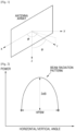
- FIG. 1 illustrates a diagram of a beam radiation direction.
- x, y and z are the three directions of the three-dimensional coordinate system, wherein, r represents beam radiation direction, ⁇ represents horizontal angle of beam maximum radiation direction, and ⁇ represents vertical angle of beam maximum radiation direction.
- HPBW is half-power beam width, and also referred to as the 3dB (decibel) beam width, which is the beam width between two points at which the power is reduced by half (3dB) relative to the beam maximum radiation direction.
- FIG. 2 illustrates a diagram of HPBW of a beam.
- HPBW includes HPBWh and HPBWv
- HPBWh represents horizontal half power beam width, and may be referred to as horizontal dimension width of beam, which is the key indicator reflecting beam width in horizontal direction
- HPBWv represents vertical half power beam width, and may be referred to as vertical dimension width of beam, which is the key indicator reflecting beam width in vertical direction.
- the parameter values ⁇ , ⁇ , HPBWh, HPBWv ⁇ of the beam is decided by phase shifts on antenna elements.
- Beam width refers to the coverage range of beam, which may also be referred to as the beam coverage range. Beam width may be indicated by two components, the beam width in horizontal direction (horizontal dimension) and the beam width in vertical direction (vertical dimension).
- the beam width in the horizontal dimension is the size of horizontal dimension coverage angle, i.e., HPBWh as described above
- the beam width in the vertical dimension is the size of vertical dimension coverage angle, i.e., HPBWv as described above. For example, if the horizontal dimension angle coverage range of one beam is 10° ⁇ 20°, the beam width in the horizontal dimension of the beam is 10°.
- a beam area which is also referred to as a set area in the following description, is the area corresponding to the horizontal dimension angle coverage range and vertical dimension angle coverage range of the beam used by the UE according to the embodiments of the disclosure.
- One cell defined or configured by the base station may include one or more beam areas. The coverage ranges of different beam areas may be the same or different.
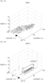
- FIG. 3 illustrates a diagram of a beam area (a set area) of a cell.
- one cell 30 may include a plurality of beam areas.
- the beam area is a minimum area that is controlled according to the embodiment of the disclosure.
- the beam area can be identified with a horizontal and avertical angle range defined by beam.
- the beam area 1 is the coverage range of the beam with the serial number 1 used by the current measurement/report.
- Coverage range information of the beam area refers to information that can determine the horizontal dimension coverage angle range and vertical dimension coverage angle range of the beam area.
- the beam area information may be explicit information, for example, may be a horizontal start angle , an end angle, a vertical start angle and an end angle of the beam area.
- the beam area information includes the horizontal start angle is 0°, the horizontal end angle is 13°, the vertical start angle is 84°, and the vertical end angle is 96°.
- the beam area information may also be indicated implicitly.
- the beam area information may include a horizontal center point angle and a vertical center point angle of the beam area, and a size of horizontal coverage angle (i.e., horizontal dimension width) and a size of vertical coverage angle (i.e., vertical dimension width) instead of the horizontal start angle, the horizontal end angle, the vertical start angle and the vertical end angle of the beam area.
- the beam area information for the beam area 1 may include the horizontal center point angle as 6.5°, the vertical center point angle as 90°, the size of the horizontal coverage angle as 13°, and the size of the vertical coverage angle as 12°.
- a wireless communication system transmits data through a wireless beam.
- Beamforming is a signal processing technique used in antenna arrays for directional signal transmission or reception.
- a beamforming is achieved by a set of antenna arrays.
- Each antenna array consists of several antenna elements and each antenna array can be mapped with one RF Chain. Accordingly, the number of RF Chains or the number of arrays will determine the number of spatial layers that can be supported.
- Each array can generate an analog beam.
- the beam width of each beam may be designed to achieve a target narrow beam gain.
- the number of phase shifters and number of antenna elements will further determine the number of beam directions that can be generated.
- the number of beams direction along with the beamwidth will further determine the total coverage. Implementation can also consider different beambooks. Each beambook will map to different beam patterns.
- Beam patterns can be designed depending on deployment use cases associated with horizontal centric or vertical centric coverages.
- the set of all beams used by a base station for beam measurement and data transmission may be defined as a beambook.
- the number of beams in the beambook is beambook size.
- the beam book may include a relationship between a desired direction and phase shift value for the desired direction.
- the beambook management scheme in the conventional system is to use a fixed beambook for all base stations in the network use.
- the angle distribution of the beam may be uniform or approximately uniform.
- the beambook for the cell may be fixed, and the beambook may not change.
- the coverage angles of the beams in the beambook set are also uniformly or approximately uniformly distributed.
- FIG. 4a illustrates a flowchart of a beam controlling method.
- beambook size, horizontal beam number and vertical beam number of the cell are determined based on beambook size limit information 410 and beam coverage range requirement 420 of the cell.
- the numbers of beams arranged in horizontal direction and in vertical direction of antenna array are determined based on the beambook size limit information 410 and possible beam width supported by the antenna array of the base station.
- the beam coverage range requirement 420 includes the horizontal coverage range and vertical coverage range of the cell, such as the horizontal and vertical angle ranges shown in the FIG. 3 .
- the beam coverage range requirements 420 may be determined according to the network coverage scenario of each operator.
- position (i.e.,, horizontal angle ⁇ and vertical angle ⁇ ) and beam width for each of beams are calculated based on the principle that is to uniformly distribute the beams into the beam coverage range of the cell.
- FIG. 4b illustrates a diagram of a beam distribution of a cell.
- the horizontal dimension coverage angle range corresponding to the beambook is [-120°, 120°]
- the vertical dimension coverage angle range is [-12°, 12°].
- Each of ellipses in FIG. 4b represents a beam
- the size of the ellipse represents coverage range of the corresponding beam
- the coverage angle of each of beams in the beambook is uniformly distributed. As seen from FIG.
- the number of the beams arranged in the horizontal direction is 16 and the number of the beams arranged in the vertical direction is 4, and then the HPBWh of each of beams in the beambook is 240°/16, i.e., 15°, the HPBWv is 24°/4, i.e., 6°, the set of ⁇ of beams is ⁇ 7.5, ⁇ 22.5,... ⁇ , and the set of ⁇ is ⁇ 3°, ⁇ 9° ⁇ .
- the distribution of the beam in the cell is uniform, and the fixed beambook is used.
- a traffic distribution in the cell may not be uniform.
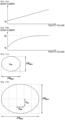
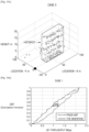
- FIG. 5 illustrates a diagram of coverage effect.
- the largest ellipse area 50 represents the coverage range of the cell (i.e., the base station), and the beams in each beam area of the cell are uniformly distributed.
- the area A1 is a hotspot area, that is, a high load area
- the area A2 is low load area, but the beam densities of the hotspot area A1 and the low load area A2 are the same, which will result in poor coverage and poor user communication in the area A1, and the waste of beam resources in the area A2.
- the beam utilization rate is low.
- Embodiments of the disclosure provide a beam controlling method, apparatus, electronic device, and computer-readable storage medium. According to the embodiment of the disclosure, traffic distribution in a cell is predicted by using historic data of the traffic distribution in the cell, beams for areas with different traffic densities to form a beambook of the cell are adaptively selected according to the predicted traffic distribution.
- the embodiment of the disclosure it is possible to select more and narrower beams for hotspot areas, thereby using a denser and narrower beams to bring coverage gains to hotspot area, and select less and wider beams for low load areas to improve beam utilization efficiency and maintain coverage to ensure communication performance in low load areas.
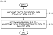
- FIG. 6 illustrates a flowchart of a beam controlling method according to an embodiment.
- the beam controlling method may include the following operations:
- Operation S 110 obtaining traffic distribution data of each set area in a cell.
- Operation S120 determining beams of the cell according to the traffic distribution data of each set area.
- the traffic distribution data of a beam area refers to data indicating traffic distribution situation of each of the beam areas included in the cell, and the data may refer to traffic volume or traffic density.
- the traffic distribution data may be the traffic density of the beam area, and the traffic density may be determined based on the traffic volume and the coverage area of the beam area.
- the traffic density may be traffic volume in one unit area or relative traffic density.
- the traffic density of the beam area may be obtained by dividing the traffic volume of the beam area by the coverage area of the area.
- the traffic density indicates traffic volume per unit area (traffic volume/unit area).
- the traffic density of the beam area may also be obtained by dividing the traffic volume of the beam area by a reference area.
- the reference area may be the coverage area of any beam area in the cell, or portion of any beam area. In this case, the traffic density indicates relative traffic density compared to the reference area.
- the event refers to events that may affect the traffic, such as concerts, competitions, and so on.
- the granularity of the information such as time, date, and weather, etc. may be configured and adjusted.
- the manner of determining the traffic distribution data of each beam area in the cell according to the area-related information of the cell is not limited in the embodiments of the disclosure. For example, statistical analysis may be performed on the historic area-related information of each cell and the historic traffic distribution data of each beam area in the corresponding cell. Then, a mapping relationship between the area-related information and the traffic distribution data is established based on the analysis results. When current traffic distribution data of each of beam areas in the cell is to be determined, the corresponding traffic distribution data may be found from the mapping relationship according to the current area-related information of the cell.
- the sample area-related information may be historic area-related information of the cell, which may include, but is not limited to, the location of the cell and/or historic environment data of the cell, etc. and the sample traffic distribution data may be historic traffic distribution data corresponding to the historic area-related information.
- the sample area-related information for each category may be labeled with a corresponding category label that represents the sample traffic distribution data of each beam area in the cell corresponding to the sample area-related information for the category.
- the labeled sample area-related information is used as the input of the model, and the output of the model is the predicted traffic distribution data.
- An artificial neural network may include, for example, and without limitation, a deep neural network (DNN) and may include, for example, and without limitation, a convolutional neural network (CNN), a DNN, a recurrent neural network (RNN), a restricted Boltzmann machine (RBM), a deep belief network (DBN), a bidirectional recurrent DNN (BRDNN), deep Q-networks (DQN), or the like, but is not limited thereto.
- DNN deep neural network
- CNN convolutional neural network
- RNN recurrent neural network
- RBM restricted Boltzmann machine
- DNN deep belief network
- BDN bidirectional recurrent DNN
- DQN deep Q-networks
- the obtaining the training samples may include: obtaining each initial sample data, one piece of initial sample data including a type of initial area-related information of the cell and initial traffic distribution data of the cell under the initial area-related information, wherein the initial traffic distribution data of one cell includes the traffic distribution data of each beam area in the cell; determining the category of the initial traffic distribution data of the cell in each initial sample data, and obtaining classification results of the initial traffic distribution data; labeling the initial area-related information of the cell corresponding to the initial traffic distribution data with corresponding category label based on the classification results of the initial traffic distribution data, to obtain sample areas-related information; and obtaining sample traffic distribution data corresponding to sample historic area-related information of the same category based on the initial traffic distribution data belonging to the same category.
- Each piece of initial sample data may be historic-related data of the cell, such as historic environment data of the cell, and historic traffic distribution data of each beam area in the corresponding cell, which are obtained by statistics.
- the initial area-related information and the corresponding initial traffic distribution data among the initial sample data may be classified first, and the model is trained based on the classified data.
- a classification algorithm may be used to classify the obtained initial traffic distribution data (traffic distribution data of each beam area in the cell), and classify the initial area-related information corresponding to the initial traffic distribution data based on the classification result of the initial traffic distribution data.
- the initial traffic distribution data of each category after classification may include a plurality of initial traffic distribution data, and the plurality of initial traffic distribution data may correspond to a plurality of initial area-related information, therefore, the plurality of area-related information may correspond to the same classification label, and the sample traffic distribution data corresponding to the sample area-related information of each category may be obtained based on the initial traffic distribution data of the category.
- the sample traffic distribution data corresponding to the category may be obtained through average, weighted average, or other data fusion methods of the initial traffic distribution data of the category, thereby establishing a correspondence relationship between the sample area-related information of each category and the corresponding sample traffic distribution data.
- the classification algorithm may be selected according to algorithms, such as the Pearson correlation coefficient algorithm (also known as the Pearson association classification algorithm).
- the vector corresponding to the initial traffic distribution data of the cell included in one piece of initial sample data may be expressed as [1.5, 1.7, 2.9, 0, 33] and the vector corresponding to the initial traffic distribution data of the cell included in another piece of initial sample data may be expressed as [3, 3, 3, 3, 3], where the number of elements in the vector is the number of beam areas included in the cell, and the value of each of elements is the value used to represent the traffic distribution data of each beam area.
- the sample area-related information with category label may be used as the input of the model to train the model.
- the parameters of the model are updated based on the predicted traffic distribution data of the cell output by the model and the sample traffic distribution data of the corresponding category, and the model is used as the traffic prediction model when satisfying the conditions at the end of training.
- the determining the category of the initial traffic distribution data in each initial sample data includes: determining correlation between the traffic distribution data of the cell corresponding to the traffic parameter in the two pieces of the initial sample data, respectively, for each traffic parameter, with respect to any two pieces of initial sample data; and determining whether the initial traffic distribution data of the cell in the two pieces of the initial sample data is the same category based on the correlation corresponding to traffic parameters in the two pieces of the initial sample data.
- the obtaining the sample traffic distribution data corresponding to the sample historic area-related information of the same category based on the initial traffic distribution data belonging to the same category includes: obtaining the sample traffic distribution data corresponding to the area-related information of the same category based on the initial traffic distribution data of the traffic parameters belonging to the same category.
- the traffic distribution data of one cell may be traffic data capable of representing a plurality of traffic parameters, that is, for each type of initial area-related information, the initial traffic distribution data of the cell may include initial traffic distribution data of the plurality of traffic parameters.
- the initial traffic distribution data corresponding to the plurality of different traffic parameters may be selected as basic data for training model.
- the initial traffic distribution data of the cell corresponding to each type of area-related information (the plurality of traffic distribution data corresponding to the plurality of traffic parameters)
- whether the initial traffic distribution data of the cell corresponding to the two types of area-related information belong to the same category may be determined comprehensively based on the data correlation of the initial traffic distribution data of the cell corresponding to the traffic parameters under the two types of area-related information.
- the initial traffic distribution data of the cell corresponding to the area-related information includes traffic distribution data corresponding to the two types of parameters.
- the correlation between the two pieces of distribution data under each type of traffic parameter may be calculated respectively, and then whether the two pieces of initial traffic distribution data of the cell is the same type may be obtained based on the correlation corresponding to the two types of traffic parameters.
- whether two initial traffic distribution data in the two pieces of initial sample data are the same category may be determined based on the correlation of the traffic distribution data of the cell corresponding to each traffic parameter of the cell in the two pieces of initial sample data and the weight corresponding to each traffic parameter.
- the correlation between the two pieces of traffic distribution data of the cells may be obtained by configuring a weight corresponding to each traffic parameter and performing weighted fusion on the correlation corresponding to each traffic parameter, such that whether the two pieces of traffic distribution data of the cell may be divided into the same category is determined, that is, whether the area-related information respectively corresponding to the two pieces of traffic distribution data of the cell belongs to the same category is determined.
- the method for obtaining the sample traffic distribution data corresponding to the area-related information of the same category based on the initial traffic distribution data of each traffic parameter belonging to the same category is not limited in the embodiment of the disclosure.
- the method may include averaging or performing weighted fusion on the initial traffic distribution data of each traffic parameter of the same category, etc.
- the beams of each beam area in the cell may be flexibly determined based on the traffic distribution data.
- the traffic distribution data of a cell is represented by the plurality of traffic parameters
- the traffic distribution data of each beam area in the cell corresponding to each type of traffic parameter may also be determined, and the beams of the beam area is determined based on the traffic distribution data of each set area corresponding to each traffic parameter.
- new traffic distribution data capable of representing the traffic distribution data of each traffic parameter of the cell may be determined according to predetermined rules based on the determined traffic distribution data of the beam area corresponding to the traffic parameter.
- the new traffic distribution data is obtained by averaging or weighted averaging the traffic distribution data of each traffic parameter, and the beams of the set area may be determined based on the new traffic distribution data.
- the traffic prediction model that is, the corresponding traffic prediction model may be trained and obtained for each type of traffic parameter
- the traffic prediction model corresponding to each traffic parameter or the parameters of the model corresponding to each type of traffic parameter is trained and obtained base on the training samples corresponding to each type of traffic parameter, or traffic distribution data of each set area corresponding to each type of traffic parameter is obtained based on the traffic prediction model or the parameters of the model corresponding to each traffic parameter.
- a beam controlling method may include obtaining traffic distribution data of a plurality of beam areas included in the cell; determining a total number of beams for a beam area among the plurality of the beam areas based on the traffic distribution data; determining a beam width of a beam for the beam area based on the total number of beams; determining candidate beams for the beam area from a candidate beam set based on the total number of beams and the beam width of the beam; and determining beams for the beam area from the candidate beams based on a distance between the candidate beams and the beam area.
- the beam width of each beam area include the beam width in the horizontal dimension (i.e., the horizontal dimension beam width) and the beam width in the vertical dimension (i.e., the vertical dimension beam width) of the set area.
- the number of the beams arranged in the horizontal direction and the number of the beams arranged in the vertical direction for the set area may be determined according to the ratio (may also be simply referred to as vertical and horizontal beam number ratio) information of the beams arranged in the horizontal direction to the beams arranged in the vertical direction, so that the beam width of the set area is further determined according to the individual beam area information of the beam area, that is, the width of the beam in horizontal dimension of the beam area is determined according to the angle coverage range in the horizontal dimension and the number of the beams arranged in the horizontal direction for the beam area, and the width of the beam in the vertical dimension of the area is determined according to the angle coverage range in the vertical dimension and the number of beams arranged in the vertical direction for each beam area.
- the beams of each beam area may be determined from the candidate beams to obtain the beambook of the cell.
- the ratio information of the beams arranged in the horizontal direction and the beams arranged in the vertical direction may be directly the vertical and horizontal beam number ratio, or other information capable of determining the ratio, such as information capable of representing the horizontal beam number and the vertical beam number of the beam area.
- the determining the beams of the beam area from candidate beam set based on the beam width of the beam area includes: determining candidate beams of the beam area from the candidate beam set based on the beam width of the set area; and determining the beams of the beam area from the candidate beams of the beam area based on the distance between the candidate beams and the beam area.
- the candidate beam set refers to all beams in the system, and the beams included in the beambook of each cell are the beams in the set.
- all beams of each beam area may be selected from all candidate beams in the system to generate the beambook of the cell according to the beam width.
- all beams for this beam area may be filtered out according to the beam width of the beams for the beam area and the beam width of the beams in the candidate beam set.
- some candidate beams may be filtered out from the candidate beam set based on the beam widths of the beams, and then the beams of the beam area is filtered out based on the distance of the candidate beams and the beam area.
- the distance from a beam to a beam area refers to a distance from a center of the beam to a center of the beam area.
- the distance from a first beam to a second beam may refer to a distance from a center of the first beam to a center of the second beam.
- the distance from one beam to another beam may be determined based on direction vector of center location of the beam and center point vector of the beam area.
- the candidate beam set includes candidate beam subsets divided according to the beam widths.
- the determining the candidate beams of the beam area from the candidate beam set based on the beam width of the beam area may include: determining the target beam subset corresponding to the beam area from the candidate beam subsets based on the beam width of the beam area and the beam width corresponding to each candidate beam subset, and determining beams in the target beam subset as the candidate beams for the beam area.
- the candidate beam set of the system may include a plurality of beam subsets, and the beam subsets may be divided according to the beam widths, that is, the system supports the plurality of candidate beam subsets with different beam widths.
- one or more target candidate beam subsets for each set areas may be firstly determined according to the beam width of each beam area from candidate beam subsets; and then final beams of each beam area are determined from the determined target candidate beam subsets.
- the candidate beam subset that has the beam width closest to that of the beam area may be used as the target beam candidate subset for the beam area.
- the beam width of the beam subset refers to a width used to represent the beam width of beams included in the subset, and the representing of the beam width of the candidate beam subset is not limited in the embodiment of the disclosure.
- the beam width corresponding to each of subset may be configured, and each of the beams is assigned to a subset of the corresponding width according to the beam widths of the beams and the beam width of the subsets.
- the beam width of each of the subsets may be a pre-configured beam width, or the beam width of the subset may be determined according to the beam widths of all beams included in the subset. For example, the average value of the beam widths of all beams included in the subset is determined as the beam width of the beam subset.
- the determining the beams of the beam area from candidate beam set based on the beam width of the beam area includes: using the beam area and neighboring beam area of the beam area as a united area in case that the total number of beams for the beam area is less than a first threshold value, and determining each beam for the united area from the candidate beam set based on the beam width of the united area.
- the first threshold value may be configured, for example, it may be set to 1.
- a plurality of neighboring beam areas may be combined and processed as an united area.
- the beam width of the united area is determined based on the beam width of each beam area included in the united area.
- the width of the beam selected for the united area may be the largest beam width among the beam widths of the beam areas included in the united area to ensure the coverage effect of each beam area, or may be the beam widths selected for the beam areas included in the united area, that is, the beam width of the united area includes a plurality of beam widths.
- target candidate beam subset corresponding to the united area may be determined from the candidate beam subsets according to the beam width of the united area, and then the beams of the united area are determined from the subset based on the distance between each of the beams in the target candidate beam subset and the united area.
- the neighboring beam area of the beam area may be any one or more beam areas neighboring to the beam area, or may be neighboring beam area determined according to a rule, for example, may be neighboring beam area in which the total number of beams is also less than the first threshold value.
- two neighboring beam areas may refer to the area coverage ranges (which may be in horizontal and/or vertical) of the two neighboring beam areas, or may refer to distance between the two neighboring beam areas (such as the distance between the center point vectors of the two beam areas) satisfies a preset condition, for example, less than a set distance.
- which beam areas belong to the neighboring beam area may be determined according to a preconfigured rule.
- the determining the beams of the united area from the candidate beam set based on the beam width of the united area includes: determining the beam width of the united area based on the beam width of each beam area included in the united area; determining candidate beams of the united area from the candidate beam set based on the beam width of the united area; and determining the beams of the united area from the candidate beams based on the distance between the beams and each beam area included in the united area.
- the beam width of the united area may be determined based on the beam widths of the beam areas included in the united area.
- the beam width of the united area may be the largest beam width among the beam widths of the beam areas included in the united area, or may also be the beam widths of the beam areas included in the united area.
- the determining the candidate beams of the united area from the candidate beam set includes determining the candidate beams from the candidate beam set based on the beam widths of the beam areas included in the united area.
- the beam width of the united area may be the larger one between width A and width B, or may include width A and width B.
- the candidate beams of the united area can be determined similarly to the process of determining the beams of the beam area.
- the candidate beams of the united area are determined, and final beams are selected from the candidate beams based on the distance.
- the distance from one beam to one united area may be determined based on the distance from the beam to each beam area included in the united area.
- the distance may be sum of the distances from the beam to the beam areas included in the united area, that is, a sum distance, may be the maximum value or the minimum value among the distances from the beam to the set areas included in the united area, or may be an average value, and the like.
- the candidate beam set includes a plurality of subsets
- the candidate beams of the united area may be beams in the target candidate beam subset determined according to the beam width of the united area.
- the united area may satisfy any one or any combination of the following conditions: i) the total number of beams for each beam area included in the united area is the same, ii) the beam width for each beam area included in the united area is the same, iii) the total number of beams for each beam area included in the united area is less than a first threshold value, and iv) the sum of the total numbers of beams for all the beam areas included in the united area is less than a second threshold value.
- the beam areas included in the united area may be determined according to any one or any combination of the beam width and the total number of beams for each beam area.
- the beam width of the united area may be directly determined as the beam width of the beam areas included in the united area.
- the second threshold value is not less than the first threshold value, and the second threshold value may be equal to the first threshold value.
- the determining the total number of beams for the beam area according to the traffic distribution data of the beam area including any one or any combination of the following: determining the total number of beams for the beam area according to the traffic distribution data of the beam area, and the mapping relationship between the pre-configured traffic distribution data and the beam number; and determining the total number of beams for the beam area according to the traffic distribution data of the beam area and any one or any combination of the following information: total traffic data distribution of all beam areas in the cell, beambook size of the cell, set value of the minimum beam number of the beam area, and set value of the maximum beam number of the beam area.
- the total number of beams for each beam area may be determined through a pre-configured traffic volume mapping relationship. Different traffic distribution data may be mapped to one beam number, and after determining the traffic distribution data of each beam area, the corresponding beam number may be found through the mapping relationship.
- the beam number refers to the total number of beams for the beam area.
- each beam area may be set with a limit of the minimum beam number, i.e., the above set value of the minimum beam number.
- the ratio of the beams arranged in the horizontal direction and the beams arranged in the vertical direction for each beam area is pre-configured, or, it is determined by any way of the following: determining the ratio of the beams arranged in the horizontal direction and the beams arranged in the vertical direction for each beam area according to the individual coverage range information of each beam area, and determining the ratio of the beams arranged in the horizontal direction and the beams arranged in the vertical direction for each beam area according to the coverage range information of all the beam areas in the cell.
- the ratio of the vertical beam number and the horizontal beam number may be configured by the system or may be determined based on other configuration information.
- the other configuration information may be information that reflects the widths or the width ratio of the vertical and horizontal beams, such as the widths of the vertical and horizontal beams that the antenna system may support, or may be information that reflects the numbers or the vertical and horizontal beam number ratio in the beam area, such as the coverage area information of the beam area.
- the vertical and horizontal beam number ratio of each beam area may be determined according to actual factors. In addition, the vertical and horizontal beam number ratio of for each of the beam areas may be set equally or differently.
- the beams may be adaptively selected for the beam areas according to the traffic densities, and flexible determination of the beambook of a cell may be achieved.
- the traffic distribution data of each beam area it is possible to select more and narrower beams for hotspot areas thereby improving coverage gains of hotspot areas, and select less and wider beams for low load areas thereby improving beam utilization efficiency and ensuring the coverage of low load areas.
- FIG. 7 illustrates a diagram of beam coverage effect according to an embodiment.
- the beam areas i.e., the set areas
- beam areas A1 belong to hotspot area and high load area
- beam areas A2 belong to low load area.
- the number of beams in each beam area in the cell may be determined based on the traffic distribution data of each beam area. As shown in the FIG.
- more and narrower beams may be assigned to each of the beam areas A1 included in the hotspot area, so that the beam areas A1 may obtain better coverage performance, and less and wider beams may be assigned to the beam areas A2 in the low load area thereby improving beam utilization and ensuring the coverage of the low load area.
- the beam area of the cell may be called as the set area.
- FIG. 8a illustrates a flowchart of a beam controlling method according to another embodiment.
- traffic distribution data of a plurality of beam areas included in the cell is obtained.
- a total number of beams for a beam area among the plurality of the beam areas is determined based on the traffic distribution data.
- a beam width of a beam for the beam area is determined based on the total number of beams.
- candidate beams for the beam area from a candidate beam set are determined based on the total number of beams and the beam width of the beam.
- beams for the beam area are determined from the candidate beams based on a distance between the candidate beams and the beam area.
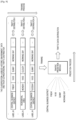
- FIG. 8b illustrates a diagram of a beam controlling method according to an embodiment.
- traffic prediction is performed for the beam areas included in the cell.
- An operation of predicting traffic distribution of the cell may be performed by using AI (that is, a traffic prediction model) based on historic environment data and a historic traffic distribution classification label.
- a traffic prediction model is trained based on the historic environment data and the corresponding traffic distribution data to predict the traffic distribution data of the cell through the model.
- an SVM model may be used as the traffic prediction model.
- Category to which the traffic distribution data of each beam area in the cell belongs may be predicted through the classification model, and the traffic distribution data of the category is the traffic distribution data for the beam area.
- the traffic prediction model may also be a model that directly outputs the traffic distribution data of each beam area. In this example, it is explained through an example in which the traffic prediction model is a classification model and the output of the model is category of traffic distribution data of each beam area.
- training samples may be obtained first.
- the training samples may be obtained through historic environment data (initial area-related information) and corresponding historic traffic distribution data (that is, initial traffic distribution data) of the cell.
- the historic environment data may include, but is not limited to, time, date, weather, events, etc.
- the historic traffic distribution data information includes the traffic volume information of each beam area of the cell under the historic environment data.
- the traffic volume information may be implemented by the parameters (i.e., the traffic parameters) such as the average throughput in the beam area, the number of users accessing or transmitting traffics, and the amount of buffered data (the amount of data to be transmitted), and the traffic volume information may be one of the parameters or a combination of the plurality of parameters.
- a classification algorithm may be used to classify historic traffic distribution data, and label the corresponding historic environment data thereof.
- the Pearson correlation algorithm may be used to obtain classification of historic traffic distribution data through correlation operation between historic traffic distribution data vectors of the cell measured at different times; classify and label the corresponding historic environment data based on the classification result of the historic traffic distribution data; and train the classification model by using the classification-labeled historic environment data as reference samples, that is, training samples.
- traffic distribution data of all beam areas in the cell at a future time point or future period may be predicted by using environment data at the future time point or the future period as the input.
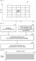
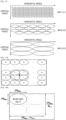
- FIG. 9 illustrates a diagram of a method for predicting traffic distribution data according to an embodiment.
- several types of historic environment data as shown are: ⁇ Central Business District, Friday, 18:30, Sunny, Working Day,... ⁇ , ⁇ Residential Area, Monday, 18:00, Cloudy, Working Day,... ⁇ , ⁇ Central Business District, Tuesday, 18:30, Sunny, Working day,... ⁇
- each type of the historic environment data corresponds to the historic traffic distribution data of each beam area in the cell under the environment data, such as the traffic distribution data corresponding to the environment data ⁇ Central Business District, Friday, 18:30, Sunny, Working Day,... ⁇ is traffic distribution i;
- the historic traffic distribution data is classified by the classification algorithm, and the corresponding historic environment data is labeled, as shown, the traffic distribution i and traffic distribution k are classified into the same category by the classification algorithm, therefore, traffic distribution i and traffic distribution k and their corresponding historic environment data belong to the same label m, and the historic environment data corresponding to traffic distribution j belongs
- the classification model (the traffic prediction module of FIG. 9 ) may be trained based on the classified data.
- the input of the model is historic environment data of each category, and the output is the category of the traffic distribution predicted by the model.
- Whether the training of the model is completed may be judged based on the difference between the traffic distribution data predicted by the model and the sample traffic distribution data, for example, it may be judged by loss function corresponding to the model.
- the value of the loss function represents the difference between the traffic distribution data predicted by the model and the corresponding sample traffic distribution data.
- the environment data of the cell at a time point such as ⁇ Central Business District, Friday, 18:30, Sunny, Working Day ⁇ is input to the trained classification model, and the traffic data distribution of each beam area corresponding to the inputted environment data of the cell is predicted by the model.
- each initial sample data includes a type of historic environment data ⁇ (initial environment data) of a cell and historic traffic distribution data ⁇ (initial traffic distribution data) of the cell under the historic environmental data.
- each traffic distribution data may be represented by a vector of the traffic distribution data. It can be known from the foregoing description that the historic environment data ⁇ may include various environment information that affects the traffic distribution of the cell.
- the historic environment data may be represented by setting different parameters, such as time parameters (such as 1 for daytime and 0 for night), date parameters (such as 1 ⁇ 7 for Monday to Sunday), weather parameters (such as 1 for sunny, 2 for rainy, 3 for cloudy, and 4 for snowy), holiday parameters (such as 1 for yes, 2 for no), and other possible parameters (for example, the emergency event tags such as concerts, football matches etc.).
- time parameters such as 1 for daytime and 0 for night
- date parameters such as 1 ⁇ 7 for Monday to Sunday
- weather parameters such as 1 for sunny, 2 for rainy, 3 for cloudy, and 4 for snowy
- holiday parameters such as 1 for yes, 2 for no
- other possible parameters for example, the emergency event tags such as concerts, football matches etc.
- the historic environment data may be one of the parameters or a combination of more parameters.
- a type of parameters may be further refined, for example, for the rainy, rainfall parameter etc. may be added.
- the historic traffic distribution data ⁇ includes a vector that may represent the traffic distribution situation of each beam area in the cell. It may be represented by traffic parameters such as throughput, the number of connected UEs, and the amount of buffered data etc.
- Sk(t) represents the area covered by the kth beam area at time t
- Sk' is the area covered by a reference beam area (also known as the base beam area), that is, the area of reference area, which is a constant.
- sequence ⁇ T1'(t), T2'(t), T3'(t),...,Tk'(t) ,...,TN'(t) ⁇ represents traffic distribution information of all the beam areas. It can be understood that when the traffic distribution data is represented by a plurality of traffic parameters, Tk'(t) represents the traffic distribution data represented by each traffic parameter of the kth beam area at time t.
- a multidimensional traffic information classification algorithm (for example, based on the Pearson association classification algorithm) may be used to classify the historic traffic distribution data.
- ⁇ represents correlation between two vectorized historic traffic distribution data of the cell (the historic traffic distribution data of all beam areas in the cell, when the plurality of traffic parameters are used, it is the historic traffic distribution data of all beam areas in the cell corresponding to each traffic parameter).
- BT represents the number of the types used as the traffic parameters. For example, if the traffic parameters include throughput, the number of connected UEs, and the buffered traffic, the value of BT is 3.
- PCCi represents correlation factor (correlation) between the two vectorized historic traffic distribution data of the cell (the historic traffic distribution data of all beam areas in the cell) corresponding to the ith type of traffic parameter, and the equation of PCCi may be expressed by the following Equation 4:
- N represents the number of beam areas included in the cell
- ⁇ R,i,j, ⁇ E,i,j respectively represents two historical traffic distribution data corresponding to the ith traffic parameter of the jth beam area in the two cells R and E.
- R and E may be the same cell or different cells.
- the correlation between the traffic distribution data of the two cells corresponding to each traffic parameter may be calculated. Then based on the Equation 3, the correlation between the two historic traffic distribution data may be calculated, where if
- cell A includes 5 beam areas
- cell B also includes 5 beam areas.
- traffic parameter 1 it is assumed that the normalized traffic distribution data of the 5 beam areas in the cell A are a11, a12, a13, a14, a15, respectively, and the normalized traffic distribution data of the 5 beam areas in the cell B are b11, b12, b13, b14, b15, respectively.
- the normalized traffic distribution data of the 5 beam areas in the cell A are a21, a22, a23, a24, a25, respectively
- the normalized traffic distribution data of the 5 beam areas in the cell B are b21, b22, b23, b24, b25, respectively.
- R and E correspond to the cells A and B
- ⁇ R,i,j and ⁇ E,i,j respectively correspond to the traffic distribution data corresponding to the traffic parameter 1 of the jth beam area in the cells A and B.
- ⁇ R,i,j and ⁇ E,i,j correspond to a11 and b11, respectively.
- classifying the historical traffic distribution data in each cell may be completed, and the corresponding historic environment data may be labeled according to the classification result of the traffic distribution data.
- the labeled historic environment data may be used as sample environment data among the training samples.
- sample traffic distribution data corresponding to the type of the environment data may be determined based on all the historic traffic distribution data corresponding to the type of environment data.
- the classification-labeled historic environment data and the corresponding sample traffic distribution data may be used as training samples for subsequent traffic prediction model, and the training of the model is completed based on the training samples.
- the obtained environment data of the cell may be input into the model, and the traffic distribution data of each beam area in the cell under the environment data may be obtained based on the output of the model.
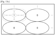
- the beam areas included in a cell include beam area 1, beam area 2, ..., beam area k, beam area k+1, beam area k+2, beam area k+3.
- the traffic distribution data of each beam area in the cell may be obtained based on the trained traffic prediction model.
- the traffic distribution data of beam area k, beam area k+1, beam area k+2, and beam area k+3 may be expressed as Tk, Tk+1, Tk+2, Tk+3, respectively.
- the beam number to cover each beam area in the cell is calculated according to the predicted traffic distribution data of each beam area in the cell.
- the beam number may be determined according to the traffic information (the traffic distribution data of each beam area) and the beambook size limit of the cell.
- the beam number (that is, the total number of beams) to cover each beam area may be calculated according to the predicted traffic volume (that is, traffic distribution data, which may be referred to as the predicted traffic volume) in each beam area and the beambook size of the cell. In actual applications, due to resource limit, the beambook size is limited.
- the calculation method of the beam number for each beam area usually has the following characteristics:
- the following describes several examples for determining the beam number to cover each beam area in the cell based on the predicted traffic distribution data of each beam area in the cell.
- the relationship between the beam number for each of the beam areas and the predicted traffic volume of the beam area may be linear, and the beam number is proportional to the traffic volume.
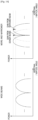
- FIG. 10a illustrates a diagram of a relationship between beam number and traffic distribution data.
- the horizontal axis represents the predicted traffic volume
- the vertical axis represents the beam number selected in the beam area.
- mk is the calculated beam number of the beam area k
- P is the total size of the beambook limit of the cell
- Tk is the predicted traffic volume of the beam area k
- ⁇ n 1 N
- T n is the total traffic volume of all the beam areas included in the cell
- ⁇ k is the minimum beam number in the beam area k.
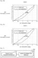
- the relationship between the beam number for each of the beam area and the predicted traffic volume in the beam area is a non-linear relationship, and the beam number is proportional to the traffic volume.
- FIG. 10b illustrates a diagram of a relationship between beam number and traffic distribution data in another example.
- mk is the calculated beam number of the beam area k
- Tk is the predicted traffic volume of the beam area k
- ⁇ k is the set minimum beam number of beam area k.
- ⁇ k is the set maximum beam number of the beam area k, that is, the set value of the maximum beam number of the beam area k.
- the set maximum beam number corresponding to each beam area may be the same or different. It can be known from the foregoing description that the sum of the set values of the maximum beam numbers corresponding to all beam areas in the cell is not greater than the total size of the beambook limit of the cell.
- the beam number for each beam area may be determined by the traffic volume mapping relationship. For example, a range of the traffic volume is mapped to a beam number, the system may pre-store the mapping relationship table between the traffic volume and the beam number. For example, as shown in Table 1, each traffic volume range corresponds to a beam number. For each beam area, after determining the predicted traffic volume of each beam area, the beam number for each beam area may be determined through the mapping relationship. For example, assuming that the predicted traffic volume of a beam area is in a range greater than A1 and not greater than A2, the beam number for the beam area is 1/2.
- the beam numbers for beam areas k, beam area k+1, beam area k+2, and beam area k+3 are 6, 1, 0.5, and 0.5, respectively.
- the beam widths in the horizontal dimension and vertical dimension of each beam area are determined according to the determined beam number and coverage range information of each beam area in the cell.
- the beam widths in the horizontal dimension and vertical dimension of each beam area are determined according to the beam number of each beam area and the coverage range information of each beam area, and other configuration information.
- the input information includes the beam number for each of the N beam areas, coverage range information of each beam area, and other configuration information of each beam area (such as number ratio information of the horizontal dimension and the vertical dimension).
- Hmi (1 ⁇ i ⁇ N) represents the beam width in the horizontal dimension of the ith beam area
- Vmi represents the beam width in the vertical dimension of the ith beam area
- the other configuration information refers to information for determining the ratio of the beams arranged in the horizontal direction and the beams arranged in the vertical direction for each beam area, that is, information that may reflect the beam widths or the beam width ratio of the vertical direction and horizontal direction, or information that may reflect the numbers of the vertical and horizontal beams or the vertical and horizontal beam number ratio in the beam area, such as the vertical and horizontal beam widths supported by the antenna system, or the vertical and horizontal beam number ratio configured by system parameters.
- the ratios of the beam areas in a cell may be the same or different, and the ratios may be pre-configured or may be calculated in real time.
- the ratio may be a preset ratio, or may be selected from a preset ratio set. In a case in which there is only one preset ratio, the horizontal and vertical dimension beam number ratio in all beam areas are the same.
- the beam areas may be the same or different. If the horizontal and vertical dimension beam number ratio in each beam area is set to be the same, the ratios may be determined according to the widths in the horizontal and vertical dimension in the coverage range information of all beam areas.
- the ratios may be determined by the following operations: 1) calculating the sum of the widths in the horizontal dimension of the coverage range information of all beam areas and assuming the sum is Total_BW_h; 2) calculating the sum of the widths in the vertical dimension of the coverage range area information of all beams and assuming the sum is Total_BW_v; and 3) finding a ratio closest to Total_BW_h/Total_BW_v among a candidate ratio set, then the ratio closest to Total_BW_h/Total_BW_v is determined as the horizontal and vertical dimension beam number ratio.
- the ratio of each beam area may be determined according to the widths in the horizontal and vertical dimension in the coverage range information of each beam area.
- the ratio may be determined by the folllowing operations: 1) for each beam area, calculating the ratio of the width BWmk,h in the horizontal dimension to the width BWmk,v in the vertical dimension of the coverage range information of the beam area, i.e.,BWmk,h/BWmk,v; and 2) finding a ratio closest to BWmk,h/BWmk,v among a candidate ratio set, then the ratio closest to BWmk,h/BWmk,v is determined as the horizontal and vertical dimension beam number ratio of the beam area.
- the beam areas may be the same or different. If the horizontal and vertical dimension beam number ratio in each beam area is set to be the same, the ratios may be determined according to the widths in the horizontal and vertical dimension in the coverage range information of all beam areas. For example, the ratios may be determined by the following operations: 1) calculating the sum of the widths in the horizontal dimension of the coverage range information of all beam areas and assuming the sum is Total_BW_h; 2) calculating the sum of the widths in the vertical dimension of the coverage range area information of all beam areas and assuming the sum is Total_BW_v; and 3) then the horizontal and vertical dimension beam number ratio is Total_BW_h/Total_BW_v.
- the ratio of each beam area is determined according to the widths in the horizontal and vertical dimension in the coverage range information of each beam area. That is, the horizontal and vertical dimension beam number ratio of the beam area is BWmk,h/BWmk,v.
- the beam numbers in the horizontal and vertical dimension of each beam area may be calculated based on the other configuration information described above, and then the widths in the horizontal and vertical dimension of the beam area may be calculated according to the calculated beam numbers in the horizontal and vertical dimension, and the beam area coverage range information of the beam area, wherein the beams in each beam area may be distributed uniformly or non-uniformly.
- the horizontal dimension beam width and the vertical dimension beam width may be determined according to the beam number in each beam area, the coverage range information of the beam area, and the configured beam number ratio in the horizontal and vertical dimension of the beam area, respectively. From the foregoing description, it can be known that for the configured beam number ratio in the horizontal and vertical dimension, the beam areas may be the same or different, and the ratio may be a preset ratio or may be selected from a preset ratio set.
- the horizontal dimension beam number and the vertical dimension beam number of each beam area may be calculated according to the beam number in each beam area, and the configured beam number ratio in the horizontal and vertical dimension.
- the product of the horizontal dimension beam number and the vertical dimension beam number is equal to the beam number in the beam area.
- the configured beam number ratio in the horizontal and vertical dimension is X: Y.
- the horizontal dimension beam number and vertical dimension beam number of the beam area k may be determined by the following equations 8 and 9:
- the horizontal dimension beam width and the vertical dimension beam width of the beam area are calculated according to the calculated horizontal and vertical dimension beam numbers and the beam area coverage range information of the beam area, respectively. Assuming the beams of the beam area k are distributed uniformly, and then the horizontal dimension beam width and the vertical dimension beam width of the beam area k may be determined by the following equations 10 and 11:
- BWmk,h and BWmk,v are the horizontal dimension width and the vertical dimension width in the beam area coverage range information of the beam area k, respectively.
- FIG. 11a illustrates a diagram of coverage range information of one beam area.
- the elliptical area represents the coverage range of the beam area k.
- the horizontal dimension width of the beam area k is BWmk,h
- the vertical dimension width is BWmk,v
- mk represents the beam number for the area. Assuming that the number of the beams arranged in the horizontal direction, i.e., the horizontal dimension beam number is mk_h , and the vertical dimension beam number is mk_v.
- FIG. 11b illustrates a diagram of horizontal dimension beam width and vertical dimension beam width of the beam area as shown in FIG. 11a.
- FIG. 11b is an enlarged diagram of the beam area in FIG. 11a .
- the horizontal dimension beam width and the vertical dimension beam width of each beam area may be determined according to the beam number in each beam area, the coverage range information of the beam area, and the beam number ratio in the horizontal and vertical dimension calculated in real time, respectively.
- the beam number ratio in the horizontal and vertical dimension may be calculated in real time.
- the horizontal dimension beam number and the vertical dimension beam number of each beam area may be calculated according to the beam number in each beam area, and the beam number ratio in the horizontal and vertical dimension in each beam area calculated in real time.
- the product of the horizontal dimension beam number and the vertical dimension beam number is equal to the beam number in the beam area.
- the horizontal dimension beam number and vertical dimension beam number of the beam area k may be determined by the following equations 12 and 13:
- the horizontal dimension beam width and the vertical dimension beam width of the beam area are calculated according to the calculated horizontal and vertical dimension beam numbers and the beam area coverage range information of the beam area k, respectively. Assuming the beams of the beam area k are distributed uniformly, and then the horizontal dimension beam width and the vertical dimension beam width of the beam area k may be determined by the following equation 14 and 15:
- BWmk,h and BWmk,v are the horizontal dimension width and the vertical dimension width in the beam area coverage range information of the beam area k, respectively.
- the horizontal dimension beam width and the vertical dimension beam width of each beam area may be determined according to the beam number in each beam area, the coverage range information of the beam area, and the configured beam number ratio in the horizontal and vertical dimension, respectively.
- the horizontal dimension beam number and the vertical dimension beam number of each beam area may be calculated according to the beam number in each beam area, and the configured beam number ratio in the horizontal and vertical dimension.
- the sum of the horizontal dimension beam number and the vertical dimension beam number is equal to the beam number in the beam area.
- the horizontal dimension beam number and the vertical dimension beam number of the beam area k may be determined by the following equations 16 and 17:
- the horizontal dimension beam width and the vertical dimension beam width are calculated according to the calculated horizontal and vertical dimension beam numbers and the coverage range information of the beam area, respectively. Assuming the beams of the beam area k are distributed uniformly, and then the horizontal dimension beam width and the vertical dimension beam width of the beam area k may be determined by the following equation 18 and 19:
- BWmk,h and BWmk,v are the horizontal dimension width and the vertical dimension width in the beam area coverage range information of the beam area k, respectively.
- the horizontal dimension beam width and the vertical dimension beam width of each beam area may be determined according to the beam number in each beam area, the coverage range information of the beam area, and the beam number ratio in the horizontal and vertical dimension calculated in real time, respectively.
- the horizontal dimension beam number and the vertical dimension beam number of each beam area may be calculated according to the beam number in each beam area, and the beam number ratio in the horizontal and vertical dimension calculated in real time.
- the product of the horizontal dimension beam number and the vertical dimension beam number is equal to the beam number in the beam area.
- the horizontal dimension beam number and the vertical dimension beam number of the beam area k may be determined by the following equations 20 and 21:
- the horizontal dimension beam width and the vertical dimension beam width are calculated according to the calculated horizontal and vertical dimension beam numbers and the coverage range information of the beam area, respectively. Assuming the beams of the beam area k are distributed uniformly, and then the horizontal dimension beam width and the vertical dimension beam width of the beam area k may be determined by the following equations 22 and 23:
- BWmk,h and BWmk,v are the horizontal dimension width and the vertical dimension width in the beam area coverage range information of the beam area k, respectively.
- the beam numbers for the beam area k and the beam area k+1 is 6 and 1, respectively, both of which are not less than 1.
- the horizontal dimension beam width and the vertical dimension beam width of the two beam areas may be determined based on the beam number for each of the two beam areas and the coverage range information of the beam areas. As shown in the FIG. 8b , the horizontal dimension beam width and the vertical dimension beam width of the beam area k are represented as Hmk and Vmk, the horizontal dimension beam width and the vertical beam width of the beam area k+1 are represented as Hmk+1 and Vmk+1.
- the beam numbers for both of the beam areas are 0.5, and the two areas may be used as an united area.
- the horizontal dimension beam width and the vertical dimension beam width of the united area are Hmk23 and Vmk23, the two beam areas may share the same beam.
- all beams of all beam areas from the system candidate beam set or candidate beam subsets is determined to generate a beambook of the cell, based on the determined beam number and beam width of each beam area in the cell.
- the generated beambook is applied.
- the determination method may be different for different system configurations. If all candidate beams configured by the system are included in a set (that is, a candidate beam set), all beams of each beam area may be determined from the set according to the determined beam number and beam width of each beam area, and the beam width of the candidate beam. If all candidate beams configured by the system are included in the plurality of candidate beam subsets each of which has different beam width, the corresponding subset may be selected from the plurality of candidate beam subsets according to the beam width of each beam area and the beam width of each of the subsets, and then the corresponding number of beams may be selected from the selected subset.
- FIG. 12 illustrates a diagram of candidate beam subsets of different beam widths.
- Candidate beam subsets with different beam widths may be supported by the system.
- candidate beam subsets may include three different types of beam widths that represent as W(H1, V1), W(H2, V2), W(H3, V3), respectively.
- Each ellipse in the FIG. 12 represents the horizontal dimension beam width and the vertical dimension beam width of a beam.
- the horizontal dimension beam width (that is, the horizontal angle) of the subset W(H1, V1) is H1
- the vertical dimension beam width (that is, the vertical angle) thereof is V1
- the horizontal dimension beam width of the subset W(H2, V2) is H2
- the vertical dimension beam width thereof is V2
- the horizontal dimension beam width of the subset W(H3, V3) is H3
- the vertical dimension beam width thereof is V3.
- a minimum distance criterion wherein the distance refers to the distance from a center of the selected beam to the center of the beam area, is used to select beams for each beam area from the beam set (candidate beam set) supported by the system or subsets of the beam subsets (candidate beam subsets), and all selected beams form the final beambook.
- the beams may be selected from the beam set supported by the system according to a criteria according to the determined beam width of the beam area.
- the method may be called beambook determination method I.
- the beam area and neighboring areas each having the beam number less than 1 may be combined to an united area.
- Beams for the united area may be uniformly selected, that is, a criterion is used to select the number of beams for the united area from the beam set.
- the method may be called beambook determination method II.
- the minimum distance criterion is used as the criterion for determining the beambook of each beam area, where the distance in the minimum distance criterion refers to the distance from the selected beam to the beam area.
- the description is given through an example in which a plurality of beam areas shares one beam.
- the system supports a plurality of candidate beam subsets with different beam widths.
- corresponding beam subset that is, the candidate beam subset
- the number of beams may be selected from the determined subset, and all the selected beams form the final beambook.
- the beambook determination method I For the beam area with a beam number greater than or equal to 1, the beambook determination method I is adopted. That is, the corresponding beam subset is determined according to the calculated beam width of the beam area, and then the number of beams is selected from the beam subset according to the minimum distance criterion.
- the beambook determination method II for the beam area with a beam number less than 1, the beambook determination method II, not covered by the claimed invention, is adopted. That is, the beam area and neighboring areas each having the same beam number may be combined to an united area, and beams for the united area may be uniformly selected. Because the number of the beams for each beam area in the united area is the same, and the corresponding beam width is also the same, the number of the beams is selected from the beam subset with the corresponding width by using the minimum sum distance criterion.
- wn is a direction vector of the nth beam in the beam subset W(Hmk, Vmk) of which the beam width is (Hmk, Vmk)
- uk' represents the conjugate transpose of uk
- abs(uk'* wn) represents the absolute value of the dot product operation result of uk'* wn
- dn represents the distance between the nth beam of the beam subset and the beam area k.
- FIG. 13a illustrates a diagram of a beam subset W(Hmk, Vmk).
- the beam subset is determined according to the horizontal dimension beam width and the vertical dimension beam width of the beam area, i.e., (Hmk, Vmk).
- the set composed of beams in the circle surrounded by the dotted line is a beam subset, where "0" indicates a corresponding unselected beam, and " 1" indicates a corresponding selected beam from the candidate beam subset.
- all the calculated beam distances may be sorted, and mk beams (the number of beams for the beam area k) with smallest distances may be selected and stored in the beambook of the cell.
- the sum distances between all beams in the beam subset and the center points of the beam areas may be calculated based on the dot product method. Finally, a beam corresponding to a smallest beam distance is selected and stored in the beambook.
- Wn is a direction vector of the nth beam in the beam subset W(Hmk, Vmk) of which the beam width is (Hmk, Vmk)
- uks is a center point direction vector of the sth beam area in the united beam area
- a beam corresponding to a smallest beam distance may be selected as the beam of the united area, and stored into the beambook of the cell.
- FIG. 13b illustrates a diagram of beam areas included in an united beam area.
- the united area includes four beam areas of which the number of beams is less than 1 (mk ⁇ 1 as shown).
- the four beam areas may require the same number of beams, and the horizontal and vertical dimension widths of the coverage range of the four beam areas are also the same.
- the horizontal dimension width and vertical dimension width of the beam area k are BWmk,h and BWmk,v, respectively, and the beam number in the horizontal and vertical dimension are mk_h and mk_v, respectively, then the horizontal dimension beam width and the vertical dimension beam width of the united area are BWmk,h / mk_h and BWmk,v / mk_v, and then candidate beams for the united beam area may be filtered out from the candidate beam set based on the widths, and the beams of the united area may be determined from the candidate beams based on the above-mentioned minimum distance principle.
- FIG. 13c illustrates a diagram of beams of the united area as shown in FIG. 13b .
- a beam corresponding to "1" is a beam of the united area selected from the candidate beam set, and a beam corresponding to "0" represents an unselected beam, and the four dashed ellipses represents the four beam areas included in the united area.
- the united area includes the beam area and the neighboring beam areas each having the beam number less than 1, beams for the united area are uniformly selected. Because the number of beams for each beam area in the united area may be different, a beam number may be selected from the beam subset with corresponding width by adopting minimum sum distance principle.
- the beambook is determined as following operations: Assuming the calculated beam width of the beam area k is (Hmk, Vmk), and a united area includes K beam areas, and then, firstly, the united beam area that is composed of the beam area k and neighboring beam areas each having the beam number less than 1 may be determined. The sum of beam numbers in the united area is less than or equal to 1.
- Wn is a direction vector of the nth beam in one or more beam subsets corresponding to all beam widths in the united beam area
- uks is a center point direction vector of the sth beam area in the united beam area
- a beam corresponding to a smallest beam distance is selected and stored in the beambook.
- the beam for each beam area is selected from beam set supported by the system, and all the selected beams form the final beambook.
- the beambook determination method I is adopted, that is, the beam number is selected from the beam set supported by the system according to the minimum distance criterion.
- the beambook determination method II for beam area with beam number less than 1, is adopted, that is, the beam area and neighboring beam areas that have the same beam number are combined into a united area, and beams for the united area are uniformly selected.
- the beam number is selected from the beam set supported by the system by adopting the minimum sum distance criterion.
- Wn is a direction vector of the nth beam in the beam set W supported by the system, and u'k represents the conjugate transpose of uk .
- Wn is a direction vector of the nth beam in the beam set w supported by the system
- uks is a center point direction vector of the sth beam area in the united beam area
- example 3 The difference between example 3 and Example 4 is that another implementation of the beambook determination method II is provided in this example 3.
- the united area includes the beam area and neighboring beam areas that have the beam number less than 1, the sum of beam numbers in the united area is not greater than 1, and beams for the united area are uniformly selected. Because the beam number of each beam area in the united area may be different, the beam number is selected from the beam subset with corresponding width by adopting the minimum sum distance criterion.
- Wn is a direction vector of the nth beam in the beam set w supported by the system
- uks is a center point direction vector of the sth beam area in the united beam area
- the data transmission service may be provided for the users in the cell based on the determined beam.
- the hotspot area i.e., the beam area k
- the determined 6 narrow beams are used to provide service for the beam area to improve the coverage of the area.
- the medium load area i.e., the beam area k+1
- a relatively wide beam may be used to provide service.
- the low load area i.e., the beam area k+1 and beam area k+2
- a wider beam may be used to provide services for the two beam areas, to achieve the solution for adaptively determining the beambook according to the traffic distribution.
- the beam width and the corresponding number in the beambook may be adjusted in real time according to changes in the traffic; for low traffic areas, less and wider beam may be used to cover to ensure system performance and coverage; and for hotspot areas, more and narrower beams are assigned to improve system performance and user experience, and improve the beam utilization rate.
- the shape of the beam may be regarded as Sine function, denser and narrower beam distribution may bring higher reception signal power gain, so the denser and narrower beam distribution may effectively improve signal power and system capacity in a hotspot area.
- FIG. 14 illustrates a diagram of signal reception power of a wide beam and a narrow beam.
- the horizontal axis represents the beam width (the horizontal/vertical angle), and the vertical axis represents the reception power of the beam.
- the signal reception power of the narrow beam is relatively higher and the performance is better, comparing with the wide beam.
- the gain of the narrow beam is the reception gain corresponding to the wide beam, while the wide beam has a larger coverage range capable of ensuring comprehensive coverage of the low load areas.
- the following table 2 shows the comparison results between the conventional beam management scheme and the adaptive beambook management scheme according to an embodiment of the disclosure. It can be seen from the table, in the coventional beam management scheme, the beams in the beambook of the cell are fixed and the coverage enhancement cannot be provided for various traffic distribution in the cell, and while the adaptive beambook management scheme based on the embodiment of the disclosure may adaptively assign beams according to the traffic distribution of the cell, which can better satisfy the actual application requirements.
- Conventional beambook management scheme Adaptive beambook management scheme Feature Issue Feature Effect Beams in beambook are fixed. Low beam utilization rate, and coverage enhancement cannot be provided for various traffic distribution in the cell. Adaptively assigning beams in the beambook according to predicted traffic distribution. Improvement on signal power gain and system capacity in hotspot area.
- FIGS. 15a, 15b and 15c illustrate diagrams of three different application scenarios in simulations of the disclosure, respectively.
- diagrams of three different application scenarios in the simulations of the disclosure are shown in FIG. 15a, FIG 15b , and FIG 15c , respectively.
- the center point location of the cell is shown by the black dot on the Y axis, that is, the location of "•".
- the coverage area of the three cells may be understood as a hexagon in which the center point location is taken as the circle center and the radius is 100 meters.
- FIG. 15a, FIG. 15b , and FIG. 15c show schematic diagrams of a cell in which each of the distances from all user coordinate points to the center point location is not beyond 100m (only one cell is shown in each of the figures, which is a part of one third of the hexagon).
- the scenarios are as follows:
- the beambook size is 64, that is, the beambook size limit is 64. In other words, the maximum number of beams supported by the system is 64.
- the conventional beam management scheme and the beam determination scheme provided in the embodiments of the disclosure are used to generate the beambook of the cell, respectively, and based on the generated beambook, CDF (Cumulative Distribution Function) simulation of user throughput (that is, UE throughout) is performed on the microcells in the three scenarios.
- CDF Cumulative Distribution Function
- FIGS. 16a , 16b and 16c illustrate graphs of user throughput cumulative distribution function of the three different application scenarios in the simulations of the disclosure, respectively, as shown in FIGS. 15a, 15b and 15c .
- FIG. 16a shows the simulation result in the scenario 1, in which the dashed line represents the simulation result of the prior art, the solid line represents the simulation result of the embodiment of the disclosure, the horizontal axis represents user throughput (Mbps, million bits per second), and the vertical axis represents the CDF value.
- the greater the user throughput the better the performance.
- the user throughput based on the scheme of the embodiment of the disclosure has been greatly improved, and better the beam coverage gains, comparing with the prior art.
- the following table 4 shows the cell performance comparison results in the scenario 1 between the existing scheme and the scheme of the disclosure: [Table 4] Scenario 1 Cell performance Throughput, Mbps Gain Cell average throughput 5% edge user throughput Cell average throughput 5% edge user throughput prior art 166.53 0.14 NA NA disclosure 216.06 0.36 29.7% 157.1%
- the scheme of the embodiment of the disclosure may be used to select a suitable beam for a coverage area, thereby getting about 30% cell average performance improvement.
- these beams with relatively large vertical angle basically have no traffic.
- more beams may be distributed in smaller vertical angle area, or more beams may be distributed in the horizontal dimension, and less and wider beams are used to cover areas with higher vertical angle area, thereby improving beam utilization rate and system performance.
- FIG. 16b shows the schematic diagram of the simulation result in the scenario 2.
- the dashed line represents the simulation result of the prior art
- the solid line represents the simulation result of the embodiment of the disclosure.
- FIG. 16c shows the schematic diagram of the simulation result in the scenario 3.
- the dashed line represents the simulation result of the prior art
- the solid line represents the simulation result of the embodiment of the disclosure.
- an embodiment of the disclosure further provides a beam controlling apparatus.
- FIG. 17 illustrates a structural diagram of a beam controlling apparatus according to an embodiment.
- a beam controlling apparatus 1700 includes a traffic data acquisition module 1710 and a beam determination module 1720.
- the traffic data acquisition module 1710 is configured to obtain traffic distribution data of each beam area in a cell.
- the beam determination module 1720 is configured to determine beams of the cell according to the traffic distribution data of each beam area.
- the beam controlling apparatus 1700 may be a device disposed on the side of base station.
- the apparatus may be a part of the base station, or may be an independent beam management apparatus communicating with the base station.
- the beam determination module 1720 is configured to: determine the total number of beams for each beam area according to the traffic distribution data of each beam area; determine beam width of each beam area according to the total number of beams of each beam area; and determine beams of each beam area from candidate beam set based on the beam width of each beam area.
- the beam determination module 1720 is configured to: determine a number of beams arranged in the horizontal direction and a number of beams arranged in the vertical direction for the beam area according to the total number of beams for the beam area and ratio information of the beams arranged in the horizontal direction and the beams arranged in the vertical direction for the beam area; and determine the beam width of the beam area according to coverage range information of the beam area and the number of the beams arranged in the horizontal direction and the number of the beams arranged in the vertical direction for the beam area.
- the beam determination module 1720 is configured to: determine candidate beams of the beam area from the candidate beam set based on the beam width of the beam area; and determine the beams of the beam area from the candidate beams of the beam area based on the distance between the candidate beams and the beam area.
- the candidate beam set includes candidate beam subsets divided according to the beam widths; accordingly, when determining the candidate beams of the beam area from the candidate beam set based on the beam width of the beam area, the beam determination module 1720 may be configured to: determine the target beam subset of the beam area from the candidate beam subsets based on the beam width of the beam area and the beam width corresponding to each candidate beam subset, and take beams in the target beam subset as the candidate beams of the beam area.
- the beam determination module 1720 may be configured to: use the beam area and neighboring beam area of the beam area as an united area if the total number of beams for the beam area is less than a first threshold value, and determine each beam of the united area from the candidate beam set based on the beam width of the united area.
- the beam determination module 1720 may be configured to: determine the beam width of the united area based on the beam width of each beam area included in the united area; determine candidate beams of the united area from the candidate beam set based on the beam width of the united area; and determine the beams of the united area from the candidate beams based on the distance between the candidate beams and each beam area included in the united area.
- the united area may satisfy any one or any combination of the following: the total number of beams for each beam area included in the united area is the same; the beam width of each beam area included in the united area is the same; the total number of beams for each beam area included in the united area is less than a first threshold value; and the sum of the total numbers of beams for all the beam areas included in the united area is less than a second threshold value.
- the traffic data acquisition module 1710 may be configured to: obtain area-related information of the cell; and determine the traffic distribution data of each beam area in the cell according to the area-related information of the cell.
- the area-related information includes environment data and/or location information of the cell.
- the traffic data acquisition module 1710 may be configured to: predict the traffic distribution data of each beam area through a traffic prediction model according to the area-related information of the cell.
- the above traffic prediction model may be trained by a model training module through the following ways: obtaining training samples, where the training samples include sample area-related information for various categories of cells and sample traffic distribution data of each beam area in the cell corresponding to the sample area-related information for each category; and training an initial prediction model based on the sample area-related information for the various categories until the predicted traffic distribution data for each category output by the initial prediction model and the sample traffic distribution data corresponding to the category satisfy preset condition, and taking the prediction model at the end of the training as the traffic prediction model.
- the model training module may be configured to: obtain each initial sample data, one piece of initial sample data includes a type of initial area-related information of the cell and initial traffic distribution data of the cell under the initial area-related information, wherein the initial traffic distribution data of one cell includes the traffic distribution data of each beam area in the cell; determine the category of the initial traffic distribution data of the cell in each initial sample data, and obtain classification results of the initial traffic distribution data; label the initial area-related information of the cell corresponding to the initial traffic distribution data with corresponding category label based on the classification results of the initial traffic distribution data, to obtain sample areas-related information; and obtain sample traffic distribution data corresponding to sample historic area-related information of the same category based on the initial traffic distribution data belonging to the same category.
- the model training module may be configured to: determine correlation between the traffic distribution data of the cell corresponding to the traffic parameter in the two pieces of the initial sample data, respectively, for each traffic parameter, with respect to any two pieces of initial sample data; and determine whether the initial traffic distribution data of the cell in the two pieces of the initial sample data is the same category based on the correlation corresponding to traffic parameters in the two pieces of the initial sample data.
- the model training module may be configured to: obtain the sample traffic distribution data corresponding to the area-related information of the same category based on the initial traffic distribution data of the traffic parameters belonging to the same category.
- the beam determination module 120 may be configured to perform any one or any combination of the following: determining the total number of beams for the beam area according to the traffic distribution data of the beam area, and the mapping relationship between the pre-configured traffic distribution data and the beam number; and determining the total number of beams for the beam area according to the traffic distribution data of the beam area and any one or any combination of the following information: total traffic data distribution of all beam areas in the cell, beambook size of the cell, set value of the minimum beam number of the beam area, and set value of the maximum beam number of the beam area.
- the ratio information of the beams arranged in the horizontal direction and the beams arranged in the vertical direction for each set area is pre-configured; or, it is determined by any way of the following: determining the ratio information of the beams arranged in the horizontal direction and the beams arranged in the vertical direction for each beam area according to the individual coverage range information of each beam area; and determining the ratio information of the beams arranged in the horizontal direction and the beams arranged in the vertical direction for each beam area according to the coverage range information of all the beam areas in the cell.
- an embodiment of the disclosure further provides an electronic device including a processor and a memory.
- the memory is configured to store a computer program; and the processor is configured to execute the method provided in any embodiment of the disclosure when the computer program is executed.
- An embodiment of the disclosure further provides a computer-readable storage medium.
- the storage medium stores a computer program that, when executed by a processor, the method provided in any of embodiments of the disclosure is implemented.
- FIG. 18 illustrates a diagram of an electronic device according to an embodiment.
- an electronic device 4000 may include a processor 4001 and a memory 4003.
- the processor 4001 and the memory 4003 are connected, for example, through a bus 4002.
- the electronic device 4000 may further include a transceiver 4004. It may be noted that, the transceiver 4004 is not limited to one, and the structure of the electronic device 4000 does not limit the embodiments of the disclosure.
- the processor 4001 may be a CPU (central processing unit), a general-purpose processor, a DSP (Digital Signal Processor), an ASIC (Application Specific Integrated Circuit), or an FPGA (Field Programmable Gate Array) or other programmable logic devices, transistor logic devices, hardware components or any combination thereof. It may implement or perform various logical blocks, modules, and circuits described in connection with the disclosure of the disclosure.
- the processor 4001 may also be a combination that realizes computing functions, for example, a combination including one or more microprocessors, a combination of DSP and microprocessor, and the like.
- the bus 4002 may include a path for transmitting information between the above components.
- the bus 4002 may be a PCI (Peripheral Component Interconnect) bus or an EISA (Extended Industry Standard Architecture) bus, or the like.
- the bus 4002 may be divided into address bus, data bus, control bus, and the like. For ease of representation, only a thick line is used in FIG. 18 , but it does not mean that there is only one bus or one type of bus.
- the memory 4003 may be ROM (Read Only Memory) or other type of static storage device that may store static information and instructions, RAM (Random Access Memory) or other type of dynamic storage device that may store information and instructions, or EEPROM (Electrically Erasable Programmable Read Only Memory), CD-ROM (Compact Disc Read Only Memory) or other optical disk storage, optical disc storage (including compact discs, laser discs, optical discs, digital versatile discs, blue-ray discs, etc.), magnetic disk storage media or other magnetic storage devices, or any other media that may be used to carry or store desired program code in the form of instructions or data structures and may be accessed by a computer, but not limited to thereto.
- ROM Read Only Memory
- RAM Random Access Memory
- EEPROM Electrically Erasable Programmable Read Only Memory
- CD-ROM Compact Disc Read Only Memory
- optical disc storage including compact discs, laser discs, optical discs, digital versatile discs, blue-ray discs, etc.
- magnetic disk storage media or other magnetic storage devices or any other media
- the memory 4003 is configured to store application program code for performing the solutions of the disclosure under the control of the processor 4001.
- the processor 4001 is configured to execute application program code stored in the memory 4003 to implement the solution shown in any one of the foregoing method embodiments.
- steps in the flowchart of the drawings are sequentially displayed in accordance with the directions of the arrows, these steps are not necessarily performed in the order indicated by the arrows. Unless explicitly stated herein, the performing of these steps is not strictly limited, and they may be performed in other orders. Moreover, at least part of the steps in the flowchart of the drawing may include a plurality of sub-steps or a plurality of stages. These sub-steps or stages are not necessarily performed at the same time, but may be performed at different times, and the order thereof is not necessarily performed sequentially either, but may be performed in turn or alternately with other steps or at least part of the sub-steps or stages of other steps.
Landscapes
- Engineering & Computer Science (AREA)
- Computer Networks & Wireless Communication (AREA)
- Signal Processing (AREA)
- Mobile Radio Communication Systems (AREA)
Claims (13)
- Verfahren zum Steuern eines Strahls in einer Zelle, wobei das Verfahren Folgendes umfasst:Erhalten (S810) von Verkehrsverteilungsdaten einer Vielzahl von Strahlbereichen, die in der Zelle enthalten sind;Erhalten (S820) einer Gesamtzahl einer Vielzahl von Strahlen für einen Strahlbereich aus der Vielzahl der Strahlbereiche basierend auf den erhaltenen Verkehrsverteilungsdaten;Erhalten (S830) einer Strahlbreite von einem aus der Vielzahl von Strahlen für den Strahlbereich basierend auf der erhaltenen Gesamtzahl der Vielzahl von Strahlen;Erhalten (S840) von Kandidatenstrahlen für den Strahlbereich aus einem Kandidatenstrahlsatz basierend auf der erhaltenen Gesamtzahl der Vielzahl von Strahlen und der erhaltenen Strahlbreite des einen aus der Vielzahl von Strahlen; undErhalten (S850) mehrerer Strahlen für den Strahlbereich aus den erhaltenen Kandidatenstrahlen basierend auf einem Abstand zwischen einem Zentrum jedes der erhaltenen Kandidatenstrahlen und einem Zentrum des Strahlbereichs durch Auswählen der Strahlen gemäß einem Mindestabstandskriterium.
- Verfahren nach Anspruch 1, wobei das Erhalten der Strahlbreite des einen aus der Vielzahl von Strahlen Folgendes umfasst:Erhalten einer Anzahl von Strahlen, die in horizontaler Richtung angeordnet sind, und einer Anzahl von Strahlen, die in vertikaler Richtung angeordnet sind, für den Strahlbereich basierend auf der erhaltenen Gesamtzahl der Vielzahl von Strahlen für den Strahlbereich, Abdeckungsbereichsinformationen des Strahlbereichs und einer Größe des einen aus der Vielzahl von Strahlen; undErhalten der Strahlbreite des einen aus der Vielzahl von Strahlen basierend auf den Abdeckungsbereichsinformationen des Strahlbereichs und der erhaltenen Anzahl von in horizontaler Richtung angeordneten Strahlen für den Strahlbereich und der erhaltenen Anzahl von in vertikaler Richtung angeordneten Strahlen für den Strahlbereich.
- Verfahren nach Anspruch 2, wobei das Erhalten der Strahlbreite des einen aus der Vielzahl von Strahlen ferner Folgendes umfasst:Erhalten einer horizontalen Strahlbreite durch Dividieren einer horizontalen Strahlbereichsbreite, die in den Abdeckungsbereichsinformationen des Strahlbereichs enthalten ist, durch die erhaltene Anzahl von in horizontaler Richtung angeordneten Strahlen für den Strahlbereich; undErhalten einer vertikalen Strahlbreite durch Dividieren einer vertikalen Strahlbereichsbreite, die in den Abdeckungsbereichsinformationen des Strahlbereichs enthalten ist, durch die erhaltene Anzahl von in vertikaler Richtung angeordneten Strahlen für den Strahlbereich.
- Verfahren nach Anspruch 1, wobei der Kandidatenstrahlsatz eine Vielzahl von Kandidatenstrahlteilsätzen mit verschiedenen Strahlbreiten umfasst, und
wobei das Erhalten der Kandidatenstrahlen für den Strahlbereich Folgendes umfasst:Erhalten eines Zielstrahlteilsatzes für den Strahlbereich aus der Vielzahl von Kandidatenstrahlteilsätzen durch Auswählen eines Kandidatenstrahlteilsatzes mit derselben Strahlbreite wie die erhaltene Strahlbreite des einen aus der Vielzahl von Strahlen; undErhalten der Kandidatenstrahlen für den Strahlbereich aus dem erhaltenen Zielstrahlteilsatz. - Verfahren nach Anspruch 1, wobei das Erhalten der Kandidatenstrahlen für den Strahlbereich Folgendes umfasst:basierend darauf, dass die erhaltene Gesamtzahl der Vielzahl von Strahlen für den Strahlbereich kleiner als eins ist, Kombinieren des Strahlbereichs mit dem einen oder den mehreren benachbarten Strahlbereichen, um den vereinigten Strahlbereich zu erhalten; undErhalten von Kandidatenstrahlen für den erhaltenen vereinigten Strahlbereich aus dem Kandidatenstrahlsatz basierend auf einer Strahlbreite des erhaltenen vereinigten Strahlbereichs.
- Verfahren nach Anspruch 5, wobei das Erhalten der Kandidatenstrahlen für den erhaltenen vereinigten Strahlbereich das Erhalten eines Kandidatenstrahlteilsatzes mit derselben Strahlbreite wie die Strahlbreite des erhaltenen vereinigten Strahlbereichs als Kandidatenstrahlen aus dem erhaltenen vereinigten Strahlbereich umfasst.
- Verfahren nach Anspruch 1, wobei das Erhalten der Verkehrsverteilungsdaten Folgendes umfasst:Erhalten von bereichsbezogenen Informationen der Zelle; undErhalten der Verkehrsverteilungsdaten der Vielzahl von Strahlbereichen, die in der Zelle enthalten sind, basierend auf den erhaltenen bereichsbezogenen Informationen der Zelle.
- Verfahren nach Anspruch 7, wobei das Erhalten der Verkehrsverteilungsdaten ferner das Vorhersagen der Verkehrsverteilungsdaten der Vielzahl von Strahlbereichen, die in der Zelle enthalten sind, durch ein Verkehrsvorhersagemodell umfasst, basierend auf den erhaltenen bereichsbezogenen Informationen der Zelle.
- Verfahren nach Anspruch 8, wobei das Verkehrsvorhersagemodell durch Folgendes geschult wird:Erhalten von Schulungsproben, die eine Probe bereichsbezogener Informationen für eine Vielzahl von Zellenkategorien und eine Probe von Verkehrsverteilungsdaten für jede der Vielzahl von Strahlbereichen in der Zelle umfassen, die der Probe bereichsbezogener Informationen für jede der Vielzahl von Kategorien entspricht; undSchulen eines anfänglichen Vorhersagemodells basierend auf der Probe bereichsbezogener Informationen für die Vielzahl von Kategorien, bis die vorhergesagten Verkehrsverteilungsdaten für jede der Vielzahl von Kategorien, die von dem anfänglichen Vorhersagemodell ausgegeben werden, und die Probe von Verkehrsverteilungsdaten, die einer jeweiligen der Vielzahl von Kategorien entsprechen, voreingestellte Bedingungen erfüllen, um das Verkehrsvorhersagemodell zu erhalten.
- Verfahren nach Anspruch 9, wobei das Erhalten der Schulungsproben Folgendes umfasst:Erhalten von anfänglichen Probendaten, wobei jeder Teil der anfänglichen Probendaten einen Typ von anfänglichen bereichsbezogenen Informationen der Zelle und anfängliche Verkehrsverteilungsdaten der Zelle unter den anfänglichen bereichsbezogenen Informationen umfasst und die anfänglichen Verkehrsverteilungsdaten der Zelle die Verkehrsverteilungsdaten der Vielzahl von Strahlbereichen umfassen, die in der Zelle enthalten sind;Erhalten einer Kategorie der anfänglichen Verkehrsverteilungsdaten der Zelle in jedem Teil der erhaltenen anfänglichen Probendaten, um Klassifizierungsergebnisse der anfänglichen Verkehrsverteilungsdaten zu erhalten;Kennzeichnen der anfänglichen bereichsbezogenen Informationen der Zelle, die den anfänglichen Verkehrsverteilungsdaten entsprechen, mit einer entsprechenden Kategoriebezeichnung basierend auf den erhaltenen Klassifizierungsergebnissen der anfänglichen Verkehrsverteilungsdaten, um die Probe der bereichsbezogenen Informationen zu erhalten; undErhalten von beispielhaften Verkehrsverteilungsdaten, die beispielhaften historischen bereichsbezogenen Informationen derselben Kategorie entsprechen, basierend auf den anfänglichen Verkehrsverteilungsdaten, die zu derselben Kategorie gehören.
- Verfahren nach Anspruch 10, wobei, basierend auf den anfänglichen Verkehrsverteilungsdaten der Zelle, die Verkehrsverteilungsdaten umfassen, die mindestens zwei Verkehrsparametern entsprechen, das Bestimmen der Kategorie der anfänglichen Verkehrsverteilungsdaten der Zelle in jedem Teil der anfänglichen Probendaten Folgendes umfasst:Erhalten einer Korrelation zwischen den Verkehrsverteilungsdaten der Zelle, die jeweils einem Verkehrsparameter in zwei Teilen der anfänglichen Probendaten entsprechen, für jeden der mindestens zwei Verkehrsparameter in Bezug auf zwei Teile der anfänglichen Probendaten; undIdentifizieren, ob die anfänglichen Verkehrsverteilungsdaten der Zelle in den zwei Teilen der anfänglichen Probendaten derselben Kategorie angehören, basierend auf der erhaltenen Korrelation, die dem Verkehrsparameter in den zwei Teilen der anfänglichen Probendaten entspricht, für jeweils jeden der mindestens zwei Verkehrsparameter, undwobei das Erhalten der beispielhaften Verkehrsverteilungsdaten, die den beispielhaften historischen bereichsbezogenen Informationen derselben Kategorie entsprechen, das Erhalten der beispielhaften Verkehrsverteilungsdaten umfasst, die den beispielhaften historischen bereichsbezogenen Informationen derselben Kategorie entsprechen, basierend auf den anfänglichen Verkehrsverteilungsdaten der Zelle in den zwei Teilen der anfänglichen Probendaten, die zu derselben Kategorie gehören.
- Verfahren nach Anspruch 1, wobei das Bestimmen der Gesamtzahl der Vielzahl von Strahlen für den Strahlbereich Folgendes umfasst:Bestimmen der Gesamtzahl der Vielzahl von Strahlen für den Strahlbereich basierend auf den erhaltenen Verkehrsverteilungsdaten des Strahlbereichs und einer Zuordnungsbeziehung zwischen vorkonfigurierten Verkehrsverteilungsdaten und einer Strahlanzahl; oderBestimmen der Gesamtzahl der Vielzahl von Strahlen für den Strahlbereich basierend auf den erhaltenen Verkehrsverteilungsdaten des Strahlbereichs und einer Kombination aus der gesamten Verkehrsdatenverteilung aller Strahlbereiche in der Zelle, einer Strahlbuchgröße der Zelle, einem Sollwert einer minimalen Strahlanzahl des Strahlbereichs und einem Sollwert einer maximalen Strahlanzahl des Strahlbereichs.
- Vorrichtung zum Steuern eines Strahls in einer Zelle, wobei die Vorrichtung Folgendes umfasst:einen Speicher, der eine oder mehrere Anweisungen speichert; undmindestens einen Prozessor, der so konfiguriert ist, dass er die eine oder die mehreren Anweisungen zu Folgendem ausführt:Erhalten von Verkehrsverteilungsdaten einer Vielzahl von Strahlbereichen, die in der Zelle enthalten sind;Erhalten einer Gesamtzahl einer Vielzahl von Strahlen für einen Strahlbereich aus der Vielzahl der Strahlbereiche basierend auf den erhaltenen Verkehrsverteilungsdaten;Erhalten einer Strahlbreite von einem aus der Vielzahl von Strahlen für den Strahlbereich basierend auf der erhaltenen Gesamtzahl der Vielzahl von Strahlen;Erhalten von Kandidatenstrahlen für den Strahlbereich aus einem Kandidatenstrahlsatz basierend auf der erhaltenen Gesamtzahl der Vielzahl von Strahlen und der erhaltenen Strahlbreite des einen aus der Vielzahl von Strahlen; undErhalten mehrerer Strahlen für den Strahlbereich aus den erhaltenen Kandidatenstrahlen basierend auf einem Abstand zwischen einem Zentrum jedes der erhaltenen Kandidatenstrahlen und einem Zentrum des Strahlbereichs durch Auswählen der Strahlen gemäß einem Mindestabstandskriterium.
Applications Claiming Priority (2)
| Application Number | Priority Date | Filing Date | Title |
|---|---|---|---|
| CN201911370664.6A CN113056005B (zh) | 2019-12-26 | 2019-12-26 | 波束确定方法、装置、电子设备及计算机可读存储介质 |
| PCT/KR2020/019108 WO2021133108A1 (en) | 2019-12-26 | 2020-12-24 | Method and apparatus for controlling beam adaptively in wireless communication system |
Publications (4)
| Publication Number | Publication Date |
|---|---|
| EP4014530A1 EP4014530A1 (de) | 2022-06-22 |
| EP4014530A4 EP4014530A4 (de) | 2022-10-26 |
| EP4014530C0 EP4014530C0 (de) | 2024-09-04 |
| EP4014530B1 true EP4014530B1 (de) | 2024-09-04 |
Family
ID=76505720
Family Applications (1)
| Application Number | Title | Priority Date | Filing Date |
|---|---|---|---|
| EP20904336.3A Active EP4014530B1 (de) | 2019-12-26 | 2020-12-24 | Verfahren und vorrichtung zur adaptiven strahlsteuerung in einem drahtlosen kommunikationssystem |
Country Status (4)
| Country | Link |
|---|---|
| US (1) | US11646778B2 (de) |
| EP (1) | EP4014530B1 (de) |
| CN (1) | CN113056005B (de) |
| WO (1) | WO2021133108A1 (de) |
Families Citing this family (6)
| Publication number | Priority date | Publication date | Assignee | Title |
|---|---|---|---|---|
| WO2021074999A1 (ja) * | 2019-10-16 | 2021-04-22 | 日本電信電話株式会社 | 信号転送制御装置及び信号転送制御方法 |
| JP2023124393A (ja) * | 2022-02-25 | 2023-09-06 | 富士通株式会社 | 通信装置、無線通信システム及び同期信号送信方法 |
| EP4243296A1 (de) * | 2022-03-07 | 2023-09-13 | Nokia Solutions and Networks Oy | Hybride strahlformung |
| JP7790228B2 (ja) * | 2022-03-23 | 2025-12-23 | 富士通株式会社 | 無線通信システム及び通信制御装置 |
| EP4690944A1 (de) * | 2023-04-05 | 2026-02-11 | Telefonaktiebolaget LM Ericsson (publ) | Kombinierter aufwärts- und abwärts-mehrträgerlastausgleich |
| CN117580054B (zh) * | 2024-01-15 | 2024-06-11 | 广东世炬网络科技股份有限公司 | 基于使用需求数据的ntn小区构建方法、装置、设备及介质 |
Family Cites Families (21)
| Publication number | Priority date | Publication date | Assignee | Title |
|---|---|---|---|---|
| ZA95797B (en) | 1994-02-14 | 1996-06-20 | Qualcomm Inc | Dynamic sectorization in a spread spectrum communication system |
| US5861844A (en) * | 1994-11-29 | 1999-01-19 | Qualcomm Incorporated | Method and apparatus for providing redundant coverage within a cellular communication system |
| US5890067A (en) * | 1996-06-26 | 1999-03-30 | Bnr Inc. | Multi-beam antenna arrays for base stations in which the channel follows the mobile unit |
| US6104930A (en) * | 1997-05-02 | 2000-08-15 | Nortel Networks Corporation | Floating transceiver assignment for cellular radio |
| US20050272472A1 (en) | 2004-05-27 | 2005-12-08 | Interdigital Technology Corporation | Wireless communication method and system for forming three-dimensional control channel beams and managing high volume user coverage areas |
| US8385937B2 (en) | 2004-07-07 | 2013-02-26 | Toshiba America Research Inc. | Load equalizing antennas |
| US8738022B2 (en) | 2011-10-06 | 2014-05-27 | Futurewei Technologies, Inc. | System and methods for beam shaping in a self-organizing network |
| KR102273492B1 (ko) | 2011-12-08 | 2021-07-08 | 인터디지탈 패튼 홀딩스, 인크 | 복수의 무선 액세스 기술을 사용한 통신 |
| EP2632061B1 (de) | 2012-02-27 | 2020-09-02 | Agence Spatiale Européenne | Verfahren und System zur Bereitstellung von mehrstrahliger Abdeckung eines interessierenden Bereichs bei der Mehrstrahlen-Satellitenkommunikation |
| KR20140090495A (ko) * | 2013-01-09 | 2014-07-17 | 주식회사 케이티 | 빔포밍 장치, 및 그의 빔 셀 형성 방법 |
| CN104254083B (zh) * | 2013-06-28 | 2017-12-22 | 华为技术有限公司 | 预测业务热点的方法及装置 |
| CN104918328B (zh) | 2014-03-12 | 2019-01-18 | 华为技术有限公司 | 一种资源分配方法及基站控制器 |
| CN107534877B (zh) | 2015-04-28 | 2021-06-15 | 瑞典爱立信有限公司 | 用于控制波束网格的设备和方法 |
| US10419080B2 (en) | 2016-01-27 | 2019-09-17 | RF DSP Inc. | Cellular wireless communication systems enhanced by intelligent self-organizing wireless distributed active antennas |
| US10123218B1 (en) | 2017-10-23 | 2018-11-06 | Verizon Patent And Licensing Inc. | Network controlled beam sweeping |
| US10499256B2 (en) * | 2017-12-30 | 2019-12-03 | Hughes Network Systems, Llc | Approaches for increasing coverage-area of spot beams in a wireless communications system |
| KR101870767B1 (ko) | 2018-01-16 | 2018-06-25 | 에스케이 텔레콤주식회사 | 다중 입출력 시스템에서 데이터 스트림 전송 방법 및 장치 |
| CN108337688B (zh) | 2018-01-31 | 2020-04-07 | 清华大学 | 毫米波通信系统的波束分配方法及装置 |
| US11553356B2 (en) | 2018-03-16 | 2023-01-10 | Telefonaktiebolaget Lm Ericsson (Publ) | Determining beam settings for beam management |
| US11197282B2 (en) * | 2018-08-13 | 2021-12-07 | Electronics And Telecommunications Research Institute | Method and apparatus for sidelink communications in communication system |
| CN110191510B (zh) * | 2019-04-03 | 2022-10-25 | 中国联合网络通信集团有限公司 | 波束分配方法及装置 |
-
2019
- 2019-12-26 CN CN201911370664.6A patent/CN113056005B/zh active Active
-
2020
- 2020-12-23 US US17/132,916 patent/US11646778B2/en active Active
- 2020-12-24 WO PCT/KR2020/019108 patent/WO2021133108A1/en not_active Ceased
- 2020-12-24 EP EP20904336.3A patent/EP4014530B1/de active Active
Also Published As
| Publication number | Publication date |
|---|---|
| CN113056005A (zh) | 2021-06-29 |
| US11646778B2 (en) | 2023-05-09 |
| EP4014530A1 (de) | 2022-06-22 |
| EP4014530A4 (de) | 2022-10-26 |
| EP4014530C0 (de) | 2024-09-04 |
| CN113056005B (zh) | 2025-03-25 |
| US20210203396A1 (en) | 2021-07-01 |
| WO2021133108A1 (en) | 2021-07-01 |
Similar Documents
| Publication | Publication Date | Title |
|---|---|---|
| EP4014530B1 (de) | Verfahren und vorrichtung zur adaptiven strahlsteuerung in einem drahtlosen kommunikationssystem | |
| Moraitis et al. | Performance evaluation of machine learning methods for path loss prediction in rural environment at 3.7 GHz | |
| CN110401964B (zh) | 一种面向用户为中心网络基于深度学习的功率控制方法 | |
| US9345032B2 (en) | Method and apparatus for determining network clusters for wireless backhaul networks | |
| US11115832B2 (en) | Method and device for network design in wireless communication system | |
| US11949615B2 (en) | User equipment (UE) feedback of quantized per-path angle of arrival | |
| US11412521B1 (en) | Machine learning aided location-based downlink interference assistance information | |
| CN113242066B (zh) | 一种多小区大规模mimo通信智能功率分配方法 | |
| US11240676B2 (en) | Analysis method and apparatus for distributed-processing-based network design in wireless communication system | |
| Kim et al. | Online learning-based downlink transmission coordination in ultra-dense millimeter wave heterogeneous networks | |
| Huang et al. | Ellipsoid-based learning for robust resource allocation with differentiated QoS in massive internet of vehicles networks | |
| WO2024109682A1 (zh) | 一种用于定位的方法及装置 | |
| CN119948768A (zh) | 无线通信系统中用于波束报告的方法和装置 | |
| Bachtobji et al. | Modelling and performance analysis of mmWaves and radio‐frequency based 3D heterogeneous networks | |
| US20250056372A1 (en) | Method, apparatus and system for managing network resources | |
| Zhang et al. | Map2Schedule: An end-to-end link scheduling method for urban V2V communications | |
| KR102602217B1 (ko) | 통신 시스템에서 빔 운용 장치 및 방법 | |
| Kaur et al. | OCTRA‐5G: osmotic computing based task scheduling and resource allocation framework for 5G | |
| Di et al. | Research and Application of 5G Massive MIMO Antenna Weight Intelligent Optimization Based on 4G/5G Coordination | |
| Alaghehband et al. | Efficient fuzzy based uav positioning in iot environment data collection | |
| CN118280163A (zh) | 一种无人机功率和轨迹协同优化方法 | |
| CN108540246B (zh) | 一种基于认知无线电的资源分配方法 | |
| Otoshi et al. | Coordinated multi-point by distributed hierarchical active inference with sensor feedback | |
| Kwon | Average data rate analysis for hierachical cell structure under Nakagami-m fading channel with a two-layer feed-forward neural network | |
| Jha et al. | Optimizing 5G Sustainable Networks Performance in Urban Areas Using Machine Learning Techniques |
Legal Events
| Date | Code | Title | Description |
|---|---|---|---|
| STAA | Information on the status of an ep patent application or granted ep patent |
Free format text: STATUS: THE INTERNATIONAL PUBLICATION HAS BEEN MADE |
|
| PUAI | Public reference made under article 153(3) epc to a published international application that has entered the european phase |
Free format text: ORIGINAL CODE: 0009012 |
|
| STAA | Information on the status of an ep patent application or granted ep patent |
Free format text: STATUS: REQUEST FOR EXAMINATION WAS MADE |
|
| 17P | Request for examination filed |
Effective date: 20220316 |
|
| AK | Designated contracting states |
Kind code of ref document: A1 Designated state(s): AL AT BE BG CH CY CZ DE DK EE ES FI FR GB GR HR HU IE IS IT LI LT LU LV MC MK MT NL NO PL PT RO RS SE SI SK SM TR |
|
| REG | Reference to a national code |
Ref country code: DE Free format text: PREVIOUS MAIN CLASS: H04W0016280000 Ref country code: DE Ref legal event code: R079 Ref document number: 602020037334 Country of ref document: DE Free format text: PREVIOUS MAIN CLASS: H04W0016280000 Ipc: H04B0007040800 |
|
| A4 | Supplementary search report drawn up and despatched |
Effective date: 20220928 |
|
| RIC1 | Information provided on ipc code assigned before grant |
Ipc: H04W 88/08 20090101ALN20220922BHEP Ipc: H04W 72/04 20090101ALI20220922BHEP Ipc: H04W 16/28 20090101ALI20220922BHEP Ipc: H04W 16/22 20090101ALI20220922BHEP Ipc: H04B 7/06 20060101ALI20220922BHEP Ipc: H04B 7/0408 20170101AFI20220922BHEP |
|
| DAV | Request for validation of the european patent (deleted) | ||
| DAX | Request for extension of the european patent (deleted) | ||
| GRAP | Despatch of communication of intention to grant a patent |
Free format text: ORIGINAL CODE: EPIDOSNIGR1 |
|
| STAA | Information on the status of an ep patent application or granted ep patent |
Free format text: STATUS: GRANT OF PATENT IS INTENDED |
|
| RIC1 | Information provided on ipc code assigned before grant |
Ipc: H04W 88/08 20090101ALN20240502BHEP Ipc: H04W 72/04 20090101ALI20240502BHEP Ipc: H04W 16/28 20090101ALI20240502BHEP Ipc: H04W 16/22 20090101ALI20240502BHEP Ipc: H04B 7/06 20060101ALI20240502BHEP Ipc: H04B 7/0408 20170101AFI20240502BHEP |
|
| INTG | Intention to grant announced |
Effective date: 20240523 |
|
| RAP3 | Party data changed (applicant data changed or rights of an application transferred) |
Owner name: SAMSUNG ELECTRONICS CO., LTD. |
|
| GRAS | Grant fee paid |
Free format text: ORIGINAL CODE: EPIDOSNIGR3 |
|
| GRAA | (expected) grant |
Free format text: ORIGINAL CODE: 0009210 |
|
| STAA | Information on the status of an ep patent application or granted ep patent |
Free format text: STATUS: THE PATENT HAS BEEN GRANTED |
|
| AK | Designated contracting states |
Kind code of ref document: B1 Designated state(s): AL AT BE BG CH CY CZ DE DK EE ES FI FR GB GR HR HU IE IS IT LI LT LU LV MC MK MT NL NO PL PT RO RS SE SI SK SM TR |
|
| REG | Reference to a national code |
Ref country code: GB Ref legal event code: FG4D |
|
| REG | Reference to a national code |
Ref country code: CH Ref legal event code: EP |
|
| REG | Reference to a national code |
Ref country code: IE Ref legal event code: FG4D |
|
| REG | Reference to a national code |
Ref country code: DE Ref legal event code: R096 Ref document number: 602020037334 Country of ref document: DE |
|
| U01 | Request for unitary effect filed |
Effective date: 20240923 |
|
| U07 | Unitary effect registered |
Designated state(s): AT BE BG DE DK EE FI FR IT LT LU LV MT NL PT RO SE SI Effective date: 20241017 |
|
| PG25 | Lapsed in a contracting state [announced via postgrant information from national office to epo] |
Ref country code: NO Free format text: LAPSE BECAUSE OF FAILURE TO SUBMIT A TRANSLATION OF THE DESCRIPTION OR TO PAY THE FEE WITHIN THE PRESCRIBED TIME-LIMIT Effective date: 20241204 |
|
| PG25 | Lapsed in a contracting state [announced via postgrant information from national office to epo] |
Ref country code: GR Free format text: LAPSE BECAUSE OF FAILURE TO SUBMIT A TRANSLATION OF THE DESCRIPTION OR TO PAY THE FEE WITHIN THE PRESCRIBED TIME-LIMIT Effective date: 20241205 Ref country code: PL Free format text: LAPSE BECAUSE OF FAILURE TO SUBMIT A TRANSLATION OF THE DESCRIPTION OR TO PAY THE FEE WITHIN THE PRESCRIBED TIME-LIMIT Effective date: 20240904 |
|
| PG25 | Lapsed in a contracting state [announced via postgrant information from national office to epo] |
Ref country code: HR Free format text: LAPSE BECAUSE OF FAILURE TO SUBMIT A TRANSLATION OF THE DESCRIPTION OR TO PAY THE FEE WITHIN THE PRESCRIBED TIME-LIMIT Effective date: 20240904 |
|
| PG25 | Lapsed in a contracting state [announced via postgrant information from national office to epo] |
Ref country code: RS Free format text: LAPSE BECAUSE OF FAILURE TO SUBMIT A TRANSLATION OF THE DESCRIPTION OR TO PAY THE FEE WITHIN THE PRESCRIBED TIME-LIMIT Effective date: 20241204 Ref country code: ES Free format text: LAPSE BECAUSE OF FAILURE TO SUBMIT A TRANSLATION OF THE DESCRIPTION OR TO PAY THE FEE WITHIN THE PRESCRIBED TIME-LIMIT Effective date: 20240904 |
|
| U20 | Renewal fee for the european patent with unitary effect paid |
Year of fee payment: 5 Effective date: 20241226 |
|
| PG25 | Lapsed in a contracting state [announced via postgrant information from national office to epo] |
Ref country code: RS Free format text: LAPSE BECAUSE OF FAILURE TO SUBMIT A TRANSLATION OF THE DESCRIPTION OR TO PAY THE FEE WITHIN THE PRESCRIBED TIME-LIMIT Effective date: 20241204 Ref country code: PL Free format text: LAPSE BECAUSE OF FAILURE TO SUBMIT A TRANSLATION OF THE DESCRIPTION OR TO PAY THE FEE WITHIN THE PRESCRIBED TIME-LIMIT Effective date: 20240904 Ref country code: NO Free format text: LAPSE BECAUSE OF FAILURE TO SUBMIT A TRANSLATION OF THE DESCRIPTION OR TO PAY THE FEE WITHIN THE PRESCRIBED TIME-LIMIT Effective date: 20241204 Ref country code: HR Free format text: LAPSE BECAUSE OF FAILURE TO SUBMIT A TRANSLATION OF THE DESCRIPTION OR TO PAY THE FEE WITHIN THE PRESCRIBED TIME-LIMIT Effective date: 20240904 Ref country code: GR Free format text: LAPSE BECAUSE OF FAILURE TO SUBMIT A TRANSLATION OF THE DESCRIPTION OR TO PAY THE FEE WITHIN THE PRESCRIBED TIME-LIMIT Effective date: 20241205 Ref country code: ES Free format text: LAPSE BECAUSE OF FAILURE TO SUBMIT A TRANSLATION OF THE DESCRIPTION OR TO PAY THE FEE WITHIN THE PRESCRIBED TIME-LIMIT Effective date: 20240904 |
|
| PG25 | Lapsed in a contracting state [announced via postgrant information from national office to epo] |
Ref country code: IS Free format text: LAPSE BECAUSE OF FAILURE TO SUBMIT A TRANSLATION OF THE DESCRIPTION OR TO PAY THE FEE WITHIN THE PRESCRIBED TIME-LIMIT Effective date: 20250104 |
|
| PG25 | Lapsed in a contracting state [announced via postgrant information from national office to epo] |
Ref country code: SM Free format text: LAPSE BECAUSE OF FAILURE TO SUBMIT A TRANSLATION OF THE DESCRIPTION OR TO PAY THE FEE WITHIN THE PRESCRIBED TIME-LIMIT Effective date: 20240904 |
|
| PG25 | Lapsed in a contracting state [announced via postgrant information from national office to epo] |
Ref country code: CZ Free format text: LAPSE BECAUSE OF FAILURE TO SUBMIT A TRANSLATION OF THE DESCRIPTION OR TO PAY THE FEE WITHIN THE PRESCRIBED TIME-LIMIT Effective date: 20240904 |
|
| PG25 | Lapsed in a contracting state [announced via postgrant information from national office to epo] |
Ref country code: SK Free format text: LAPSE BECAUSE OF FAILURE TO SUBMIT A TRANSLATION OF THE DESCRIPTION OR TO PAY THE FEE WITHIN THE PRESCRIBED TIME-LIMIT Effective date: 20240904 |
|
| PG25 | Lapsed in a contracting state [announced via postgrant information from national office to epo] |
Ref country code: MC Free format text: LAPSE BECAUSE OF FAILURE TO SUBMIT A TRANSLATION OF THE DESCRIPTION OR TO PAY THE FEE WITHIN THE PRESCRIBED TIME-LIMIT Effective date: 20240904 |
|
| PLBE | No opposition filed within time limit |
Free format text: ORIGINAL CODE: 0009261 |
|
| STAA | Information on the status of an ep patent application or granted ep patent |
Free format text: STATUS: NO OPPOSITION FILED WITHIN TIME LIMIT |
|
| REG | Reference to a national code |
Ref country code: CH Ref legal event code: PL |
|
| 26N | No opposition filed |
Effective date: 20250605 |
|
| PG25 | Lapsed in a contracting state [announced via postgrant information from national office to epo] |
Ref country code: CH Free format text: LAPSE BECAUSE OF NON-PAYMENT OF DUE FEES Effective date: 20241231 |
|
| PG25 | Lapsed in a contracting state [announced via postgrant information from national office to epo] |
Ref country code: IE Free format text: LAPSE BECAUSE OF NON-PAYMENT OF DUE FEES Effective date: 20241224 |
|
| PGFP | Annual fee paid to national office [announced via postgrant information from national office to epo] |
Ref country code: GB Payment date: 20251120 Year of fee payment: 6 |
|
| U20 | Renewal fee for the european patent with unitary effect paid |
Year of fee payment: 6 Effective date: 20251223 |