EP4014479B1 - Adaptive image data linearization for hdr image sensors - Google Patents
Adaptive image data linearization for hdr image sensors Download PDFInfo
- Publication number
- EP4014479B1 EP4014479B1 EP20760720.1A EP20760720A EP4014479B1 EP 4014479 B1 EP4014479 B1 EP 4014479B1 EP 20760720 A EP20760720 A EP 20760720A EP 4014479 B1 EP4014479 B1 EP 4014479B1
- Authority
- EP
- European Patent Office
- Prior art keywords
- tone
- compressed
- hdr
- pixel
- image
- Prior art date
- Legal status (The legal status is an assumption and is not a legal conclusion. Google has not performed a legal analysis and makes no representation as to the accuracy of the status listed.)
- Active
Links
- 230000003044 adaptive effect Effects 0.000 title claims description 31
- 238000007906 compression Methods 0.000 claims description 155
- 238000000034 method Methods 0.000 claims description 138
- 230000006870 function Effects 0.000 claims description 24
- 238000012545 processing Methods 0.000 claims description 20
- 230000001186 cumulative effect Effects 0.000 claims description 17
- 238000005315 distribution function Methods 0.000 claims description 17
- 238000012937 correction Methods 0.000 claims description 6
- 238000003707 image sharpening Methods 0.000 claims description 3
- 230000009467 reduction Effects 0.000 claims description 3
- 229920006395 saturated elastomer Polymers 0.000 claims description 3
- 238000010586 diagram Methods 0.000 description 16
- 238000009795 derivation Methods 0.000 description 10
- 230000008569 process Effects 0.000 description 7
- 239000000284 extract Substances 0.000 description 5
- 238000013500 data storage Methods 0.000 description 4
- 238000003384 imaging method Methods 0.000 description 4
- 230000000007 visual effect Effects 0.000 description 4
- 230000006835 compression Effects 0.000 description 3
- 238000013075 data extraction Methods 0.000 description 3
- 238000013507 mapping Methods 0.000 description 3
- 230000002123 temporal effect Effects 0.000 description 3
- 238000006243 chemical reaction Methods 0.000 description 2
- 230000001419 dependent effect Effects 0.000 description 2
- 238000012546 transfer Methods 0.000 description 2
- 230000007704 transition Effects 0.000 description 2
- 230000006399 behavior Effects 0.000 description 1
- 238000004364 calculation method Methods 0.000 description 1
- 238000004891 communication Methods 0.000 description 1
- 238000012805 post-processing Methods 0.000 description 1
- 239000007787 solid Substances 0.000 description 1
Images


Classifications
-
- H—ELECTRICITY
- H04—ELECTRIC COMMUNICATION TECHNIQUE
- H04N—PICTORIAL COMMUNICATION, e.g. TELEVISION
- H04N23/00—Cameras or camera modules comprising electronic image sensors; Control thereof
- H04N23/70—Circuitry for compensating brightness variation in the scene
- H04N23/741—Circuitry for compensating brightness variation in the scene by increasing the dynamic range of the image compared to the dynamic range of the electronic image sensors
-
- H—ELECTRICITY
- H04—ELECTRIC COMMUNICATION TECHNIQUE
- H04N—PICTORIAL COMMUNICATION, e.g. TELEVISION
- H04N19/00—Methods or arrangements for coding, decoding, compressing or decompressing digital video signals
- H04N19/90—Methods or arrangements for coding, decoding, compressing or decompressing digital video signals using coding techniques not provided for in groups H04N19/10-H04N19/85, e.g. fractals
- H04N19/98—Adaptive-dynamic-range coding [ADRC]
-
- G—PHYSICS
- G06—COMPUTING; CALCULATING OR COUNTING
- G06T—IMAGE DATA PROCESSING OR GENERATION, IN GENERAL
- G06T5/00—Image enhancement or restoration
- G06T5/50—Image enhancement or restoration by the use of more than one image, e.g. averaging, subtraction
-
- G06T5/92—
-
- G—PHYSICS
- G06—COMPUTING; CALCULATING OR COUNTING
- G06T—IMAGE DATA PROCESSING OR GENERATION, IN GENERAL
- G06T2207/00—Indexing scheme for image analysis or image enhancement
- G06T2207/20—Special algorithmic details
- G06T2207/20172—Image enhancement details
- G06T2207/20208—High dynamic range [HDR] image processing
Definitions
- the present application relates to high-dynamic-range (HDR) image sensors, processing of image data generated by HDR image sensors, and the implementation of HDR image sensors and associated processing in mobile devices.
- HDR high-dynamic-range
- High-end camera systems found mostly in the professional and scientific domain, typically employ large sensor pixels in conjunction with high bit-depth analog-to-digital conversion circuitry.
- each sensor pixel By virtue of each sensor pixel being large, each sensor pixel has an intrinsically high dynamic range. Therefore, a raw image captured by such a high-end HDR camera system may provide HDR imagery in a single exposure of the sensor. Further aiding the performance of such systems, in both CCD and CMOS designs, readout noise levels have been reduced dramatically, thereby allowing for a single-exposure capture dynamic range exceeding 14 f-stops in high-end HDR camera systems.
- HDR cameras are subject to both cost and space constraints, which preclude image sensors with large sensor pixels and high bit-depth analog-to-digital conversion circuitry.
- Most HDR cameras such as those onboard mobile devices, instead utilize temporal or spatial multiplexing to capture two or more images of the same scene at two or more different exposure settings, respectively.
- a low-exposure image provides optimal image data for bright portions of the scene
- a high-exposure image provides optimal image data for dim portions of the scene.
- the low-exposure image and the high-exposure image are merged, post-capture, to generate an HDR image that spans a higher dynamic range than either one of the low-exposure image and the high-exposure image.
- temporally-multiplexed HDR imaging the full pixel array is exposure twice, one time with a long exposure time and/or high gain and one time with a short exposure time and/or low gain.
- Temporally-multiplexed HDR imaging may utilize more than two different exposure settings to extend the dynamic range even further.
- Temporally-multiplexed HDR imaging may be carried out with a conventional non-HDR image sensor.
- Spatially-multiplexed HDR imaging utilizes an HDR-specific pixel array.
- Different subsets of the pixel array are configured to operate at different respective exposure settings, such that each frame captured by the pixel array includes images captured at the different exposure settings.
- the pixel array layout consists of zig-zag lines of pixels, with the layout alternating between low-exposure zig-zag lines and high-exposure zig-zag lines. This layout is superimposed on the conventional Bayer color filter arrangement.
- each color filter sits atop a 2x2 pixel group (instead of atop a single pixel), where each 2x2 pixel group consists of one low-exposure pixel, two middle-exposure pixels, and one high-exposure pixel.
- WO 2018/005705 A1 discloses a method to reconstruct a high dynamic range video signal
- a decoder receives parameters in the input bitstream to generate a prediction function. Using the prediction function, it generates a first set of nodes for a first prediction lookup table, wherein each node is characterized by an input node value and an output node value. Then, it modifies the output node values of one or more of the first set of nodes to generate a second set of nodes for a second prediction lookup table, and generates output prediction values using the second lookup table.
- Low-complexity methods to modify the output node value of a current node in the first set of nodes based on computing modified slopes between the current node and nodes surrounds the current node are presented.
- US 2018/0098094 discloses that a SDR CDF is constructed based on an SDR histogram generated from a distribution of SDR codewords in SDR images.
- An HDR CDF is constructed based on an HDR histogram generated from a distribution of HDR codewords in HDR images that correspond to the SDR images.
- a histogram transfer function is generated based on the SDR CDF and the HDR CDF.
- the SDR images are transmitted along with backward reshaping metadata to recipient devices.
- the backward reshaping metadata is generated at least in part on the histogram transfer function.
- US 2015/0294180 A1 discloses a histogram equalization apparatus using histogram compression, and the objective is to provide an equalization apparatus which highly compresses a histogram of an input image having a brightness level with a high frequency and lowly compresses the histogram having a brightness level with relatively a lower frequency.
- HDR high-dynamic-range
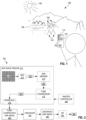
- FIG. 1 illustrates, in an example scenario, one high dynamic range (HDR) camera module 100 with adaptive image data linearization.
- HDR camera module 100 may be implemented in a mobile device 102, such as a mobile phone or tablet. More generally, the camera module 100 may be implemented in an electronic device.
- Example electronic devices in which the HDR camera module 100 may be implemented include (in addition to mobile devices such as mobile phones and tablets) camera devices, display devices, media players, gaming devices, laptops, and desktop computers.
- An electronic device may comprise a housing wherein the HDR camera module 100 is arranged in the housing.
- HDR camera module 100 includes an HDR image sensor 110 and a linearizer 120.
- HDR camera module 100 is configured to generate HDR imagery of a scene.
- the HDR imagery may be an HDR video stream or one or more HDR still images.
- HDR image sensor 110 may be a monochrome image sensor or a color image sensor.
- each HDR image captured by HDR image sensor 110 includes a plurality of color components, for example red, green, and blue.
- HDR camera module 100 generates HDR imagery of a scene 190 that includes both bright areas (e.g., landscape lit by sun 196) and dim areas (e.g., faces 194 of people 192 backlit by sun 196, and the writing on sign 198 also backlit by sun 196).
- the dynamic range of a conventional non-HDR camera would likely be insufficient to capture both the bright areas and the dim areas of scene 190.
- Non-HDR images of scene 190 would therefore likely suffer from faces 194 and writing on sign 198 being underexposed and/or the landscape of scene 190 being overexposed.
- HDR camera module 100 is configured to capture HDR images with an extended dynamic range to better capture HDR scenes such as scene 190.
- FIG. 2 shows HDR camera module 100 in further detail.
- HDR image sensor 110 is configured to generate HDR images 282 at an initial HDR bit depth.
- the output of HDR image sensor 110 is limited to an output bit depth that is less than the initial HDR bit depth, for example for compatibility with device communication protocols.
- HDR image sensor 110 therefore outputs tone-compressed HDR images 284.
- the pixel intensities of each tone-compressed HDR image 284 are the pixel intensities of HDR image 282 mapped to the output bit depth.
- the pixel intensities of tone-compressed HDR image 284 relate to actual scene intensities in a non-linear fashion, so as to optimally retain image information through the tone-compression process.
- Linearizer 120 is configured to re-linearize each tone-compressed HDR image 284 to produce a linearized HDR image 286 having pixel intensities that relate to actual scene intensities in an at least approximately linear fashion.
- Linearizer 120 may also map the pixel intensities of tone-compressed HDR image 284 to a higher bit depth, e.g., the first bit depth, such that the bit depth of linearized HDR image 286 exceeds the bit depth of tone-compressed HDR image 284.
- the bit depth of linearized HDR image 286 may equal the bit depth of pre-tone-compression HDR image 282.
- Linearizer 120 does not require a priori knowledge of the tone-compression function used by HDR image sensor 110 to generate tone-compressed HDR images 284 from pre-tone-compression HDR images 282. Such a priori knowledge is often not available. Instead, linearizer 120 derives, from a frame of tone-compressed HDR image 284, a correspondence between tone-compressed pixel intensities and pre-tone-compression pixel intensities. Linearizer 120 may therefore adapt to changes in the tone-compression function used by HDR image sensor 110. In one scenario, HDR image sensor 110 dynamically adjusts the tone-compression function according to properties of the scene and/or capture settings.
- Linearizer 120 may include a processor and a non-transitory memory encoding machine-readable instructions that, when executed by the processor, control the processor to linearize tone-compressed HDR images 284 as discussed herein.
- Linearizer 120 may be implemented in a digital signal processor (DSP).
- DSP digital signal processor
- FIG. 3 shows a frame 300 of one tone-compressed HDR image 284.
- Frame 300 includes active pixel data 310 and metadata 320.
- Active pixel data 310 may include rows 312 of pixel intensities, wherein each row 312 corresponds to a pixel row of tone-compressed HDR image 284.
- Metadata 320 includes pre-tone-compression information 322, that is, information pertaining to pixel intensities of pre-tone-compression image 282.
- Pre-tone-compression information 322 may be statistical information, such as one or more full or partial histograms of pixel intensities of pre-tone-compression HDR image 282.
- the type of information included in metadata 320 may be configurable via a function call to HDR image sensor 110.
- the term "histogram" of an image denotes the distribution of pixel values of one or more-color components in the image across a number of "bins.”
- bitdepth denotes the pixel precision (e.g., 8-bits, 10-bits, and the like).
- the number of bins may be less than N b .
- a cumulative distribution function (CDF) of the image can be computed as:
- linearizer 120 processes a frame 300 of one tone-compressed HDR image 284, and compares pre-tone-compression information 322 with pixel intensities of active pixel data 310 to determine a correspondence between tone-compressed pixel intensities and pre-tone-compression pixel intensities. Linearizer 120 then applies this correspondence to the tone-compressed pixel intensities of active pixel data 310, of either the same frame 300 or another frame 300 associated with a subsequent tone-compressed HDR image 284, to linearize the tone-compressed pixel intensities of active pixel data 310. The resulting linearized pixel intensities are outputted in linearized HDR image 286.
- HDR camera module 100 may include a master controller 240 that defines the type of information included in metadata 320, such that metadata 320 includes pre-tone-compression information 322. Master controller 240 may further control image capture by HDR image sensor 110.
- FIG. 2 depicts one example implementation of HDR image sensor 110.
- HDR image sensor 110 includes a pixel array 210, an analog-to-digital converter (ADC) 212, an HDR merger 214, a tone-compressor 216, and an interface 218.
- ADC 212 converts analog signals from pixel array 210 to digital image data 281.
- pixel array 210 is spatially-multiplexed and each exposure of pixel array 210 generates two or more images of the scene captured at two or more different exposure settings, respectively.
- an "exposure setting" refers to an exposure time, a gain, or a combination thereof.
- pixel array 210 may be a zig-zag HDR pixel array or a quad-HDR pixel array.
- HDR image sensor 110 is temporally multiplexed and configured to expose pixel array 210 two or more times at two or more different exposure settings, respectively.
- HDR merger 214 generates each pre-tone-compression HDR image 282 from digital image data 281 by merging two or more images of the scene captured at two or more different exposure settings, respectively.
- Tone-compressor 216 tone-compresses each HDR image 282 to produce tone-compressed HDR image 284.
- Interface 218 outputs tone-compressed HDR image 284.
- the bit depth of digital image data 281 is 8 or 10 bits
- the bit depth of each HDR image 282 is 14 or 16 bits
- interface 218 adheres to a Mobile Industry Parallel Interface (MIPI) standard with the output bit depth limited to 10 bits.
- MIPI Mobile Industry Parallel Interface
- tone-compressor 216 compresses the bit depth from 14 or 16 bits to 10 bits.
- HDR camera module 100 may further include an image signal processor (ISP) 230.
- ISP 230 processes linearized HDR image 286 to produce a processed HDR image 288.
- ISP 230 may apply, to linearized HDR image 286, one or more procedures selected from the group consisting of white balancing, color correction, gamma correction, demosaicing, noise reduction, and image sharpening.
- Tone-compressed HDR images 284 are, due to the generally non-linear relationship between tone-compressed pixel intensities and scene intensities, not suitable for display, especially if the tone compression is scene-dependent.
- Linearized HDR images 286, generated by linearizer 120 are display-ready or at least ready for processing by ISP 230.
- many camera modules include an ISP for processing of images outputted by an image sensor, these ISPs are (a) configured to process scene-linear pixel intensities (i.e., pixel intensities that relate to scene intensities in an at least approximately linear fashion) and (b) not configured to linearize tone-compressed pixel intensities where the tone compression is scene-dependent.
- linearizer 120 functions as a necessary preprocessor that linearizes the pixel intensities prior to processing by ISP 230.
- HDR image sensor 110 would be configured to output digital image data 281, prior to HDR merging by HDR merger 214, to perform HDR merging outside HDR image sensor 110.
- typical mobile devices lack such off-sensor HDR merging capability and must therefore rely on tone-compression onboard the HDR image sensor.
- This potential alternative solution is therefore typically not a viable solution, at least for mobile devices.
- linearizer 120 is capable of linearizing tone-compressed pixel intensities in camera modules that (a) lack off-sensor HDR merging capability and therefore must rely on HDR merging onboard the HDR image sensor and (b) impose a limit on the bit depth of the output of the HDR image sensor that is less than the HDR bit depth such that tone-compression is required.
- the linearization performed by linearizer 120 requires no a priori knowledge of the tone-compression function applied onboard the HDR image sensor. Instead linearizer 120 derives the necessary information from tone-compressed HDR image frames outputted by the HDR image sensor. This feature of linearizer 120 enables linearizer 120 to adapt to dynamic changes in the tone-compression function applied onboard the HDR image sensor.
- linearizer 120 may be provided as a standalone product configured for implementation in a camera module together with an HDR image sensor 110 provided by a third party and, optionally, together with an ISP 230 and/or a master controller 240 provided by a third-party.
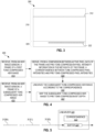
- FIG. 4 illustrates one adaptive method 400 for linearizing a tone-compressed HDR image.
- Method 400 may be performed by linearizer 120.
- Method 400 includes steps 410, 420, 430, and 440.
- Step 410 receives a frame of a first tone-compressed HDR image from an HDR image sensor.
- linearizer 120 receives a frame 300 of a first tone-compressed image 284 from HDR image sensor 110.
- Step 420 derives, from a comparison between active pixel data of the frame and pre-tone-compression pixel intensity information in the metadata of the frame, a correspondence between tone-compressed pixel intensities and pre-tone-compressed pixel intensities.
- linearizer 120 compares active pixel data 310 and pre-tone-compression information 322 of a frame 300 of the first tone-compressed image 284. From this comparison, linearizer 120 derives a correspondence between tone-compressed pixel intensities of the first tone-compressed image 284 and pre-tone-compression pixel intensities of pre-tone-compression HDR image 282.
- the comparison performed in step 420 may consider all tone-compressed pixel intensities of the first tone-compressed image.
- Step 430 receives a frame of a subsequent tone-compressed HDR image from the HDR image sensor. This subsequent tone-compressed HDR image is captured after the first tone-compressed HDR image received in step 410.
- linearizer 120 receives a frame 300 of another tone-compressed image 284 based on a pre-tone-compression HDR image 282 captured by HDR image sensor 110 subsequently to the pre-tone-compression HDR image 282 associated with the tone-compressed image 284 received in step 410.
- Step 440 linearizes the subsequent tone-compressed HDR image, received in step 430, according to the correspondence derived in step 420.
- linearizer 120 linearizes the tone-compressed pixel intensities of the subsequent tone-compressed HDR image 284, received in step 430, according to the correspondence derived in step 420, to generate linearized HDR image 286.
- Step 440 may include a step 442 of mapping the second tone-compressed HDR image to the pre-tone-compression bit depth (or to another bit depth that exceeds the bit depth of the first tone-compressed HDR image).
- Method 400 is particularly well-suited for linearization of a tone-compressed HDR video stream where there is limited time and/or memory available for processing of each frame.
- method 400 may be applied to each tone-compressed HDR image of the video stream, and linearize each tone-compressed HDR image of the video stream according to a correspondence determined for the previous tone-compressed HDR image of the video stream.
- Video processing is often subject to time constraints where all processing must be done at a frame rate that matches the capture frame rate.
- linearizer 120 linearizes frames 300 of each tone-compressed image 284 of a tone-compressed HDR video stream "on the fly". For each frame 300 in this scenario, linearizer 120 (a) serially receives and linearizes different subsets of frame 300 according to a correspondence derived from an immediately preceding frame 300 of the tone-compressed HDR video stream, while synchronously therewith (b) serially extracting, from each of the different subset, the tone-compressed pixel intensities of active pixel data 310. Upon completion of this serial processing, linearizer has collected data for performing step 420 and proceeds to determine a correspondence that will be applied to the next frame 300 of the tone-compressed HDR video stream.
- the tone-compressed pixel intensities collected to perform step 420 may be collected at a reduced resolution.
- the tone-compressed pixel intensities are binned in predefined histogram bins, such that linearizer 120 only needs to count the number of pixels in each bin rather than store the exact tone-compressed pixel intensities for each pixel.
- FIG. 5 illustrates one linearizer 520 for adaptive linearization of a tone-compressed HDR video stream.
- Linearizer 520 is configured to perform an embodiment of method 400.
- Linearizer 520 includes a buffer 524 capable of storing a row 312 of tone-compressed pixel intensities of frame 300 of tone-compressed HDR image 284.
- linearizer 520 serially stores all N rows 312 to buffer 524, one row 312 after the other.
- Each row 312 is processed according to step 440 based upon a correspondence 522 derived from the preceding tone-compressed HDR image 284, and to collect data for step 420 in an iteration of method 400 serving to linearize the subsequent tone-compressed HDR image 284.
- linearizer 520 extracts pre-tone-compression information 322 from metadata 320 and completes step 420 to update correspondence 522.
- buffer 524 may be capable of storing a block of several rows 312, such that linearizer 520 serially processes blocks of rows 312 instead of serially processing individual rows 312.
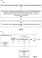
- FIG. 6 illustrates another adaptive method 600 for linearizing a tone-compressed HDR image.
- Method 600 may be performed by linearizer 120.
- Method 600 first performs steps 410 and 420, as discussed above in reference to FIG. 4 .
- a step 640 linearizes the first tone-compressed image according to the correspondence.
- Step 640 is similar to step 440, except that step 640 applies the correspondence to linearization of the same tone-compressed HDR image from which the correspondence has been derived.
- Step 640 may include a step 642 of mapping the first tone-compressed HDR image to the pre-tone-compression bit depth (or to another bit depth that exceeds the bit depth of the first tone-compressed HDR image).
- Method 600 is particularly suitable for processing of tone-compressed HDR still images.
- Still image processing typically is less time-constrained than video stream processing, thus allowing for processing of full frames rather than on-the-fly serial processing of subsets (e.g., rows) of each frame.
- FIG. 7 illustrates one HDR camera module 700 configured to linearize each tone-compressed HDR image, generated by an image sensor of the HDR camera module 700, based upon the tone-compressed HDR image itself.
- HDR camera module 700 includes HDR image sensor 110 and a linearizer 720.
- HDR camera module 700 may further include one or both of ISP 230 and master controller 240.
- HDR camera module 700 is an embodiment of HDR camera module 100
- linearizer 720 is an embodiment of linearizer 120.
- Linearizer 720 is configured to perform an embodiment of method 600.
- Linearizer 720 is communicatively coupled with an image storage 770 capable of storing a full frame 724 of active pixel data 310 of a frame 300 of a tone-compressed HDR image 284.
- linearizer 720 receives frame 300 in step 410 of method 600, and stores all active pixel data 310 of frame 300 in image storage 770 as full frame 724.
- step 420 of method 600 linearizer 720 derives correspondence 522 from frame 300.
- step 640 of method 600 linearizer 720 retrieves full frame 724 from image storage 770 and linearizes the tone-compressed pixel data thereof according to correspondence 522.
- Linearizer 720 may utilize image storage 770 for storage of part of all of linearized HDR image 286 before outputting linearized HDR image 286.
- HDR camera module 700 may be implemented in a mobile device 702 together with image storage 770.
- mobile device 702 is a mobile phone, or tablet, having memory outside HDR camera module 700, where this memory has several functions including serving as image storage 770.
- This memory may be random-access memory (RAM) or a solid state drive (SSD).
- image storage 770 may instead be implemented onboard HDR camera module 700.
- the HDR camera module 700 may more generally be implemented in an electronic device (e.g. of any of the types discussed in connection with FIG. 1 ) together with image storage 770.
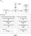
- FIG. 8 illustrates one HDR camera module 800 with machine-readable instructions for adaptive image data linearization.
- HDR camera module 800 includes a processor 810, a non-transitory memory 820, an interface 890, and HDR image sensor 110.
- HDR camera module 800 is an embodiment of HDR camera module 100 and may include one or both of ISP 230 and master controller 240.
- Processor 810 and memory 820 cooperate to form an embodiment of linearizer 120.
- Memory 820 includes machine-readable instructions 830.
- Processor 810 and memory 820 may be implemented in a digital signal processor.
- Machine-readable instructions 830 include data extraction instructions 832, correspondence derivation instructions 834, and linearization instructions 836.
- data extraction instructions 832 control processor 810 to extract data from frame 300 of tone-compressed HDR image 284 received from HDR image sensor 110 via interface 890. Specifically, processor 810 extracts (a) tone-compressed pixel intensities from active pixel data 310 and pre-tone-compression information 322 from metadata 320.
- memory 820 includes buffer 524, and processor 810 utilizes buffer 524 for storage of rows 312 of active pixel data 310, for example as discussed above in reference to FIG. 5 . In another embodiment, not shown in FIG.
- HDR camera module 800 is communicatively coupled with image storage 770 via interface 890, and processor 810 utilizes image storage 770 for storage of active pixel data 310, for example as discussed above in reference to FIG. 7 .
- memory 820 includes a dynamic data storage 860, and processor 810 utilizes dynamic data storage 860 for storage of active pixel data 310 and/or pre-tone-compression information 322.
- correspondence derivation instructions 834 control processor 810 to derive, from a comparison between active pixel data 310 and pre-tone-compression information 322, correspondence 522.
- Processor 810 may store correspondence 522 to dynamic data storage 860.
- linearization instructions 836 control processor 810 to linearize tone-compressed HDR image 284 so as to generate linearized HDR image 286.
- Linearization instructions 836 may control processor 810 to output linearized HDR image 286 via interface 890.
- Processor 810 may utilize buffer 524, dynamic data storage 860, and/or image storage 770 (not shown in FIG. 8 ) for storage of tone-compressed and/or linearized pixel intensities during execution of linearization instructions 863.
- FIG. 9 illustrates yet another adaptive method 900 for linearizing a tone-compressed HDR image.
- Method 900 includes steps 910, 920, 930, and 950.
- Method 900 may be performed by HDR camera module 800.
- Step 910 receives, from an HDR image sensor, a frame of a first tone-compressed HDR image.
- processor 810 receives frame 300 of tone-compressed HDR image 284 from HDR image sensor 110 via interface 890.
- Step 920 extracts, from the frame received in step 410, (a) tone-compressed pixel intensities from active pixel data of the frame and (b) a histogram of pre-tone-compression pixel intensities provided in metadata of the frame.
- processor 810 executes data extraction instructions 832 to (a) extract tone-compressed pixel from active pixel data 310 and (b) extract a pre-tone-compression histogram 864 (see FIG. 8 ) from metadata 320.
- Pre-tone-compression histogram 864 is an example of pre-tone-compression information 322, or included in pre-tone-compression information 322.
- Pre-tone-compression histogram 864 is a histogram of pixel intensities of pre-tone-compression HDR image 282.
- Pre-tone-compression histogram 864 may represent all pixels of pre-tone-compression HDR image 282, or a subset of pixels of pre-tone-compression HDR image 282.
- pre-tone-compression histogram 864 may be a luminance histogram.
- Step 930 derives, from the tone-compressed pixel intensities and the pre-tone-compression histogram, a correspondence between tone-compressed pixel intensities and pre-tone-compression pixel intensities.
- processor 810 executes correspondence derivation instructions 834 to determine correspondence 522.
- Step 950 linearizes at least a portion of active pixel data of the frame of a second tone-compressed HDR image according to the correspondence derived in step 930, thereby generating a linearized HDR image.
- processor 810 executes linearization instructions 836 to linearize tone-compressed HDR image 284 according to correspondence 522, thereby generating linearized HDR image 286.
- the second tone-compressed HDR image is either (a) the first tone-compressed HDR image or (b) a subsequent tone-compressed HDR image captured by the HDR image sensor after capture of the first tone-compressed HDR image received in step 910.
- the first and subsequent tone-compressed HDR images may be consecutive images of a tone-compressed HDR video stream.
- method 900 may further include a step (not shown in FIG. 9 ) of limiting temporal variation, through the video stream, in the correspondence determined in step 930. Such a step may serve to prevent visually apparent discrete changes from frame to frame in the linearized video stream.
- method 900 evaluates deviations between (a) the correspondence determined in step 930 for the currently processed first tone-compressed HDR image and (b) the correspondence determined in step 930 for an immediately preceding first tone-compressed HDR image.
- the threshold value may be defined as a maximum allowed relative difference, for each value of the tone-compressed pixel intensity, between (a) a pre-tone-compression pixel intensity according to the correspondence for the currently processed first tone-compressed HDR image and (b) a pre-tone-compression pixel intensity according to the correspondence for the immediately preceding first tone-compressed HDR image.
- the maximum allowed relative difference is, for example in the range between one and ten percent.
- step 950 linearizes all tone-compressed pixel intensities of the second tone-compressed HDR image according to a correspondence derived from a consideration of all tone-compressed pixel intensities of the first tone-compressed HDR image in step 930. In another embodiment, step 950 linearizes pixel intensities in a spatial sub-region of the second tone-compressed HDR image, according to a correspondence derived from a consideration of tone-compressed pixel intensities of that same spatial sub-region of the first tone-compressed HDR image in step 930.
- step 950 linearizes the first tone-compressed HDR image
- steps 910, 920, 930, and 950 cooperate to form an embodiment of method 600.
- method 900 further includes a step 940, and steps 910, 920, 930, 940, and 950 cooperate to form an embodiment of method 400.
- Step 940 receives, from an HDR image sensor, a frame of a subsequent tone-compressed HDR image.
- processor 810 receives frame 300 of a subsequent tone-compressed HDR image 284 from HDR image sensor 110 via interface 890, wherein the subsequent tone-compressed HDR image 284 has been captured after the first tone-compressed HDR image 284.
- method 900 further includes steps 902, 904, and 906, each of which may be performed by an HDR image sensor such as HDR image sensor 110.
- Step 902 captures raw image data at a capture bit depth.
- pixel array 210 (in cooperation with ADC 212) captures digital image data 281.
- Step 904 merges the raw image data to form an HDR image at a pre-tone-compression bit depth.
- HDR merger 214 merges digital image data 281, obtained at two or more different exposure settings, to form pre-tone-compression HDR image 282.
- Step 906 tone-compresses the HDR image, formed in step 904, to a compressed bit depth that is less than the pre-tone-compression bit depth.
- tone-compressor 216 tone-compresses pre-tone-compression HDR image 282 to generate tone-compressed HDR image 284.
- Method 900 may further include a step 960 of post-processing the linearized HDR image generated in step 950.
- Step 960 may apply one or more processes to the linearized HDR image, for example one or more of white balancing, color correction, gamma correction, demosaicing, noise reduction, and image sharpening.
- ISP 230 processes linearized HDR image 286.
- Embodiments of method 900 that do not include any of steps 902, 904, 906, and 960 may be performed by linearizer 120, for example implemented as processor 810 and memory 820.
- FIGS. 10-13 illustrate one adaptive method 1000 for linearizing a tone-compressed HDR image based upon cumulative distribution functions (CDFs).
- FIG. 10 is a flowchart for method 1000
- FIGS. 11-13 are example diagrams of certain elements of method 1000.
- FIGS. 10-13 are best viewed together in the following description.
- Method 1000 is an embodiment of portion 901 of method 900 (see FIG. 9 ).
- Method 1000 may be performed by linearizer 120, for example implemented as processor 810 and memory 820.
- Method 1000 includes steps 1010, 1020, 1030, and 1050. Steps 1010, 1020, and 1030 cooperate to form an embodiment of step 930, of method 900, that may be encoded in correspondence derivation instructions 834.
- Step 1050 is an embodiment of step 950 of method 900 and may be encoded in linearization instructions 836.
- Step 1010 generates a first CDF of the tone-compressed pixel intensities obtained in step 920.
- step 1010 generates a CDF 1210 (see FIG. 12 ) of tone-compressed pixel intensities of active pixel data 310.
- CDF 1210 may be based upon all tone-compressed pixel intensities of active pixel data 310, or a subset of the tone-compressed pixel intensities of active pixel data 310.
- V C,i may indicate a center value of a range of tone-compressed pixels assigned to bin B C,i or an upper limit for tone-compressed pixels assigned to bin B C,i .
- Step 1020 generates a second CDF of the histogram of pre-tone-compression pixel intensities obtained in step 920.
- FIG. 11 shows one example histogram 1100, where HDR image sensor 110 has binned pre-tone-compression pixel intensities of pre-tone-compression HDR image 282 in bins 1110.
- FIG. 12 shows (schematically) a CDF 1220 of histogram 1100.
- Step 1020 may calculate the second CDF, CDF P , from the histogram of the pre-tone-compression pixel intensities, in a manner similar to the calculation of the first CDF from a histogram of tone-compressed pixel intensities, as discussed above in reference to step 1010.
- Step 1030 determines a correspondence between tone-compressed pixel intensities and pre-tone-compression pixel intensities such that, for each of a plurality of corresponding pairs of a tone-compressed pixel intensity and a pre-tone-compression pixel intensity, the first CDF evaluated at the tone-compressed pixel intensity equals the second CDF evaluated at the pre-tone-compression pixel intensity.
- the correspondence determined by step 1030 is an example of correspondence 522.
- FIG. 12 provides a visual example diagram 1200 of this correspondence, as determined from CDFs 1210 and 1220.
- step 1030 seeks to determine a pre-tone-compressed pixel intensity associated with the same CDF value.
- Diagram 1200 considers a tone-compressed pixel intensity 1212 of tone-compressed HDR image 284.
- the value of CDF 1210 at tone-compressed pixel intensity 1212 is CDF value 1224.
- CDF value 1224 With the knowledge of CDF value 1224, it is possible to read, from diagram 1200 by following the dashed arrows, a pre-tone-compression pixel intensity 1222 of pre-tone-compression HDR image 282 that corresponds to CDF 1220 attaining CDF value 1224.
- tone-compressed pixel intensity 1212 is the 574 th brightest tone-compressed pixel intensity
- pre-tone-compression pixel intensity 1222 is at least approximately the 574 th brightest pre-tone-compression pixel intensity.
- Finite binning resolution in histogram 1100 may result in deviations from an exact match between tone-compressed pixel intensity 1212 and pre-tone-compression pixel intensity 1222.
- diagram 1200 is intended for explanatory purposes, and that step 1030 may be performed numerically and without visually reading a diagram.
- CDF 1210 and/or CDF 1220 may increase in a stepwise fashion, as opposed to a smooth fashion.
- CDF 1220 may have one step for each bin 1110.
- step 1030 considers several different tone-compressed pixel intensities 1212 and finds the corresponding pre-tone-compression pixel intensities 1222.
- pixel intensities throughout method 1000 are grayscale intensities.
- the pixel intensities processed in method 1000 may be (a) color-specific pixel intensities (e.g., red, green, and blue pixel intensities), (b) luminance formed by combining different types of color-specific pixel intensities, or (c) a combination of color-specific pixel intensities and luminance.
- CDFs 1210 and 1220 both represent luminance.
- CDFs 1210 and 1220 represent color-specific pixel intensities for the same, single color component (e.g., green).
- CDF 1210 represents color-specific pixel intensities for a single color component
- CDF 1220 represents luminance.
- FIG. 13 is a diagram 1300 of an example correspondence 1310, determined in step 1030, which shows pre-tone-compression pixel intensity as a function of tone-compressed pixel intensity.
- the pre-tone-compression pixel intensity is generally greater than the tone-compressed pixel intensity, with correspondence 1310 being above the 1:1 correspondence indicated by dashed line 1330.
- Step 1030 may include one of steps 1032, 1034, and 1036.
- Step 1032 generates the correspondence as a look-up table.
- the look-up table lists a plurality of pairs of corresponding tone-compressed and pre-tone-compression pixel intensities, e.g., pairs of tone-compressed pixel intensities 1212 and pre-tone-compression pixel intensities 1222 corresponding to the same CDF value.
- Step 1034 generates the correspondence as a polynomial function, in accordance with the present invention. Step 1034 may determine this polynomial function by fitting to the plurality of pairs of corresponding tone-compressed and pre-tone-compression pixel intensities.
- Step 1036 generates the correspondence as a spline representation having a plurality of polynomial segments, in accordance with the present invention.
- the polynomial segments may be quadratic or cubic.
- Step 1036 may determine this spline representation by spline interpolation between the plurality of pairs of corresponding tone-compressed and pre-tone-compression pixel intensities.
- Step 1050 linearizes at least a portion of the active pixel data of the frame of the first or subsequent tone-compressed HDR image according to the correspondence determined in step 1030.
- Step 1050 may include a step 1052 of mapping the first or subsequent tone-compressed HDR image to the pre-tone-compression bit depth (or to another bit depth that exceeds the pre-tone-compression bit depth).
- step 1050 includes step 1054.
- Step 1054 searches the look-up table for each tone-compressed pixel intensity of the first or subsequent tone-compressed HDR image and reads the corresponding pre-tone-compression pixel intensity, thereby at least approximately re-linearizing the pixel intensities.
- Step 1054 may include a step 1056 of interpolating between entries in the look-up table when a tone-compressed pixel intensity of the active pixel data of the first-subsequent tone-compressed HDR image does not equal a tone-compressed pixel intensity listed in the look-up table.
- step 1050 includes a step 1058 of applying the polynomial function to the tone-compressed pixel intensities. Step 1050 thereby determines corresponding pre-tone-compression pixel intensities, thus at least approximately re-linearizing the pixel intensities.
- step 1050 includes a step 1059 of applying the spline representation to the tone-compressed pixel intensities. Step 1050 thereby determines corresponding pre-tone-compression pixel intensities, thus at least approximately re-linearizing the pixel intensities.
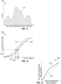
- FIGS. 14 and 15 are visual diagrams of another example of step 1030 of method 1000.
- FIGS. 14 and 15 are best viewed together in the following description.
- the histogram of pre-tone-compression pixel intensities obtained in step 920 is binned logarithmically, such that each bin corresponds to log 2 ( v ), where v is the pre-tone-compression pixel intensity.
- FIG. 14 shows an example histogram 1400 with logarithmic bins 1410. Histogram 1400 has 14 bins corresponding to HDR images 282 having bit depth of 14 bits.
- FIG. 15 is a diagram 1500 that is conceptually similar to diagram 1200 except for being based partly upon logarithmically binned histogram 1400.
- Diagram 1500 plots (a) a CDF 1510 of tone-compressed pixel intensities of active pixel data 310 of a tone-compressed HDR image 284 and (b) a CDF 1520 of histogram 1400.
- CDF 1520 has a pronounced stepwise behavior due to the logarithmic binning of histogram 1400.
- Corresponding pairs of tone-compressed and pre-tone-compression pixel intensities may be determined in a manner similar to that discussed above in reference to FIG. 12 .
- a given tone-compressed pixel intensity 1512 corresponds to a CDF value 1524 of CDF 1510.
- the corresponding pre-tone-compression pixel intensity 1522 may be determined as a pre-tone-compression pixel intensity within the range 1526 of a step of CDF 1520 across CDF value 1524.
- the corresponding pre-tone-compression pixel intensity 1522 is, for example, set to a center-value of range 1526.
- the distribution of pre-tone-compression pixel intensities within range 1526 is assumed to be linear, as indicated by line 1528, and the corresponding pre-tone-compression pixel intensity 1522 is determined as the pre-tone-compression pixel intensity where line 1528 matches CDF value 1524.
- the closest nodes 1530 and 1532 of CDF 1520 bracketing CDF value 1524 are found.
- Lower node 1530 has coordinates ( v P, 0 , CDF P ,0 ), and upper node 1532 has coordinates ( v P ,1 , CDF P ,1 ).
- FIG. 16 illustrates one adaptive method 1600 for linearizing a tone-compressed HDR color image based upon luminance.
- Method 1600 is an embodiment of method 1000.
- Method 1600 includes steps 1610, 1612, 1620, 1630, and 1650. Steps 1610, 1612, 1620, and 1630 cooperate to form an embodiment of step 930, of method 900, that may be encoded in correspondence derivation instructions 834.
- Step 1650 is an embodiment of step 950 of method 900 and may be encoded in linearization instructions 836.
- Step 1610 combines tone-compressed color-specific pixel intensities, of a tone-compressed HDR color image, to form tone-compressed pixel intensities representing luminance.
- red, green, and blue pixel intensities of tone-compressed HDR image 284 are combined to form luminance values corresponding to a tone-compressed HDR luminance image.
- Step 1612 takes the luminance values generated in step 1610 as input and performs step 1010 of method 1000, with the tone-compressed pixel intensities representing luminance, to form a first CDF.
- luminance pixel values generated in step 1610 are processed to generate a luminance-based version of CDF 1210.
- Step 1620 generates a second CDF of a luminance histogram.
- HDR image sensor 110 is configured to output pre-tone-compression histogram 864 as a luminance histogram, and step 1620 forms CDF 1220 of this luminance histogram.
- HDR image sensor 110 is configured to output a pre-tone-compression histogram 864 for each of several color components of HDR image sensor 110, and step 1620 combines these color-specific histograms to form a luminance histogram before forming CDF 1220 of the luminance histogram.
- Step 1630 takes the CDFs generated in steps 1612 and 1620 as input and performs step 1030 of method 1000 with pixel intensities representing luminance. Step 1630 thereby generates a correspondence (e.g., correspondence 522) between tone-compressed luminance and pre-tone-compression luminance. Step 1650 performs step 1050 of method 1000 separately for each color, using the same correspondence for each color. In other words, the correspondence between tone-compressed luminance and pre-tone-compression luminance is applied to each color-specific pixel intensity of the tone-compressed HDR color image.
- the look-up table generated in step 1032 e.g., correspondence 52
- FIG. 17 illustrates one adaptive method 1700 for linearizing a tone-compressed HDR color image based upon pre-tone-compression luminance and a single color component of the tone-compressed HDR color image.
- Method 1700 is an embodiment of method 1000.
- Method 1700 includes steps 1710, 1620, 1730, and 1650.
- Method 1700 is similar to method 1600 except for step 1710 replacing steps 1610 and 1612, and step 1730 replacing step 1630.
- Step 1710 performs step 1010 of method 1000, with the tone-compressed pixel intensities being color-specific pixel intensities representing a single color component of the tone-compressed HDR color image, to form a first CDF.
- green pixel intensities of active pixel data 310 of tone-compressed HDR image 284 are processed to generate a single-color version of CDF 1210.
- Step 1730 takes the CDFs generated in steps 1710 and 1620 as input and performs step 1030 of method 1000 with the tone-compressed pixel intensities representing a single color and the pre-tone-compression pixel intensities representing luminance. Step 1730 thereby generates a correspondence (e.g., correspondence 522) between (a) color-specific tone-compressed pixel intensities, for a single-color component, and (b) pre-tone-compression luminance.
- step 1650 applies the same correspondence to all color components of the tone-compressed HDR color image, even though the correspondence has been determined based upon a single color component of the tone-compressed HDR color image.
- FIG. 18 illustrates one adaptive method 1800 for linearizing a tone-compressed HDR color image based upon a separate consideration of each color component.
- Method 1800 is an embodiment of method 1000.
- Method 1800 may be encoded in machine-readable instructions 830.
- Method 1800 includes three instances of a step 1810. Each instance of step 1810 linearizes a respective color component of the tone-compressed HDR color image according to a correspondence derived exclusively from image data associated with that color component.
- Step 1810(1) performs method 1000 for a first color, e.g., red, based upon first-color tone-compressed pixel intensities and first-color histogram of pre-tone-compression pixel intensities.
- Step 1810(2) performs method 1000 for a second color, e.g., green, based upon second-color tone-compressed pixel intensities and second-color histogram of pre-tone-compression pixel intensities.
- Step 1810(3) performs method 1000 for a third color, e.g., blue, based upon third-color tone-compressed pixel intensities and third-color histogram of pre-tone-compression pixel intensities.
- Method 1800 relies on the HDR image sensor providing pre-tone-compression histogram 864 for each color component.
- FIG. 19 illustrates one adaptive method 1900 for linearizing a tone-compressed HDR color image based in part upon pre-tone-compression pixel intensities of a single color component.
- Method 1900 is an embodiment of method 1000.
- Method 1900 includes steps 1710, 1920, 1930, and 1650.
- Method 1900 is similar to method 1700 except for step 1920 replacing step 1620, and step 1930 replacing step 1730.
- Step 1920 is similar to step 1620 except for being based upon a pre-tone-compression histogram that is specific to a single color component, e.g., green.
- Step 1930 takes the CDFs generated in steps 1710 and 1920 as input and performs step 1030 of method 1000 with tone-compressed pixel intensities and pre-tone-compression pixel intensities representing the single color.
- FIGS. 20 and 21 illustrate one adaptive method 2000 for determining a correspondence between tone-compressed and pre-tone-compression pixel intensities by deriving a directly-matched partial correspondence between the tone-compressed and pre-tone-compression pixel intensities and then extrapolating the directly-matched correspondence.
- Method 2000 is an embodiment of step 1030 of method 1000 and may be encoded in linearization instructions 836.
- FIG. 20 is a flowchart for method 2000
- FIG. 21 is an example diagram illustrating certain elements of method 2000.
- FIGS. 20 and 21 are best viewed together in the following description.
- Method 2000 may be advantageously employed, for example, in situations where the HDR image sensor provides only a partial histogram of the pre-tone-compression pixel intensities and/or in situations where higher pixel intensities are affected by saturation and therefore unsuitable for correspondence derivation.
- Method 2000 includes steps 2010 and 2020.
- Step 2010 determines a directly-matched partial correspondence between tone-compressed and pre-tone-compression pixel intensities, and step 2020 extrapolates the directly-matched partial correspondence.
- step 2010 determines a directly-matched-correspondence between the tone-compressed pixel intensities and the pre-tone-compression pixel intensities.
- step 2010 determines a directly-matched correspondence 2112 between a CDF (e.g., CDF 1210) of tone-compressed pixel intensities of active pixel data 310 of tone-compressed HDR image 284 and a CDF (e.g., CDF 1220) of pre-tone-compression histogram 864.
- Directly-matched correspondence 2112 is determined only for tone-compressed pixel intensities below a cut-off pixel intensity 2120.
- Step 2020 extrapolates the directly-matched-correspondence, determined in step 2010, through the uppermost range to generate the full correspondence between tone-compressed and pre-tone-compression pixel intensities.
- step 2020 extrapolates directly-matched correspondence 2112 beyond cut-off pixel intensity 2120 to determine an extrapolated correspondence 2114.
- Directly-matched correspondence 2112 and extrapolated correspondence 2114 together form a correspondence 2110.
- Correspondence 2110 covers the full range of tone-compressed pixel intensities.
- Step 2020 may include either one of steps 1032 and 1034 of method 1000.
- Step 2020 may use a polynomial fit to or spline representation of directly-matched correspondence 2112, or a portion of directly-matched correspondence 2112 near the cut-off pixel intensity 2120, to determine extrapolated correspondence 2114.
- step 2010 includes steps 2012 and 2013.
- Step 2012 evaluates at least one of the first tone-compressed image (e.g., tone-compressed HDR image 284) and the first cumulative distribution function (e.g., CDF 1210) to determine a cut-off tone-compressed pixel intensity (e.g., cut-off pixel intensity 2120) that excludes saturated tone-compressed pixel intensities.
- Step 2013 defines the partial range as a range of tone-compressed pixel intensities no greater than the cut-off tone-compressed pixel intensity (e.g., cut-off pixel intensity 2120).
- step 2010 includes steps 2014 and 2018.
- Step 2014 evaluates a histogram (e.g., pre-tone-compression histogram 864) of pre-tone-compression pixel intensities, representing only a lower subset of full dynamic range, to determine a cut-off pre-tone-compression pixel intensity.
- Step 2018 defines the partial range of tone-compressed pixel intensities as the number of lowest tone-compressed pixel intensities that equals the number of pre-tone-compression pixel intensities no greater than the cut-off pre-tone-compression pixel intensity determined in step 2014.
- Step 2014 may include a step 2015.
- Step 2015 sets the cut-off pre-tone-compression pixel intensity to the maximum pixel intensity of the histogram (e.g., the uppermost bin of pre-tone-compression histogram 864 having non-zero counts, or the uppermost bin of histogram 1100 or logarithmic histogram 1400 having non-zero counts).
- Each bin B i corresponds to a pre-tone-compression pixel intensities 2 i
- the highest bin with non-zero counts is B N max , wherein N max is a positive integer no greater than N - 1.
- the cut-off pre-tone-compression pixel intensity is set to 2 N max .
- FIG. 22 illustrates one method 2200 for determining a range for derivation of a directly-matched partial correspondence between the tone-compressed and pre-tone-compression pixel intensities.
- Method 2200 may be implemented in step 2010 of method 2000.
- Method 2200 utilizes a logarithmic histogram of pre-tone-compression pixel intensities, such as histogram 1400.
- Method 2200 includes steps 2210, 2220, 2230, and 2240.
- Step 2210 counts the number N SAT of saturated pixels in a tone-compressed HDR image (e.g., tone-compressed HDR image 284).
- Step 2220 identifies bins of a logarithmic pre-tone-compression histogram (e.g., histogram 1400) containing the N SAT uppermost pre-tone-compression pixel intensities. For example, starting from the highest bin of the logarithmic pre-tone-compression histogram step 2220 may descend down through the bins in the following manner.
- a logarithmic pre-tone-compression histogram e.g., histogram 1400
- Step 2230 takes as input the bins of the logarithmic pre-tone-compression histogram and calculates an average bin thereof.
- Step 2230 may calculate a geometric mean of the bins identified in step 2220.
- Step 2240 then limits the range for derivation of a directly-matched partial correspondence between the tone-compressed and pre-tone-compression pixel intensities to bins of the logarithmic pre-tone-compression histogram no greater than the average bin.
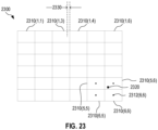
- FIG. 23 illustrates one adaptive method 2300 for linearizing a tone-compressed HDR image according to a spatially varying correspondence between tone-compressed and pre-tone-compressed pixel intensities.
- Method 2300 is an embodiment of steps 920, 930, and 950 of method 900 and may be employed when the HDR image sensor is configured to output a separate pre-tone-compression histogram for each of a plurality of non-overlapping spatial image zones of pre-tone-compression HDR image 282.
- Method 2300 may be encoded in machine-readable instructions 830.
- Method 2300 segregates each of the first and second tone compressed images, discussed above in reference to FIG. 9 , into a plurality of non-overlapping spatial image zones 2310.
- FIG. 23 shows a 6x6 grid of spatial image zones 2310. It is understood that the shaped and/or number of spatial image zones 2310 may differ from that shown in FIG. 23 .
- Method 2300 then repeats steps 920, 930, and 950 of method 900 for each spatial image zone 2310 to determine a separate correspondence between tone-compressed and pre-tone-compression pixel intensities for each spatial image zone 2310.
- Method 2300 may implement method 1000 when performing steps 930 and 950.
- method 2300 is configured to smooth the transition between correspondences determined for adjacent spatial image zones 2310.
- method 2300 when performing step 950, includes, at least for each pixel within a threshold distance of a boundary between adjacent spatial image zones 2310, spatially interpolating the correspondence determined for adjacent spatial image zones based upon position of the pixel. For example, for pixels within a region of spatial image zone 2310(1,3) that is less than distance 2330 from spatial image zone 2310(1,4), the correspondence applicable to that pixel may be found by spatial interpolation between the two correspondences determined for spatial image zones 2310(1,3) and 2310(1,4) according to the exact location of the pixel.
- spatial interpolation is applied to all pixels.
- the correspondence determined for each spatial image zone 2310 is assigned to its center location 2316.
- method 2300 spatially interpolates the correspondence determined for four spatial image zones having respective center location nearest the pixel. For example, for pixel 2320, method 2300 spatially interpolates, from center locations 2316, the four correspondences determined for spatial image zones 2310(5,5) 2310(5,6), 2310(6,5) and 2310(6,6) to the location of pixel 2320.
Description
- This application claims priority to
United States Provisional Patent Application No. 62/885,458, filed 12 August 2019 European Patent Application No. 19191257.5, filed 12 August 2019 - The present application relates to high-dynamic-range (HDR) image sensors, processing of image data generated by HDR image sensors, and the implementation of HDR image sensors and associated processing in mobile devices.
- Numerous methods for high dynamic range (HDR) image capture have been developed over the past several decades. High-end camera systems, found mostly in the professional and scientific domain, typically employ large sensor pixels in conjunction with high bit-depth analog-to-digital conversion circuitry. By virtue of each sensor pixel being large, each sensor pixel has an intrinsically high dynamic range. Therefore, a raw image captured by such a high-end HDR camera system may provide HDR imagery in a single exposure of the sensor. Further aiding the performance of such systems, in both CCD and CMOS designs, readout noise levels have been reduced dramatically, thereby allowing for a single-exposure capture dynamic range exceeding 14 f-stops in high-end HDR camera systems.
- The most widely used HDR cameras, however, are subject to both cost and space constraints, which preclude image sensors with large sensor pixels and high bit-depth analog-to-digital conversion circuitry. Most HDR cameras, such as those onboard mobile devices, instead utilize temporal or spatial multiplexing to capture two or more images of the same scene at two or more different exposure settings, respectively. In the case of two different exposure settings, a low-exposure image provides optimal image data for bright portions of the scene, while a high-exposure image provides optimal image data for dim portions of the scene. The low-exposure image and the high-exposure image are merged, post-capture, to generate an HDR image that spans a higher dynamic range than either one of the low-exposure image and the high-exposure image.
- In temporally-multiplexed HDR imaging, the full pixel array is exposure twice, one time with a long exposure time and/or high gain and one time with a short exposure time and/or low gain. Temporally-multiplexed HDR imaging may utilize more than two different exposure settings to extend the dynamic range even further. Temporally-multiplexed HDR imaging may be carried out with a conventional non-HDR image sensor.
- Spatially-multiplexed HDR imaging, on the other hand, utilizes an HDR-specific pixel array. Different subsets of the pixel array are configured to operate at different respective exposure settings, such that each frame captured by the pixel array includes images captured at the different exposure settings. For example, in the "zig-zag HDR" configuration, the pixel array layout consists of zig-zag lines of pixels, with the layout alternating between low-exposure zig-zag lines and high-exposure zig-zag lines. This layout is superimposed on the conventional Bayer color filter arrangement. In the "quad HDR" configuration, the conventional Bayer color filter arrangement is extended, such that each color filter sits atop a 2x2 pixel group (instead of atop a single pixel), where each 2x2 pixel group consists of one low-exposure pixel, two middle-exposure pixels, and one high-exposure pixel.
-
WO 2018/005705 A1 discloses a method to reconstruct a high dynamic range video signal, a decoder receives parameters in the input bitstream to generate a prediction function. Using the prediction function, it generates a first set of nodes for a first prediction lookup table, wherein each node is characterized by an input node value and an output node value. Then, it modifies the output node values of one or more of the first set of nodes to generate a second set of nodes for a second prediction lookup table, and generates output prediction values using the second lookup table. Low-complexity methods to modify the output node value of a current node in the first set of nodes based on computing modified slopes between the current node and nodes surrounds the current node are presented. -
US 2018/0098094 discloses that a SDR CDF is constructed based on an SDR histogram generated from a distribution of SDR codewords in SDR images. An HDR CDF is constructed based on an HDR histogram generated from a distribution of HDR codewords in HDR images that correspond to the SDR images. A histogram transfer function is generated based on the SDR CDF and the HDR CDF. The SDR images are transmitted along with backward reshaping metadata to recipient devices. The backward reshaping metadata is generated at least in part on the histogram transfer function. -
US 2015/0294180 A1 discloses a histogram equalization apparatus using histogram compression, and the objective is to provide an equalization apparatus which highly compresses a histogram of an input image having a brightness level with a high frequency and lowly compresses the histogram having a brightness level with relatively a lower frequency. - According to the present invention there is provided a high-dynamic-range (HDR) camera module with adaptive image data linearization and an adaptive method for linearizing a tone-compressed HDR image as set out in the independent claims.
-
-
FIG. 1 illustrates, in an example use scenario, a high dynamic range (HDR) camera module with adaptive image data linearization, for illustration purposes. -
FIG. 2 shows the HDR camera module ofFIG. 1 in further detail. -
FIG. 3 shows a frame of a tone-compressed HDR image, for illustration purposes. -
FIG. 4 illustrates an adaptive method for linearizing a tone-compressed HDR image, according to a generic method. -
FIG. 5 illustrates a linearizer for adaptive linearization of a tone-compressed HDR video stream, for illustration purposes. -
FIG. 6 illustrates another adaptive method for linearizing a tone-compressed HDR image, according to generic method. -
FIG. 7 illustrates a HDR camera module configured to linearize each tone-compressed HDR image, generated by an image sensor of the HDR camera module ofFIG. 7 , based upon the tone-compressed HDR image itself, for illustration purposes. -
FIG. 8 illustrates a HDR camera module with machine-readable instructions for adaptive image data linearization, according to a generic method. -
FIG. 9 illustrates yet another adaptive method for linearizing a tone-compressed HDR image, according to an generic method. -
FIG. 10 is a flowchart for an adaptive method for linearizing a tone-compressed HDR image based upon cumulative distribution functions, according to an embodiment. -
FIGS. 11-13 are example diagrams of certain elements of the method ofFIG. 10 . -
FIGS. 14 and 15 are visual diagrams of another example of a correspondence derivation step of the method ofFIG. 10 . -
FIG. 16 illustrates an adaptive method for linearizing a tone-compressed HDR color image based upon luminance, according to an embodiment. -
FIG. 17 illustrates an adaptive method for linearizing a tone-compressed HDR color image based upon pre-tone-compression luminance and a single color component of the tone-compressed HDR color image, according to an embodiment. -
FIG. 18 illustrates an adaptive method for linearizing a tone-compressed HDR color image based upon a separate consideration of each color component, according to an embodiment. -
FIG. 19 illustrates an adaptive method for linearizing a tone-compressed HDR color image based in part upon pre-tone-compression pixel intensities of a single color component, according to an embodiment. -
FIG. 20 is a flowchart for an adaptive method for determining a correspondence between tone-compressed and pre-tone-compression pixel intensities by deriving a directly-matched partial correspondence between the tone-compressed and pre-tone-compression pixel intensities and then extrapolating the directly-matched correspondence, according to an embodiment. -
FIG. 21 is an example diagram illustrating certain elements of the method ofFIG. 20 . -
FIG. 22 illustrates a method for determining a range for derivation of a directly-matched partial correspondence between the tone-compressed and pre-tone-compression pixel intensities. -
FIG. 23 illustrates an adaptive method for linearizing a tone-compressed HDR image according to a spatially varying correspondence between tone-compressed and pre-tone-compressed pixel intensities. -
FIG. 1 illustrates, in an example scenario, one high dynamic range (HDR)camera module 100 with adaptive image data linearization.HDR camera module 100 may be implemented in amobile device 102, such as a mobile phone or tablet. More generally, thecamera module 100 may be implemented in an electronic device. Example electronic devices in which theHDR camera module 100 may be implemented include (in addition to mobile devices such as mobile phones and tablets) camera devices, display devices, media players, gaming devices, laptops, and desktop computers. An electronic device may comprise a housing wherein theHDR camera module 100 is arranged in the housing.HDR camera module 100 includes anHDR image sensor 110 and alinearizer 120.HDR camera module 100 is configured to generate HDR imagery of a scene. The HDR imagery may be an HDR video stream or one or more HDR still images.HDR image sensor 110 may be a monochrome image sensor or a color image sensor. WhenHDR image sensor 110 is a color image sensor, each HDR image captured byHDR image sensor 110 includes a plurality of color components, for example red, green, and blue. - In the example scenario depicted in
FIG. 1 ,HDR camera module 100 generates HDR imagery of ascene 190 that includes both bright areas (e.g., landscape lit by sun 196) and dim areas (e.g., faces 194 ofpeople 192 backlit bysun 196, and the writing onsign 198 also backlit by sun 196). The dynamic range of a conventional non-HDR camera, for example with a bit depth of 8 or 10 bits, would likely be insufficient to capture both the bright areas and the dim areas ofscene 190. Non-HDR images ofscene 190 would therefore likely suffer fromfaces 194 and writing onsign 198 being underexposed and/or the landscape ofscene 190 being overexposed.HDR camera module 100 is configured to capture HDR images with an extended dynamic range to better capture HDR scenes such asscene 190. -
FIG. 2 showsHDR camera module 100 in further detail.HDR image sensor 110 is configured to generateHDR images 282 at an initial HDR bit depth. However, the output ofHDR image sensor 110 is limited to an output bit depth that is less than the initial HDR bit depth, for example for compatibility with device communication protocols.HDR image sensor 110 therefore outputs tone-compressedHDR images 284. The pixel intensities of each tone-compressedHDR image 284 are the pixel intensities ofHDR image 282 mapped to the output bit depth. Generally, the pixel intensities of tone-compressedHDR image 284 relate to actual scene intensities in a non-linear fashion, so as to optimally retain image information through the tone-compression process.Linearizer 120 is configured to re-linearize each tone-compressedHDR image 284 to produce alinearized HDR image 286 having pixel intensities that relate to actual scene intensities in an at least approximately linear fashion.Linearizer 120 may also map the pixel intensities of tone-compressedHDR image 284 to a higher bit depth, e.g., the first bit depth, such that the bit depth oflinearized HDR image 286 exceeds the bit depth of tone-compressedHDR image 284. The bit depth oflinearized HDR image 286 may equal the bit depth of pre-tone-compression HDR image 282. -
Linearizer 120 does not require a priori knowledge of the tone-compression function used byHDR image sensor 110 to generate tone-compressedHDR images 284 from pre-tone-compression HDR images 282. Such a priori knowledge is often not available. Instead,linearizer 120 derives, from a frame of tone-compressedHDR image 284, a correspondence between tone-compressed pixel intensities and pre-tone-compression pixel intensities.Linearizer 120 may therefore adapt to changes in the tone-compression function used byHDR image sensor 110. In one scenario,HDR image sensor 110 dynamically adjusts the tone-compression function according to properties of the scene and/or capture settings.Linearizer 120 may include a processor and a non-transitory memory encoding machine-readable instructions that, when executed by the processor, control the processor to linearize tone-compressedHDR images 284 as discussed herein.Linearizer 120 may be implemented in a digital signal processor (DSP). -
FIG. 3 shows aframe 300 of one tone-compressedHDR image 284.Frame 300 includesactive pixel data 310 andmetadata 320.Active pixel data 310 may includerows 312 of pixel intensities, wherein eachrow 312 corresponds to a pixel row of tone-compressedHDR image 284.Metadata 320 includes pre-tone-compression information 322, that is, information pertaining to pixel intensities of pre-tone-compression image 282. Pre-tone-compression information 322 may be statistical information, such as one or more full or partial histograms of pixel intensities of pre-tone-compression HDR image 282. The type of information included inmetadata 320 may be configurable via a function call toHDR image sensor 110. - As used herein, the term "histogram" of an image denotes the distribution of pixel values of one or more-color components in the image across a number of "bins." For example, the number Nb of bins may be equal to all possible values of a pixel (e.g., Nb = 2bitdepth ), where bitdepth denotes the pixel precision (e.g., 8-bits, 10-bits, and the like). In some embodiments, the number of bins may be less than Nb. For example, and without limitation, given Nb bins and an image with P s(i) pixel values, a histogram hist[] of the image can be computed as follows:wherein fNb (x) denotes a function that maps the value of x into one of the Nb bins. For example, when Nb = 2bitdepth,fNb (x) = x, or for arbitrary Nb


- Given a histogram hist[] for an image, in an embodiment, a cumulative distribution function (CDF) of the image can be computed as:

- Referring again to
FIG. 2 ,linearizer 120 processes aframe 300 of one tone-compressedHDR image 284, and compares pre-tone-compression information 322 with pixel intensities ofactive pixel data 310 to determine a correspondence between tone-compressed pixel intensities and pre-tone-compression pixel intensities.Linearizer 120 then applies this correspondence to the tone-compressed pixel intensities ofactive pixel data 310, of either thesame frame 300 or anotherframe 300 associated with a subsequent tone-compressedHDR image 284, to linearize the tone-compressed pixel intensities ofactive pixel data 310. The resulting linearized pixel intensities are outputted inlinearized HDR image 286. -
HDR camera module 100 may include amaster controller 240 that defines the type of information included inmetadata 320, such thatmetadata 320 includes pre-tone-compression information 322.Master controller 240 may further control image capture byHDR image sensor 110. -
FIG. 2 depicts one example implementation ofHDR image sensor 110. In this implementation,HDR image sensor 110 includes apixel array 210, an analog-to-digital converter (ADC) 212, anHDR merger 214, a tone-compressor 216, and aninterface 218. For each exposure ofpixel array 210,ADC 212 converts analog signals frompixel array 210 todigital image data 281. In one example,pixel array 210 is spatially-multiplexed and each exposure ofpixel array 210 generates two or more images of the scene captured at two or more different exposure settings, respectively. Herein, an "exposure setting" refers to an exposure time, a gain, or a combination thereof. In this example,pixel array 210 may be a zig-zag HDR pixel array or a quad-HDR pixel array. In another example,HDR image sensor 110 is temporally multiplexed and configured to exposepixel array 210 two or more times at two or more different exposure settings, respectively. Regardless of whetherHDR image sensor 110 utilizes spatial or temporal multiplexing,HDR merger 214 generates each pre-tone-compression HDR image 282 fromdigital image data 281 by merging two or more images of the scene captured at two or more different exposure settings, respectively. Tone-compressor 216 tone-compresses eachHDR image 282 to produce tone-compressedHDR image 284.Interface 218 outputs tone-compressedHDR image 284. - In one implementation, the bit depth of
digital image data 281 is 8 or 10 bits, the bit depth of eachHDR image 282 is 14 or 16 bits, whileinterface 218 adheres to a Mobile Industry Parallel Interface (MIPI) standard with the output bit depth limited to 10 bits. In this implementation, tone-compressor 216 compresses the bit depth from 14 or 16 bits to 10 bits. -
HDR camera module 100 may further include an image signal processor (ISP) 230.ISP 230 processes linearizedHDR image 286 to produce a processedHDR image 288.ISP 230 may apply, tolinearized HDR image 286, one or more procedures selected from the group consisting of white balancing, color correction, gamma correction, demosaicing, noise reduction, and image sharpening. - Tone-compressed
HDR images 284 are, due to the generally non-linear relationship between tone-compressed pixel intensities and scene intensities, not suitable for display, especially if the tone compression is scene-dependent.Linearized HDR images 286, generated bylinearizer 120, are display-ready or at least ready for processing byISP 230. Although many camera modules include an ISP for processing of images outputted by an image sensor, these ISPs are (a) configured to process scene-linear pixel intensities (i.e., pixel intensities that relate to scene intensities in an at least approximately linear fashion) and (b) not configured to linearize tone-compressed pixel intensities where the tone compression is scene-dependent. In embodiments ofHDR camera module 100 that includeISP 230,linearizer 120 functions as a necessary preprocessor that linearizes the pixel intensities prior to processing byISP 230. - In a potential alternative solution,
HDR image sensor 110 would be configured to outputdigital image data 281, prior to HDR merging byHDR merger 214, to perform HDR merging outsideHDR image sensor 110. However, except for very high-end systems, typical mobile devices lack such off-sensor HDR merging capability and must therefore rely on tone-compression onboard the HDR image sensor. This potential alternative solution is therefore typically not a viable solution, at least for mobile devices. - To summarize certain advantages,
linearizer 120 is capable of linearizing tone-compressed pixel intensities in camera modules that (a) lack off-sensor HDR merging capability and therefore must rely on HDR merging onboard the HDR image sensor and (b) impose a limit on the bit depth of the output of the HDR image sensor that is less than the HDR bit depth such that tone-compression is required. The linearization performed bylinearizer 120 requires no a priori knowledge of the tone-compression function applied onboard the HDR image sensor. Instead linearizer 120 derives the necessary information from tone-compressed HDR image frames outputted by the HDR image sensor. This feature oflinearizer 120 enableslinearizer 120 to adapt to dynamic changes in the tone-compression function applied onboard the HDR image sensor. - Without departing from the scope hereof,
linearizer 120 may be provided as a standalone product configured for implementation in a camera module together with anHDR image sensor 110 provided by a third party and, optionally, together with anISP 230 and/or amaster controller 240 provided by a third-party. -
FIG. 4 illustrates oneadaptive method 400 for linearizing a tone-compressed HDR image.Method 400 may be performed bylinearizer 120.Method 400 includessteps - Step 410 receives a frame of a first tone-compressed HDR image from an HDR image sensor. In one example of
step 410,linearizer 120 receives aframe 300 of a first tone-compressedimage 284 fromHDR image sensor 110. - Step 420 derives, from a comparison between active pixel data of the frame and pre-tone-compression pixel intensity information in the metadata of the frame, a correspondence between tone-compressed pixel intensities and pre-tone-compressed pixel intensities. In one example of
step 420,linearizer 120 comparesactive pixel data 310 and pre-tone-compression information 322 of aframe 300 of the first tone-compressedimage 284. From this comparison,linearizer 120 derives a correspondence between tone-compressed pixel intensities of the first tone-compressedimage 284 and pre-tone-compression pixel intensities of pre-tone-compression HDR image 282. The comparison performed instep 420 may consider all tone-compressed pixel intensities of the first tone-compressed image. - Step 430 receives a frame of a subsequent tone-compressed HDR image from the HDR image sensor. This subsequent tone-compressed HDR image is captured after the first tone-compressed HDR image received in
step 410. In one example ofstep 430,linearizer 120 receives aframe 300 of another tone-compressedimage 284 based on a pre-tone-compression HDR image 282 captured byHDR image sensor 110 subsequently to the pre-tone-compression HDR image 282 associated with the tone-compressedimage 284 received instep 410. - Step 440 linearizes the subsequent tone-compressed HDR image, received in
step 430, according to the correspondence derived instep 420. In one example ofstep 440,linearizer 120 linearizes the tone-compressed pixel intensities of the subsequent tone-compressedHDR image 284, received instep 430, according to the correspondence derived instep 420, to generatelinearized HDR image 286. Step 440 may include astep 442 of mapping the second tone-compressed HDR image to the pre-tone-compression bit depth (or to another bit depth that exceeds the bit depth of the first tone-compressed HDR image). -
Method 400 is particularly well-suited for linearization of a tone-compressed HDR video stream where there is limited time and/or memory available for processing of each frame. When used to linearize a tone-compressed HDR video stream,method 400 may be applied to each tone-compressed HDR image of the video stream, and linearize each tone-compressed HDR image of the video stream according to a correspondence determined for the previous tone-compressed HDR image of the video stream. Video processing is often subject to time constraints where all processing must be done at a frame rate that matches the capture frame rate. - In one example scenario,
linearizer 120 linearizes frames 300 of each tone-compressedimage 284 of a tone-compressed HDR video stream "on the fly". For eachframe 300 in this scenario, linearizer 120 (a) serially receives and linearizes different subsets offrame 300 according to a correspondence derived from an immediately precedingframe 300 of the tone-compressed HDR video stream, while synchronously therewith (b) serially extracting, from each of the different subset, the tone-compressed pixel intensities ofactive pixel data 310. Upon completion of this serial processing, linearizer has collected data for performingstep 420 and proceeds to determine a correspondence that will be applied to thenext frame 300 of the tone-compressed HDR video stream. It is understood that the tone-compressed pixel intensities collected to performstep 420 may be collected at a reduced resolution. In one example, the tone-compressed pixel intensities are binned in predefined histogram bins, such thatlinearizer 120 only needs to count the number of pixels in each bin rather than store the exact tone-compressed pixel intensities for each pixel. -
FIG. 5 illustrates onelinearizer 520 for adaptive linearization of a tone-compressed HDR video stream.Linearizer 520 is configured to perform an embodiment ofmethod 400.Linearizer 520 includes abuffer 524 capable of storing arow 312 of tone-compressed pixel intensities offrame 300 of tone-compressedHDR image 284. For each tone-compressedHDR image 284,linearizer 520 serially stores allN rows 312 to buffer 524, onerow 312 after the other. Eachrow 312 is processed according to step 440 based upon acorrespondence 522 derived from the preceding tone-compressedHDR image 284, and to collect data forstep 420 in an iteration ofmethod 400 serving to linearize the subsequent tone-compressedHDR image 284. After processing of allrows 312,linearizer 520 extracts pre-tone-compression information 322 frommetadata 320 and completes step 420 to updatecorrespondence 522. - Without departing from the scope hereof,
buffer 524 may be capable of storing a block ofseveral rows 312, such thatlinearizer 520 serially processes blocks ofrows 312 instead of serially processingindividual rows 312. -
FIG. 6 illustrates anotheradaptive method 600 for linearizing a tone-compressed HDR image.Method 600 may be performed bylinearizer 120.Method 600 first performssteps FIG. 4 . After determining the correspondence instep 420 based upon the first tone-compressed image, astep 640 linearizes the first tone-compressed image according to the correspondence. Step 640 is similar to step 440, except thatstep 640 applies the correspondence to linearization of the same tone-compressed HDR image from which the correspondence has been derived. Step 640 may include astep 642 of mapping the first tone-compressed HDR image to the pre-tone-compression bit depth (or to another bit depth that exceeds the bit depth of the first tone-compressed HDR image).Method 600 is particularly suitable for processing of tone-compressed HDR still images. Still image processing typically is less time-constrained than video stream processing, thus allowing for processing of full frames rather than on-the-fly serial processing of subsets (e.g., rows) of each frame. -
FIG. 7 illustrates oneHDR camera module 700 configured to linearize each tone-compressed HDR image, generated by an image sensor of theHDR camera module 700, based upon the tone-compressed HDR image itself.HDR camera module 700 includesHDR image sensor 110 and alinearizer 720.HDR camera module 700 may further include one or both ofISP 230 andmaster controller 240.HDR camera module 700 is an embodiment ofHDR camera module 100, andlinearizer 720 is an embodiment oflinearizer 120. -
Linearizer 720 is configured to perform an embodiment ofmethod 600.Linearizer 720 is communicatively coupled with animage storage 770 capable of storing afull frame 724 ofactive pixel data 310 of aframe 300 of a tone-compressedHDR image 284. In operation,linearizer 720 receivesframe 300 instep 410 ofmethod 600, and stores allactive pixel data 310 offrame 300 inimage storage 770 asfull frame 724. Instep 420 ofmethod 600,linearizer 720 derivescorrespondence 522 fromframe 300. Next, instep 640 ofmethod 600,linearizer 720 retrievesfull frame 724 fromimage storage 770 and linearizes the tone-compressed pixel data thereof according tocorrespondence 522.Linearizer 720 may utilizeimage storage 770 for storage of part of all oflinearized HDR image 286 before outputtinglinearized HDR image 286. -
HDR camera module 700 may be implemented in amobile device 702 together withimage storage 770. In one example,mobile device 702 is a mobile phone, or tablet, having memory outsideHDR camera module 700, where this memory has several functions including serving asimage storage 770. This memory may be random-access memory (RAM) or a solid state drive (SSD). Without departing from the scope hereof,image storage 770 may instead be implemented onboardHDR camera module 700. TheHDR camera module 700 may more generally be implemented in an electronic device (e.g. of any of the types discussed in connection withFIG. 1 ) together withimage storage 770. -
FIG. 8 illustrates oneHDR camera module 800 with machine-readable instructions for adaptive image data linearization.HDR camera module 800 includes aprocessor 810, anon-transitory memory 820, aninterface 890, andHDR image sensor 110.HDR camera module 800 is an embodiment ofHDR camera module 100 and may include one or both ofISP 230 andmaster controller 240.Processor 810 andmemory 820 cooperate to form an embodiment oflinearizer 120.Memory 820 includes machine-readable instructions 830.Processor 810 andmemory 820 may be implemented in a digital signal processor. Machine-readable instructions 830 includedata extraction instructions 832,correspondence derivation instructions 834, and linearizationinstructions 836. - Upon execution by
processor 810,data extraction instructions 832control processor 810 to extract data fromframe 300 of tone-compressedHDR image 284 received fromHDR image sensor 110 viainterface 890. Specifically,processor 810 extracts (a) tone-compressed pixel intensities fromactive pixel data 310 and pre-tone-compression information 322 frommetadata 320. In one embodiment,memory 820 includesbuffer 524, andprocessor 810 utilizesbuffer 524 for storage ofrows 312 ofactive pixel data 310, for example as discussed above in reference toFIG. 5 . In another embodiment, not shown inFIG. 8 ,HDR camera module 800 is communicatively coupled withimage storage 770 viainterface 890, andprocessor 810 utilizesimage storage 770 for storage ofactive pixel data 310, for example as discussed above in reference toFIG. 7 . In yet another embodiment,memory 820 includes adynamic data storage 860, andprocessor 810 utilizesdynamic data storage 860 for storage ofactive pixel data 310 and/or pre-tone-compression information 322. - Upon execution by
processor 810,correspondence derivation instructions 834control processor 810 to derive, from a comparison betweenactive pixel data 310 and pre-tone-compression information 322,correspondence 522.Processor 810 may storecorrespondence 522 todynamic data storage 860. - Upon execution by
processor 810, linearizationinstructions 836control processor 810 to linearize tone-compressedHDR image 284 so as to generatelinearized HDR image 286.Linearization instructions 836 may controlprocessor 810 to output linearizedHDR image 286 viainterface 890.Processor 810 may utilizebuffer 524,dynamic data storage 860, and/or image storage 770 (not shown inFIG. 8 ) for storage of tone-compressed and/or linearized pixel intensities during execution of linearization instructions 863. -
FIG. 9 illustrates yet anotheradaptive method 900 for linearizing a tone-compressed HDR image.Method 900 includessteps Method 900 may be performed byHDR camera module 800. - Step 910 receives, from an HDR image sensor, a frame of a first tone-compressed HDR image. In one example of
step 910,processor 810 receivesframe 300 of tone-compressedHDR image 284 fromHDR image sensor 110 viainterface 890. - Step 920 extracts, from the frame received in
step 410, (a) tone-compressed pixel intensities from active pixel data of the frame and (b) a histogram of pre-tone-compression pixel intensities provided in metadata of the frame. In one example ofstep 920,processor 810 executesdata extraction instructions 832 to (a) extract tone-compressed pixel fromactive pixel data 310 and (b) extract a pre-tone-compression histogram 864 (seeFIG. 8 ) frommetadata 320. Pre-tone-compression histogram 864 is an example of pre-tone-compression information 322, or included in pre-tone-compression information 322. Pre-tone-compression histogram 864 is a histogram of pixel intensities of pre-tone-compression HDR image 282. Pre-tone-compression histogram 864 may represent all pixels of pre-tone-compression HDR image 282, or a subset of pixels of pre-tone-compression HDR image 282. For HDR color images, pre-tone-compression histogram 864 may be a luminance histogram. - Step 930 derives, from the tone-compressed pixel intensities and the pre-tone-compression histogram, a correspondence between tone-compressed pixel intensities and pre-tone-compression pixel intensities. In one example of
step 930,processor 810 executescorrespondence derivation instructions 834 to determinecorrespondence 522. - Step 950 linearizes at least a portion of active pixel data of the frame of a second tone-compressed HDR image according to the correspondence derived in
step 930, thereby generating a linearized HDR image. In one example ofstep 940,processor 810 executes linearizationinstructions 836 to linearize tone-compressedHDR image 284 according tocorrespondence 522, thereby generatinglinearized HDR image 286. The second tone-compressed HDR image is either (a) the first tone-compressed HDR image or (b) a subsequent tone-compressed HDR image captured by the HDR image sensor after capture of the first tone-compressed HDR image received instep 910. The first and subsequent tone-compressed HDR images may be consecutive images of a tone-compressed HDR video stream. - When used to linearize a tone-compressed HDR video stream,
method 900 may further include a step (not shown inFIG. 9 ) of limiting temporal variation, through the video stream, in the correspondence determined instep 930. Such a step may serve to prevent visually apparent discrete changes from frame to frame in the linearized video stream. In one implementation, performed betweensteps method 900 evaluates deviations between (a) the correspondence determined instep 930 for the currently processed first tone-compressed HDR image and (b) the correspondence determined instep 930 for an immediately preceding first tone-compressed HDR image. If a deviation exceeds a threshold value, the correspondence for the currently processed first tone-compressed HDR image is modified to more closely resemble the correspondence for the immediately preceding first tone-compressed HDR image such that no deviations exceeds the threshold value. The threshold value may be defined as a maximum allowed relative difference, for each value of the tone-compressed pixel intensity, between (a) a pre-tone-compression pixel intensity according to the correspondence for the currently processed first tone-compressed HDR image and (b) a pre-tone-compression pixel intensity according to the correspondence for the immediately preceding first tone-compressed HDR image. The maximum allowed relative difference is, for example in the range between one and ten percent. - In one embodiment, step 950 linearizes all tone-compressed pixel intensities of the second tone-compressed HDR image according to a correspondence derived from a consideration of all tone-compressed pixel intensities of the first tone-compressed HDR image in
step 930. In another embodiment, step 950 linearizes pixel intensities in a spatial sub-region of the second tone-compressed HDR image, according to a correspondence derived from a consideration of tone-compressed pixel intensities of that same spatial sub-region of the first tone-compressed HDR image instep 930. - In embodiments where
step 950 linearizes the first tone-compressed HDR image, steps 910, 920, 930, and 950 cooperate to form an embodiment ofmethod 600. In embodiments wherestep 950 linearizes a subsequent tone-compressed HDR image,method 900 further includes astep 940, and steps 910, 920, 930, 940, and 950 cooperate to form an embodiment ofmethod 400. Step 940 receives, from an HDR image sensor, a frame of a subsequent tone-compressed HDR image. In one example ofstep 940,processor 810 receivesframe 300 of a subsequent tone-compressedHDR image 284 fromHDR image sensor 110 viainterface 890, wherein the subsequent tone-compressedHDR image 284 has been captured after the first tone-compressedHDR image 284. - In certain embodiments,
method 900 further includessteps HDR image sensor 110. Step 902 captures raw image data at a capture bit depth. In one example ofstep 902, pixel array 210 (in cooperation with ADC 212) capturesdigital image data 281. Step 904 merges the raw image data to form an HDR image at a pre-tone-compression bit depth. In one example ofstep 904,HDR merger 214 mergesdigital image data 281, obtained at two or more different exposure settings, to form pre-tone-compression HDR image 282. Step 906 tone-compresses the HDR image, formed instep 904, to a compressed bit depth that is less than the pre-tone-compression bit depth. In one example of step 906, tone-compressor 216 tone-compresses pre-tone-compression HDR image 282 to generate tone-compressedHDR image 284. -
Method 900 may further include astep 960 of post-processing the linearized HDR image generated instep 950. Step 960 may apply one or more processes to the linearized HDR image, for example one or more of white balancing, color correction, gamma correction, demosaicing, noise reduction, and image sharpening. In one example ofstep 960,ISP 230 processes linearizedHDR image 286. - Embodiments of
method 900 that do not include any ofsteps linearizer 120, for example implemented asprocessor 810 andmemory 820. -
FIGS. 10-13 illustrate oneadaptive method 1000 for linearizing a tone-compressed HDR image based upon cumulative distribution functions (CDFs).FIG. 10 is a flowchart formethod 1000, andFIGS. 11-13 are example diagrams of certain elements ofmethod 1000.FIGS. 10-13 are best viewed together in the following description. -
Method 1000 is an embodiment ofportion 901 of method 900 (seeFIG. 9 ).Method 1000 may be performed bylinearizer 120, for example implemented asprocessor 810 andmemory 820.Method 1000 includessteps Steps step 930, ofmethod 900, that may be encoded incorrespondence derivation instructions 834.Step 1050 is an embodiment ofstep 950 ofmethod 900 and may be encoded inlinearization instructions 836. -
Step 1010 generates a first CDF of the tone-compressed pixel intensities obtained instep 920. In one example ofstep 1010,step 1010 generates a CDF 1210 (seeFIG. 12 ) of tone-compressed pixel intensities ofactive pixel data 310.CDF 1210 may be based upon all tone-compressed pixel intensities ofactive pixel data 310, or a subset of the tone-compressed pixel intensities ofactive pixel data 310. The first CDF may be generated by (a) binning the tone-compressed pixel intensities into NC bins BC,i, wherein i = 0,1, ..., NC - 1 and each bin BC,i corresponds to a tone-compressed pixel intensity VC,i and has a count f(VC,i ) , and (b) calculating the first CDF as


-
Step 1020 generates a second CDF of the histogram of pre-tone-compression pixel intensities obtained instep 920.FIG. 11 shows oneexample histogram 1100, whereHDR image sensor 110 has binned pre-tone-compression pixel intensities of pre-tone-compression HDR image 282 inbins 1110.FIG. 12 shows (schematically) aCDF 1220 ofhistogram 1100.Step 1020 may calculate the second CDF, CDFP , from the histogram of the pre-tone-compression pixel intensities, in a manner similar to the calculation of the first CDF from a histogram of tone-compressed pixel intensities, as discussed above in reference to step 1010. -
Step 1030 determines a correspondence between tone-compressed pixel intensities and pre-tone-compression pixel intensities such that, for each of a plurality of corresponding pairs of a tone-compressed pixel intensity and a pre-tone-compression pixel intensity, the first CDF evaluated at the tone-compressed pixel intensity equals the second CDF evaluated at the pre-tone-compression pixel intensity. In other words, for any instance uC (i) of the tone-compressed pixel intensities, the corresponding pre-tone-compressed pixel intensity vP is determined as a pre-tone-compressed pixel intensity that fulfils the equation
step 1030 is an example ofcorrespondence 522. -
FIG. 12 provides a visual example diagram 1200 of this correspondence, as determined fromCDFs step 1030 seeks to determine a pre-tone-compressed pixel intensity associated with the same CDF value. Diagram 1200 considers a tone-compressedpixel intensity 1212 of tone-compressedHDR image 284. The value ofCDF 1210 at tone-compressedpixel intensity 1212 isCDF value 1224. With the knowledge ofCDF value 1224, it is possible to read, from diagram 1200 by following the dashed arrows, a pre-tone-compression pixel intensity 1222 of pre-tone-compression HDR image 282 that corresponds toCDF 1220 attainingCDF value 1224. As an example, if tone-compressedpixel intensity 1212 is the 574th brightest tone-compressed pixel intensity, pre-tone-compression pixel intensity 1222 is at least approximately the 574th brightest pre-tone-compression pixel intensity. Finite binning resolution inhistogram 1100 may result in deviations from an exact match between tone-compressedpixel intensity 1212 and pre-tone-compression pixel intensity 1222. It is understood that diagram 1200 is intended for explanatory purposes, and thatstep 1030 may be performed numerically and without visually reading a diagram. It is further understood thatCDF 1210 and/orCDF 1220 may increase in a stepwise fashion, as opposed to a smooth fashion. For example,CDF 1220 may have one step for eachbin 1110. In such cases, interpolation between adjacent steps ofCDF 1220 may be used to determine pre-tone-compression pixel intensity 1222, for example as discussed below in reference toFIG. 15 . Continuing with diagram 1200 as a visual example,step 1030 considers several different tone-compressedpixel intensities 1212 and finds the corresponding pre-tone-compression pixel intensities 1222. - When
method 1000 is used for monochrome image processing, pixel intensities throughoutmethod 1000 are grayscale intensities. Whenmethod 1000 is used for color image processing, the pixel intensities processed inmethod 1000 may be (a) color-specific pixel intensities (e.g., red, green, and blue pixel intensities), (b) luminance formed by combining different types of color-specific pixel intensities, or (c) a combination of color-specific pixel intensities and luminance. In one example, CDFs 1210 and 1220 both represent luminance. In another example, CDFs 1210 and 1220 represent color-specific pixel intensities for the same, single color component (e.g., green). In yet another example,CDF 1210 represents color-specific pixel intensities for a single color component, whileCDF 1220 represents luminance. Certain embodiments ofmethod 1000, specifically tailored to color image processing, are discussed below in reference toFIGS. 16-19 . -
FIG. 13 is a diagram 1300 of anexample correspondence 1310, determined instep 1030, which shows pre-tone-compression pixel intensity as a function of tone-compressed pixel intensity. In this example, the pre-tone-compression pixel intensity is generally greater than the tone-compressed pixel intensity, withcorrespondence 1310 being above the 1:1 correspondence indicated by dashedline 1330. -
Step 1030 may include one ofsteps Step 1032 generates the correspondence as a look-up table. The look-up table lists a plurality of pairs of corresponding tone-compressed and pre-tone-compression pixel intensities, e.g., pairs of tone-compressedpixel intensities 1212 and pre-tone-compression pixel intensities 1222 corresponding to the same CDF value.Step 1034 generates the correspondence as a polynomial function, in accordance with the present invention.Step 1034 may determine this polynomial function by fitting to the plurality of pairs of corresponding tone-compressed and pre-tone-compression pixel intensities.Step 1036 generates the correspondence as a spline representation having a plurality of polynomial segments, in accordance with the present invention. The polynomial segments may be quadratic or cubic.Step 1036 may determine this spline representation by spline interpolation between the plurality of pairs of corresponding tone-compressed and pre-tone-compression pixel intensities. -
Step 1050 linearizes at least a portion of the active pixel data of the frame of the first or subsequent tone-compressed HDR image according to the correspondence determined instep 1030.Step 1050 may include a step 1052 of mapping the first or subsequent tone-compressed HDR image to the pre-tone-compression bit depth (or to another bit depth that exceeds the pre-tone-compression bit depth). - In embodiments of
method 1000 that includestep 1032,step 1050 includesstep 1054.Step 1054 searches the look-up table for each tone-compressed pixel intensity of the first or subsequent tone-compressed HDR image and reads the corresponding pre-tone-compression pixel intensity, thereby at least approximately re-linearizing the pixel intensities.Step 1054 may include astep 1056 of interpolating between entries in the look-up table when a tone-compressed pixel intensity of the active pixel data of the first-subsequent tone-compressed HDR image does not equal a tone-compressed pixel intensity listed in the look-up table. - In embodiments of
method 1000 that includestep 1034,step 1050 includes a step 1058 of applying the polynomial function to the tone-compressed pixel intensities.Step 1050 thereby determines corresponding pre-tone-compression pixel intensities, thus at least approximately re-linearizing the pixel intensities. In embodiments ofmethod 1000 that includestep 1036,step 1050 includes a step 1059 of applying the spline representation to the tone-compressed pixel intensities.Step 1050 thereby determines corresponding pre-tone-compression pixel intensities, thus at least approximately re-linearizing the pixel intensities. -
FIGS. 14 and 15 are visual diagrams of another example ofstep 1030 ofmethod 1000.FIGS. 14 and 15 are best viewed together in the following description. In this example, the histogram of pre-tone-compression pixel intensities obtained instep 920 is binned logarithmically, such that each bin corresponds to log2 (v), where v is the pre-tone-compression pixel intensity.FIG. 14 shows anexample histogram 1400 withlogarithmic bins 1410.Histogram 1400 has 14 bins corresponding toHDR images 282 having bit depth of 14 bits.FIG. 15 is a diagram 1500 that is conceptually similar to diagram 1200 except for being based partly upon logarithmically binnedhistogram 1400. Diagram 1500 plots (a) aCDF 1510 of tone-compressed pixel intensities ofactive pixel data 310 of a tone-compressedHDR image 284 and (b) aCDF 1520 ofhistogram 1400.CDF 1520 has a pronounced stepwise behavior due to the logarithmic binning ofhistogram 1400. Corresponding pairs of tone-compressed and pre-tone-compression pixel intensities may be determined in a manner similar to that discussed above in reference toFIG. 12 . A given tone-compressedpixel intensity 1512 corresponds to aCDF value 1524 ofCDF 1510. - The corresponding pre-tone-
compression pixel intensity 1522 may be determined as a pre-tone-compression pixel intensity within therange 1526 of a step ofCDF 1520 acrossCDF value 1524. The corresponding pre-tone-compression pixel intensity 1522 is, for example, set to a center-value ofrange 1526. In an alternative example, the distribution of pre-tone-compression pixel intensities withinrange 1526 is assumed to be linear, as indicated byline 1528, and the corresponding pre-tone-compression pixel intensity 1522 is determined as the pre-tone-compression pixel intensity whereline 1528matches CDF value 1524. In one implementation, using such linear interpolation, theclosest nodes CDF 1520bracketing CDF value 1524 are found.Lower node 1530 has coordinates (v P,0, CDF P,0), andupper node 1532 has coordinates (v P,1, CDF P,1). The pre-tone-compression pixel intensity vP corresponding to tone-compressedpixel intensity 1512, uC (i), may then be interpolated according to the expression
-
FIG. 16 illustrates oneadaptive method 1600 for linearizing a tone-compressed HDR color image based upon luminance.Method 1600 is an embodiment ofmethod 1000.Method 1600 includessteps Steps step 930, ofmethod 900, that may be encoded incorrespondence derivation instructions 834.Step 1650 is an embodiment ofstep 950 ofmethod 900 and may be encoded inlinearization instructions 836. -
Step 1610 combines tone-compressed color-specific pixel intensities, of a tone-compressed HDR color image, to form tone-compressed pixel intensities representing luminance. In one example ofstep 1610, red, green, and blue pixel intensities of tone-compressedHDR image 284 are combined to form luminance values corresponding to a tone-compressed HDR luminance image. -
Step 1612 takes the luminance values generated instep 1610 as input and performsstep 1010 ofmethod 1000, with the tone-compressed pixel intensities representing luminance, to form a first CDF. In one example ofstep 1612, luminance pixel values generated instep 1610 are processed to generate a luminance-based version ofCDF 1210. -
Step 1620 generates a second CDF of a luminance histogram. In one example ofstep 1620,HDR image sensor 110 is configured to output pre-tone-compression histogram 864 as a luminance histogram, and step 1620forms CDF 1220 of this luminance histogram. In another example ofstep 1620,HDR image sensor 110 is configured to output a pre-tone-compression histogram 864 for each of several color components ofHDR image sensor 110, andstep 1620 combines these color-specific histograms to form a luminance histogram before formingCDF 1220 of the luminance histogram. -
Step 1630 takes the CDFs generated insteps step 1030 ofmethod 1000 with pixel intensities representing luminance.Step 1630 thereby generates a correspondence (e.g., correspondence 522) between tone-compressed luminance and pre-tone-compression luminance.Step 1650 performsstep 1050 ofmethod 1000 separately for each color, using the same correspondence for each color. In other words, the correspondence between tone-compressed luminance and pre-tone-compression luminance is applied to each color-specific pixel intensity of the tone-compressed HDR color image. In one example ofstep 1650, (a) tone-compressed red pixel intensities uR of tone-compressedHDR image 284 are scaled to generate linearized red pixel intensities vR according to the expression
step 1630, (b) tone-compressed green pixel intensities uG of tone-compressedHDR image 284 are scaled to generate linearized green pixel intensities vG according to the expression
HDR image 284 are scaled to generate linearized blue pixel intensities vB according to the expression
FIGS. 10 , the look-up table generated in step 1032 (e.g., correspondence 522) may tabulate the ratio LP /LC as a function of LC. -
FIG. 17 illustrates oneadaptive method 1700 for linearizing a tone-compressed HDR color image based upon pre-tone-compression luminance and a single color component of the tone-compressed HDR color image.Method 1700 is an embodiment ofmethod 1000.Method 1700 includessteps Method 1700 is similar tomethod 1600 except forstep 1710 replacingsteps step 1630. -
Step 1710 performsstep 1010 ofmethod 1000, with the tone-compressed pixel intensities being color-specific pixel intensities representing a single color component of the tone-compressed HDR color image, to form a first CDF. In one example ofstep 1710, green pixel intensities ofactive pixel data 310 of tone-compressedHDR image 284 are processed to generate a single-color version ofCDF 1210. -
Step 1730 takes the CDFs generated insteps step 1030 ofmethod 1000 with the tone-compressed pixel intensities representing a single color and the pre-tone-compression pixel intensities representing luminance.Step 1730 thereby generates a correspondence (e.g., correspondence 522) between (a) color-specific tone-compressed pixel intensities, for a single-color component, and (b) pre-tone-compression luminance. Inmethod 1700,step 1650 applies the same correspondence to all color components of the tone-compressed HDR color image, even though the correspondence has been determined based upon a single color component of the tone-compressed HDR color image. -
FIG. 18 illustrates oneadaptive method 1800 for linearizing a tone-compressed HDR color image based upon a separate consideration of each color component.Method 1800 is an embodiment ofmethod 1000.Method 1800 may be encoded in machine-readable instructions 830.Method 1800 includes three instances of astep 1810. Each instance ofstep 1810 linearizes a respective color component of the tone-compressed HDR color image according to a correspondence derived exclusively from image data associated with that color component. - Step 1810(1) performs
method 1000 for a first color, e.g., red, based upon first-color tone-compressed pixel intensities and first-color histogram of pre-tone-compression pixel intensities. Step 1810(2) performsmethod 1000 for a second color, e.g., green, based upon second-color tone-compressed pixel intensities and second-color histogram of pre-tone-compression pixel intensities. Step 1810(3) performsmethod 1000 for a third color, e.g., blue, based upon third-color tone-compressed pixel intensities and third-color histogram of pre-tone-compression pixel intensities.Method 1800 relies on the HDR image sensor providing pre-tone-compression histogram 864 for each color component. -
FIG. 19 illustrates oneadaptive method 1900 for linearizing a tone-compressed HDR color image based in part upon pre-tone-compression pixel intensities of a single color component.Method 1900 is an embodiment ofmethod 1000.Method 1900 includessteps Method 1900 is similar tomethod 1700 except forstep 1920 replacingstep 1620, and step 1930 replacingstep 1730.Step 1920 is similar to step 1620 except for being based upon a pre-tone-compression histogram that is specific to a single color component, e.g., green.Step 1930 takes the CDFs generated insteps step 1030 ofmethod 1000 with tone-compressed pixel intensities and pre-tone-compression pixel intensities representing the single color. -
FIGS. 20 and21 illustrate oneadaptive method 2000 for determining a correspondence between tone-compressed and pre-tone-compression pixel intensities by deriving a directly-matched partial correspondence between the tone-compressed and pre-tone-compression pixel intensities and then extrapolating the directly-matched correspondence.Method 2000 is an embodiment ofstep 1030 ofmethod 1000 and may be encoded inlinearization instructions 836.FIG. 20 is a flowchart formethod 2000, andFIG. 21 is an example diagram illustrating certain elements ofmethod 2000.FIGS. 20 and21 are best viewed together in the following description. -
Method 2000 may be advantageously employed, for example, in situations where the HDR image sensor provides only a partial histogram of the pre-tone-compression pixel intensities and/or in situations where higher pixel intensities are affected by saturation and therefore unsuitable for correspondence derivation.Method 2000 includessteps Step 2010 determines a directly-matched partial correspondence between tone-compressed and pre-tone-compression pixel intensities, andstep 2020 extrapolates the directly-matched partial correspondence. - For a partial range of tone-compressed pixel intensities of a tone-compressed HDR image, excluding an uppermost range of the tone-compressed pixel intensities,
step 2010 determines a directly-matched-correspondence between the tone-compressed pixel intensities and the pre-tone-compression pixel intensities. In one example, illustrated inFIG. 21 ,step 2010 determines a directly-matchedcorrespondence 2112 between a CDF (e.g., CDF 1210) of tone-compressed pixel intensities ofactive pixel data 310 of tone-compressedHDR image 284 and a CDF (e.g., CDF 1220) of pre-tone-compression histogram 864. Directly-matchedcorrespondence 2112 is determined only for tone-compressed pixel intensities below a cut-offpixel intensity 2120. -
Step 2020 extrapolates the directly-matched-correspondence, determined instep 2010, through the uppermost range to generate the full correspondence between tone-compressed and pre-tone-compression pixel intensities. In one example ofstep 2020, illustrated inFIG. 21 ,step 2020 extrapolates directly-matchedcorrespondence 2112 beyond cut-offpixel intensity 2120 to determine an extrapolatedcorrespondence 2114. Directly-matchedcorrespondence 2112 and extrapolatedcorrespondence 2114 together form acorrespondence 2110.Correspondence 2110 covers the full range of tone-compressed pixel intensities.Step 2020 may include either one ofsteps method 1000.Step 2020 may use a polynomial fit to or spline representation of directly-matchedcorrespondence 2112, or a portion of directly-matchedcorrespondence 2112 near the cut-offpixel intensity 2120, to determine extrapolatedcorrespondence 2114. - In one embodiment,
step 2010 includessteps Step 2012 evaluates at least one of the first tone-compressed image (e.g., tone-compressed HDR image 284) and the first cumulative distribution function (e.g., CDF 1210) to determine a cut-off tone-compressed pixel intensity (e.g., cut-off pixel intensity 2120) that excludes saturated tone-compressed pixel intensities.Step 2013 defines the partial range as a range of tone-compressed pixel intensities no greater than the cut-off tone-compressed pixel intensity (e.g., cut-off pixel intensity 2120). - In another embodiment,
step 2010 includessteps Step 2014 evaluates a histogram (e.g., pre-tone-compression histogram 864) of pre-tone-compression pixel intensities, representing only a lower subset of full dynamic range, to determine a cut-off pre-tone-compression pixel intensity.Step 2018 defines the partial range of tone-compressed pixel intensities as the number of lowest tone-compressed pixel intensities that equals the number of pre-tone-compression pixel intensities no greater than the cut-off pre-tone-compression pixel intensity determined instep 2014. -
Step 2014 may include astep 2015.Step 2015 sets the cut-off pre-tone-compression pixel intensity to the maximum pixel intensity of the histogram (e.g., the uppermost bin of pre-tone-compression histogram 864 having non-zero counts, or the uppermost bin ofhistogram 1100 orlogarithmic histogram 1400 having non-zero counts). In one example, the histogram is logarithmic and has N bins Bi , i = 0,1, ... , N - 1. Each bin Bi corresponds to a pre-tone-compression pixel intensities 2 i , and the highest bin with non-zero counts is B Nmax , wherein N max is a positive integer no greater than N - 1. In this example, the cut-off pre-tone-compression pixel intensity is set to 2 Nmax . -
FIG. 22 illustrates onemethod 2200 for determining a range for derivation of a directly-matched partial correspondence between the tone-compressed and pre-tone-compression pixel intensities.Method 2200 may be implemented instep 2010 ofmethod 2000.Method 2200 utilizes a logarithmic histogram of pre-tone-compression pixel intensities, such ashistogram 1400.Method 2200 includessteps -
Step 2210 counts the number N SAT of saturated pixels in a tone-compressed HDR image (e.g., tone-compressed HDR image 284).Step 2220 identifies bins of a logarithmic pre-tone-compression histogram (e.g., histogram 1400) containing the N SAT uppermost pre-tone-compression pixel intensities. For example, starting from the highest bin of the logarithmic pre-tone-compression histogram step 2220 may descend down through the bins in the following manner. For each bin of the logarithmic pre-tone-compression histogram, a counting variable is set to N SAT,i = min(N SAT, Ni ), where Ni is the count for the i'th bin, and N SAT reset to N SAT = N SAT - Ni . This process continues until N SAT is less than or equal to zero. -
Step 2230 takes as input the bins of the logarithmic pre-tone-compression histogram and calculates an average bin thereof.Step 2230 may calculate a geometric mean of the bins identified instep 2220. In one example, the average bin is calculated as
Step 2240 then limits the range for derivation of a directly-matched partial correspondence between the tone-compressed and pre-tone-compression pixel intensities to bins of the logarithmic pre-tone-compression histogram no greater than the average bin. -
FIG. 23 illustrates oneadaptive method 2300 for linearizing a tone-compressed HDR image according to a spatially varying correspondence between tone-compressed and pre-tone-compressed pixel intensities.Method 2300 is an embodiment ofsteps method 900 and may be employed when the HDR image sensor is configured to output a separate pre-tone-compression histogram for each of a plurality of non-overlapping spatial image zones of pre-tone-compression HDR image 282.Method 2300 may be encoded in machine-readable instructions 830. -
Method 2300 segregates each of the first and second tone compressed images, discussed above in reference toFIG. 9 , into a plurality of non-overlapping spatial image zones 2310.FIG. 23 shows a 6x6 grid of spatial image zones 2310. It is understood that the shaped and/or number of spatial image zones 2310 may differ from that shown inFIG. 23 .Method 2300 then repeatssteps method 900 for each spatial image zone 2310 to determine a separate correspondence between tone-compressed and pre-tone-compression pixel intensities for each spatial image zone 2310.Method 2300 may implementmethod 1000 when performingsteps - In certain embodiments,
method 2300 is configured to smooth the transition between correspondences determined for adjacent spatial image zones 2310. In one such embodiment,method 2300, when performingstep 950, includes, at least for each pixel within a threshold distance of a boundary between adjacent spatial image zones 2310, spatially interpolating the correspondence determined for adjacent spatial image zones based upon position of the pixel. For example, for pixels within a region of spatial image zone 2310(1,3) that is less thandistance 2330 from spatial image zone 2310(1,4), the correspondence applicable to that pixel may be found by spatial interpolation between the two correspondences determined for spatial image zones 2310(1,3) and 2310(1,4) according to the exact location of the pixel. - In another embodiment, configured to smooth the transition between correspondences determined for adjacent spatial image zones 2310, spatial interpolation is applied to all pixels. In this embodiment, the correspondence determined for each spatial image zone 2310 is assigned to its center location 2316. For each pixel of the tone-compressed HDR image, when
method 2300 performsstep 950,method 2300 spatially interpolates the correspondence determined for four spatial image zones having respective center location nearest the pixel. For example, forpixel 2320,method 2300 spatially interpolates, from center locations 2316, the four correspondences determined for spatial image zones 2310(5,5) 2310(5,6), 2310(6,5) and 2310(6,6) to the location ofpixel 2320.
Claims (15)
- A high-dynamic-range, HDR, camera module (100) with adaptive image data linearization, comprising:an HDR image sensor (110) for generating tone-compressed HDR images (284) of a scene and configured to output the tone-compressed HDR images as respective frames (300) that include active pixel data (310) and metadata (320);a processor outside the HDR image sensor; anda memory outside the HDR image sensor and storing machine-readable instructions that, when executed by the processor, control the processor to perform steps of:(a) extracting, from a frame (300) of a first tone-compressed HDR image (284) generated by the HDR image sensor (110), (i) tone-compressed pixel intensities from active pixel data (310) of the frame and (ii) a histogram of pre-tone-compression pixel intensities from metadata (320) of the frame;(b) deriving, from the tone-compressed pixel intensities and the histogram, a correspondence between tone-compressed pixel intensities and pre-tone-compression pixel intensities; and(c) linearizing at least a portion of the active pixel data of a second tone-compressed HDR image, according to the correspondence, to produce a linearized HDR image, the second tone-compressed HDR image being selected from agroup consisting of the first tone-compressed HDR image and a subsequent tone-compressed HDR image;the machine-readable instructions being configured such that the step of deriving includes:generating a first cumulative distribution function of the tone-compressed pixel intensities;generating a second cumulative distribution function of the histogram;determining the correspondence such that, for each of a plurality of corresponding pairs of a tone-compressed pixel intensity and a pre-tone-compression pixel intensity, the first cumulative distribution function evaluated at the tone-compressed pixel intensity equals the second cumulative distribution function evaluated at the pre-tone-compression pixel intensity, wherein the correspondence is determined as a polynomial function or a spline representation specifying the pre-tone-compression pixel intensity as a function of the tone-compressed pixel intensity; andstoring parameters of the polynomial function or spline representation to the memory.
- The HDR camera module of claim 1, the processor and the memory being implemented in a digital signal processor, the HDR camera module further comprising an image signal processor communicatively coupled to the digital signal processor for further processing the linearized HDR image by the digital signal processor,
and wherein, optionally, the image signal processor is configured to apply, to the linearized HDR image, one or more procedures selected from the group consisting of white balancing, color correction, gamma correction, demosaicing, noise reduction, and image sharpening. - The HDR camera module of claim 1, the first and second tone-compressed HDR images being two consecutive images of an HDR video stream outputted by the HDR image sensor,
and wherein, optionally, the processor and the memory being implemented in a digital signal processor, the digital signal processor including a buffer, the machine-readable instructions being further configured to control the processor to perform the step of linearizing on subsets of the active pixel data, of the second tone-compressed image, successively stored in the buffer. - The HDR camera module of any of the preceding claims, the first and second tone-compressed HDR images being the same still image, the machine-readable instructions being further configured to control the processor to store the active pixel data of the still image in an image storage at least until completion of the step of linearizing.
- The HDR camera module of any of the preceding claims, the HDR image sensor (110) including an output interface (218) limited to a output bit depth, the HDR image sensor being configured to (i) produce linear HDR images at a first bit depth that exceeds the output bit depth and (ii) tone-compress the linear HDR images to generate the tone-compressed HDR images at the output bit depth, the machine-readable instructions being configured to control the processor to, in the step of linearizing, map the active pixel data from the output bit depth to the first bit depth.
- The HDR camera module of any of the preceding claims, the machine-readable instructions being configured such that:the step of determining includes storing, to the memory, a look-up table listing the corresponding pairs; andthe step of linearizing includes interpolating between entries in the look-up table when a tone-compressed pixel intensity of the active pixel data of the second tone-compressed HDR image does not equal a tone-compressed pixel intensity listed in the look-up table.
- The HDR camera module of any of the preceding claims, the HDR image sensor being a color image sensor, the histogram being a luminance histogram, the machine-readable instructions being configured such that:the step of extracting the tone-compressed pixel intensities includes:(a) extracting a plurality of sets of tone-compressed color-specific pixel intensities, each of the sets being specific to a respective color, and(b) combining the sets to form the tone-compressed pixel intensities such that each of the tone-compressed pixel intensities represents a respective pixel luminance; andthe step of linearizing includes separately linearizing each color of the active pixel data of the second tone-compressed HDR image according to the correspondence.
- The HDR camera module of any of the preceding claims, the machine-readable instructions being configured such that the step of determining the correspondence includes:for a partial range of tone-compressed pixel intensities excluding an uppermost range of the tone-compressed pixel intensities, determining a directly-matched-correspondence between the tone-compressed pixel intensities and the pre-tone-compression pixel intensities such that, for the corresponding pairs of the tone-compressed pixel intensity and the pre-tone-compression pixel intensity associated with the partial range, the first cumulative distribution function evaluated at the tone-compressed pixel intensity equals the second cumulative distribution function evaluated at the pre-tone-compression pixel intensity; andextrapolating the directly-matched-correspondence through the uppermost range to generate the correspondence.
- The HDR camera module of claim 8, the machine-readable instructions being configured such that the step of determining the correspondence further includes:evaluating at least one of the first tone-compressed image and the first cumulative distribution function to determine a cut-off tone-compressed pixel intensity that excludes saturated tone-compressed pixel intensities; anddefining the partial range as a range of tone-compressed pixel intensities no greater than the cut-off tone-compressed pixel intensity;or wherein the histogram is a partial histogram representative of only a partial dynamic range forming a lower subset of a full dynamic range of the first tone-compressed HDR image prior to tone-compression, the machine-readable instructions being configured such that the step of determining the correspondence further includes:evaluating the histogram to determine a cut-off pre-tone-compression pixel intensity; anddefining the partial range as a number of lowest tone-compressed pixel intensities that equals number of pre-tone-compression pixel intensities no greater than the cut-off pre-tone-compression pixel intensity.
- The HDR camera module of any of the preceding claims, the machine-readable instructions being configured to, when executed by the processor, control the processor to:segregate each of the first and second tone-compressed HDR images into a plurality of non-overlapping spatial image zones; andrepeat, for each of the plurality of spatial image zones, performing the steps of extracting the tone-compressed pixel intensities, generating the first cumulative distribution function, extracting the histogram, generating the second cumulative distribution function, determining the correspondence, and linearizing,wherein, optionally, the machine-readable instructions are configured such that the step of linearizing includes, at least for each pixel within a threshold distance of a boundary between different ones of the spatial image zones, spatially interpolating the correspondence determined for the different ones of the spatial image zones based upon position of the pixel,and/or wherein, optionally, each of the spatial image zones having a respective center location, the machine-readable instructions being configured such that the step of linearizing includes, for each pixel and based upon position of the pixel, spatially interpolating the correspondence determined for four spatial image zones having respective center location nearest the pixel.
- The HDR camera module of any of the preceding claims, wherein the HDR image sensor is configured to output the tone-compressed HDR images as respective frames that include active pixel data and metadata comprising a histogram of pre-tone-compression pixel intensities.
- The HDR camera module of any of the preceding claims, wherein the histogram of pre-tone-compression pixel intensities extracted from the first tone-compressed HDR image generated by the HDR image sensor is provided in the metadata of the frame of the first tone-compressed HDR image.
- An electronic device comprising the HDR camera module of any of claims 1-12.
- An adaptive method for linearizing a tone-compressed high-dynamic-range, HDR, image, comprising:receiving (410), from an HDR image sensor, a frame of a first tone-compressed HDR image;extracting from the frame (a) tone-compressed pixel intensities from active pixel data of the frame and (b) a histogram of pre-tone-compression pixel intensities from metadata of the frame;deriving (420), from the tone-compressed pixel intensities and the histogram, a correspondence between tone-compressed pixel intensities and pre-tone-compression pixel intensities;receiving (430), from the HDR image sensor, a frame of a second tone-compressed HDR image, the second tone-compressed HDR image being selected from agroup consisting of the first tone-compressed HDR image and a subsequent tone-compressed HDR image; andlinearizing (440) at least a portion of active pixel data of the frame of the second tone-compressed HDR image, according to the correspondence, to produce a linearized HDR image,wherein the step of deriving includes:generating a first cumulative distribution function of the tone-compressed pixel intensities;generating a second cumulative distribution function of the histogram;determining the correspondence such that, for each of a plurality of corresponding pairs of a tone-compressed pixel intensity and a pre-tone-compression pixel intensity, the first cumulative distribution function evaluated at the tone-compressed pixel intensity equals the second cumulative distribution function evaluated at the pre-tone-compression pixel intensity, wherein the correspondence is determined as a polynomial function or a spline representation specifying the pre-tone-compression pixel intensity as a function of the tone-compressed pixel intensity; andstoring parameters of the polynomial function or spline representation to a memory.
- A non-transitory computer-readable storage medium having stored thereon instructions that, when executed by a processor, control the processor to perform the method of claim 14.
Applications Claiming Priority (3)
| Application Number | Priority Date | Filing Date | Title |
|---|---|---|---|
| US201962885458P | 2019-08-12 | 2019-08-12 | |
| EP19191257 | 2019-08-12 | ||
| PCT/US2020/045821 WO2021030375A1 (en) | 2019-08-12 | 2020-08-11 | Adaptive image data linearization for hdr image sensors |
Publications (2)
| Publication Number | Publication Date |
|---|---|
| EP4014479A1 EP4014479A1 (en) | 2022-06-22 |
| EP4014479B1 true EP4014479B1 (en) | 2024-03-20 |
Family
ID=72179268
Family Applications (1)
| Application Number | Title | Priority Date | Filing Date |
|---|---|---|---|
| EP20760720.1A Active EP4014479B1 (en) | 2019-08-12 | 2020-08-11 | Adaptive image data linearization for hdr image sensors |
Country Status (5)
| Country | Link |
|---|---|
| US (1) | US20220256071A1 (en) |
| EP (1) | EP4014479B1 (en) |
| JP (1) | JP2022544493A (en) |
| CN (1) | CN114223209A (en) |
| WO (1) | WO2021030375A1 (en) |
Families Citing this family (2)
| Publication number | Priority date | Publication date | Assignee | Title |
|---|---|---|---|---|
| US11769224B2 (en) * | 2021-04-08 | 2023-09-26 | Raytheon Company | Mitigating transitions in mosaic images |
| US11587213B1 (en) * | 2021-11-05 | 2023-02-21 | GM Cruise Holdings LLC. | Preserving dynamic range in images |
Citations (1)
| Publication number | Priority date | Publication date | Assignee | Title |
|---|---|---|---|---|
| US20170289555A1 (en) * | 2016-03-30 | 2017-10-05 | Dolby Laboratories Licensing Corporation | Chroma Reshaping |
Family Cites Families (17)
| Publication number | Priority date | Publication date | Assignee | Title |
|---|---|---|---|---|
| US7433514B2 (en) * | 2005-07-13 | 2008-10-07 | Canon Kabushiki Kaisha | Tone mapping of high dynamic range images |
| JP4687320B2 (en) * | 2005-08-11 | 2011-05-25 | ソニー株式会社 | Image processing apparatus and method, recording medium, and program |
| TW201001334A (en) * | 2008-06-20 | 2010-01-01 | Altek Corp | Adjustment method of color tone for digital image and electronic apparatus thereof |
| TWI479898B (en) * | 2010-08-25 | 2015-04-01 | Dolby Lab Licensing Corp | Extending image dynamic range |
| KR101499461B1 (en) * | 2013-06-28 | 2015-03-16 | 전남대학교산학협력단 | Histogram equalization apparatus using histogram compression |
| CN110992914B (en) * | 2014-10-06 | 2022-07-01 | 三星电子株式会社 | Display apparatus and method of controlling the same |
| US10609395B2 (en) * | 2015-07-28 | 2020-03-31 | Vid Scale, Inc. | High dynamic range video coding architectures with multiple operating modes |
| KR102140083B1 (en) * | 2015-09-23 | 2020-07-31 | 애리스 엔터프라이지즈 엘엘씨 | System for reshaping and coding high dynamic range and wide color gamut sequences |
| KR102396734B1 (en) * | 2015-11-23 | 2022-05-12 | 에스케이하이닉스 주식회사 | Semiconductor memory device and operating method thereof |
| EP3214600B1 (en) * | 2016-03-04 | 2019-02-06 | Aptiv Technologies Limited | Method for processing high dynamic range (hdr) data from a nonlinear camera |
| GB201611253D0 (en) * | 2016-06-29 | 2016-08-10 | Dolby Laboratories Licensing Corp | Efficient Histogram-based luma look matching |
| US10074162B2 (en) * | 2016-08-11 | 2018-09-11 | Intel Corporation | Brightness control for spatially adaptive tone mapping of high dynamic range (HDR) images |
| US10264287B2 (en) * | 2016-10-05 | 2019-04-16 | Dolby Laboratories Licensing Corporation | Inverse luma/chroma mappings with histogram transfer and approximation |
| US11790498B1 (en) * | 2019-09-10 | 2023-10-17 | Apple Inc. | Augmented reality local tone mapping for light-transmissive display panel systems and methods |
| EP4172928A1 (en) * | 2020-06-26 | 2023-05-03 | InterDigital CE Patent Holdings, SAS | Inverse tone mapping with adaptive bright-spot attenuation |
| US11734806B2 (en) * | 2021-11-24 | 2023-08-22 | Roku, Inc. | Dynamic tone mapping |
| US20230325990A1 (en) * | 2022-04-07 | 2023-10-12 | Gopro, Inc. | Tone mapping using gradient descent |
-
2020
- 2020-08-11 WO PCT/US2020/045821 patent/WO2021030375A1/en unknown
- 2020-08-11 CN CN202080057101.6A patent/CN114223209A/en active Pending
- 2020-08-11 EP EP20760720.1A patent/EP4014479B1/en active Active
- 2020-08-11 JP JP2022508749A patent/JP2022544493A/en active Pending
- 2020-08-11 US US17/629,723 patent/US20220256071A1/en active Pending
Patent Citations (1)
| Publication number | Priority date | Publication date | Assignee | Title |
|---|---|---|---|---|
| US20170289555A1 (en) * | 2016-03-30 | 2017-10-05 | Dolby Laboratories Licensing Corporation | Chroma Reshaping |
Also Published As
| Publication number | Publication date |
|---|---|
| JP2022544493A (en) | 2022-10-19 |
| US20220256071A1 (en) | 2022-08-11 |
| WO2021030375A1 (en) | 2021-02-18 |
| CN114223209A (en) | 2022-03-22 |
| EP4014479A1 (en) | 2022-06-22 |
Similar Documents
| Publication | Publication Date | Title |
|---|---|---|
| US10825426B2 (en) | Merging multiple exposures to generate a high dynamic range image | |
| US10530995B2 (en) | Global tone mapping | |
| US10007967B2 (en) | Temporal and spatial video noise reduction | |
| JP5018770B2 (en) | Image signal processing apparatus and image signal processing method | |
| US8363131B2 (en) | Apparatus and method for local contrast enhanced tone mapping | |
| US9426381B1 (en) | Method and/or apparatus for implementing high dynamic range image processing in a video processing system | |
| US7920183B2 (en) | Image processing device and digital camera | |
| CN107534761B (en) | Imaging apparatus, imaging method, image processing apparatus | |
| US8538174B2 (en) | Image processing device | |
| CN110365920B (en) | Image processing | |
| US8339474B2 (en) | Gain controlled threshold in denoising filter for image signal processing | |
| US11336896B2 (en) | Image encoding apparatus and image decoding apparatus, methods of controlling the same, and non-transitory computer-readable storage medium | |
| EP4014479B1 (en) | Adaptive image data linearization for hdr image sensors | |
| WO2019104047A1 (en) | Global tone mapping | |
| EP3534325A1 (en) | Image processing device and method for compressing dynamic range of wide-range image | |
| CN114998122A (en) | Low-illumination image enhancement method | |
| US11678060B2 (en) | Apparatus, method for controlling apparatus, and storage medium | |
| KR102003777B1 (en) | Apparatus and method for processing image | |
| WO2016200480A1 (en) | Color filter array scaler | |
| US8818094B2 (en) | Image processing apparatus, image processing method and recording device recording image processing program | |
| JP2014220760A (en) | Image processing apparatus and image processing method | |
| JP2005064853A (en) | Image pickup unit, program, and color balance correction method | |
| JP2013084067A (en) | Image processing system, method for controlling the same, and program |
Legal Events
| Date | Code | Title | Description |
|---|---|---|---|
| STAA | Information on the status of an ep patent application or granted ep patent |
Free format text: STATUS: UNKNOWN |
|
| STAA | Information on the status of an ep patent application or granted ep patent |
Free format text: STATUS: THE INTERNATIONAL PUBLICATION HAS BEEN MADE |
|
| PUAI | Public reference made under article 153(3) epc to a published international application that has entered the european phase |
Free format text: ORIGINAL CODE: 0009012 |
|
| STAA | Information on the status of an ep patent application or granted ep patent |
Free format text: STATUS: REQUEST FOR EXAMINATION WAS MADE |
|
| 17P | Request for examination filed |
Effective date: 20220314 |
|
| AK | Designated contracting states |
Kind code of ref document: A1 Designated state(s): AL AT BE BG CH CY CZ DE DK EE ES FI FR GB GR HR HU IE IS IT LI LT LU LV MC MK MT NL NO PL PT RO RS SE SI SK SM TR |
|
| DAV | Request for validation of the european patent (deleted) | ||
| DAX | Request for extension of the european patent (deleted) | ||
| P01 | Opt-out of the competence of the unified patent court (upc) registered |
Effective date: 20230417 |
|
| REG | Reference to a national code |
Ref country code: DE Ref document number: 602020027566 Country of ref document: DE Free format text: PREVIOUS MAIN CLASS: H04N0005235000 Ref legal event code: R079 Ipc: G06T0005000000 |
|
| GRAP | Despatch of communication of intention to grant a patent |
Free format text: ORIGINAL CODE: EPIDOSNIGR1 |
|
| STAA | Information on the status of an ep patent application or granted ep patent |
Free format text: STATUS: GRANT OF PATENT IS INTENDED |
|
| RIC1 | Information provided on ipc code assigned before grant |
Ipc: H04N 19/98 20140101ALI20231205BHEP Ipc: H04N 23/741 20230101ALI20231205BHEP Ipc: G06T 5/00 20060101AFI20231205BHEP |
|
| INTG | Intention to grant announced |
Effective date: 20240104 |
|
| GRAS | Grant fee paid |
Free format text: ORIGINAL CODE: EPIDOSNIGR3 |
|
| GRAA | (expected) grant |
Free format text: ORIGINAL CODE: 0009210 |
|
| STAA | Information on the status of an ep patent application or granted ep patent |
Free format text: STATUS: THE PATENT HAS BEEN GRANTED |
|
| AK | Designated contracting states |
Kind code of ref document: B1 Designated state(s): AL AT BE BG CH CY CZ DE DK EE ES FI FR GB GR HR HU IE IS IT LI LT LU LV MC MK MT NL NO PL PT RO RS SE SI SK SM TR |
|
| REG | Reference to a national code |
Ref country code: GB Ref legal event code: FG4D |
|
| REG | Reference to a national code |
Ref country code: CH Ref legal event code: EP |
|
| REG | Reference to a national code |
Ref country code: DE Ref legal event code: R096 Ref document number: 602020027566 Country of ref document: DE |