EP4014009B1 - Method and system for interrogating an optical fiber sensor of the fiber bragg grating type, using a tunable optical bandpass filter - Google Patents
Method and system for interrogating an optical fiber sensor of the fiber bragg grating type, using a tunable optical bandpass filter Download PDFInfo
- Publication number
- EP4014009B1 EP4014009B1 EP20765354.4A EP20765354A EP4014009B1 EP 4014009 B1 EP4014009 B1 EP 4014009B1 EP 20765354 A EP20765354 A EP 20765354A EP 4014009 B1 EP4014009 B1 EP 4014009B1
- Authority
- EP
- European Patent Office
- Prior art keywords
- optical
- bragg grating
- fbg
- wavelength
- opto
- Prior art date
- Legal status (The legal status is an assumption and is not a legal conclusion. Google has not performed a legal analysis and makes no representation as to the accuracy of the status listed.)
- Active
Links
Images






Classifications
-
- G—PHYSICS
- G01—MEASURING; TESTING
- G01D—MEASURING NOT SPECIALLY ADAPTED FOR A SPECIFIC VARIABLE; ARRANGEMENTS FOR MEASURING TWO OR MORE VARIABLES NOT COVERED IN A SINGLE OTHER SUBCLASS; TARIFF METERING APPARATUS; MEASURING OR TESTING NOT OTHERWISE PROVIDED FOR
- G01D5/00—Mechanical means for transferring the output of a sensing member; Means for converting the output of a sensing member to another variable where the form or nature of the sensing member does not constrain the means for converting; Transducers not specially adapted for a specific variable
- G01D5/26—Mechanical means for transferring the output of a sensing member; Means for converting the output of a sensing member to another variable where the form or nature of the sensing member does not constrain the means for converting; Transducers not specially adapted for a specific variable characterised by optical transfer means, i.e. using infrared, visible, or ultraviolet light
- G01D5/32—Mechanical means for transferring the output of a sensing member; Means for converting the output of a sensing member to another variable where the form or nature of the sensing member does not constrain the means for converting; Transducers not specially adapted for a specific variable characterised by optical transfer means, i.e. using infrared, visible, or ultraviolet light with attenuation or whole or partial obturation of beams of light
- G01D5/34—Mechanical means for transferring the output of a sensing member; Means for converting the output of a sensing member to another variable where the form or nature of the sensing member does not constrain the means for converting; Transducers not specially adapted for a specific variable characterised by optical transfer means, i.e. using infrared, visible, or ultraviolet light with attenuation or whole or partial obturation of beams of light the beams of light being detected by photocells
- G01D5/353—Mechanical means for transferring the output of a sensing member; Means for converting the output of a sensing member to another variable where the form or nature of the sensing member does not constrain the means for converting; Transducers not specially adapted for a specific variable characterised by optical transfer means, i.e. using infrared, visible, or ultraviolet light with attenuation or whole or partial obturation of beams of light the beams of light being detected by photocells influencing the transmission properties of an optical fibre
- G01D5/35306—Mechanical means for transferring the output of a sensing member; Means for converting the output of a sensing member to another variable where the form or nature of the sensing member does not constrain the means for converting; Transducers not specially adapted for a specific variable characterised by optical transfer means, i.e. using infrared, visible, or ultraviolet light with attenuation or whole or partial obturation of beams of light the beams of light being detected by photocells influencing the transmission properties of an optical fibre using an interferometer arrangement
- G01D5/35309—Mechanical means for transferring the output of a sensing member; Means for converting the output of a sensing member to another variable where the form or nature of the sensing member does not constrain the means for converting; Transducers not specially adapted for a specific variable characterised by optical transfer means, i.e. using infrared, visible, or ultraviolet light with attenuation or whole or partial obturation of beams of light the beams of light being detected by photocells influencing the transmission properties of an optical fibre using an interferometer arrangement using multiple waves interferometer
- G01D5/35316—Mechanical means for transferring the output of a sensing member; Means for converting the output of a sensing member to another variable where the form or nature of the sensing member does not constrain the means for converting; Transducers not specially adapted for a specific variable characterised by optical transfer means, i.e. using infrared, visible, or ultraviolet light with attenuation or whole or partial obturation of beams of light the beams of light being detected by photocells influencing the transmission properties of an optical fibre using an interferometer arrangement using multiple waves interferometer using a Bragg gratings
-
- G—PHYSICS
- G01—MEASURING; TESTING
- G01D—MEASURING NOT SPECIALLY ADAPTED FOR A SPECIFIC VARIABLE; ARRANGEMENTS FOR MEASURING TWO OR MORE VARIABLES NOT COVERED IN A SINGLE OTHER SUBCLASS; TARIFF METERING APPARATUS; MEASURING OR TESTING NOT OTHERWISE PROVIDED FOR
- G01D5/00—Mechanical means for transferring the output of a sensing member; Means for converting the output of a sensing member to another variable where the form or nature of the sensing member does not constrain the means for converting; Transducers not specially adapted for a specific variable
- G01D5/26—Mechanical means for transferring the output of a sensing member; Means for converting the output of a sensing member to another variable where the form or nature of the sensing member does not constrain the means for converting; Transducers not specially adapted for a specific variable characterised by optical transfer means, i.e. using infrared, visible, or ultraviolet light
- G01D5/32—Mechanical means for transferring the output of a sensing member; Means for converting the output of a sensing member to another variable where the form or nature of the sensing member does not constrain the means for converting; Transducers not specially adapted for a specific variable characterised by optical transfer means, i.e. using infrared, visible, or ultraviolet light with attenuation or whole or partial obturation of beams of light
- G01D5/34—Mechanical means for transferring the output of a sensing member; Means for converting the output of a sensing member to another variable where the form or nature of the sensing member does not constrain the means for converting; Transducers not specially adapted for a specific variable characterised by optical transfer means, i.e. using infrared, visible, or ultraviolet light with attenuation or whole or partial obturation of beams of light the beams of light being detected by photocells
- G01D5/353—Mechanical means for transferring the output of a sensing member; Means for converting the output of a sensing member to another variable where the form or nature of the sensing member does not constrain the means for converting; Transducers not specially adapted for a specific variable characterised by optical transfer means, i.e. using infrared, visible, or ultraviolet light with attenuation or whole or partial obturation of beams of light the beams of light being detected by photocells influencing the transmission properties of an optical fibre
- G01D5/3537—Optical fibre sensor using a particular arrangement of the optical fibre itself
-
- G—PHYSICS
- G01—MEASURING; TESTING
- G01D—MEASURING NOT SPECIALLY ADAPTED FOR A SPECIFIC VARIABLE; ARRANGEMENTS FOR MEASURING TWO OR MORE VARIABLES NOT COVERED IN A SINGLE OTHER SUBCLASS; TARIFF METERING APPARATUS; MEASURING OR TESTING NOT OTHERWISE PROVIDED FOR
- G01D5/00—Mechanical means for transferring the output of a sensing member; Means for converting the output of a sensing member to another variable where the form or nature of the sensing member does not constrain the means for converting; Transducers not specially adapted for a specific variable
- G01D5/26—Mechanical means for transferring the output of a sensing member; Means for converting the output of a sensing member to another variable where the form or nature of the sensing member does not constrain the means for converting; Transducers not specially adapted for a specific variable characterised by optical transfer means, i.e. using infrared, visible, or ultraviolet light
- G01D5/32—Mechanical means for transferring the output of a sensing member; Means for converting the output of a sensing member to another variable where the form or nature of the sensing member does not constrain the means for converting; Transducers not specially adapted for a specific variable characterised by optical transfer means, i.e. using infrared, visible, or ultraviolet light with attenuation or whole or partial obturation of beams of light
- G01D5/34—Mechanical means for transferring the output of a sensing member; Means for converting the output of a sensing member to another variable where the form or nature of the sensing member does not constrain the means for converting; Transducers not specially adapted for a specific variable characterised by optical transfer means, i.e. using infrared, visible, or ultraviolet light with attenuation or whole or partial obturation of beams of light the beams of light being detected by photocells
- G01D5/353—Mechanical means for transferring the output of a sensing member; Means for converting the output of a sensing member to another variable where the form or nature of the sensing member does not constrain the means for converting; Transducers not specially adapted for a specific variable characterised by optical transfer means, i.e. using infrared, visible, or ultraviolet light with attenuation or whole or partial obturation of beams of light the beams of light being detected by photocells influencing the transmission properties of an optical fibre
- G01D5/35383—Mechanical means for transferring the output of a sensing member; Means for converting the output of a sensing member to another variable where the form or nature of the sensing member does not constrain the means for converting; Transducers not specially adapted for a specific variable characterised by optical transfer means, i.e. using infrared, visible, or ultraviolet light with attenuation or whole or partial obturation of beams of light the beams of light being detected by photocells influencing the transmission properties of an optical fibre using multiple sensor devices using multiplexing techniques
- G01D5/35387—Mechanical means for transferring the output of a sensing member; Means for converting the output of a sensing member to another variable where the form or nature of the sensing member does not constrain the means for converting; Transducers not specially adapted for a specific variable characterised by optical transfer means, i.e. using infrared, visible, or ultraviolet light with attenuation or whole or partial obturation of beams of light the beams of light being detected by photocells influencing the transmission properties of an optical fibre using multiple sensor devices using multiplexing techniques using wavelength division multiplexing
-
- G—PHYSICS
- G01—MEASURING; TESTING
- G01L—MEASURING FORCE, STRESS, TORQUE, WORK, MECHANICAL POWER, MECHANICAL EFFICIENCY, OR FLUID PRESSURE
- G01L1/00—Measuring force or stress, in general
- G01L1/24—Measuring force or stress, in general by measuring variations of optical properties of material when it is stressed, e.g. by photoelastic stress analysis using infrared, visible light, ultraviolet
- G01L1/242—Measuring force or stress, in general by measuring variations of optical properties of material when it is stressed, e.g. by photoelastic stress analysis using infrared, visible light, ultraviolet the material being an optical fibre
- G01L1/246—Measuring force or stress, in general by measuring variations of optical properties of material when it is stressed, e.g. by photoelastic stress analysis using infrared, visible light, ultraviolet the material being an optical fibre using integrated gratings, e.g. Bragg gratings
Definitions
- the invention relates, in general, to a method and system for measuring physical parameters by means of the use of optical fiber sensors of the Fiber Bragg Grating type.
- the present invention relates to a method and system for interrogating an optical fiber sensor of the Fiber Bragg Grating type, using a tunable optical bandpass filter.
- Optical fiber sensors of the Fiber Bragg Grating type are becoming more and more frequently used for measuring physical magnitudes, such as strain or temperature, by virtue of the properties of simplicity and precision. Such sensors are passive, meaning that they need to be lit by an optical radiation and the spectrum reflected or transmitted thereby must be analyzed in order to obtain the measurement of the desired physical magnitude.
- an optical source that is wavelength-tunable (for example, tunable lasers), and broadband reception
- an electrically or optically tunable receiver for example, Arrayed WaveGuide Grating, AWG, or spectrometer
- tunable optical filters for example, micro-ring resonator filters, e.g., in the variants comprising one or two rings for each single filter.
- tunable optical filters for example, micro-ring resonator filters, e.g., in the variants comprising one or two rings for each single filter.
- Such solutions also suffer from relatively slow dynamics, since the operation of such systems includes tuning the tunable optical filter by means of a continuous scan, carried out periodically, of the spectrum of the FBG sensor, around the central wavelength, to identify the peak of the spectrum of the FBG sensor.
- the dynamic performance of such a device depends on the scanning speed of the resonance wavelength of the micro-ring, which is relatively slow.
- the document WO2008/028138 A2 discloses a method for interrogating at least one optical fibre sensor of the Fibre Bragg Grating type according to the state of the art.
- a method for interrogating at least one optical fiber sensor of the Fiber Bragg Grating type FBG (also referred to as "FBG sensor”, for brevity, below) is now described with reference to figures 1-14 .
- the method comprises, first of all, the steps of lighting the aforesaid at least one optical fiber sensor of the Fiber Bragg Grating type FBG with a broadband excitation optical radiation OA, and conveying the optical spectrum transmitted OT or the optical spectrum reflected OR by the at least one optical fiber sensor of the Fiber Bragg Grating type FBG to at least one tunable optical bandpass filter BPF, having a first extraction port 1 and a second transmission port 2, which are complementary to each other.
- the method also includes tuning the optical bandpass filter BPF at a constant operating wavelength ⁇ i, depending on the nominal operating wavelength of the fiber Bragg grating of the optical fiber sensor FBG.
- the method then comprises the step of detecting a respective first optical signal L1 exiting the first extraction port 1 of the optical bandpass filter.
- a first optical signal is a narrow-band optical filtering of the transmission spectrum OT or reflection spectrum OR of the fiber Bragg grating of the optical fiber sensor FBG around the constant operating wavelength ⁇ i of the optical bandpass filter BPF.
- the method then provides converting, by means of a first opto-electronic receiver PD1, the aforesaid first optical signal L1 into a respective first electrical signal E1, representative of a wavelength shift ⁇ , with respect to the nominal operating wavelength, of the spectrum reflected or transmitted by the Bragg grating of the optical fiber sensor FBG.
- this first electrical signal E1 can be an electric current or an electrical voltage.
- the first electrical signal E1 is representative of (or corresponding to) an electrical voltage, proportional to the optical power incident on the first opto-electronic receiver PD1, and therefore, it is correlated (for example, proportional) to the aforesaid wavelength shift ⁇ of the spectrum reflected or transmitted by the optical fiber sensor FBG.
- the method then comprises the steps of detecting a second optical signal L2, exiting the second transmission port 2 of the optical bandpass filter BPF, spectrally complementary to the first optical signal L1; and converting such a second optical signal L2, by means of a second opto-electronic receiver PDT, into a respective second electrical signal E2, representative of an optical reference power, which is substantially independent of the filtering wavelength, and having a dependence on the power of the broadband excitation optical radiation, and on the losses of the overall optical path, equal to the dependence undergone by the first optical signal.
- such a second electrical signal E2 can be an electric current or an electrical voltage.
- the second electrical signal E2 is representative of (or corresponding to) an electrical voltage, proportional to the optical power incident on the second opto-electronic receiver PDT.
- the method provides determining the wavelength shift ⁇ , with respect to the nominal operating wavelength, of the spectrum reflected or transmitted by the Bragg grating of the optical fiber sensor FBG, based on the first electrical signal detected E1, deriving from the optical signal L1 exiting the first extraction port 1 of the optical bandpass filter BPF, and based on the second electrical signal E2, representative of the optical power of reference detected, deriving from the second optical signal L2 exiting the second transmission port 2 of the optical bandpass filter BPF, so that the detection of the first electrical signal is compensated for with respect to variations in power of broadband excitation optical radiation and variations in loss on the optical path.
- the aforesaid wavelength shift ⁇ of the spectrum reflected OR or transmitted OT by the determined Bragg grating is representative of the physical magnitude measured by the optical fiber sensor FBG.
- the aforesaid optical bandpass filter BPF and the aforesaid first opto-electronic receiver PD1 and second opto-electronic receiver PDT are integrated in a photonic integrated circuit (Photonic Integrated Circuit" - PIC).
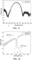
- the optical bandpass filter BPF is designed to have a narrower bandwidth (typically much narrower) than the band of the transmitted or reflected spectrum of the FBG sensor, i.e., equivalently, an FBG sensor is selected with a much greater band than that of the optical bandpass filter (as shown in figures 9-12 ). Due to this feature, the total optical power detected by the second transmission port of the filter remains practically constant in the detection range of the physical magnitude measured by the FBG sensor.
- the tuning of the optical bandpass filter BPF is carried out during the initial setting, with the aim of opportunely positioning the resonance of the optical filter with respect to the spectrum of the FBG sensor (for example, but not necessarily, in the almost linear zone of the response of the FBG sensor, which will be better disclosed below).
- the optical bandpass filter BPF operates keeping the tuned wavelength constant, to filter the optical spectrum reflected or transmitted by the FBG sensor, at the determined wavelength ⁇ i.
- the tunable optical bandpass filter BPF comprises a third input port 3, different from the aforesaid first extraction port 1 and second transmission port 2.
- the conveying step comprises conveying the optical spectrum transmitted OT or reflected OR by the at least one optical fiber sensor of the Fiber Bragg Grating type FBG to said third input port 3 of the tunable optical bandpass filter BPF.
- the method uses, as an optical bandpass filter, an optical micro-ring resonator filter (i.e. "Micro-Ring Resonator MRR”), which will be disclosed in further detail in the following description of the system according to the invention.
- an optical micro-ring resonator filter i.e. "Micro-Ring Resonator MRR”
- the optical micro-ring resonator filter is of the single-ring type, and comprises one optical ring 8.
- the optical micro-ring resonator filter is of the double-ring type, and comprises two optical rings (as shown, for example, in the scientific article " Low-Power-Consumption Integrated Tunable Filters for WDM Switching Applications in Silicon Photonics” - Manganelli et al. - IEEE Photonics Technology Letters, Vol. 30, No. 18, September 15, 2018 ).
- the method uses, as the first opto-electronic receiver PD1 and the second opto-electronic receiver PDT, a first and a second photodiode, respectively, shown in further detail in the following description of the system according to the invention.
- the aforesaid tuning step comprises tuning the optical bandpass filter BPF at a constant operating wavelength ⁇ i positioned on a linear or almost linear zone of the nominal reflection or transmission spectrum of the fiber Bragg grating of the optical fiber sensor FBG, in such a way that a shift or variation in the wavelength ⁇ of the reflection or transmission spectrum of such an optical fiber sensor of the Fiber Bragg Grating type FBG corresponds to a linear or almost linear variation in the power or intensity of the first optical signal.
- This situation is shown in figures 9-12 .
- the method includes interrogating at least one optical fiber sensor of the Fiber Bragg Grating type having a reflection spectrum with a linear shape, for example, chirped Fiber Bragg Grating.
- the method includes interrogating only one optical fiber sensor of the Fiber Bragg Grating type FBG, operating on the reflected spectrum OR of the FBG sensor.
- the method provides interrogating only one optical fiber sensor of the Fiber Bragg Grating type FBG, operating on the transmitted spectrum OT of the FBG sensor.
- the method includes interrogating a plurality of optical fiber sensors of the Fiber Bragg Grating type FBG1-FBGn in cascade, each characterized by a respective nominal operating wavelength ⁇ 1- ⁇ n.
- the conveying step comprises conveying the entire optical spectrum transmitted OT or reflected OR by the cascade of optical fiber sensors of the Fiber Bragg Grating FBG1-FBGn type to a cascade of tunable optical bandpass filters BPF1-BPFn; and the tuning step comprises tuning each of the optical bandpass filters BPF1-BPFn around a respective wavelength ⁇ 1- ⁇ n corresponding to a respective one of the nominal operating wavelengths of the optical fiber sensors of the Fiber Bragg Grating type FBG1-FBGn.
- the step of detecting at least one first optical signal L1 comprises detecting a plurality of first optical signals L11-L1n exiting the first extraction port of each of the optical bandpass filters BPF1-BPFn, each at the respective operating wavelength ⁇ 1- ⁇ n, which is kept constant; and the converting step comprises converting the plurality of first optical signals L11-L1n into a respective plurality of first electrical signals E11-E1n, by means of a plurality of first opto-electronic receivers PD1-PDn (for example, comprising first photodiodes).
- the step of detecting a second optical signal L2 comprises detecting an optical signal exiting the second transmission port 2 of the last optical bandpass filter (BPFn) of the cascade of optical bandpass filters; and the converting step comprises converting the aforesaid second optical signal L2 into a respective second electrical signal E2, by means of a second opto-electronic receiver PDT.
- BPFn optical bandpass filter
- the determining step comprises determining the wavelength shift ⁇ i, with respect to the nominal operating wavelength, of each of the spectra reflected OR or transmitted OT by each of the optical fiber sensors of the Fiber Bragg Grating type FBG1-FBGn, based on the plurality of first electrical signals detected E11-E1n, and on the second electrical signal detected E2.
- the method includes interrogating only one optical fiber sensor of the Fiber Bragg Grating type FBG on a wide range of wavelengths.
- the conveying step comprises conveying the optical spectrum transmitted OT or reflected OR by the optical fiber sensor of the Fiber Bragg Grating type FBG to a cascade of tunable optical bandpass filters BPF1-BPFn; and the tuning step comprises tuning each of the optical bandpass filters BPF1-BPFn at a respective operating wavelength ⁇ 1- ⁇ n, which is kept constant, belonging to the wide range of wavelengths of the aforesaid optical spectrum transmitted or reflected by the FBG sensor.
- the step of detecting at least one first optical signal comprises detecting a plurality of first optical signals L11-L1n exiting the first extraction port 1 of each of the optical bandpass filters BPF1-BPFn; and the step of converting the at least one first optical signal comprises converting the plurality of first optical signals L1 1-L1n into a respective plurality of first electrical signals E11-E1n, by means of a plurality of first opto-electronic receivers PD1-PDn (for example, comprising first photodiodes).
- the step of detecting a second optical signal L2 comprises detecting an optical signal exiting the second transmission port 2 of the last optical bandpass filter BPFn of the cascade of optical bandpass filters, and the step of converting the second optical signal L2 comprises converting this second optical signal into a respective second electrical signal E2, by means of a second opto-electronic receiver PDT.
- the determining step comprises determining the peak of the reflection or transmission wavelength of the FBG sensor, within said wide range of wavelengths, based on the plurality of first electrical signals detected E11-E1n, and on the second electrical signal detected E2.
- each of the first electrical signals E1i (belonging to the group E11-E1n) is representative of an electrical voltage, proportional to the optical power incident on a respective opto-electronic receiver Pdi (belonging to the group of opto-electronic receivers PD1-PDn), and therefore, it is correlated (for example, proportional) to the respective wavelength shift ⁇ i of the spectrum reflected or transmitted by the respective optical fiber sensor FBGi (belonging to the group of sensors FBG1-FBGn).
- the method further includes, before the conveying step, the step of splitting the total optical power, by means of an optical splitter D, and sending a part thereof to a third opto-electronic receiver PDD, to obtain a third electrical signal E3, adapted to support a further compensation.
- the optical bandpass filter for example the micro-ring resonator, allows to filter a part of the signal reflected (or transmitted) by the FBG sensor at the resonance frequency of the resonant ring on the extraction port 1 ("drop port") of the optical micro-ring filter; and also to obtain a transmitted spectrum (corresponding to the spectrum of the FBG sensor without the aforesaid filtered part) on the transmission port 2 ("through port") of the optical micro-ring filter.
- the method is based on optical bandpass filters with two complementary ports, and on two photo-detectors, one for each of such complementary ports.
- one or more two-ports micro-ring resonators are used, for querying a single FBG sensor or a plurality of FBG sensors, with two photo-detectors, integrated for each micro-ring resonator, connected to the two "drop" and "through” output ports of the micro-ring resonator.
- Such a system comprises at least one optical fiber sensor of the Fiber Bragg Grating FBG type, a broadband optical radiation source S, at least one tunable optical bandpass filter BPF, a first opto-electronic receiver PD1, a second opto-electronic receiver PDT and electronic processing means 4.
- the broadband optical radiation source S is configured to light the at least one optical fiber sensor of the Fiber Bragg Grating type FBG with a broadband excitation optical radiation OA.
- the broadband optical radiation source S can comprise a super-luminescent LED (SLED), or the spontaneous amplified emission (AE) of an erbium-doped optical amplifier (EDFA).
- SLED super-luminescent LED
- AE spontaneous amplified emission
- EDFA erbium-doped optical amplifier
- the broadband optical radiation source S is a component external to the photonic integrated circuit PIC, in which the optical bandpass filter BPF and the first opto-electronic receiver PD1 and second opto-electronic receiver PDT are integrated.
- the broadband optical radiation source S is integrated in the photonic integrated circuit PIC, in which the optical bandpass filter BPF and the first opto-electronic receiver PD1 and second opto-electronic receiver PDT are integrated.
- appropriate integration technologies can be used, which are known per se, for example, based on semi-conductors from the group III-V and on Silicon-On-Insulator SOI technology (as shown, for example, in the scientific article " Hybrid Silicon Laser Technology: A Thermal Perspective" - M.N. Sysak et al. - IEEE Journal of Selected Topics in Quantum Electronics, Vol. 17, No. 6, Nov./Dec. 2011 ).
- the at least one tunable optical bandpass filter BPF comprises a first extraction port 1 and a second transmission port 2, which are complementary to each other, and it further comprises a third input port 3 (different from the aforesaid first extraction port 1 and second transmission port 2), which is operatively connected to the at least one optical fiber sensor of the Fiber Bragg Grating type FBG, to receive the optical spectrum transmitted OT or reflected OR by such a sensor,
- the optical bandpass filter BPF is tunable, in a range of wavelengths, at a constant operating wavelength ⁇ i, depending on the nominal operating wavelength of the fiber Bragg grating of the optical fiber sensor FBG.
- the first opto-electronic receiver PD1 is operatively connected to the first extraction port 1 of the optical bandpass filter BPF to receive a respective first optical signal L1, and it is configured to convert such a first optical signal L1 into a respective first electrical signal E1.
- the aforesaid first optical signal is a narrow-band optical filtering of the transmission OT or reflection spectrum OR of the fiber Bragg grating of the optical fiber sensor FBG at the constant operating wavelength of the optical filter.
- the second opto-electronic PDT receiver is operatively connected to the second transmission port 2 of the optical bandpass filter BPF to receive a second optical signal L2, and it is configured to convert said second optical signal L2 into a respective second electrical signal E2, representative of an optical reference power, which is substantially independent of the filtering wavelength, and having a dependence on the power of the broadband excitation optical radiation, and on the losses of the overall optical path, equal to the dependence undergone by the first optical signal.
- the electronic processing means 4 are operatively connected to the aforesaid first opto-electronic receiver PD1 and second opto-electronic receiver PDT, and they are configured to determine a wavelength shift ⁇ , with respect to the nominal operating wavelength, of the spectrum reflected OR or transmitted OT by the Bragg grating of the optical fiber sensor FBG, based on the first electrical signal detected E1, deriving from the first optical signal L1, and based on the second electrical signal E2, representative of the reference optical power detected, deriving from the second optical signal L2, so that the detection of the first electrical signal is compensated for with respect to variations in power of broadband excitation optical radiation and variations in loss on the optical path.
- the aforesaid wavelength shift ⁇ of the spectrum reflected or transmitted by the determined Bragg grating is representative of the physical magnitude measured by the optical fiber sensor FBG.
- the aforesaid optical bandpass filter BPF and the aforesaid first opto-electronic receiver PD1 and second opto-electronic receiver PDT are integrated in a photonic integrated photonic circuit ("Photonic Integrated Circuit" - PIC).
- such a first electrical signal E1 can be an electric current or an electrical voltage.
- the first electrical signal E1 is representative of (or corresponds to) an electrical voltage, proportional to the optical power incident on the opto-electronic receiver, and therefore it is correlated (for example, proportional) to the aforesaid wavelength shift ⁇ of the spectrum reflected or transmitted by the optical fiber sensor FBG.
- the aforesaid optical bandpass filter BPF is an optical micro-ring resonator filter (i.e. "Micro-Ring Resonator MRR").
- the optical micro-ring resonator filter is of the single-ring type, and comprises a single ring 8, or the optical micro-ring resonator filter is of the double-ring type, and comprises two optical rings.
- the ring resonator is a structure, in which the optical wave guide or conductor is closed in a loop configuration: when the light, at the particular resonance wavelength, passes through the ring with constructive interference, the intensity of the light grows inside the ring and the light (at the resonance wavelength) can be extracted and seen from the extraction /monitoring port of the ring resonator filter.
- the two spectra exiting the extraction 1 and transmission 2 ports of the micro-ring resonator filter BPF are complementary to each other, and the resonator rings acts as a bandpass filter for the extraction port 1.
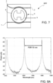
- the resonance wavelength of the micro-ring resonator depends on the refractive index of the material and on the geometry of the device (waveguide dimension and ring diameter); the resonant wavelength can be varied, in a controlled manner, i.e., tuned, by means of a small modification of the refractive index of the optical guide, for example, through a thermal tuning based on a local micro-heater 9 (shown, for example, in figure 7 ).
- the extraction port 1 of the optical bandpass filter BPF transforms a shift ⁇ of the operating wavelength of the FBG sensor, due to the variation of the physical parameter to be measured, into a power variation detected by the integrated photo-detector or photodiode (variation of optical power upstream of the photodiode, and corresponding variation of electrical voltage downstream of the photodiode), while the transmission port 2 of the optical bandpass filter BPF provides a retro-reflected signal having a complementary spectrum with respect to the signal exiting the extraction port 1.
- the power at the output of the transmission port 2 is almost equal to the total power of the spectrum of the FBG sensor (in other words, the portion filtered and extracted at the extraction port 1 is negligible with respect to the total power).
- a differential detection which considers the double detection at both ports (extraction and transmission) of the optical bandpass filter, provides a measurement which is immune from spurious fiber losses and power fluctuations of the laser or other optical source.
- the optical micro-ring resonator 6 can be tuned at a wavelength by means of thermo-optical effect in Silicon (in which the micro-ring resonator is integrated). This means that the transfer function of the wavelength filter (i.e., the spectrum of the "drop" port depicted in figure 8A ) can be moved by applying a command signal in voltage or electric power.
- the application of a signal in the order of some Volts, with a few dozen mW thermal power dissipated by, on a micro-ring resonator filter having a radius of a dozen ⁇ m, can cause a spectrum shift of between 5 and 8 nm.
- the spectrum of the extraction ports of the micro-ring resonator filter is shown in the range of wavelengths between 1540 nm and 1565 nm. Being a resonance filter, the spectrum is periodic, with a determined Free Spectral Range (FSR), which, in the example in figure 8 , is equal to 10 nm.
- FSR Free Spectral Range
- the optical micro-ring resonator filter is designed in such a way that the FSR parameter is greater than the maximum shift ⁇ of the operating wavelength of the FBG sensor.
- the spectrum of the transmission port of the micro-ring resonator filter is shown in the same range of wavelengths between 1540 nm and 1565 nm.
- the spectrum is periodic, with a determined Free Spectral Range (FSR), which, in the example in figure 8B , is also equal to 10 nm.
- FSR Free Spectral Range
- Figure 9 shown an example of a reflected spectrum of an optical fiber sensor FBG and the spectrum of the transmission port 2 of the optical bandpass filter BPF.
- Figures 10 and 11 illustrate the spectra exiting the first extraction port 1 and the second transmission port 2 of the optical filter respectively, when, the optical spectrum reflected by the optical fiber sensor FBG is injected at the input.
- Figure 12 shows an enlarged detail of the spectra in figures 10 and 11 , around the wavelength ⁇ i.
- the micro-ring resonator is a compact and flexible device, and it can be integrated in a photonic integrated circuit PIC on different technological platforms, such as photonics on silicon (Si) or InP; furthermore, integrated photo-detectors, capable of providing quick broadband responses, can be obtained on the same platform.
- the optical circulator 5 and/or the broadband optical radiation source S can also be integrated on the same platform.
- an FBG sensor is a highly sensitive and versatile optical device for measuring various physical parameters, including, for example, strain and temperature.
- an FBG sensor is obtained by means of a spatially periodic modulation of the refractive index inscribed in the "core" of the optical fiber.
- FBG sensors are "passive" sensors, meaning that they do not need to be powered, but they are activated by lighting, i.e., by sending an optical activation radiation, at an appropriate wavelength (e.g., the Bragg wavelength), in the optical fiber section, in which the grating in the sensor is obtained.
- the FBG sensor either reflects or transmits an optical (i.e., photonic) signal which depends not only on the incident radiation, but also on the strain and temperature conditions to which the grating itself is subjected.
- an optical signal i.e., photonic
- such a photonic signal can be an optical signal (or optical spectrum) which is transmitted or an optical signal (or optical spectrum) which is reflected.
- the at least one optical fiber sensor of the Fiber Bragg Grating type FBG is an optical fiber sensor of the Fiber Bragg Grating type having a reflection spectrum with a linear shape.
- This embodiment exploits the highly linear shape of the response of the FBG sensor as a linear reflective filter, to guarantee elevated dynamic interrogation performance and a wide dynamic range for strain or temperature measurements.
- the use of the FBG sensor with a linear response also simplifies the calibration of the interrogator.
- the aforesaid first opto-electronic receiver PD1 comprises (or consists of) a first photodiode
- the aforesaid second opto-electronic receiver PDT comprises (or consists of) a second photodiode.
- the aforesaid first and second photodiode are, for example, semi-conductor photodiodes, of the type known per se, designed to detect and convert optical signals, at the wavelengths considered, into electrical signals.
- the system 10 is configured to interrogate only one optical fiber sensor of the Fiber Bragg Grating type FBG, acting on the reflected spectrum OR of the FBG sensor.
- the system 10 is configured to interrogate only one optical fiber sensor of the Fiber Bragg Grating type FBG, acting on the transmitted spectrum OT of the FBG sensor.
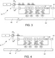
- the system comprises a plurality of optical fiber sensors of the Fiber Bragg Grating FBG1-FBGn type, in cascade, each characterized by a respective nominal operating wavelength ⁇ 1- ⁇ n, and a respective plurality of tunable optical bandpass filters BPF1-BPFn in cascade (i.e., in a configuration, in which the transmission port of a filter is connected to the input port of the filter placed just afterwards in the cascade), each tunable around a respective wavelength corresponding to a respective one of the nominal operating wavelengths ⁇ 1- ⁇ n of the optical fiber sensors of the Fiber Bragg Grating FBG1-FBGn type.
- the system 10 further comprises a plurality of opto-electronic receivers (PD1-PDn), configured to receive a plurality of first optical signals L11-L1n and convert such a plurality of first optical signals L11-L1n into a respective plurality of first electrical signals E11-E1n; and a second opto-electronic receiver PDT, operatively connected to the second transmission port 2 of the last optical bandpass filter BPF of the cascade of optical bandpass filters to receive the second optical signal L2 and convert it into a respective second electrical signal E2.
- PD1-PDn opto-electronic receivers
- the electronic processing means 4 are configured to determine the wavelength shift ⁇ , with respect to the nominal operating wavelength, of each of the spectra reflected or transmitted by each of the optical fiber sensors of the Fiber Bragg Grating type FBG1-FBGn, based on the plurality of first electrical signals detected E11-E1n, and the second electrical signal E2.
- the i-th BPF ring resonator filter is tuned at a certain wavelength ⁇ i for interrogating the i-th FBGi sensor; each single BPFi bandpass filter is tuned at a different wavelength ⁇ i and the combined acquisition of the signals by the N photo-detectors provides the measurement of the wavelength peaks of each of the different N FBG sensors.
- the system 10 comprises at least one optical fiber sensor of the Fiber Bragg Grating FBG type, operating and suitable to be interrogated along a wide range of wavelengths.
- the system 10 further comprises a plurality of tunable optical bandpass filters BPF1-BPFn in cascade, each being tunable at a respective operating wavelength ⁇ 1- ⁇ n, which is kept constant, belonging to the wide range of wavelengths of the aforesaid optical spectrum transmitted or reflected by the sensor.
- the system further comprises a plurality of first opto-electronic receivers PD1-PDn, configured to receive the plurality of first optical signals L11-L1n into a respective plurality of first electrical signals E11-E1n; and a second opto-electronic receiver PDT, operatively connected to the second transmission port 2 of the last optical bandpass filter BPF of the cascade of optical bandpass filters, to receive the second optical signal L2 and convert it into a respective second electrical signal E2.
- the electronic processing means 4 are configured to determine the peak of the reflection or transmission wavelength of the FBG sensor, in the aforesaid wide range of wavelengths, based on the plurality of first electrical signals detected E11-E1n, and on the second electrical signal detected E2.
- a single FBG sensor can be queried in the case where it is experiencing a great variation in the wavelength peak, due to extreme environmental conditions (e.g., thermal excursions).
- the combined acquisition by the N photo-detectors at the N extraction ports of the ring resonators provides the measurement of the peak wavelengths along a wide range of wavelength variations due, for example, to great changes in temperature or strain.
- a CWDM (Coarse WDM) de-multiplexer is used to feed the different optical filters (instead of arranging them in cascade), to reduce losses on the optical path, advantageously.
- the i-th channel of the CWDM de-multiplexer can be used to interrogate the i-th optical fiber sensor FBGi, the Bragg wavelength ⁇ i of which is variable within the optical band of the corresponding i-th channel.
- each of the first electrical signals E1i (belonging to the group E11-E1n) is representative of an electrical voltage, proportional to the optical power incident on a respective opto-electronic receiver Pdi (belonging to the group of opto-electronic receivers PD1-PDn), and therefore, it is correlated (for example, proportional) to the respective wavelength shift ⁇ i of the spectrum reflected or transmitted by the respective optical fiber sensor FBGi (belonging to the group of sensors FBG1-FBGn).
- each of such optical bandpass filters is used as a fixed filter, and not as a tunable filter (a tuning is carried out only during the initial setting, but not during the operation).
- the Free Spectral Range must be greater than the sum of the tuning excursions allowed for each of the optical bandpass filters.
- the system 10 further comprises an optical band splitter D, arranged upstream of the tunable optical filter BPF, and a third opto-electronic receiver PDD, where the optical band splitter D is configured to split the total optical power and send a part thereof to the third opto-electronic receiver PDD, and where the third opto-electronic receiver PDD is configured to obtain a third electrical signal E3, adapted to support a further compensation.
- the system 10 further comprises an optical circulator 5 having a first port connected to the broadband optical radiation source S, a second port connected to an optical fiber F containing the optical fiber sensor of the Fiber Bragg Grating type FBG, and a third port connected to the at least one optical bandpass filter BPF.
- the optical circulator 5 is configured to transmit the broadband optical radiation S, received by the first port, to the optical fiber F containing the optical fiber sensor FBG, through the second port, and it is further configured to transmit the spectrum reflected OR by the optical fiber sensor of the Fiber Bragg Grating type FBG, received by the second port, to the at least one optical bandpass filter BPF, through the third port.
- the optical circulator 5 is a component external to the photonic integrated circuit PIC, in which the optical bandpass filter BPF and the first PD1 and the second opto-electronic receiver PDT are integrated.
- the optical circulator 5 is integrated in the photonic integrated circuit PIC, in which the optical bandpass filter BPF, the first PD1 and the second opto-electronic receiver PDT are integrated.
- appropriate integration technologies known per se, can be used, for example, based on magnetooptical materials and bonding techniques on Silicon-On-Insulator SOI technological platform (as shown, for example, in the scientific article " Broadband TE Optical Isolators and Circulators in Silicon Photonics through CE: YIG Bonding" - P. Pintus et al., Journal of Lightwave Technology, Vol. 37, No. 5, March 1, 2019 ).
- each sensor of the at least one optical fiber sensor of the Fiber Bragg Grating type FBG is configured to detect a strain acting in the position where the sensor is.
- the optical fiber sensor of the Fiber Bragg Grating FBG type is configured to act within a brake pad or be incorporated or coupled to a brake caliper, or incorporated in a washer device, adapted to be arranged between a brake caliper support and a brake caliper.
- the at least one strain detected by the at least one optical fiber sensor of the Fiber Bragg Grating FBG type is representative of a tightening force and/or braking torque acting on the brake caliper.
- the electronic processing means 4 comprise at least one electronic processor or micro-processor 40, of the type known per se, adapted to store and run software programs.
- the system 10 can comprise further electronic systems, which are known per se, such as, for example, ADC analog-digital converters, trans-impedance amplifiers 41, ASIC 42 devices for conditioning the electrical signals, and appropriate optical connections (indicated with a continuous line in figures 1-5 ) and electrical connections (indicated with a dotted line in figures 1-5 ).
- ADC analog-digital converters such as, for example, ADC analog-digital converters, trans-impedance amplifiers 41, ASIC 42 devices for conditioning the electrical signals, and appropriate optical connections (indicated with a continuous line in figures 1-5 ) and electrical connections (indicated with a dotted line in figures 1-5 ).
- the functional block 42 is intended as a block for conditioning the analog signals (i.e., adaptation of the converted and amplified signals), and the functional block 40 is a digital signal conversion and processing block 40, which provides the processed data on an appropriate interface/bus at the output.
- the functional block 40 and, at least partially, the functional block 42 can be obtained by means of a single integrated circuit, for example, of the ASIC or FPGA type.
- tables e.g., look-up tables
- the electronic processing means for example, in the conversion and processing block 40
- measurements carried out during the characterization which establish the relationship between a measured voltage value and a shift value of the peak wavelength of the FBG sensor.
- the power compensation made possible by the detection of the optical signal on the transmission port of the optical bandpass filter, it can be carried out, for example, by means of normalization of the power detected at the extraction port with respect to the power detected at the transmission port.
- the method and the system according to the invention comprise an active control of the temperature of the chip and relative electronic compensations, so as to allow the operation thereof on a wide temperature range, for example, in environments with elevated thermal excursion.
- the object of the present invention is fully achieved by the method and system disclosed above, by virtue of the functional and structural features thereof.
- the system according to the invention is a simple and compact system, in which the essential components are integrated (for example, in photonic integrated circuits in PIC technology).
- the integration can be carried out by means of silicon technology; in particular, the system according to the invention lends itself to an integration of both photonic circuits and electronic circuits in hybrid chips produced using the same process.
- the technical solution described above also allows the broadband source and/or the optical circulator to be integrated in the same integrated circuit, in which the optical filter and the photo-detectors are integrated, providing a remarkable design flexibility.
- the system and method of the present invention work by keeping the wavelength of the optical bandpass filters constant (which are only tuned in an initial setting step), which take a portion of the spectra transmitted or reflected by the FBG sensor. Since such spectra move due to effects related to the variable to be measured, the constant wavelength sampling by the micro-ring optical filter records such variations in the form of variations in detected power.
- the dynamic performance doesn't depend on the tuning times of the optical bandpass filter, but only on the speed of the photo-detection block, therefore providing a much quicker dynamic response with respect to the previously stated known solutions.
- the system and method according to the invention exploiting the simultaneous detection of the optical power both on the extraction port and on the transmission port, have improved immunity with respect to spurious losses and/or fluctuations in the optical lighting power.
- the claimed solution includes a narrow-band optical filtering of the transmission or reflection spectrum of the FBG optical fiber sensor around the operating wavelength (unlike what would be obtained by using, for example, solutions based on Fabry-Perot filters, the bandwidth of which can be compared to that of the optical signal of the FBG sensor to be queried).
- the bandwidth of the spectrum reflected by the interrogated FBG sensor is greater than the line width of the resonance spectrum of the optical filter used in the present solution (and, in particular, much greater in the implementation option which includes using micro-ring optical resonator filters), offers various advantages, including: the possibility of disturbing the spectrum exiting the transmission port of the filter as little as possible; the possibility of selecting the "finesse" of the resonance spectrum of the optical filter as an important design parameter to improve the performance of the interrogator in terms of spectral dynamic resolution.
- the band depends on the reception band of the photodiodes used, i.e., on components capable of acting on a very wide band (for example, integrated photodiodes of the PIN type are known, which use, as absorption material, Germanium with bands ranging from MHz even up to 40 GHz. For the applications considered herein, it is necessary to observe phenomena with bands no larger than hundreds of KHz, which are easily guaranteed by the system according to the invention).
Landscapes
- Physics & Mathematics (AREA)
- General Physics & Mathematics (AREA)
- Optical Transform (AREA)
- Optical Integrated Circuits (AREA)
- Optical Modulation, Optical Deflection, Nonlinear Optics, Optical Demodulation, Optical Logic Elements (AREA)
- Length Measuring Devices By Optical Means (AREA)
Description
- . The invention relates, in general, to a method and system for measuring physical parameters by means of the use of optical fiber sensors of the Fiber Bragg Grating type.
- . More specifically, the present invention relates to a method and system for interrogating an optical fiber sensor of the Fiber Bragg Grating type, using a tunable optical bandpass filter.
- . Optical fiber sensors of the Fiber Bragg Grating type (FBG sensors) are becoming more and more frequently used for measuring physical magnitudes, such as strain or temperature, by virtue of the properties of simplicity and precision. Such sensors are passive, meaning that they need to be lit by an optical radiation and the spectrum reflected or transmitted thereby must be analyzed in order to obtain the measurement of the desired physical magnitude.
- . In fact, since the variation in the detected physical magnitudes causes a shift of the spectrum and/or of the reflected peak wavelength of the FBG sensor, in the most common known solutions, it is necessary to scan a certain range of wavelengths to determine the result.
- . Typically, in known solutions, this can be done in two alternative ways: lighting by means of an optical source that is wavelength-tunable (for example, tunable lasers), and broadband reception; or, broadband lighting and reception by means of an electrically or optically tunable receiver (for example, Arrayed WaveGuide Grating, AWG, or spectrometer).
- . In other words, either at the transmission or at the reception side there must be a tunable device, which for each interrogation/query of the FBG sensor, must implement a scan on a wavelength, by sequentially optically or electrically tuning on a certain number of operating wavelengths belonging to a certain range.
- . This results in notable drawbacks, related to both the complexity of the devices requested (for example, lasers tunable on transmission, or spectrometers on reception), and problems of slow responses or limited dynamics, due to the timeframe of the sequential tuning on a range of wavelengths, which can also be large.
- . One possible evolution, at the reception side, can derive from the use of tunable optical filters (for example, micro-ring resonator filters, e.g., in the variants comprising one or two rings for each single filter). However, such solutions also suffer from relatively slow dynamics, since the operation of such systems includes tuning the tunable optical filter by means of a continuous scan, carried out periodically, of the spectrum of the FBG sensor, around the central wavelength, to identify the peak of the spectrum of the FBG sensor. Thus, the dynamic performance of such a device depends on the scanning speed of the resonance wavelength of the micro-ring, which is relatively slow. The document
WO2008/028138 A2 discloses a method for interrogating at least one optical fibre sensor of the Fibre Bragg Grating type according to the state of the art. - . Another problem emerging in this solution (as in the other previously mentioned known solutions) derives from the effects of the spurious power variations due to laser emission power variations and spurious variable losses of the optical path covered by the optical beams.
- . In the light of the above, the need is strongly felt for systems and methods for interrogating FBG sensors, obtained in integrated optics, which are able to mitigate the aforesaid technical problems, and satisfy the following criteria: (i) a compact and simple structure and compact and simple use; (ii) improved dynamic performance, with quicker responses; (iii) greater immunity to spurious losses and/or fluctuations of the optical lighting power (iv) low cost; (v) robustness to hostile environments.
- . Such needs are felt for methods of interrogating FBG sensors used in a wide range of applications, including the important field of application for measurements carried out in pads and calipers of a braking system.
- . As already noted, the above needs are not fully met by the solutions currently offered by the prior art.
- . It is an object of the present invention to provide a method for interrogating an optical fiber sensor of the Fiber Bragg Grating type, using a tunable optical bandpass filter, which allows to at least partially overcome the above drawbacks with reference to the prior art, and to meet the above needs particularly felt in the technical field in hand.
- . These and other objects are achieved by a method for interrogating an optical fiber sensor of the Fiber Bragg Grating type, using a tunable optical bandpass filter according to
claim 1. - . Some advantageous embodiments of such a method are the subject of the dependent claims 2-6.
- . It is also the object of the present invention to provide a corresponding system for interrogating an optical fiber sensor of the Fiber Bragg Grating type, using a tunable optical bandpass filter.
- . This object is achieved by a system according to claim 7.
- . Some advantageous embodiments of such a system are the subject of the dependent claims 8-15.
- . Further features and advantages of the method and system according to the invention will become apparent from the description below of preferred embodiments thereof, provided by way of non-limiting explanation, with reference to the accompanying drawings, in which:
-
figures 1-5 show, by means of functional block diagrams, respective different embodiments of a system for interrogating an optical fiber sensor of the Fiber Bragg Grating type according to the present invention; -
figure 6 shows a functional diagram of an optical bandpass filter comprised in an embodiment of the system according to the invention, and it further depicts an example of optical spectra entering the optical filter, exiting a first extraction port of the optical filter and exiting a second transmission port of the optical filter; -
figure 7 shows a structural diagram of an optical micro-ring resonator bandpass filter, comprised in one embodiment of the system; -
figures 8A and8B depict the spectra exiting the first extraction port and the second transmission port of the optical filter respectively, when a broadband optical signal is injected at the input; -
figure 9 shows an example of a reflected spectrum of an optical fiber sensor FBG and the narrow-band sampling carried out by the optical bandpass filter infigures 7 and8 ; -
figures 10 and11 depict the spectra exiting the first extraction port and the second transmission port of the optical filter, respectively, when the optical spectrum reflected by the optical fiber sensor FBG is injected at the input; -
figure 12 shows an enlarged detail of the spectra infigures 10 and11 ; -
figures 13 and14 show two further respective embodiments of a system for interrogating an optical fiber sensor of the Fiber Bragg Grating type according to the present invention by means of functional block diagrams. - . A method for interrogating at least one optical fiber sensor of the Fiber Bragg Grating type FBG (also referred to as "FBG sensor", for brevity, below) is now described with reference to
figures 1-14 . - . The method comprises, first of all, the steps of lighting the aforesaid at least one optical fiber sensor of the Fiber Bragg Grating type FBG with a broadband excitation optical radiation OA, and conveying the optical spectrum transmitted OT or the optical spectrum reflected OR by the at least one optical fiber sensor of the Fiber Bragg Grating type FBG to at least one tunable optical bandpass filter BPF, having a
first extraction port 1 and asecond transmission port 2, which are complementary to each other. - . The method also includes tuning the optical bandpass filter BPF at a constant operating wavelength λi, depending on the nominal operating wavelength of the fiber Bragg grating of the optical fiber sensor FBG.
- . The method then comprises the step of detecting a respective first optical signal L1 exiting the
first extraction port 1 of the optical bandpass filter. Such a first optical signal is a narrow-band optical filtering of the transmission spectrum OT or reflection spectrum OR of the fiber Bragg grating of the optical fiber sensor FBG around the constant operating wavelength λi of the optical bandpass filter BPF. - . The method then provides converting, by means of a first opto-electronic receiver PD1, the aforesaid first optical signal L1 into a respective first electrical signal E1, representative of a wavelength shift Δλ, with respect to the nominal operating wavelength, of the spectrum reflected or transmitted by the Bragg grating of the optical fiber sensor FBG.
- . In different implementation options, this first electrical signal E1 can be an electric current or an electrical voltage.
- . In a preferred implementation option, the first electrical signal E1 is representative of (or corresponding to) an electrical voltage, proportional to the optical power incident on the first opto-electronic receiver PD1, and therefore, it is correlated (for example, proportional) to the aforesaid wavelength shift Δλ of the spectrum reflected or transmitted by the optical fiber sensor FBG.
- . The method then comprises the steps of detecting a second optical signal L2, exiting the
second transmission port 2 of the optical bandpass filter BPF, spectrally complementary to the first optical signal L1; and converting such a second optical signal L2, by means of a second opto-electronic receiver PDT, into a respective second electrical signal E2, representative of an optical reference power, which is substantially independent of the filtering wavelength, and having a dependence on the power of the broadband excitation optical radiation, and on the losses of the overall optical path, equal to the dependence undergone by the first optical signal. - . In different implementation options, such a second electrical signal E2 can be an electric current or an electrical voltage.
- . In a preferred implementation option, the second electrical signal E2 is representative of (or corresponding to) an electrical voltage, proportional to the optical power incident on the second opto-electronic receiver PDT.
- . Finally, the method provides determining the wavelength shift Δλ, with respect to the nominal operating wavelength, of the spectrum reflected or transmitted by the Bragg grating of the optical fiber sensor FBG, based on the first electrical signal detected E1, deriving from the optical signal L1 exiting the
first extraction port 1 of the optical bandpass filter BPF, and based on the second electrical signal E2, representative of the optical power of reference detected, deriving from the second optical signal L2 exiting thesecond transmission port 2 of the optical bandpass filter BPF, so that the detection of the first electrical signal is compensated for with respect to variations in power of broadband excitation optical radiation and variations in loss on the optical path. - . The aforesaid wavelength shift Δλ of the spectrum reflected OR or transmitted OT by the determined Bragg grating is representative of the physical magnitude measured by the optical fiber sensor FBG.
- . The aforesaid optical bandpass filter BPF and the aforesaid first opto-electronic receiver PD1 and second opto-electronic receiver PDT are integrated in a photonic integrated circuit (Photonic Integrated Circuit" - PIC).
- . In typical operating conditions, the optical bandpass filter BPF is designed to have a narrower bandwidth (typically much narrower) than the band of the transmitted or reflected spectrum of the FBG sensor, i.e., equivalently, an FBG sensor is selected with a much greater band than that of the optical bandpass filter (as shown in
figures 9-12 ). Due to this feature, the total optical power detected by the second transmission port of the filter remains practically constant in the detection range of the physical magnitude measured by the FBG sensor. - . The tuning of the optical bandpass filter BPF is carried out during the initial setting, with the aim of opportunely positioning the resonance of the optical filter with respect to the spectrum of the FBG sensor (for example, but not necessarily, in the almost linear zone of the response of the FBG sensor, which will be better disclosed below).
- . After tuning, the optical bandpass filter BPF operates keeping the tuned wavelength constant, to filter the optical spectrum reflected or transmitted by the FBG sensor, at the determined wavelength λi. The variations, i.e., the shifts Δλ, of the wavelength of the peak and of the entire optical spectrum reflected or transmitted by the FBG sensor, due to the physical phenomena that are desired to be measured, cause the part of the optical spectrum filtered by the optical bandpass filter to undergo consequent variations, and ultimately determine optical power variations at the output of the optical bandpass filter, correlated, in a known manner, to the wavelength shift/variation of the spectrum of the FBG sensor.
- . According to an embodiment of the method, the tunable optical bandpass filter BPF comprises a
third input port 3, different from the aforesaidfirst extraction port 1 andsecond transmission port 2. In this case, the conveying step comprises conveying the optical spectrum transmitted OT or reflected OR by the at least one optical fiber sensor of the Fiber Bragg Grating type FBG to saidthird input port 3 of the tunable optical bandpass filter BPF. - . According to one embodiment, the method uses, as an optical bandpass filter, an optical micro-ring resonator filter (i.e. "Micro-Ring Resonator MRR"), which will be disclosed in further detail in the following description of the system according to the invention.
- . According to an implementation option, illustrated below, the optical micro-ring resonator filter is of the single-ring type, and comprises one
optical ring 8. - . According to another implementation option, the optical micro-ring resonator filter is of the double-ring type, and comprises two optical rings (as shown, for example, in the scientific article " Low-Power-Consumption Integrated Tunable Filters for WDM Switching Applications in Silicon Photonics" - Manganelli et al. - IEEE Photonics Technology Letters, Vol. 30, No. 18, September 15, 2018).
- . According to one embodiment, the method uses, as the first opto-electronic receiver PD1 and the second opto-electronic receiver PDT, a first and a second photodiode, respectively, shown in further detail in the following description of the system according to the invention.
- . According to a preferred embodiment, the aforesaid tuning step comprises tuning the optical bandpass filter BPF at a constant operating wavelength λi positioned on a linear or almost linear zone of the nominal reflection or transmission spectrum of the fiber Bragg grating of the optical fiber sensor FBG, in such a way that a shift or variation in the wavelength Δλ of the reflection or transmission spectrum of such an optical fiber sensor of the Fiber Bragg Grating type FBG corresponds to a linear or almost linear variation in the power or intensity of the first optical signal. This situation is shown in
figures 9-12 . - . According to an implementation option, the method includes interrogating at least one optical fiber sensor of the Fiber Bragg Grating type having a reflection spectrum with a linear shape, for example, chirped Fiber Bragg Grating.
- . According to an embodiment, shown in
figure 1 , the method includes interrogating only one optical fiber sensor of the Fiber Bragg Grating type FBG, operating on the reflected spectrum OR of the FBG sensor. - . According to another embodiment, shown in
figure 2 , the method provides interrogating only one optical fiber sensor of the Fiber Bragg Grating type FBG, operating on the transmitted spectrum OT of the FBG sensor. - . According to a further embodiment (shown in
figure 3 ), the method includes interrogating a plurality of optical fiber sensors of the Fiber Bragg Grating type FBG1-FBGn in cascade, each characterized by a respective nominal operating wavelength λ1-λn. - . In this case, the conveying step comprises conveying the entire optical spectrum transmitted OT or reflected OR by the cascade of optical fiber sensors of the Fiber Bragg Grating FBG1-FBGn type to a cascade of tunable optical bandpass filters BPF1-BPFn; and the tuning step comprises tuning each of the optical bandpass filters BPF1-BPFn around a respective wavelength λ1-λn corresponding to a respective one of the nominal operating wavelengths of the optical fiber sensors of the Fiber Bragg Grating type FBG1-FBGn.
- . The step of detecting at least one first optical signal L1 comprises detecting a plurality of first optical signals L11-L1n exiting the first extraction port of each of the optical bandpass filters BPF1-BPFn, each at the respective operating wavelength λ1-λn, which is kept constant; and the converting step comprises converting the plurality of first optical signals L11-L1n into a respective plurality of first electrical signals E11-E1n, by means of a plurality of first opto-electronic receivers PD1-PDn (for example, comprising first photodiodes).
- . The step of detecting a second optical signal L2 comprises detecting an optical signal exiting the
second transmission port 2 of the last optical bandpass filter (BPFn) of the cascade of optical bandpass filters; and the converting step comprises converting the aforesaid second optical signal L2 into a respective second electrical signal E2, by means of a second opto-electronic receiver PDT. - . The determining step comprises determining the wavelength shift Δλi, with respect to the nominal operating wavelength, of each of the spectra reflected OR or transmitted OT by each of the optical fiber sensors of the Fiber Bragg Grating type FBG1-FBGn, based on the plurality of first electrical signals detected E11-E1n, and on the second electrical signal detected E2.
- . According to another embodiment (shown in
figure 4 ), the method includes interrogating only one optical fiber sensor of the Fiber Bragg Grating type FBG on a wide range of wavelengths. - . In this case, the conveying step comprises conveying the optical spectrum transmitted OT or reflected OR by the optical fiber sensor of the Fiber Bragg Grating type FBG to a cascade of tunable optical bandpass filters BPF1-BPFn; and the tuning step comprises tuning each of the optical bandpass filters BPF1-BPFn at a respective operating wavelength λ1-λn, which is kept constant, belonging to the wide range of wavelengths of the aforesaid optical spectrum transmitted or reflected by the FBG sensor.
- . The step of detecting at least one first optical signal comprises detecting a plurality of first optical signals L11-L1n exiting the
first extraction port 1 of each of the optical bandpass filters BPF1-BPFn; and the step of converting the at least one first optical signal comprises converting the plurality of first optical signals L1 1-L1n into a respective plurality of first electrical signals E11-E1n, by means of a plurality of first opto-electronic receivers PD1-PDn (for example, comprising first photodiodes). - . The step of detecting a second optical signal L2 comprises detecting an optical signal exiting the
second transmission port 2 of the last optical bandpass filter BPFn of the cascade of optical bandpass filters, and the step of converting the second optical signal L2 comprises converting this second optical signal into a respective second electrical signal E2, by means of a second opto-electronic receiver PDT. - . The determining step comprises determining the peak of the reflection or transmission wavelength of the FBG sensor, within said wide range of wavelengths, based on the plurality of first electrical signals detected E11-E1n, and on the second electrical signal detected E2.
- . According to a preferred implementation option, each of the first electrical signals E1i (belonging to the group E11-E1n) is representative of an electrical voltage, proportional to the optical power incident on a respective opto-electronic receiver Pdi (belonging to the group of opto-electronic receivers PD1-PDn), and therefore, it is correlated (for example, proportional) to the respective wavelength shift Δλi of the spectrum reflected or transmitted by the respective optical fiber sensor FBGi (belonging to the group of sensors FBG1-FBGn).
- . According to a further embodiment (shown in
figure 5 ) the method further includes, before the conveying step, the step of splitting the total optical power, by means of an optical splitter D, and sending a part thereof to a third opto-electronic receiver PDD, to obtain a third electrical signal E3, adapted to support a further compensation. - . As noted above (and as depicted in
figure 6 ) the optical bandpass filter, for example the micro-ring resonator, allows to filter a part of the signal reflected (or transmitted) by the FBG sensor at the resonance frequency of the resonant ring on the extraction port 1 ("drop port") of the optical micro-ring filter; and also to obtain a transmitted spectrum (corresponding to the spectrum of the FBG sensor without the aforesaid filtered part) on the transmission port 2 ("through port") of the optical micro-ring filter. - . In summary, as previously disclosed, the method is based on optical bandpass filters with two complementary ports, and on two photo-detectors, one for each of such complementary ports.
- . In particular, in one embodiment, one or more two-ports micro-ring resonators are used, for querying a single FBG sensor or a plurality of FBG sensors, with two photo-detectors, integrated for each micro-ring resonator, connected to the two "drop" and "through" output ports of the micro-ring resonator.
- . Again with reference to
figures 1-14 , asystem 10 is now described for interrogating at least one optical fiber sensor of the Fiber Bragg Grating FBG type. - . Such a system comprises at least one optical fiber sensor of the Fiber Bragg Grating FBG type, a broadband optical radiation source S, at least one tunable optical bandpass filter BPF, a first opto-electronic receiver PD1, a second opto-electronic receiver PDT and electronic processing means 4.
- . The broadband optical radiation source S is configured to light the at least one optical fiber sensor of the Fiber Bragg Grating type FBG with a broadband excitation optical radiation OA.
- . According to different possible embodiments of the system, the broadband optical radiation source S can comprise a super-luminescent LED (SLED), or the spontaneous amplified emission (AE) of an erbium-doped optical amplifier (EDFA).
- . According to an implementation option, the broadband optical radiation source S is a component external to the photonic integrated circuit PIC, in which the optical bandpass filter BPF and the first opto-electronic receiver PD1 and second opto-electronic receiver PDT are integrated.
- . According to another implementation option (shown, for example, in
figure 13 ), the broadband optical radiation source S is integrated in the photonic integrated circuit PIC, in which the optical bandpass filter BPF and the first opto-electronic receiver PD1 and second opto-electronic receiver PDT are integrated. To this end, appropriate integration technologies can be used, which are known per se, for example, based on semi-conductors from the group III-V and on Silicon-On-Insulator SOI technology (as shown, for example, in the scientific article "Hybrid Silicon Laser Technology: A Thermal Perspective" - M.N. Sysak et al. - IEEE Journal of Selected Topics in Quantum Electronics, Vol. 17, No. 6, Nov./Dec. 2011). - . The at least one tunable optical bandpass filter BPF comprises a
first extraction port 1 and asecond transmission port 2, which are complementary to each other, and it further comprises a third input port 3 (different from the aforesaidfirst extraction port 1 and second transmission port 2), which is operatively connected to the at least one optical fiber sensor of the Fiber Bragg Grating type FBG, to receive the optical spectrum transmitted OT or reflected OR by such a sensor, - . The optical bandpass filter BPF is tunable, in a range of wavelengths, at a constant operating wavelength λi, depending on the nominal operating wavelength of the fiber Bragg grating of the optical fiber sensor FBG.
- . The first opto-electronic receiver PD1 is operatively connected to the
first extraction port 1 of the optical bandpass filter BPF to receive a respective first optical signal L1, and it is configured to convert such a first optical signal L1 into a respective first electrical signal E1. The aforesaid first optical signal is a narrow-band optical filtering of the transmission OT or reflection spectrum OR of the fiber Bragg grating of the optical fiber sensor FBG at the constant operating wavelength of the optical filter. - . The second opto-electronic PDT receiver is operatively connected to the
second transmission port 2 of the optical bandpass filter BPF to receive a second optical signal L2, and it is configured to convert said second optical signal L2 into a respective second electrical signal E2, representative of an optical reference power, which is substantially independent of the filtering wavelength, and having a dependence on the power of the broadband excitation optical radiation, and on the losses of the overall optical path, equal to the dependence undergone by the first optical signal. - . The electronic processing means 4 are operatively connected to the aforesaid first opto-electronic receiver PD1 and second opto-electronic receiver PDT, and they are configured to determine a wavelength shift Δλ, with respect to the nominal operating wavelength, of the spectrum reflected OR or transmitted OT by the Bragg grating of the optical fiber sensor FBG, based on the first electrical signal detected E1, deriving from the first optical signal L1, and based on the second electrical signal E2, representative of the reference optical power detected, deriving from the second optical signal L2, so that the detection of the first electrical signal is compensated for with respect to variations in power of broadband excitation optical radiation and variations in loss on the optical path.
- . The aforesaid wavelength shift Δλ of the spectrum reflected or transmitted by the determined Bragg grating is representative of the physical magnitude measured by the optical fiber sensor FBG.
- . The aforesaid optical bandpass filter BPF and the aforesaid first opto-electronic receiver PD1 and second opto-electronic receiver PDT are integrated in a photonic integrated photonic circuit ("Photonic Integrated Circuit" - PIC).
- . According to different implementation options, such a first electrical signal E1 can be an electric current or an electrical voltage.
- . In a preferred implementation option, the first electrical signal E1 is representative of (or corresponds to) an electrical voltage, proportional to the optical power incident on the opto-electronic receiver, and therefore it is correlated (for example, proportional) to the aforesaid wavelength shift Δλ of the spectrum reflected or transmitted by the optical fiber sensor FBG.
- . According to an embodiment of the system, the aforesaid optical bandpass filter BPF is an optical micro-ring resonator filter (i.e. "Micro-Ring Resonator MRR").
- . As already previously disclosed, according to two possible implementation options, the optical micro-ring resonator filter is of the single-ring type, and comprises a
single ring 8, or the optical micro-ring resonator filter is of the double-ring type, and comprises two optical rings. - . The ring resonator is a structure, in which the optical wave guide or conductor is closed in a loop configuration: when the light, at the particular resonance wavelength, passes through the ring with constructive interference, the intensity of the light grows inside the ring and the light (at the resonance wavelength) can be extracted and seen from the extraction /monitoring port of the ring resonator filter.
- . As shown in
figure 6 , after injecting a broadband input spectrum into theinput port 3 of themicro-ring resonator 6, only the resonance wavelengths of thering 6 are extracted from theextraction port 1, since these are components of the light, at the resonance wavelengths, that propagate into the closed ring with constructive interference. - . On the contrary, all of the other non-resonant wavelengths of the input spectrum are transmitted through the
transmission port 2 of the BPF resonator filter. - . Thus, the two spectra exiting the
extraction 1 andtransmission 2 ports of the micro-ring resonator filter BPF are complementary to each other, and the resonator rings acts as a bandpass filter for theextraction port 1. - . The resonance wavelength of the micro-ring resonator depends on the refractive index of the material and on the geometry of the device (waveguide dimension and ring diameter); the resonant wavelength can be varied, in a controlled manner, i.e., tuned, by means of a small modification of the refractive index of the optical guide, for example, through a thermal tuning based on a local micro-heater 9 (shown, for example, in
figure 7 ). - . It is worth noting that the
extraction port 1 of the optical bandpass filter BPF transforms a shift Δλ of the operating wavelength of the FBG sensor, due to the variation of the physical parameter to be measured, into a power variation detected by the integrated photo-detector or photodiode (variation of optical power upstream of the photodiode, and corresponding variation of electrical voltage downstream of the photodiode), while thetransmission port 2 of the optical bandpass filter BPF provides a retro-reflected signal having a complementary spectrum with respect to the signal exiting theextraction port 1. - . Due to the fact that the width of the optical band of the FBG sensor is larger (and, typically, much larger) than the bandwidth of the filter, the power at the output of the
transmission port 2 is almost equal to the total power of the spectrum of the FBG sensor (in other words, the portion filtered and extracted at theextraction port 1 is negligible with respect to the total power). - . Therefore, a differential detection, which considers the double detection at both ports (extraction and transmission) of the optical bandpass filter, provides a measurement which is immune from spurious fiber losses and power fluctuations of the laser or other optical source.
- . According to an implementation option (shown, for example, in
figure 7 ), the opticalmicro-ring resonator 6 can be tuned at a wavelength by means of thermo-optical effect in Silicon (in which the micro-ring resonator is integrated). This means that the transfer function of the wavelength filter (i.e., the spectrum of the "drop" port depicted infigure 8A ) can be moved by applying a command signal in voltage or electric power. - . According to some typical implementation examples, the application of a signal in the order of some Volts, with a few dozen mW thermal power dissipated by, on a micro-ring resonator filter having a radius of a dozen µm, can cause a spectrum shift of between 5 and 8 nm.
- . In the example shown in
figure 8A , the spectrum of the extraction ports of the micro-ring resonator filter is shown in the range of wavelengths between 1540 nm and 1565 nm. Being a resonance filter, the spectrum is periodic, with a determined Free Spectral Range (FSR), which, in the example infigure 8 , is equal to 10 nm. The optical micro-ring resonator filter is designed in such a way that the FSR parameter is greater than the maximum shift Δλ of the operating wavelength of the FBG sensor. - . In the example shown in
figure 8B , the spectrum of the transmission port of the micro-ring resonator filter is shown in the same range of wavelengths between 1540 nm and 1565 nm. In this case, too, being a resonance filter, the spectrum is periodic, with a determined Free Spectral Range (FSR), which, in the example infigure 8B , is also equal to 10 nm. As already disclosed above, it is noted that the extraction spectrum (figure 8A ) and the transmission spectrum (figure 8B ) are complementary to each other. - .
Figure 9 shown an example of a reflected spectrum of an optical fiber sensor FBG and the spectrum of thetransmission port 2 of the optical bandpass filter BPF. - .
Figures 10 and11 illustrate the spectra exiting thefirst extraction port 1 and thesecond transmission port 2 of the optical filter respectively, when, the optical spectrum reflected by the optical fiber sensor FBG is injected at the input. - .
Figure 12 shows an enlarged detail of the spectra infigures 10 and11 , around the wavelength λi. - . From a structural point of view, the micro-ring resonator is a compact and flexible device, and it can be integrated in a photonic integrated circuit PIC on different technological platforms, such as photonics on silicon (Si) or InP; furthermore, integrated photo-detectors, capable of providing quick broadband responses, can be obtained on the same platform.
- . As already previously described, in some implementation options, the
optical circulator 5 and/or the broadband optical radiation source S can also be integrated on the same platform. - . With reference to the aforesaid one or more optical fiber sensors in Fiber-Bragg Grating technology (also defined herein below as "FBG" sensors) it is possible to note that an FBG sensor is a highly sensitive and versatile optical device for measuring various physical parameters, including, for example, strain and temperature. In the simplest form thereof, an FBG sensor is obtained by means of a spatially periodic modulation of the refractive index inscribed in the "core" of the optical fiber.
- . FBG sensors exploit the presence of a resonant condition, which reflects the light incident at the so-called "Bragg wavelength" λB, defined as λB = 2neffΛ, where neff is the effective refractive index of the fundamental mode of the optical fiber and Λ is the spatial pitch (periodicity) of the grating.
- . The operating principle of FBG sensors is based on the property that any change in the effective refractive index or grating pitch, caused by external effects, such as strain or temperature, results in a respective shift ΔλB of the operating wavelength (Bragg wavelength), which can be derived from formula [1]:

- . FBG sensors are "passive" sensors, meaning that they do not need to be powered, but they are activated by lighting, i.e., by sending an optical activation radiation, at an appropriate wavelength (e.g., the Bragg wavelength), in the optical fiber section, in which the grating in the sensor is obtained. In response to this, the FBG sensor either reflects or transmits an optical (i.e., photonic) signal which depends not only on the incident radiation, but also on the strain and temperature conditions to which the grating itself is subjected. In various implementation options of the method, illustrated herein below, such a photonic signal can be an optical signal (or optical spectrum) which is transmitted or an optical signal (or optical spectrum) which is reflected.
- . According to a particular implementation option of the
system 10, the at least one optical fiber sensor of the Fiber Bragg Grating type FBG is an optical fiber sensor of the Fiber Bragg Grating type having a reflection spectrum with a linear shape. - . This embodiment exploits the highly linear shape of the response of the FBG sensor as a linear reflective filter, to guarantee elevated dynamic interrogation performance and a wide dynamic range for strain or temperature measurements. The use of the FBG sensor with a linear response also simplifies the calibration of the interrogator.
- . According to an embodiment of the
system 10, the aforesaid first opto-electronic receiver PD1 comprises (or consists of) a first photodiode, and the aforesaid second opto-electronic receiver PDT comprises (or consists of) a second photodiode. - . The aforesaid first and second photodiode are, for example, semi-conductor photodiodes, of the type known per se, designed to detect and convert optical signals, at the wavelengths considered, into electrical signals.
- . According to an embodiment, shown in
figure 1 , thesystem 10 is configured to interrogate only one optical fiber sensor of the Fiber Bragg Grating type FBG, acting on the reflected spectrum OR of the FBG sensor. - . According to another embodiment, shown in
figure 2 , thesystem 10 is configured to interrogate only one optical fiber sensor of the Fiber Bragg Grating type FBG, acting on the transmitted spectrum OT of the FBG sensor. - . According to another embodiment shown in
figure 3 , the system comprises a plurality of optical fiber sensors of the Fiber Bragg Grating FBG1-FBGn type, in cascade, each characterized by a respective nominal operating wavelength λ1-λn, and a respective plurality of tunable optical bandpass filters BPF1-BPFn in cascade (i.e., in a configuration, in which the transmission port of a filter is connected to the input port of the filter placed just afterwards in the cascade), each tunable around a respective wavelength corresponding to a respective one of the nominal operating wavelengths λ1-λn of the optical fiber sensors of the Fiber Bragg Grating FBG1-FBGn type. - . The
system 10 further comprises a plurality of opto-electronic receivers (PD1-PDn), configured to receive a plurality of first optical signals L11-L1n and convert such a plurality of first optical signals L11-L1n into a respective plurality of first electrical signals E11-E1n; and a second opto-electronic receiver PDT, operatively connected to thesecond transmission port 2 of the last optical bandpass filter BPF of the cascade of optical bandpass filters to receive the second optical signal L2 and convert it into a respective second electrical signal E2. - . In this case, the electronic processing means 4 are configured to determine the wavelength shift Δλ, with respect to the nominal operating wavelength, of each of the spectra reflected or transmitted by each of the optical fiber sensors of the Fiber Bragg Grating type FBG1-FBGn, based on the plurality of first electrical signals detected E11-E1n, and the second electrical signal E2.
- . In such an embodiment, the i-th BPF ring resonator filter is tuned at a certain wavelength λi for interrogating the i-th FBGi sensor; each single BPFi bandpass filter is tuned at a different wavelength λi and the combined acquisition of the signals by the N photo-detectors provides the measurement of the wavelength peaks of each of the different N FBG sensors.
- . According to another embodiment (shown in
figure 4 ), thesystem 10 comprises at least one optical fiber sensor of the Fiber Bragg Grating FBG type, operating and suitable to be interrogated along a wide range of wavelengths. - . In this case, the
system 10 further comprises a plurality of tunable optical bandpass filters BPF1-BPFn in cascade, each being tunable at a respective operating wavelength λ1-λn, which is kept constant, belonging to the wide range of wavelengths of the aforesaid optical spectrum transmitted or reflected by the sensor. - . The system further comprises a plurality of first opto-electronic receivers PD1-PDn, configured to receive the plurality of first optical signals L11-L1n into a respective plurality of first electrical signals E11-E1n; and a second opto-electronic receiver PDT, operatively connected to the
second transmission port 2 of the last optical bandpass filter BPF of the cascade of optical bandpass filters, to receive the second optical signal L2 and convert it into a respective second electrical signal E2. - . In this case, the electronic processing means 4 are configured to determine the peak of the reflection or transmission wavelength of the FBG sensor, in the aforesaid wide range of wavelengths, based on the plurality of first electrical signals detected E11-E1n, and on the second electrical signal detected E2.
- . In such an embodiment, a single FBG sensor can be queried in the case where it is experiencing a great variation in the wavelength peak, due to extreme environmental conditions (e.g., thermal excursions). The combined acquisition by the N photo-detectors at the N extraction ports of the ring resonators provides the measurement of the peak wavelengths along a wide range of wavelength variations due, for example, to great changes in temperature or strain.
- . According to an implementation option, referring to the case where there is a plurality of optical filters, a CWDM (Coarse WDM) de-multiplexer is used to feed the different optical filters (instead of arranging them in cascade), to reduce losses on the optical path, advantageously. Usefully, the i-th channel of the CWDM de-multiplexer can be used to interrogate the i-th optical fiber sensor FBGi, the Bragg wavelength λi of which is variable within the optical band of the corresponding i-th channel.
- . According to a preferred implementation option, each of the first electrical signals E1i (belonging to the group E11-E1n) is representative of an electrical voltage, proportional to the optical power incident on a respective opto-electronic receiver Pdi (belonging to the group of opto-electronic receivers PD1-PDn), and therefore, it is correlated (for example, proportional) to the respective wavelength shift Δλi of the spectrum reflected or transmitted by the respective optical fiber sensor FBGi (belonging to the group of sensors FBG1-FBGn).
- . Note that, in the embodiments including a plurality of optical bandpass filters, each of such optical bandpass filters is used as a fixed filter, and not as a tunable filter (a tuning is carried out only during the initial setting, but not during the operation).
- . Furthermore, in such embodiments, the Free Spectral Range must be greater than the sum of the tuning excursions allowed for each of the optical bandpass filters. To this end, the radius R of the rings can be defined during the designing, taking into account the following relationship, which binds such radius R to the Free Spectral Range FSR:

- . According to a further embodiment (shown in
figure 5 ) thesystem 10 further comprises an optical band splitter D, arranged upstream of the tunable optical filter BPF, and a third opto-electronic receiver PDD, where the optical band splitter D is configured to split the total optical power and send a part thereof to the third opto-electronic receiver PDD, and where the third opto-electronic receiver PDD is configured to obtain a third electrical signal E3, adapted to support a further compensation. - . According to an implementation option, shown in
figures 1-5 , thesystem 10 further comprises anoptical circulator 5 having a first port connected to the broadband optical radiation source S, a second port connected to an optical fiber F containing the optical fiber sensor of the Fiber Bragg Grating type FBG, and a third port connected to the at least one optical bandpass filter BPF. - . The
optical circulator 5 is configured to transmit the broadband optical radiation S, received by the first port, to the optical fiber F containing the optical fiber sensor FBG, through the second port, and it is further configured to transmit the spectrum reflected OR by the optical fiber sensor of the Fiber Bragg Grating type FBG, received by the second port, to the at least one optical bandpass filter BPF, through the third port. - . According to one implementation option, the
optical circulator 5 is a component external to the photonic integrated circuit PIC, in which the optical bandpass filter BPF and the first PD1 and the second opto-electronic receiver PDT are integrated. - . According to another implementation option, the
optical circulator 5 is integrated in the photonic integrated circuit PIC, in which the optical bandpass filter BPF, the first PD1 and the second opto-electronic receiver PDT are integrated. To this end, appropriate integration technologies, known per se, can be used, for example, based on magnetooptical materials and bonding techniques on Silicon-On-Insulator SOI technological platform (as shown, for example, in the scientific article " Broadband TE Optical Isolators and Circulators in Silicon Photonics through CE: YIG Bonding" - P. Pintus et al., Journal of Lightwave Technology, Vol. 37, No. 5, March 1, 2019). - . According to an implementation option of the
system 10, each sensor of the at least one optical fiber sensor of the Fiber Bragg Grating type FBG is configured to detect a strain acting in the position where the sensor is. - . According to some significant examples of use of the system, the optical fiber sensor of the Fiber Bragg Grating FBG type is configured to act within a brake pad or be incorporated or coupled to a brake caliper, or incorporated in a washer device, adapted to be arranged between a brake caliper support and a brake caliper. In this case, the at least one strain detected by the at least one optical fiber sensor of the Fiber Bragg Grating FBG type is representative of a tightening force and/or braking torque acting on the brake caliper.
- . According to an implementation option, the electronic processing means 4 comprise at least one electronic processor or micro-processor 40, of the type known per se, adapted to store and run software programs.
- . According to different implementation options (as shown in
figures 1-5 ) thesystem 10 can comprise further electronic systems, which are known per se, such as, for example, ADC analog-digital converters, trans-impedance amplifiers 41,ASIC 42 devices for conditioning the electrical signals, and appropriate optical connections (indicated with a continuous line infigures 1-5 ) and electrical connections (indicated with a dotted line infigures 1-5 ). - . According to other possible implementation options, the
functional block 42 is intended as a block for conditioning the analog signals (i.e., adaptation of the converted and amplified signals), and thefunctional block 40 is a digital signal conversion andprocessing block 40, which provides the processed data on an appropriate interface/bus at the output. - . According to an implementation option, the
functional block 40 and, at least partially, thefunctional block 42 can be obtained by means of a single integrated circuit, for example, of the ASIC or FPGA type. - . With reference to the relationship between the power detected at the
extraction port 1 of the optical bandpass filter and the wavelength shift Δλ of the FBG sensor, different experimental or analytical approaches can be used. - . For example, tables (e.g., look-up tables) can be stored in the electronic processing means (for example, in the conversion and processing block 40), based on measurements carried out during the characterization, which establish the relationship between a measured voltage value and a shift value of the peak wavelength of the FBG sensor.
- . According to another example, the following simplified analytical relationships may be considered.
- . The optical spectrum seen by the photo-detector SOPT(λ) is proportional, through a constant C, to the products of the spectra of the FBG sensor and the micro-ring resonator MRR (at the extraction port):


- . As regards the power compensation, made possible by the detection of the optical signal on the transmission port of the optical bandpass filter, it can be carried out, for example, by means of normalization of the power detected at the extraction port with respect to the power detected at the transmission port.
- . According to another implementation option, it is possible to normalize the difference between the power detected at the extraction port and the power detected at the transmission port with respect to the sum between the power detected at the extraction port and the power detected at the transmission port.
- . According to an implementation option, the method and the system according to the invention comprise an active control of the temperature of the chip and relative electronic compensations, so as to allow the operation thereof on a wide temperature range, for example, in environments with elevated thermal excursion.
- . As can be noted, the object of the present invention is fully achieved by the method and system disclosed above, by virtue of the functional and structural features thereof.
- . In fact, with reference to the technical problems mentioned in the part describing the prior art, the system according to the invention is a simple and compact system, in which the essential components are integrated (for example, in photonic integrated circuits in PIC technology).
- . The integration can be carried out by means of silicon technology; in particular, the system according to the invention lends itself to an integration of both photonic circuits and electronic circuits in hybrid chips produced using the same process.
- . Furthermore, if desired, the technical solution described above also allows the broadband source and/or the optical circulator to be integrated in the same integrated circuit, in which the optical filter and the photo-detectors are integrated, providing a remarkable design flexibility.
- . Furthermore, the system and method of the present invention work by keeping the wavelength of the optical bandpass filters constant (which are only tuned in an initial setting step), which take a portion of the spectra transmitted or reflected by the FBG sensor. Since such spectra move due to effects related to the variable to be measured, the constant wavelength sampling by the micro-ring optical filter records such variations in the form of variations in detected power.
- . Due to this, the dynamic performance doesn't depend on the tuning times of the optical bandpass filter, but only on the speed of the photo-detection block, therefore providing a much quicker dynamic response with respect to the previously stated known solutions.
- . Additionally, the system and method according to the invention, exploiting the simultaneous detection of the optical power both on the extraction port and on the transmission port, have improved immunity with respect to spurious losses and/or fluctuations in the optical lighting power.
- . It is also noted that the claimed solution includes a narrow-band optical filtering of the transmission or reflection spectrum of the FBG optical fiber sensor around the operating wavelength (unlike what would be obtained by using, for example, solutions based on Fabry-Perot filters, the bandwidth of which can be compared to that of the optical signal of the FBG sensor to be queried). The fact that the bandwidth of the spectrum reflected by the interrogated FBG sensor is greater than the line width of the resonance spectrum of the optical filter used in the present solution (and, in particular, much greater in the implementation option which includes using micro-ring optical resonator filters), offers various advantages, including: the possibility of disturbing the spectrum exiting the transmission port of the filter as little as possible; the possibility of selecting the "finesse" of the resonance spectrum of the optical filter as an important design parameter to improve the performance of the interrogator in terms of spectral dynamic resolution.
- . The method and system described above further allow to obtain responses on a broad receiving band. In fact, the band depends on the reception band of the photodiodes used, i.e., on components capable of acting on a very wide band (for example, integrated photodiodes of the PIN type are known, which use, as absorption material, Germanium with bands ranging from MHz even up to 40 GHz. For the applications considered herein, it is necessary to observe phenomena with bands no larger than hundreds of KHz, which are easily guaranteed by the system according to the invention).
- . Other advantages of the method and system according to the invention comprise low power consumption of the integrated devices on PIC; compatibility with CMOS manufacturing processes, for manufacturing PIC optical chips and EIC electronic chips; the capability to operate along wide temperature ranges, which can be obtained by means of an active control of the temperature of the chip and electronic compensations for operation in environments with elevated thermal excursion.
- . In order to meet contingent and specific needs, those skilled in the art can make several changes and adaptations to the embodiments described above and replace elements with others which are functionally equivalent, without departing from the scope of the following claims.
Claims (15)
- A method for interrogating at least one optical fiber sensor of the Fiber Bragg Grating type (FBG), comprising the steps of:- lighting said at least one optical fiber sensor of the Fiber Bragg Grating type (FBG) with a broadband excitation optical radiation (OA);- conveying the optical spectrum transmitted (OT) or reflected (OR) by the at least one optical fiber of the Fiber Bragg Grating type (FBG) into at least one tunable optical bandpass filter (BPF) having a first extraction port (1) and a second transmission port (2) which are complementary to each other;- tuning the optical bandpass filter (BPF) at a constant operating wavelength (λi), depending on the nominal operating wavelength of the fiber Bragg grating of the optical fiber sensor (FBG);- detecting at least one respective first optical signal (L1) exiting the first extraction port (1) of the optical bandpass filter (BPF), said first optical signal (L1) being a narrow-band optical filtering of the transmission or reflection spectrum (OT, OR) of the fiber Bragg grating of the optical fiber sensor (FBG) around the constant operating wavelength (λi) of the optical filter (BPF);- converting, by means of a first opto-electronic receiver (PD1), said first optical signal (L1) into a respective first electrical signal (E1), representative of a wavelength shift (Δλ), with respect to the nominal operating wavelength (λi), of the spectrum reflected or transmitted (OT, OR) by the Bragg grating of the optical fiber sensor (FBG);- detecting a second optical signal (L2), exiting the second transmission port (2) of the optical bandpass filter (BPF), which is spectrally complementary to the first optical signal (L1);- converting said second optical signal (L2), by means of a second opto-electronic receiver (PDT), into a respective second electrical signal (E2), representative of a reference optical power which is substantially independent of the filtering wavelength, and having a dependence on the power of the broadband excitation optical radiation, and on the losses of the overall optical path, equal to the dependence undergone by the first optical signal;- determining a wavelength shift (Δλ), with respect to the nominal operating wavelength (λi), of the spectrum reflected or transmitted (OR, OT) by the Bragg grating of the optical fiber sensor (FBG), based on the first electrical signal detected (E1), deriving from the optical signal (L1) exiting the first extraction port (1) of the optical bandpass filter (BPF), and based on the second electrical signal (E2), representative of the reference optical power detected, deriving from the second optical signal (L2) exiting the second transmission port (2) of the optical bandpass filter (BPF), so that the detection of the first electrical signal is compensated for with respect to variations in power of broadband excitation optical radiation and to variations of optical path loss,wherein said determined wavelength shift (Δλ) of the spectrum reflected or transmitted (OR, OT) by the Bragg grating is representative of the physical magnitude measured by the optical fiber sensor (FBG);wherein said optical bandpass filter (BPF) and said first opto-electronic receiver (PD1) and said second opto-electronic receiver (PDT) are integrated in a photonic integrated circuit (PIC).
- A method according to claim 1, wherein the tunable optical bandpass filter (BPF) comprises a third input port (3), different from said first extraction port (1) and said second transmission port (2), and wherein the conveying step comprises conveying the optical spectrum transmitted (OT) or reflected (OR) by the at least one optical fiber sensor of the Fiber Bragg Grating type (FBG) to said third input port of the tunable optical bandpass filter (BPF).
- A method according to claim 1 or 2, wherein said optical bandpass filter (BPF) is an optical micro-ring resonator filter.
- A method according to any one of claims 1-3, wherein said tuning step comprises tuning the optical bandpass filter (BPF) at a constant operating wavelength positioned on a linear or almost linear zone of the nominal reflection or transmission spectrum of the fiber Bragg grating of the optical fiber sensor (FBG), so that a shift or variation of the wavelength (Δλ) of the reflection or transmission spectrum of said optical fiber sensor of the Fiber Bragg Grating type (FBG) corresponds to a linear or almost linear variation of the power or intensity of said first optical signal (L1).
- A method according to any one of the preceding claims, configured to interrogate a plurality of optical fiber sensors of the Fiber Bragg Grating type (FBG1-FBGn) in cascade, each characterized by a respective nominal operating wavelength (λ1-λn), wherein- the conveying step comprises conveying the entire transmitted (OT) or reflected (OR) optical spectrum from the cascade of optical fiber sensors of the Fiber Bragg Grating type (FBG) into a cascade of tunable optical bandpass filters (BPF1-BPFn);- the tuning step comprises tuning each of the optical bandpass filters (BPF1-BPFn) around a respective wavelength (λ1-λn) corresponding to a respective one of the nominal operating wavelengths of the optical fiber sensors of the Fiber Bragg Grating type (FBG1-FBGn);- the step of detecting a first optical signal comprises detecting a plurality of first optical signals (L11 - L1n) exiting the first extraction port of each of the optical bandpass filters (BPF1-BPFn), each at the respective operating wavelength, which is kept constant;- the converting step comprises converting the plurality of first optical signals (L11 - L1n) into a respective plurality of first electrical signals (E11-E1n), by means of a plurality of first photodiodes (PD1-PDn);- the step of detecting a second optical signal (L2) comprises detecting an optical signal exiting the second transmission port of the last optical bandpass filter (BPFn) of the cascade of optical bandpass filters, and converting said second optical signal (L2) into a respective second electrical signal (E2), by means of a second opto-electronic receiver (PDT);- the determining step comprises determining the wavelength shift (Δλi), with respect to the nominal operating wavelength, of each of the spectra reflected or transmitted by each of the optical fiber sensors of the Fiber Bragg Grating type (FBG1-FBGn), based on the plurality of first electrical signals detected (E11-E1n), and on the second electrical signal detected (E2).
- A method according to any one of claims 1-4, configured to interrogate only one optical fiber sensor of the Fiber Bragg Grating type (FBG) on a wide range of wavelengths, wherein- the conveying step comprises conveying the optical spectrum transmitted (OT) or reflected (OR) by the optical fiber sensor of the Fiber Bragg Grating type (FBG) in a cascade of tunable optical bandpass filters (BPF1-BPFn);- the tuning step comprises tuning each of the optical bandpass filters (BPF1-BPFn) at a respective operating wavelength (λ1-λn), which is kept constant, belonging to the wide range of wavelengths of said optical spectrum transmitted or reflected by the sensor;- the step of detecting at least one first optical signal comprises detecting a plurality of first optical signals (L11-L1n) exiting the first extraction port of each of the optical bandpass filters (BPF1-BPFn);- the step of converting the at least a first optical signal comprises converting the plurality of first optical signals (L11-L1n) into a respective plurality of first electrical signals (E11-E1n), by means of a plurality of first photodiodes (PD1-PDn);- the step of detecting a second optical signal (L2) comprises detecting an optical signal exiting the second transmission port of the last optical bandpass filter (BPFn) of the cascade of optical bandpass filters;- the step of converting the second optical signal (L2) comprises converting said second optical signal into a respective second electrical signal (E2), by means of a second opto-electronic receiver (PD2);- the determining step comprises determining the peak of the reflection or transmission wavelength of the FBG sensor, within said wide range of wavelengths, based on the plurality of first electrical signals detected (E11-E1n), and on the second electrical signal detected (E2).
- A system (10) for interrogating at least one optical fiber sensor of the Fiber Bragg Grating type (FBG) comprising:- at least one optical fiber sensor of the Fiber Bragg Grating type (FBG);- a broadband optical radiation source (S), configured to light the at least one optical fiber sensor of the Fiber Bragg Grating type (FBG) with a broadband excitation optical radiation (OA);- at least one tunable optical bandpass filter (BPF) having a first extraction port (1) and a second transmission port (2), which are complementary to each other, and further having an input port (3), different from said first extraction port (1) and second transmission port (2), and operatively connected to said at least one optical fiber sensor of the Fiber Bragg Grating type (FBG), to receive the optical spectrum transmitted (OT) or reflected (OR) by said sensor,
wherein the optical bandpass filter (BPF) is tunable, in a range of wavelengths, at a constant operating wavelength (λi), depending on the nominal operating wavelength of the fiber Bragg grating of the optical fiber sensor (FBG);- a first opto-electronic receiver (PD1), operatively connected to said first extraction port (1) of the optical bandpass filter (BPF) to receive a respective first optical signal (L1) and configured to convert said first optical signal (L1) into a respective first electrical signal (E1), wherein said first optical signal (L1) is a narrow-band optical filtering of the transmission (OT) or reflection (OR) spectrum of the fiber Bragg grating of the optical fiber sensor (FBG) at the constant operating wavelength of the optical filter;- a second opto-electronic (PDT) receiver, operatively connected to said second transmission port (2) of the optical bandpass filter (BPF) to receive a second optical signal (L2), and configured to convert said second optical signal (L2) into a respective second electrical signal (E2), so as to obtain a reference electric power value, which is substantially independent of the filtering wavelength, and having a dependence on the power of the broadband excitation optical radiation, and on the losses of the overall optical path, equal to the dependence undergone by the first optical signal;- electronic processing means (4), operatively connected to said first opto-electronic receiver (PD1) and said second opto-electronic receiver (PDT), configured to determine a wavelength shift (Δλ), with respect to the nominal operating wavelength, of the spectrum reflected (OR) or transmitted (OT) by the Bragg grating of the optical fiber sensor (FBG), based on the first electrical signal detected (E1), deriving from the first optical signal (L1), and based on the second electrical signal (E2), representative of a reference optical power detected, deriving from the second optical signal, so that the detection of the first electrical signal is compensated for with respect to variations of broadband excitation optical radiation power and to variations of optical path loss,wherein said wavelength shift (Δλ) of the spectrum reflected or transmitted by the determined Bragg grating is representative of the physical magnitude measured by the optical fiber sensor (FBG);wherein said optical bandpass filter (BPF) and said first opto-electronic receiver (PD1) and said second opto-electronic receiver (PDT) are integrated in a photonic integrated circuit (PIC). - A system (10) according to claim 7, wherein said optical bandpass filter (BPF) is an optical micro-ring resonator filter,wherein said optical micro-ring resonator filter is of the single-ring type, comprising one optical ring, or wherein said optical micro-ring resonator filter is of the double-ring type, comprising two optical rings,and/or wherein the broadband optical radiation source (S) is integrated in said photonic integrated circuit (PIC),and/or wherein the at least one optical fiber sensor of the Fiber Bragg Grating type (FBG) is an optical fiber sensor of the Fiber Bragg Grating type having a reflection spectrum with a linear shape.
- A system (10) according to any one of claims 7-8, comprising:- a plurality of optical fiber sensors of the Fiber Bragg Grating type (FBG1-FBGn) in cascade, each characterized by a respective nominal operating wavelength (λ1-λn);- a respective plurality of tunable optical bandpass filters (BPF1-BPFn) in cascade, each being tunable around a respective wavelength (λ1-λn) corresponding to a respective one of the nominal operating wavelengths of the optical fiber sensors of the Fiber Bragg Grating type (FBG);- a plurality of first opto-electronic (PD1-PDn) receivers, configured to receive a plurality of first optical signals (L11-L1n) and convert said plurality of first optical signals (L11-L1n) into a respective plurality of first electrical signals (E11-E1n);- a second opto-electronic receiver (PDT), operatively connected to the second transmission port (2) of the last optical bandpass filter (BPFn) of the cascade of optical bandpass filters to receive the second optical signal (L2) and convert it into a respective second electrical signal (E2);- and wherein the electronic processing means (4) are configured to determine the wavelength shift (Δλ), with respect to the nominal operating wavelength, of each of the spectra reflected or transmitted by each of the optical fiber sensors of the Fiber Bragg Grating type (FBG1-FBGn), based on the plurality of first electrical signals detected (E11-E1n), and on the second electrical signal (E2).
- A system (10) according to any one of claims 7-8, comprising:- at least one optical fiber sensor of the Fiber Bragg Grating type (FBG) operating and capable of being interrogated on a wide range of wavelengths;- a plurality of tunable optical bandpass filters (BPF1-BPFn) in cascade, each being tunable at a respective operating wavelength (λ1-λn), which is kept constant, belonging to the wide range of wavelengths of the aforesaid optical spectrum transmitted or reflected by the sensor;- a plurality of first opto-electronic receivers (PD1-PDn), configured to convert the plurality of first optical signals (L11-L1n) into a respective plurality of first electrical signals (E11-E1n);- a second opto-electronic receiver (PDT), operatively connected to the second transmission port (2) of the last optical bandpass filter (BPFn) of the cascade of optical bandpass filters to receive the second optical signal (L2) and convert it into a respective second electrical signal (E2);- and wherein the electronic processing means (4) are configured to determine the peak of the reflection or transmission wavelength of the FBG sensor, in said wide range of wavelengths, based on the plurality of first electrical signals detected (E11-E1n), and on the second electrical signal detected (E2).
- A system (10) according to any one of claims 7-10, further comprising an optical band splitter (D), arranged upstream of the tunable optical filter (BPF), and a third opto-electronic receiver (PDD), wherein the optical band splitter (D) is configured to split the total optical power and send a part thereof to the third opto-electronic receiver (PDD), and wherein the third opto-electronic receiver (PDD) is configured to obtain a third electrical signal (E3) adapted to support a further compensation.
- A system (10) according to any one of claims 7-11, wherein each of said first opto-electronic receiver (PD1) and/or said second opto-electronic receiver (PDT) and/or said third opto-electronic receiver (PDD) comprises at least one respective semiconductor photodiode configured to detect and convert optical signals, at the wavelengths considered, into electrical signals,
and/orwherein the system further comprises an optical circulator (5) having a first port connected to the broadband optical radiation source (S), a second port connected to an optical fiber (F) containing the optical fiber sensor of the Fiber Bragg Grating type (FBG), and a third port connected to the at least one optical bandpass filter (BPF),wherein the optical circulator (5) is configured to transmit the broadband optical radiation (OA), received from the first port, to the optical fiber (F) containing the optical fiber sensor (FBG), through the second port, and is further configured to transmit the spectrum reflected by the optical fiber sensor of the Fiber Bragg Grating type (FBG), received from the second port, to the at least one optical bandpass filter (BPF), through the third port,wherein said optical circulator (5) is integrated into said photonic integrated circuit (PIC). - A system (10) according to any one of claims 7-8, comprising:- a plurality of optical fiber sensors of the Fiber Bragg Grating type (FBG1-FBGn) in cascade, each characterized by a respective nominal operating wavelength (λ1-λn);- a Coarse WDM wavelength division demultiplexer, configured to demultiplex the spectrum transmitted or reflected by the plurality of optical fiber sensors of the Fiber Bragg Grating type (FBG1-FBGn), and provide each of the optical signals with a different wavelength (λi) on a respective i-th output port;- a respective plurality of tunable optical bandpass filters (BPF1-BPFn), each connected to an output of the Coarse WDM wavelength division demultiplexer to receive the respective optical signal at the respective wavelength (λi), each being tunable around said respective wavelength (λi) corresponding to a respective one of the nominal operating wavelengths of the optical fiber sensors of the Fiber Bragg Grating type (FBG);- a plurality of first opto-electronic (PD1-PDn) receivers, configured to receive a plurality of first optical signals (L11-L1n) and convert said plurality of first optical signals (L11-L1n) into a respective plurality of first electrical signals (E11-E1n);- a plurality of second opto-electronic receivers (PDT), each of which is operatively connected to the second transmission port (2) of a respective i-th optical bandpass filter (BPFi) connected to a respective i-th output of the Coarse WDM wavelength division multiplexer, to receive a respective second optical signal (L2) and convert it into a respective second electrical signal (E2);- and wherein the electronic processing means (4) are configured to determine the wavelength shift (Δλ), with respect to the nominal operating wavelength, of each of the spectra reflected or transmitted by each of the optical fiber sensors of the Fiber Bragg Grating type (FBG1-FBGn), based on the plurality of first electrical signals detected (E11-E1n), and on the second electrical signal (E2).
- A system (10) according to any one of claims 7-13, wherein each of the at least one optical fiber sensor of the Fiber Bragg Grating type (FBG) is configured to detect a stain acting in the position where the sensor is.
- A system (10) according to claim 14, wherein the optical fiber sensor of the Fiber Bragg Grating type (FBG) is configured to operate within a brake pad or incorporated in or coupled with a brake caliper, or incorporated in a washer device adapted to be arranged between a brake caliper support and a brake caliper, and wherein the at least one strain detected by the at least one optical fiber sensor of the Fiber Bragg Grating type (FBG) is representative of a tightening force and/or braking torque acting on the brake caliper.
Applications Claiming Priority (2)
| Application Number | Priority Date | Filing Date | Title |
|---|---|---|---|
| IT201900014790 | 2019-08-14 | ||
| PCT/IB2020/057443 WO2021028794A1 (en) | 2019-08-14 | 2020-08-06 | Method and system for interrogating an optical fiber sensor of the fiber bragg grating type, using a tunable optical bandpass filter |
Publications (2)
| Publication Number | Publication Date |
|---|---|
| EP4014009A1 EP4014009A1 (en) | 2022-06-22 |
| EP4014009B1 true EP4014009B1 (en) | 2024-08-14 |
Family
ID=69024547
Family Applications (1)
| Application Number | Title | Priority Date | Filing Date |
|---|---|---|---|
| EP20765354.4A Active EP4014009B1 (en) | 2019-08-14 | 2020-08-06 | Method and system for interrogating an optical fiber sensor of the fiber bragg grating type, using a tunable optical bandpass filter |
Country Status (6)
| Country | Link |
|---|---|
| US (1) | US12436001B2 (en) |
| EP (1) | EP4014009B1 (en) |
| JP (1) | JP7827619B2 (en) |
| KR (1) | KR20220043209A (en) |
| CN (1) | CN114502923B (en) |
| WO (1) | WO2021028794A1 (en) |
Families Citing this family (5)
| Publication number | Priority date | Publication date | Assignee | Title |
|---|---|---|---|---|
| IT201900008883A1 (en) * | 2019-06-13 | 2020-12-13 | Freni Brembo Spa | Method and system for detecting and measuring a braking force of a vehicle brake system, using photonic sensors incorporated in a brake caliper |
| US12034481B2 (en) | 2020-09-15 | 2024-07-09 | California Institute Of Technology | Optically enabled RF phased-arrays for data transmission |
| US11726383B2 (en) * | 2020-10-14 | 2023-08-15 | California Institute Of Technology | Modular hybrid optical phased arrays |
| WO2024180702A1 (en) * | 2023-03-01 | 2024-09-06 | 日本電信電話株式会社 | Cochlear implant device |
| CN118960949B (en) * | 2024-06-25 | 2025-10-17 | 上海大学 | Device and method for measuring ultraviolet light power of discharge plasma type light source |
Family Cites Families (54)
| Publication number | Priority date | Publication date | Assignee | Title |
|---|---|---|---|---|
| JPS62189408A (en) * | 1986-02-17 | 1987-08-19 | Hitachi Ltd | Optical integrated circuit |
| US5838437A (en) * | 1997-04-09 | 1998-11-17 | Micron Optics, Inc. | Reference system for optical devices including optical scanners and spectrum analyzers |
| NO307357B1 (en) * | 1997-02-14 | 2000-03-20 | Optoplan As | Device for painting optical wavelengths |
| JP2001057440A (en) * | 2000-01-01 | 2001-02-27 | Matsushita Electric Ind Co Ltd | Wavelength selective light receiving element |
| JP3944578B2 (en) * | 2003-06-17 | 2007-07-11 | 独立行政法人産業技術総合研究所 | Strain and AE measuring device using optical fiber sensor |
| WO2005010582A1 (en) * | 2003-07-15 | 2005-02-03 | Massachusetts Institute Of Technology | Optical coupled-resonator filters with asymmetric coupling |
| EP1678536A1 (en) * | 2003-09-05 | 2006-07-12 | Massachusetts Institute Of Technology | Precise and permanent modification of the resonant frequency of a dielectric microcavity and correction of frequency shifts in dielectric coupled-resonator filters |
| US7302179B2 (en) * | 2003-11-17 | 2007-11-27 | Novx Systems, Inc. | Optical performance monitor using co-located switchable fiber bragg grating array |
| US7268884B2 (en) * | 2003-12-23 | 2007-09-11 | Optoplan As | Wavelength reference system for optical measurements |
| US20050185884A1 (en) * | 2004-01-23 | 2005-08-25 | Haus Hermann A. | Single-level no-crossing microelectromechanical hitless switch for high density integrated optics |
| US7060967B2 (en) | 2004-10-12 | 2006-06-13 | Optoplan As | Optical wavelength interrogator |
| CN1256570C (en) * | 2004-12-07 | 2006-05-17 | 天津大学 | Method for Realizing Measurement of Multi-Channel Fiber Bragg Grating Sensing Device |
| US7480460B2 (en) * | 2005-03-29 | 2009-01-20 | University Of New Brunswick | Dynamic strain distributed fiber optic sensor |
| US8032027B2 (en) * | 2005-07-25 | 2011-10-04 | Massachusetts Institute Of Technology | Wide free-spectral-range, widely tunable and hitless-switchable optical channel add-drop filters |
| CN100373133C (en) * | 2005-09-26 | 2008-03-05 | 山东省科学院激光研究所 | Multimode Fiber Bragg Grating Sensing System |
| JP2007180707A (en) | 2005-12-27 | 2007-07-12 | Kansai Electric Power Co Inc:The | Vibration detecting device |
| SG137708A1 (en) * | 2006-05-15 | 2007-12-28 | St Microelectronics Asia | Piezo-resistive force sensor with bumps on membrane structure |
| WO2008021467A2 (en) * | 2006-08-16 | 2008-02-21 | Massachusetts Institute Of Technology | Balanced bypass circulators and folded universally-balanced interferometers |
| JP5030081B2 (en) | 2006-08-18 | 2012-09-19 | 独立行政法人産業技術総合研究所 | AE / ultrasound detection system, and material monitoring apparatus and nondestructive inspection apparatus provided with the same |
| US20080106745A1 (en) * | 2006-08-31 | 2008-05-08 | Haber Todd C | Method and apparatus for high frequency optical sensor interrogation |
| JP4742271B2 (en) | 2006-10-24 | 2011-08-10 | 独立行政法人国立高等専門学校機構 | Measurement system with optical wavelength detection type physical quantity sensor using ring resonator and Bragg grating |
| DE102006058882B4 (en) * | 2006-12-13 | 2021-01-14 | Continental Automotive Gmbh | Separate recording of application and friction forces on a brake |
| WO2008082664A2 (en) * | 2006-12-29 | 2008-07-10 | Massachusetts Institute Of Technology | Fabrication-tolerant waveguides and resonators |
| WO2008118465A2 (en) * | 2007-03-26 | 2008-10-02 | Massachusetts Institute Of Technology | Hitless tuning and switching of optical resonator amplitude and phase responses |
| US7539375B2 (en) * | 2007-05-04 | 2009-05-26 | Massachusetts Institute Of Technology | Optical coupled resonator structures based on loop-coupled cavities and loop coupling phase |
| US7560685B2 (en) * | 2007-09-14 | 2009-07-14 | Weatherford/Lamb, Inc. | Spectrally stabilized broadband optical source |
| JP4990854B2 (en) * | 2008-08-08 | 2012-08-01 | 日本電信電話株式会社 | Optical line characteristic analysis method, analysis apparatus, and program |
| US8340478B2 (en) * | 2008-12-03 | 2012-12-25 | Massachusetts Institute Of Technology | Resonant optical modulators |
| WO2010138849A1 (en) * | 2009-05-29 | 2010-12-02 | Massachusetts Institute Of Technology | Cavity dynamics compensation in resonant optical modulators |
| JP5586009B2 (en) | 2010-01-22 | 2014-09-10 | 独立行政法人産業技術総合研究所 | Vibration detection system, apparatus using the system, and vibration detection method |
| CN101907722B (en) * | 2010-07-07 | 2012-07-04 | 西北大学 | Fiber bragg grating vibration acceleration sensor for monitoring low-frequency earthquake waves |
| US8670476B2 (en) * | 2010-09-14 | 2014-03-11 | The Board Of Trustees Of The University Of Illinois | Distributed reflector in a microring resonator |
| WO2012089816A2 (en) * | 2010-12-30 | 2012-07-05 | Shell Internationale Research Maatschappij B.V. | Fibre bragg grating measurement method and system |
| CN102661755A (en) * | 2012-04-27 | 2012-09-12 | 天津奇谱光电技术有限公司 | Fiber Bragg grating-based extensible distributed sensing system |
| KR101395430B1 (en) * | 2012-05-18 | 2014-05-15 | (주)유로코리아 | System for monitoring for condition of wind power generator using wireless sensor node |
| CN102778242A (en) * | 2012-07-12 | 2012-11-14 | 顾杨 | Demodulation method for Bragg grating |
| US9677957B2 (en) * | 2012-11-27 | 2017-06-13 | Senek Instrument LLC | Serial fiber Bragg grating interrogator with a pulsed laser for reflection spectrum measurement |
| US20140158871A1 (en) * | 2012-12-07 | 2014-06-12 | The Trustees Of Columbia University In The City Of New York | Systems and methods for sensing properties of a workpiece and embedding a photonic sensor in metal |
| US20140193155A1 (en) * | 2013-01-10 | 2014-07-10 | The Regents Of The University Of Colorado, A Body Corporate | Microphotonic Coupled-Resonator Devices |
| WO2014195481A1 (en) * | 2013-06-07 | 2014-12-11 | Aktiebolaget Skf | Lightweight steering knuckle |
| SG10201609242RA (en) * | 2013-06-12 | 2016-12-29 | Massachusetts Inst Technology | Optical modulator from standard fabrication processing |
| EP2860498B1 (en) * | 2013-10-09 | 2017-12-06 | Optoplan AS | Processing data from a distributed fibre-optic interferometric sensor system |
| JP5907146B2 (en) | 2013-11-22 | 2016-04-20 | 株式会社豊田中央研究所 | Optical device |
| EP3097615B1 (en) * | 2014-01-24 | 2020-03-11 | California Institute Of Technology | Stabilized microwave-frequency source |
| JP2015159191A (en) | 2014-02-24 | 2015-09-03 | 住友電気工業株式会社 | optical transmission device |
| WO2015191124A2 (en) * | 2014-03-06 | 2015-12-17 | California Institute Of Technology | Stable microwave-frequency source based on cascaded brillouin lasers |
| US10185205B2 (en) * | 2015-07-13 | 2019-01-22 | The Regents Of The University Of Colorado, A Body | CMOS compatible optical modulators |
| NL2015448B1 (en) * | 2015-09-16 | 2017-04-03 | Technobis Group B V | Fiber Bragg grating interrogator assembly and method for the same. |
| US10135218B2 (en) * | 2015-10-02 | 2018-11-20 | Ayar Labs, Inc. | Multi-wavelength laser system for optical data communication links and associated methods |
| US10749603B2 (en) * | 2016-07-14 | 2020-08-18 | Ayar Labs, Inc. | Laser module for optical data communication system within silicon interposer |
| CA3030736C (en) * | 2016-07-14 | 2022-12-20 | Ayar Labs, Inc. | Laser module for optical data communication system |
| US11300452B2 (en) | 2017-06-08 | 2022-04-12 | Ushio Denki Kabushiki Kaisha | Spectral measurement method, spectral measurement system, and broadband pulsed light source unit |
| CN108645534B (en) * | 2018-05-24 | 2020-05-12 | 哈尔滨博检精测科技有限公司 | Train axle temperature wheel temperature on-line monitoring system based on fiber grating |
| CN109412014B (en) * | 2018-11-30 | 2021-03-23 | 武汉光谷信息光电子创新中心有限公司 | Wavelength calibration device of tunable laser and corresponding wavelength calibration method |
-
2020
- 2020-08-06 US US17/635,053 patent/US12436001B2/en active Active
- 2020-08-06 CN CN202080068551.5A patent/CN114502923B/en active Active
- 2020-08-06 KR KR1020227008053A patent/KR20220043209A/en active Pending
- 2020-08-06 WO PCT/IB2020/057443 patent/WO2021028794A1/en not_active Ceased
- 2020-08-06 JP JP2022508961A patent/JP7827619B2/en active Active
- 2020-08-06 EP EP20765354.4A patent/EP4014009B1/en active Active
Also Published As
| Publication number | Publication date |
|---|---|
| WO2021028794A1 (en) | 2021-02-18 |
| JP2022544522A (en) | 2022-10-19 |
| JP7827619B2 (en) | 2026-03-10 |
| KR20220043209A (en) | 2022-04-05 |
| EP4014009A1 (en) | 2022-06-22 |
| US20220291024A1 (en) | 2022-09-15 |
| CN114502923B (en) | 2024-08-16 |
| CN114502923A (en) | 2022-05-13 |
| US12436001B2 (en) | 2025-10-07 |
Similar Documents
| Publication | Publication Date | Title |
|---|---|---|
| US12436001B2 (en) | Method and system for interrogating an optical fiber sensor of the fiber Bragg grating type, using a tunable optical bandpass filter | |
| US7157693B2 (en) | Optical wavelength interrogator | |
| US10731969B2 (en) | In-line fiber sensing, noise cancellation and strain detection | |
| US12498280B2 (en) | Method and system for interrogating a birefringent Fiber Bragg Grating sensor, employing heterodyne optical detection | |
| US6917735B2 (en) | Apparatus for interrogating an optical signal | |
| Su et al. | A novel fiber Bragg grating interrogating sensor system based on AWG demultiplexing | |
| Guo et al. | FBG wavelength demodulation based on bandwidth of radio frequency signals | |
| JP2003270041A (en) | High-speed wavelength detector | |
| RU2437063C1 (en) | Fibre-optic sensor system | |
| Rasras et al. | Lab-on-Chip Silicon Photonic Sensor | |
| US6671434B2 (en) | Optical performance monitor | |
| JP7696816B2 (en) | Optical Sensing System | |
| CN115220151B (en) | Silicon-based optical waveguide demodulation device and method based on micro-ring resonant cavity vernier effect | |
| Tozzetti et al. | On chip fast FBG interrogator based on a silicon on insulator ring resonator add/drop filter | |
| Mao et al. | A novel fiber Bragg grating sensing interrogation method using bidirectional modulation of a Mach-Zehnder electro-optical modulator | |
| Dong et al. | Intensity-Modulated Fiber Bragg Grating Sensor System Employing Fiber Dispersion | |
| Buck et al. | Fiber Bragg grating (FBG) sensor systems for monitoring of dynamic structural loads | |
| Nakagawa | Interrogation Using Bandpass Filters with Chirped Fiber Bragg Gratings for Fiber Bragg Grating Sensor | |
| Jing-Tang et al. | A distributed fibre Bragg grating sensor interrogator employing a reformative arrayed waveguide grating | |
| Tian et al. | Enhanced fiber Bragg grating sensor demodulation technique using cascade wavelength division multiplex couplers | |
| Densmore et al. | Arrays of wavelength monitoring photodetectors for WDM and fiber sensing applications | |
| Zhang et al. | FBG Sensor demodulated by multimode interference of Multimode fiber | |
| Yang et al. | High reliability FBG interrogation analyzers | |
| Dong et al. | FBG sensor interrogation based on RF signal measurement | |
| Qinfeng et al. | Fiber Bragg grating interrogating system employing an arrayed waveguide grating |
Legal Events
| Date | Code | Title | Description |
|---|---|---|---|
| STAA | Information on the status of an ep patent application or granted ep patent |
Free format text: STATUS: UNKNOWN |
|
| STAA | Information on the status of an ep patent application or granted ep patent |
Free format text: STATUS: THE INTERNATIONAL PUBLICATION HAS BEEN MADE |
|
| PUAI | Public reference made under article 153(3) epc to a published international application that has entered the european phase |
Free format text: ORIGINAL CODE: 0009012 |
|
| STAA | Information on the status of an ep patent application or granted ep patent |
Free format text: STATUS: REQUEST FOR EXAMINATION WAS MADE |
|
| 17P | Request for examination filed |
Effective date: 20220310 |
|
| AK | Designated contracting states |
Kind code of ref document: A1 Designated state(s): AL AT BE BG CH CY CZ DE DK EE ES FI FR GB GR HR HU IE IS IT LI LT LU LV MC MK MT NL NO PL PT RO RS SE SI SK SM TR |
|
| DAV | Request for validation of the european patent (deleted) | ||
| DAX | Request for extension of the european patent (deleted) | ||
| P01 | Opt-out of the competence of the unified patent court (upc) registered |
Effective date: 20230526 |
|
| GRAP | Despatch of communication of intention to grant a patent |
Free format text: ORIGINAL CODE: EPIDOSNIGR1 |
|
| STAA | Information on the status of an ep patent application or granted ep patent |
Free format text: STATUS: GRANT OF PATENT IS INTENDED |
|
| INTG | Intention to grant announced |
Effective date: 20240307 |
|
| GRAS | Grant fee paid |
Free format text: ORIGINAL CODE: EPIDOSNIGR3 |
|
| GRAA | (expected) grant |
Free format text: ORIGINAL CODE: 0009210 |
|
| STAA | Information on the status of an ep patent application or granted ep patent |
Free format text: STATUS: THE PATENT HAS BEEN GRANTED |
|
| AK | Designated contracting states |
Kind code of ref document: B1 Designated state(s): AL AT BE BG CH CY CZ DE DK EE ES FI FR GB GR HR HU IE IS IT LI LT LU LV MC MK MT NL NO PL PT RO RS SE SI SK SM TR |
|
| REG | Reference to a national code |
Ref country code: GB Ref legal event code: FG4D |
|
| REG | Reference to a national code |
Ref country code: CH Ref legal event code: EP |
|
| REG | Reference to a national code |
Ref country code: DE Ref legal event code: R096 Ref document number: 602020035810 Country of ref document: DE |
|
| REG | Reference to a national code |
Ref country code: IE Ref legal event code: FG4D |
|
| REG | Reference to a national code |
Ref country code: LT Ref legal event code: MG9D |
|
| REG | Reference to a national code |
Ref country code: NL Ref legal event code: MP Effective date: 20240814 |
|
| PG25 | Lapsed in a contracting state [announced via postgrant information from national office to epo] |
Ref country code: NO Free format text: LAPSE BECAUSE OF FAILURE TO SUBMIT A TRANSLATION OF THE DESCRIPTION OR TO PAY THE FEE WITHIN THE PRESCRIBED TIME-LIMIT Effective date: 20241114 |
|
| REG | Reference to a national code |
Ref country code: AT Ref legal event code: MK05 Ref document number: 1713654 Country of ref document: AT Kind code of ref document: T Effective date: 20240814 |
|
| PG25 | Lapsed in a contracting state [announced via postgrant information from national office to epo] |
Ref country code: NL Free format text: LAPSE BECAUSE OF FAILURE TO SUBMIT A TRANSLATION OF THE DESCRIPTION OR TO PAY THE FEE WITHIN THE PRESCRIBED TIME-LIMIT Effective date: 20240814 Ref country code: PT Free format text: LAPSE BECAUSE OF FAILURE TO SUBMIT A TRANSLATION OF THE DESCRIPTION OR TO PAY THE FEE WITHIN THE PRESCRIBED TIME-LIMIT Effective date: 20241216 Ref country code: PL Free format text: LAPSE BECAUSE OF FAILURE TO SUBMIT A TRANSLATION OF THE DESCRIPTION OR TO PAY THE FEE WITHIN THE PRESCRIBED TIME-LIMIT Effective date: 20240814 Ref country code: GR Free format text: LAPSE BECAUSE OF FAILURE TO SUBMIT A TRANSLATION OF THE DESCRIPTION OR TO PAY THE FEE WITHIN THE PRESCRIBED TIME-LIMIT Effective date: 20241115 Ref country code: FI Free format text: LAPSE BECAUSE OF FAILURE TO SUBMIT A TRANSLATION OF THE DESCRIPTION OR TO PAY THE FEE WITHIN THE PRESCRIBED TIME-LIMIT Effective date: 20240814 |
|
| PG25 | Lapsed in a contracting state [announced via postgrant information from national office to epo] |
Ref country code: BG Free format text: LAPSE BECAUSE OF FAILURE TO SUBMIT A TRANSLATION OF THE DESCRIPTION OR TO PAY THE FEE WITHIN THE PRESCRIBED TIME-LIMIT Effective date: 20240814 |
|
| PG25 | Lapsed in a contracting state [announced via postgrant information from national office to epo] |
Ref country code: LV Free format text: LAPSE BECAUSE OF FAILURE TO SUBMIT A TRANSLATION OF THE DESCRIPTION OR TO PAY THE FEE WITHIN THE PRESCRIBED TIME-LIMIT Effective date: 20240814 |
|
| PG25 | Lapsed in a contracting state [announced via postgrant information from national office to epo] |
Ref country code: IS Free format text: LAPSE BECAUSE OF FAILURE TO SUBMIT A TRANSLATION OF THE DESCRIPTION OR TO PAY THE FEE WITHIN THE PRESCRIBED TIME-LIMIT Effective date: 20241214 Ref country code: AT Free format text: LAPSE BECAUSE OF FAILURE TO SUBMIT A TRANSLATION OF THE DESCRIPTION OR TO PAY THE FEE WITHIN THE PRESCRIBED TIME-LIMIT Effective date: 20240814 |
|
| PG25 | Lapsed in a contracting state [announced via postgrant information from national office to epo] |
Ref country code: HR Free format text: LAPSE BECAUSE OF FAILURE TO SUBMIT A TRANSLATION OF THE DESCRIPTION OR TO PAY THE FEE WITHIN THE PRESCRIBED TIME-LIMIT Effective date: 20240814 |
|
| PG25 | Lapsed in a contracting state [announced via postgrant information from national office to epo] |
Ref country code: RS Free format text: LAPSE BECAUSE OF FAILURE TO SUBMIT A TRANSLATION OF THE DESCRIPTION OR TO PAY THE FEE WITHIN THE PRESCRIBED TIME-LIMIT Effective date: 20241114 Ref country code: ES Free format text: LAPSE BECAUSE OF FAILURE TO SUBMIT A TRANSLATION OF THE DESCRIPTION OR TO PAY THE FEE WITHIN THE PRESCRIBED TIME-LIMIT Effective date: 20240814 |
|
| PG25 | Lapsed in a contracting state [announced via postgrant information from national office to epo] |
Ref country code: RS Free format text: LAPSE BECAUSE OF FAILURE TO SUBMIT A TRANSLATION OF THE DESCRIPTION OR TO PAY THE FEE WITHIN THE PRESCRIBED TIME-LIMIT Effective date: 20241114 Ref country code: PT Free format text: LAPSE BECAUSE OF FAILURE TO SUBMIT A TRANSLATION OF THE DESCRIPTION OR TO PAY THE FEE WITHIN THE PRESCRIBED TIME-LIMIT Effective date: 20241216 Ref country code: PL Free format text: LAPSE BECAUSE OF FAILURE TO SUBMIT A TRANSLATION OF THE DESCRIPTION OR TO PAY THE FEE WITHIN THE PRESCRIBED TIME-LIMIT Effective date: 20240814 Ref country code: NO Free format text: LAPSE BECAUSE OF FAILURE TO SUBMIT A TRANSLATION OF THE DESCRIPTION OR TO PAY THE FEE WITHIN THE PRESCRIBED TIME-LIMIT Effective date: 20241114 Ref country code: NL Free format text: LAPSE BECAUSE OF FAILURE TO SUBMIT A TRANSLATION OF THE DESCRIPTION OR TO PAY THE FEE WITHIN THE PRESCRIBED TIME-LIMIT Effective date: 20240814 Ref country code: LV Free format text: LAPSE BECAUSE OF FAILURE TO SUBMIT A TRANSLATION OF THE DESCRIPTION OR TO PAY THE FEE WITHIN THE PRESCRIBED TIME-LIMIT Effective date: 20240814 Ref country code: IS Free format text: LAPSE BECAUSE OF FAILURE TO SUBMIT A TRANSLATION OF THE DESCRIPTION OR TO PAY THE FEE WITHIN THE PRESCRIBED TIME-LIMIT Effective date: 20241214 Ref country code: HR Free format text: LAPSE BECAUSE OF FAILURE TO SUBMIT A TRANSLATION OF THE DESCRIPTION OR TO PAY THE FEE WITHIN THE PRESCRIBED TIME-LIMIT Effective date: 20240814 Ref country code: GR Free format text: LAPSE BECAUSE OF FAILURE TO SUBMIT A TRANSLATION OF THE DESCRIPTION OR TO PAY THE FEE WITHIN THE PRESCRIBED TIME-LIMIT Effective date: 20241115 Ref country code: FI Free format text: LAPSE BECAUSE OF FAILURE TO SUBMIT A TRANSLATION OF THE DESCRIPTION OR TO PAY THE FEE WITHIN THE PRESCRIBED TIME-LIMIT Effective date: 20240814 Ref country code: ES Free format text: LAPSE BECAUSE OF FAILURE TO SUBMIT A TRANSLATION OF THE DESCRIPTION OR TO PAY THE FEE WITHIN THE PRESCRIBED TIME-LIMIT Effective date: 20240814 Ref country code: BG Free format text: LAPSE BECAUSE OF FAILURE TO SUBMIT A TRANSLATION OF THE DESCRIPTION OR TO PAY THE FEE WITHIN THE PRESCRIBED TIME-LIMIT Effective date: 20240814 Ref country code: AT Free format text: LAPSE BECAUSE OF FAILURE TO SUBMIT A TRANSLATION OF THE DESCRIPTION OR TO PAY THE FEE WITHIN THE PRESCRIBED TIME-LIMIT Effective date: 20240814 |
|
| PG25 | Lapsed in a contracting state [announced via postgrant information from national office to epo] |
Ref country code: RO Free format text: LAPSE BECAUSE OF FAILURE TO SUBMIT A TRANSLATION OF THE DESCRIPTION OR TO PAY THE FEE WITHIN THE PRESCRIBED TIME-LIMIT Effective date: 20240814 Ref country code: SM Free format text: LAPSE BECAUSE OF FAILURE TO SUBMIT A TRANSLATION OF THE DESCRIPTION OR TO PAY THE FEE WITHIN THE PRESCRIBED TIME-LIMIT Effective date: 20240814 Ref country code: DK Free format text: LAPSE BECAUSE OF FAILURE TO SUBMIT A TRANSLATION OF THE DESCRIPTION OR TO PAY THE FEE WITHIN THE PRESCRIBED TIME-LIMIT Effective date: 20240814 |
|
| PG25 | Lapsed in a contracting state [announced via postgrant information from national office to epo] |
Ref country code: EE Free format text: LAPSE BECAUSE OF FAILURE TO SUBMIT A TRANSLATION OF THE DESCRIPTION OR TO PAY THE FEE WITHIN THE PRESCRIBED TIME-LIMIT Effective date: 20240814 |
|
| PG25 | Lapsed in a contracting state [announced via postgrant information from national office to epo] |
Ref country code: CZ Free format text: LAPSE BECAUSE OF FAILURE TO SUBMIT A TRANSLATION OF THE DESCRIPTION OR TO PAY THE FEE WITHIN THE PRESCRIBED TIME-LIMIT Effective date: 20240814 |
|
| PG25 | Lapsed in a contracting state [announced via postgrant information from national office to epo] |
Ref country code: SK Free format text: LAPSE BECAUSE OF FAILURE TO SUBMIT A TRANSLATION OF THE DESCRIPTION OR TO PAY THE FEE WITHIN THE PRESCRIBED TIME-LIMIT Effective date: 20240814 Ref country code: IT Free format text: LAPSE BECAUSE OF FAILURE TO SUBMIT A TRANSLATION OF THE DESCRIPTION OR TO PAY THE FEE WITHIN THE PRESCRIBED TIME-LIMIT Effective date: 20240814 |
|
| REG | Reference to a national code |
Ref country code: DE Ref legal event code: R097 Ref document number: 602020035810 Country of ref document: DE |
|
| PLBE | No opposition filed within time limit |
Free format text: ORIGINAL CODE: 0009261 |
|
| STAA | Information on the status of an ep patent application or granted ep patent |
Free format text: STATUS: NO OPPOSITION FILED WITHIN TIME LIMIT |
|
| 26N | No opposition filed |
Effective date: 20250515 |
|
| PG25 | Lapsed in a contracting state [announced via postgrant information from national office to epo] |
Ref country code: SE Free format text: LAPSE BECAUSE OF FAILURE TO SUBMIT A TRANSLATION OF THE DESCRIPTION OR TO PAY THE FEE WITHIN THE PRESCRIBED TIME-LIMIT Effective date: 20240814 |
|
| PGFP | Annual fee paid to national office [announced via postgrant information from national office to epo] |
Ref country code: DE Payment date: 20250822 Year of fee payment: 6 |
|
| PGFP | Annual fee paid to national office [announced via postgrant information from national office to epo] |
Ref country code: GB Payment date: 20250820 Year of fee payment: 6 |
|
| PGFP | Annual fee paid to national office [announced via postgrant information from national office to epo] |
Ref country code: FR Payment date: 20250730 Year of fee payment: 6 |
|
| REG | Reference to a national code |
Ref country code: CH Ref legal event code: H13 Free format text: ST27 STATUS EVENT CODE: U-0-0-H10-H13 (AS PROVIDED BY THE NATIONAL OFFICE) Effective date: 20260324 |
|
| PG25 | Lapsed in a contracting state [announced via postgrant information from national office to epo] |
Ref country code: MC Free format text: LAPSE BECAUSE OF FAILURE TO SUBMIT A TRANSLATION OF THE DESCRIPTION OR TO PAY THE FEE WITHIN THE PRESCRIBED TIME-LIMIT Effective date: 20240814 |
|
| PG25 | Lapsed in a contracting state [announced via postgrant information from national office to epo] |
Ref country code: LU Free format text: LAPSE BECAUSE OF NON-PAYMENT OF DUE FEES Effective date: 20250806 |
|
| PG25 | Lapsed in a contracting state [announced via postgrant information from national office to epo] |
Ref country code: CH Free format text: LAPSE BECAUSE OF NON-PAYMENT OF DUE FEES Effective date: 20250831 |