EP4013965B1 - Compressor device - Google Patents
Compressor device Download PDFInfo
- Publication number
- EP4013965B1 EP4013965B1 EP20743844.1A EP20743844A EP4013965B1 EP 4013965 B1 EP4013965 B1 EP 4013965B1 EP 20743844 A EP20743844 A EP 20743844A EP 4013965 B1 EP4013965 B1 EP 4013965B1
- Authority
- EP
- European Patent Office
- Prior art keywords
- motor
- compressor device
- oil
- nozzles
- compressor
- Prior art date
- Legal status (The legal status is an assumption and is not a legal conclusion. Google has not performed a legal analysis and makes no representation as to the accuracy of the status listed.)
- Active
Links
Images

Classifications
-
- F—MECHANICAL ENGINEERING; LIGHTING; HEATING; WEAPONS; BLASTING
- F04—POSITIVE - DISPLACEMENT MACHINES FOR LIQUIDS; PUMPS FOR LIQUIDS OR ELASTIC FLUIDS
- F04C—ROTARY-PISTON, OR OSCILLATING-PISTON, POSITIVE-DISPLACEMENT MACHINES FOR LIQUIDS; ROTARY-PISTON, OR OSCILLATING-PISTON, POSITIVE-DISPLACEMENT PUMPS
- F04C29/00—Component parts, details or accessories of pumps or pumping installations, not provided for in groups F04C18/00 - F04C28/00
- F04C29/02—Lubrication; Lubricant separation
-
- H—ELECTRICITY
- H02—GENERATION; CONVERSION OR DISTRIBUTION OF ELECTRIC POWER
- H02K—DYNAMO-ELECTRIC MACHINES
- H02K9/00—Arrangements for cooling or ventilating
- H02K9/19—Arrangements for cooling or ventilating for machines with closed casing and closed-circuit cooling using a liquid cooling medium, e.g. oil
-
- F—MECHANICAL ENGINEERING; LIGHTING; HEATING; WEAPONS; BLASTING
- F04—POSITIVE - DISPLACEMENT MACHINES FOR LIQUIDS; PUMPS FOR LIQUIDS OR ELASTIC FLUIDS
- F04C—ROTARY-PISTON, OR OSCILLATING-PISTON, POSITIVE-DISPLACEMENT MACHINES FOR LIQUIDS; ROTARY-PISTON, OR OSCILLATING-PISTON, POSITIVE-DISPLACEMENT PUMPS
- F04C18/00—Rotary-piston pumps specially adapted for elastic fluids
- F04C18/08—Rotary-piston pumps specially adapted for elastic fluids of intermeshing-engagement type, i.e. with engagement of co-operating members similar to that of toothed gearing
- F04C18/12—Rotary-piston pumps specially adapted for elastic fluids of intermeshing-engagement type, i.e. with engagement of co-operating members similar to that of toothed gearing of other than internal-axis type
- F04C18/14—Rotary-piston pumps specially adapted for elastic fluids of intermeshing-engagement type, i.e. with engagement of co-operating members similar to that of toothed gearing of other than internal-axis type with toothed rotary pistons
- F04C18/16—Rotary-piston pumps specially adapted for elastic fluids of intermeshing-engagement type, i.e. with engagement of co-operating members similar to that of toothed gearing of other than internal-axis type with toothed rotary pistons with helical teeth, e.g. chevron-shaped, screw type
-
- F—MECHANICAL ENGINEERING; LIGHTING; HEATING; WEAPONS; BLASTING
- F04—POSITIVE - DISPLACEMENT MACHINES FOR LIQUIDS; PUMPS FOR LIQUIDS OR ELASTIC FLUIDS
- F04C—ROTARY-PISTON, OR OSCILLATING-PISTON, POSITIVE-DISPLACEMENT MACHINES FOR LIQUIDS; ROTARY-PISTON, OR OSCILLATING-PISTON, POSITIVE-DISPLACEMENT PUMPS
- F04C23/00—Combinations of two or more pumps, each being of rotary-piston or oscillating-piston type, specially adapted for elastic fluids; Pumping installations specially adapted for elastic fluids; Multi-stage pumps specially adapted for elastic fluids
- F04C23/02—Pumps characterised by combination with, or adaptation to, specific driving engines or motors
-
- F—MECHANICAL ENGINEERING; LIGHTING; HEATING; WEAPONS; BLASTING
- F04—POSITIVE - DISPLACEMENT MACHINES FOR LIQUIDS; PUMPS FOR LIQUIDS OR ELASTIC FLUIDS
- F04C—ROTARY-PISTON, OR OSCILLATING-PISTON, POSITIVE-DISPLACEMENT MACHINES FOR LIQUIDS; ROTARY-PISTON, OR OSCILLATING-PISTON, POSITIVE-DISPLACEMENT PUMPS
- F04C29/00—Component parts, details or accessories of pumps or pumping installations, not provided for in groups F04C18/00 - F04C28/00
- F04C29/0042—Driving elements, brakes, couplings, transmissions specially adapted for pumps
- F04C29/0085—Prime movers
-
- F—MECHANICAL ENGINEERING; LIGHTING; HEATING; WEAPONS; BLASTING
- F04—POSITIVE - DISPLACEMENT MACHINES FOR LIQUIDS; PUMPS FOR LIQUIDS OR ELASTIC FLUIDS
- F04C—ROTARY-PISTON, OR OSCILLATING-PISTON, POSITIVE-DISPLACEMENT MACHINES FOR LIQUIDS; ROTARY-PISTON, OR OSCILLATING-PISTON, POSITIVE-DISPLACEMENT PUMPS
- F04C29/00—Component parts, details or accessories of pumps or pumping installations, not provided for in groups F04C18/00 - F04C28/00
- F04C29/04—Heating; Cooling; Heat insulation
- F04C29/042—Heating; Cooling; Heat insulation by injecting a fluid
-
- F—MECHANICAL ENGINEERING; LIGHTING; HEATING; WEAPONS; BLASTING
- F04—POSITIVE - DISPLACEMENT MACHINES FOR LIQUIDS; PUMPS FOR LIQUIDS OR ELASTIC FLUIDS
- F04C—ROTARY-PISTON, OR OSCILLATING-PISTON, POSITIVE-DISPLACEMENT MACHINES FOR LIQUIDS; ROTARY-PISTON, OR OSCILLATING-PISTON, POSITIVE-DISPLACEMENT PUMPS
- F04C29/00—Component parts, details or accessories of pumps or pumping installations, not provided for in groups F04C18/00 - F04C28/00
- F04C29/04—Heating; Cooling; Heat insulation
- F04C29/045—Heating; Cooling; Heat insulation of the electric motor in hermetic pumps
-
- F—MECHANICAL ENGINEERING; LIGHTING; HEATING; WEAPONS; BLASTING
- F04—POSITIVE - DISPLACEMENT MACHINES FOR LIQUIDS; PUMPS FOR LIQUIDS OR ELASTIC FLUIDS
- F04C—ROTARY-PISTON, OR OSCILLATING-PISTON, POSITIVE-DISPLACEMENT MACHINES FOR LIQUIDS; ROTARY-PISTON, OR OSCILLATING-PISTON, POSITIVE-DISPLACEMENT PUMPS
- F04C29/00—Component parts, details or accessories of pumps or pumping installations, not provided for in groups F04C18/00 - F04C28/00
- F04C29/04—Heating; Cooling; Heat insulation
- F04C29/047—Cooling of electronic devices installed inside the pump housing, e.g. inverters
-
- F—MECHANICAL ENGINEERING; LIGHTING; HEATING; WEAPONS; BLASTING
- F04—POSITIVE - DISPLACEMENT MACHINES FOR LIQUIDS; PUMPS FOR LIQUIDS OR ELASTIC FLUIDS
- F04C—ROTARY-PISTON, OR OSCILLATING-PISTON, POSITIVE-DISPLACEMENT MACHINES FOR LIQUIDS; ROTARY-PISTON, OR OSCILLATING-PISTON, POSITIVE-DISPLACEMENT PUMPS
- F04C29/00—Component parts, details or accessories of pumps or pumping installations, not provided for in groups F04C18/00 - F04C28/00
- F04C29/12—Arrangements for admission or discharge of the working fluid, e.g. constructional features of the inlet or outlet
-
- H—ELECTRICITY
- H02—GENERATION; CONVERSION OR DISTRIBUTION OF ELECTRIC POWER
- H02K—DYNAMO-ELECTRIC MACHINES
- H02K11/00—Structural association of dynamo-electric machines with electric components or with devices for shielding, monitoring or protection
- H02K11/20—Structural association of dynamo-electric machines with electric components or with devices for shielding, monitoring or protection for measuring, monitoring, testing, protecting or switching
- H02K11/25—Devices for sensing temperature, or actuated thereby
-
- H—ELECTRICITY
- H02—GENERATION; CONVERSION OR DISTRIBUTION OF ELECTRIC POWER
- H02K—DYNAMO-ELECTRIC MACHINES
- H02K3/00—Details of windings
- H02K3/32—Windings characterised by the shape, form or construction of the insulation
- H02K3/38—Windings characterised by the shape, form or construction of the insulation around winding heads, equalising connectors, or connections thereto
-
- H—ELECTRICITY
- H02—GENERATION; CONVERSION OR DISTRIBUTION OF ELECTRIC POWER
- H02K—DYNAMO-ELECTRIC MACHINES
- H02K3/00—Details of windings
- H02K3/44—Protection against moisture or chemical attack; Windings specially adapted for operation in liquid or gas
-
- H—ELECTRICITY
- H02—GENERATION; CONVERSION OR DISTRIBUTION OF ELECTRIC POWER
- H02K—DYNAMO-ELECTRIC MACHINES
- H02K5/00—Casings; Enclosures; Supports
- H02K5/04—Casings or enclosures characterised by the shape, form or construction thereof
- H02K5/20—Casings or enclosures characterised by the shape, form or construction thereof with channels or ducts for flow of cooling medium
- H02K5/203—Casings or enclosures characterised by the shape, form or construction thereof with channels or ducts for flow of cooling medium specially adapted for liquids, e.g. cooling jackets
-
- H—ELECTRICITY
- H02—GENERATION; CONVERSION OR DISTRIBUTION OF ELECTRIC POWER
- H02K—DYNAMO-ELECTRIC MACHINES
- H02K7/00—Arrangements for handling mechanical energy structurally associated with dynamo-electric machines, e.g. structural association with mechanical driving motors or auxiliary dynamo-electric machines
- H02K7/14—Structural association with mechanical loads, e.g. with hand-held machine tools or fans
-
- F—MECHANICAL ENGINEERING; LIGHTING; HEATING; WEAPONS; BLASTING
- F04—POSITIVE - DISPLACEMENT MACHINES FOR LIQUIDS; PUMPS FOR LIQUIDS OR ELASTIC FLUIDS
- F04C—ROTARY-PISTON, OR OSCILLATING-PISTON, POSITIVE-DISPLACEMENT MACHINES FOR LIQUIDS; ROTARY-PISTON, OR OSCILLATING-PISTON, POSITIVE-DISPLACEMENT PUMPS
- F04C2240/00—Components
- F04C2240/30—Casings or housings
-
- F—MECHANICAL ENGINEERING; LIGHTING; HEATING; WEAPONS; BLASTING
- F04—POSITIVE - DISPLACEMENT MACHINES FOR LIQUIDS; PUMPS FOR LIQUIDS OR ELASTIC FLUIDS
- F04C—ROTARY-PISTON, OR OSCILLATING-PISTON, POSITIVE-DISPLACEMENT MACHINES FOR LIQUIDS; ROTARY-PISTON, OR OSCILLATING-PISTON, POSITIVE-DISPLACEMENT PUMPS
- F04C2240/00—Components
- F04C2240/40—Electric motor
-
- F—MECHANICAL ENGINEERING; LIGHTING; HEATING; WEAPONS; BLASTING
- F04—POSITIVE - DISPLACEMENT MACHINES FOR LIQUIDS; PUMPS FOR LIQUIDS OR ELASTIC FLUIDS
- F04C—ROTARY-PISTON, OR OSCILLATING-PISTON, POSITIVE-DISPLACEMENT MACHINES FOR LIQUIDS; ROTARY-PISTON, OR OSCILLATING-PISTON, POSITIVE-DISPLACEMENT PUMPS
- F04C2270/00—Control; Monitoring or safety arrangements
- F04C2270/19—Temperature
- F04C2270/195—Controlled or regulated
Definitions
- the present invention relates to a compressor device, comprising a magnet-assisted motor, for example a permanent magnet motor, to drive the compressor device.
- a magnet-assisted motor for example a permanent magnet motor
- the invention is intended to ensure optimum cooling of the magnet-assisted motor.
- the maximum power of the magnet-assisted motor can be increased.
- the magnet-assisted motor is equipped with cooling channels in the magnet-assisted motor housing or jacket through which a cooling medium may flow.
- WO2018083579 discloses a compressor which motor provides a cooling jacket consisting of conduits to allow the passage of cooling oil, whereby nozzles are provided through which the oil enters the jacket.
- This invention aims at solving at least one of the aforementioned and other disadvantages.
- the invention relates to a compressor device equipped with:
- An advantage is that by spraying the oil directly onto the heads or axial ends of the windings, also called 'winding heads', the winding heads can be cooled much more efficiently.
- the oil will be able to dissipate heat much more effectively due to the lack of thermal resistance between the winding heads and the oil.
- winding heads are provided with a protective layer, they are protected from the oil being sprayed on them and, more importantly, from any condensate in the oil.
- the oil supply line branches out into two branch lines, with a first branch line connecting the oil supply line to said nozzles and the second branch line connecting the oil supply line to the cooling jacket.
- part of the oil can be routed to the cooling jacket to provide the known traditional motor cooling and another part to the nozzle or nozzles to provide the additional, forced cooling of the winding heads.
- general motor cooling can be provided that way, wherein the oil will cool the motor housing to dissipate heat from the motor, as a specific cooling directed at the winding heads, which are typically the motor hotspots.
- a branched oil supply offers the possibility to adjust the flow rate and/or temperature of each supply according to requirements or necessity.
- the oil supply line is directly connected to the cooling jacket wherein all the oil first goes to the cooling jacket and then to the nozzles.
- the oil When the oil has passed through the cooling jacket, the oil will then be guided to the nozzles and sprayed onto the winding heads in the motor.
- this may be realized by providing internal channels in the motor and/or motor housing.
- the motor stator is provided with axially oriented grooves or channels and/or axially oriented grooves or channels are provided in the housing at the location of the motor stator.
- the injected oil can also flow away between the motor rotor and the motor stator or through laminations of the motor stator.
- Figure 1 is a schematic representation of a compressor device 1 according to the invention.
- Compressor device 1 comprised mainly a compressor element 2 and a magnet-assisted motor 3.
- compressor element 2 is provided with a screw compressor element.
- It comprises a compressor housing 4 with an inlet 5 for supplying a gas to be compressed and an outlet 6 for supplying compressed gas.
- Said gas may for instance, but not necessary for the invention, be air.
- Two collaborating screw rotors 7 are installed in the compressor housing 4, which can compress gas sucked in by rotation.
- One of the two screw rotors 7 is driven by said motor.
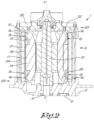
- FIG. 1 shows the motor 3 in detail.
- the magnet-assisted motor 3 is a permanent magnet motor 3.
- the motor 3 comprises a motor housing 10 which incorporates a motor stator 11 and a motor rotor 12 which is rotatably provided in the motor stator 11.
- the motor stator 11 is provided with windings 13, which are typically placed around a laminated core 14, also referred to as laminations.
- the axial ends 15 of these windings 13, also called the 'heads' of the windings 12, are provided with a protective layer 16.
- these heads are provided with a layer which is applied on, over and around the windings 13.
- This protective layer 16 is preferably thermally conductive, electrically insulating and water- and oil-resistant.
- the protective layer 16 may an include an epoxy resin, for example, but a polymer material is another option.
- the protective layer 16 will extend over the entire winding 13 or over the entire motor stator 11.
- the protective layer 16 will typically be a thin layer of for instance 0.1 millimeter thick to one millimeter thick. Of course, it is not ruled out that, for example, the protective layer 16 is between one and five millimeters thick.
- the protective layer 16 may be much thicker, with the axial ends 15 of the windings 13 encapsulated in a protective material.
- the complete windings 13 or the complete motor stator 11 can also be encapsulated in a protective material.
- the motor housing 10 also acts as a cooling jacket 17. It is not ruled out that the motor housing 10 is provided with a separate cooling jacket 17.
- the compressor device 1 is a vertical compressor device 1, with the motor rotor 12 of the magnet-assisted motor 3 extending along an axial direction X-X' which is vertically positioned in normal operation of the compressor device 1, while the magnet-assisted motor 3 forms a head or upper part of compressor device 1 and compressor element 2 forms a base or lower part of the compressor device 1.
- an oil supply line 18 is also provided to inject oil into the magnet-assisted motor 3.
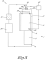
- FIG. 3 shows this oil supply line 18. As can be seen, in this example, but not necessary for the invention, it is part of an oil circuit 19.
- the oil circuit 19 is arranged to direct all oil first to the motor 3 and then to the compressor element 2.
- the oil circuit 19 flows back to motor 3 via oil reservoir 20 and oil cooler 21 to form a closed circuit for the oil.
- Said oil supply line 18 is connected to one or more nozzles 22 which are directed at the heads 15 or axial ends 15 of the windings 13 of the motor stator 11 and the cooling jacket 17 of the motor 3.
- nozzles 22 will spray the oil directly onto the heads 15 of the windings 13 in the form of an oil stream or 'jet'.
- the nozzles 22 will atomize the oil, that is, spray the oil on the heads 15 of the windings 13 in the form of small droplets.
- the above nozzles 22 are located at the axial ends 23 of the motor stator 11 and the motor rotor 12, with the nozzles 22 directed axially.
- a number of nozzles 22 may be provided, for example two to eight and preferably symmetrically located around the axis X-X' of the motor rotor 12.
- nozzles 22 are located at the top, that is at the axial end 23 of the motor 3 facing away from compressor element 2, but it is not ruled out that additional or alternative nozzles 22 are located at the bottom, that is on the axial end 23 of the motor 3 directed at the compressor element 2.
- the nozzles 22 are located on the side of the motor housing 10, that is at the location of the jacket 24 of the motor housing 10, with the nozzles 22 directed radially in this case, so that they are directed to the heads 15 of the windings 13.
- nozzles 22 may be located at the top as well as at the bottom.
- nozzles 22 The exact location of the nozzles 22 will depend on the design of the motor 3 in general and on the motor housing 10 in particular.
- an alternative solution is to design the motor rotor 12 at least partially hollow and to integrate a nozzle 22 in this hollow motor rotor 12.
- the nozzle 22 is directed radially outward, while a radial passage in the motor rotor 12 is provided to allow oil to pass through.
- the oil supply line 18 is connected to the nozzles 22 and to the cooling jacket 17.
- this is done in parallel, because the oil supply line 18 branches off into two branch lines 25a, 25b, as shown in figure 3 .
- a first branch line 25a connects the oil supply line 18 to said nozzles 22 and the second branch line 25b connects the oil supply line 18 to the cooling jacket 17.
- the compressor device 1 is further equipped with means 26 to control the amount of oil flowing to the first and second branch lines 25a, 25b and to a controller 27 to control said control means 26.
- control means 26 are designed as a threeway valve 28, but may also be designed as one regular valve, installed in one of the two branch lines 25a, 25b.
- the compressor device 1 has measuring means 29 to determine the temperature of the heads 15 or axial ends 15 of the windings 13 of the motor stator 11 and the controller 27 is provided with an algorithm to control the regulating means 26 based on the temperature of the heads or axial ends 15 of the windings 13 of the motor stator 11.
- These measuring means 29 include, for example, a temperature sensor.
- these grooves 30 may be situated symmetrically around the axis X-X' of the motor rotor 12.
- the oil which is injected through the nozzles 22, can flow out along these channels or grooves 30.
- the oil may also flow out through the space between the motor rotor 1.2 and the motor stator 11 or through the laminations 14 of the motor stator 11.
- compressor device 1 The operation of compressor device 1 is very simple and as follows.
- compressor element 2 During the operation of compressor element 1, compressor element 2 will be driven by the magnet-assisted motor 3.
- the screw rotors 7 will compress gas that is drawn in through their collaborating action.
- oil will be injected into the compressor element 2 as well as into the motor 3.
- the oil supply line 18 will first direct all oil to the motor 3.
- the second branch line 25b will direct the oil to the cooling jacket 17.
- This oil will be able to draw heat from the motor housing 10 in the known way to cool the motor 3.
- Oil is also directed to the nozzles 22 through the oil supply line 18 and the first branch line 25a.
- the nozzles 22 are placed at an appropriate location that will allow them to atomize the oil at the actual ends 15 of the windings 13 of the motor stator 11.
- the small oil droplets will be able to draw heat from these axial ends 1.5 of the windings 13, which will then be cooled more efficiently than with the oil flowing through the cooling jacket 17.
- the protective layer 16 on the axial ends 15 of the windings 13 protects them from the oil being sprayed on them.
- the controller 27 will control how much oil is directed to the nozzles 22 through the first branch line 25a.
- the controller 27 is provided with an algorithm in this case to control the control means 26 based on the temperature of the windings 13 of the motor stator 11.
- the aforementioned algorithm is such that the controller 27 will control the aforementioned control means 26 so that no oil will flow to the first branch line 25a when the temperature of the axial ends 15 of the windings 13, as measured by the measuring means 29, is lower than a predefined maximum temperature T max .
- the atomized oil can then flow down via three paths, toward the other heads or axial ends 15 of the windings 13 in order to cool these axial ends 15 of the windings 13 as well.
- the oil will also cool the motor stator 11 and possibly the motor rotor 12.
- the oil will also flow by force of gravity through the motor 3 in the direction of compressor element 2.
- the oil will leave the compressor device 1 via outlet 6 along with the compressed gas.
- An oil separator will separate it and it will pass through the oil circuit 19 along the oil reservoir 20 and then enter the oil cooler 21 to be injected back into the motor 3 from there.
- the oil supply to the nozzles 22 and the cooling jacket 17 can also be arranged in series, wherein the oil supply line 18 is directly connected to the aforementioned cooling jacket 17, so that all the oil first goes to the cooling jacket 17 and then to the nozzles 22.
- channels are provided in the motor housing 10, which allow the oil, after being directed through the cooling jacket 17, to be directed to the nozzles 22 for injection into the motor 3.
- oil supply line 18 is connected to the nozzles 22, albeit not directly, but through the cooling jacket 17 and any further channels in the motor housing 10.
Landscapes
- Engineering & Computer Science (AREA)
- Mechanical Engineering (AREA)
- General Engineering & Computer Science (AREA)
- Power Engineering (AREA)
- Microelectronics & Electronic Packaging (AREA)
- Motor Or Generator Cooling System (AREA)
- Compressor (AREA)
- Applications Or Details Of Rotary Compressors (AREA)
Description
- The present invention relates to a compressor device, comprising a magnet-assisted motor, for example a permanent magnet motor, to drive the compressor device.
- More specifically, the invention is intended to ensure optimum cooling of the magnet-assisted motor.
- It is known that the maximum power of a magnet-assisted motor is limited by the maximum temperature of the magnet-assisted motor, in particular the maximum temperature of the stator windings.
- To ensure the proper operation of the magnet-assisted motor, the temperature in these windings must not rise too high.
- By cooling the magnet-assisted motor, for example with a cooling medium such as oil, the maximum power of the magnet-assisted motor can be increased.
- Typically, the magnet-assisted motor is equipped with cooling channels in the magnet-assisted motor housing or jacket through which a cooling medium may flow.
- This means that the generated heat must reach the cooling medium through convection by the air in the stator and then by conduction through the magnet-assisted motor housing.
- In other words, there is a thermal resistance between heat in the windings and in the cooling medium.
- This means cooling of the stator windings is far from optimal, so in practice the maximum power of the magnet-assisted motor can only be increased to a limited degree.
- The document
WO2018083579 discloses a compressor which motor provides a cooling jacket consisting of conduits to allow the passage of cooling oil, whereby nozzles are provided through which the oil enters the jacket. - This invention aims at solving at least one of the aforementioned and other disadvantages.
- For this purpose, the invention relates to a compressor device equipped with:
- a compressor element with an inlet for supplying gas and an outlet for discharging compressed gas;
- a magnet-assisted motor provided with a motor housing including a motor stator and a motor rotor which is rotatably fitted in the motor stator, wherein the motor stator includes windings and wherein the motor housing is provided with or acts as a cooling jacket,
- an oil supply line to allow injecting of oil into the magnet-assisted motor,
- An advantage is that by spraying the oil directly onto the heads or axial ends of the windings, also called 'winding heads', the winding heads can be cooled much more efficiently. The oil will be able to dissipate heat much more effectively due to the lack of thermal resistance between the winding heads and the oil.
- Because the winding heads are provided with a protective layer, they are protected from the oil being sprayed on them and, more importantly, from any condensate in the oil.
- This will prevent any electrical problems caused by the condensate.
- Due to the forced cooling of the winding heads, the temperature will increase less quickly so the maximum motor power can be increased.
- In a practical embodiment, the oil supply line branches out into two branch lines, with a first branch line connecting the oil supply line to said nozzles and the second branch line connecting the oil supply line to the cooling jacket.
- By providing two branch lines, part of the oil can be routed to the cooling jacket to provide the known traditional motor cooling and another part to the nozzle or nozzles to provide the additional, forced cooling of the winding heads.
- For example, general motor cooling can be provided that way, wherein the oil will cool the motor housing to dissipate heat from the motor, as a specific cooling directed at the winding heads, which are typically the motor hotspots.
- In addition, a branched oil supply offers the possibility to adjust the flow rate and/or temperature of each supply according to requirements or necessity.
- In an alternative embodiment, the oil supply line is directly connected to the cooling jacket wherein all the oil first goes to the cooling jacket and then to the nozzles.
- When the oil has passed through the cooling jacket, the oil will then be guided to the nozzles and sprayed onto the winding heads in the motor.
- For example, this may be realized by providing internal channels in the motor and/or motor housing.
- Unlike in the case of said parallel oil flow with two branch lines, such a serial flow offers the advantage that forced integration can be realized.
- Of course it is not ruled out that the oil is first guided to the nozzles to be injected onto the winding heads, and only then goes to the cooling jacket.
- In an alternative embodiment, the motor stator is provided with axially oriented grooves or channels and/or axially oriented grooves or channels are provided in the housing at the location of the motor stator.
- These grooves will allow the injected oil to flow along the motor stator and/or the housing while providing further cooling.
- The injected oil can also flow away between the motor rotor and the motor stator or through laminations of the motor stator.
- To better demonstrate the characteristics of the invention, the following describes, as an example without any restrictive character, some preferred embodiments of a compressor device according to the invention, with reference to the accompanying drawings, wherein:
-
figure 1 schematically shows a cross-section of a part of a compressor device as claimed in the invention; -
figure 2 shows the magnet-assisted motor offigure 1 in more detail; -
figure 3 schematically shows the part of the compressor device shown infigure 1 , together with a related oil circuit. -
Figure 1 is a schematic representation of a compressor device 1 according to the invention. - Compressor device 1 comprised mainly a
compressor element 2 and a magnet-assisted motor 3. - In this case, but not necessary for the invention,
compressor element 2 is provided with a screw compressor element. - It comprises a compressor housing 4 with an inlet 5 for supplying a gas to be compressed and an outlet 6 for supplying compressed gas.
- Said gas may for instance, but not necessary for the invention, be air.
- Two collaborating screw rotors 7 are installed in the compressor housing 4, which can compress gas sucked in by rotation.
- To this end, the screw rotors 7 with their shafts 8 are rotatably fitted in the compressor housing 4 by means of bearings 9.
- One of the two screw rotors 7 is driven by said motor.
-
Figure 2 shows the motor 3 in detail. - In this case, but not necessary for the invention, the magnet-assisted motor 3 is a permanent magnet motor 3.
- The motor 3 comprises a motor housing 10 which incorporates a
motor stator 11 and amotor rotor 12 which is rotatably provided in themotor stator 11. - The
motor stator 11 is provided withwindings 13, which are typically placed around a laminatedcore 14, also referred to as laminations. - According to the invention, the
axial ends 15 of thesewindings 13, also called the 'heads' of thewindings 12, are provided with aprotective layer 16. - This means that these heads are provided with a layer which is applied on, over and around the
windings 13. - This
protective layer 16 is preferably thermally conductive, electrically insulating and water- and oil-resistant. - The
protective layer 16 may an include an epoxy resin, for example, but a polymer material is another option. - It is not ruled out that instead of only the
axial ends 15, thecomplete windings 13 or even thecomplete motor stator 11 have aprotective layer 16. - For that purpose, the
protective layer 16 will extend over the entire winding 13 or over theentire motor stator 11. - The
protective layer 16 will typically be a thin layer of for instance 0.1 millimeter thick to one millimeter thick. Of course, it is not ruled out that, for example, theprotective layer 16 is between one and five millimeters thick. - Alternatively, the
protective layer 16 may be much thicker, with theaxial ends 15 of thewindings 13 encapsulated in a protective material. Obviously, thecomplete windings 13 or thecomplete motor stator 11 can also be encapsulated in a protective material. - In this case, the motor housing 10 also acts as a
cooling jacket 17. It is not ruled out that the motor housing 10 is provided with aseparate cooling jacket 17. - As shown in
figure 1 , the compressor device 1 is a vertical compressor device 1, with themotor rotor 12 of the magnet-assisted motor 3 extending along an axial direction X-X' which is vertically positioned in normal operation of the compressor device 1, while the magnet-assisted motor 3 forms a head or upper part of compressor device 1 andcompressor element 2 forms a base or lower part of the compressor device 1. - In addition, according to the invention, an oil supply line 18 is also provided to inject oil into the magnet-assisted motor 3.
-
Figure 3 shows this oil supply line 18. As can be seen, in this example, but not necessary for the invention, it is part of an oil circuit 19. - In this case, the oil circuit 19 is arranged to direct all oil first to the motor 3 and then to the
compressor element 2. - From the
compressor element 2, the oil circuit 19 flows back to motor 3 viaoil reservoir 20 and oil cooler 21 to form a closed circuit for the oil. - Said oil supply line 18 is connected to one or
more nozzles 22 which are directed at theheads 15 or axial ends 15 of thewindings 13 of themotor stator 11 and the coolingjacket 17 of the motor 3. - These
nozzles 22 will spray the oil directly onto theheads 15 of thewindings 13 in the form of an oil stream or 'jet'. - It is not ruled out that the
nozzles 22 will atomize the oil, that is, spray the oil on theheads 15 of thewindings 13 in the form of small droplets. - In the example shown, the
above nozzles 22 are located at the axial ends 23 of themotor stator 11 and themotor rotor 12, with thenozzles 22 directed axially. - A number of
nozzles 22 may be provided, for example two to eight and preferably symmetrically located around the axis X-X' of themotor rotor 12. - In this case, nozzles 22 are located at the top, that is at the
axial end 23 of the motor 3 facing away fromcompressor element 2, but it is not ruled out that additional oralternative nozzles 22 are located at the bottom, that is on theaxial end 23 of the motor 3 directed at thecompressor element 2. - It is also possible that the
nozzles 22 are located on the side of the motor housing 10, that is at the location of thejacket 24 of the motor housing 10, with thenozzles 22 directed radially in this case, so that they are directed to theheads 15 of thewindings 13. - In this situation too,
nozzles 22 may be located at the top as well as at the bottom. - The exact location of the
nozzles 22 will depend on the design of the motor 3 in general and on the motor housing 10 in particular. - If the motor housing 10 does not allow an oil supply to pass through the motor housing 10, an alternative solution is to design the
motor rotor 12 at least partially hollow and to integrate anozzle 22 in thishollow motor rotor 12. - Obviously, then the
nozzle 22 is directed radially outward, while a radial passage in themotor rotor 12 is provided to allow oil to pass through. - As stated above, the oil supply line 18 is connected to the
nozzles 22 and to the coolingjacket 17. - This means that oil that is guided through the oil supply line 18 to the motor 3 will enter both the
nozzles 22 and the coolingjacket 17. - In the example shown, this is done in parallel, because the oil supply line 18 branches off into two branch lines 25a, 25b, as shown in
figure 3 . - A first branch line 25a connects the oil supply line 18 to said
nozzles 22 and the second branch line 25b connects the oil supply line 18 to the coolingjacket 17. - In this case, the compressor device 1 is further equipped with
means 26 to control the amount of oil flowing to the first and second branch lines 25a, 25b and to a controller 27 to control said control means 26. - This allows the amount of oil flowing to the
nozzles 22 to be controlled, between no oil and all or nearly all of the oil. - If no control means 26 are provided, oil will be injected continuously through the
nozzles 22. - In that case, said control means 26 are designed as a threeway valve 28, but may also be designed as one regular valve, installed in one of the two branch lines 25a, 25b.
- In addition, in this example, the compressor device 1 has measuring means 29 to determine the temperature of the
heads 15 or axial ends 15 of thewindings 13 of themotor stator 11 and the controller 27 is provided with an algorithm to control the regulating means 26 based on the temperature of the heads or axial ends 15 of thewindings 13 of themotor stator 11. - These measuring means 29 include, for example, a temperature sensor.
- In addition, in the example shown, there are also axially oriented
grooves 30 or channels installed in the motor housing 10 at the location of themotor stator 11. - Just like the
nozzles 22, thesegrooves 30 may be situated symmetrically around the axis X-X' of themotor rotor 12. - Alternatively or additionally, it is also possible to provide the axially oriented
grooves 30 or channels in themotor stator 11 itself. - The oil, which is injected through the
nozzles 22, can flow out along these channels orgrooves 30. - The oil may also flow out through the space between the motor rotor 1.2 and the
motor stator 11 or through thelaminations 14 of themotor stator 11. - The operation of compressor device 1 is very simple and as follows.
- During the operation of compressor element 1,
compressor element 2 will be driven by the magnet-assisted motor 3. - The screw rotors 7 will compress gas that is drawn in through their collaborating action.
- During operation, oil will be injected into the
compressor element 2 as well as into the motor 3. - The oil supply line 18 will first direct all oil to the motor 3.
- The second branch line 25b will direct the oil to the cooling
jacket 17. - This oil will be able to draw heat from the motor housing 10 in the known way to cool the motor 3.
- Oil is also directed to the
nozzles 22 through the oil supply line 18 and the first branch line 25a. - As aforementioned, the
nozzles 22 are placed at an appropriate location that will allow them to atomize the oil at the actual ends 15 of thewindings 13 of themotor stator 11. - The small oil droplets will be able to draw heat from these axial ends 1.5 of the
windings 13, which will then be cooled more efficiently than with the oil flowing through the coolingjacket 17. - The
protective layer 16 on the axial ends 15 of thewindings 13 protects them from the oil being sprayed on them. - The controller 27 will control how much oil is directed to the
nozzles 22 through the first branch line 25a. - For that purpose, the controller 27 is provided with an algorithm in this case to control the control means 26 based on the temperature of the
windings 13 of themotor stator 11. - In this case, the aforementioned algorithm is such that the controller 27 will control the aforementioned control means 26 so that no oil will flow to the first branch line 25a when the temperature of the axial ends 15 of the
windings 13, as measured by the measuring means 29, is lower than a predefined maximum temperature Tmax. - In other words, only if the temperature of the
heads 15 ofwindings 13 rises too high so that cooling is required, oil will be atomized onto them. - It is also not ruled out that the quantity of oil that is directed to the
nozzles 22 through the first branch line 25a, is controlled on the basis of the measurements of the measuring means 29. - The atomized oil can then flow down via three paths, toward the other heads or axial ends 15 of the
windings 13 in order to cool these axial ends 15 of thewindings 13 as well. - These three paths are:
- between the motor housing 10 and the
motor stator 11, via the aforementioned axially orientedgrooves 30 or channels provided in themotor stator 11; - between the
motor rotor 12 and themotor stator 11; - through
laminations 14 of themotor stator 11. - The oil will also cool the
motor stator 11 and possibly themotor rotor 12. - In this case, the oil will also flow by force of gravity through the motor 3 in the direction of
compressor element 2. - However, even if it would not concern the vertical compressor element 1, the oil would still flow toward
compressor element 2, by force of the oil pressure and/or vacuum created bycompressor element 2. - When the oil has reached the bottom of motor 3, it will be routed through oil circuit 19 to
compressor element 2, to be injected, for example, into compressor housing 4 or bearings 9. - The oil will leave the compressor device 1 via outlet 6 along with the compressed gas.
- An oil separator will separate it and it will pass through the oil circuit 19 along the
oil reservoir 20 and then enter theoil cooler 21 to be injected back into the motor 3 from there. - Although the above example shows and describes the oil supply to the
nozzles 22 and the coolingjacket 17 in parallel, it is not ruled out that this is done in series. - This means that the oil supply to the
nozzles 22 and the coolingjacket 17 can also be arranged in series, wherein the oil supply line 18 is directly connected to theaforementioned cooling jacket 17, so that all the oil first goes to the coolingjacket 17 and then to thenozzles 22. - In other words, no branch lines 25a, 25b are provided here.
- In this case, channels are provided in the motor housing 10, which allow the oil, after being directed through the cooling
jacket 17, to be directed to thenozzles 22 for injection into the motor 3. - Note that also in this case, the oil supply line 18 is connected to the
nozzles 22, albeit not directly, but through the coolingjacket 17 and any further channels in the motor housing 10. - Such an approach has the advantage of not requiring any additional measures to regulate the oil supply.
- The present invention is by no means limited to the embodiments described as examples and shown in the figures, but a compressor device according to the invention can be implemented in all shapes and sizes without going beyond the scope of the invention as defined by the appended claims
Claims (15)
- Compressor device provided with:- a compressor element (2) with an inlet (5) for supplying gas and an outlet (6) for discharging compressed gas,- a magnet-assisted motor (3) provided with a motor housing (10) in which a motor stator (11) is installed and a motor rotor (12) is rotatably installed in the motor stator (11), wherein the motor stator (11) is provided with windings (13) and wherein the motor housing (10) is provided with or acts as a cooling jacket (17);- an oil supply line (18) for injecting oil into the magnet-assisted motor (3);characterized in that the oil supply line (18) is connected with one or several nozzles (22) directed at heads or axial ends (15) of the windings (13) of the motor stator (11) and with the cooling jacket (17) of the magnet-assisted motor (3) and that heads or axial ends (15) of the windings (13) are covered with a protective layer (16).
- Compressor device according to claim 1, characterized in that the protective layer (16) is thermally conductive, electrically insulating and resistant to water and oil, whereby the protective layer (16) preferably comprises an epoxy resin.
- Compressor device according to one of the previous claims, characterized in that the nozzles (22) are located at one or more of the following locations in the motor housing (10):- at the axial ends (23) of the motor stator (11) and the motor rotor (12), wherein the nozzles (22) are directed axially,- at the side, through the jacket (24) of the motor housing (10), wherein the nozzles (22) are directed radially.
- Compressor device according to one of the previous claims, characterized in that the motor rotor (12) is at least partially hollow, wherein at least one of the nozzles (22) is integrated in the motor rotor (12).
- Compressor device according to one of the previous claims, characterized in that the oil supply line (18) branches out into two branch lines (25a, 25b), wherein a first branch line (25a) connects the oil supply line (18) with said nozzles (22) and the second branch line (25b) connects the oil supply line (18) with the cooling jacket (17).
- Compressor device according to claim 5, characterized in that the compressor device (1) is further provided with control means (26) for controlling the quantity of oil going to the first and second branch lines (25a, 25b) and a controller (27) which will control said means (26).
- Compressor device according to claim 6, characterized in that the compressor device (1) is further provided with measuring means (29) to determine the temperature of the heads or axial ends (15) of the windings (13) of the motor stator (11) and the controller (27) is provided with an algorithm for controlling the control means (26) on the basis of the temperature of heads or axial ends (15) of the windings (13) of the motor stator (11), whereby said algorithm is preferably such that the controller (27) will control said control means (26) in such a way that no oil will flow to the first branch line (25a) when the temperature of the heads or axial ends (15) of the windings (13) is lower than a preset maximum temperature Tmax.
- Compressor device according to one of the previous claims 1-4, characterized in that the oil supply line (18) is directly connected to said cooling jacket (17), wherein all the oil first goes to the cooling jacket (17) and then to the nozzles (22) .
- Compressor device according to one of the previous claims, characterized in that the protective layer (16) extends over the entire winding (13) or over the entire motor stator (11).
- Compressor device according to one of the previous claims, characterized in that at least the heads or axial ends (15) of the windings (13) are encapsulated in a protective material.
- Compressor device according to one of the previous claims, characterized in that the oil supply line (18) is part of an oil circuit (19) which is also part of the compressor device (1), wherein the oil circuit (19) is designed in such a manner that all the oil is first directed to the magnet-assisted motor (3) and then to compressor element (2).
- Compressor device according to one of the previous claims, characterized in that the motor stator (11) is provided with axially oriented grooves (30) or channels and/or that the motor housing (10), at the location of the motor stator (11), is provided with axially oriented grooves (30) or channels.
- Compressor device according to one of the previous claims, characterized in that the nozzles (22) atomize the oil.
- Compressor device according to one of the previous claims, characterized in that the compressor element (2) is a screw compressor element (2).
- Compressor device according to one of the previous claims, characterized in that the compressor device (1) is a vertical compressor device (1), wherein the motor rotor (12) of the magnet-assisted motor (3) extends in an axial direction (X-X') vertically positioned in normal compressor device operation (1), wherein the magnet-assisted motor (3) forms a head or upper part of the compressor device (1) and the compressor element (2) forms a base or lower part of the compressor device (1).
Applications Claiming Priority (2)
| Application Number | Priority Date | Filing Date | Title |
|---|---|---|---|
| BE20195526A BE1027496B1 (en) | 2019-08-12 | 2019-08-12 | Compressor device |
| PCT/IB2020/056562 WO2021028741A1 (en) | 2019-08-12 | 2020-07-13 | Compressor device |
Publications (2)
| Publication Number | Publication Date |
|---|---|
| EP4013965A1 EP4013965A1 (en) | 2022-06-22 |
| EP4013965B1 true EP4013965B1 (en) | 2023-11-22 |
Family
ID=67902268
Family Applications (1)
| Application Number | Title | Priority Date | Filing Date |
|---|---|---|---|
| EP20743844.1A Active EP4013965B1 (en) | 2019-08-12 | 2020-07-13 | Compressor device |
Country Status (10)
| Country | Link |
|---|---|
| US (1) | US11996755B2 (en) |
| EP (1) | EP4013965B1 (en) |
| JP (1) | JP7344367B2 (en) |
| KR (1) | KR102689791B1 (en) |
| CN (3) | CN112398280B (en) |
| BE (1) | BE1027496B1 (en) |
| DK (1) | DK4013965T3 (en) |
| ES (1) | ES2974616T3 (en) |
| PL (1) | PL4013965T3 (en) |
| WO (1) | WO2021028741A1 (en) |
Families Citing this family (4)
| Publication number | Priority date | Publication date | Assignee | Title |
|---|---|---|---|---|
| BE1027496B1 (en) * | 2019-08-12 | 2021-03-16 | Atlas Copco Airpower Nv | Compressor device |
| WO2023215091A1 (en) * | 2022-05-05 | 2023-11-09 | Schlumberger Technology Corporation | Devices, systems, and methods for reducing magnetic particles in a fluid flow |
| US12323025B2 (en) * | 2022-10-24 | 2025-06-03 | Schaeffler Technologies AG & Co. KG | Heat exchanger system for an electric motor with fluid circuits arranged between shafts |
| EP4621239A1 (en) * | 2024-03-18 | 2025-09-24 | Carrier Corporation | Motor cooling in screw compressors |
Citations (8)
| Publication number | Priority date | Publication date | Assignee | Title |
|---|---|---|---|---|
| US4959570A (en) | 1987-07-09 | 1990-09-25 | Fanuc Ltd. | Motor cooling system |
| JPH0343596U (en) | 1989-09-08 | 1991-04-24 | ||
| JP2004343857A (en) | 2003-05-14 | 2004-12-02 | Kobe Steel Ltd | Liquid-cooled motor |
| WO2005080814A1 (en) | 2004-02-23 | 2005-09-01 | Atlas Copco Airpower, Naamloze Vennootschap | Machine with an improved bearing lubrication |
| EP1580434B1 (en) * | 2004-03-26 | 2007-12-12 | Minebea Co., Ltd. | Electric pump |
| WO2018083579A1 (en) | 2016-11-03 | 2018-05-11 | Atlas Copco Airpower, Naamloze Vennootschap | Drive for a compressor element and water injected compressor device provided with such a drive |
| JP2018170941A (en) | 2017-03-30 | 2018-11-01 | 本田技研工業株式会社 | Rotating electrical machine unit and cooling system for rotating electrical machine unit |
| CN109519383A (en) | 2018-12-31 | 2019-03-26 | 杭州久益机械股份有限公司 | A kind of cold integral type helical-lobe compressor of vertical oil and its oily cooling method |
Family Cites Families (30)
| Publication number | Priority date | Publication date | Assignee | Title |
|---|---|---|---|---|
| US3805101A (en) * | 1972-07-03 | 1974-04-16 | Litton Industrial Products | Refrigerant cooled electric motor and method for cooling a motor |
| JPS57121869U (en) | 1981-01-23 | 1982-07-29 | ||
| US5682074A (en) * | 1994-03-02 | 1997-10-28 | Northrop Grumman Corporation | Electric vehicle motor |
| US6201321B1 (en) * | 1998-06-05 | 2001-03-13 | Bayside Controls, Inc. | Apparatus and method for dissipating heat from a motor |
| JP3668616B2 (en) * | 1998-09-17 | 2005-07-06 | 株式会社日立産機システム | Oil-free screw compressor |
| JP3076609U (en) | 2000-02-22 | 2001-04-13 | 鶴田電機工業株式会社 | Built-in motor for refrigerators with part of the winding slots in the stator core being empty slots where no coils are placed |
| JP4190721B2 (en) * | 2000-12-04 | 2008-12-03 | 株式会社日立製作所 | Oil-free screw compressor |
| JP2003032979A (en) | 2001-07-13 | 2003-01-31 | Matsushita Electric Ind Co Ltd | Switch reluctance motor |
| JP2004135398A (en) | 2002-10-09 | 2004-04-30 | Honda Motor Co Ltd | Motor device cooling structure |
| JP2004180479A (en) | 2002-11-29 | 2004-06-24 | Nissan Motor Co Ltd | Motor cooling structure |
| JP2004183499A (en) * | 2002-11-29 | 2004-07-02 | Denso Corp | Electric compressor |
| JP2004211568A (en) | 2002-12-27 | 2004-07-29 | Hitachi Industrial Equipment Systems Co Ltd | Compressed air supply system for fuel cell vehicles |
| JP2004350466A (en) * | 2003-05-26 | 2004-12-09 | Kobe Steel Ltd | Liquid-cooled motor |
| US7009317B2 (en) * | 2004-01-14 | 2006-03-07 | Caterpillar Inc. | Cooling system for an electric motor |
| JP2009118686A (en) * | 2007-11-08 | 2009-05-28 | Aisin Aw Co Ltd | Cooling structure of rotating electric machine |
| US8777596B2 (en) * | 2008-05-06 | 2014-07-15 | Fmc Technologies, Inc. | Flushing system |
| JP5197141B2 (en) * | 2008-05-12 | 2013-05-15 | 株式会社神戸製鋼所 | Two-stage screw compressor and refrigeration system |
| JP2013042588A (en) * | 2011-08-12 | 2013-02-28 | Daikin Ind Ltd | Electric motor |
| BE1020312A3 (en) * | 2012-02-28 | 2013-07-02 | Atlas Copco Airpower Nv | COMPRESSOR DEVICE, AS WELL AS USE OF SUCH SET-UP. |
| GB2501952B (en) * | 2012-10-09 | 2014-03-26 | Integral Powertrain Ltd | A motor and a method of cooling a motor |
| JP6154602B2 (en) * | 2012-12-03 | 2017-06-28 | 株式会社Subaru | Cooling device for rotating electric machine |
| US9293965B2 (en) * | 2013-08-05 | 2016-03-22 | GM Global Technology Operations LLC | Apparatus, system, and method for cooling an electric motor |
| JP2015045290A (en) * | 2013-08-29 | 2015-03-12 | 日立アプライアンス株式会社 | Hermetic compressor |
| JP6197592B2 (en) | 2013-11-12 | 2017-09-20 | マツダ株式会社 | Motor cooling structure |
| JP6982380B2 (en) * | 2016-03-08 | 2021-12-17 | コベルコ・コンプレッサ株式会社 | Screw compressor |
| US11085448B2 (en) * | 2017-04-21 | 2021-08-10 | Atlas Copco Airpower, Naamloze Vennootschap | Oil circuit, oil-free compressor provided with such oil circuit and a method to control lubrication and/or cooling of such oil-free compressor via such oil circuit |
| JP6852639B2 (en) | 2017-10-12 | 2021-03-31 | トヨタ自動車株式会社 | Stator |
| JP6610650B2 (en) | 2017-12-28 | 2019-11-27 | 株式会社富士通ゼネラル | Compressor |
| CN209385342U (en) * | 2018-12-31 | 2019-09-13 | 杭州久益机械股份有限公司 | A kind of cold integral type helical-lobe compressor of vertical oil |
| BE1027496B1 (en) * | 2019-08-12 | 2021-03-16 | Atlas Copco Airpower Nv | Compressor device |
-
2019
- 2019-08-12 BE BE20195526A patent/BE1027496B1/en active IP Right Grant
-
2020
- 2020-07-13 WO PCT/IB2020/056562 patent/WO2021028741A1/en not_active Ceased
- 2020-07-13 KR KR1020227006305A patent/KR102689791B1/en active Active
- 2020-07-13 JP JP2022507821A patent/JP7344367B2/en active Active
- 2020-07-13 US US17/628,408 patent/US11996755B2/en active Active
- 2020-07-13 EP EP20743844.1A patent/EP4013965B1/en active Active
- 2020-07-13 PL PL20743844.1T patent/PL4013965T3/en unknown
- 2020-07-13 ES ES20743844T patent/ES2974616T3/en active Active
- 2020-07-13 DK DK20743844.1T patent/DK4013965T3/en active
- 2020-07-22 CN CN202010710237.4A patent/CN112398280B/en active Active
- 2020-07-22 CN CN202021461992.5U patent/CN212811499U/en not_active Withdrawn - After Issue
- 2020-07-22 CN CN202510984015.4A patent/CN120728977A/en active Pending
Patent Citations (8)
| Publication number | Priority date | Publication date | Assignee | Title |
|---|---|---|---|---|
| US4959570A (en) | 1987-07-09 | 1990-09-25 | Fanuc Ltd. | Motor cooling system |
| JPH0343596U (en) | 1989-09-08 | 1991-04-24 | ||
| JP2004343857A (en) | 2003-05-14 | 2004-12-02 | Kobe Steel Ltd | Liquid-cooled motor |
| WO2005080814A1 (en) | 2004-02-23 | 2005-09-01 | Atlas Copco Airpower, Naamloze Vennootschap | Machine with an improved bearing lubrication |
| EP1580434B1 (en) * | 2004-03-26 | 2007-12-12 | Minebea Co., Ltd. | Electric pump |
| WO2018083579A1 (en) | 2016-11-03 | 2018-05-11 | Atlas Copco Airpower, Naamloze Vennootschap | Drive for a compressor element and water injected compressor device provided with such a drive |
| JP2018170941A (en) | 2017-03-30 | 2018-11-01 | 本田技研工業株式会社 | Rotating electrical machine unit and cooling system for rotating electrical machine unit |
| CN109519383A (en) | 2018-12-31 | 2019-03-26 | 杭州久益机械股份有限公司 | A kind of cold integral type helical-lobe compressor of vertical oil and its oily cooling method |
Non-Patent Citations (1)
| Title |
|---|
| ANONYMOUS: "Electromagnetic coil", WIKIPEDIA, 12 July 2019 (2019-07-12), pages 1 - 7, XP093208643, Retrieved from the Internet <URL:https://en.wikipedia.org/wiki/Electromagnetic_coil> [retrieved on 20240925] |
Also Published As
| Publication number | Publication date |
|---|---|
| PL4013965T3 (en) | 2024-03-25 |
| JP7344367B2 (en) | 2023-09-13 |
| WO2021028741A1 (en) | 2021-02-18 |
| CN120728977A (en) | 2025-09-30 |
| US20220271610A1 (en) | 2022-08-25 |
| CN112398280A (en) | 2021-02-23 |
| BE1027496A1 (en) | 2021-03-08 |
| US11996755B2 (en) | 2024-05-28 |
| KR20220042404A (en) | 2022-04-05 |
| BE1027496B1 (en) | 2021-03-16 |
| EP4013965A1 (en) | 2022-06-22 |
| CN112398280B (en) | 2025-07-25 |
| KR102689791B1 (en) | 2024-07-29 |
| DK4013965T3 (en) | 2024-02-26 |
| CN212811499U (en) | 2021-03-26 |
| ES2974616T3 (en) | 2024-06-28 |
| JP2022544479A (en) | 2022-10-19 |
| BR112022002472A2 (en) | 2022-05-03 |
Similar Documents
| Publication | Publication Date | Title |
|---|---|---|
| EP4013965B1 (en) | Compressor device | |
| CN111884428B (en) | Motors, motor cooling systems and electric vehicles | |
| CN108432093B (en) | Electric machine | |
| US10439477B2 (en) | Pressurized and gravity-fed liquid cooling of electric motor | |
| US7683499B2 (en) | Natural gas turbine generator | |
| EP2667486B2 (en) | Electric machine rotor cooling method | |
| US9780625B2 (en) | Cooling stator coils of an electric motor | |
| US20100231066A1 (en) | Electrical machine with permanent magnets | |
| US20090267426A1 (en) | Liquid-cooled electric machine and method for cooling such electric machine | |
| KR101478468B1 (en) | Rotary electric machine apparatus | |
| JP7053886B2 (en) | Motor oil cooling structure | |
| CN106887914A (en) | Motor with cooled armature spindle | |
| US20220263384A1 (en) | Thermal management techniques for electric motors | |
| JP4567212B2 (en) | Cooling structure of rotating electric machine | |
| US20160204680A1 (en) | Electric machine with combined air and water cooling | |
| JP5920108B2 (en) | Rotating electrical machine equipment | |
| RU2788858C1 (en) | Compressor device | |
| KR100726461B1 (en) | Motor Cooling System Using Vortex Tube | |
| EP4329165A1 (en) | Cooling end turns in high power density electric generators | |
| BR112022002472B1 (en) | COMPRESSOR DEVICE | |
| KR102723745B1 (en) | Combined oil cooling concept for electric machines with rotor-integrated clutch, electric machines, drive trains and methods for cooling electric machines | |
| CN222735886U (en) | Oil-cooled motor stator and motor | |
| US20160254729A1 (en) | Fan directing element for an electric machine | |
| CN210578075U (en) | Motor cooling device and motor | |
| CN121216765A (en) | An oil-cooled motor stator and motor |
Legal Events
| Date | Code | Title | Description |
|---|---|---|---|
| STAA | Information on the status of an ep patent application or granted ep patent |
Free format text: STATUS: UNKNOWN |
|
| STAA | Information on the status of an ep patent application or granted ep patent |
Free format text: STATUS: THE INTERNATIONAL PUBLICATION HAS BEEN MADE |
|
| PUAI | Public reference made under article 153(3) epc to a published international application that has entered the european phase |
Free format text: ORIGINAL CODE: 0009012 |
|
| STAA | Information on the status of an ep patent application or granted ep patent |
Free format text: STATUS: REQUEST FOR EXAMINATION WAS MADE |
|
| 17P | Request for examination filed |
Effective date: 20220124 |
|
| AK | Designated contracting states |
Kind code of ref document: A1 Designated state(s): AL AT BE BG CH CY CZ DE DK EE ES FI FR GB GR HR HU IE IS IT LI LT LU LV MC MK MT NL NO PL PT RO RS SE SI SK SM TR |
|
| DAV | Request for validation of the european patent (deleted) | ||
| DAX | Request for extension of the european patent (deleted) | ||
| GRAP | Despatch of communication of intention to grant a patent |
Free format text: ORIGINAL CODE: EPIDOSNIGR1 |
|
| STAA | Information on the status of an ep patent application or granted ep patent |
Free format text: STATUS: GRANT OF PATENT IS INTENDED |
|
| GRAS | Grant fee paid |
Free format text: ORIGINAL CODE: EPIDOSNIGR3 |
|
| GRAA | (expected) grant |
Free format text: ORIGINAL CODE: 0009210 |
|
| STAA | Information on the status of an ep patent application or granted ep patent |
Free format text: STATUS: THE PATENT HAS BEEN GRANTED |
|
| INTG | Intention to grant announced |
Effective date: 20230925 |
|
| AK | Designated contracting states |
Kind code of ref document: B1 Designated state(s): AL AT BE BG CH CY CZ DE DK EE ES FI FR GB GR HR HU IE IS IT LI LT LU LV MC MK MT NL NO PL PT RO RS SE SI SK SM TR |
|
| REG | Reference to a national code |
Ref country code: GB Ref legal event code: FG4D |
|
| REG | Reference to a national code |
Ref country code: CH Ref legal event code: EP Ref country code: DE Ref legal event code: R096 Ref document number: 602020021521 Country of ref document: DE |
|
| REG | Reference to a national code |
Ref country code: IE Ref legal event code: FG4D |
|
| P01 | Opt-out of the competence of the unified patent court (upc) registered |
Effective date: 20231229 |
|
| REG | Reference to a national code |
Ref country code: NL Ref legal event code: FP |
|
| REG | Reference to a national code |
Ref country code: DK Ref legal event code: T3 Effective date: 20240220 |
|
| REG | Reference to a national code |
Ref country code: LT Ref legal event code: MG9D |
|
| PG25 | Lapsed in a contracting state [announced via postgrant information from national office to epo] |
Ref country code: GR Free format text: LAPSE BECAUSE OF FAILURE TO SUBMIT A TRANSLATION OF THE DESCRIPTION OR TO PAY THE FEE WITHIN THE PRESCRIBED TIME-LIMIT Effective date: 20240223 |
|
| PG25 | Lapsed in a contracting state [announced via postgrant information from national office to epo] |
Ref country code: IS Free format text: LAPSE BECAUSE OF FAILURE TO SUBMIT A TRANSLATION OF THE DESCRIPTION OR TO PAY THE FEE WITHIN THE PRESCRIBED TIME-LIMIT Effective date: 20240322 |
|
| PG25 | Lapsed in a contracting state [announced via postgrant information from national office to epo] |
Ref country code: LT Free format text: LAPSE BECAUSE OF FAILURE TO SUBMIT A TRANSLATION OF THE DESCRIPTION OR TO PAY THE FEE WITHIN THE PRESCRIBED TIME-LIMIT Effective date: 20231122 |
|
| REG | Reference to a national code |
Ref country code: AT Ref legal event code: MK05 Ref document number: 1634079 Country of ref document: AT Kind code of ref document: T Effective date: 20231122 Ref country code: EE Ref legal event code: FG4A Ref document number: E024041 Country of ref document: EE Effective date: 20240112 |
|
| PG25 | Lapsed in a contracting state [announced via postgrant information from national office to epo] |
Ref country code: AT Free format text: LAPSE BECAUSE OF FAILURE TO SUBMIT A TRANSLATION OF THE DESCRIPTION OR TO PAY THE FEE WITHIN THE PRESCRIBED TIME-LIMIT Effective date: 20231122 |
|
| PG25 | Lapsed in a contracting state [announced via postgrant information from national office to epo] |
Ref country code: LT Free format text: LAPSE BECAUSE OF FAILURE TO SUBMIT A TRANSLATION OF THE DESCRIPTION OR TO PAY THE FEE WITHIN THE PRESCRIBED TIME-LIMIT Effective date: 20231122 Ref country code: IS Free format text: LAPSE BECAUSE OF FAILURE TO SUBMIT A TRANSLATION OF THE DESCRIPTION OR TO PAY THE FEE WITHIN THE PRESCRIBED TIME-LIMIT Effective date: 20240322 Ref country code: GR Free format text: LAPSE BECAUSE OF FAILURE TO SUBMIT A TRANSLATION OF THE DESCRIPTION OR TO PAY THE FEE WITHIN THE PRESCRIBED TIME-LIMIT Effective date: 20240223 Ref country code: BG Free format text: LAPSE BECAUSE OF FAILURE TO SUBMIT A TRANSLATION OF THE DESCRIPTION OR TO PAY THE FEE WITHIN THE PRESCRIBED TIME-LIMIT Effective date: 20240222 Ref country code: AT Free format text: LAPSE BECAUSE OF FAILURE TO SUBMIT A TRANSLATION OF THE DESCRIPTION OR TO PAY THE FEE WITHIN THE PRESCRIBED TIME-LIMIT Effective date: 20231122 Ref country code: PT Free format text: LAPSE BECAUSE OF FAILURE TO SUBMIT A TRANSLATION OF THE DESCRIPTION OR TO PAY THE FEE WITHIN THE PRESCRIBED TIME-LIMIT Effective date: 20240322 |
|
| PG25 | Lapsed in a contracting state [announced via postgrant information from national office to epo] |
Ref country code: SE Free format text: LAPSE BECAUSE OF FAILURE TO SUBMIT A TRANSLATION OF THE DESCRIPTION OR TO PAY THE FEE WITHIN THE PRESCRIBED TIME-LIMIT Effective date: 20231122 Ref country code: RS Free format text: LAPSE BECAUSE OF FAILURE TO SUBMIT A TRANSLATION OF THE DESCRIPTION OR TO PAY THE FEE WITHIN THE PRESCRIBED TIME-LIMIT Effective date: 20231122 Ref country code: NO Free format text: LAPSE BECAUSE OF FAILURE TO SUBMIT A TRANSLATION OF THE DESCRIPTION OR TO PAY THE FEE WITHIN THE PRESCRIBED TIME-LIMIT Effective date: 20240222 Ref country code: LV Free format text: LAPSE BECAUSE OF FAILURE TO SUBMIT A TRANSLATION OF THE DESCRIPTION OR TO PAY THE FEE WITHIN THE PRESCRIBED TIME-LIMIT Effective date: 20231122 Ref country code: HR Free format text: LAPSE BECAUSE OF FAILURE TO SUBMIT A TRANSLATION OF THE DESCRIPTION OR TO PAY THE FEE WITHIN THE PRESCRIBED TIME-LIMIT Effective date: 20231122 |
|
| REG | Reference to a national code |
Ref country code: ES Ref legal event code: FG2A Ref document number: 2974616 Country of ref document: ES Kind code of ref document: T3 Effective date: 20240628 |
|
| PG25 | Lapsed in a contracting state [announced via postgrant information from national office to epo] |
Ref country code: SK Free format text: LAPSE BECAUSE OF FAILURE TO SUBMIT A TRANSLATION OF THE DESCRIPTION OR TO PAY THE FEE WITHIN THE PRESCRIBED TIME-LIMIT Effective date: 20231122 |
|
| PG25 | Lapsed in a contracting state [announced via postgrant information from national office to epo] |
Ref country code: SM Free format text: LAPSE BECAUSE OF FAILURE TO SUBMIT A TRANSLATION OF THE DESCRIPTION OR TO PAY THE FEE WITHIN THE PRESCRIBED TIME-LIMIT Effective date: 20231122 Ref country code: SK Free format text: LAPSE BECAUSE OF FAILURE TO SUBMIT A TRANSLATION OF THE DESCRIPTION OR TO PAY THE FEE WITHIN THE PRESCRIBED TIME-LIMIT Effective date: 20231122 Ref country code: RO Free format text: LAPSE BECAUSE OF FAILURE TO SUBMIT A TRANSLATION OF THE DESCRIPTION OR TO PAY THE FEE WITHIN THE PRESCRIBED TIME-LIMIT Effective date: 20231122 |
|
| REG | Reference to a national code |
Ref country code: DE Ref legal event code: R026 Ref document number: 602020021521 Country of ref document: DE |
|
| PLBI | Opposition filed |
Free format text: ORIGINAL CODE: 0009260 |
|
| PGFP | Annual fee paid to national office [announced via postgrant information from national office to epo] |
Ref country code: LU Payment date: 20240729 Year of fee payment: 5 |
|
| PLAX | Notice of opposition and request to file observation + time limit sent |
Free format text: ORIGINAL CODE: EPIDOSNOBS2 |
|
| 26 | Opposition filed |
Opponent name: KAESER KOMPRESSOREN SE Effective date: 20240814 |
|
| PGFP | Annual fee paid to national office [announced via postgrant information from national office to epo] |
Ref country code: IE Payment date: 20240729 Year of fee payment: 5 |
|
| PG25 | Lapsed in a contracting state [announced via postgrant information from national office to epo] |
Ref country code: SI Free format text: LAPSE BECAUSE OF FAILURE TO SUBMIT A TRANSLATION OF THE DESCRIPTION OR TO PAY THE FEE WITHIN THE PRESCRIBED TIME-LIMIT Effective date: 20231122 |
|
| PG25 | Lapsed in a contracting state [announced via postgrant information from national office to epo] |
Ref country code: SI Free format text: LAPSE BECAUSE OF FAILURE TO SUBMIT A TRANSLATION OF THE DESCRIPTION OR TO PAY THE FEE WITHIN THE PRESCRIBED TIME-LIMIT Effective date: 20231122 |
|
| PLBB | Reply of patent proprietor to notice(s) of opposition received |
Free format text: ORIGINAL CODE: EPIDOSNOBS3 |
|
| PG25 | Lapsed in a contracting state [announced via postgrant information from national office to epo] |
Ref country code: MC Free format text: LAPSE BECAUSE OF FAILURE TO SUBMIT A TRANSLATION OF THE DESCRIPTION OR TO PAY THE FEE WITHIN THE PRESCRIBED TIME-LIMIT Effective date: 20231122 |
|
| PGFP | Annual fee paid to national office [announced via postgrant information from national office to epo] |
Ref country code: PL Payment date: 20250618 Year of fee payment: 6 |
|
| PGFP | Annual fee paid to national office [announced via postgrant information from national office to epo] |
Ref country code: EE Payment date: 20250619 Year of fee payment: 6 |
|
| PGFP | Annual fee paid to national office [announced via postgrant information from national office to epo] |
Ref country code: CZ Payment date: 20250623 Year of fee payment: 6 |
|
| PGFP | Annual fee paid to national office [announced via postgrant information from national office to epo] |
Ref country code: NL Payment date: 20250726 Year of fee payment: 6 |
|
| PG25 | Lapsed in a contracting state [announced via postgrant information from national office to epo] |
Ref country code: FI Free format text: LAPSE BECAUSE OF FAILURE TO SUBMIT A TRANSLATION OF THE DESCRIPTION OR TO PAY THE FEE WITHIN THE PRESCRIBED TIME-LIMIT Effective date: 20231122 |
|
| PGFP | Annual fee paid to national office [announced via postgrant information from national office to epo] |
Ref country code: ES Payment date: 20250801 Year of fee payment: 6 |
|
| PGFP | Annual fee paid to national office [announced via postgrant information from national office to epo] |
Ref country code: DE Payment date: 20250729 Year of fee payment: 6 Ref country code: DK Payment date: 20250725 Year of fee payment: 6 |
|
| PGFP | Annual fee paid to national office [announced via postgrant information from national office to epo] |
Ref country code: TR Payment date: 20250709 Year of fee payment: 6 Ref country code: IT Payment date: 20250721 Year of fee payment: 6 |
|
| PGFP | Annual fee paid to national office [announced via postgrant information from national office to epo] |
Ref country code: GB Payment date: 20250728 Year of fee payment: 6 Ref country code: BE Payment date: 20250728 Year of fee payment: 6 |
|
| PGFP | Annual fee paid to national office [announced via postgrant information from national office to epo] |
Ref country code: FR Payment date: 20250725 Year of fee payment: 6 |
|
| PGFP | Annual fee paid to national office [announced via postgrant information from national office to epo] |
Ref country code: CH Payment date: 20250801 Year of fee payment: 6 |
|
| PG25 | Lapsed in a contracting state [announced via postgrant information from national office to epo] |
Ref country code: CY Free format text: LAPSE BECAUSE OF FAILURE TO SUBMIT A TRANSLATION OF THE DESCRIPTION OR TO PAY THE FEE WITHIN THE PRESCRIBED TIME-LIMIT; INVALID AB INITIO Effective date: 20200713 |
|
| PG25 | Lapsed in a contracting state [announced via postgrant information from national office to epo] |
Ref country code: HU Free format text: LAPSE BECAUSE OF FAILURE TO SUBMIT A TRANSLATION OF THE DESCRIPTION OR TO PAY THE FEE WITHIN THE PRESCRIBED TIME-LIMIT; INVALID AB INITIO Effective date: 20200713 |
|
| PG25 | Lapsed in a contracting state [announced via postgrant information from national office to epo] |
Ref country code: LU Free format text: LAPSE BECAUSE OF NON-PAYMENT OF DUE FEES Effective date: 20250713 |