EP4013963B1 - Piston for reciprocating compressor having complementary sealing elements - Google Patents
Piston for reciprocating compressor having complementary sealing elements Download PDFInfo
- Publication number
- EP4013963B1 EP4013963B1 EP20767875.6A EP20767875A EP4013963B1 EP 4013963 B1 EP4013963 B1 EP 4013963B1 EP 20767875 A EP20767875 A EP 20767875A EP 4013963 B1 EP4013963 B1 EP 4013963B1
- Authority
- EP
- European Patent Office
- Prior art keywords
- piston
- sealing
- along
- seat
- piston body
- Prior art date
- Legal status (The legal status is an assumption and is not a legal conclusion. Google has not performed a legal analysis and makes no representation as to the accuracy of the status listed.)
- Active
Links
Images


Classifications
-
- F—MECHANICAL ENGINEERING; LIGHTING; HEATING; WEAPONS; BLASTING
- F04—POSITIVE - DISPLACEMENT MACHINES FOR LIQUIDS; PUMPS FOR LIQUIDS OR ELASTIC FLUIDS
- F04B—POSITIVE-DISPLACEMENT MACHINES FOR LIQUIDS; PUMPS
- F04B39/00—Component parts, details, or accessories, of pumps or pumping systems specially adapted for elastic fluids, not otherwise provided for in, or of interest apart from, groups F04B25/00 - F04B37/00
- F04B39/0005—Component parts, details, or accessories, of pumps or pumping systems specially adapted for elastic fluids, not otherwise provided for in, or of interest apart from, groups F04B25/00 - F04B37/00 adaptations of pistons
-
- F—MECHANICAL ENGINEERING; LIGHTING; HEATING; WEAPONS; BLASTING
- F04—POSITIVE - DISPLACEMENT MACHINES FOR LIQUIDS; PUMPS FOR LIQUIDS OR ELASTIC FLUIDS
- F04B—POSITIVE-DISPLACEMENT MACHINES FOR LIQUIDS; PUMPS
- F04B39/00—Component parts, details, or accessories, of pumps or pumping systems specially adapted for elastic fluids, not otherwise provided for in, or of interest apart from, groups F04B25/00 - F04B37/00
-
- F—MECHANICAL ENGINEERING; LIGHTING; HEATING; WEAPONS; BLASTING
- F04—POSITIVE - DISPLACEMENT MACHINES FOR LIQUIDS; PUMPS FOR LIQUIDS OR ELASTIC FLUIDS
- F04B—POSITIVE-DISPLACEMENT MACHINES FOR LIQUIDS; PUMPS
- F04B53/00—Component parts, details or accessories not provided for in, or of interest apart from, groups F04B1/00 - F04B23/00 or F04B39/00 - F04B47/00
- F04B53/02—Packing the free space between cylinders and pistons
-
- F—MECHANICAL ENGINEERING; LIGHTING; HEATING; WEAPONS; BLASTING
- F04—POSITIVE - DISPLACEMENT MACHINES FOR LIQUIDS; PUMPS FOR LIQUIDS OR ELASTIC FLUIDS
- F04B—POSITIVE-DISPLACEMENT MACHINES FOR LIQUIDS; PUMPS
- F04B53/00—Component parts, details or accessories not provided for in, or of interest apart from, groups F04B1/00 - F04B23/00 or F04B39/00 - F04B47/00
- F04B53/14—Pistons, piston-rods or piston-rod connections
- F04B53/143—Sealing provided on the piston
-
- F—MECHANICAL ENGINEERING; LIGHTING; HEATING; WEAPONS; BLASTING
- F16—ENGINEERING ELEMENTS AND UNITS; GENERAL MEASURES FOR PRODUCING AND MAINTAINING EFFECTIVE FUNCTIONING OF MACHINES OR INSTALLATIONS; THERMAL INSULATION IN GENERAL
- F16J—PISTONS; CYLINDERS; SEALINGS
- F16J9/00—Piston-rings, e.g. non-metallic piston-rings, seats therefor; Ring sealings of similar construction
- F16J9/10—Special members for adjusting the rings
-
- F—MECHANICAL ENGINEERING; LIGHTING; HEATING; WEAPONS; BLASTING
- F16—ENGINEERING ELEMENTS AND UNITS; GENERAL MEASURES FOR PRODUCING AND MAINTAINING EFFECTIVE FUNCTIONING OF MACHINES OR INSTALLATIONS; THERMAL INSULATION IN GENERAL
- F16J—PISTONS; CYLINDERS; SEALINGS
- F16J9/00—Piston-rings, e.g. non-metallic piston-rings, seats therefor; Ring sealings of similar construction
- F16J9/12—Details
- F16J9/14—Joint-closures
- F16J9/18—Joint-closures with separate bridge-elements
-
- F—MECHANICAL ENGINEERING; LIGHTING; HEATING; WEAPONS; BLASTING
- F16—ENGINEERING ELEMENTS AND UNITS; GENERAL MEASURES FOR PRODUCING AND MAINTAINING EFFECTIVE FUNCTIONING OF MACHINES OR INSTALLATIONS; THERMAL INSULATION IN GENERAL
- F16J—PISTONS; CYLINDERS; SEALINGS
- F16J9/00—Piston-rings, e.g. non-metallic piston-rings, seats therefor; Ring sealings of similar construction
- F16J9/26—Piston-rings, e.g. non-metallic piston-rings, seats therefor; Ring sealings of similar construction characterised by the use of particular materials
-
- F—MECHANICAL ENGINEERING; LIGHTING; HEATING; WEAPONS; BLASTING
- F16—ENGINEERING ELEMENTS AND UNITS; GENERAL MEASURES FOR PRODUCING AND MAINTAINING EFFECTIVE FUNCTIONING OF MACHINES OR INSTALLATIONS; THERMAL INSULATION IN GENERAL
- F16J—PISTONS; CYLINDERS; SEALINGS
- F16J15/00—Sealings
- F16J15/16—Sealings between relatively-moving surfaces
- F16J15/18—Sealings between relatively-moving surfaces with stuffing-boxes for elastic or plastic packings
- F16J15/188—Split assemblies
-
- F—MECHANICAL ENGINEERING; LIGHTING; HEATING; WEAPONS; BLASTING
- F16—ENGINEERING ELEMENTS AND UNITS; GENERAL MEASURES FOR PRODUCING AND MAINTAINING EFFECTIVE FUNCTIONING OF MACHINES OR INSTALLATIONS; THERMAL INSULATION IN GENERAL
- F16J—PISTONS; CYLINDERS; SEALINGS
- F16J15/00—Sealings
- F16J15/16—Sealings between relatively-moving surfaces
- F16J15/18—Sealings between relatively-moving surfaces with stuffing-boxes for elastic or plastic packings
- F16J15/24—Sealings between relatively-moving surfaces with stuffing-boxes for elastic or plastic packings with radially or tangentially compressed packing
-
- F—MECHANICAL ENGINEERING; LIGHTING; HEATING; WEAPONS; BLASTING
- F16—ENGINEERING ELEMENTS AND UNITS; GENERAL MEASURES FOR PRODUCING AND MAINTAINING EFFECTIVE FUNCTIONING OF MACHINES OR INSTALLATIONS; THERMAL INSULATION IN GENERAL
- F16J—PISTONS; CYLINDERS; SEALINGS
- F16J15/00—Sealings
- F16J15/56—Other sealings for reciprocating rods
-
- F—MECHANICAL ENGINEERING; LIGHTING; HEATING; WEAPONS; BLASTING
- F16—ENGINEERING ELEMENTS AND UNITS; GENERAL MEASURES FOR PRODUCING AND MAINTAINING EFFECTIVE FUNCTIONING OF MACHINES OR INSTALLATIONS; THERMAL INSULATION IN GENERAL
- F16J—PISTONS; CYLINDERS; SEALINGS
- F16J9/00—Piston-rings, e.g. non-metallic piston-rings, seats therefor; Ring sealings of similar construction
- F16J9/06—Piston-rings, e.g. non-metallic piston-rings, seats therefor; Ring sealings of similar construction using separate springs or elastic elements expanding the rings; Springs therefor ; Expansion by wedging
Definitions
- This invention generally relates to the field of reciprocating compressors; in particular, the invention relates to a piston for compressing pneumatic fluid in a cylinder, the piston comprising a plurality of sealing elements of complementary shape.
- the seal in a cylinder-piston mechanism is ensured through the use of a so-called elastic band, that is, a sealing ring arranged in a ring-shaped seat formed along the circumferential perimeter of the piston body.
- a so-called elastic band that is, a sealing ring arranged in a ring-shaped seat formed along the circumferential perimeter of the piston body.
- Fig. 1 which is a cross section along a radial plane of a cylinder C - piston P mechanism according to the prior art
- said ring-shaped seat S is shaped with a given depth d and with a given height h.
- the sealing ring R arranged in the seat has slightly smaller dimensions than the ring-shaped seat S, so as to allow that, when the piston P moves in a compression stroke, the sealing ring R is pushed downwards (in Fig.
- the sealing ring R in order to be easily mounted in the ring-shaped seat S, is not completely closed along the circumference but has a planform having a discontinuity D, wherein a radially outer protruding element E1 seals the passage by contact with an opposite radially inner formation E2.
- Such sealing rings are generally open, and may have different geometries at their ends, whereby the one shown is only one of the conventional geometries.
- Such protruding element due to the elastic compression of the sealing ring, is subjected to more intense wear than the rest of the sealing ring; furthermore, due to its necessarily smaller radial thickness with respect to that of the rest of the sealing ring (as clearly shown in Fig. 2 ), the protruding element wears rapidly. In this way, the known sealing rings lose their sealing capacity as soon as the wear is such as to damage or break at least this protruding element.
- a sealing ring according to the prior art may maintain the seal until wear has subtracted about a quarter of the radial thickness of the sealing ring.
- conventional sealing rings being housed in a ring-shaped seat, may not be oriented angularly, and therefore it is not possible to distribute the wear load in predefined or preferable areas of the ring, more or less sensitive to wear.
- EP3246569 A1 discloses a tangentially cut rod packing ring comprising a first ring formed from a plurality of segments
- CA2847760 A1 discloses a piston seal assembly comprising a seal and a seal energizer which supports the seal.
- the object of this invention is to overcome the drawbacks described and other drawbacks of the prior art and to provide a piston wherein the seal is ensured for a longer operating time.
- a further object of this invention is to provide a piston which allows an operator to understand easily and in time if the seal is still optimal or if the wear from use makes maintenance necessary.
- a piston for compressing a pneumatic fluid into a cylinder having the features defined in claim 1.
- axial shall mean a direction extending along or parallel to the longitudinal axis of the piston and/or cylinder
- radial shall mean a direction extending along a radius of the piston and/or cylinder and passing through the longitudinal axis of the same and/or a plane passing through the longitudinal axis of the piston and/or cylinder and a radius of the same
- transverse shall mean a direction extending perpendicular to the longitudinal axis of the piston and/or cylinder and/or a plane perpendicular to the longitudinal axis of the piston and/or cylinder and on which a radius of the same lies.
- a piston for compressing a pneumatic fluid in a cylinder C according to the invention is generally indicated with 10.
- the piston 10 essentially comprises a piston body 12 and a sealing assembly 14.
- the piston body 12 is generally cylindrical in shape, and is arranged in use inside the cylinder C so as to be able to slide along an axial direction z for compressing a fluid in the cylinder C.
- the piston body 12 has a side wall 16, which in use faces an inner wall of the cylinder C, and a top wall 18, which in use defines, together with the cylinder C, a compression chamber CC.
- a seat 22 for accommodating the sealing assembly 14 is defined.
- the piston body 12 comprises two parts, in particular a first part 12a and a second part 12b.
- the first part 12a is comprised between the top wall 18 of the piston body 12 and the seat 22 thereof, while the second part 12b comprises the remaining part of the piston body 12.
- the first part 12a is preferably removable from the second part 12b, so as to facilitate the installation of the sealing assembly 14 within the seat 22.
- the sealing assembly 14 is housed in the seat 22 and is adapted to ensure the fluid-tightness of the compression chamber CC along said circumferential perimeter 20.
- the sealing assembly 14 comprises a plurality of sealing elements 24, which have shapes complementary to one another, and which are configured so that the wear of a particular sealing element 24 along said circumferential perimeter 20 caused by the reciprocating compression movement of the piston 10 corresponds to a sliding along a radially outer direction r of at least one adjacent sealing element 24.
- the sealing elements 24 of the sealing group 14 are preferably made of a material based on carbon-filled polytetrafluoroethylene, or even more preferably boron nitride-filled, so as to be able to withstand the high temperatures to which they are subjected and, at the same time, ensure a low friction coefficient.
- Fig. 4a to 8 are different embodiments of the sealing elements 24.
- the sealing assembly 14 comprises four sealing elements, in particular a pair of first sealing elements 24 and a pair of second sealing elements 24'.
- Each first sealing element 24 has, at least at a radially outer portion, a substantially triangular planform.
- each second sealing element 24' has, at least at a radially outer portion, a substantially circular sector planform.
- the first sealing elements 24 and the second sealing elements 24' are arranged in contact with one another in pairs, and slidable relative to one another along planes A and B, which are non-radial and non-parallel to one another and arranged converging in a radially outer direction.
- the plane A and the plane B are, in effect, perpendicular to the transverse plane shown in Fig. 4a and 4b but not parallel to, nor coinciding with, a radial plane.
- the sealing assembly 14 is shown in a first operating condition, i.e., in an installation or initial condition.
- Fig. 4b on the other hand, the sealing assembly 14 is shown in a second operating condition, wherein the first sealing elements 24 and the second sealing elements 24' have moved in a radially outer direction, since the compressed air contained in the compression chamber CC may pass into the seat 22 and slip between the sealing elements 24 and 24' as a result of wear.
- the sealing elements 24 and 24' wear out, they are pushed in a radially outer direction ensuring the seal along the circumferential perimeter 20.
- the radially outer portion of the sealing elements 24 and 24' jointly defines a continuous profile along said circumferential perimeter 20 in such a way as to maintain the fluid-tight seal of the compression chamber CC.
- the cross section of the piston body 12 along a transverse plane at the seat 22 has substantially a cross shape with beveled corners; obviously both the length and the thickness of the arms of this cross may be made in dimensions and proportions different from those shown in Fig. 4a and 4b .
- Fig. 5a and 5b show a second embodiment of the invention, under operating conditions similar to those described with respect to Fig. 4a and 4b , respectively.
- This second embodiment differs from the first embodiment described due to the presence of four through holes 26 on the top wall 18 of the piston body 12, adapted to put the compression chamber CC in fluid communication with the seat 22 to facilitate the passage of compressed air towards the radially inner area of the seat 22 and, therefore, pushing the first and second sealing elements 24 and 24' in a radially outer direction.
- the first and second sealing elements 24 and 24' have sliding guides 28.
- the sliding guides 28 are arranged along respective contact surfaces 30 of the first and second sealing elements 24 and 24', and are configured so as to be coupled together and to allow the relative sliding of adjacent sealing elements.
- the sliding guides 28 may be made by simple shape coupling; however, the sliding guides 28 may also be made in different configurations, or be replaced with other mechanisms adapted to facilitate the relative sliding of the adjacent sealing elements 24 and 24'.
- the cross section of the piston body 12 at the seat 22 along a transverse plane has substantially a cross shape, with beveled corners, according to that which has already been described with respect to the first embodiment.
- Fig. 6 and 7 show, respectively, a third and a fourth embodiment of the invention, which differ from the embodiments shown above only in the shape of the radially innermost portion of the sealing elements 24 and 24'.
- the first sealing elements 24 and the second sealing elements 24' are arranged in contact with one another in pairs, and slidable relative to one another along planes A and B, which are non-radial and non-parallel to one another and arranged converging in a radially outer direction.
- the adjacent sealing elements 24 and 24' are provided with sliding guides 28 adapted to facilitate the relative sliding.
- two through holes 26 are formed, adapted to put the compression chamber CC in fluid communication with the seat 22 to facilitate the passage of compressed air towards the radially inner area of the seat 22 and thus to push the first and second sealing elements 24 and 24' in a radially outer direction.
- these holes are absent.
- the cross section of the piston body 12 at the seat 22 along a transverse plane has a substantially rectangular shape with beveled corners; obviously both the length and the thickness of the rectangular shape may be made in different dimensions and proportions than those shown in Fig. 6 .
- the cross section of the piston body 12 at the seat 22 along a transverse plane has a substantially circular shape, and, consequently, the seat 22 is ring-shaped.
- Fig. 8 shows a fifth embodiment of the invention, which differs from the embodiments described above by the presence of a greater number of sealing elements.
- the sealing assembly 14 comprises four first sealing elements 24 and four second sealing elements 24'.
- Each first sealing element 24 has, at least at a radially outer portion, a substantially triangular planform.
- each second sealing element 24' has, at least at a radially outer portion, a substantially circular sector planform.
- the cross section of the piston body 12 at the seat 22 along a transverse plane has substantially a cross shape, the corners of which may be beveled or not; obviously both the length and the thickness of the arms of this cross may be made in different dimensions and proportions than those shown in Fig. 8 .
- At least one sealing element 24 of the sealing assembly 14 has a check hole 32 arranged so that, at a certain level of wear of this sealing element 24, the check hole 32 puts the compression chamber CC in fluid communication with the rest of the cylinder C, so that the fluid-tightness of the compression chamber CC along the circumferential perimeter 20 of the side wall 16 of the piston body 12 is no longer ensured.
- the check hole 32 may be positioned at a specific radial distance as a function of the tolerable wear level for the sealing element 24.
- the piston 10 according to the invention is particularly suitable for application in a reciprocating compressor, and in particular in a reciprocating compressor used in a railway vehicle.
- a reciprocating compressor maintaining the seal is necessary for correct operation, and the consequences of a deterioration of the seal vary from the simple reduction of the useful capacity of the compressor to seizure.
- the piston according to the invention has several advantages over the prior art.
- the piston according to the invention may ensure a better sealing and a longer duration of use.
- the sealing assembly offers a greater quantity of consumable material, and, consequently, a longer time interval between replacement or maintenance.
- the sealing elements are multiple and movable with one another, and particularly in the presence of at least one through hole on the top wall of the piston body to the seat, the seal of the sealing elements along the circumferential perimeter is improved by the fact that the pressurized air arriving from the compression chamber pushes the sealing elements in a radially outer direction in contact with the inner wall of the cylinder.
- the piston according to the invention allows the operator to determine easily and in time if the seal is still optimal or if the wear due to use requires maintenance.
Landscapes
- Engineering & Computer Science (AREA)
- General Engineering & Computer Science (AREA)
- Mechanical Engineering (AREA)
- Compressor (AREA)
- Sealing Devices (AREA)
Description
- This invention generally relates to the field of reciprocating compressors; in particular, the invention relates to a piston for compressing pneumatic fluid in a cylinder, the piston comprising a plurality of sealing elements of complementary shape.
- According to the most common known application, the seal in a cylinder-piston mechanism is ensured through the use of a so-called elastic band, that is, a sealing ring arranged in a ring-shaped seat formed along the circumferential perimeter of the piston body. As may be seen in
Fig. 1 , which is a cross section along a radial plane of a cylinder C - piston P mechanism according to the prior art, said ring-shaped seat S is shaped with a given depth d and with a given height h. The sealing ring R arranged in the seat has slightly smaller dimensions than the ring-shaped seat S, so as to allow that, when the piston P moves in a compression stroke, the sealing ring R is pushed downwards (inFig. 1 ) and towards the radially outer direction by the compressed air which enters the ring-shaped seat S. As shown inFig. 2 , which is a cross section along a transverse plane of the cylinder C - piston P mechanism ofFig. 1 , the sealing ring R, in order to be easily mounted in the ring-shaped seat S, is not completely closed along the circumference but has a planform having a discontinuity D, wherein a radially outer protruding element E1 seals the passage by contact with an opposite radially inner formation E2. Such sealing rings are generally open, and may have different geometries at their ends, whereby the one shown is only one of the conventional geometries. Such protruding element, due to the elastic compression of the sealing ring, is subjected to more intense wear than the rest of the sealing ring; furthermore, due to its necessarily smaller radial thickness with respect to that of the rest of the sealing ring (as clearly shown inFig. 2 ), the protruding element wears rapidly. In this way, the known sealing rings lose their sealing capacity as soon as the wear is such as to damage or break at least this protruding element. Typically, a sealing ring according to the prior art may maintain the seal until wear has subtracted about a quarter of the radial thickness of the sealing ring. - Such limitation, understandably, jeopardizes the duration of the operating life cycle of the sealing rings of the prior art, and makes their frequent replacement necessary.
- Furthermore, conventional sealing rings, being housed in a ring-shaped seat, may not be oriented angularly, and therefore it is not possible to distribute the wear load in predefined or preferable areas of the ring, more or less sensitive to wear.
-
EP3246569 A1 discloses a tangentially cut rod packing ring comprising a first ring formed from a plurality of segments, andCA2847760 A1 discloses a piston seal assembly comprising a seal and a seal energizer which supports the seal. However, the above problems still remain unsolved. - The object of this invention is to overcome the drawbacks described and other drawbacks of the prior art and to provide a piston wherein the seal is ensured for a longer operating time.
- A further object of this invention is to provide a piston which allows an operator to understand easily and in time if the seal is still optimal or if the wear from use makes maintenance necessary.
- The aforesaid and other objects and advantages are achieved by a piston for compressing a pneumatic fluid into a cylinder having the features defined in claim 1.
- Preferred embodiments of the invention are defined in the dependent claims, the content of which is to be understood as an integral part of this description.
- The functional and structural features of some preferred embodiments of a piston according to the invention will now be described. Reference is made to the accompanying drawings, wherein:
-
Fig. 1 is a cross section, along a radial plane, of a piston having a sealing ring according to the prior art; -
Fig. 2 is a cross section, along a transverse plane, of the piston and the sealing ring ofFig. 1 ; -
Fig. 3 is a cross section, along a radial plane, of a piston according to the invention; -
Fig. 4a and 4b are cross sections along a transverse plane of a piston according to a first embodiment of the invention in a first and a second operating condition, respectively; -
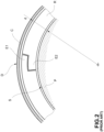
Fig. 5a and 5b are cross sections along a transverse plane of a piston according to a second embodiment of the invention in a first and a second operating condition, respectively; -
Fig. 6 is a cross section along a transverse plane of a piston according to a third embodiment of the invention; -
Fig. 7 is a cross section along a transverse plane of a piston according to a fourth embodiment of the invention; -
Fig. 8 is a cross section along a transverse plane of a piston according to a fifth embodiment of the invention; and -
Fig. 9 is a cross section along the plane D ofFig. 5a . - Before describing in detail a plurality of purely exemplifying embodiments of the invention, it should be clarified that the invention is not limited in its application to the construction details and to the configuration of the components presented in the following description or illustrated in the drawings. The invention may assume other embodiments and be implemented or constructed in practice in different ways. It should also be understood that the phraseology and terminology have a descriptive purpose and should not be construed as limiting. The use of "include" and "comprise" and their variations are to be understood as encompassing the elements set out below and their equivalents, as well as additional elements and the equivalents thereof.
- Throughout the present description and claims, terms and expressions indicating positions and orientations are to refer to their conventional meaning in the scope of a piston-cylinder mechanism. In particular: the term "axial" shall mean a direction extending along or parallel to the longitudinal axis of the piston and/or cylinder; the term "radial" shall mean a direction extending along a radius of the piston and/or cylinder and passing through the longitudinal axis of the same and/or a plane passing through the longitudinal axis of the piston and/or cylinder and a radius of the same; the term "transverse" shall mean a direction extending perpendicular to the longitudinal axis of the piston and/or cylinder and/or a plane perpendicular to the longitudinal axis of the piston and/or cylinder and on which a radius of the same lies.
- Referring initially to
Fig. 3 , a piston for compressing a pneumatic fluid in a cylinder C according to the invention is generally indicated with 10. - The
piston 10 essentially comprises apiston body 12 and asealing assembly 14. - The
piston body 12 is generally cylindrical in shape, and is arranged in use inside the cylinder C so as to be able to slide along an axial direction z for compressing a fluid in the cylinder C. Thepiston body 12 has aside wall 16, which in use faces an inner wall of the cylinder C, and atop wall 18, which in use defines, together with the cylinder C, a compression chamber CC. - Along the
side wall 16 of thepiston body 12, in particular along acircumferential perimeter 20 of theside wall 16, aseat 22 for accommodating thesealing assembly 14 is defined. - Furthermore, according to a preferable embodiment of the invention, the
piston body 12 comprises two parts, in particular afirst part 12a and asecond part 12b. Thefirst part 12a is comprised between thetop wall 18 of thepiston body 12 and theseat 22 thereof, while thesecond part 12b comprises the remaining part of thepiston body 12. Thefirst part 12a is preferably removable from thesecond part 12b, so as to facilitate the installation of thesealing assembly 14 within theseat 22. - With reference hereinafter also to
Fig. 4a to 8 , thesealing assembly 14 is housed in theseat 22 and is adapted to ensure the fluid-tightness of the compression chamber CC along saidcircumferential perimeter 20. Thesealing assembly 14 comprises a plurality ofsealing elements 24, which have shapes complementary to one another, and which are configured so that the wear of aparticular sealing element 24 along saidcircumferential perimeter 20 caused by the reciprocating compression movement of thepiston 10 corresponds to a sliding along a radially outer direction r of at least oneadjacent sealing element 24. - By way of non-limiting example, the
sealing elements 24 of thesealing group 14 are preferably made of a material based on carbon-filled polytetrafluoroethylene, or even more preferably boron nitride-filled, so as to be able to withstand the high temperatures to which they are subjected and, at the same time, ensure a low friction coefficient. -
Fig. 4a to 8 are different embodiments of thesealing elements 24. - In a first embodiment, in
Fig. 4a and 4b , thesealing assembly 14 comprises four sealing elements, in particular a pair offirst sealing elements 24 and a pair of second sealing elements 24'. Eachfirst sealing element 24 has, at least at a radially outer portion, a substantially triangular planform. Conversely, each second sealing element 24' has, at least at a radially outer portion, a substantially circular sector planform. As is clearly visible inFig. 4a and 4b , in this first embodiment thefirst sealing elements 24 and the second sealing elements 24' are arranged in contact with one another in pairs, and slidable relative to one another along planes A and B, which are non-radial and non-parallel to one another and arranged converging in a radially outer direction. The plane A and the plane B are, in effect, perpendicular to the transverse plane shown inFig. 4a and 4b but not parallel to, nor coinciding with, a radial plane. InFig. 4a thesealing assembly 14 is shown in a first operating condition, i.e., in an installation or initial condition. InFig. 4b , on the other hand, the sealingassembly 14 is shown in a second operating condition, wherein thefirst sealing elements 24 and the second sealing elements 24' have moved in a radially outer direction, since the compressed air contained in the compression chamber CC may pass into theseat 22 and slip between the sealingelements 24 and 24' as a result of wear. In this way, as the sealingelements 24 and 24' wear out, they are pushed in a radially outer direction ensuring the seal along thecircumferential perimeter 20. As is clearly seen inFig. 4b , while thepiston 10 slides inside the cylinder C, the radially outer portion of the sealingelements 24 and 24' jointly defines a continuous profile along saidcircumferential perimeter 20 in such a way as to maintain the fluid-tight seal of the compression chamber CC. In this first embodiment, the cross section of thepiston body 12 along a transverse plane at theseat 22 has substantially a cross shape with beveled corners; obviously both the length and the thickness of the arms of this cross may be made in dimensions and proportions different from those shown inFig. 4a and 4b . -
Fig. 5a and 5b show a second embodiment of the invention, under operating conditions similar to those described with respect toFig. 4a and 4b , respectively. This second embodiment differs from the first embodiment described due to the presence of four throughholes 26 on thetop wall 18 of thepiston body 12, adapted to put the compression chamber CC in fluid communication with theseat 22 to facilitate the passage of compressed air towards the radially inner area of theseat 22 and, therefore, pushing the first andsecond sealing elements 24 and 24' in a radially outer direction. Furthermore, in this second embodiment the first andsecond sealing elements 24 and 24' have slidingguides 28. The sliding guides 28 are arranged along respective contact surfaces 30 of the first andsecond sealing elements 24 and 24', and are configured so as to be coupled together and to allow the relative sliding of adjacent sealing elements. As shown inFig. 9 , the sliding guides 28 may be made by simple shape coupling; however, the sliding guides 28 may also be made in different configurations, or be replaced with other mechanisms adapted to facilitate the relative sliding of theadjacent sealing elements 24 and 24'. Also in this second embodiment, the cross section of thepiston body 12 at theseat 22 along a transverse plane has substantially a cross shape, with beveled corners, according to that which has already been described with respect to the first embodiment. -
Fig. 6 and7 show, respectively, a third and a fourth embodiment of the invention, which differ from the embodiments shown above only in the shape of the radially innermost portion of the sealingelements 24 and 24'. In effect, also in these embodiments, thefirst sealing elements 24 and the second sealing elements 24' are arranged in contact with one another in pairs, and slidable relative to one another along planes A and B, which are non-radial and non-parallel to one another and arranged converging in a radially outer direction. Moreover, also in these embodiments theadjacent sealing elements 24 and 24' are provided with slidingguides 28 adapted to facilitate the relative sliding. In the third embodiment, on thetop wall 18 of thepiston body 12, two throughholes 26 are formed, adapted to put the compression chamber CC in fluid communication with theseat 22 to facilitate the passage of compressed air towards the radially inner area of theseat 22 and thus to push the first andsecond sealing elements 24 and 24' in a radially outer direction. In the fourth embodiment, however, these holes are absent. In the third embodiment, as seen inFig. 6 , the cross section of thepiston body 12 at theseat 22 along a transverse plane has a substantially rectangular shape with beveled corners; obviously both the length and the thickness of the rectangular shape may be made in different dimensions and proportions than those shown inFig. 6 . In the fourth embodiment, however, as clearly visible inFig. 7 , the cross section of thepiston body 12 at theseat 22 along a transverse plane has a substantially circular shape, and, consequently, theseat 22 is ring-shaped. -
Fig. 8 shows a fifth embodiment of the invention, which differs from the embodiments described above by the presence of a greater number of sealing elements. In particular, in the fifth embodiment the sealingassembly 14 comprises fourfirst sealing elements 24 and four second sealing elements 24'. Eachfirst sealing element 24 has, at least at a radially outer portion, a substantially triangular planform. Conversely, each second sealing element 24' has, at least at a radially outer portion, a substantially circular sector planform. In the fifth embodiment, as is clearly visible inFig. 8 , the cross section of thepiston body 12 at theseat 22 along a transverse plane has substantially a cross shape, the corners of which may be beveled or not; obviously both the length and the thickness of the arms of this cross may be made in different dimensions and proportions than those shown inFig. 8 . - According to a preferable embodiment of the invention, at least one sealing
element 24 of the sealingassembly 14 has acheck hole 32 arranged so that, at a certain level of wear of this sealingelement 24, thecheck hole 32 puts the compression chamber CC in fluid communication with the rest of the cylinder C, so that the fluid-tightness of the compression chamber CC along thecircumferential perimeter 20 of theside wall 16 of thepiston body 12 is no longer ensured. In this way, it is possible for an operator to easily recognize the moment in which the wear of said sealingelement 24 has reached a predetermined level at which the replacement of the sealingelement 24 is necessary: in effect, when the wear is such that thecheck hole 32 puts the compression chamber CC in fluid communication with the rest of the cylinder C, the loss of pressure in the compression chamber CC will be evident to the operator. Thecheck hole 32 may be positioned at a specific radial distance as a function of the tolerable wear level for the sealingelement 24. - The
piston 10 according to the invention is particularly suitable for application in a reciprocating compressor, and in particular in a reciprocating compressor used in a railway vehicle. In a reciprocating compressor, maintaining the seal is necessary for correct operation, and the consequences of a deterioration of the seal vary from the simple reduction of the useful capacity of the compressor to seizure. - As is clear from the foregoing detailed description, the piston according to the invention has several advantages over the prior art.
- First of all, due to the configuration of the sealing unit, the piston according to the invention may ensure a better sealing and a longer duration of use. In effect, due to the greater thickness of the sealing elements with respect to conventional sealing rings, and due to the complementary arrangement of the sealing elements of the sealing assembly, the sealing assembly offers a greater quantity of consumable material, and, consequently, a longer time interval between replacement or maintenance.
- Moreover, due to the fact that the sealing elements are multiple and movable with one another, and particularly in the presence of at least one through hole on the top wall of the piston body to the seat, the seal of the sealing elements along the circumferential perimeter is improved by the fact that the pressurized air arriving from the compression chamber pushes the sealing elements in a radially outer direction in contact with the inner wall of the cylinder.
- Furthermore, due to the particular shapes assumed by the seat, it is possible to define a specific angular orientation of the sealing elements and, consequently, to distribute the loads according to the project in order to reduce the wear rate with respect to the weaker sealing elements.
- Lastly, in the presence of at least one check hole on at least one sealing element, the piston according to the invention allows the operator to determine easily and in time if the seal is still optimal or if the wear due to use requires maintenance.
- Various aspects and embodiments of a piston according to the invention have been described. It is understood that each embodiment may be combined with any other embodiment. Naturally, the invention is not limited to the embodiments described purely by way of example, but may be varied within the scope defined by the appended claims.
Claims (13)
- Piston (10) for the compression of a pneumatic fluid in a compression chamber (CC) of a cylinder (C) comprising:- a cylindrically shaped piston body (12), adapted to be arranged slidably within said cylinder (C), and having a side wall (16) and a top wall (18); along a circumferential perimeter (20) of said side wall (16) of the piston body (12) a seat (22) being defined; and- a sealing assembly (14) accommodated in said seat (22), and adapted to ensure the fluid-tightness along said circumferential perimeter (20);the piston being characterized in that,the sealing assembly (14) comprises a plurality of sealing elements (24, 24'), having shapes complementary to one another, and configured so that the wear of a sealing element (24, 24') along said circumferential perimeter (20) corresponds to a sliding in the radially outer direction of the adjacent sealing element (24', 24);in an operational condition wherein the piston (10) slides within the cylinder (C), the radially outer portion of the sealing elements (24, 24') jointly defines a continuous profile along said circumferential perimeter (20) in such a way to preserve the fluid-tightness.
- Piston according to claim 1, wherein adjacent sealing elements (24, 24') are arranged slidable to each other along a non-radial plane (A, B).
- Piston according to claim 2, wherein each sealing element (24) is arranged slidable relative to respective adjacent sealing elements (24') along planes (A, B) converging in a radially outer direction.
- Piston according to any of the preceding claims, wherein the sealing assembly (14) comprises at least:a first sealing element (24) having, at least at a radially outer portion, a substantially triangular planform; anda second sealing element (24'), adjacent to the first sealing element (24), having, at least at a radially outer portion, a planform substantially shaped as an annulus circular sector.
- Piston according to any of the preceding claims, further comprising at least one through hole (26) provided through the top wall (18) of the piston body (12) to said seat (22), so as to cause said sliding of a sealing element (24, 24') in a radially outer direction.
- Piston according to any of the preceding claims, wherein adjacent sealing elements (24, 24') have, along respective contact surfaces (30), respective sliding guides (28) configured to engage each other and to allow the relative sliding of the adjacent sealing elements (24, 24').
- Piston according to any of the preceding claims, wherein said seat (22) is ring-shaped.
- Piston according to any claim from 1 to 6, wherein said seat (22) is shaped so that the cross section of the piston body (12) at said seat (22) along a transverse plane has a substantially cross shape or a substantially rectangular shape, preferably with beveled corners.
- Piston according to any of the preceding claims, wherein said piston body (12) comprises two parts (12a, 12b), in particular a first part (12a), comprised between said top wall (18) of the piston body (12) and said seat (22) of the piston body (12), and a second part (12b) comprising the remaining part of the piston body (12), the first part (12a) being mounted detachably on the second part (12b).
- Piston according to any of the preceding claims, wherein at least one sealing element (24) has a through check hole (32), arranged in such a way that, at a certain level of wear of said sealing element (24), said check hole (32) is arranged to make sure the fluid-tightness along the circumferential perimeter (20) of the side wall (16) of the piston body (12) is no longer ensured.
- Piston according to any of the preceding claims, wherein the sealing elements (24, 24') of the sealing assembly (14) are made of a boron nitride-filled polytetrafluoroethylenebased material.
- Reciprocating compressor of a railway vehicle comprising a piston (10) according to any of the preceding claims, and a cylinder (C), wherein the piston body (12) is arranged slidably within said cylinder (C), and the top wall (18) of the piston body (12) is arranged so as to define jointly with said cylinder (C) a compression chamber (CC).
- Compressor according to claim 12, when dependent on claim 5, wherein said hole (26) is arranged to put said compression chamber (CC) in fluid communication with said seat (22).
Applications Claiming Priority (2)
| Application Number | Priority Date | Filing Date | Title |
|---|---|---|---|
| IT102019000014709A IT201900014709A1 (en) | 2019-08-13 | 2019-08-13 | Piston for reciprocating compressor with complementary sealing elements |
| PCT/IB2020/057533 WO2021028826A1 (en) | 2019-08-13 | 2020-08-11 | Piston for reciprocating compressor having complementary sealing elements |
Publications (2)
| Publication Number | Publication Date |
|---|---|
| EP4013963A1 EP4013963A1 (en) | 2022-06-22 |
| EP4013963B1 true EP4013963B1 (en) | 2024-04-24 |
Family
ID=69106043
Family Applications (1)
| Application Number | Title | Priority Date | Filing Date |
|---|---|---|---|
| EP20767875.6A Active EP4013963B1 (en) | 2019-08-13 | 2020-08-11 | Piston for reciprocating compressor having complementary sealing elements |
Country Status (7)
| Country | Link |
|---|---|
| US (1) | US11982265B2 (en) |
| EP (1) | EP4013963B1 (en) |
| CN (1) | CN114555944B (en) |
| ES (1) | ES2984128T3 (en) |
| HU (1) | HUE066504T2 (en) |
| IT (1) | IT201900014709A1 (en) |
| WO (1) | WO2021028826A1 (en) |
Families Citing this family (1)
| Publication number | Priority date | Publication date | Assignee | Title |
|---|---|---|---|---|
| JP7581284B2 (en) * | 2022-06-16 | 2024-11-12 | キヤノン株式会社 | Optical Instruments and Imaging Devices |
Citations (13)
| Publication number | Priority date | Publication date | Assignee | Title |
|---|---|---|---|---|
| GB249945A (en) | 1925-01-09 | 1926-04-08 | Alexander Garden Dunbar | Improvements in and relating to pistons |
| US2392182A (en) | 1943-06-19 | 1946-01-01 | Crane Packing Co | Piston construction |
| US2785029A (en) | 1954-08-23 | 1957-03-12 | Sealed Power Corp | Combination piston ring expander, side pressure spring and oil ventilator |
| US4570944A (en) | 1985-05-15 | 1986-02-18 | W. S. Shamban & Company | Seal assembly with reduced wear low pressure sealing ring |
| DE4238638A1 (en) | 1992-11-16 | 1994-05-19 | Robert Forwick | Hydraulic cylinder sealing - has two overlaid sealing rings within grooves round pistons to be pressed by hydraulic pressure against inner cylinder walls |
| WO1997019280A1 (en) | 1995-11-17 | 1997-05-29 | Maschinenfabrik Sulzer-Burckhardt Ag | Piston ring |
| EP1275888B1 (en) | 2001-07-09 | 2004-12-01 | Burckhardt Compression AG | Piston ring |
| US7811490B2 (en) | 2007-02-06 | 2010-10-12 | Garlock Sealing Technologies, Inc. | Boron nitride filled PTFE |
| WO2014064291A1 (en) | 2012-10-26 | 2014-05-01 | Burckhardt Compression Ag | Piston ring |
| CA2847760A1 (en) | 2014-03-28 | 2014-06-11 | Westport Power Inc. | Piston seal assembly with controlled leakage |
| EP2886583A1 (en) | 2013-12-17 | 2015-06-24 | Evonik Fibres GmbH | Polyimide powder having high thermooxidative stability |
| EP3246569A1 (en) | 2016-05-17 | 2017-11-22 | Compressor Products International LLC | Rod packing |
| WO2018108464A1 (en) | 2016-12-13 | 2018-06-21 | Burckhardt Compression Ag | Piston ring for a piston compressor, and piston compressor |
Family Cites Families (5)
| Publication number | Priority date | Publication date | Assignee | Title |
|---|---|---|---|---|
| US892978A (en) * | 1907-08-27 | 1908-07-14 | Charles William Carter | Metallic packing-ring. |
| DE2947895C2 (en) * | 1979-11-28 | 1982-03-18 | Hunger, Walter, 8700 Würzburg | Sealing arrangement in a floating piston |
| US20170082202A1 (en) * | 2015-09-17 | 2017-03-23 | Intellectual Property Holdings, Inc. | Seals for natural gas compressor |
| JP7307716B2 (en) * | 2017-08-09 | 2023-07-12 | メインスプリング エナジー, インコーポレイテッド | Piston seal ring assembly with gap cover element |
| US11047481B2 (en) | 2017-09-06 | 2021-06-29 | General Electric Company | Seal assembly for a rotary machine |
-
2019
- 2019-08-13 IT IT102019000014709A patent/IT201900014709A1/en unknown
-
2020
- 2020-08-11 CN CN202080071736.1A patent/CN114555944B/en active Active
- 2020-08-11 US US17/634,887 patent/US11982265B2/en active Active
- 2020-08-11 HU HUE20767875A patent/HUE066504T2/en unknown
- 2020-08-11 EP EP20767875.6A patent/EP4013963B1/en active Active
- 2020-08-11 ES ES20767875T patent/ES2984128T3/en active Active
- 2020-08-11 WO PCT/IB2020/057533 patent/WO2021028826A1/en not_active Ceased
Patent Citations (14)
| Publication number | Priority date | Publication date | Assignee | Title |
|---|---|---|---|---|
| GB249945A (en) | 1925-01-09 | 1926-04-08 | Alexander Garden Dunbar | Improvements in and relating to pistons |
| US2392182A (en) | 1943-06-19 | 1946-01-01 | Crane Packing Co | Piston construction |
| US2785029A (en) | 1954-08-23 | 1957-03-12 | Sealed Power Corp | Combination piston ring expander, side pressure spring and oil ventilator |
| US4570944A (en) | 1985-05-15 | 1986-02-18 | W. S. Shamban & Company | Seal assembly with reduced wear low pressure sealing ring |
| DE4238638A1 (en) | 1992-11-16 | 1994-05-19 | Robert Forwick | Hydraulic cylinder sealing - has two overlaid sealing rings within grooves round pistons to be pressed by hydraulic pressure against inner cylinder walls |
| EP0861391B1 (en) | 1995-11-17 | 2003-04-09 | Burckhardt Compression AG | Piston ring |
| WO1997019280A1 (en) | 1995-11-17 | 1997-05-29 | Maschinenfabrik Sulzer-Burckhardt Ag | Piston ring |
| EP1275888B1 (en) | 2001-07-09 | 2004-12-01 | Burckhardt Compression AG | Piston ring |
| US7811490B2 (en) | 2007-02-06 | 2010-10-12 | Garlock Sealing Technologies, Inc. | Boron nitride filled PTFE |
| WO2014064291A1 (en) | 2012-10-26 | 2014-05-01 | Burckhardt Compression Ag | Piston ring |
| EP2886583A1 (en) | 2013-12-17 | 2015-06-24 | Evonik Fibres GmbH | Polyimide powder having high thermooxidative stability |
| CA2847760A1 (en) | 2014-03-28 | 2014-06-11 | Westport Power Inc. | Piston seal assembly with controlled leakage |
| EP3246569A1 (en) | 2016-05-17 | 2017-11-22 | Compressor Products International LLC | Rod packing |
| WO2018108464A1 (en) | 2016-12-13 | 2018-06-21 | Burckhardt Compression Ag | Piston ring for a piston compressor, and piston compressor |
Non-Patent Citations (7)
| Title |
|---|
| ANONYMOUS: "REDURA® KOLBENDICHTSYSTEME - HETEROGENE SYSTEME FÜR GERINGSTE KOSTEN ÜBER DIE GESAMTE LEBENSDAUER", BURCKHARDT COMPRESSION, 15 July 2017 (2017-07-15), XP093256365 |
| D11 - DIRECTINDUSTRY: "Alle Kataloge und technischen Broschüren von Burckhardt Compression AG", 29 March 2015 (2015-03-29), Retrieved from the Internet <URL:https://pdf.directindustry.de/pdf/burckhardt-compression-ag-29022.html> [retrieved on 20250121] |
| D13 - KATALOG STASSKOL SKR 410002 |
| D13a - AUSZUG AUS KATALOG STASSKOL SKR 410002-DE GEMÄSS REV. 2 VOM 09.11.2007 |
| FEISTEL NORBERT: "EINFLUSS DER KOLBENRINGBAUFORM AUF DIE FÖRDERMENGE EINES TROCKEN LAUFENDEN WASSERSTOFFVERDICHTERS", BURCKHARDT COMPRESSION, 15 July 2017 (2017-07-15), XP093256362 |
| FEISTEL NORBERT: "Heterogen aufgebaute Dichtsysteme nach dem Redura Prinzip", BURCKHARDT COMPRESSION, 15 July 2017 (2017-07-15), pages 1 - 38, XP093256368 |
| FEISTEL NORBERT: "Zehn Jahre erfolgreicher Einsatz von TID-Kolbenringen ", BURCKHARDT COMPRESSION, vol. 16, no. 2, 15 June 2010 (2010-06-15), pages 1 - 406, XP093256360, DOI: 10.1016/j.jnucmat.2005.04.024 |
Also Published As
| Publication number | Publication date |
|---|---|
| ES2984128T3 (en) | 2024-10-29 |
| HUE066504T2 (en) | 2024-08-28 |
| WO2021028826A1 (en) | 2021-02-18 |
| EP4013963A1 (en) | 2022-06-22 |
| US11982265B2 (en) | 2024-05-14 |
| CN114555944A (en) | 2022-05-27 |
| IT201900014709A1 (en) | 2021-02-13 |
| CN114555944B (en) | 2024-07-09 |
| US20220325710A1 (en) | 2022-10-13 |
Similar Documents
| Publication | Publication Date | Title |
|---|---|---|
| US3653670A (en) | Spring-loaded seal with symmetrical cross section | |
| US4059280A (en) | Seal ring assembly | |
| EP3517807B1 (en) | Single seal ring stuffing box | |
| CN102252093B (en) | Fluid pressure apparatus | |
| US6340161B1 (en) | Machinery seal | |
| US20110283883A1 (en) | Fluid pressure apparatus | |
| US20100072712A1 (en) | Pressure packing comprised of packing rings secured against rotation with injection-molded segments | |
| GB2033537A (en) | Piston for pneumatic actuator | |
| US4289322A (en) | Gland pack for reciprocating machines operating at high pressure | |
| EP4013963B1 (en) | Piston for reciprocating compressor having complementary sealing elements | |
| US12209670B2 (en) | Piston ring for a piston compressor | |
| EP3246569B1 (en) | Rod packing | |
| US2707135A (en) | Cartridge seal | |
| US3443486A (en) | Piston and seal assembly | |
| KR20200123018A (en) | Annulr sealing assembly | |
| US3836158A (en) | Packing ring | |
| US20230332688A1 (en) | Throttle ring | |
| EP3096046B1 (en) | Abradable seal | |
| US3762729A (en) | Sealing rings | |
| US2847262A (en) | Sealing devices | |
| US2860936A (en) | Piston assembly | |
| US3233824A (en) | Multi-stage seal assembly | |
| US3173697A (en) | Piston assembly | |
| CN106931049A (en) | Clutch system and clutch control mechanism thereof | |
| US3756611A (en) | Packing retainer cup |
Legal Events
| Date | Code | Title | Description |
|---|---|---|---|
| STAA | Information on the status of an ep patent application or granted ep patent |
Free format text: STATUS: UNKNOWN |
|
| STAA | Information on the status of an ep patent application or granted ep patent |
Free format text: STATUS: THE INTERNATIONAL PUBLICATION HAS BEEN MADE |
|
| PUAI | Public reference made under article 153(3) epc to a published international application that has entered the european phase |
Free format text: ORIGINAL CODE: 0009012 |
|
| STAA | Information on the status of an ep patent application or granted ep patent |
Free format text: STATUS: REQUEST FOR EXAMINATION WAS MADE |
|
| 17P | Request for examination filed |
Effective date: 20220308 |
|
| AK | Designated contracting states |
Kind code of ref document: A1 Designated state(s): AL AT BE BG CH CY CZ DE DK EE ES FI FR GB GR HR HU IE IS IT LI LT LU LV MC MK MT NL NO PL PT RO RS SE SI SK SM TR |
|
| DAV | Request for validation of the european patent (deleted) | ||
| DAX | Request for extension of the european patent (deleted) | ||
| P01 | Opt-out of the competence of the unified patent court (upc) registered |
Effective date: 20230530 |
|
| GRAP | Despatch of communication of intention to grant a patent |
Free format text: ORIGINAL CODE: EPIDOSNIGR1 |
|
| STAA | Information on the status of an ep patent application or granted ep patent |
Free format text: STATUS: GRANT OF PATENT IS INTENDED |
|
| INTG | Intention to grant announced |
Effective date: 20231123 |
|
| GRAS | Grant fee paid |
Free format text: ORIGINAL CODE: EPIDOSNIGR3 |
|
| GRAA | (expected) grant |
Free format text: ORIGINAL CODE: 0009210 |
|
| STAA | Information on the status of an ep patent application or granted ep patent |
Free format text: STATUS: THE PATENT HAS BEEN GRANTED |
|
| AK | Designated contracting states |
Kind code of ref document: B1 Designated state(s): AL AT BE BG CH CY CZ DE DK EE ES FI FR GB GR HR HU IE IS IT LI LT LU LV MC MK MT NL NO PL PT RO RS SE SI SK SM TR |
|
| REG | Reference to a national code |
Ref country code: GB Ref legal event code: FG4D |
|
| REG | Reference to a national code |
Ref country code: CH Ref legal event code: EP |
|
| REG | Reference to a national code |
Ref country code: DE Ref legal event code: R096 Ref document number: 602020029663 Country of ref document: DE |
|
| REG | Reference to a national code |
Ref country code: IE Ref legal event code: FG4D |
|
| REG | Reference to a national code |
Ref country code: LT Ref legal event code: MG9D |
|
| REG | Reference to a national code |
Ref country code: NL Ref legal event code: MP Effective date: 20240424 Ref country code: HU Ref legal event code: AG4A Ref document number: E066504 Country of ref document: HU |
|
| REG | Reference to a national code |
Ref country code: AT Ref legal event code: MK05 Ref document number: 1679864 Country of ref document: AT Kind code of ref document: T Effective date: 20240424 |
|
| PG25 | Lapsed in a contracting state [announced via postgrant information from national office to epo] |
Ref country code: NL Free format text: LAPSE BECAUSE OF FAILURE TO SUBMIT A TRANSLATION OF THE DESCRIPTION OR TO PAY THE FEE WITHIN THE PRESCRIBED TIME-LIMIT Effective date: 20240424 |
|
| PG25 | Lapsed in a contracting state [announced via postgrant information from national office to epo] |
Ref country code: NL Free format text: LAPSE BECAUSE OF FAILURE TO SUBMIT A TRANSLATION OF THE DESCRIPTION OR TO PAY THE FEE WITHIN THE PRESCRIBED TIME-LIMIT Effective date: 20240424 |
|
| PG25 | Lapsed in a contracting state [announced via postgrant information from national office to epo] |
Ref country code: IS Free format text: LAPSE BECAUSE OF FAILURE TO SUBMIT A TRANSLATION OF THE DESCRIPTION OR TO PAY THE FEE WITHIN THE PRESCRIBED TIME-LIMIT Effective date: 20240824 |
|
| PG25 | Lapsed in a contracting state [announced via postgrant information from national office to epo] |
Ref country code: BG Free format text: LAPSE BECAUSE OF FAILURE TO SUBMIT A TRANSLATION OF THE DESCRIPTION OR TO PAY THE FEE WITHIN THE PRESCRIBED TIME-LIMIT Effective date: 20240424 |
|
| PG25 | Lapsed in a contracting state [announced via postgrant information from national office to epo] |
Ref country code: FI Free format text: LAPSE BECAUSE OF FAILURE TO SUBMIT A TRANSLATION OF THE DESCRIPTION OR TO PAY THE FEE WITHIN THE PRESCRIBED TIME-LIMIT Effective date: 20240424 Ref country code: HR Free format text: LAPSE BECAUSE OF FAILURE TO SUBMIT A TRANSLATION OF THE DESCRIPTION OR TO PAY THE FEE WITHIN THE PRESCRIBED TIME-LIMIT Effective date: 20240424 |
|
| PG25 | Lapsed in a contracting state [announced via postgrant information from national office to epo] |
Ref country code: GR Free format text: LAPSE BECAUSE OF FAILURE TO SUBMIT A TRANSLATION OF THE DESCRIPTION OR TO PAY THE FEE WITHIN THE PRESCRIBED TIME-LIMIT Effective date: 20240725 |
|
| PG25 | Lapsed in a contracting state [announced via postgrant information from national office to epo] |
Ref country code: PT Free format text: LAPSE BECAUSE OF FAILURE TO SUBMIT A TRANSLATION OF THE DESCRIPTION OR TO PAY THE FEE WITHIN THE PRESCRIBED TIME-LIMIT Effective date: 20240826 |
|
| PG25 | Lapsed in a contracting state [announced via postgrant information from national office to epo] |
Ref country code: AT Free format text: LAPSE BECAUSE OF FAILURE TO SUBMIT A TRANSLATION OF THE DESCRIPTION OR TO PAY THE FEE WITHIN THE PRESCRIBED TIME-LIMIT Effective date: 20240424 |
|
| PG25 | Lapsed in a contracting state [announced via postgrant information from national office to epo] |
Ref country code: PL Free format text: LAPSE BECAUSE OF FAILURE TO SUBMIT A TRANSLATION OF THE DESCRIPTION OR TO PAY THE FEE WITHIN THE PRESCRIBED TIME-LIMIT Effective date: 20240424 |
|
| REG | Reference to a national code |
Ref country code: ES Ref legal event code: FG2A Ref document number: 2984128 Country of ref document: ES Kind code of ref document: T3 Effective date: 20241029 |
|
| PG25 | Lapsed in a contracting state [announced via postgrant information from national office to epo] |
Ref country code: LV Free format text: LAPSE BECAUSE OF FAILURE TO SUBMIT A TRANSLATION OF THE DESCRIPTION OR TO PAY THE FEE WITHIN THE PRESCRIBED TIME-LIMIT Effective date: 20240424 |
|
| PG25 | Lapsed in a contracting state [announced via postgrant information from national office to epo] |
Ref country code: PT Free format text: LAPSE BECAUSE OF FAILURE TO SUBMIT A TRANSLATION OF THE DESCRIPTION OR TO PAY THE FEE WITHIN THE PRESCRIBED TIME-LIMIT Effective date: 20240826 Ref country code: PL Free format text: LAPSE BECAUSE OF FAILURE TO SUBMIT A TRANSLATION OF THE DESCRIPTION OR TO PAY THE FEE WITHIN THE PRESCRIBED TIME-LIMIT Effective date: 20240424 Ref country code: NO Free format text: LAPSE BECAUSE OF FAILURE TO SUBMIT A TRANSLATION OF THE DESCRIPTION OR TO PAY THE FEE WITHIN THE PRESCRIBED TIME-LIMIT Effective date: 20240724 Ref country code: LV Free format text: LAPSE BECAUSE OF FAILURE TO SUBMIT A TRANSLATION OF THE DESCRIPTION OR TO PAY THE FEE WITHIN THE PRESCRIBED TIME-LIMIT Effective date: 20240424 Ref country code: IS Free format text: LAPSE BECAUSE OF FAILURE TO SUBMIT A TRANSLATION OF THE DESCRIPTION OR TO PAY THE FEE WITHIN THE PRESCRIBED TIME-LIMIT Effective date: 20240824 Ref country code: HR Free format text: LAPSE BECAUSE OF FAILURE TO SUBMIT A TRANSLATION OF THE DESCRIPTION OR TO PAY THE FEE WITHIN THE PRESCRIBED TIME-LIMIT Effective date: 20240424 Ref country code: GR Free format text: LAPSE BECAUSE OF FAILURE TO SUBMIT A TRANSLATION OF THE DESCRIPTION OR TO PAY THE FEE WITHIN THE PRESCRIBED TIME-LIMIT Effective date: 20240725 Ref country code: FI Free format text: LAPSE BECAUSE OF FAILURE TO SUBMIT A TRANSLATION OF THE DESCRIPTION OR TO PAY THE FEE WITHIN THE PRESCRIBED TIME-LIMIT Effective date: 20240424 Ref country code: BG Free format text: LAPSE BECAUSE OF FAILURE TO SUBMIT A TRANSLATION OF THE DESCRIPTION OR TO PAY THE FEE WITHIN THE PRESCRIBED TIME-LIMIT Effective date: 20240424 Ref country code: AT Free format text: LAPSE BECAUSE OF FAILURE TO SUBMIT A TRANSLATION OF THE DESCRIPTION OR TO PAY THE FEE WITHIN THE PRESCRIBED TIME-LIMIT Effective date: 20240424 Ref country code: RS Free format text: LAPSE BECAUSE OF FAILURE TO SUBMIT A TRANSLATION OF THE DESCRIPTION OR TO PAY THE FEE WITHIN THE PRESCRIBED TIME-LIMIT Effective date: 20240724 |
|
| PG25 | Lapsed in a contracting state [announced via postgrant information from national office to epo] |
Ref country code: DK Free format text: LAPSE BECAUSE OF FAILURE TO SUBMIT A TRANSLATION OF THE DESCRIPTION OR TO PAY THE FEE WITHIN THE PRESCRIBED TIME-LIMIT Effective date: 20240424 |
|
| PG25 | Lapsed in a contracting state [announced via postgrant information from national office to epo] |
Ref country code: EE Free format text: LAPSE BECAUSE OF FAILURE TO SUBMIT A TRANSLATION OF THE DESCRIPTION OR TO PAY THE FEE WITHIN THE PRESCRIBED TIME-LIMIT Effective date: 20240424 |
|
| REG | Reference to a national code |
Ref country code: DE Ref legal event code: R026 Ref document number: 602020029663 Country of ref document: DE |
|
| PG25 | Lapsed in a contracting state [announced via postgrant information from national office to epo] |
Ref country code: CZ Free format text: LAPSE BECAUSE OF FAILURE TO SUBMIT A TRANSLATION OF THE DESCRIPTION OR TO PAY THE FEE WITHIN THE PRESCRIBED TIME-LIMIT Effective date: 20240424 |
|
| PLBI | Opposition filed |
Free format text: ORIGINAL CODE: 0009260 |
|
| PG25 | Lapsed in a contracting state [announced via postgrant information from national office to epo] |
Ref country code: RO Free format text: LAPSE BECAUSE OF FAILURE TO SUBMIT A TRANSLATION OF THE DESCRIPTION OR TO PAY THE FEE WITHIN THE PRESCRIBED TIME-LIMIT Effective date: 20240424 Ref country code: SK Free format text: LAPSE BECAUSE OF FAILURE TO SUBMIT A TRANSLATION OF THE DESCRIPTION OR TO PAY THE FEE WITHIN THE PRESCRIBED TIME-LIMIT Effective date: 20240424 |
|
| PG25 | Lapsed in a contracting state [announced via postgrant information from national office to epo] |
Ref country code: SM Free format text: LAPSE BECAUSE OF FAILURE TO SUBMIT A TRANSLATION OF THE DESCRIPTION OR TO PAY THE FEE WITHIN THE PRESCRIBED TIME-LIMIT Effective date: 20240424 |
|
| PG25 | Lapsed in a contracting state [announced via postgrant information from national office to epo] |
Ref country code: SM Free format text: LAPSE BECAUSE OF FAILURE TO SUBMIT A TRANSLATION OF THE DESCRIPTION OR TO PAY THE FEE WITHIN THE PRESCRIBED TIME-LIMIT Effective date: 20240424 Ref country code: SK Free format text: LAPSE BECAUSE OF FAILURE TO SUBMIT A TRANSLATION OF THE DESCRIPTION OR TO PAY THE FEE WITHIN THE PRESCRIBED TIME-LIMIT Effective date: 20240424 Ref country code: RO Free format text: LAPSE BECAUSE OF FAILURE TO SUBMIT A TRANSLATION OF THE DESCRIPTION OR TO PAY THE FEE WITHIN THE PRESCRIBED TIME-LIMIT Effective date: 20240424 Ref country code: EE Free format text: LAPSE BECAUSE OF FAILURE TO SUBMIT A TRANSLATION OF THE DESCRIPTION OR TO PAY THE FEE WITHIN THE PRESCRIBED TIME-LIMIT Effective date: 20240424 Ref country code: DK Free format text: LAPSE BECAUSE OF FAILURE TO SUBMIT A TRANSLATION OF THE DESCRIPTION OR TO PAY THE FEE WITHIN THE PRESCRIBED TIME-LIMIT Effective date: 20240424 Ref country code: CZ Free format text: LAPSE BECAUSE OF FAILURE TO SUBMIT A TRANSLATION OF THE DESCRIPTION OR TO PAY THE FEE WITHIN THE PRESCRIBED TIME-LIMIT Effective date: 20240424 |
|
| PLAB | Opposition data, opponent's data or that of the opponent's representative modified |
Free format text: ORIGINAL CODE: 0009299OPPO |
|
| PLBI | Opposition filed |
Free format text: ORIGINAL CODE: 0009260 |
|
| PLAX | Notice of opposition and request to file observation + time limit sent |
Free format text: ORIGINAL CODE: EPIDOSNOBS2 |
|
| 26 | Opposition filed |
Opponent name: KNORR-BREMSESYSTEME FUER SCHIENENFAHRZEUGE GMBH Effective date: 20250122 |
|
| 26 | Opposition filed |
Opponent name: BURCKHARDT COMPRESSION AG Effective date: 20250124 |
|
| R26 | Opposition filed (corrected) |
Opponent name: KNORR-BREMSESYSTEME FUER SCHIENENFAHRZEUGE GMBH Effective date: 20250122 |
|
| REG | Reference to a national code |
Ref country code: CH Ref legal event code: PL |
|
| PG25 | Lapsed in a contracting state [announced via postgrant information from national office to epo] |
Ref country code: LU Free format text: LAPSE BECAUSE OF NON-PAYMENT OF DUE FEES Effective date: 20240811 |
|
| PG25 | Lapsed in a contracting state [announced via postgrant information from national office to epo] |
Ref country code: SI Free format text: LAPSE BECAUSE OF FAILURE TO SUBMIT A TRANSLATION OF THE DESCRIPTION OR TO PAY THE FEE WITHIN THE PRESCRIBED TIME-LIMIT Effective date: 20240424 Ref country code: MC Free format text: LAPSE BECAUSE OF FAILURE TO SUBMIT A TRANSLATION OF THE DESCRIPTION OR TO PAY THE FEE WITHIN THE PRESCRIBED TIME-LIMIT Effective date: 20240424 Ref country code: CH Free format text: LAPSE BECAUSE OF NON-PAYMENT OF DUE FEES Effective date: 20240831 |
|
| PLAF | Information modified related to communication of a notice of opposition and request to file observations + time limit |
Free format text: ORIGINAL CODE: EPIDOSCOBS2 |
|
| PLBB | Reply of patent proprietor to notice(s) of opposition received |
Free format text: ORIGINAL CODE: EPIDOSNOBS3 |
|
| REG | Reference to a national code |
Ref country code: BE Ref legal event code: MM Effective date: 20240831 |
|
| PG25 | Lapsed in a contracting state [announced via postgrant information from national office to epo] |
Ref country code: BE Free format text: LAPSE BECAUSE OF NON-PAYMENT OF DUE FEES Effective date: 20240831 |
|
| PG25 | Lapsed in a contracting state [announced via postgrant information from national office to epo] |
Ref country code: IE Free format text: LAPSE BECAUSE OF NON-PAYMENT OF DUE FEES Effective date: 20240811 |
|
| PG25 | Lapsed in a contracting state [announced via postgrant information from national office to epo] |
Ref country code: SE Free format text: LAPSE BECAUSE OF FAILURE TO SUBMIT A TRANSLATION OF THE DESCRIPTION OR TO PAY THE FEE WITHIN THE PRESCRIBED TIME-LIMIT Effective date: 20240424 |
|
| PGFP | Annual fee paid to national office [announced via postgrant information from national office to epo] |
Ref country code: HU Payment date: 20250724 Year of fee payment: 6 |
|
| PGFP | Annual fee paid to national office [announced via postgrant information from national office to epo] |
Ref country code: ES Payment date: 20250911 Year of fee payment: 6 |
|
| PGFP | Annual fee paid to national office [announced via postgrant information from national office to epo] |
Ref country code: DE Payment date: 20250714 Year of fee payment: 6 |
|
| PGFP | Annual fee paid to national office [announced via postgrant information from national office to epo] |
Ref country code: GB Payment date: 20250717 Year of fee payment: 6 |
|
| PGFP | Annual fee paid to national office [announced via postgrant information from national office to epo] |
Ref country code: FR Payment date: 20250722 Year of fee payment: 6 |
|
| PG25 | Lapsed in a contracting state [announced via postgrant information from national office to epo] |
Ref country code: IT Free format text: LAPSE BECAUSE OF NON-PAYMENT OF DUE FEES Effective date: 20240811 |
|
| PG25 | Lapsed in a contracting state [announced via postgrant information from national office to epo] |
Ref country code: CY Free format text: LAPSE BECAUSE OF FAILURE TO SUBMIT A TRANSLATION OF THE DESCRIPTION OR TO PAY THE FEE WITHIN THE PRESCRIBED TIME-LIMIT; INVALID AB INITIO Effective date: 20200811 |