EP4013947B1 - Schätzung des bohrlochdrehmoments basierend auf richtungsmessungen - Google Patents
Schätzung des bohrlochdrehmoments basierend auf richtungsmessungen Download PDFInfo
- Publication number
- EP4013947B1 EP4013947B1 EP20854513.7A EP20854513A EP4013947B1 EP 4013947 B1 EP4013947 B1 EP 4013947B1 EP 20854513 A EP20854513 A EP 20854513A EP 4013947 B1 EP4013947 B1 EP 4013947B1
- Authority
- EP
- European Patent Office
- Prior art keywords
- angle
- toolface
- rotating
- static
- directional
- Prior art date
- Legal status (The legal status is an assumption and is not a legal conclusion. Google has not performed a legal analysis and makes no representation as to the accuracy of the status listed.)
- Active
Links
Images


Classifications
-
- E—FIXED CONSTRUCTIONS
- E21—EARTH OR ROCK DRILLING; MINING
- E21B—EARTH OR ROCK DRILLING; OBTAINING OIL, GAS, WATER, SOLUBLE OR MELTABLE MATERIALS OR A SLURRY OF MINERALS FROM WELLS
- E21B7/00—Special methods or apparatus for drilling
- E21B7/04—Directional drilling
- E21B7/06—Deflecting the direction of boreholes
- E21B7/067—Deflecting the direction of boreholes with means for locking sections of a pipe or of a guide for a shaft in angular relation, e.g. adjustable bent sub
-
- G—PHYSICS
- G01—MEASURING; TESTING
- G01L—MEASURING FORCE, STRESS, TORQUE, WORK, MECHANICAL POWER, MECHANICAL EFFICIENCY, OR FLUID PRESSURE
- G01L5/00—Apparatus for, or methods of, measuring force, work, mechanical power, or torque, specially adapted for specific purposes
-
- E—FIXED CONSTRUCTIONS
- E21—EARTH OR ROCK DRILLING; MINING
- E21B—EARTH OR ROCK DRILLING; OBTAINING OIL, GAS, WATER, SOLUBLE OR MELTABLE MATERIALS OR A SLURRY OF MINERALS FROM WELLS
- E21B44/00—Automatic control systems specially adapted for drilling operations, i.e. self-operating systems which function to carry out or modify a drilling operation without intervention of a human operator, e.g. computer-controlled drilling systems; Systems specially adapted for monitoring a plurality of drilling variables or conditions
- E21B44/02—Automatic control of the tool feed
- E21B44/04—Automatic control of the tool feed in response to the torque of the drive ; Measuring drilling torque
-
- E—FIXED CONSTRUCTIONS
- E21—EARTH OR ROCK DRILLING; MINING
- E21B—EARTH OR ROCK DRILLING; OBTAINING OIL, GAS, WATER, SOLUBLE OR MELTABLE MATERIALS OR A SLURRY OF MINERALS FROM WELLS
- E21B47/00—Survey of boreholes or wells
- E21B47/007—Measuring stresses in a pipe string or casing
-
- E—FIXED CONSTRUCTIONS
- E21—EARTH OR ROCK DRILLING; MINING
- E21B—EARTH OR ROCK DRILLING; OBTAINING OIL, GAS, WATER, SOLUBLE OR MELTABLE MATERIALS OR A SLURRY OF MINERALS FROM WELLS
- E21B47/00—Survey of boreholes or wells
- E21B47/02—Determining slope or direction
- E21B47/024—Determining slope or direction of devices in the borehole
-
- E—FIXED CONSTRUCTIONS
- E21—EARTH OR ROCK DRILLING; MINING
- E21B—EARTH OR ROCK DRILLING; OBTAINING OIL, GAS, WATER, SOLUBLE OR MELTABLE MATERIALS OR A SLURRY OF MINERALS FROM WELLS
- E21B7/00—Special methods or apparatus for drilling
- E21B7/04—Directional drilling
Definitions
- the system 10 includes a conventional derrick 14 that supports a rotary table 16 that is rotated at a desired rotational speed.
- the drill string 11 includes one or more drill pipe sections 18 that extend downward into the borehole 12 from the rotary table 16, and are connected to a drilling assembly 20.
- Drilling fluid or drilling mud 22 is pumped through the drill string 11 and/or the borehole 12.
- the well drilling system 10 also includes a bottomhole assembly (BHA) 24.
- BHA bottomhole assembly
- the drilling assembly 20 is included in the bottomhole assembly (BHA) 24, which is disposable within the system 10 at or near the downhole portion of the drill string 11.
- BHA bottomhole assembly
- the system 10 includes any number of downhole tools 32 for various processes including formation drilling, geosteering, and formation evaluation (FE) for measuring versus depth and/or time one or more physical quantities in or around a borehole.
- the tool 32 may be included in or embodied as a BHA, drill string component or other suitable carrier.
- These sensors 34 may include formation evaluation sensors (e.g., resistivity, dielectric constant, water saturation, porosity, density and permeability), sensors for measuring borehole parameters (e.g., borehole size, and borehole roughness), sensors for measuring geophysical parameters (e.g., acoustic velocity and acoustic travel time), sensors for measuring borehole fluid parameters (e.g., viscosity, density, clarity, rheology, pH level, and gas, oil and water contents), boundary condition sensors, and sensors for measuring physical and chemical properties of the borehole fluid.
- formation evaluation sensors e.g., resistivity, dielectric constant, water saturation, porosity, density and permeability
- sensors for measuring borehole parameters e.g., borehole size, and borehole roughness
- sensors for measuring geophysical parameters e.g., acoustic velocity and acoustic travel time
- sensors for measuring borehole fluid parameters e.g., viscosity, density, clarity, rheology, pH level, and gas
- the system 10 also includes a directional measurement assembly that includes two or more sets of directional sensors 35 that are located at various axial locations along the drill string 11, the BHA 24 and/or any other downhole component or components.
- Each set of directional sensors 35 includes one or more directional sensors configured to take directional measurements at corresponding axial locations.
- a "directional measurement” is a measurement of a parameter or property indicative of, or usable to estimate, a directional property of the downhole component. Examples of directional sensors include magnetometers, accelerometers, gyroscopes and others.
- Directional measurements are typically utilized in directional drilling operations to estimate directional properties of a downhole component, such as toolface, azimuth and inclination.
- the parameter sensors 34, the sets of directional sensors 35 and/or other downhole components include and/or are configured to communicate with a processor to receive, measure and/or estimate directional and other characteristics of the downhole components, borehole and/or the formation.
- the sensors 34, sets of directional sensors 35 and/or BHA 24 are equipped with transmission equipment to communicate with a processor such as a surface processing unit 36 and/or a downhole processor 38.
- the directional measurement assembly is part of a torque estimation system that includes a processing device (e.g., the surface processing unit 36 and/or downhole processor 38) configured to acquire or receive directional measurement data.
- the processing device estimates torque on a downhole component based on directional measurements and mechanical properties of the downhole component.
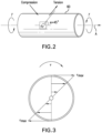
- Figures 2 and 3 show an example of a downhole component 50, and torque distribution during drilling.
- the downhole component 50 is a tubular such as a drill collar, which has a rotation axis A. It is noted that the downhole component is not limited to this example.
- the downhole component 50 is in torsion and experiences torque T in opposing rotational directions.
- the torque T at a selected axial location is shown in Figure 3 , which illustrates the distribution of torsional shear stress ⁇ .
- the magnitude of the shear stress increases radially from zero at the center of the downhole component 50 to a maximum shear stress ⁇ max at the surface of the downhole component 50.
- the torque estimation system utilizes directional measurements taken at different axial locations.
- the directional measurements are used to calculate the torque at a selected axial location and/or a distribution of torque along an axial length L of a downhole component.
- An "axial" location refers to a location on a downhole component relative to a longitudinal axis and/or axis of rotation of a component.
- a processing device is configured to determine the difference between the orientation of a first set of directional sensors and the orientation of a second set of directional sensors, which can change over time due to, for example, high frequency changes in the torque downhole.
- the processing device estimates the downhole torque based on the difference between orientations and one or more mechanical properties of the downhole component.
- the downhole torque is estimated by calculating an angle of torsion between the axial locations.
- the angle of torsion is then converted to downhole torque using material properties of the downhole component and offset corrections based on the relative orientation of directional sensors along the downhole component and/or string 12.
- the torque estimation system can use any of a variety of types of sensors and/or directional measurements.
- the sets of directional sensors include accelerometers and/or magnetometers.
- the torque estimation system estimates the angle of torsion ⁇ between a first axial location and a second axial location.
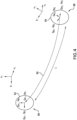
- Figure 4 illustrates a section of a downhole component 60 having a length L that extends from a first axial location 62 to a second axial location 64.
- a set of directional sensors are disposed at each axial location 62 and 64.
- Each set of directional sensors has an orientation relative to the downhole component longitudinal axis. This orientation is referred to as the "toolface orientation,” the "toolface angle” or simply “toolface.”
- two sets of directional sensors are disposed on the downhole component 60.
- a first set 66 of directional sensors is disposed at the first axial location 62
- a second set 68 of directional sensors In this embodiment, the first set 66 and the second set 68 each include a three-axis accelerometer and a three-axis magnetometer.
- Each set of sensors is configured to take a directional measurement in the directions of three orthogonal axes.
- the first set 66 includes sensor components oriented along axes x 1 , y 1 and z 1 , which define a first coordinate system.
- the second set 68 includes sensor components oriented along axes x 2 , y 2 and z 2 , which define a second coordinate system.
- the sets 66 and 68 are separated by the distance L. It is noted that the coordinate systems are specific to each set of sensors, so that rotation of one set relative to the other results in the sets having differently oriented axes.
- the first set 66 of sensors outputs a first set of measurement data that includes accelerometer measurements Gxl, Gy1, Gz1, and magnetometer measurements Hx1, Hy1, Hz1.
- the second set of sensors outputs a second set of measurement data that includes accelerometer measurements Gx2, Gy2 and Gz2, and magnetometer measurements Hx2, Hy2 and Hz2.
- T ⁇ G ⁇ 64 d out 4 ⁇ d in 4 L .
- L is the distance between the sets 66 and 68, which does not substantially change during rotation (e.g., during a drilling run).
- the internal and external diameters can also be assumed constant for a given component size. Based on the assumptions that the length L and the diameters do not change, the remaining variable in equation (3) is the angle of torsion ⁇ .
- the angle of torsion is calculated based on a toolface offset between the sets of sensors.
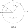
- the "toolface offset” refers to an angular difference between the toolface of the first set 66 of sensors and the toolface of the second set 68 of sensors.
- Figure 5 is a projection of the first and second axial locations onto single plane to show the relative orientations of directional measurements.
Landscapes
- Geology (AREA)
- Life Sciences & Earth Sciences (AREA)
- Engineering & Computer Science (AREA)
- Mining & Mineral Resources (AREA)
- Physics & Mathematics (AREA)
- Environmental & Geological Engineering (AREA)
- Fluid Mechanics (AREA)
- General Life Sciences & Earth Sciences (AREA)
- Geochemistry & Mineralogy (AREA)
- Geophysics (AREA)
- General Physics & Mathematics (AREA)
- Force Measurement Appropriate To Specific Purposes (AREA)
- Testing Of Devices, Machine Parts, Or Other Structures Thereof (AREA)
Claims (15)
- Verfahren (100) zum Schätzen von Drehmoment, umfassend:Anordnen mindestens einer Messbaugruppe an einer Bohrlochkomponente (50, 60), die mindestens eine Messbaugruppe einschließlich eines ersten Satzes von Richtungssensoren (66), die an einer ersten axialen Position (62) entlang der Bohrlochkomponente (50, 60) angeordnet sind, und eines zweiten Satzes von Richtungssensoren (68), die an einer zweiten axialen Position (64) entlang der Bohrlochkomponente (50, 60) angeordnet sind;Sammeln von Richtungsmessdaten von dem ersten Satz von Richtungssensoren (66) und von dem zweiten Satz von Richtungssensoren (68) während einer Drehung der Bohrlochkomponente (50, 60); undSchätzen, durch eine Verarbeitungsvorrichtung (36,38), eines Drehmomentbetrags auf die Bohrlochkomponente (50, 60) basierend auf den Richtungsmessdaten;wobei das Schätzen des Drehmomentbetrags ein Berechnen eines Torsionswinkels basierend auf einem berechneten Winkel zwischen einer Ausrichtung des ersten Satzes von Richtungssensoren (66) und einer Ausrichtung des zweiten Satzes von Richtungssensoren (68) einschließt;dadurch gekennzeichnet, dass:
das Sammeln der Richtungsmessdaten ein Messen eines ersten Winkels einer statischen Werkzeugfläche des ersten Satzes von Richtungssensoren (66) und eines zweiten Winkels der statischen Werkzeugfläche des zweiten Satzes von Richtungssensoren (68), wenn die Bohrlochkomponente (50, 60) drehfest ist, einschließt, und das Schätzen des Drehmomentbetrags das Berechnen eines Versatzwinkels der statischen Werkzeugfläche basierend auf einer Differenz zwischen dem ersten Winkel der statischen Werkzeugfläche und dem zweiten Winkel der statischen Werkzeugfläche einschließt. - Verfahren (100) nach Anspruch 1, wobei der erste Satz von Richtungssensoren (66) und der zweite Satz von Richtungssensoren (68) jeder mindestens eines von einem Magnetometer und einen Beschleunigungsmesser einschließen.
- Verfahren (100) nach einem der vorstehenden Ansprüche, wobei das Sammeln der Richtungsmessdaten das Messen eines ersten Winkels einer sich drehenden Werkzeugfläche und eines zweiten Winkels der sich drehenden Werkzeugfläche, wenn sich die Bohrlochkomponente (50, 60) dreht, einschließt, und das Schätzen des Drehmomentbetrags das Berechnen eines Versatzwinkels der sich drehenden Werkzeugfläche basierend auf einer Differenz zwischen dem ersten Winkel der sich drehenden Werkzeugfläche und dem zweiten Winkel der sich drehenden Werkzeugfläche einschließt.
- Verfahren (100) nach Anspruch 3, wobei der Torsionswinkel basierend auf dem Winkel der statischen Werkzeugfläche und dem Winkel der sich drehenden Werkzeugfläche berechnet wird.
- Verfahren (100) nach Anspruch 3 oder 4, wobei der erste Satz von Richtungssensoren (66) und der zweite Satz von Richtungssensoren (68) jeder ein Magnetometer einschließen und der Versatzwinkel der statischen Werkzeugfläche ein Versatzwinkel einer statischen magnetischen Werkzeugfläche ist und der Versatzwinkel der sich drehenden Werkzeugfläche der Versatzwinkel einer sich drehenden magnetischen Werkzeugfläche ist.
- Verfahren (100) nach einem der Ansprüche 3 bis 5, wobei der erste Satz von Richtungssensoren (66) und der zweite Satz von Richtungssensoren (68) jeder einen Beschleunigungsmesser einschließen und der Versatzwinkel der statischen Werkzeugfläche ein Versatzwinkel einer statischen Schwere-Werkzeugfläche ist und der Versatzwinkel der sich drehenden Werkzeugfläche der Versatzwinkel einer sich drehenden Schwere-Werkzeugfläche ist.
- Verfahren (100) nach einem der Ansprüche 3 bis 6, wobei mindestens einer von dem Winkel der statischen Werkzeugfläche und dem Winkel der sich drehenden Werkzeugfläche basierend auf einem Torsionsmodell der Bohrlochkomponente (50, 60) berechnet werden, wobei das Torsionsmodell auf Eigenschaften der Bohrlochkomponente (50, 60) einschließlich geometrischer Eigenschaften, Trägheitsmoment und Schermodul basiert.
- Verfahren (100) nach einem der Ansprüche 3 bis 7, wobei mindestens eine von der statischen Werkzeugfläche und der sich drehenden Werkzeugfläche basierend auf einem Zustandsschätzungsalgorithmus berechnet wird.
- System (10) zum Schätzen von Drehmoment, das System umfassend:eine Messbaugruppe an einer Bohrlochkomponente (50, 60), die konfiguriert ist, um in einem Bohrloch (12) angeordnet zu werden, die Messbaugruppe einschließlich eines ersten Satzes von Richtungssensoren (66), die an einer ersten axialen Position (62) entlang der Bohrlochkomponente (50, 60) angeordnet sind, und eines zweiten Satzes von Richtungssensoren (68), die an einer zweiten axialen Position (64) entlang der Bohrlochkomponente (50, 60) angeordnet sind; undeine Verarbeitungsvorrichtung (36,38), die konfiguriert ist zum Durchführen von:dadurch gekennzeichnet, dass:Sammeln von Richtungsmessdaten von dem ersten Satz von Richtungssensoren (66) und von dem zweiten Satz von Richtungssensoren (68) während der Drehung der Bohrlochkomponente (50, 60); undSchätzen eines Drehmomentbetrags auf die Bohrlochkomponente (50, 60) basierend auf den Richtungsmessdaten;wobei das Schätzen des Drehmomentbetrags das Berechnen eines Torsionswinkels basierend auf einem berechneten Winkel zwischen einer Ausrichtung des ersten Satzes von Richtungssensoren (66) und einer Ausrichtung des zweiten Satzes von Richtungssensoren (68) einschließt;
das Sammeln der Richtungsmessdaten das Messen eines ersten Winkels der statischen Werkzeugfläche des ersten Satzes von Richtungssensoren (66) und eines zweiten Winkels der statischen Werkzeugfläche des zweiten Satzes von Richtungssensoren (68), wenn die Bohrlochkomponente (50, 60) drehfest ist, einschließt, und das Schätzen des Drehmomentbetrags das Berechnen eines Versatzwinkels der statischen Werkzeugfläche basierend auf einer Differenz zwischen dem ersten Winkel der statischen Werkzeugfläche und dem zweiten Winkel der statischen Werkzeugfläche einschließt. - System (10) nach Anspruch 9, wobei der erste Satz von Richtungssensoren (66) und der zweite Satz von Richtungssensoren (68) jeder mindestens eines von einem Magnetometer und einen Beschleunigungsmesser einschließen.
- System (10) nach einem der Ansprüche 9 oder 10, wobei das Sammeln der Richtungsmessdaten das Messen eines ersten Winkels der sich drehenden Werkzeugfläche und eines zweiten Winkels der sich drehenden Werkzeugfläche, wenn sich die Bohrlochkomponente (50, 60) dreht, einschließt, und das Schätzen des Drehmomentbetrags das Berechnen eines Versatzwinkels der sich drehenden Werkzeugfläche basierend auf einer Differenz zwischen dem ersten Winkel der sich drehenden Werkzeugfläche und dem zweiten Winkel der sich drehenden Werkzeugfläche einschließt.
- System (10) nach Anspruch 11, wobei der Torsionswinkel basierend auf dem Winkel der statischen Werkzeugfläche und dem Winkel der sich drehenden Werkzeugfläche berechnet wird.
- System (10) nach Anspruch 11 oder 12, wobei der erste Satz von Richtungssensoren und der zweite Satz von Richtungssensoren jeder ein Magnetometer einschließen und der Versatzwinkel der statischen Werkzeugfläche ein Versatzwinkel der statischen magnetischen Werkzeugfläche ist und ein Versatzwinkel der sich drehenden Werkzeugfläche ein Versatzwinkel der sich drehenden magnetischen Werkzeugfläche ist.
- System (10) nach einem der Ansprüche 11 bis 13, wobei der erste Satz von Richtungssensoren und der zweite Satz von Richtungssensoren jeder einen Beschleunigungsmesser einschließen und der Versatzwinkel der statischen Werkzeugfläche ein Versatzwinkel der statischen Schwere-Werkzeugfläche ist und der Versatzwinkel der sich drehenden Werkzeugfläche ein Versatzwinkel der sich drehenden Schwere-Werkzeugfläche ist.
- System (10) nach einem der Ansprüche 11 bis 14, wobei die Verarbeitungsvorrichtung konfiguriert ist zum:Berechnen mindestens eines von dem Winkel der statischen Werkzeugfläche und dem Winkel der sich drehenden Werkzeugfläche basierend auf einem Torsionsmodell der Bohrlochkomponente, wobei das Torsionsmodell auf Eigenschaften der Bohrlochkomponente einschließlich geometrischer Eigenschaften, Trägheitsmoment und Schermodul basiert; und/oderBerechnen mindestens eines von dem Winkel der statischen Werkzeugfläche und dem Winkel der sich drehenden Werkzeugfläche basierend auf einem Zustandsschätzungsalgorithmus.
Applications Claiming Priority (2)
| Application Number | Priority Date | Filing Date | Title |
|---|---|---|---|
| US16/542,520 US11573139B2 (en) | 2019-08-16 | 2019-08-16 | Estimation of downhole torque based on directional measurements |
| PCT/US2020/046067 WO2021034584A1 (en) | 2019-08-16 | 2020-08-13 | Estimation of downhole torque based on directional measurements |
Publications (3)
| Publication Number | Publication Date |
|---|---|
| EP4013947A1 EP4013947A1 (de) | 2022-06-22 |
| EP4013947A4 EP4013947A4 (de) | 2023-08-09 |
| EP4013947B1 true EP4013947B1 (de) | 2025-07-09 |
Family
ID=74566708
Family Applications (1)
| Application Number | Title | Priority Date | Filing Date |
|---|---|---|---|
| EP20854513.7A Active EP4013947B1 (de) | 2019-08-16 | 2020-08-13 | Schätzung des bohrlochdrehmoments basierend auf richtungsmessungen |
Country Status (4)
| Country | Link |
|---|---|
| US (1) | US11573139B2 (de) |
| EP (1) | EP4013947B1 (de) |
| SA (1) | SA522431648B1 (de) |
| WO (1) | WO2021034584A1 (de) |
Families Citing this family (4)
| Publication number | Priority date | Publication date | Assignee | Title |
|---|---|---|---|---|
| US12168925B2 (en) * | 2021-09-30 | 2024-12-17 | Nabors Drilling Technologies Usa, Inc. | Gravity toolface for wellbores |
| GB2629970B (en) * | 2022-01-21 | 2025-05-07 | Baker Hughes Oilfield Operations Llc | Processing of directional survey data recorded during rotational drilling |
| US12435617B2 (en) * | 2023-06-12 | 2025-10-07 | Baker Hughes Oilfield Operations Llc | Measuring torque using shaft twist in electric submersible pumping system motors |
| CN119738076B (zh) * | 2024-11-29 | 2025-09-19 | 中国地质大学(北京) | 一种井下钻压和扭矩测量方法及系统 |
Family Cites Families (10)
| Publication number | Priority date | Publication date | Assignee | Title |
|---|---|---|---|---|
| US4351027A (en) | 1980-08-13 | 1982-09-21 | Honeywell Inc. | Adaptive riser angle position reference system |
| US7000700B2 (en) | 2002-07-30 | 2006-02-21 | Baker Hughes Incorporated | Measurement-while-drilling assembly using real-time toolface oriented measurements |
| US7414405B2 (en) * | 2005-08-02 | 2008-08-19 | Pathfinder Energy Services, Inc. | Measurement tool for obtaining tool face on a rotating drill collar |
| US10480304B2 (en) | 2011-10-14 | 2019-11-19 | Weatherford Technology Holdings, Llc | Analysis of drillstring dynamics using an angular rate sensor |
| US9429008B2 (en) * | 2013-03-15 | 2016-08-30 | Smith International, Inc. | Measuring torque in a downhole environment |
| US9850712B2 (en) | 2013-12-12 | 2017-12-26 | Schlumberger Technology Corporation | Determining drilling state for trajectory control |
| CN105899757A (zh) * | 2013-12-17 | 2016-08-24 | 哈利伯顿能源服务公司 | 包括钻柱伸长和扭转的估计的钻井模型校准 |
| US9404307B2 (en) * | 2014-06-02 | 2016-08-02 | Schlumberger Technology Corporation | Method and system for directional drilling |
| US10415363B2 (en) * | 2016-09-30 | 2019-09-17 | Weatherford Technology Holdings, Llc | Control for rotary steerable system |
| EP3585977B1 (de) | 2017-02-22 | 2026-04-01 | Evolution Engineering Inc. | Automatisierte bohrverfahren und -systeme mit echtzeitanalyse der bohrstrangdynamik |
-
2019
- 2019-08-16 US US16/542,520 patent/US11573139B2/en active Active
-
2020
- 2020-08-13 EP EP20854513.7A patent/EP4013947B1/de active Active
- 2020-08-13 WO PCT/US2020/046067 patent/WO2021034584A1/en not_active Ceased
-
2022
- 2022-02-10 SA SA522431648A patent/SA522431648B1/ar unknown
Also Published As
| Publication number | Publication date |
|---|---|
| SA522431648B1 (ar) | 2024-02-29 |
| WO2021034584A1 (en) | 2021-02-25 |
| EP4013947A1 (de) | 2022-06-22 |
| US11573139B2 (en) | 2023-02-07 |
| EP4013947A4 (de) | 2023-08-09 |
| US20210048357A1 (en) | 2021-02-18 |
Similar Documents
| Publication | Publication Date | Title |
|---|---|---|
| EP3585977B1 (de) | Automatisierte bohrverfahren und -systeme mit echtzeitanalyse der bohrstrangdynamik | |
| AU2014415573B2 (en) | Continuous locating while drilling | |
| EP2929141B1 (de) | Gewichtungsfunktion zur neigungs- und azimut-berechnung | |
| CN112154253B (zh) | 独立于传感器位置而估计钻井系统中的最大负荷振幅 | |
| US12153185B2 (en) | Azimuthal measurement for geosteering | |
| CA2890150C (en) | Passive magnetic ranging for sagd and relief wells via a linearized trailing window kalman filter | |
| EP3436660B1 (de) | Operative modalanalyse in einem bohrloch | |
| US11573139B2 (en) | Estimation of downhole torque based on directional measurements | |
| EP3559411B1 (de) | Erweiterung des bereichs eines mems-gyroskops mittels exzentrischer beschleunigungsmesser | |
| US20130124095A1 (en) | Downhole dynamics measurements using rotating navigation sensors | |
| US12065922B2 (en) | Estimation of maximum load amplitudes in drilling systems using multiple independent measurements | |
| US20170370152A1 (en) | Dogleg Severity Estimator for Point-The-Bit Rotary Steerable Systems | |
| WO2019118167A1 (en) | Methods and systems azimuthal locking for drilling operations | |
| AU2021467204B2 (en) | Drilling system with directional survey transmission system and methods of transmission | |
| GB2603081A (en) | Azimuth determination while rotating |
Legal Events
| Date | Code | Title | Description |
|---|---|---|---|
| STAA | Information on the status of an ep patent application or granted ep patent |
Free format text: STATUS: THE INTERNATIONAL PUBLICATION HAS BEEN MADE |
|
| PUAI | Public reference made under article 153(3) epc to a published international application that has entered the european phase |
Free format text: ORIGINAL CODE: 0009012 |
|
| STAA | Information on the status of an ep patent application or granted ep patent |
Free format text: STATUS: REQUEST FOR EXAMINATION WAS MADE |
|
| 17P | Request for examination filed |
Effective date: 20220224 |
|
| AK | Designated contracting states |
Kind code of ref document: A1 Designated state(s): AL AT BE BG CH CY CZ DE DK EE ES FI FR GB GR HR HU IE IS IT LI LT LU LV MC MK MT NL NO PL PT RO RS SE SI SK SM TR |
|
| DAV | Request for validation of the european patent (deleted) | ||
| DAX | Request for extension of the european patent (deleted) | ||
| P01 | Opt-out of the competence of the unified patent court (upc) registered |
Effective date: 20230526 |
|
| A4 | Supplementary search report drawn up and despatched |
Effective date: 20230711 |
|
| RIC1 | Information provided on ipc code assigned before grant |
Ipc: E21B 47/26 20120101ALI20230705BHEP Ipc: E21B 47/0228 20120101AFI20230705BHEP |
|
| GRAP | Despatch of communication of intention to grant a patent |
Free format text: ORIGINAL CODE: EPIDOSNIGR1 |
|
| STAA | Information on the status of an ep patent application or granted ep patent |
Free format text: STATUS: GRANT OF PATENT IS INTENDED |
|
| INTG | Intention to grant announced |
Effective date: 20250414 |
|
| GRAS | Grant fee paid |
Free format text: ORIGINAL CODE: EPIDOSNIGR3 |
|
| GRAA | (expected) grant |
Free format text: ORIGINAL CODE: 0009210 |
|
| STAA | Information on the status of an ep patent application or granted ep patent |
Free format text: STATUS: THE PATENT HAS BEEN GRANTED |
|
| AK | Designated contracting states |
Kind code of ref document: B1 Designated state(s): AL AT BE BG CH CY CZ DE DK EE ES FI FR GB GR HR HU IE IS IT LI LT LU LV MC MK MT NL NO PL PT RO RS SE SI SK SM TR |
|
| REG | Reference to a national code |
Ref country code: GB Ref legal event code: FG4D |
|
| REG | Reference to a national code |
Ref country code: CH Ref legal event code: EP |
|
| REG | Reference to a national code |
Ref country code: IE Ref legal event code: FG4D |
|
| REG | Reference to a national code |
Ref country code: DE Ref legal event code: R096 Ref document number: 602020054343 Country of ref document: DE |
|
| PGFP | Annual fee paid to national office [announced via postgrant information from national office to epo] |
Ref country code: NO Payment date: 20250825 Year of fee payment: 6 |
|
| PGFP | Annual fee paid to national office [announced via postgrant information from national office to epo] |
Ref country code: GB Payment date: 20250822 Year of fee payment: 6 |
|
| REG | Reference to a national code |
Ref country code: NL Ref legal event code: MP Effective date: 20250709 |
|
| PG25 | Lapsed in a contracting state [announced via postgrant information from national office to epo] |
Ref country code: PT Free format text: LAPSE BECAUSE OF FAILURE TO SUBMIT A TRANSLATION OF THE DESCRIPTION OR TO PAY THE FEE WITHIN THE PRESCRIBED TIME-LIMIT Effective date: 20251110 |
|
| PG25 | Lapsed in a contracting state [announced via postgrant information from national office to epo] |
Ref country code: NL Free format text: LAPSE BECAUSE OF FAILURE TO SUBMIT A TRANSLATION OF THE DESCRIPTION OR TO PAY THE FEE WITHIN THE PRESCRIBED TIME-LIMIT Effective date: 20250709 |
|
| REG | Reference to a national code |
Ref country code: AT Ref legal event code: MK05 Ref document number: 1811997 Country of ref document: AT Kind code of ref document: T Effective date: 20250709 |
|
| PG25 | Lapsed in a contracting state [announced via postgrant information from national office to epo] |
Ref country code: IS Free format text: LAPSE BECAUSE OF FAILURE TO SUBMIT A TRANSLATION OF THE DESCRIPTION OR TO PAY THE FEE WITHIN THE PRESCRIBED TIME-LIMIT Effective date: 20251109 |
|
| REG | Reference to a national code |
Ref country code: LT Ref legal event code: MG9D |
|
| PG25 | Lapsed in a contracting state [announced via postgrant information from national office to epo] |
Ref country code: AT Free format text: LAPSE BECAUSE OF FAILURE TO SUBMIT A TRANSLATION OF THE DESCRIPTION OR TO PAY THE FEE WITHIN THE PRESCRIBED TIME-LIMIT Effective date: 20250709 |
|
| PG25 | Lapsed in a contracting state [announced via postgrant information from national office to epo] |
Ref country code: FI Free format text: LAPSE BECAUSE OF FAILURE TO SUBMIT A TRANSLATION OF THE DESCRIPTION OR TO PAY THE FEE WITHIN THE PRESCRIBED TIME-LIMIT Effective date: 20250709 |
|
| PG25 | Lapsed in a contracting state [announced via postgrant information from national office to epo] |
Ref country code: HR Free format text: LAPSE BECAUSE OF FAILURE TO SUBMIT A TRANSLATION OF THE DESCRIPTION OR TO PAY THE FEE WITHIN THE PRESCRIBED TIME-LIMIT Effective date: 20250709 |
|
| PG25 | Lapsed in a contracting state [announced via postgrant information from national office to epo] |
Ref country code: GR Free format text: LAPSE BECAUSE OF FAILURE TO SUBMIT A TRANSLATION OF THE DESCRIPTION OR TO PAY THE FEE WITHIN THE PRESCRIBED TIME-LIMIT Effective date: 20251010 |
|
| PG25 | Lapsed in a contracting state [announced via postgrant information from national office to epo] |
Ref country code: SE Free format text: LAPSE BECAUSE OF FAILURE TO SUBMIT A TRANSLATION OF THE DESCRIPTION OR TO PAY THE FEE WITHIN THE PRESCRIBED TIME-LIMIT Effective date: 20250709 |
|
| PG25 | Lapsed in a contracting state [announced via postgrant information from national office to epo] |
Ref country code: LV Free format text: LAPSE BECAUSE OF FAILURE TO SUBMIT A TRANSLATION OF THE DESCRIPTION OR TO PAY THE FEE WITHIN THE PRESCRIBED TIME-LIMIT Effective date: 20250709 |
|
| PG25 | Lapsed in a contracting state [announced via postgrant information from national office to epo] |
Ref country code: BG Free format text: LAPSE BECAUSE OF FAILURE TO SUBMIT A TRANSLATION OF THE DESCRIPTION OR TO PAY THE FEE WITHIN THE PRESCRIBED TIME-LIMIT Effective date: 20250709 Ref country code: PL Free format text: LAPSE BECAUSE OF FAILURE TO SUBMIT A TRANSLATION OF THE DESCRIPTION OR TO PAY THE FEE WITHIN THE PRESCRIBED TIME-LIMIT Effective date: 20250709 |
|
| PG25 | Lapsed in a contracting state [announced via postgrant information from national office to epo] |
Ref country code: RS Free format text: LAPSE BECAUSE OF FAILURE TO SUBMIT A TRANSLATION OF THE DESCRIPTION OR TO PAY THE FEE WITHIN THE PRESCRIBED TIME-LIMIT Effective date: 20251009 |
|
| PG25 | Lapsed in a contracting state [announced via postgrant information from national office to epo] |
Ref country code: ES Free format text: LAPSE BECAUSE OF FAILURE TO SUBMIT A TRANSLATION OF THE DESCRIPTION OR TO PAY THE FEE WITHIN THE PRESCRIBED TIME-LIMIT Effective date: 20250709 |
|
| REG | Reference to a national code |
Ref country code: DE Ref legal event code: R119 Ref document number: 602020054343 Country of ref document: DE |
|
| PG25 | Lapsed in a contracting state [announced via postgrant information from national office to epo] |
Ref country code: RO Free format text: LAPSE BECAUSE OF FAILURE TO SUBMIT A TRANSLATION OF THE DESCRIPTION OR TO PAY THE FEE WITHIN THE PRESCRIBED TIME-LIMIT Effective date: 20250709 |
|
| REG | Reference to a national code |
Ref country code: CH Ref legal event code: H13 Free format text: ST27 STATUS EVENT CODE: U-0-0-H10-H13 (AS PROVIDED BY THE NATIONAL OFFICE) Effective date: 20260324 |
|
| PG25 | Lapsed in a contracting state [announced via postgrant information from national office to epo] |
Ref country code: SM Free format text: LAPSE BECAUSE OF FAILURE TO SUBMIT A TRANSLATION OF THE DESCRIPTION OR TO PAY THE FEE WITHIN THE PRESCRIBED TIME-LIMIT Effective date: 20250709 |
|
| PG25 | Lapsed in a contracting state [announced via postgrant information from national office to epo] |
Ref country code: DK Free format text: LAPSE BECAUSE OF FAILURE TO SUBMIT A TRANSLATION OF THE DESCRIPTION OR TO PAY THE FEE WITHIN THE PRESCRIBED TIME-LIMIT Effective date: 20250709 |
|
| PG25 | Lapsed in a contracting state [announced via postgrant information from national office to epo] |
Ref country code: LU Free format text: LAPSE BECAUSE OF NON-PAYMENT OF DUE FEES Effective date: 20250813 Ref country code: IT Free format text: LAPSE BECAUSE OF FAILURE TO SUBMIT A TRANSLATION OF THE DESCRIPTION OR TO PAY THE FEE WITHIN THE PRESCRIBED TIME-LIMIT Effective date: 20250709 |
|
| PG25 | Lapsed in a contracting state [announced via postgrant information from national office to epo] |
Ref country code: CZ Free format text: LAPSE BECAUSE OF FAILURE TO SUBMIT A TRANSLATION OF THE DESCRIPTION OR TO PAY THE FEE WITHIN THE PRESCRIBED TIME-LIMIT Effective date: 20250709 Ref country code: CH Free format text: LAPSE BECAUSE OF NON-PAYMENT OF DUE FEES Effective date: 20250831 |
|
| PG25 | Lapsed in a contracting state [announced via postgrant information from national office to epo] |
Ref country code: SK Free format text: LAPSE BECAUSE OF FAILURE TO SUBMIT A TRANSLATION OF THE DESCRIPTION OR TO PAY THE FEE WITHIN THE PRESCRIBED TIME-LIMIT Effective date: 20250709 Ref country code: EE Free format text: LAPSE BECAUSE OF FAILURE TO SUBMIT A TRANSLATION OF THE DESCRIPTION OR TO PAY THE FEE WITHIN THE PRESCRIBED TIME-LIMIT Effective date: 20250709 |
|
| PLBE | No opposition filed within time limit |
Free format text: ORIGINAL CODE: 0009261 |
|
| STAA | Information on the status of an ep patent application or granted ep patent |
Free format text: STATUS: NO OPPOSITION FILED WITHIN TIME LIMIT |