EP4013208B1 - System und verfahren zur verstopfüberwachung von korbanordnungen eines landwirtschaftlichen anbaugeräts - Google Patents
System und verfahren zur verstopfüberwachung von korbanordnungen eines landwirtschaftlichen anbaugeräts Download PDFInfo
- Publication number
- EP4013208B1 EP4013208B1 EP20764201.8A EP20764201A EP4013208B1 EP 4013208 B1 EP4013208 B1 EP 4013208B1 EP 20764201 A EP20764201 A EP 20764201A EP 4013208 B1 EP4013208 B1 EP 4013208B1
- Authority
- EP
- European Patent Office
- Prior art keywords
- basket assembly
- basket
- range sensor
- range
- sensor
- Prior art date
- Legal status (The legal status is an assumption and is not a legal conclusion. Google has not performed a legal analysis and makes no representation as to the accuracy of the status listed.)
- Active
Links
Images


Classifications
-
- A—HUMAN NECESSITIES
- A01—AGRICULTURE; FORESTRY; ANIMAL HUSBANDRY; HUNTING; TRAPPING; FISHING
- A01B—SOIL WORKING IN AGRICULTURE OR FORESTRY; PARTS, DETAILS, OR ACCESSORIES OF AGRICULTURAL MACHINES OR IMPLEMENTS, IN GENERAL
- A01B29/00—Rollers
- A01B29/04—Rollers with non-smooth surface formed of rotatably-mounted rings or discs or with projections or ribs on the roller body; Land packers
- A01B29/048—Bar cage rollers
-
- A—HUMAN NECESSITIES
- A01—AGRICULTURE; FORESTRY; ANIMAL HUSBANDRY; HUNTING; TRAPPING; FISHING
- A01B—SOIL WORKING IN AGRICULTURE OR FORESTRY; PARTS, DETAILS, OR ACCESSORIES OF AGRICULTURAL MACHINES OR IMPLEMENTS, IN GENERAL
- A01B49/00—Combined machines
- A01B49/02—Combined machines with two or more soil-working tools of different kind
- A01B49/022—Combined machines with two or more soil-working tools of different kind at least one tool being actively driven
-
- A—HUMAN NECESSITIES
- A01—AGRICULTURE; FORESTRY; ANIMAL HUSBANDRY; HUNTING; TRAPPING; FISHING
- A01B—SOIL WORKING IN AGRICULTURE OR FORESTRY; PARTS, DETAILS, OR ACCESSORIES OF AGRICULTURAL MACHINES OR IMPLEMENTS, IN GENERAL
- A01B49/00—Combined machines
- A01B49/02—Combined machines with two or more soil-working tools of different kind
- A01B49/027—Combined machines with two or more soil-working tools of different kind with a rotating, soil working support element, e.g. a roller
-
- A—HUMAN NECESSITIES
- A01—AGRICULTURE; FORESTRY; ANIMAL HUSBANDRY; HUNTING; TRAPPING; FISHING
- A01B—SOIL WORKING IN AGRICULTURE OR FORESTRY; PARTS, DETAILS, OR ACCESSORIES OF AGRICULTURAL MACHINES OR IMPLEMENTS, IN GENERAL
- A01B71/00—Construction or arrangement of setting or adjusting mechanisms, of implement or tool drive or of power take-off; Means for protecting parts against dust, or the like; Adapting machine elements to or for agricultural purposes
- A01B71/08—Means for protecting against dust, or the like, or for cleaning agricultural implements
-
- A—HUMAN NECESSITIES
- A01—AGRICULTURE; FORESTRY; ANIMAL HUSBANDRY; HUNTING; TRAPPING; FISHING
- A01B—SOIL WORKING IN AGRICULTURE OR FORESTRY; PARTS, DETAILS, OR ACCESSORIES OF AGRICULTURAL MACHINES OR IMPLEMENTS, IN GENERAL
- A01B29/00—Rollers
- A01B29/06—Rollers with special additional arrangements
Definitions
- the present disclosure generally relates to agricultural implements and, more particularly, to systems and methods for monitoring plugging of rolling basket assemblies of an agricultural implement.
- Tillage implements typically include one or more ground engaging tools configured to engage the soil as the implement is moved across the field.
- the implement may include one or more harrow discs, leveling discs, rolling baskets, shanks, tines, and/or the like.
- ground engaging tool(s) loosen, agitate, and/or otherwise work the soil to prepare the field for subsequent planting operations.
- field materials such as residue, soil, rocks, mud, and/or the like, may become trapped or otherwise accumulate on and/or within ground engaging tools or between adjacent ground engaging tools. For instance, material accumulation will often occur around the exterior of a basket assembly (e.g., on the blades or bars of the basket assembly) and/or within the interior of the basket assembly. Such accumulation of field materials may prevent the basket assembly from performing in a desired manner during the performance of a tillage operation. In such instances, it is often necessary for the operator to take certain corrective actions to remove the material accumulation. However, it is typically difficult for the operator to detect or determine a plugged condition of a basket assembly when viewing the tools from the operator's cab.
- EP 3 011 815 A1 discloses an agricultural implement with a plurality of ground-engaging tools and a sensor configured to provide a signal indicative of a rotational speed of at least one of the ground-engaging tools.
- a controller is configured to determine a ground speed of the agricultural implement and to calculate a ratio of the rotational speed to the ground speed. The ratio is compared to a threshold ratio and an alert signal is sent if the ratio is below the threshold ratio. While this sensor is capable of detecting a difference between the rotational speeds of the ground-engaging tool and the wheels of implement, it does give little to no information about the reason for this difference.
- the present subject matter is directed to a system for monitoring basket plugging for agricultural implements according to claim 1.
- the present subject matter is directed to an agricultural implement according to claim 11.
- the present subject matter is directed to a method for monitoring plugging of basket assemblies of agricultural implements according to claim 12.
- the present subject matter is directed to systems and methods for monitoring plugging of one or more basket assemblies of an agricultural implement.
- the disclosed system may include one or more range sensors supported relative to a given basket assembly such that each range sensor is configured to transmit detection signals towards an interior of the basket assembly.
- each range sensor may be configured to detect return signals corresponding to the detection signals as reflected off a detected surface(s).
- a controller or computing device of the system may infer or determine that the corresponding basket assembly is currently plugged or experiencing a plugged condition.
- the controller may be configured to assess the data trace or profile of the sensor data received from each range sensor to identify the existence of material accumulation on and/or within the basket assembly. Once it is determined that the basket assembly is experiencing a plugged condition, an appropriate control action may then be executed, such as by notifying the operator of the plugged condition or by performing an automated control action.
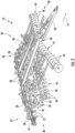
- FIGS. 1 and 2 illustrate differing perspective views of one embodiment of an agricultural implement 10 in accordance with aspects of the present subject matter.
- FIG. 1 illustrates a perspective view of the agricultural implement 10 coupled to a work vehicle 12.
- FIG. 2 illustrates a perspective view of the implement 10, particularly illustrating various components of the implement 10.
- the implement 10 may be configured to be towed across a field in a direction of travel (e.g., as indicated by arrow 14 in FIG. 1 ) by the work vehicle 12.
- the implement 10 may be configured as a tillage implement, and the work vehicle 12 may be configured as an agricultural tractor.
- the implement 10 may be configured as any other suitable type of implement, such as a seed-planting implement, a fertilizer-dispensing implement, and/or the like.
- the work vehicle 12 may be configured as any other suitable type of vehicle, such as an agricultural harvester, a self-propelled sprayer, and/or the like.
- the work vehicle 12 may include a pair of front track assemblies 16, a pair or rear track assemblies 18, and a frame or chassis 20 coupled to and supported by the track assemblies 16, 18.
- An operator's cab 22 may be supported by a portion of the chassis 20 and may house various input devices for permitting an operator to control the operation of one or more components of the work vehicle 12 and/or one or more components of the implement 10.
- the work vehicle 12 may include an engine 24 and a transmission 26 mounted on the chassis 20.
- the transmission 26 may be operably coupled to the engine 24 and may provide variably adjusted gear ratios for transferring engine power to the track assemblies 16, 18 via a drive axle assembly (not shown) (or via axles if multiple drive axles are employed).
- the implement 10 may include a frame 28. More specifically, as shown in FIG. 2 , the frame 28 may extend longitudinally between a forward end 30 and an aft end 32. The frame 28 may also extend laterally between a first side 34 and a second side 36. In this respect, the frame 28 generally includes a plurality of structural frame members 38, such as beams, bars, and/or the like, configured to support or couple to a plurality of components. Furthermore, a hitch assembly 40 may be connected to the frame 28 and configured to couple the implement 10 to the work vehicle 12. Additionally, a plurality of wheels 42 (one is shown) may be coupled to the frame 28 to facilitate towing the implement 10 in the direction of travel 14.
- a hitch assembly 40 may be connected to the frame 28 and configured to couple the implement 10 to the work vehicle 12.
- a plurality of wheels 42 (one is shown) may be coupled to the frame 28 to facilitate towing the implement 10 in the direction of travel 14.
- the frame 28 may be configured to support various ground engaging tools.
- the frame 28 may support one or more gangs or sets 44 of disc blades 46.
- Each disc blade 46 may be configured to penetrate into or otherwise engage the soil as the implement 10 is being pulled through the field.
- the various disc gangs 44 may be oriented at an angle relative to the direction of travel 14 to promote more effective tilling of the soil.
- the implement 10 includes four disc gangs 44 supported on the frame 28 adjacent to its forward end 30.
- the implement 10 may include any other suitable number of disc gangs 44, such as more or fewer than four disc gangs 44.
- the disc gangs 44 may be mounted to the frame 28 at any other suitable location, such as adjacent to its aft end 32.
- the implement frame 28 may be configured to support other ground engaging tools.
- the frame 28 is configured to support a plurality of shanks 50 configured to rip or otherwise till the soil as the implement 10 is towed across the field.
- the frame 28 is also configured to support one or more finishing tools, such as a plurality of leveling blades 52 and/or rolling (or crumbler) basket assemblies 54.
- any other suitable ground-engaging tools may be coupled to and supported by the implement frame 28, such as a plurality of closing discs.
- FIG. 3 a partial, perspective view of the aft end of the implement 10 shown in FIGS. 1 and 2 is illustrated in accordance with aspects of the present subject matter, particularly illustrating a portion of the finishing tools 52, 54 of the implement 10.
- the various finishing tools 52, 54 may be coupled to or supported by the implement frame 28, such as by coupling each tool to a toolbar or laterally extending frame member 38 of the frame 28.
- a blade support arm 60 may be coupled between a given frame member 38 and each leveling blade 52 or set of leveling blades 52 to support the blades 52 relative to the frame 28.
- one or more basket support arms 62 may be coupled between a given frame member 38 and an associated mounting yoke or basket hanger 64 for supporting each basket assembly 54 relative to the frame 28.
- a basket actuator 66 e.g., a hydraulic or pneumatic cylinder
- the basket actuators 66 may also allow the basket assemblies 54 to be raised off the ground, such as when the implement 10 is making a headland turn and/or when the implement 10 is being operated within its transport mode.
- each basket assembly 54 includes a plurality of support plates 70, 72, 74 configured to support a plurality of blades or bars 76 spaced circumferentially about the outer perimeter of the basket.
- each basket assembly 54 includes first and second end plates 70, 72 positioned at the opposed lateral ends of the basket assembly 54 and a plurality of inner support plates 74 spaced apart laterally from one another between the end plates 70, 72.
- Lateral basket sections 78 are generally defined between each pair of adjacent support plates 70, 72, 74, with each basket section 78 being generally characterized by a hollow or substantially hollow interior area surrounded by the lateral portions of the bars 76 extending between the respective pair of adjacent support plates 70, 72, 74.
- the end plates 70, 72 may be rotatably coupled to the corresponding basket hanger 64 (which, in turn, is coupled to the associated bracket support arm(s) 62) via bearings to allow the basket assembly 54 to rotate relative to the hanger/arm 64, 62 as implement 10 is being moved across the field.
- the bars 76 of each basket assembly 54 are configured as formed bars.
- the bars 76 may have any other suitable configuration, such as flat bars, round bars, and/or the like.
- FIG. 3 also illustrates components of one embodiment of a system 100 for monitoring plugging of one or more basket assemblies of an agricultural implement.
- the system 100 is shown as being configured for use in identifying and monitoring a plugged condition(s) of the depicted basket assemblies 54.
- the system 100 may be utilized to monitor plugging of basket assemblies having any other suitable configuration.
- the system 100 includes one or more range sensors 102 installed on the implement 10 at a location relative to each basket assembly 54 such that each range sensor(s) 102 is configured to provide data indicative of a plugged condition of the basket assembly 54.
- each range sensor 102 may be installed relative to an adjacent basket assembly 54 such that the range sensor 102 is configured to transmit detection signals towards the interior of the basket assembly 54 along a line of sight or line of detection 104 ( FIGS.
- the controller 106 may be configured to identify the presence of material accumulation on or within the basket assembly.
- the return signals received by each range sensor 102 may be indicative of the distance defined between the sensor 102 and the corresponding reflection surface.
- the deflection signals transmitted from such range sensor 102 at any given point in time will either be directed towards one of the bars 76 surrounding the interior of the basket assembly 54 or the open space defined between adjacent bars 76, depending on the rotational orientation of the basket assembly 54 relative to the range sensor 102 at such point in time.
- the profile of the distance-related data associated with the return signals received by each range sensor 102 will generally correspond to a periodic or wave-like profile characterized by the deflection signals alternating between being reflected off of the spaced apart bars 76 and being transmitted between adjacent bars 76 through the open interior of the basket assembly 54.
- the detection signals directed from each range sensor 102 towards the open areas defined between adjacent bars 76 will bounce or reflect off the accumulated materials, thereby altering the data trace or profile of the distance-related data associated with the return signals received by the range sensor 102.
- the detection signals directed from each range sensor 102 will bounce or reflect off the accumulated materials as opposed to reflecting off the bars 76 or being transmitted into the interior of the basket assembly 54, thereby altering the data profile of the distance-related data associated with the return signals received by the range sensor 102. Accordingly, by recognizing variations in the data profile (particularly variations indicative of a reduction in the distance detected between the sensor 102 and an associated reflection surface), the controller 106 may infer or estimate that the basket assembly 54 is experiencing a plugged condition. Once a plugged condition is detected, an appropriate control action may then be executed, such as by notifying the operator of the plugged condition or by performing an automated control action.
- the range sensors 102 may correspond to any suitable distance sensors, proximity sensors, and/or the like that are configured to collect data indicative of a distance or range defined between such sensors 102 and a given object/surface.
- each range sensor 102 may correspond to an optical distance sensor, such as a laser-based distance sensor.
- each range sensor 102 may correspond to ultrasound-based distance sensor.
- Laser-based distance sensors and ultrasound-based distance sensors suitable for use within the disclosed system 100 are commercially available from various sources, including, for example, from Banner Engineering Corp. of Minneapolis, MN.
- each range sensor 102 may correspond to any other suitable distance or proximity sensor or sensing device, such as a radar-based distance sensor, an inductance-based distance sensor, a sonar-based distance sensor, magnetic-based distance sensor, a LIDAR sensor, and/or the like.
- the range sensors 102 are mounted to the basket hanger 64 supporting each basket assembly 54 relative to the implement frame 28 (e.g., via the associated basket support arm 62) in a manner such that each range sensor 102 has a downwardly oriented line of sight or line of detection 104 ( FIGS. 4A, 4B, 5A, and 5B ) directed towards the interior of the adjacent basket assembly 54.
- the range sensors 102 are spaced apart laterally across each basket hanger 64 such that at least one range sensor 102 has a downwardly oriented line of detection directed towards the interior of each lateral basket section 78 of the adjacent basket assembly 54.
- the range sensors 102 may allow the plugging state of each respective basket section 78 to be individually monitored.
- the range sensors 102 may be mounted at any other suitable location relative to the basket assembly 54 that allows each range sensor 102 to have a line of detection directed towards the interior of an associated basket assembly 54.
- the illustrated embodiment shows a specific number of range sensors 102 installed relative to each basket assembly 54 (e.g., one per each lateral basket section 78), the system 100 may generally include any suitable number of range sensors 102, including a single range sensor 102 for each basket assembly 54.
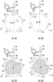
- FIGS. 4A and 4B and FIGS. 5A and 5B schematic, simplified cross-sectional views of one of the basket assemblies 54 shown in FIG. 3 are illustrated in accordance with aspects of the present subject matter.
- FIGS. 4A and 4B illustrate the basket assembly 54 in a non-plugged state such that the basket interior and exterior is completely devoid of material accumulation.
- FIGS. 5A and 5B illustrates the basket assembly 54 when it is experiencing an internal plugged condition such that the basket interior includes field materials (indicated by mass 101) accumulated therein.
- the basket assembly 54 of FIGS. 5A and 5B is shown in an almost fully plugged state.
- basket assemblies 54 can experience varying degrees of plugged conditions, such as ranging from a partially plugged condition to a fully plugged condition.
- the range sensor 102 is coupled to the adjacent basket hanger 64 (e.g., via a mounting bracket 103) such that the sensor 102 has a line of detection 104 oriented towards the interior of the basket assembly 54.
- the line of detection 104 of the sensor 102 is directed towards a center 105 of the basket assembly 54, which may also correspond to the location of the rotational axis of the basket assembly 54.
- the line of detection 104 of the range sensor 102 may be directed towards any other location(s) within the interior of the basket assembly 54, such as any off-center location.
- the line of detection 104 of the range sensors 102 alternates from being aligned with one of the bars 76 of the basket assembly 54 to being aligned with the open area or gap defined adjacent bars 76.
- the line of detection 104 is aligned with one of the bars 76 of the basket assembly 54.
- the detection signals (indicated by arrow 108) transmitted from the range sensor 102 may reflect off the outer surface of the aligned bar 76 and be directed back to the range sensor 102 as return signals (indicated by arrow 109).
- return signals 109 may then be analyzed, for example, to identify the distance between the sensor 102 and the aligned bar 76 (or, as will be described below, to identify distance between the aligned bar 76 and the basket center 105 via a linear transformation).
- the line of detection 104 is aligned with the open space defined between adjacent bars 76 of the basket assembly 54.
- the detection signals 108 transmitted from the range sensor 102 may pass between the adjacent bars 76 and through the open interior of the basket assembly 54 to the basket center 105 or beyond.
- the next adjacent bar 76 will pass through the line of detection 104 of the range sensor 102, thereby allowing the sensor 102 to detect the bar.
- Such alternating pattern will be repeated as the basket assembly 54 rotates relative to the range sensor 102 during operation of the agricultural implement.
- the detection range of the range sensor 102 has generally been selected to generally correspond to the distance defined between the sensor 102 and the basket center 105.
- the range sensor 102 will not receive return signals when the line of detection 104 for the range sensor 102 is aligned with the open space between adjacent bars 76 (e.g., as shown in FIG. 4B ), thereby indicating that the detection signals 108 reached the center 105 of the basket assembly 54.
- the range sensor 102 may have any other suitable detection range.
- the detection range may be selected to correspond to the distance defined between the sensor 102 and the ground (or the opposed side of the basket assembly 54 contacting the ground).
- the detection signals 108 may be transmitted through the interior of the basket assembly 54 and reflect off the opposed side of the basket assembly 54 (e.g., a bar positioned at such opposed side) or the ground and be returned back to the sensor 102 as suitable return signals.
- the same alternating pattern will be repeated as the basket assembly 54 rotates relative to the range sensor 102 during operation of the agricultural implement, with the line of detection 104 alternating between being aligned with one of the bars 76 of the basket assembly 54 and being aligned with the open space defined between adjacent bars 76.
- the line of detection 104 of the range sensor 102 is aligned with one of the bars 76 of the basket assembly 54 in the snapshot shown in FIG. 5A
- the line of detection 104 is aligned with the open space defined between adjacent bars 76 in the snapshot shown in FIG. 5B .
- the detection signals 108 transmitted from the range sensor 102 will not pass through the interior of the basket assembly 54 to its center 105 when the line of detection 104 is aligned with the open space defined between adjacent bars 76 due to the presence of material accumulation within the interior of the basket assembly 54.
- the detection signals 108 transmitted from the range sensor 102 reflect off the outer surface(s) of the accumulated material 101 and are directed back to the range sensor 102 as return signals 109.
- return signals 109 may then be analyzed, for example, to identify the distance between the sensor 102 and the accumulated materials 101 (or, as will be described below, to identify distance between the accumulated materials 101 and the basket center 105 via a linear transformation). When such material accumulation is detected, it may be inferred or determined that the basket assembly 54 is experiencing a plugged condition.
- the basket assembly 54 may also experience an external plugging condition in which field materials accumulate along the outer perimeter of the basket assembly 54, such as on or between the bars 76.
- the range sensor 102 may detect the material accumulation in a manner similar to that described. For instance, material accumulation on the bars 76 will result in a reduction in the distance detected between the sensor and the expected location of the bars 76. Similarly, material accumulation directly between the bars 76 will prevent the detection signals 108 from being transmitted through the interior of the basket assembly 54, which may be detected by the range sensor 102 via the associated return signals 109 reflecting off the accumulated materials.
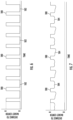
- FIGS. 6 and 7 exemplary charts are provided that illustrate example data traces or profiles associated with the sensor data provided by the range sensor 102 in the non-plugged/plugged scenarios described above with reference to FIGS. 4A and 4B and FIGS. 5A and 5B .
- FIG. 6 illustrates an exemplary data profile associated with the return signals 109 received by the range sensor 102 (or lack thereof) while the basket assembly 54 is in the non-plugged state shown in FIGS. 4A and 4B .
- FIG. 7 illustrates an exemplary data profile associated with the return signals 109 received by the range sensor 102 while the basket assembly 54 is in the plugged state shown in FIGS. 5A and 5B .
- the data collected from the range sensor 102 is generally indicative of the distance defined between the sensor 102 and the detected surface(s).
- the sensor data has been plotted as a function of the distance of the detected surface from the center 105 of the basket assembly 54.
- Such center-referenced data may be obtained via a linear transformation. In doing so, any sensor measurements that extend beyond the center 105 of the basket assembly 54 (e.g., when the detection range of the range sensor 102 extends past the basket center 105) may be saturated prior to performing the linear transformation.
- the sensor data may exhibit a periodic or alternating profile as the line of detection 104 of the range sensor 102 alternates between being aligned with one of the bars 76 and being aligned with the open spaces defined between adjacent bars 76.
- the data trace is characterized by a repeating pattern of peaks 180 and valleys 182, with each peak 180 corresponding to the time period across which one of the bars 76 of the basket assembly 54 is being rotated across the line of detection 104 of the sensor 102 and each valley 182 corresponding to the time period across which the detection signals 108 from the range sensor 102 are being transmitted between adjacent bars 76 through the interior of the basket assembly 54 to at least the basket center 105.
- each peak 180 corresponds to a distance from the basket center 108 equal to an outer radius R (see FIG. 4A ) of the basket assembly 54 (i.e., the distance from the basket center 105 to the outer surfaces of the bars 76), while each valley 182 corresponds to a distance from the basket center 105 equal to zero.
- the non-plugged data trace or profile for the basket assembly 54 generally exhibits a periodic profile with a very high variation or differential in the detected distances between the peaks 180 and valleys 182.
- the data trace or profile associated with the sensor data received from the range sensor 102 differs significantly when the basket assembly 54 is experiencing a plugged condition. Specifically, due to the detection of material accumulation, the variability in the detected distances is reduced significantly.
- the data trace is characterized a similar repeating pattern of peaks 180 and valleys 184 as that described above with reference to FIG. 6 , with each peak 180 corresponding to the time period across which one of the bars 76 of the basket assembly 54 is being rotated across the line of detection 104 of the sensor 102.
- the data trace is characterized a similar repeating pattern of peaks 180 and valleys 184 as that described above with reference to FIG. 6 , with each peak 180 corresponding to the time period across which one of the bars 76 of the basket assembly 54 is being rotated across the line of detection 104 of the sensor 102.
- each valley 184 corresponds to the time period across which the detection signals from the range sensor 102 are being transmitted between adjacent bars 76 and being reflected off the accumulated field materials.
- the variation between the detected distance from the basket center 105 to the outer surfaces of the bars 76 and the detected distances from the basket center 105 to the outer surface(s) of the accumulated materials is significantly smaller than the distance variations described above with reference to FIG. 6 .
- Such a reduced differential between the maximum and minimum distance values detected during rotation of the basket assembly 54 provides a significant indicator of material accumulation relative to the basket assembly.
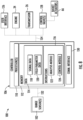
- FIG. 8 a schematic view of one embodiment of a system 100 for monitoring plugging of one or more basket assemblies of an agricultural implement is illustrated in accordance with aspects of the present subject matter.
- the system 100 will be described with reference to the implement 10 shown in FIGS. 1 and 2 and the basket assembly 54 and associated system components shown in FIG. 3 .
- the disclosed system 100 may be utilized to identifying tool plugging in association with any other suitable agricultural implement having any other suitable implement configuration, any other suitable basket assembly having any other suitable basket configuration, and/or using system components having any other suitable component configuration(s).
- the system 100 may include one or more range sensors 102 installed relative to a basket assembly 54 such that each range sensor(s) 102 is configured to provide data indicative of a plugged condition of the basket assembly 54. Additionally, as indicated above, the system 100 may also include a controller 106 communicatively coupled to the range sensor(s) 102. As will be described in greater detail below, the controller 106 may be configured to analyze the return signals received by the range sensor(s) 102 (or the lack thereof) and/or related data associated with such signals to infer or estimate the existence of material accumulation on and/or within the associated basket assembly 54.
- the controller 106 may also be configured to execute one or more control actions in response to the determination that the basket assembly 54 is likely plugged or in the process of becoming plugged. For instance, in one embodiment, the controller 106 may notify the operator that the basket assembly 54 is plugged or is likely to become plugged in the near future. In addition to notifying the operator (or as an alternative thereto), the controller 106 may be configured to execute one or more automated control actions adapted to de-plug the basket assembly 54 or otherwise reduce the amount of material accumulation on and/or within the basket assembly 54, such as by automatically adjusting the speed of the implement 10 and/or the down force applied to the basket assembly 54 and/or by automatically raising and lowering the basket assembly 54 relative to the ground.
- the controller 106 may correspond to any suitable processor-based device(s), such as a computing device or any combination of computing devices.
- the controller 106 may generally include one or more processor(s) 110 and associated memory devices 112 configured to perform a variety of computer-implemented functions (e.g., performing the methods, steps, algorithms, calculations and the like disclosed herein).
- processor refers not only to integrated circuits referred to in the art as being included in a computer, but also refers to a controller, a microcontroller, a microcomputer, a programmable logic controller (PLC), an application specific integrated circuit, and other programmable circuits.
- PLC programmable logic controller
- the memory 112 may generally comprise memory element(s) including, but not limited to, computer readable medium (e.g., random access memory (RAM)), computer readable nonvolatile medium (e.g., a flash memory), a floppy disk, a compact disc-read only memory (CD-ROM), a magneto-optical disk (MOD), a digital versatile disc (DVD) and/or other suitable memory elements.
- RAM random access memory
- RAM computer readable nonvolatile medium
- CD-ROM compact disc-read only memory
- MOD magneto-optical disk
- DVD digital versatile disc
- Such memory 112 may generally be configured to store information accessible to the processor(s) 110, including data 114 that can be retrieved, manipulated, created and/or stored by the processor(s) 110 and instructions 116 that can be executed by the processor(s) 110.
- the data 114 may be stored in one or more databases.
- the memory 112 may include a signal database 118 for storing the return signals received by the range sensor(s) 102 and/or data associated with the received signals.
- data may be stored within the signal database 118 associated with the distance defined between the sensor(s) 102 and the detected surface.
- the signal database 118 may also be used to store any modified or transformed sensor data, such as when it is desired to transform the distance data from being referenced relative to the sensor location to being referenced relative to the center 105 of the basket assembly 54 or any other suitable reference location.
- the memory 112 may include a field parameter database 120 for storing information related to one or more parameters of the field being processed during the performance of the associated agricultural operation (e.g., a tillage operation).
- moisture data associated with the moisture content or level of the soil within the field may be stored within the field parameter database 120.
- the wetness or moisture content of the soil may impact the ability of the range sensor(s) 102 of detecting plugged conditions. For instance, material accumulation including significantly high soil moisture may alter the manner in which the detection signals reflect off the accumulated field materials, which may negatively impact the resulting return signals received by the range sensor(s) 102. Accordingly, by knowing the soil moisture within the field, the controller 106 may be configured to more accurately assess the return signals received by the range sensor(s) 102.
- the moisture data may be correspond to pre-existing or predetermined moisture data stored within the field parameter database 120 or the moisture data may correspond to sensor data that is being actively collected or generated during the performance of the associated agricultural operation.
- the controller 106 may be provided with soil moisture data (e.g., in the form of a soil moisture map) that was collected during a previous agricultural operation or that was generated based on previously known data associated with the field conditions.
- a soil moisture sensor may be provided in operative association with the implement 10 or the towing vehicle 12 to allow the soil moisture to be actively monitored during the performance of the associated agricultural operation.
- the instructions 116 stored within the memory 112 of the controller 106 may be executed by the processor(s) 110 to implement an analysis module 122.
- the analysis module 122 may be configured to analyze the return signals received by each range sensor(s) 102 (or a lack thereof) and/or the related data (e.g., distance data) to estimate or infer when the associated basket assembly 54 is experiencing a plugged condition.
- the analysis module 122 may be configured to determine when the basket assembly 54 is experiencing a plugged condition by analyzing the data trace or profile of the data associated with the return signals received by each range sensor(s) 102.
- the analysis module 122 may be configured to compare or analyze the current data trace or profile associated with the sensor data in view of a predetermined, non-plugged data trace or profile, such as the non-plugged data profile described above with reference to FIG. 6 .
- the analysis module 122 may, for example, compare the variability or differential in the distance data detected within the current data profile to the variability or differential of the distance data associated with the non-plugged data profile. If a significant variation exists between the current data profile and the non-plugged data profile (e.g., a variation indicating that the distance variability or differential in the current data profile is significantly reduced relative to the distance variability or differential in the non-plugged data profile), the analysis module 122 may estimate or infer that the associated basket assembly is experiencing a plugged condition.
- the analysis module 122 may be configured to analyze the distance data associated with the return signals received by each range sensor(s) 102 (or a lack thereof) by calculating a detection range metric for the associated range sensor 102.
- the detection range metric may be indicative of a percentage of the detection signals transmitted from a given range sensor 102 that reach a given location within the interior of the basket assembly 54 (or that reach to within a given range of locations defined relative to such location within the interior of the basket assembly 54).
- the analysis module 122 may then be configured to determine when the basket assembly 54 is experiencing a plugged condition based at least in part on the detection range metric. For instance, the analysis module 122 may be configured to compare the calculated detection range metric to a predetermined threshold. In such an embodiment, it may be inferred or estimated that the basket assembly 54 is experiencing a plugged condition when the detection range metric crosses such predetermined threshold (e.g., by falling below the threshold).
- the detection range metric may be indicative of a percentage of the detection signals transmitted from a given range sensor 102 that reach the center 105 of the basket assembly 54 (or at least within a given radius of the center 105 of the basket assembly 54).
- the analysis module 122 may be configured to calculate a proximity center crossing (PCC) metric indicative of the percentage of detection signals that reach within a given radius defined from the basket center 105 (e.g., a radius of less than 10 centimeters (cm), such as a radius of less than 7.5 cm or less than 5 cm or less than 2.5 cm) across a given time period (e.g., a time period of 1 second, 2 seconds, 3 seconds, and/or the like).
- PCC proximity center crossing
- a higher PCC percentage value indicates that a significant amount of the detection signals transmitted by the range sensor 102 are able to reach down to a location at or adjacent to the basket center 105, thereby indicating that the basket assembly 54 is likely in an non-plugged state.
- a lower PCC percentage value indicates that a smaller amount of the detection signals transmitted by the range sensor 102 were able to reach down to a location at or adjacent to the basket center, thereby indicating that the basket assembly 54 is likely experiencing a plugged condition.
- to assess the current PCC percentage value calculated for a given range sensor 102 such value may be compared to a predetermined PCC threshold.
- the PCC threshold may be set to a given percentage value, such as a percentage ranging from about 70% to about 10%, or from about 60% to about 20%, or from about 50% to about 30%, or from about 45% to about 35%, and/or any other subranges therebetween.
- a given percentage value such as a percentage ranging from about 70% to about 10%, or from about 60% to about 20%, or from about 50% to about 30%, or from about 45% to about 35%, and/or any other subranges therebetween.
- the current PCC percentage value calculated for a given range sensor 203 crosses or drops below the predetermined PPC threshold, it may be inferred or estimated that the basket assembly 54 is experiencing a plugged condition at the location along the basket assembly 54 at which the range sensor 102 is directed.
- the PCC threshold is set as 40%, any PCC percentage value below such threshold indicates that less than 40% of the detection signals transmitted from the associated range sensor 102 are currently reaching a location within the predetermined radius defined from the basket center 105.
- the system 100 may include a plurality of range sensors 102, with at least one range sensor 102 being aligned with each lateral basket section 78 of a given basket assembly 54 to allow material accumulation to be detected on a section-level basis for the basket assembly 54.
- the analysis module 122 may be configured to individually analyze the return signals and/or associated signal data received by each range sensor 102 to determine whether a plugged condition exists within the localized area being detected by each range sensor 102.
- the instructions 116 stored within the memory 112 of the controller 106 may also be executed by the processor(s) 110 to implement a control module 124.
- the control module 124 may be configured to initiate a control action when it is determined that a basket assembly of an agricultural implement is experiencing a plugged condition.
- the control module 124 may be configured to provide a notification to the operator of the vehicle/implement 12/10 indicating that material accumulation is present on or within one or more of the basket assemblies 54 of the implement 10.
- the control module 124 may cause a visual or audible notification or indicator to be presented to the operator via an associated user interface 126 provided within the cab 22 of the vehicle 10.
- control module 124 may be configured to execute an automated control action designed to adjust the operation of the implement 10.
- the controller 106 may be configured to increase or decrease the operational or ground speed of the implement 10 in an attempt to reduce the amount of material accumulation and/or to limit further material accumulation.
- the controller 106 may be communicatively coupled to both the engine 24 and the transmission 26 of the work vehicle 12.
- the controller 106 may be configured to adjust the operation of the engine 24 and/or the transmission 26 in a manner that increases or decreases the ground speed of the work vehicle 12 and, thus, the ground speed of the implement 10, such as by transmitting suitable control signals for controlling an engine or speed governor (not shown) associated with the engine 24 and/or transmitting suitable control signals for controlling the engagement/disengagement of one or more clutches (not shown) provided in operative association with the transmission 26. It should be appreciated that controller 106 may also be configured to decrease the ground speed in a manner that brings vehicle/implement 12/10 to a complete stop.
- the controller 106 may also be configured to adjust an operating parameter associated with the ground-engaging tools of the implement 10.
- the controller 106 may be communicatively coupled to one or more valves 128 configured to regulate the supply of fluid (e.g., hydraulic fluid or air) to one or more corresponding actuators of the implement 10, such as the basket actuators 66.
- the controller 106 may automatically adjust the down force or down pressure applied to the associated basket assembly 54.
- the controller 106 may control the operation of the basket actuator 66 to raise and lower the associated basket assembly 54 relative to the ground.
- the controller 106 may also include a communications interface 130 to provide a means for the controller 106 to communicate with any of the various other system components described herein.
- a communications interface 130 to provide a means for the controller 106 to communicate with any of the various other system components described herein.
- one or more communicative links or interfaces 132 e.g., one or more data buses
- one or more communicative links or interfaces 134 may be provided between the communications interface 134 and the engine 24, the transmission 26, the user interface 126, the control valves 128, and/or the like to allow the controller 106 to control the operation of and/or otherwise communicate with such system components.
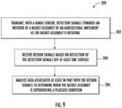
- FIG. 9 a flow diagram of one embodiment of a method 200 for monitoring plugging of basket assemblies of an agricultural implement is illustrated in accordance with aspects of the present subject matter.
- the method 200 will be described herein with reference to the agricultural implement 10, the basket assembly 54, and the system 100 described above with reference to FIGS. 1-3 and 8 .
- the disclosed method 200 may generally be implemented with any agricultural implement having any suitable implement configuration, any basket assembly having any suitable basket configuration, and/or any system having any suitable system configuration.
- FIG. 9 depicts steps performed in a particular order for purposes of illustration and discussion, the methods discussed herein are not limited to any particular order or arrangement.
- steps of the methods disclosed herein can be omitted, rearranged, combined, and/or adapted in various ways without deviating from the scope of the present disclosure.
- the method 200 may include transmitting, with a range sensor, detection signals towards an interior of a basket assembly of an agricultural implement as the basket assembly is rotating.
- a range sensor For example, as indicated above, one or more range sensors 102 may be installed relative to a basket assembly 54 of an agricultural implement 10, with each range sensor 102 being configured to transmit detection signals along a line of detection 104 towards the interior of the basket assembly 54.
- the method 200 may include receiving return signals based on reflection of the detection signals off at least one surface.
- the detection signals transmitted from each range sensor 102 may reflect off a given surface (e.g., the outer surface of the bars 76 of the associated basket assembly 54 and/or the surface(s) of the accumulated field materials) and be subsequently detected as return signals by the range sensor.
- the method 200 may include analyzing data associated at least in part with the return signals to determine when the basket assembly is experiencing a plugged condition.
- the controller 106 may be configured to infer or estimate that a basket assembly 54 is experiencing a plugged condition by identifying variations in a data profile or trace associated with the data received from each range sensor and/or by comparing a calculated metric (e.g., a detection range metric, such as the PCC metric described above) to a predetermined threshold.
- a calculated metric e.g., a detection range metric, such as the PCC metric described above
- the steps of the method 200 are performed by the controller 106 upon loading and executing software code or instructions which are tangibly stored on a tangible computer readable medium, such as on a magnetic medium, e.g., a computer hard drive, an optical medium, e.g., an optical disc, solid-state memory, e.g., flash memory, or other storage media known in the art.
- a tangible computer readable medium such as on a magnetic medium, e.g., a computer hard drive, an optical medium, e.g., an optical disc, solid-state memory, e.g., flash memory, or other storage media known in the art.
- any of the functionality performed by the controller 106 described herein, such as the method 200 is implemented in software code or instructions which are tangibly stored on a tangible computer readable medium.
- the controller 106 loads the software code or instructions via a direct interface with the computer readable medium or via a wired and/or wireless network. Upon loading and executing such software code or instructions by the controller 106
Landscapes
- Life Sciences & Earth Sciences (AREA)
- Engineering & Computer Science (AREA)
- Mechanical Engineering (AREA)
- Soil Sciences (AREA)
- Environmental Sciences (AREA)
- Management, Administration, Business Operations System, And Electronic Commerce (AREA)
- Geophysics And Detection Of Objects (AREA)
Claims (15)
- System (100) zur Überwachung des Verstopfens von Korbanordnungen für landwirtschaftliche Arbeitsgeräte (10), wobei das System umfasst:eine Korbanordnung (54), die dazu eingerichtet ist, von einem landwirtschaftlichen Arbeitsgerät (10) getragen zu werden;einen Wegsensor (102), der bezüglich der Korbanordnung (54) derart angeordnet ist, dass der Wegsensor (102) dazu eingerichtet ist, Detektionssignale in das Innere der Korbanordnung (54) auszusenden und Rücksignale basierend auf der Reflexion der Detektionssignale an einer Reflexionsfläche zu erhalten; undeine Steuerung (106), die mit dem Wegsensor (102) in Kommunikationsverbindung steht,wobei das System (100) dadurch gekennzeichnet ist, dassdie Steuerung (106) dazu eingerichtet ist, Veränderungen in einem Datenprofil der abstandsbezogenen Daten, die den Rücksignalen zugeordnet sind, die von dem Wegsensor (102) empfangen werden, wenn sich die Korbanordnung (54) bezüglich des Wegsensors (102) dreht, zu analysieren, um zu bestimmen, dass die Korbanordnung (54) verstopft ist, wenn die Veränderungen in dem Datenprofil eine Verringerung eines Abstands andeuten, der zwischen dem Wegsensor (102) und der Reflexionsfläche detektiert wird.
- System (100) nach Anspruch 1, wobei die Steuerung (106) dazu eingerichtet ist, eine Detektionsabstandskennzahl zu berechnen, die charakteristisch für einen Anteil der Detektionssignale ist, die zumindest eine aus einer vorbestimmten Stelle in dem Inneren der Korbanordnung (54) und einem Bereich von Stellen, der bezüglich der vorbestimmten Stelle in dem Inneren der Korbanordnung (54) definiert ist, erreichen, wobei die Steuerung (106) dazu eingerichtet ist, zumindest teilweise basierend auf der Detektionsabstandskennzahl zu bestimmen, wenn die Korbanordnung (54) verstopft ist.
- System (100) nach Anspruch 2, wobei die Steuerung (106) dazu eingerichtet ist, die berechnete Detektionsabstandskennzahl mit einem vorbestimmten Grenzwert zu vergleichen, wobei die Steuerung (106) dazu eingerichtet ist, zu bestimmen, dass die Korbanordnung (54) verstopft ist, wenn die Detektionsabstandskennzahl den vorbestimmten Grenzwert überschreitet.
- System (100) nach Anspruch 2, wobei die vorbestimmte Stelle einen Mittelpunkt der Korbanordnung (54) umfasst.
- System (100) nach Anspruch 1, wobei die Steuerung (106) dazu eingerichtet ist, zu bestimmen, dass die Korbanordnung (54) verstopft ist, indem Veränderungen in einem Profil der Daten, die von dem Wegsensor (102) erhalten werden, identifiziert werden, wenn die Korbanordnung (54) gedreht wird.
- System (100) nach Anspruch 5, wobei die Korbanordnung (54) eine Mehrzahl von beabstandeten Stäben (76) umfasst, die das Innere des Korbes umgeben, wobei sich jeder der Mehrzahl von beabstandeten Stäben (76) durch eine Detektionslinie erstreckt, entlang derer die Detektionssignale in das Innere der Korbanordnung (54) ausgesendet werden, wenn die Korbanordnung (54) gedreht wird.
- System (100) nach Anspruch 6, wobei die Steuerung (106) dazu eingerichtet ist, das Profil der Daten mit einem nicht-verstopften Datenprofil zu vergleichen, wobei das nicht-verstopfte Datenprofil ein periodisches Profil umfasst, das durch die Auslenkungssignale gekennzeichnet ist, die zwischen Reflexion an der Mehrzahl von beabstandeten Stäben (76) und Übertragen zwischen benachbarten Stäben (76) der Mehrzahl von beabstandeten Stäben (76) in das Innere der Korbanordnung (54) wechseln.
- System (100) nach Anspruch 1, wobei die Korbanordnung (54) eine Mehrzahl von seitlichen Korbabschnitten (78) umfasst, wobei jeder seitliche Korbabschnitt (78) zwischen benachbarten Halteplatten (70, 72, 74) der Korbanordnung (54) definiert ist, und wobei der Wegsensor (102) einen aus einer Mehrzahl von Wegsensoren (102) umfasst, die relativ zu der Korbanordnung (54) angebracht sind, wobei die Mehrzahl von Wegsensoren (102) bezüglich der Korbanordnung (54) derart angeordnet ist, dass zumindest ein Wegsensor (102) der Mehrzahl von Wegsensoren (102) dazu eingerichtet ist, Detektionssignale in Richtung eines Abschnitts des Inneren der Korbanordnung (54) zu übertragen, der durch einen jeweiligen seitlichen Korbabschnitt (78) der Mehrzahl von seitlichen Korbabschnitten (78) definiert ist.
- System (100) nach Anspruch 8, wobei die Steuerung (106) weiterhin dazu eingerichtet ist, zu bestimmen, wenn ein bestimmter seitlicher Korbabschnitt (78) der Mehrzahl von seitlichen Korbabschnitten (78) verstopft ist, indem die Daten analysiert werden, die von dem mindestens einen Wegsensor (102) erhalten werden, der Detektionssignale in Richtung des Abschnitts des Inneren der Korbanordnung (54) aussendet, der durch einen solchen seitlichen Korbabschnitt (78) definiert ist.
- System (100) nach Anspruch 1, wobei die Wegsensoren (102) mindestens einen aus einem optischen Wegsensor und einem ultraschallbasierten Wegsensor umfasst.
- Landwirtschaftliches Arbeitsgerät (10) mit:einem Rahmen (28);einem System (100) zur Überwachung des Verstopfens nach einem der vorhergehenden Ansprüche, wobei die Korbanordnung (54) des Systems (100) von dem Rahmen (28) getragen wird.
- Verfahren zur Überwachung des Verstopfens von Korbanordnungen (54) von landwirtschaftlichen Arbeitsgeräten (10), wobei das Verfahren umfasst:Aussenden, mit einen Wegsensor (102), von Detektionssignalen in das Innere einer Korbanordnung (54) eines landwirtschaftlichen Arbeitsgeräts (10), wenn sich die Korbanordnung (54) dreht;Erhalten von Rücksignalen basierend auf der Reflexion der Detektionssignale an einer Reflexionsfläche; undAnalysieren, mit einer Computereinrichtung (106), von Veränderung in einem Datenprofil von abstandbezogenen Daten, die den Rücksignalen zugeordnet sind, die von dem Wegsensor (102) erhalten werden, wenn sich die Korbanordnung (54) bezüglich des Wegsensors (102) dreht, um zu bestimmen, dass die Korbanordnung (54) verstopft ist, wenn die Veränderungen in dem Datenprofil eine Verringerung eines Abstands anzeigen, der zwischen dem Wegsensor (102) und der Reflexionsfläche detektiert wird.
- Verfahren nach Anspruch 12, weiterhin umfassend das Steuern eines Betriebs des landwirtschaftlichen Arbeitsgeräts (10), um einen Betriebsparameter einzustellen, der dem landwirtschaftlichen Arbeitsgerät (10) zugeordnet ist, wenn identifiziert wird, dass die Korbanordnung (54) verstopft ist.
- Verfahren nach Anspruch 12, weiterhin umfassend das Bestimmen einer Detektionsabstandskennzahl, die charakteristisch für einen Anteil der Detektionssignale ist, die zumindest eines aus einer vorbestimmten Stelle in dem Inneren der Korbanordnung (54) und einem Bereich von Stellen erreichen, die bezüglich der vorbestimmten Stelle in dem Inneren der Korbanordnung (54) definiert sind.
- Verfahren nach Anspruch 12, wobei das Analysieren der Daten, die von dem Wegsensor erhalten werden, das Identifizieren von Veränderung in einem Profil der Daten umfasst, die von dem Wegsensor erhalten werden, um zu bestimmen, wenn die Korbanordnung verstopft ist.
Applications Claiming Priority (2)
| Application Number | Priority Date | Filing Date | Title |
|---|---|---|---|
| US16/541,319 US11369052B2 (en) | 2019-08-15 | 2019-08-15 | System and method for monitoring plugging of basket assemblies of an agricultural implement |
| PCT/US2020/046051 WO2021030519A1 (en) | 2019-08-15 | 2020-08-13 | System and method for monitoring plugging of basket assemblies of an agricultural implement |
Publications (2)
| Publication Number | Publication Date |
|---|---|
| EP4013208A1 EP4013208A1 (de) | 2022-06-22 |
| EP4013208B1 true EP4013208B1 (de) | 2025-04-02 |
Family
ID=72266827
Family Applications (1)
| Application Number | Title | Priority Date | Filing Date |
|---|---|---|---|
| EP20764201.8A Active EP4013208B1 (de) | 2019-08-15 | 2020-08-13 | System und verfahren zur verstopfüberwachung von korbanordnungen eines landwirtschaftlichen anbaugeräts |
Country Status (4)
| Country | Link |
|---|---|
| US (1) | US11369052B2 (de) |
| EP (1) | EP4013208B1 (de) |
| CA (1) | CA3146571A1 (de) |
| WO (1) | WO2021030519A1 (de) |
Families Citing this family (8)
| Publication number | Priority date | Publication date | Assignee | Title |
|---|---|---|---|---|
| DK3476188T3 (da) * | 2017-10-30 | 2022-08-08 | Kverneland Group Les Landes Genusson | Fremgangsmåde og system til bestemmelse og lagring af overfladeforhold for en mark |
| US11191202B2 (en) * | 2019-08-13 | 2021-12-07 | Cnh Industrial Canada, Ltd. | System and method for de-plugging rotating ground engaging tools of an agricultural implement |
| US20210105942A1 (en) * | 2019-10-15 | 2021-04-15 | Cnh Industrial America Llc | System and method for monitoring plugging of basket assemblies of an agricultural implement |
| US12302771B2 (en) * | 2021-03-29 | 2025-05-20 | Cnh Industrial America | Systems and methods for detecting material accumulation relative to disk gang assemblies of agricultural implements |
| US12207578B2 (en) | 2022-08-17 | 2025-01-28 | Cnh Industrial America Llc | Finishing tool assembly position control system for an agricultural tillage implement |
| US20240196771A1 (en) * | 2022-12-19 | 2024-06-20 | Cnh Industrial Canada, Ltd. | System and method for monitoring plugging of basket assemblies of an agricultural implement |
| US20240268250A1 (en) * | 2023-02-10 | 2024-08-15 | Cnh Industrial America Llc | System and method for monitoring plugging of basket assemblies of an agricultural implement |
| US12419209B2 (en) | 2023-07-13 | 2025-09-23 | Cnh Industrial America Llc | System and method for reducing shank wear on an agricultural implement |
Family Cites Families (32)
| Publication number | Priority date | Publication date | Assignee | Title |
|---|---|---|---|---|
| US3863428A (en) | 1973-11-14 | 1975-02-04 | Robert L Baxter | Blockage monitor for a cotton picking machine |
| US4286424A (en) | 1980-04-11 | 1981-09-01 | Deere & Company | Blockage detector for a cotton harvester |
| US5063729A (en) | 1990-09-19 | 1991-11-12 | Deere & Company | Cotton harvester blockage detection method and flow sensor therefor |
| US5425223A (en) | 1994-05-23 | 1995-06-20 | Delaronde; Troy J. P. | Grass mower blockage monitor |
| DE19726917A1 (de) | 1997-06-25 | 1999-01-07 | Claas Selbstfahr Erntemasch | Vorrichtung an Landmaschinen zur berührungslosen Abtastung von sich über den Boden erstreckenden Konturen |
| DE19853085B4 (de) | 1998-11-18 | 2014-03-20 | Claas Selbstfahrende Erntemaschinen Gmbh | Verfahren zum Justieren einer an einer Feldmaschine befestigten Sensoreinheit sowie eine Justiereinrichtung und eine Feldmaschine |
| US6438506B1 (en) | 1999-09-29 | 2002-08-20 | Case Corporation | Apparatus and method for determining ground speed of a work vehicle |
| US6956348B2 (en) | 2004-01-28 | 2005-10-18 | Irobot Corporation | Debris sensor for cleaning apparatus |
| US6990390B2 (en) | 2004-05-19 | 2006-01-24 | Caterpillar Inc. | Method and apparatus to detect change in work tool |
| US7143836B2 (en) | 2004-10-14 | 2006-12-05 | Cnh America Llc | Soil conditioning rotary reel for primary tillage operations |
| US7354341B1 (en) | 2007-03-29 | 2008-04-08 | Cnh America Llc | System and method for detecting an air flow condition indicative of plugging of a discharge apparatus of an agricultural combine |
| US8326500B2 (en) | 2009-11-17 | 2012-12-04 | Deere & Company | Row unit wheel turning monitor for an agricultural machine |
| US9232687B2 (en) | 2010-09-15 | 2016-01-12 | Dawn Equipment Company | Agricultural systems |
| US8408149B2 (en) | 2011-05-20 | 2013-04-02 | Deere & Company | Ground working machine with a blockage clearing system and method of operation |
| US10151839B2 (en) | 2012-06-01 | 2018-12-11 | Agerpoint, Inc. | Systems and methods for determining crop yields with high resolution geo-referenced sensors |
| US8928486B2 (en) | 2012-08-14 | 2015-01-06 | Cnh Industrial Canada, Ltd. | Pressure-based blockage detection system and method in crop production systems |
| US9326439B2 (en) | 2013-01-31 | 2016-05-03 | Summers Manufacturing Company, Inc. | Agricultural implement with a scraper internal to a rolling basket |
| US9405039B2 (en) | 2014-04-22 | 2016-08-02 | Deere & Company | Ground engaging member accumulation determination |
| US9485900B2 (en) | 2014-09-29 | 2016-11-08 | Deere & Company | Agricultural implement plug detection |
| WO2017049186A1 (en) | 2015-09-18 | 2017-03-23 | Precision Planting Llc | Apparatus, system and method for monitoring soil criteria during tillage operations and control of tillage tools |
| US10194573B2 (en) | 2015-09-23 | 2019-02-05 | Deere & Company | Anti-tangle harrow attachment |
| US10412878B2 (en) | 2016-11-23 | 2019-09-17 | Cnh Industrial Canada, Ltd. | Down pressure compensation for tillage baskets traveling at varying speeds |
| US10255670B1 (en) | 2017-01-08 | 2019-04-09 | Dolly Y. Wu PLLC | Image sensor and module for agricultural crop improvement |
| US10429511B2 (en) | 2017-05-04 | 2019-10-01 | The Boeing Company | Light detection and ranging (LIDAR) ice detection system |
| SI25432A (sl) | 2017-05-08 | 2018-11-30 | Branko Kos | Naprava in postopek za nadzorovanje vibracij na kmetijskem stroju, kot je mulčer |
| US10816426B2 (en) | 2017-06-16 | 2020-10-27 | Cnh Industrial America Llc | Pressure sensor for detecting a pressure differential |
| US11058045B2 (en) * | 2018-10-29 | 2021-07-13 | Cnh Industrial America Llc | System and method for detecting accumulations of field materials between ground engaging components of an agricultural implement |
| US11202402B2 (en) * | 2019-07-24 | 2021-12-21 | Cnh Industrial America Llc | System and method for identifying plugging of ground engaging tools based on wireless signal detection |
| US20210029865A1 (en) * | 2019-07-29 | 2021-02-04 | Cnh Industrial America Llc | System for determining material accumulation relative to ground engaging tools of an agricultural implement and related methods |
| US11191202B2 (en) * | 2019-08-13 | 2021-12-07 | Cnh Industrial Canada, Ltd. | System and method for de-plugging rotating ground engaging tools of an agricultural implement |
| US20210105942A1 (en) * | 2019-10-15 | 2021-04-15 | Cnh Industrial America Llc | System and method for monitoring plugging of basket assemblies of an agricultural implement |
| US11234355B2 (en) * | 2019-10-30 | 2022-02-01 | Cnh Industrial America Llc | System and method for managing material accumulation relative to ground engaging tools of an agricultural implement |
-
2019
- 2019-08-15 US US16/541,319 patent/US11369052B2/en active Active
-
2020
- 2020-08-13 CA CA3146571A patent/CA3146571A1/en active Pending
- 2020-08-13 WO PCT/US2020/046051 patent/WO2021030519A1/en not_active Ceased
- 2020-08-13 EP EP20764201.8A patent/EP4013208B1/de active Active
Also Published As
| Publication number | Publication date |
|---|---|
| EP4013208A1 (de) | 2022-06-22 |
| WO2021030519A1 (en) | 2021-02-18 |
| US20210045274A1 (en) | 2021-02-18 |
| CA3146571A1 (en) | 2021-02-18 |
| US11369052B2 (en) | 2022-06-28 |
Similar Documents
| Publication | Publication Date | Title |
|---|---|---|
| EP4013208B1 (de) | System und verfahren zur verstopfüberwachung von korbanordnungen eines landwirtschaftlichen anbaugeräts | |
| EP3808162B1 (de) | System und verfahren zur überwachung des verstopfens von walzenanordnungen eines landwirtschaftlichen anbaugeräts | |
| EP4002979B1 (de) | System zur bestimmung von materialansammlungen bei bodenbearbeitungswerkzeugen eines landwirtschaftlichen geräts und zugehörige verfahren | |
| EP3815480B1 (de) | System und verfahren zur detektion von werkzeugverstopfung eines landwirtschaftlichen anbaugeräts auf basis von rückstandsunterschieden | |
| EP3403478B1 (de) | System und verfahren zur überwachung von bodenverhältnissen innerhalb eines feldes | |
| EP3815482B1 (de) | Vorrichtung und verfahren zur detektion der ebenheit von werkzeugen eines bodenbearbeitungsgeräts auf basis der werkzeugbelastung | |
| EP3400764A1 (de) | System und verfahren zur erkennung eines bodeneingriffswerkzeugschwimmers für ein landwirtschaftliches arbeitsgerät | |
| CA3146273A1 (en) | System and method for detecting a plug of a tool of a tillage implement | |
| US11234355B2 (en) | System and method for managing material accumulation relative to ground engaging tools of an agricultural implement | |
| EP3815481B1 (de) | System und verfahren zur erkennung von verstopfungen von bodeneingriffswerkzeugen auf der basis drahtloser signalerfassung | |
| EP4021160B1 (de) | System und verfahren zur detektion der ebenheit von werkzeugen eines bodenbearbeitungsgeräts auf basis eines materialflusses | |
| US11202402B2 (en) | System and method for identifying plugging of ground engaging tools based on wireless signal detection | |
| US11445654B2 (en) | System and method for identifying plugging of ground engaging tools based on lifting pressure | |
| US20250138180A1 (en) | System and method for monitoring plugging of basket assemblies of an agricultural implement | |
| US20240196771A1 (en) | System and method for monitoring plugging of basket assemblies of an agricultural implement | |
| US20240183835A1 (en) | Systems and methods for monitoring disc conditions of agricultural implements | |
| US20230380326A1 (en) | Systems and methods for monitoring disc conditions of agricultural implements using distance-based measurements |
Legal Events
| Date | Code | Title | Description |
|---|---|---|---|
| STAA | Information on the status of an ep patent application or granted ep patent |
Free format text: STATUS: UNKNOWN |
|
| STAA | Information on the status of an ep patent application or granted ep patent |
Free format text: STATUS: THE INTERNATIONAL PUBLICATION HAS BEEN MADE |
|
| PUAI | Public reference made under article 153(3) epc to a published international application that has entered the european phase |
Free format text: ORIGINAL CODE: 0009012 |
|
| STAA | Information on the status of an ep patent application or granted ep patent |
Free format text: STATUS: REQUEST FOR EXAMINATION WAS MADE |
|
| 17P | Request for examination filed |
Effective date: 20220315 |
|
| AK | Designated contracting states |
Kind code of ref document: A1 Designated state(s): AL AT BE BG CH CY CZ DE DK EE ES FI FR GB GR HR HU IE IS IT LI LT LU LV MC MK MT NL NO PL PT RO RS SE SI SK SM TR |
|
| DAV | Request for validation of the european patent (deleted) | ||
| DAX | Request for extension of the european patent (deleted) | ||
| GRAP | Despatch of communication of intention to grant a patent |
Free format text: ORIGINAL CODE: EPIDOSNIGR1 |
|
| STAA | Information on the status of an ep patent application or granted ep patent |
Free format text: STATUS: GRANT OF PATENT IS INTENDED |
|
| INTG | Intention to grant announced |
Effective date: 20241024 |
|
| GRAS | Grant fee paid |
Free format text: ORIGINAL CODE: EPIDOSNIGR3 |
|
| GRAA | (expected) grant |
Free format text: ORIGINAL CODE: 0009210 |
|
| STAA | Information on the status of an ep patent application or granted ep patent |
Free format text: STATUS: THE PATENT HAS BEEN GRANTED |
|
| AK | Designated contracting states |
Kind code of ref document: B1 Designated state(s): AL AT BE BG CH CY CZ DE DK EE ES FI FR GB GR HR HU IE IS IT LI LT LU LV MC MK MT NL NO PL PT RO RS SE SI SK SM TR |
|
| REG | Reference to a national code |
Ref country code: GB Ref legal event code: FG4D |
|
| REG | Reference to a national code |
Ref country code: CH Ref legal event code: EP |
|
| REG | Reference to a national code |
Ref country code: IE Ref legal event code: FG4D |
|
| REG | Reference to a national code |
Ref country code: DE Ref legal event code: R096 Ref document number: 602020048768 Country of ref document: DE |
|
| REG | Reference to a national code |
Ref country code: NL Ref legal event code: MP Effective date: 20250402 |
|
| PG25 | Lapsed in a contracting state [announced via postgrant information from national office to epo] |
Ref country code: NL Free format text: LAPSE BECAUSE OF FAILURE TO SUBMIT A TRANSLATION OF THE DESCRIPTION OR TO PAY THE FEE WITHIN THE PRESCRIBED TIME-LIMIT Effective date: 20250402 |
|
| REG | Reference to a national code |
Ref country code: AT Ref legal event code: MK05 Ref document number: 1780324 Country of ref document: AT Kind code of ref document: T Effective date: 20250402 |
|
| PG25 | Lapsed in a contracting state [announced via postgrant information from national office to epo] |
Ref country code: FI Free format text: LAPSE BECAUSE OF FAILURE TO SUBMIT A TRANSLATION OF THE DESCRIPTION OR TO PAY THE FEE WITHIN THE PRESCRIBED TIME-LIMIT Effective date: 20250402 Ref country code: PT Free format text: LAPSE BECAUSE OF FAILURE TO SUBMIT A TRANSLATION OF THE DESCRIPTION OR TO PAY THE FEE WITHIN THE PRESCRIBED TIME-LIMIT Effective date: 20250804 Ref country code: ES Free format text: LAPSE BECAUSE OF FAILURE TO SUBMIT A TRANSLATION OF THE DESCRIPTION OR TO PAY THE FEE WITHIN THE PRESCRIBED TIME-LIMIT Effective date: 20250402 |
|
| PGFP | Annual fee paid to national office [announced via postgrant information from national office to epo] |
Ref country code: DE Payment date: 20250827 Year of fee payment: 6 |
|
| REG | Reference to a national code |
Ref country code: LT Ref legal event code: MG9D |
|
| PG25 | Lapsed in a contracting state [announced via postgrant information from national office to epo] |
Ref country code: NO Free format text: LAPSE BECAUSE OF FAILURE TO SUBMIT A TRANSLATION OF THE DESCRIPTION OR TO PAY THE FEE WITHIN THE PRESCRIBED TIME-LIMIT Effective date: 20250702 Ref country code: GR Free format text: LAPSE BECAUSE OF FAILURE TO SUBMIT A TRANSLATION OF THE DESCRIPTION OR TO PAY THE FEE WITHIN THE PRESCRIBED TIME-LIMIT Effective date: 20250703 |
|
| PG25 | Lapsed in a contracting state [announced via postgrant information from national office to epo] |
Ref country code: PL Free format text: LAPSE BECAUSE OF FAILURE TO SUBMIT A TRANSLATION OF THE DESCRIPTION OR TO PAY THE FEE WITHIN THE PRESCRIBED TIME-LIMIT Effective date: 20250402 |
|
| PGFP | Annual fee paid to national office [announced via postgrant information from national office to epo] |
Ref country code: IT Payment date: 20250825 Year of fee payment: 6 |
|
| PG25 | Lapsed in a contracting state [announced via postgrant information from national office to epo] |
Ref country code: BG Free format text: LAPSE BECAUSE OF FAILURE TO SUBMIT A TRANSLATION OF THE DESCRIPTION OR TO PAY THE FEE WITHIN THE PRESCRIBED TIME-LIMIT Effective date: 20250402 |
|
| PGFP | Annual fee paid to national office [announced via postgrant information from national office to epo] |
Ref country code: GB Payment date: 20250826 Year of fee payment: 6 |
|
| PG25 | Lapsed in a contracting state [announced via postgrant information from national office to epo] |
Ref country code: HR Free format text: LAPSE BECAUSE OF FAILURE TO SUBMIT A TRANSLATION OF THE DESCRIPTION OR TO PAY THE FEE WITHIN THE PRESCRIBED TIME-LIMIT Effective date: 20250402 |
|
| PG25 | Lapsed in a contracting state [announced via postgrant information from national office to epo] |
Ref country code: AT Free format text: LAPSE BECAUSE OF FAILURE TO SUBMIT A TRANSLATION OF THE DESCRIPTION OR TO PAY THE FEE WITHIN THE PRESCRIBED TIME-LIMIT Effective date: 20250402 |
|
| PGFP | Annual fee paid to national office [announced via postgrant information from national office to epo] |
Ref country code: FR Payment date: 20250825 Year of fee payment: 6 |
|
| PG25 | Lapsed in a contracting state [announced via postgrant information from national office to epo] |
Ref country code: RS Free format text: LAPSE BECAUSE OF FAILURE TO SUBMIT A TRANSLATION OF THE DESCRIPTION OR TO PAY THE FEE WITHIN THE PRESCRIBED TIME-LIMIT Effective date: 20250702 |
|
| PG25 | Lapsed in a contracting state [announced via postgrant information from national office to epo] |
Ref country code: IS Free format text: LAPSE BECAUSE OF FAILURE TO SUBMIT A TRANSLATION OF THE DESCRIPTION OR TO PAY THE FEE WITHIN THE PRESCRIBED TIME-LIMIT Effective date: 20250802 |
|
| PG25 | Lapsed in a contracting state [announced via postgrant information from national office to epo] |
Ref country code: LV Free format text: LAPSE BECAUSE OF FAILURE TO SUBMIT A TRANSLATION OF THE DESCRIPTION OR TO PAY THE FEE WITHIN THE PRESCRIBED TIME-LIMIT Effective date: 20250402 |
|
| PG25 | Lapsed in a contracting state [announced via postgrant information from national office to epo] |
Ref country code: DK Free format text: LAPSE BECAUSE OF FAILURE TO SUBMIT A TRANSLATION OF THE DESCRIPTION OR TO PAY THE FEE WITHIN THE PRESCRIBED TIME-LIMIT Effective date: 20250402 Ref country code: SM Free format text: LAPSE BECAUSE OF FAILURE TO SUBMIT A TRANSLATION OF THE DESCRIPTION OR TO PAY THE FEE WITHIN THE PRESCRIBED TIME-LIMIT Effective date: 20250402 |
|
| PG25 | Lapsed in a contracting state [announced via postgrant information from national office to epo] |
Ref country code: CZ Free format text: LAPSE BECAUSE OF FAILURE TO SUBMIT A TRANSLATION OF THE DESCRIPTION OR TO PAY THE FEE WITHIN THE PRESCRIBED TIME-LIMIT Effective date: 20250402 |
|
| PG25 | Lapsed in a contracting state [announced via postgrant information from national office to epo] |
Ref country code: EE Free format text: LAPSE BECAUSE OF FAILURE TO SUBMIT A TRANSLATION OF THE DESCRIPTION OR TO PAY THE FEE WITHIN THE PRESCRIBED TIME-LIMIT Effective date: 20250402 |
|
| PG25 | Lapsed in a contracting state [announced via postgrant information from national office to epo] |
Ref country code: SK Free format text: LAPSE BECAUSE OF FAILURE TO SUBMIT A TRANSLATION OF THE DESCRIPTION OR TO PAY THE FEE WITHIN THE PRESCRIBED TIME-LIMIT Effective date: 20250402 Ref country code: RO Free format text: LAPSE BECAUSE OF FAILURE TO SUBMIT A TRANSLATION OF THE DESCRIPTION OR TO PAY THE FEE WITHIN THE PRESCRIBED TIME-LIMIT Effective date: 20250402 |
|
| PLBE | No opposition filed within time limit |
Free format text: ORIGINAL CODE: 0009261 |
|
| STAA | Information on the status of an ep patent application or granted ep patent |
Free format text: STATUS: NO OPPOSITION FILED WITHIN TIME LIMIT |