EP4012967A1 - Flexible radio resource allocation - Google Patents
Flexible radio resource allocation Download PDFInfo
- Publication number
- EP4012967A1 EP4012967A1 EP21205788.9A EP21205788A EP4012967A1 EP 4012967 A1 EP4012967 A1 EP 4012967A1 EP 21205788 A EP21205788 A EP 21205788A EP 4012967 A1 EP4012967 A1 EP 4012967A1
- Authority
- EP
- European Patent Office
- Prior art keywords
- slot
- tfr
- transmission control
- symbol
- mini
- Prior art date
- Legal status (The legal status is an assumption and is not a legal conclusion. Google has not performed a legal analysis and makes no representation as to the accuracy of the status listed.)
- Pending
Links
Images


Classifications
-
- H—ELECTRICITY
- H04—ELECTRIC COMMUNICATION TECHNIQUE
- H04L—TRANSMISSION OF DIGITAL INFORMATION, e.g. TELEGRAPHIC COMMUNICATION
- H04L5/00—Arrangements affording multiple use of the transmission path
- H04L5/003—Arrangements for allocating sub-channels of the transmission path
- H04L5/0053—Allocation of signaling, i.e. of overhead other than pilot signals
-
- H—ELECTRICITY
- H04—ELECTRIC COMMUNICATION TECHNIQUE
- H04L—TRANSMISSION OF DIGITAL INFORMATION, e.g. TELEGRAPHIC COMMUNICATION
- H04L27/00—Modulated-carrier systems
- H04L27/26—Systems using multi-frequency codes
- H04L27/2601—Multicarrier modulation systems
- H04L27/2602—Signal structure
- H04L27/261—Details of reference signals
- H04L27/2613—Structure of the reference signals
-
- H—ELECTRICITY
- H04—ELECTRIC COMMUNICATION TECHNIQUE
- H04L—TRANSMISSION OF DIGITAL INFORMATION, e.g. TELEGRAPHIC COMMUNICATION
- H04L5/00—Arrangements affording multiple use of the transmission path
- H04L5/0001—Arrangements for dividing the transmission path
- H04L5/0003—Two-dimensional division
- H04L5/0005—Time-frequency
- H04L5/0007—Time-frequency the frequencies being orthogonal, e.g. OFDM(A), DMT
- H04L5/001—Time-frequency the frequencies being orthogonal, e.g. OFDM(A), DMT the frequencies being arranged in component carriers
-
- H—ELECTRICITY
- H04—ELECTRIC COMMUNICATION TECHNIQUE
- H04L—TRANSMISSION OF DIGITAL INFORMATION, e.g. TELEGRAPHIC COMMUNICATION
- H04L5/00—Arrangements affording multiple use of the transmission path
- H04L5/003—Arrangements for allocating sub-channels of the transmission path
- H04L5/0058—Allocation criteria
- H04L5/0064—Rate requirement of the data, e.g. scalable bandwidth, data priority
-
- H—ELECTRICITY
- H04—ELECTRIC COMMUNICATION TECHNIQUE
- H04L—TRANSMISSION OF DIGITAL INFORMATION, e.g. TELEGRAPHIC COMMUNICATION
- H04L5/00—Arrangements affording multiple use of the transmission path
- H04L5/003—Arrangements for allocating sub-channels of the transmission path
- H04L5/0078—Timing of allocation
- H04L5/0087—Timing of allocation when data requirements change
-
- H—ELECTRICITY
- H04—ELECTRIC COMMUNICATION TECHNIQUE
- H04L—TRANSMISSION OF DIGITAL INFORMATION, e.g. TELEGRAPHIC COMMUNICATION
- H04L5/00—Arrangements affording multiple use of the transmission path
- H04L5/0091—Signaling for the administration of the divided path
- H04L5/0094—Indication of how sub-channels of the path are allocated
-
- H—ELECTRICITY
- H04—ELECTRIC COMMUNICATION TECHNIQUE
- H04W—WIRELESS COMMUNICATION NETWORKS
- H04W72/00—Local resource management
- H04W72/04—Wireless resource allocation
- H04W72/044—Wireless resource allocation based on the type of the allocated resource
-
- H—ELECTRICITY
- H04—ELECTRIC COMMUNICATION TECHNIQUE
- H04W—WIRELESS COMMUNICATION NETWORKS
- H04W72/00—Local resource management
- H04W72/20—Control channels or signalling for resource management
- H04W72/21—Control channels or signalling for resource management in the uplink direction of a wireless link, i.e. towards the network
-
- H—ELECTRICITY
- H04—ELECTRIC COMMUNICATION TECHNIQUE
- H04W—WIRELESS COMMUNICATION NETWORKS
- H04W72/00—Local resource management
- H04W72/50—Allocation or scheduling criteria for wireless resources
- H04W72/53—Allocation or scheduling criteria for wireless resources based on regulatory allocation policies
-
- H—ELECTRICITY
- H04—ELECTRIC COMMUNICATION TECHNIQUE
- H04L—TRANSMISSION OF DIGITAL INFORMATION, e.g. TELEGRAPHIC COMMUNICATION
- H04L5/00—Arrangements affording multiple use of the transmission path
- H04L5/003—Arrangements for allocating sub-channels of the transmission path
- H04L5/0044—Arrangements for allocating sub-channels of the transmission path allocation of payload
-
- H—ELECTRICITY
- H04—ELECTRIC COMMUNICATION TECHNIQUE
- H04L—TRANSMISSION OF DIGITAL INFORMATION, e.g. TELEGRAPHIC COMMUNICATION
- H04L5/00—Arrangements affording multiple use of the transmission path
- H04L5/003—Arrangements for allocating sub-channels of the transmission path
- H04L5/0053—Allocation of signaling, i.e. of overhead other than pilot signals
- H04L5/0055—Physical resource allocation for ACK/NACK
-
- H—ELECTRICITY
- H04—ELECTRIC COMMUNICATION TECHNIQUE
- H04L—TRANSMISSION OF DIGITAL INFORMATION, e.g. TELEGRAPHIC COMMUNICATION
- H04L5/00—Arrangements affording multiple use of the transmission path
- H04L5/003—Arrangements for allocating sub-channels of the transmission path
- H04L5/0078—Timing of allocation
- H04L5/0082—Timing of allocation at predetermined intervals
Definitions
- the subject matter disclosed herein relates to resource allocation and more particularly relates to flexible radio resource allocation.
- LTE Long Term Evolution
- other wireless communication standards may subdivide transmissions to efficient use available bandwidth.
- a method for flexible radio resource allocation monitors, by use of a processor, for a transmission control in a given Orthogonal Frequency-Division Multiplexing (OFDM) symbol of a first slot based on a transmission control policy.
- the method further receives the transmission control in the given OFDM symbol.
- the method determines available time frequency resources (TFR) for a data transmission based on at least a symbol position of the given OFDM symbol and the transmission control policy, wherein the TFR comprise at least one OFDM symbol and at least one frequency range.
- TFR available time frequency resources
- An apparatus and program product also perform the functions of the method.
- embodiments may be embodied as a system, method or program product. Accordingly, embodiments may take the form of an entirely hardware embodiment, an entirely software embodiment (including firmware, resident software, micro-code, etc.) or an embodiment combining software and hardware aspects that may all generally be referred to herein as a "circuit," "module” or “system.” Furthermore, embodiments may take the form of a program product embodied in one or more computer readable storage devices storing machine readable code, computer readable code, and/or program code, referred hereafter as code. The storage devices may be tangible, non-transitory, and/or non-transmission. The storage devices may not embody signals. In a certain embodiment, the storage devices only employ signals for accessing code.
- modules may be implemented as a hardware circuit comprising custom VLSI circuits or gate arrays, off-the-shelf semiconductors such as logic chips, transistors, or other discrete components.
- a module may also be implemented in programmable hardware devices such as field programmable gate arrays, programmable array logic, programmable logic devices or the like.
- Modules may also be implemented in code and/or software for execution by various types of processors.
- An identified module of code may, for instance, comprise one or more physical or logical blocks of executable code which may, for instance, be organized as an object, procedure, or function. Nevertheless, the executables of an identified module need not be physically located together, but may comprise disparate instructions stored in different locations which, when joined logically together, comprise the module and achieve the stated purpose for the module.
- a module of code may be a single instruction, or many instructions, and may even be distributed over several different code segments, among different programs, and across several memory devices.
- operational data may be identified and illustrated herein within modules, and may be embodied in any suitable form and organized within any suitable type of data structure. The operational data may be collected as a single data set, or may be distributed over different locations including over different computer readable storage devices.
- the software portions are stored on one or more computer readable storage devices.
- the computer readable medium may be a computer readable storage medium.
- the computer readable storage medium may be a storage device storing the code.
- the storage device may be, for example, but not limited to, an electronic, magnetic, optical, electromagnetic, infrared, holographic, micromechanical, or semiconductor system, apparatus, or device, or any suitable combination of the foregoing.
- a storage device More specific examples (a non-exhaustive list) of the storage device would include the following: an electrical connection having one or more wires, a portable computer diskette, a hard disk, a random-access memory (RAM), a read-only memory (ROM), an erasable programmable read-only memory (EPROM or Flash memory), a portable compact disc read-only memory (CD-ROM), an optical storage device, a magnetic storage device, or any suitable combination of the foregoing.
- a computer readable storage medium may be any tangible medium that can contain, or store a program for use by or in connection with an instruction execution system, apparatus, or device.
- Code for carrying out operations for embodiments may be written in any combination of one or more programming languages including an object-oriented programming language such as Python, Ruby, Java, Smalltalk, C++, or the like, and conventional procedural programming languages, such as the "C" programming language, or the like, and/or machine languages such as assembly languages.
- the code may execute entirely on the user's computer, partly on the user's computer, as a stand-alone software package, partly on the user's computer and partly on a remote computer or entirely on the remote computer or server.
- the remote computer may be connected to the user's computer through any type of network, including a local area network (LAN) or a wide area network (WAN), or the connection may be made to an external computer (for example, through the Internet using an Internet Service Provider).
- LAN local area network
- WAN wide area network
- Internet Service Provider an Internet Service Provider
- the code may also be stored in a storage device that can direct a computer, other programmable data processing apparatus, or other devices to function in a particular manner, such that the instructions stored in the storage device produce an article of manufacture including instructions which implement the function/act specified in the schematic flowchart diagrams and/or schematic block diagrams block or blocks.
- the code may also be loaded onto a computer, other programmable data processing apparatus, or other devices to cause a series of operational steps to be performed on the computer, other programmable apparatus or other devices to produce a computer implemented process such that the code which execute on the computer or other programmable apparatus provide processes for implementing the functions/acts specified in the flowchart and/or block diagram block or blocks.
- each block in the schematic flowchart diagrams and/or schematic block diagrams may represent a module, segment, or portion of code, which comprises one or more executable instructions of the code for implementing the specified logical function(s).
- FIG. 1A is a schematic block diagram illustrating one embodiment of a communication system 100.
- the system 100 includes one or more base stations 120 and one or more mobile devices 110.
- the mobile devices 110 may communicate with the base stations 120.
- a base station 120 may be a gNodeB (gNB) base station 120, i.e. New Radio (NR) base station 120, or an enhanced evolved node B (eNB) Long Term Evolution (LTE) base station 120.
- the mobile device 110 may be a mobile telephone, a machine-type communications (MTC) device, a tablet computer, a laptop computer, and embedded communication devices in automobiles, kiosks, appliances, and the like.
- MTC machine-type communications
- the system 100 may communicate a downlink control to specify the available time frequency resources (TFR) for a downlink data transmission to the mobile device 110.
- the system 100 may communicate an uplink control to specify the available time frequency resources (TFR) for an uplink data transmission to a base station 120.
- TFR available time frequency resources
- the downlink control and the uplink control are collectively referred to hereafter as a transmission control.
- the embodiments described herein determine the available TFR based in part on a position of an Orthogonal Frequency-Division Multiplexing (OFDM) symbol as will be described hereafter.
- OFDM in general comprises regular OFDM, pre-coded OFDM such as DFT-spread OFDM (DFT-SOFDM), or Single-carrier FDM (SC-FDM).
- the system 100 may configure subcarriers for communications between the base stations 120 and the mobile devices 110 as will be described hereafter.
- FIG. 1B is a schematic block diagram illustrating one embodiment of a 14-symbol slot 11.
- the slot 11 is a time- and frequency-based unit of communication between the base stations 120 and the mobile devices 110.
- the slot 11 includes 14 time-based OFDM symbols 10 and a plurality of frequency-based subcarriers 14 for each OFDM symbol 10.
- Each combination of a sub carrier 14 and an OFDM symbol 10 forms a resource element 12.
- FIG. 1C is a schematic block diagram illustrating one embodiment of seven-symbol slots 11. In the depicted embodiment, two slots 11 are shown. Each slot 11 includes seven OFDM symbols 10. Each combination of a sub carrier 14 and an OFDM symbol 10 forms a resource element 12.
- FIG. 1D is a schematic block diagram illustrating one embodiment of a 14-symbol slot 11.
- the frequencies of each OFDM symbol 10 is divided into a plurality of frequency ranges or frequency resources (FR)
- a frequency range or resource comprises a plurality of subcarriers, with different frequency ranges having the same or different number of subcarriers.
- Each combination of an OFDM symbol 10 and a frequency range 15 forms a TFR 16.
- the slot 11 may include one or more mini-slots 17.
- Each mini-slots 17 may include one or more OFDM symbols 10, including each frequency range 15 for each OFDM symbol 10. In the depicted embodiment, one and two OFDM symbol mini-slots 17 are shown.
- a mini-slot 17 in a 14-symbol slot 11 may comprise from 1 to 13 OFDM symbols 10.
- Figure 1E is a schematic block diagram illustrating one embodiment of seven-symbol slots 11.
- the mini-slots 17 include one or more OFDM symbols 10, including each frequency range 15 for each OFDM symbol 10.
- one and two OFDM symbol mini-slots 17 are shown.
- a mini-slot 17 in a seven-symbol slot 11 may comprise from 1 to 6 OFDM symbols 10.
- FIG. 1F is a schematic block diagram illustrating one embodiment of TFR data 200.
- the TFR data 200 may describe an available TFR 16.
- the TFR data 200 maybe organized as a data structure in a memory and/or encoded for transmission.
- the TFR data 200 includes a TFR number 201, a symbol position 203, and a slot type indicator 205.
- the TFR number 201 may specify a number of TFR 16 in a data transmission. In one embodiment, the TFR number 201 is greater than one.
- the symbol position 203 may indicate a position of a given OFDM symbol 10 that includes a transmission control.
- the slot type indicator 205 may determine whether a transmission control is a slot transmission control or a mini-slot transmission control.
- FIG. 1G is a schematic block diagram illustrating one embodiment of a transmission control 150/155.
- the transmission control 150/155 may be one of a slot transmission control 155 and a mini-slot transmission control 150.
- the transmission control 150/155 maybe organized as a data structure in a memory and/or encoded for transmission.
- the transmission control 150/155 includes the starting slot indicator 211, a reserved resources marker 195, and a reserved resources bitmap 213.
- the starting slot indicator 211 may specify an initial slot 11 for a data transmission.
- the reserved resources marker 195 may indicate a reserved OFDM symbol 10.
- a mobile device 110 is prevented from receiving or transmitting data in the reserved OFDM symbol 10.
- the reserved resources bitmap 213 may specify which slots 11 have a reserved OFDM symbol 10.
- the reserved resources bitmap 213 may have a bit set for each reserved OFDM symbol in one or more slots 11.
- FIG. 1H is a schematic block diagram illustrating one embodiment of a modulation encoding scheme index 220.
- the modulation encoding scheme index 220 maybe organized as a data structure and/or encoded for transmission.
- the modulation encoding scheme 220 includes a modulation scheme 221 and an encoding rate 223.
- the modulation scheme 221 may specify the QAM modulation order to use for the resource allocated in frequency ranges 15 and/or subcarriers 14 for each slot 11, OFDM symbols 10 of a slot 11, and/or frequency ranges 15 with a slot 11.
- the encoding rate 223 may specify the rate at which TFR 16 are encoded.
- the modulation scheme 221 and the encoding rate 223 may be jointly encoded.
- the transport block size on the allocated TFR 16 may be determined based on the modulation scheme 221 and the encoding rate 223.
- Figure 1I is a schematic block diagram illustrating one embodiment of a transport block index 230.
- the transport block index 230 may be organized as a data structure in a memory and/or encoded for transmission.
- the transport block index 230 includes a transport block size 231, a TB TFR number 232, and a physical resource Block (PRB) number 233.
- the transport block size 231 may indicate a size of a transport block in a data transmission.
- the TB TFR number 232 may specify a number of TFR 16 in the time-domain in a data transmission.
- the PRB number 233 may specify a number of PRB in the data transmission.
- Figure 1J is a schematic block diagram illustrating one embodiment of a numerology scheme 280.
- the numerology scheme 280 maybe organized as a data structure in a memory and/or encoded for transmission.
- the numerology scheme 280 includes a frequency region definition 281 and a subcarrier spacing 283.
- the frequency range definition 281 may define one or more frequency ranges 15.
- the subcarrier spacing 283 may specify a spacing between subcarriers 14 for one or more frequency regions 15.
- Figure 1K is a schematic block diagram illustrating one embodiment of a transmission control policy 290.
- the transmission control policy 290 maybe organized as a data structure in a memory and/or encoded for transmission.
- the transmission control policy 290 includes the symbol position 203, control frequency ranges 204, and the slot type indicator 205.
- the control frequency ranges 204 may specify one or more frequency ranges 15 that include the transmission control 150/155.
- Figure 2A is a schematic diagram illustrating one embodiment of transmission controls 150/155 within slots 11.
- the transmission policy 290 may specify that the symbol position 203 of a given OFDM symbol 10 that includes the transmission control 150/155 is OFDM symbol 0 10 for a slot transmission control 155 in the 14-symbol slot 11 and the seven-symbol slot 11.
- the symbol position 203 may be of one or more of OFDM symbols 1-13 10 for a 14-symbol mini-slot transmission control 150 in the 14-symbol slot 11.
- the symbol position 203 may be one or more of OFDM symbols 1-6 10 for a seven-symbol mini-slot transmission control 150 of the seven-symbol slot 11.
- the given OFDM symbol 10 comprises a mini-slot transmission control 150 and 0 to 12 immediately subsequent OFDM symbols 10 comprise a mini-slot 17 for a 14-symbol slot 11.
- the given OFDM symbol 10 may comprise a mini-slot transmission control 150 and 0 to 5 immediately subsequent OFDM symbols 10 comprise a mini-slot 17 for a seven-symbol slot 11.
- Figure 2B is a schematic diagram illustrating one alternate embodiment of transmission controls 150/155 within slots 11.
- 14-symbol slots 11 and seven-symbol slots 11 are shown.
- the transmission policy 290 may specify that the symbol position 203 of a given OFDM symbol 10 that includes the transmission control 150/155 is OFDM symbols 0-1 10 for a slot transmission control 155 in the 14-symbol slot 11 and the seven-symbol slot 11.
- the symbol position 203 of the given OFDM symbol 10 may be selected from the group of consisting of OFDM symbol 2 10, OFDM symbol 4 10, OFDM symbol 6 10, OFDM symbol 8 10, OFDM symbol 10 10, and OFDM symbol 12 10 for a 14-symbol mini-slot transmission control 150 in the 14-symbol slot 11.
- the symbol position 203 of the given OFDM symbol may be selected from the group of consisting of OFDM symbol 2 10, OFDM symbol 4 10, and OFDM symbol 6 10 for a seven-symbol mini-slot transmission control 150 in the seven-symbol slot 11.
- Figure 2C is a schematic diagram illustrating one alternate embodiment of transmission controls 150/155 within slots 11.
- 14-symbol slots 11 and seven-symbol slots 11 are shown.
- the transmission control policy 290 may specify that the symbol position 203 of the given OFDM symbol 10 is OFDM symbols 0-1 10 for a slot transmission control 155 in the 14-symbol slot 11 and the seven-symbol slot 11.
- the symbol position 203 of the given OFDM symbol 10 may be one or more of OFDM symbols 1-6 10 for a seven-symbol mini-slot transmission control 150 in the seven-symbol slot 11.
- the symbol position 203 of the given OFDM symbol 10 is one or more of OFDM symbols 1-13 10 for a 14-symbol mini-slot transmission control 150 in the 14-symbol slot 11.
- the slot type indicator 205 may determine whether the transmission control 190 in OFDM symbol 1 10 is a slot transmission control 155 or a mini-slot transmission control 150.
- Figure 2D is a schematic diagram illustrating one alternate embodiment of transmission controls 150/155 within slots 11.
- 14-symbol slots 11 and seven-symbol slots 11 are shown.
- the transmission control policy 290 may specify that the symbol position 203 of the given OFDM symbol 10 is OFDM symbols 0-2 10 for a slot transmission control 155 in the 14-symbol slot 11 and the seven-symbol slot 11.
- the symbol position 203 of the given OFDM symbol 10 may be one or more of OFDM symbols 1-13 10 for a 14-symbol mini-slot transmission control 150 in the 14-symbol slot 11.
- the symbol position 203 of the given OFDM symbol 10 may be one or more of OFDM symbols 1-6 10 for a seven-symbol mini-slot transmission control 150 in a seven-symbol slot 11.
- the slot type indicator 205 may determine whether the transmission control 190 in OFDM symbols 1 and 2 10 is a slot transmission control 155 or a mini-slot transmission control 150.
- Figure 2E is a schematic diagram illustrating one alternate embodiment of transmission controls 150/155 within slots 11.
- the transmission control policy 290 may specify that the symbol position 203 of the given OFDM symbol 10 is OFDM symbols 0-2 10 for a slot transmission control 155 in the 14-symbol slot 11 and the seven-symbol slot 11.
- the symbol position 203 of the given OFDM symbol 10 may be selected from the group of consisting of OFDM symbol 2 10, OFDM symbol 4 10, OFDM symbol 6 10, OFDM symbol 8 10, OFDM symbol 10 10, and OFDM symbol 12 10 for a 14-symbol mini-slot transmission control 150 in the 14-symbol slot 11.
- the symbol position 203 of the given OFDM symbol 10 may be selected from the group of consisting of OFDM symbol 2 10, OFDM symbol 4 10, and OFDM symbol 6 10 for a seven-symbol mini-slot transmission control 150 in the seven-symbol slot 11.
- the slot type indicator 205 may determine whether the transmission control 190 in OFDM symbol 2 10 is a slot transmission control 155 or a mini-slot transmission control 150.
- Figure 2F is a schematic diagram illustrating one embodiment of transmission controls 150 within slots 11.
- 14-symbol slots 11 and seven-symbol slots 11 are shown.
- the mini-slot transmission control 150 is received at a specified set of OFDM symbols 10 and frequency regions 15.
- the mini-slot transmission control 150 may be received no more than once each slot 11 in the given OFDM symbol 10.
- FIG. 2G is a schematic diagram illustrating one alternate embodiment of transmission controls 150 within slots 11.
- the mini-slot transmission control 150 is received at a specified set of OFDM symbols 10 and frequency regions 15.
- Figure 2H is a schematic diagram illustrating one alternate embodiment of transmission controls 155 within slots 11.
- the slot transmission control 155 is received at a specified set of OFDM symbols 10 and frequency regions 15.
- the slot transmission control 155 may be received no more than once each slot 11 in the given OFDM symbol 10.
- Figure 2I is a schematic diagram illustrating one alternate embodiment of transmission controls 155 within slots 11.
- the slot transmission control 155 is received at a specified set of OFDM symbols 10 and frequency regions 15.
- FIG. 3A is a schematic diagram illustrating one embodiment of data transmission within slots 11.
- a first TFR 16 of the TFR 16 for a data transmission starts at an OFDM symbol 10 immediately following the given OFDM symbol 10 with the mini-slot transmission control 150.
- the TFR 16 may include specified frequency ranges 15 for one or more OFDM symbols 10.
- FIG. 3B is a schematic diagram illustrating one alternate embodiment data transmission within slots 11.
- a first TFR 16 of the TFR 16 for a data transmission starts at an OFDM symbol 10 that follows the given OFDM symbol 10 with the mini-slot transmission control 150 after one or more OFDM symbols 10.
- the TFR 16 may include specified frequency ranges 15 for one or more OFDM symbols 10.
- FIG. 3C is a schematic diagram illustrating one alternate embodiment of data transmission within slots 11.
- a first TFR 16 of the TFR 16 for a data transmission starts at an OFDM symbol 10 immediately following the given OFDM symbol 10 with the mini-slot transmission control 150.
- the TFR 16 may include specified frequency ranges 15 for each OFDM symbols 10.
- FIG. 3D is a schematic diagram illustrating one alternate embodiment of data transmission within slots 11.
- a first TFR 16 of the TFR 16 for a data transmission starts at an OFDM symbol 10 immediately following the given OFDM symbol 10 with the mini-slot transmission control 150.
- the TFR 16 may include specified frequency ranges 15 for each OFDM symbols 10.
- FIG. 3E is a schematic diagram illustrating one alternate embodiment of data transmission within slots 11.
- a first TFR 16 of the TFR 16 for a data transmission starts at an OFDM symbol 10 immediately following the given OFDM symbol 10 with the mini-slot transmission control 150.
- the TFR 16 may include specified frequency ranges 15 for one or more OFDM symbols 10.
- FIG. 3F is a schematic diagram illustrating one alternate embodiment of data transmission within slots 11.
- a first TFR 16 of the TFR 16 for a data transmission starts at an OFDM symbol 10 that follows the given OFDM symbol 10 with the mini-slot transmission control 150 after one or more OFDM symbols 10.
- the TFR 16 may include specified frequency ranges 15 for one or more OFDM symbols 10.
- FIG. 3G is a schematic diagram illustrating one alternate embodiment of data transmission within slots 11.
- a first TFR 16 of the TFR 16 for a data transmission starts at an OFDM symbol 10 immediately following the given OFDM symbol 10 with the mini-slot transmission control 150.
- the TFR 16 may end at OFDM symbol 13 10 of the 14-symbol slot 11.
- the TFR 16 may include specified frequency ranges 15 for one or more OFDM symbols 10.
- the TFR 16 may be a mini-TFR 16 that starts at an OFDM symbol 10 immediately following the given OFDM symbol 10 and comprises 2 to 12 OFDM symbols 10.
- the mini-TFR 16 may be embodied in a mini-slot 17.
- FIG. 3H is a schematic diagram illustrating one alternate embodiment of data transmission within slots 11.
- a first TFR 16 of the TFR 16 for a data transmission starts at an OFDM symbol 10 immediately following the given OFDM symbol 10 with the mini-slot transmission control 150.
- the TFR 16 may further and at OFDM symbol 13 10 of a subsequent slot 11.
- the TFR 16 may include specified frequency ranges 15 for one or more OFDM symbols 10 of one or more slots 0-n 11.
- FIG. 3I is a schematic diagram illustrating one embodiment of data transmission 191.
- a transmission 191 comprising a mini-slot transmission control 150 and the TFR 16 is at the given OFDM symbol 10 on different subcarriers at a specified frequency range 15.
- the TFR 16 may further include subsequent OFDM symbols 10.
- FIG. 4A is a schematic diagram illustrating one alternate embodiment of data transmission within slots 11.
- a first TFR 16 of the TFR 16 for a data transmission starts at an OFDM symbol 10 immediately following the given OFDM symbol 10 with the transmission 191.
- the TFR 16 may include specified frequency ranges 15 for one or more OFDM symbols 10.
- the TFR 16 may end at OFDM symbol 13 10 of a last 14-symbol slot 11.
- the TFR 16 may include specified frequency ranges 15 for one or more OFDM symbols 10 of one or more 14-symbol slots 0-n 11.
- FIG. 4B is a schematic diagram illustrating one alternate embodiment of data transmission within slots11.
- a first TFR 16 of the TFR 16 for a data transmission starts at an OFDM symbol 10 immediately following the given OFDM symbol 10 with the transmission 191.
- the TFR 16 may end at a OFDM symbol 6 10 of a last seven-symbol slot 11.
- the TFR 16 may include specified frequency ranges 15 for one or more OFDM symbols 10.
- the TFR 16 may include specified frequency ranges 15 for one or more OFDM symbols 10 of one or more seven-symbol slots 11.
- FIG. 4C is a schematic diagram illustrating one alternate embodiment of data transmission within slots 11.
- the TFR number 201 is four.
- the TFR 16 ends at a last OFDM symbol 10 of a slot 11 subsequent to the first slot 11.
- the TFR 16 comprise the TFR number 201 of TFR 16 transmitted in the number of TFR slots 11.
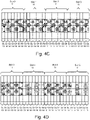
- FIG. 4D is a schematic diagram illustrating one alternate embodiment of data transmission within slots 11.
- four TFR 16a-d are transmitted in four slots 11.
- the TFR number 201 specifies the number of TFR 16.
- FIG. 5A is a schematic diagram illustrating one embodiment of a reserved resource marker 195.
- a transmission control with reserved resource marker 195 is received.
- the reserved resource marker 195 may specify a reserved OFDM symbol 170.
- the reserved OFDM symbols 170 may allow other devices such as mobile device 110 to transmit acknowledgements such as a Hybrid Automatic Repeat Request Acknowledge (HARQ-ACK). Data transmission may be omitted in the reserved OFDM symbols 170 by mobile devices 110 receiving the reserved resource marker 195.
- the reserved OFDM symbol 170 is a last OFDM symbol 10 of a slot 11.
- Figure 5B is a schematic diagram illustrating one alternate embodiment of a reserved resource marker 195.
- a transmission control with reserved resource marker 195 is received.
- the reserved resource bitmap 213 may specify which OFDM symbols 10 and slots 11 include reserved OFDM symbols 170.
- Each reserved OFDM symbol 170 may be reserved for one or more of an uplink communication from mobile devices 110 to the base station 120, a side link communication between mobile devices 120, and a backhaul communication.
- Figure 6A is a schematic diagram illustrating one embodiment of multiple numerologies.
- the numerology scheme 280 specifies a first frequency region definition 281 and the first subcarrier spacing 283 for a first frequency region 0 15.
- the numerology scheme 280 may further specify a second frequency region definition 281 and the second subcarrier spacing 283 for one or more second frequency regions 1-n 15.
- Figure 6B is a schematic diagram illustrating one alternate embodiment of multiple numerologies.
- a first set of slots 11 comprising slot 0 11 is configured with the first numerology scheme 280 and a second set of slots 11 comprising slot 1 11 is configured with a second numerology scheme 280.
- the first set of slots 11 is configured with a first sub-carrier spacing 283 and the second set of slots 11 is configured with a second sub-carrier spacing 283.
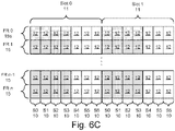
- Figure 6C is a schematic diagram illustrating one alternate embodiment of multiple numerologies.
- a first set of OFDM symbols 0-3 10 is configured with a first numerology scheme 280 and a second set of OFDM symbols 4-6 10 is configured with a second numerology scheme 280.
- the first set of OFDM symbols 10 is configured with a first sub-carrier spacing 283 and the second set of OFDM symbols 10 is configured with a second sub-carrier spacing 283.
- FIG. 7 is a schematic block diagram illustrating one embodiment of a transceiver 400.
- the transceiver 400 may be embodied in the mobile device 110 and/or the base station 120.
- the transceiver 400 includes a processor 405, memory 410, communication hardware 415, a transmitter 420, and receiver 425.
- the memory 410 may include a semiconductor storage device, hard disk drive, an optical storage device, or combinations thereof.
- the memory 410 may store code.
- the processor 405 may execute the code.
- the communication hardware 415 may coordinate communications between the processor 405 and the transmitter 420 and the receiver 425.
- Figure 8A is a schematic flowchart diagram illustrating one embodiment of the scheduling method 500.
- the method 500 may determine available TFR 16 for a data transmission.
- the method 500 may be performed by the transceiver 400 and/or the processor 405 of the transceiver 400.
- the method 500 starts, and in one embodiment, the processor 405 monitors 505 for a transmission control 150/155 in a given OFDM symbol 10 of a first slot 11 based on the symbol position 203 of the transmission control policy 290.
- the transmission control policy 290 may specify one or more OFDM symbols 10 specified by the symbol position 203 and/or one or more frequency ranges 15 specified by the control frequency ranges 204 to monitor 505.
- Figures 2A-I illustrates examples of given OFDM symbols 10 that may be monitored 505.
- slots 11 are monitored for the transmission control 150/155 based on the OFDM symbol duration for a frequency region 15. For example, slots 11 with shorter OFDM symbol durations may be monitored for the transmission control 150/155 in a limited set of given OFDM symbols 10 while slots 11 with longer OFDM symbol durations may be monitored for the transmission control 150/155 in an expanded set of given OFDM symbols 10.
- the processor 405 may receive 510 the transmission control 150/155 in the given OFDM symbol 10.
- the transmission control 150/155 may be a mini-slot transmission control 150 or a slot transmission control 155.
- the processor 405 receives 515 the reserved resources marker 195 with the transmission control 150/155.
- the reserved resources marker 195 may specify a reserved OFDM symbol 170.
- the processor 405 determines 520 the available TFR 16 for the data transmission based on at least a symbol position 203 of the given OFDM symbol 10 and the transmission control policy 290. In one embodiment, the processor 405 omits TFR 16 in the reserved OFDM symbol 170.
- the TFR 16 comprise at least one OFDM symbol 10 and at least one frequency range 15.
- the processor 405 further communicates 525 the transmission data in the TFR 16 and the method 500 ends.
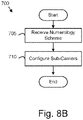
- Figure 8B is a schematic flow chart diagram illustrating one embodiment of a multiple numerology method 700.
- the method 700 configures subcarriers 14 for at least one frequency region 15 based on the numerology scheme 280.
- the method 700 may be performed by the transceiver 400 and/or the processor 405 of the transceiver 400.
- the method 700 starts, and in one embodiment, the processor 405 receives 705 the numerology scheme 280.
- the numerology scheme 280 is received 705 when the mobile device 110 connects with the base station 120.
- the processor 405 further configures 710 the subcarriers 14 for at least one frequency region 15 based on the numerology scheme 280 and the method 700 ends.
- the processor 405 may configure the subcarrier spacing 283 and frequency region definition 281 for the subcarriers 14.
- a 'subframe duration' is 1ms for a reference numerology with 15kHz subcarrier spacing, and 1/2 m ms for reference numerology with 2 m * 15kHz subcarrier spacing.
- 'subframe duration' is defined using a reference numerology
- 'slot 11' and 'mini-slot 17' are defined in terms of the numerology used for transmission.
- the numerology used of transmission of slot/mini-slot can be different from the reference numerology used for determining subframe duration.
- 'Slot 11' and 'mini-slot 17' durations can be characterized as below
- Figure 9 illustrates slot durations 91 and mini-slot durations 94 considering two example subcarrier-spacing values 15kHz and 60kHz.
- a 1 symbol mini-slot allows continuous opportunities to send a transmission control 150/155 such as a Downlink (DL) control to the mobile derive 110, referred to hereafter as UE.
- UE can be configured with a Mini-slot comprising number of OFDM symbols in the numerology used for transmission smaller than the number of OFDM symbols in a slot. It is desirable to minimize the number of supported mini-slot lengths, i.e., support only 1 symbol mini-slot. However, if multiple mini-slot lengths are defined (e.g.
- the UE can be configured with only one mini-slot length at any given time.
- DL control signaling can be sent to the UE once every slot duration. If the UE is configured with a Mini-slot, DL control signaling can be sent to the UE once every mini-slot, in addition to once every slot.
- the opportunities include opportunities to send a slot transmission control 92 and opportunities to send a mini-slot transmission control 93. This is suitable for supporting latency critical traffic applications, and also for operating in spectrum where carrier sense multiple access is needed or desirable (e.g. unlicensed spectrum). Configuring a mini-slot 17 does not necessarily increase overhead (overhead would mainly depend on the resource granularity used for scheduling data transmissions).
- UE control channel decoding complexity can be reduced by having similar control channel transmission structure for slot based and mini-slot based DL control.
- resource allocation granularity i.e., the granularity with which DL/Uplink (UL) resources can be assigned/granted to the UE.
- UL Uplink
- NR resources can be assigned in multiples of Time resource units (TRUs) 95 or mini-TRU 96.
- TRUs Time resource units
- Figure 10 illustrates TRU 95 and mini-TRU 96 that are scheduled via a slot transmission control 92/155 and scheduled via a mini-slot transmission control 93 /150.
- TRUs 95 and mini-TRUs 95 may be characterized as shown.
- UE can be assigned DL/UL resources in multiples of TRUs 95.
- 1TRU corresponds to all available OFDM symbols 10 within one slot 11.
- the UE determines that available OFDM symbols 10 in 3 slots starting from slot 1 (i.e., slots 1,2,3) are assigned to it for DL reception.
- UE can also be configured to receive mini-TRU based DL/UL resource assignments.
- One mini-TRU 95 can correspond to one OFDM symbol 10 in the numerology used for transmission.
- one mini-TRU 96 can correspond another slightly larger value (e.g. 2 or 3 OFDM symbols 10)
- Figure 10 illustrates a few example resource allocations that are possible using TRU based and mini-TRU based resource allocation granularity, and also using slot based and mini-slot based DL control channel transmission.
- mini-slots and mini-TRUs need not be configured for all cases. However, they can be useful to serving UEs with latency critical traffic and also for operation in unlicensed spectrum especially for high load scenarios.
- the figure illustrates DL resource allocations, same definitions are also applicable for uplink. However, for uplink, the time offset between the UL grant and the corresponding uplink transmission (TRU based or mini-TRU based) should also be signaled to the UE.
- resources can be assigned using multiples of PRBs and PRB groups, where a PRB group consists of multiple PRBs (e.g. 4 PRBs or 8PRBs).
- PRB group size can be RRC configured.
- Whether a given resource assignment is assigning resources with TRU granularity or with mini-TRU granularity can be indicated to the UE. This can be indicated explicitly, e.g. via a bit in the control information sent using the DL control channel or implicitly, e.g. using separate identifier (e.g. RNTI) or format for the DL control channels carrying TRU-based and mini-TRU based resource assignments.
- RNTI separate identifier
- whether a given resource assignment is assigning resources with PRB granularity or with PRB-group granularity can be indicated to the UE. This can be indicated explicitly, e.g. via a bit in the control information sent using the DL control channel or implicitly, e.g. using separate identifier (e.g. RNTI) or format for the DL control channels carrying PRB-based and PRB group based resource assignments.
- RNTI separate identifier
- how the UE determines the number of available OFDM symbols within each assigned TRU can depend on whether the DL control channel is sent using slot based control (i.e., at a slot boundary) or whether it is sent using mini-slot based control (i.e., starting at an OFDM symbol that is not aligned with slot boundary).
- the UE determines that OFDM symbols 1-6 10 are available in slot 0 (first assigned TRU) and all OFDM symbols 10 are available in slot 1 11 (2 nd assigned TRU).
- the UE determines that OFDM symbols 3-6 10 are available in slot 0 11(first assigned TRU 95) and all OFDM symbols 10 are available in slot 1 11 (2 nd assigned TRU 95).
- the UE also has to take into account presence of UL resources within a slot while determining the available OFDM symbols 10 of that slot 11 for DL reception.
- UE1 is assigned to receive 3TRUs 95 in via DL control in slot 1
- UE2 is assigned to receive 1 TRU 95 in via DL control in slot 0.
- UE2 transmits the HARQ-ACK corresponding to its received data in the last symbol of slot 1 11.
- that symbol 10 i.e., symbol 6 of slot 1
- One option to provide this information to UE1 is to include some bits in the DL control of UE1 using which the UE can determine the unavailable symbols lOin the slot(s) corresponding to the assigned TRUs 95.
- UE1 is assigned to receive 3TRUs 95 in via DL control in slot 0
- UE2 is assigned to receive 1 TRU 95 in via DL control in slot 1 11.
- UE2 transmits the HARQ-ACK corresponding to its received data in the last symbol 170 of slot 2 11.
- that symbol 170 i.e., symbol 6 of slot 2
- UE1's DL grant is sent before UE2's DL grant, it may not be possible to indicate that symbol 6 of slot 2 is unavailable in UE1's DL grant.
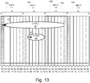
- the marker transmission can be sent typically in the beginning portion of each slot 11 and indicate the symbols used for UL in that slot 11. This is illustrated in Figure 13 where the marker transmission is sent in first symbol 10 of every slot 11. Since the information sent in the marker transmission is rather small (e.g. a 5 or 6-bit bitmap to identify unavailable symbols), the frequency resources used for the marker transmission are expected to be rather limited. e.g. within the first symbol 10 of each slot 11, the marker can be sent is x PRBs (x may be 2, 4, 6 depending cell coverage etc.), where each PRB corresponds to 12 subcarriers.
- the "marker transmission" may not be present in all slots 11-UE assumes all the OFDM symbols 10 in the slot 11 are DL when the marker transmission is not detected.
- the marker transmission design has to be such that it has a very high detection probability when transmitted.
- the marker transmission is sent on a common search space of a control channel with a marker specific RNTI.
- UE is not expected to receive a marker transmission indicating any of the UL symbols as not unavailable symbols.
- the UE assumes the market transmission indicates the worst case unavailable symbols 10, i.e., maximum number of unavailable symbols 10.
- the UE disregards the DL scheduling assignment and restores the HARQ soft buffer for the corresponding HARQ process to it was before it received the DL scheduling assignment, UE may also not transmit a HARQ-ACK feedback.
- TTI transmission time interval
- a "TTI” typically refers to the duration in which the UE can receive/transmit a transport block (TB) 89 from higher layers (i.e., a MAC PDU from MAC layer). Therefore, TTI length depends on how TBs 89 are mapped to TRUs 95/mini-TRUs 96 assigned to the UE.
- TB transport block
- the DL control can include control information and the following can be indicated as part of the control information:
- UE can use a formula or lookup table to determine a TB size for a given #PRBs, #TRUs and MCS combination and then assume that a single TB with that TB size is sent on the time frequency resources corresponding to the #PRBs and #TRUs allocation indicated in the control information.
- TTI duration for the TB 89 is given by the duration of all indicated TRUs 95.
- Figure 14 shows an example for this case.
- UE can use a formula or lookup table to determine a TB size for a given #PRBs and MCS combination, and then assume that a multiple TBs 89 with that TB size (e.g. one TB for each TRU 95 in the #TRUs indicated) are sent on the time frequency resources corresponding to the #PRBs and #TRUs allocation indicated in the control information 87.
- the multiple TBs can include repetition of one or more TBs.
- TTI duration for each TB 89 is given by the duration of each TRU 95 on which the TB 89 is sent.
- Figure 15 shows an example for this case.
- UE can use a formula or lookup table to determine a TB size for a given #PRBs and MCS combination, and then transmit/receive x TBs with the determined TB size on the time frequency resources corresponding to the #PRBs and #TRUs allocation indicated in the control information.
- transmission of some of the TBs can start in one slot corresponding to a first allocated TRU 95 and end in the middle of a later slot corresponding to a later allocated TRU 95 later than the first allocated TRU 95.
- Figure 16 shows an example for this case.
- the DL control can include control information and the following can be indicated as part of the control information:
- UE can determine a transport block size from the TB index value, and a transmit/receive a single TB 89 (e.g. similar to Figure 14 ) with that TB size on the time frequency resources corresponding to the #PRBs and #TRUs allocation indicated in the control information.
- UE can use a formula or look up table to determine the MCS value used for transmission/reception of the transport block for a given TB size, #PRBs and #TRUs combination.
- UE can determine a transport block size from the TB index value, and a transmit/receive multiple TBs (e.g. one TB for each TRU in the #TRUs indicated as shown in Figure 15 ) with that TB size on the time frequency resources corresponding to the #PRBs and #TRUs allocation indicated in the control information.
- UE can use a formula or look up table to determine the MCS value used for transmission/reception of the transport block for a given TB size, #PRBs combination.
- UE can determine a transport block size from the TB index value, and then transmit/receive x TBs with the determined TB size on the time frequency resources corresponding to the #PRBs and #TRUs allocation indicated in the control information. In this case, it is possible that transmission of some of the TBs can start in one slot corresponding to a first allocated TRU 95 and end in the middle of a later slot corresponding to a later allocated TRU 95 later than the first allocated TRU 95. UE can use a formula or look up table to determine the MCS value used for transmission/reception of the transport block for a given TB size, #PRBs, #TRUs, #TBs combination.
- the control information in the transmission control 93 may include a number of mini-TRUs 96 (#mini-TRUs) instead of #TRUs. In that case, UE can use #mini-TRUs value in place of #TRUs.
- the control information may include a number of PRB groups (#PRB-groups) instead of #PRBs. In that case, UE can #PRB-groups value in place of #PRBs.
- the system should support an operation mode where (time domain) resources reserved for UL are semi-statically indicated to the UE. Similar to semi-static reservation of UL resources, it should also be possible to semi-statically reserve time domain resources for other transmissions such as sidelink transmissions or backhaul transmissions. From a DL reception perspective, the UE can consider OFDM symbols 10 corresponding to reserved resources (for UL or other purposes) are considered as unavailable for DL data transmission if the assigned TRUs for the UE overlap the reserved resources.
- Another flexible and forward compatible approach for supporting UL transmissions is to let UE determine its UL transmission resources based on information received in L1 DL control signaling.
- TRUs 95/mini-TRUs 96 that the UE should use can be signaled in the UL grant along with the time offset between the UL grant and the allocated TRUs.
- the timing for HARQ-ACK depends on the end point of DL data transmission and time-frequency mapping of the DL TBs. Also, the number of TRUs 95/mini-TRUs 96 required for HARQ-ACK transmission depends on several factors including UE coverage and latency requirements. Considering these aspects, the system should also support an operation mode where no UL resources are pre-reserved using semi-static signaling.
- a UE may be configured to monitor the slot and mini-slot occurrences (e.g. attempt to decode slot based DL control and/or mini-slot based DL control) in different frequency regions of a carrier in a given time interval with each frequency region having its own numerology and subcarrier spacing.
- slot and mini-slot occurrences e.g. attempt to decode slot based DL control and/or mini-slot based DL control
- a UE may be configured to monitor the slot and mini-slot occurrences (e.g. attempt to decode slot-based DL control and/or mini-slot based DL control) in different frequency regions in each carrier over multiple carriers in a given time interval with each frequency region having its own numerology and subcarrier spacing.
- slot and mini-slot occurrences e.g. attempt to decode slot-based DL control and/or mini-slot based DL control
- the UE may be configured to only monitor a subset of all possible slot and mini-slot occurrences in each frequency region to reduce the overall required control and data decoding attempts for the given time interval.
- DCI format of the DL control provides a compressed resource allocation indication for narrow band allocation.
- the UE configured to monitor control channel with a first dedicated control channel indicator format.
- the first dedicated control channel indicator format including an indication of a sub-band starting position.
- the UE is provided with resource allocation within a sub-portion of the wideband channel and the DCI indicates which sub-band this is.
- resource allocation can begin in any slot 11 and in any mini-slot location of the indicated slot.
- the control channel indicator can include the starting slot location for allocation.
- the Control channel indicator includes the starting slot location for allocation (so UE can receive control channel in slot other than the beginning slot of allocation).
- aggregation of DL control resources across mini-slots is configured to determine the downlink control information.
- the receiving control the control channel information can further include a frequency diverse allocation field consisting of a single bit indicating frequency diverse allocations for the resource assignments; the frequency diverse allocation determined by one or more of the resource allocation fields, a priori information, and using signaling other than the control channel, the a priori information comprising the contents of a look-up table the signaling other than the control channel comprises high layer signaling to indicate which sub-frames of the continuum of concatenated sub-frames are included in the frequency diverse allocation.
- the plurality of resource allocation fields indicating a resource assignment to the wireless communication device.
- UE may be configured to monitor first mini-slot of slot or every mini-slot of slot.
- the resource allocation information indicates the Start of the first mini-slot, number of slots or it could be a fixed number of mini-slots from the mini-slot containing the PDCCH providing resource allocation.
- the Resource allocation information can indicate the number of slots for which the allocation is valid, including the number of mini-slots in the last slot of allocation. In this case the resource allocation or time resource unit need not align with the end of the slot boundary.
- a method in a wireless communication device comprising:
- receiving a plurality of slots further comprising, the slot includes a continuum of mini-slots, a mini-slot composed of a second number of OFDM symbols, the second number is less than the first number of OFDM symbols
- the method of claim 1a further comprising, configuring the communication device to monitor the first symbol of each mini-slot
- Method of claim 1b where the UE Is configured to monitor the first symbol of a sub-set of mini-slots, the subset of mini-slots not including every mini-slot in the continuum of mini-slots
- control channel information including the location (identity of symbols) of uplink resources that overlap the time resource units assigned to the UE
- the marker information including, identity of symbols used for (or presence or lack thereof) of uplink resources in the corresponding slot
- Determining the available OFDM symbols based on the identity of symbols used for uplink resource the determining including removing the symbols used for uplink resource from the available OFDM symbols receiving data based in the resource allocation in the decoded control channel and the available OFDM symbols.
- a method in a wireless communication device or UE comprising receiving a configuration message, the configuration message configuring the UE to monitor on a first carrier a first subset of slot and mini-slot occasions, and further configuring the UE to monitor on a second carrier a second subset of slot and mini-slot occasions wherein each slot occasion comprises a first number of OFDM symbol durations and each mini-slot occasion comprises a second number of OFDM symbol durations and the second number is smaller than the first number.
- first subset of slot and mini-slots occasions correspond to a first numerology and sub-carrier spacing and the second subset of slot and mini-slot occasions correspond to a second numerology and subcarrier spacing.
- a method in a wireless communication device or UE comprising receiving a configuration message, the configuration message configuring the UE to monitor in each frequency region of a plurality of frequency regions, a subset of available slot and mini-slot occasions wherein each slot occasion comprises a first number of OFDM symbol durations and each mini-slot occasion comprises a second number of OFDM symbol durations and the second number is smaller than the first number, where the plurality of frequency regions may be in one carrier or mapped to more than one carrier.
- each subset of slot and mini-slots occasions corresponds to a different numerology and sub-carrier spacing.
- An apparatus comprising:
- the transmission control is one of a downlink control for a downlink data transmission to a mobile device and an uplink control for an uplink data transmission to a base station.
- the transmission control policy specifies that the symbol position of the given OFDM symbol is OFDM symbol 0 for a slot transmission control, the symbol position is of one or more of OFDM symbols 1-13 for a 14-symbol mini-slot transmission control, and the symbol position is one or more of OFDM symbols 1-6 for a seven-symbol mini-slot transmission control.
- the transmission control policy specifies that the symbol position of the given OFDM symbol is OFDM symbols 0-1 for a slot transmission control, the symbol position of the given OFDM symbol is selected from the group of consisting of OFDM symbol 2, OFDM symbol 4, OFDM symbol 6, OFDM symbol 8, OFDM symbol 10, and OFDM symbol 12 for a 14-symbol mini-slot transmission control, and the symbol position of the given OFDM symbol is selected from the group of consisting of OFDM symbol 2, OFDM symbol 4, and OFDM symbol 6 for a seven-symbol mini-slot transmission control.
- the transmission control policy specifies that the symbol position of the given OFDM symbol is OFDM symbols 0-1 for a slot transmission control, the symbol position of the given OFDM symbol is one or more of OFDM symbols 1-6 for a seven-symbol mini-slot transmission control, and the symbol position of the given OFDM symbol is one or more of OFDM symbols 1-13 for a 14-symbol mini-slot transmission control, wherein a slot type indicator determines whether the transmission control in OFDM symbol 1 is a slot transmission control 155 or a mini-slot transmission control.
- the transmission control policy specifies that the symbol position of the given OFDM symbol is OFDM symbols 0-2 for a slot transmission control, the symbol position of the given OFDM symbol is one or more of OFDM symbols 1-13 for a 14-symbol mini-slot transmission control, and the symbol position of the given OFDM symbol is one or more of OFDM symbols 1-6 for a seven-symbol mini-slot transmission control, wherein a slot type indicator determines whether the transmission control in OFDM symbols 1 and 2 is a slot transmission control or a mini-slot transmission control.
- the transmission control policy specifies that the symbol position of the given OFDM symbol is OFDM symbols 0-2 for a slot transmission control, the symbol position of the given OFDM symbol is selected from the group of consisting of OFDM symbol 2, OFDM symbol 4, OFDM symbol 6, OFDM symbol 8, OFDM symbol 10, and OFDM symbol 12 for a 14-symbol mini-slot transmission control, and the symbol position of the given OFDM symbol is selected from the group of consisting of OFDM symbol 2, OFDM symbol 4, and OFDM symbol 6 for a seven-symbol mini-slot transmission control, wherein a slot type indicator determines whether the transmission control in OFDM symbol 2 is a slot transmission control or a mini-slot transmission control.
- a first TFR of the TFR starts at an OFDM symbol immediately following the given OFDM symbol and ends at OFDM symbol 13 of a 14-symbol slot and ends at OFDM symbol 6 of a seven-symbol slot.
- the transmission control comprises a TFR number that specifies a number of TFR in the data transmission and wherein for a given TFR number that is greater than one, the TFR end at a last OFDM symbol of a slot subsequent to the first slot and wherein the TFR comprise the TFR number of TFR transmitted in the number of TFR slots.
- TFR is a mini-TFR that starts at an OFDM symbol immediately following the given OFDM symbol and comprises 2 to 12 OFDM symbols.
- the transmission control comprises a modulation encoding scheme (MCS) index that specifies a modulation scheme and an encoding rate and the TFR are determined based on the modulation scheme and the encoding rate.
- MCS modulation encoding scheme
- the transmission control further comprising a starting slot indicator that specifies an initial slot for the data transmission.
- the reserved resources marker 195 comprises a reserved resources bitmap with a bit set for each reserved OFDM symbol in one or more slots.
- each reserved OFDM symbol is reserved for one or more of an uplink communication, a side link communication and a back-off communication.
- Radio frequency bandwidths are valuable. As a result, it is advantageous to minimize the use of bandwidth.
- the embodiments described herein employ mini slots 17 to reduce the bandwidth resources required in communications between the base station 120 and a mobile device 110.
- the embodiments determine available TFR 16 for a data transmission based at least in part on the symbol position 203 of a given OFDM symbol 10 that carries the transmission control 150/155. As a result, transmission control data bits may be conserved.
- Embodiments may be practiced in other specific forms. The described may be performed by a processor. Embodiments are to be considered in all respects only as illustrative and not restrictive. The scope of the invention is, therefore, indicated by the appended claims rather than by the foregoing description. All changes which come within the meaning and range of equivalency of the claims are to be embraced within their scope.
Abstract
Description
- This application claims priority to
United States Provisional Patent Application 62/403,022 entitled "FLEXIBLE RADIO RESOURCE ALLOCATION METHODS" and filed on September 30, 2016 for Robert Love - The subject matter disclosed herein relates to resource allocation and more particularly relates to flexible radio resource allocation.
- Long Term Evolution (LTE) and other wireless communication standards may subdivide transmissions to efficient use available bandwidth.
- A method for flexible radio resource allocation is disclosed. The method monitors, by use of a processor, for a transmission control in a given Orthogonal Frequency-Division Multiplexing (OFDM) symbol of a first slot based on a transmission control policy. The method further receives the transmission control in the given OFDM symbol. The method determines available time frequency resources (TFR) for a data transmission based on at least a symbol position of the given OFDM symbol and the transmission control policy, wherein the TFR comprise at least one OFDM symbol and at least one frequency range. The method communicates the data transmission in the TFR. An apparatus and program product also perform the functions of the method.
- A more particular description of the embodiments briefly described above will be rendered by reference to specific embodiments that are illustrated in the appended drawings. Understanding that these drawings depict only some embodiments and are not therefore to be considered to be limiting of scope, the embodiments will be described and explained with additional specificity and detail through the use of the accompanying drawings, in which:
-
Figure 1A is a schematic block diagram illustrating one embodiment of a communication system; -
Figure 1B is a schematic block diagram illustrating one embodiment of a 14-symbol slot; -
Figure 1C is a schematic block diagram illustrating one embodiment of seven-symbol slots; -
Figure 1D is a schematic block diagram illustrating one embodiment of a 14-symbol slot; -
Figure 1E is a schematic block diagram illustrating one embodiment of seven-symbol slots; -
Figure 1F is a schematic block diagram illustrating one embodiment of time frequency resources data; -
Figure 1G is a schematic block diagram illustrating one embodiment of a transmission control; -
Figure 1H is a schematic block diagram illustrating one embodiment of a modulation encoding scheme index; -
Figure 1I is a schematic block diagram illustrating one embodiment of a transport block index; -
Figure 1J is a schematic block diagram illustrating one embodiment of a numerology scheme; -
Figure 1K is a schematic block diagram illustrating one embodiment of a transmission control policy; -
Figure 2A is a schematic diagram illustrating one embodiment of transmission controls within slots; -
Figure 2B is a schematic diagram illustrating one alternate embodiment of transmission controls within slots; -
Figure 2C is a schematic diagram illustrating one alternate embodiment of transmission controls within slots; -
Figure 2D is a schematic diagram illustrating one alternate embodiment of transmission controls within slots; -
Figure 2E is a schematic diagram illustrating one alternate embodiment of transmission controls within slots; -
Figure 2F is a schematic diagram illustrating one embodiment of transmission controls within slots; -
Figure 2G is a schematic diagram illustrating one alternate embodiment of transmission controls within slots; -
Figure 2H is a schematic diagram illustrating one alternate embodiment of transmission controls within slots; -
Figure 2I is a schematic diagram illustrating one alternate embodiment of transmission controls within slots; -
Figure 3A is a schematic diagram illustrating one embodiment of data transmission within slots; -
Figure 3B is a schematic diagram illustrating one alternate embodiment of data transmission within slots; -
Figure 3C is a schematic diagram illustrating one alternate embodiment of data transmission within slots; -
Figure 3D is a schematic diagram illustrating one alternate embodiment of data transmission within slots; -
Figure 3E is a schematic diagram illustrating one alternate embodiment of data transmission within slots; -
Figure 3F is a schematic diagram illustrating one alternate embodiment of data transmission within slots; -
Figure 3G is a schematic diagram illustrating one alternate embodiment of data transmission within slots; -
Figure 3H is a schematic diagram illustrating one alternate embodiment of data transmission within slots; -
Figure 3I is a schematic diagram illustrating one embodiment of data transmission; -
Figure 4A is a schematic diagram illustrating one alternate embodiment of data transmission within slots; -
Figure 4B is a schematic diagram illustrating one alternate embodiment of data transmission within slots; -
Figure 4C is a schematic diagram illustrating one alternate embodiment of data transmission within slots; -
Figure 4D is a schematic diagram illustrating one alternate embodiment of data transmission within slots; -
Figure 5A is a schematic diagram illustrating one embodiment of a resource marker; -
Figure 5B is a schematic diagram illustrating one alternate embodiment of a resource marker; -
Figure 6A is a schematic diagram illustrating one embodiment of multiple numerologies; -
Figure 6B is a schematic diagram illustrating one alternate embodiment of multiple numerologies; -
Figure 6C is a schematic diagram illustrating one alternate embodiment of multiple numerologies; -
Figure 7 is a schematic block diagram illustrating one embodiment of a transceiver; -
Figure 8A is a schematic flowchart diagram illustrating one embodiment of the scheduling method; -
Figure 8B is a schematic flow chart diagram illustrating one embodiment of a multiple numerology method; -
Figure 9 is a schematic diagram illustrating one embodiment of slots; -
Figure 10 is a schematic diagram illustrating one embodiment of time resource units and mini-time resource units; -
Figure 11 is a schematic diagram illustrating one embodiment of time resource units; -
Figure 12 is a schematic diagram illustrating one embodiment of time resource units; -
Figure 13 is a schematic diagram illustrating one embodiment of time resource units; -
Figure 14 is a schematic diagram illustrating one embodiment of a transport block data transmission within slots; -
Figure 15 is a schematic diagram illustrating one embodiment of transport blocks data transmission within slots; and -
Figure 16 is a schematic diagram illustrating one embodiment of transport blocks data transmission within slots. - As will be appreciated by one skilled in the art, aspects of the embodiments may be embodied as a system, method or program product. Accordingly, embodiments may take the form of an entirely hardware embodiment, an entirely software embodiment (including firmware, resident software, micro-code, etc.) or an embodiment combining software and hardware aspects that may all generally be referred to herein as a "circuit," "module" or "system." Furthermore, embodiments may take the form of a program product embodied in one or more computer readable storage devices storing machine readable code, computer readable code, and/or program code, referred hereafter as code. The storage devices may be tangible, non-transitory, and/or non-transmission. The storage devices may not embody signals. In a certain embodiment, the storage devices only employ signals for accessing code.
- Many of the functional units described in this specification have been labeled as modules, in order to more particularly emphasize their implementation independence. For example, a module may be implemented as a hardware circuit comprising custom VLSI circuits or gate arrays, off-the-shelf semiconductors such as logic chips, transistors, or other discrete components. A module may also be implemented in programmable hardware devices such as field programmable gate arrays, programmable array logic, programmable logic devices or the like.
- Modules may also be implemented in code and/or software for execution by various types of processors. An identified module of code may, for instance, comprise one or more physical or logical blocks of executable code which may, for instance, be organized as an object, procedure, or function. Nevertheless, the executables of an identified module need not be physically located together, but may comprise disparate instructions stored in different locations which, when joined logically together, comprise the module and achieve the stated purpose for the module.
- Indeed, a module of code may be a single instruction, or many instructions, and may even be distributed over several different code segments, among different programs, and across several memory devices. Similarly, operational data may be identified and illustrated herein within modules, and may be embodied in any suitable form and organized within any suitable type of data structure. The operational data may be collected as a single data set, or may be distributed over different locations including over different computer readable storage devices. Where a module or portions of a module are implemented in software, the software portions are stored on one or more computer readable storage devices.
- Any combination of one or more computer readable medium may be utilized. The computer readable medium may be a computer readable storage medium. The computer readable storage medium may be a storage device storing the code. The storage device may be, for example, but not limited to, an electronic, magnetic, optical, electromagnetic, infrared, holographic, micromechanical, or semiconductor system, apparatus, or device, or any suitable combination of the foregoing.
- More specific examples (a non-exhaustive list) of the storage device would include the following: an electrical connection having one or more wires, a portable computer diskette, a hard disk, a random-access memory (RAM), a read-only memory (ROM), an erasable programmable read-only memory (EPROM or Flash memory), a portable compact disc read-only memory (CD-ROM), an optical storage device, a magnetic storage device, or any suitable combination of the foregoing. In the context of this document, a computer readable storage medium may be any tangible medium that can contain, or store a program for use by or in connection with an instruction execution system, apparatus, or device.
- Code for carrying out operations for embodiments may be written in any combination of one or more programming languages including an object-oriented programming language such as Python, Ruby, Java, Smalltalk, C++, or the like, and conventional procedural programming languages, such as the "C" programming language, or the like, and/or machine languages such as assembly languages. The code may execute entirely on the user's computer, partly on the user's computer, as a stand-alone software package, partly on the user's computer and partly on a remote computer or entirely on the remote computer or server. In the latter scenario, the remote computer may be connected to the user's computer through any type of network, including a local area network (LAN) or a wide area network (WAN), or the connection may be made to an external computer (for example, through the Internet using an Internet Service Provider).
- Reference throughout this specification to "one embodiment," "an embodiment," or similar language means that a particular feature, structure, or characteristic described in connection with the embodiment is included in at least one embodiment. Thus, appearances of the phrases "in one embodiment," "in an embodiment," and similar language throughout this specification may, but do not necessarily, all refer to the same embodiment, but mean "one or more but not all embodiments" unless expressly specified otherwise. The terms "including," "comprising," "having," and variations thereof mean "including but not limited to," unless expressly specified otherwise. An enumerated listing of items does not imply that any or all of the items are mutually exclusive, unless expressly specified otherwise. The terms "a," "an," and "the" also refer to "one or more" unless expressly specified otherwise.
- Furthermore, the described features, structures, or characteristics of the embodiments may be combined in any suitable manner. In the following description, numerous specific details are provided, such as examples of programming, software modules, user selections, network transactions, database queries, database structures, hardware modules, hardware circuits, hardware chips, etc., to provide a thorough understanding of embodiments. One skilled in the relevant art will recognize, however, that embodiments may be practiced without one or more of the specific details, or with other methods, components, materials, and so forth. In other instances, well-known structures, materials, or operations are not shown or described in detail to avoid obscuring aspects of an embodiment.
- Aspects of the embodiments are described below with reference to schematic flowchart diagrams and/or schematic block diagrams of methods, apparatuses, systems, and program products according to embodiments. It will be understood that each block of the schematic flowchart diagrams and/or schematic block diagrams, and combinations of blocks in the schematic flowchart diagrams and/or schematic block diagrams, can be implemented by code. The code may be provided to a processor of a general-purpose computer, special purpose computer, or other programmable data processing apparatus to produce a machine, such that the instructions, which execute via the processor of the computer or other programmable data processing apparatus, create means for implementing the functions/acts specified in the schematic flowchart diagrams and/or schematic block diagrams block or blocks.
- The code may also be stored in a storage device that can direct a computer, other programmable data processing apparatus, or other devices to function in a particular manner, such that the instructions stored in the storage device produce an article of manufacture including instructions which implement the function/act specified in the schematic flowchart diagrams and/or schematic block diagrams block or blocks.
- The code may also be loaded onto a computer, other programmable data processing apparatus, or other devices to cause a series of operational steps to be performed on the computer, other programmable apparatus or other devices to produce a computer implemented process such that the code which execute on the computer or other programmable apparatus provide processes for implementing the functions/acts specified in the flowchart and/or block diagram block or blocks.
- The schematic flowchart diagrams and/or schematic block diagrams in the Figures illustrate the architecture, functionality, and operation of possible implementations of apparatuses, systems, methods and program products according to various embodiments. In this regard, each block in the schematic flowchart diagrams and/or schematic block diagrams may represent a module, segment, or portion of code, which comprises one or more executable instructions of the code for implementing the specified logical function(s).
- It should also be noted that, in some alternative implementations, the functions noted in the block may occur out of the order noted in the Figures. For example, two blocks shown in succession may, in fact, be executed substantially concurrently, or the blocks may sometimes be executed in the reverse order, depending upon the functionality involved. Other steps and methods may be conceived that are equivalent in function, logic, or effect to one or more blocks, or portions thereof, of the illustrated Figures.
- Although various arrow types and line types may be employed in the flowchart and/or block diagrams, they are understood not to limit the scope of the corresponding embodiments. Indeed, some arrows or other connectors may be used to indicate only the logical flow of the depicted embodiment. For instance, an arrow may indicate a waiting or monitoring period of unspecified duration between enumerated steps of the depicted embodiment. It will also be noted that each block of the block diagrams and/or flowchart diagrams, and combinations of blocks in the block diagrams and/or flowchart diagrams, can be implemented by special purpose hardware-based systems that perform the specified functions or acts, or combinations of special purpose hardware and code.
- The description of elements in each figure may refer to elements of proceeding figures. Like numbers refer to like elements in all figures, including alternate embodiments of like elements.
-
Figure 1A is a schematic block diagram illustrating one embodiment of acommunication system 100. Thesystem 100 includes one or more base stations 120 and one or more mobile devices 110. The mobile devices 110 may communicate with the base stations 120. A base station 120 may be a gNodeB (gNB) base station 120, i.e. New Radio (NR) base station 120, or an enhanced evolved node B (eNB) Long Term Evolution (LTE) base station 120. The mobile device 110 may be a mobile telephone, a machine-type communications (MTC) device, a tablet computer, a laptop computer, and embedded communication devices in automobiles, kiosks, appliances, and the like. - The
system 100 may communicate a downlink control to specify the available time frequency resources (TFR) for a downlink data transmission to the mobile device 110. In addition, thesystem 100 may communicate an uplink control to specify the available time frequency resources (TFR) for an uplink data transmission to a base station 120. The downlink control and the uplink control are collectively referred to hereafter as a transmission control. The embodiments described herein determine the available TFR based in part on a position of an Orthogonal Frequency-Division Multiplexing (OFDM) symbol as will be described hereafter. OFDM in general comprises regular OFDM, pre-coded OFDM such as DFT-spread OFDM (DFT-SOFDM), or Single-carrier FDM (SC-FDM). In addition, thesystem 100 may configure subcarriers for communications between the base stations 120 and the mobile devices 110 as will be described hereafter. -
Figure 1B is a schematic block diagram illustrating one embodiment of a 14-symbol slot 11. Theslot 11 is a time- and frequency-based unit of communication between the base stations 120 and the mobile devices 110. In the depicted embodiment, theslot 11 includes 14 time-basedOFDM symbols 10 and a plurality of frequency-basedsubcarriers 14 for eachOFDM symbol 10. Each combination of asub carrier 14 and anOFDM symbol 10 forms aresource element 12. -
Figure 1C is a schematic block diagram illustrating one embodiment of seven-symbol slots 11. In the depicted embodiment, twoslots 11 are shown. Eachslot 11 includes sevenOFDM symbols 10. Each combination of asub carrier 14 and anOFDM symbol 10 forms aresource element 12. -
Figure 1D is a schematic block diagram illustrating one embodiment of a 14-symbol slot 11. In the depicted embodiment, the frequencies of eachOFDM symbol 10 is divided into a plurality of frequency ranges or frequency resources (FR) A frequency range or resource comprises a plurality of subcarriers, with different frequency ranges having the same or different number of subcarriers. 15. Each combination of anOFDM symbol 10 and afrequency range 15 forms aTFR 16. - The
slot 11 may include one or more mini-slots 17. Each mini-slots 17 may include one ormore OFDM symbols 10, including eachfrequency range 15 for eachOFDM symbol 10. In the depicted embodiment, one and twoOFDM symbol mini-slots 17 are shown. A mini-slot 17 in a 14-symbol slot 11 may comprise from 1 to 13OFDM symbols 10. -
Figure 1E is a schematic block diagram illustrating one embodiment of seven-symbol slots 11. In the depicted embodiment, twoslots 11 withmini-slots 17 are shown. The mini-slots 17 include one ormore OFDM symbols 10, including eachfrequency range 15 for eachOFDM symbol 10. In the depicted embodiment, one and twoOFDM symbol mini-slots 17 are shown. A mini-slot 17 in a seven-symbol slot 11 may comprise from 1 to 6OFDM symbols 10. -
Figure 1F is a schematic block diagram illustrating one embodiment ofTFR data 200. TheTFR data 200 may describe anavailable TFR 16. TheTFR data 200 maybe organized as a data structure in a memory and/or encoded for transmission. In the depicted embodiment, theTFR data 200 includes aTFR number 201, asymbol position 203, and a slot type indicator 205. TheTFR number 201 may specify a number ofTFR 16 in a data transmission. In one embodiment, theTFR number 201 is greater than one. Thesymbol position 203 may indicate a position of a givenOFDM symbol 10 that includes a transmission control. The slot type indicator 205 may determine whether a transmission control is a slot transmission control or a mini-slot transmission control. -
Figure 1G is a schematic block diagram illustrating one embodiment of atransmission control 150/155. Thetransmission control 150/155 may be one of aslot transmission control 155 and amini-slot transmission control 150. Thetransmission control 150/155 maybe organized as a data structure in a memory and/or encoded for transmission. In the depicted embodiment, thetransmission control 150/155 includes the startingslot indicator 211, areserved resources marker 195, and a reserved resources bitmap 213. The startingslot indicator 211 may specify aninitial slot 11 for a data transmission. The reservedresources marker 195 may indicate areserved OFDM symbol 10. In one embodiment, a mobile device 110 is prevented from receiving or transmitting data in thereserved OFDM symbol 10. The reserved resources bitmap 213 may specify whichslots 11 have a reservedOFDM symbol 10. In addition, the reserved resources bitmap 213 may have a bit set for each reserved OFDM symbol in one ormore slots 11. -
Figure 1H is a schematic block diagram illustrating one embodiment of a modulationencoding scheme index 220. The modulationencoding scheme index 220 maybe organized as a data structure and/or encoded for transmission. In the depicted embodiment, themodulation encoding scheme 220 includes amodulation scheme 221 and anencoding rate 223. Themodulation scheme 221 may specify the QAM modulation order to use for the resource allocated in frequency ranges 15 and/orsubcarriers 14 for eachslot 11,OFDM symbols 10 of aslot 11, and/or frequency ranges 15 with aslot 11. Theencoding rate 223 may specify the rate at whichTFR 16 are encoded. Themodulation scheme 221 and theencoding rate 223 may be jointly encoded. The transport block size on the allocatedTFR 16 may be determined based on themodulation scheme 221 and theencoding rate 223. -
Figure 1I is a schematic block diagram illustrating one embodiment of atransport block index 230. Thetransport block index 230 may be organized as a data structure in a memory and/or encoded for transmission. In the depicted embodiment, thetransport block index 230 includes atransport block size 231, aTB TFR number 232, and a physical resource Block (PRB)number 233. Thetransport block size 231 may indicate a size of a transport block in a data transmission. TheTB TFR number 232 may specify a number ofTFR 16 in the time-domain in a data transmission. ThePRB number 233 may specify a number of PRB in the data transmission. -
Figure 1J is a schematic block diagram illustrating one embodiment of anumerology scheme 280. Thenumerology scheme 280 maybe organized as a data structure in a memory and/or encoded for transmission. In the depicted embodiment, thenumerology scheme 280 includes afrequency region definition 281 and asubcarrier spacing 283. Thefrequency range definition 281 may define one or more frequency ranges 15. Thesubcarrier spacing 283 may specify a spacing betweensubcarriers 14 for one ormore frequency regions 15. -
Figure 1K is a schematic block diagram illustrating one embodiment of atransmission control policy 290. Thetransmission control policy 290 maybe organized as a data structure in a memory and/or encoded for transmission. In the depicted embodiment, thetransmission control policy 290 includes thesymbol position 203, control frequency ranges 204, and the slot type indicator 205. The control frequency ranges 204 may specify one or more frequency ranges 15 that include thetransmission control 150/155. -
Figure 2A is a schematic diagram illustrating one embodiment of transmission controls 150/155 withinslots 11. In the depicted embodiment, 14-symbol slots 11 and seven-symbol slots 11 are shown. Thetransmission policy 290 may specify that thesymbol position 203 of a givenOFDM symbol 10 that includes thetransmission control 150/155 isOFDM symbol 0 10 for aslot transmission control 155 in the 14-symbol slot 11 and the seven-symbol slot 11. Thesymbol position 203 may be of one or more of OFDM symbols 1-13 10 for a 14-symbolmini-slot transmission control 150 in the 14-symbol slot 11. Thesymbol position 203 may be one or more of OFDM symbols 1-6 10 for a seven-symbolmini-slot transmission control 150 of the seven-symbol slot 11. - In one embodiment, the given
OFDM symbol 10 comprises amini-slot transmission control subsequent OFDM symbols 10 comprise a mini-slot 17 for a 14-symbol slot 11. In addition, the givenOFDM symbol 10 may comprise amini-slot transmission control subsequent OFDM symbols 10 comprise a mini-slot 17 for a seven-symbol slot 11. -
Figure 2B is a schematic diagram illustrating one alternate embodiment of transmission controls 150/155 withinslots 11. In the depicted embodiment, 14-symbol slots 11 and seven-symbol slots 11 are shown. Thetransmission policy 290 may specify that thesymbol position 203 of a givenOFDM symbol 10 that includes thetransmission control 150/155 is OFDM symbols 0-1 10 for aslot transmission control 155 in the 14-symbol slot 11 and the seven-symbol slot 11. Thesymbol position 203 of the givenOFDM symbol 10 may be selected from the group of consisting ofOFDM symbol 2 10,OFDM symbol 4 10,OFDM symbol 6 10, OFDM symbol 8 10,OFDM symbol 10 10, andOFDM symbol 12 10 for a 14-symbolmini-slot transmission control 150 in the 14-symbol slot 11. Thesymbol position 203 of the given OFDM symbol may be selected from the group of consisting ofOFDM symbol 2 10,OFDM symbol 4 10, andOFDM symbol 6 10 for a seven-symbolmini-slot transmission control 150 in the seven-symbol slot 11. -
Figure 2C is a schematic diagram illustrating one alternate embodiment of transmission controls 150/155 withinslots 11. In the depicted embodiment, 14-symbol slots 11 and seven-symbol slots 11 are shown. Thetransmission control policy 290 may specify that thesymbol position 203 of the givenOFDM symbol 10 is OFDM symbols 0-1 10 for aslot transmission control 155 in the 14-symbol slot 11 and the seven-symbol slot 11. Thesymbol position 203 of the givenOFDM symbol 10 may be one or more of OFDM symbols 1-6 10 for a seven-symbolmini-slot transmission control 150 in the seven-symbol slot 11. Thesymbol position 203 of the givenOFDM symbol 10 is one or more of OFDM symbols 1-13 10 for a 14-symbolmini-slot transmission control 150 in the 14-symbol slot 11. The slot type indicator 205 may determine whether thetransmission control 190 inOFDM symbol 1 10 is aslot transmission control 155 or amini-slot transmission control 150. -
Figure 2D is a schematic diagram illustrating one alternate embodiment of transmission controls 150/155 withinslots 11. In the depicted embodiment, 14-symbol slots 11 and seven-symbol slots 11 are shown. Thetransmission control policy 290 may specify that thesymbol position 203 of the givenOFDM symbol 10 is OFDM symbols 0-2 10 for aslot transmission control 155 in the 14-symbol slot 11 and the seven-symbol slot 11. Thesymbol position 203 of the givenOFDM symbol 10 may be one or more of OFDM symbols 1-13 10 for a 14-symbolmini-slot transmission control 150 in the 14-symbol slot 11. Thesymbol position 203 of the givenOFDM symbol 10 may be one or more of OFDM symbols 1-6 10 for a seven-symbolmini-slot transmission control 150 in a seven-symbol slot 11. The slot type indicator 205 may determine whether thetransmission control 190 inOFDM symbols slot transmission control 155 or amini-slot transmission control 150. -
Figure 2E is a schematic diagram illustrating one alternate embodiment of transmission controls 150/155 withinslots 11. In the depicted embodiment, 14-symbol slots 11 and seven-symbol slots 11 are shown. Thetransmission control policy 290 may specify that thesymbol position 203 of the givenOFDM symbol 10 is OFDM symbols 0-2 10 for aslot transmission control 155 in the 14-symbol slot 11 and the seven-symbol slot 11. Thesymbol position 203 of the givenOFDM symbol 10 may be selected from the group of consisting ofOFDM symbol 2 10,OFDM symbol 4 10,OFDM symbol 6 10, OFDM symbol 8 10,OFDM symbol 10 10, andOFDM symbol 12 10 for a 14-symbolmini-slot transmission control 150 in the 14-symbol slot 11. Thesymbol position 203 of the givenOFDM symbol 10 may be selected from the group of consisting ofOFDM symbol 2 10,OFDM symbol 4 10, andOFDM symbol 6 10 for a seven-symbolmini-slot transmission control 150 in the seven-symbol slot 11. The slot type indicator 205 may determine whether thetransmission control 190 inOFDM symbol 2 10 is aslot transmission control 155 or amini-slot transmission control 150. -
Figure 2F is a schematic diagram illustrating one embodiment of transmission controls 150 withinslots 11. In the depicted embodiment, 14-symbol slots 11 and seven-symbol slots 11 are shown. In one embodiment, themini-slot transmission control 150 is received at a specified set ofOFDM symbols 10 andfrequency regions 15. In addition, themini-slot transmission control 150 may be received no more than once eachslot 11 in the givenOFDM symbol 10. -
Figure 2G is a schematic diagram illustrating one alternate embodiment of transmission controls 150 withinslots 11. In the depicted embodiment, themini-slot transmission control 150 is received at a specified set ofOFDM symbols 10 andfrequency regions 15. -
Figure 2H is a schematic diagram illustrating one alternate embodiment of transmission controls 155 withinslots 11. In the depicted embodiment, theslot transmission control 155 is received at a specified set ofOFDM symbols 10 andfrequency regions 15. In addition, theslot transmission control 155 may be received no more than once eachslot 11 in the givenOFDM symbol 10. -
Figure 2I is a schematic diagram illustrating one alternate embodiment of transmission controls 155 withinslots 11. In the depicted embodiment, theslot transmission control 155 is received at a specified set ofOFDM symbols 10 andfrequency regions 15. -
Figure 3A is a schematic diagram illustrating one embodiment of data transmission withinslots 11. In the depicted embodiment, afirst TFR 16 of theTFR 16 for a data transmission starts at anOFDM symbol 10 immediately following the givenOFDM symbol 10 with themini-slot transmission control 150. TheTFR 16 may include specified frequency ranges 15 for one ormore OFDM symbols 10. -
Figure 3B is a schematic diagram illustrating one alternate embodiment data transmission withinslots 11. In the depicted embodiment, afirst TFR 16 of theTFR 16 for a data transmission starts at anOFDM symbol 10 that follows the givenOFDM symbol 10 with themini-slot transmission control 150 after one ormore OFDM symbols 10. TheTFR 16 may include specified frequency ranges 15 for one ormore OFDM symbols 10. -
Figure 3C is a schematic diagram illustrating one alternate embodiment of data transmission withinslots 11. In the depicted embodiment, afirst TFR 16 of theTFR 16 for a data transmission starts at anOFDM symbol 10 immediately following the givenOFDM symbol 10 with themini-slot transmission control 150. TheTFR 16 may include specified frequency ranges 15 for eachOFDM symbols 10. -
Figure 3D is a schematic diagram illustrating one alternate embodiment of data transmission withinslots 11. In the depicted embodiment, afirst TFR 16 of theTFR 16 for a data transmission starts at anOFDM symbol 10 immediately following the givenOFDM symbol 10 with themini-slot transmission control 150. TheTFR 16 may include specified frequency ranges 15 for eachOFDM symbols 10. -
Figure 3E is a schematic diagram illustrating one alternate embodiment of data transmission withinslots 11. In the depicted embodiment, afirst TFR 16 of theTFR 16 for a data transmission starts at anOFDM symbol 10 immediately following the givenOFDM symbol 10 with themini-slot transmission control 150. TheTFR 16 may include specified frequency ranges 15 for one ormore OFDM symbols 10. -
Figure 3F is a schematic diagram illustrating one alternate embodiment of data transmission withinslots 11. In the depicted embodiment, afirst TFR 16 of theTFR 16 for a data transmission starts at anOFDM symbol 10 that follows the givenOFDM symbol 10 with themini-slot transmission control 150 after one ormore OFDM symbols 10. TheTFR 16 may include specified frequency ranges 15 for one ormore OFDM symbols 10. -
Figure 3G is a schematic diagram illustrating one alternate embodiment of data transmission withinslots 11. In the depicted embodiment, afirst TFR 16 of theTFR 16 for a data transmission starts at anOFDM symbol 10 immediately following the givenOFDM symbol 10 with themini-slot transmission control 150. TheTFR 16 may end atOFDM symbol 13 10 of the 14-symbol slot 11. TheTFR 16 may include specified frequency ranges 15 for one ormore OFDM symbols 10. TheTFR 16 may be a mini-TFR 16 that starts at anOFDM symbol 10 immediately following the givenOFDM symbol 10 and comprises 2 to 12OFDM symbols 10. The mini-TFR 16 may be embodied in amini-slot 17. -
Figure 3H is a schematic diagram illustrating one alternate embodiment of data transmission withinslots 11. In the depicted embodiment, afirst TFR 16 of theTFR 16 for a data transmission starts at anOFDM symbol 10 immediately following the givenOFDM symbol 10 with themini-slot transmission control 150. TheTFR 16 may further and atOFDM symbol 13 10 of asubsequent slot 11. TheTFR 16 may include specified frequency ranges 15 for one ormore OFDM symbols 10 of one or more slots 0-n 11. -
Figure 3I is a schematic diagram illustrating one embodiment ofdata transmission 191. In the depicted embodiment, atransmission 191 comprising amini-slot transmission control 150 and theTFR 16 is at the givenOFDM symbol 10 on different subcarriers at a specifiedfrequency range 15. TheTFR 16 may further includesubsequent OFDM symbols 10. -
Figure 4A is a schematic diagram illustrating one alternate embodiment of data transmission withinslots 11. In the depicted embodiment, afirst TFR 16 of theTFR 16 for a data transmission starts at anOFDM symbol 10 immediately following the givenOFDM symbol 10 with thetransmission 191. TheTFR 16 may include specified frequency ranges 15 for one ormore OFDM symbols 10. TheTFR 16 may end atOFDM symbol 13 10 of a last 14-symbol slot 11. TheTFR 16 may include specified frequency ranges 15 for one ormore OFDM symbols 10 of one or more 14-symbol slots 0-n 11. -
Figure 4B is a schematic diagram illustrating one alternate embodiment of data transmission within slots11. In the depicted embodiment, afirst TFR 16 of theTFR 16 for a data transmission starts at anOFDM symbol 10 immediately following the givenOFDM symbol 10 with thetransmission 191. TheTFR 16 may end at aOFDM symbol 6 10 of a last seven-symbol slot 11. TheTFR 16 may include specified frequency ranges 15 for one ormore OFDM symbols 10. TheTFR 16 may include specified frequency ranges 15 for one ormore OFDM symbols 10 of one or more seven-symbol slots 11. -
Figure 4C is a schematic diagram illustrating one alternate embodiment of data transmission withinslots 11. In the depicted embodiment, theTFR number 201 is four. For a givenTFR number 201 that is greater than one, theTFR 16 ends at alast OFDM symbol 10 of aslot 11 subsequent to thefirst slot 11. TheTFR 16 comprise theTFR number 201 ofTFR 16 transmitted in the number ofTFR slots 11. -
Figure 4D is a schematic diagram illustrating one alternate embodiment of data transmission withinslots 11. In the depicted embodiment, fourTFR 16a-d are transmitted in fourslots 11. In one embodiment, theTFR number 201 specifies the number ofTFR 16. -
Figure 5A is a schematic diagram illustrating one embodiment of a reservedresource marker 195. In the depicted embodiment, a transmission control withreserved resource marker 195 is received. The reservedresource marker 195 may specify areserved OFDM symbol 170. Thereserved OFDM symbols 170 may allow other devices such as mobile device 110 to transmit acknowledgements such as a Hybrid Automatic Repeat Request Acknowledge (HARQ-ACK). Data transmission may be omitted in thereserved OFDM symbols 170 by mobile devices 110 receiving the reservedresource marker 195. In the depicted embodiment, thereserved OFDM symbol 170 is alast OFDM symbol 10 of aslot 11. -
Figure 5B is a schematic diagram illustrating one alternate embodiment of a reservedresource marker 195. In the depicted embodiment, a transmission control withreserved resource marker 195 is received. The reserved resource bitmap 213 may specify whichOFDM symbols 10 andslots 11 include reservedOFDM symbols 170. Eachreserved OFDM symbol 170 may be reserved for one or more of an uplink communication from mobile devices 110 to the base station 120, a side link communication between mobile devices 120, and a backhaul communication. -
Figure 6A is a schematic diagram illustrating one embodiment of multiple numerologies. In the depicted embodiment, thenumerology scheme 280 specifies a firstfrequency region definition 281 and thefirst subcarrier spacing 283 for afirst frequency region 0 15. Thenumerology scheme 280 may further specify a secondfrequency region definition 281 and the second subcarrier spacing 283 for one or more second frequency regions 1-n 15. -
Figure 6B is a schematic diagram illustrating one alternate embodiment of multiple numerologies. In the depicted embodiment, a first set ofslots 11 comprisingslot 0 11 is configured with thefirst numerology scheme 280 and a second set ofslots 11 comprisingslot 1 11 is configured with asecond numerology scheme 280. In one embodiment, the first set ofslots 11 is configured with afirst sub-carrier spacing 283 and the second set ofslots 11 is configured with asecond sub-carrier spacing 283. -
Figure 6C is a schematic diagram illustrating one alternate embodiment of multiple numerologies. In the depicted embodiment, a first set of OFDM symbols 0-3 10 is configured with afirst numerology scheme 280 and a second set of OFDM symbols 4-6 10 is configured with asecond numerology scheme 280. In one embodiment, the first set ofOFDM symbols 10 is configured with afirst sub-carrier spacing 283 and the second set ofOFDM symbols 10 is configured with asecond sub-carrier spacing 283. -
Figure 7 is a schematic block diagram illustrating one embodiment of atransceiver 400. Thetransceiver 400 may be embodied in the mobile device 110 and/or the base station 120. In the depicted embodiment, thetransceiver 400 includes aprocessor 405,memory 410,communication hardware 415, atransmitter 420, andreceiver 425. Thememory 410 may include a semiconductor storage device, hard disk drive, an optical storage device, or combinations thereof. Thememory 410 may store code. Theprocessor 405 may execute the code. Thecommunication hardware 415 may coordinate communications between theprocessor 405 and thetransmitter 420 and thereceiver 425. -
Figure 8A is a schematic flowchart diagram illustrating one embodiment of thescheduling method 500. Themethod 500 may determineavailable TFR 16 for a data transmission. Themethod 500 may be performed by thetransceiver 400 and/or theprocessor 405 of thetransceiver 400. - The
method 500 starts, and in one embodiment, theprocessor 405monitors 505 for atransmission control 150/155 in a givenOFDM symbol 10 of afirst slot 11 based on thesymbol position 203 of thetransmission control policy 290. Thetransmission control policy 290 may specify one ormore OFDM symbols 10 specified by thesymbol position 203 and/or one or more frequency ranges 15 specified by the control frequency ranges 204 to monitor 505.Figures 2A-I illustrates examples of givenOFDM symbols 10 that may be monitored 505. - In one embodiment,
slots 11 are monitored for thetransmission control 150/155 based on the OFDM symbol duration for afrequency region 15. For example,slots 11 with shorter OFDM symbol durations may be monitored for thetransmission control 150/155 in a limited set of givenOFDM symbols 10 whileslots 11 with longer OFDM symbol durations may be monitored for thetransmission control 150/155 in an expanded set of givenOFDM symbols 10. - The
processor 405 may receive 510 thetransmission control 150/155 in the givenOFDM symbol 10. Thetransmission control 150/155 may be amini-slot transmission control 150 or aslot transmission control 155. - In one embodiment, the
processor 405 receives 515 the reservedresources marker 195 with thetransmission control 150/155. The reservedresources marker 195 may specify areserved OFDM symbol 170. - The
processor 405 determines 520 theavailable TFR 16 for the data transmission based on at least asymbol position 203 of the givenOFDM symbol 10 and thetransmission control policy 290. In one embodiment, theprocessor 405 omitsTFR 16 in thereserved OFDM symbol 170. TheTFR 16 comprise at least oneOFDM symbol 10 and at least onefrequency range 15. Theprocessor 405 further communicates 525 the transmission data in theTFR 16 and themethod 500 ends. -
Figure 8B is a schematic flow chart diagram illustrating one embodiment of amultiple numerology method 700. Themethod 700 configuressubcarriers 14 for at least onefrequency region 15 based on thenumerology scheme 280. Themethod 700 may be performed by thetransceiver 400 and/or theprocessor 405 of thetransceiver 400. - The
method 700 starts, and in one embodiment, theprocessor 405 receives 705 thenumerology scheme 280. In one embodiment, thenumerology scheme 280 is received 705 when the mobile device 110 connects with the base station 120. - The
processor 405further configures 710 thesubcarriers 14 for at least onefrequency region 15 based on thenumerology scheme 280 and themethod 700 ends. In addition, theprocessor 405 may configure thesubcarrier spacing 283 andfrequency region definition 281 for thesubcarriers 14. - In one embodiment, a 'subframe duration' is 1ms for a reference numerology with 15kHz subcarrier spacing, and 1/2m ms for reference numerology with 2m * 15kHz subcarrier spacing.
- While the 'subframe duration' is defined using a reference numerology, 'slot 11' and 'mini-slot 17' are defined in terms of the numerology used for transmission. The numerology used of transmission of slot/mini-slot can be different from the reference numerology used for determining subframe duration. 'Slot 11' and 'mini-slot 17' durations can be characterized as below
-
Figure 9 illustratesslot durations 91 andmini-slot durations 94 considering two example subcarrier-spacing values 15kHz and 60kHz. As shown in the figure, defining a 1 symbol mini-slot allows continuous opportunities to send atransmission control 150/155 such as a Downlink (DL) control to the mobile derive 110, referred to hereafter as UE. UE can be configured with a Mini-slot comprising number of OFDM symbols in the numerology used for transmission smaller than the number of OFDM symbols in a slot. It is desirable to minimize the number of supported mini-slot lengths, i.e., support only 1 symbol mini-slot. However, if multiple mini-slot lengths are defined (e.g. 1 symbol and 2 symbol mini-slots are defined), the UE can be configured with only one mini-slot length at any given time. DL control signaling can be sent to the UE once every slot duration. If the UE is configured with a Mini-slot, DL control signaling can be sent to the UE once every mini-slot, in addition to once every slot. The opportunities include opportunities to send aslot transmission control 92 and opportunities to send amini-slot transmission control 93. This is suitable for supporting latency critical traffic applications, and also for operating in spectrum where carrier sense multiple access is needed or desirable (e.g. unlicensed spectrum). Configuring a mini-slot 17 does not necessarily increase overhead (overhead would mainly depend on the resource granularity used for scheduling data transmissions). However, it can impact UE complexity and power consumption. Appropriate control channel reception and DRX mechanisms to should be designed to address this issue. UE control channel decoding complexity can be reduced by having similar control channel transmission structure for slot based and mini-slot based DL control. - Another aspect to consider is resource allocation granularity, i.e., the granularity with which DL/Uplink (UL) resources can be assigned/granted to the UE. Considering the wide range of use cases targeted for NR, flexible resource allocation granularity in both time and frequency domain is desirable.
- In time domain, NR resources can be assigned in multiples of Time resource units (TRUs) 95 or mini-TRU 96.
Figure 10 illustratesTRU 95 and mini-TRU 96 that are scheduled via aslot transmission control 92/155 and scheduled via amini-slot transmission control 93 /150.TRUs 95 and mini-TRUs 95 may be characterized as shown. - UE can be assigned DL/UL resources in multiples of
TRUs 95. 1TRU corresponds to allavailable OFDM symbols 10 within oneslot 11. - For example, if the UE receives DL control in
slot 1 indicating 3TRUs 95 for DL reception, for determining its time-domain resource allocation, the UE determines thatavailable OFDM symbols 10 in 3 slots starting from slot 1 (i.e.,slots - In one embodiment, UE can also be configured to receive mini-TRU based DL/UL resource assignments. One mini-TRU 95 can correspond to one
OFDM symbol 10 in the numerology used for transmission. Alternately, one mini-TRU 96 can correspond another slightly larger value (e.g. 2 or 3 OFDM symbols 10) -
Figure 10 illustrates a few example resource allocations that are possible using TRU based and mini-TRU based resource allocation granularity, and also using slot based and mini-slot based DL control channel transmission. mini-slots and mini-TRUs need not be configured for all cases. However, they can be useful to serving UEs with latency critical traffic and also for operation in unlicensed spectrum especially for high load scenarios. While the figure illustrates DL resource allocations, same definitions are also applicable for uplink. However, for uplink, the time offset between the UL grant and the corresponding uplink transmission (TRU based or mini-TRU based) should also be signaled to the UE. - In frequency domain, similar to LTE, resources can be assigned using multiples of PRBs and PRB groups, where a PRB group consists of multiple PRBs (e.g. 4 PRBs or 8PRBs). PRB group size can be RRC configured.
- Whether a given resource assignment is assigning resources with TRU granularity or with mini-TRU granularity can be indicated to the UE. This can be indicated explicitly, e.g. via a bit in the control information sent using the DL control channel or implicitly, e.g. using separate identifier (e.g. RNTI) or format for the DL control channels carrying TRU-based and mini-TRU based resource assignments.
- Similarly, for frequency domain, whether a given resource assignment is assigning resources with PRB granularity or with PRB-group granularity can be indicated to the UE. This can be indicated explicitly, e.g. via a bit in the control information sent using the DL control channel or implicitly, e.g. using separate identifier (e.g. RNTI) or format for the DL control channels carrying PRB-based and PRB group based resource assignments.
- Also, how the UE determines the number of available OFDM symbols within each assigned TRU can depend on whether the DL control channel is sent using slot based control (i.e., at a slot boundary) or whether it is sent using mini-slot based control (i.e., starting at an OFDM symbol that is not aligned with slot boundary).
- For example, considering
Figure 11 , if the DL control is received in the beginning ofslot 0 11 (e.g. it is slot based DL control), and if it assigns 2TRUs 95, the UE determines that OFDM symbols 1-6 10 are available in slot 0 (first assigned TRU) and allOFDM symbols 10 are available inslot 1 11 (2nd assigned TRU). However, if the DL control is received inOFDM symbol 2 10 ofslot 0 11, and if it assigns 2TRUs 95, the UE determines that OFDM symbols 3-6 10 are available inslot 0 11(first assigned TRU 95) and allOFDM symbols 10 are available inslot 1 11 (2nd assigned TRU 95). - In some cases, e.g., TDD systems, the UE also has to take into account presence of UL resources within a slot while determining the
available OFDM symbols 10 of thatslot 11 for DL reception. For example, consideringFigure 12 , UE1 is assigned to receive3TRUs 95 in via DL control inslot 0, UE2 is assigned to receive 1TRU 95 in via DL control inslot 0. UE2 transmits the HARQ-ACK corresponding to its received data in the last symbol ofslot 1 11. In this case, that symbol 10 (i.e.,symbol 6 of slot 1) should be considered unavailable for DL data reception by UE1. One option to provide this information to UE1 is to include some bits in the DL control of UE1 using which the UE can determine the unavailable symbols lOin the slot(s) corresponding to the assignedTRUs 95. - However, it may not always be possible to indicate the
unavailable symbols 10 of a resource assignment, in the corresponding DL control where that resource assignment is sent. For example, consideringFigure 13 , UE1 is assigned to receive3TRUs 95 in via DL control inslot 0 11, UE2 is assigned to receive 1TRU 95 in via DL control inslot 1 11. UE2 transmits the HARQ-ACK corresponding to its received data in thelast symbol 170 ofslot 2 11. In this case, that symbol 170 (i.e.,symbol 6 of slot 2) should be considered unavailable for DL data reception by UE1. However, since UE1's DL grant is sent before UE2's DL grant, it may not be possible to indicate thatsymbol 6 ofslot 2 is unavailable in UE1's DL grant. One solution to address this issue is to make the UE read a "marker transmission" in eachslot 11 corresponding to the TRUs assigned to the UE. The marker transmission can be sent typically in the beginning portion of eachslot 11 and indicate the symbols used for UL in thatslot 11. This is illustrated inFigure 13 where the marker transmission is sent infirst symbol 10 of everyslot 11. Since the information sent in the marker transmission is rather small (e.g. a 5 or 6-bit bitmap to identify unavailable symbols), the frequency resources used for the marker transmission are expected to be rather limited. e.g. within thefirst symbol 10 of eachslot 11, the marker can be sent is x PRBs (x may be 2, 4, 6 depending cell coverage etc.), where each PRB corresponds to 12 subcarriers. - In some examples, the "marker transmission" may not be present in all slots 11-UE assumes all the
OFDM symbols 10 in theslot 11 are DL when the marker transmission is not detected. The marker transmission design has to be such that it has a very high detection probability when transmitted. In some examples, the marker transmission is sent on a common search space of a control channel with a marker specific RNTI. In case when the UE has scheduled UL transmission in a slot (portion of a slot), UE is not expected to receive a marker transmission indicating any of the UL symbols as not unavailable symbols. In one example of this case, the UE assumes the market transmission indicates the worst caseunavailable symbols 10, i.e., maximum number ofunavailable symbols 10. In another example of this case, the UE disregards the DL scheduling assignment and restores the HARQ soft buffer for the corresponding HARQ process to it was before it received the DL scheduling assignment, UE may also not transmit a HARQ-ACK feedback. - Another aspect to consider is the notion of transmission time interval (TTI). In one embodiment, a "TTI" typically refers to the duration in which the UE can receive/transmit a transport block (TB) 89 from higher layers (i.e., a MAC PDU from MAC layer). Therefore, TTI length depends on how
TBs 89 are mapped toTRUs 95/mini-TRUs 96 assigned to the UE. - For example, the DL control can include control information and the following can be indicated as part of the control information:
- number of PRBs (#PRBs) assigned
- number of TRUs 95 (#TRUs) assigned
- MCS (Modulation and Coding Scheme)
- number of
TBs 89 assigned (optional) - based on this information UE can transmit/receive one or more transport blocks using one of the below approaches
- In one example, UE can use a formula or lookup table to determine a TB size for a given #PRBs, #TRUs and MCS combination and then assume that a single TB with that TB size is sent on the time frequency resources corresponding to the #PRBs and #TRUs allocation indicated in the control information. In this case, TTI duration for the
TB 89 is given by the duration of all indicatedTRUs 95.Figure 14 shows an example for this case. - In another example, UE can use a formula or lookup table to determine a TB size for a given #PRBs and MCS combination, and then assume that a
multiple TBs 89 with that TB size (e.g. one TB for eachTRU 95 in the #TRUs indicated) are sent on the time frequency resources corresponding to the #PRBs and #TRUs allocation indicated in thecontrol information 87. The multiple TBs can include repetition of one or more TBs. - In this case, TTI duration for each
TB 89 is given by the duration of eachTRU 95 on which theTB 89 is sent.Figure 15 shows an example for this case. - If number of
TBs 89 assigned is also included as part of control information, and it indicates x TBs, UE can use a formula or lookup table to determine a TB size for a given #PRBs and MCS combination, and then transmit/receive x TBs with the determined TB size on the time frequency resources corresponding to the #PRBs and #TRUs allocation indicated in the control information. In this case, it is possible that transmission of some of the TBs can start in one slot corresponding to a first allocatedTRU 95 and end in the middle of a later slot corresponding to a later allocatedTRU 95 later than the first allocatedTRU 95.Figure 16 shows an example for this case. - In another example, the DL control can include control information and the following can be indicated as part of the control information:
- number of PRBs (#PRBs) assigned
- number of TRUs 95 (#TRUs) assigned
- TB index (corresponding to a TB size)
- number of
TBs 89 assigned (optional) - based on this information UE can transmit/receive one or more transport blocks using one of the below approaches
- In one example, UE can determine a transport block size from the TB index value, and a transmit/receive a single TB 89 (e.g. similar to
Figure 14 ) with that TB size on the time frequency resources corresponding to the #PRBs and #TRUs allocation indicated in the control information. UE can use a formula or look up table to determine the MCS value used for transmission/reception of the transport block for a given TB size, #PRBs and #TRUs combination. - In another example, UE can determine a transport block size from the TB index value, and a transmit/receive multiple TBs (e.g. one TB for each TRU in the #TRUs indicated as shown in
Figure 15 ) with that TB size on the time frequency resources corresponding to the #PRBs and #TRUs allocation indicated in the control information. UE can use a formula or look up table to determine the MCS value used for transmission/reception of the transport block for a given TB size, #PRBs combination. - If number of TBs 89 (#TBs) assigned is also included as part of control information, and it indicates x TBs, UE can determine a transport block size from the TB index value, and then transmit/receive x TBs with the determined TB size on the time frequency resources corresponding to the #PRBs and #TRUs allocation indicated in the control information. In this case, it is possible that transmission of some of the TBs can start in one slot corresponding to a first allocated
TRU 95 and end in the middle of a later slot corresponding to a later allocatedTRU 95 later than the first allocatedTRU 95. UE can use a formula or look up table to determine the MCS value used for transmission/reception of the transport block for a given TB size, #PRBs, #TRUs, #TBs combination. - In the examples discussed above, the control information in the
transmission control 93 may include a number of mini-TRUs 96 (#mini-TRUs) instead of #TRUs. In that case, UE can use #mini-TRUs value in place of #TRUs. In the examples discussed above, the control information may include a number of PRB groups (#PRB-groups) instead of #PRBs. In that case, UE can #PRB-groups value in place of #PRBs. - In one embodiment, the system should support an operation mode where (time domain) resources reserved for UL are semi-statically indicated to the UE. Similar to semi-static reservation of UL resources, it should also be possible to semi-statically reserve time domain resources for other transmissions such as sidelink transmissions or backhaul transmissions. From a DL reception perspective, the UE can consider
OFDM symbols 10 corresponding to reserved resources (for UL or other purposes) are considered as unavailable for DL data transmission if the assigned TRUs for the UE overlap the reserved resources. - Another flexible and forward compatible approach for supporting UL transmissions is to let UE determine its UL transmission resources based on information received in L1 DL control signaling.
- For UL data transmission,
TRUs 95/mini-TRUs 96 that the UE should use can be signaled in the UL grant along with the time offset between the UL grant and the allocated TRUs. - For UL HARQ-ACK transmission (in response to DL data), considering the support for multi-TRU and mini-TRU allocations, the timing for HARQ-ACK depends on the end point of DL data transmission and time-frequency mapping of the DL TBs. Also, the number of
TRUs 95/mini-TRUs 96 required for HARQ-ACK transmission depends on several factors including UE coverage and latency requirements. Considering these aspects, the system should also support an operation mode where no UL resources are pre-reserved using semi-static signaling. - A UE may be configured to monitor the slot and mini-slot occurrences (e.g. attempt to decode slot based DL control and/or mini-slot based DL control) in different frequency regions of a carrier in a given time interval with each frequency region having its own numerology and subcarrier spacing.
- Also, a UE may be configured to monitor the slot and mini-slot occurrences (e.g. attempt to decode slot-based DL control and/or mini-slot based DL control) in different frequency regions in each carrier over multiple carriers in a given time interval with each frequency region having its own numerology and subcarrier spacing.
- To reduce complexity, the UE may be configured to only monitor a subset of all possible slot and mini-slot occurrences in each frequency region to reduce the overall required control and data decoding attempts for the given time interval.
- In one embodiment, DCI format of the DL control provides a compressed resource allocation indication for narrow band allocation. The UE configured to monitor control channel with a first dedicated control channel indicator format. The first dedicated control channel indicator format including an indication of a sub-band starting position. In one embodiment the UE is provided with resource allocation within a sub-portion of the wideband channel and the DCI indicates which sub-band this is.
- In another embodiment, resource allocation can begin in any
slot 11 and in any mini-slot location of the indicated slot. The control channel indicator can include the starting slot location for allocation. The Control channel indicator includes the starting slot location for allocation (so UE can receive control channel in slot other than the beginning slot of allocation). - In one embodiment, aggregation of DL control resources across mini-slots is configured to determine the downlink control information.
- In another embodiment of receiving control channel information, the receiving control the control channel information can further include a frequency diverse allocation field consisting of a single bit indicating frequency diverse allocations for the resource assignments; the frequency diverse allocation determined by one or more of the resource allocation fields, a priori information, and using signaling other than the control channel, the a priori information comprising the contents of a look-up table the signaling other than the control channel comprises high layer signaling to indicate which sub-frames of the continuum of concatenated sub-frames are included in the frequency diverse allocation. In one example, the plurality of resource allocation fields indicating a resource assignment to the wireless communication device.
- In one embodiment, UE may be configured to monitor first mini-slot of slot or every mini-slot of slot. The resource allocation information indicates the Start of the first mini-slot, number of slots or it could be a fixed number of mini-slots from the mini-slot containing the PDCCH providing resource allocation.
- In another embodiment, the Resource allocation information can indicate the number of slots for which the allocation is valid, including the number of mini-slots in the last slot of allocation. In this case the resource allocation or time resource unit need not align with the end of the slot boundary.
- 1. A method in a wireless communication device, the method comprising:
- receiving a plurality of slots forming a continuum of concatenated slots, each slot having time-frequency resource elements,
- each slot further composed of a first number of OFDM symbols,
- the wireless communication device configured to monitor for control channel (at least in the first symbol of each slot
- decoding a control channel assigned to the UE and receiving control channel information allocating resources to the UE for receiving data
- determining the time resource units in the decoded control channel information
- determining the available OFDM symbols in the slots associated with the time resource units based on the symbol location in which the control channel is received
- receiving data based on the resource allocation in the decoded control channel and the available OFDM symbols.
- 1a. The method in
claim 1, receiving a plurality of slots further comprising, the slot includes a continuum of mini-slots, a mini-slot composed of a second number of OFDM symbols, the second number is less than the first number of OFDM symbols - 1b. The method of claim 1a further comprising, configuring the communication device to monitor the first symbol of each mini-slot
- 2. Method of
claim 1 where the UE Is configured to monitor the first symbol of a sub-set of slots, the subset of slots not including every slot in the continuum of slots - 2a. Method of claim 1b where the UE Is configured to monitor the first symbol of a sub-set of mini-slots, the subset of mini-slots not including every mini-slot in the continuum of mini-slots
- 3. the method of
claim 1 including
receiving control channel information including the location (identity of symbols) of uplink resources that overlap the time resource units assigned to the UE - Determining the available OFDM symbols based on the location of uplink resource and the length of the time resource units
receiving data based in the resource allocation in the decoded control channel and the available OFDM symbols. - 4. the method of
claim 1 including - Receiving marker information in the first symbol of every slot
the marker information including, identity of symbols used for (or presence or lack thereof) of uplink resources in the corresponding slot - Determining the available OFDM symbols based on the identity of symbols used for uplink resource, the determining including removing the symbols used for uplink resource from the available OFDM symbols
receiving data based in the resource allocation in the decoded control channel and the available OFDM symbols. - 5. A method in a wireless communication device or UE, the method comprising receiving a configuration message, the configuration message configuring the UE to monitor on a first carrier a first subset of slot and mini-slot occasions, and further configuring the UE to monitor on a second carrier a second subset of slot and mini-slot occasions wherein each slot occasion comprises a first number of OFDM symbol durations and each mini-slot occasion comprises a second number of OFDM symbol durations and the second number is smaller than the first number.
- 6. The method of
claim 5, where first subset of slot and mini-slots occasions correspond to a first numerology and sub-carrier spacing and the second subset of slot and mini-slot occasions correspond to a second numerology and subcarrier spacing. - 7. A method in a wireless communication device or UE, the method comprising receiving a configuration message, the configuration message configuring the UE to monitor in each frequency region of a plurality of frequency regions, a subset of available slot and mini-slot occasions wherein each slot occasion comprises a first number of OFDM symbol durations and each mini-slot occasion comprises a second number of OFDM symbol durations and the second number is smaller than the first number, where the plurality of frequency regions may be in one carrier or mapped to more than one carrier.
- 8. The method of
claim 7, where each subset of slot and mini-slots occasions corresponds to a different numerology and sub-carrier spacing. - 1 An apparatus comprising:
- a processor that performs;
- monitoring for a transmission control in a given Orthogonal Frequency-Division Multiplexing (OFDM) symbol of a first slot based on a transmission control policy;
- receiving the transmission control in the given OFDM symbol;
- determining available time frequency resources (TFR) for a data transmission based on at least a symbol position of the given OFDM symbol and the transmission control policy, wherein the TFR comprise at least one OFDM symbol and at least one frequency range; and
- communicating the data transmission in the TFR.
- 2 The apparatus of
claim 1, wherein the transmission control is one of a downlink control for a downlink data transmission to a mobile device and an uplink control for an uplink data transmission to a base station. - 3 The apparatus of
claim 1, wherein the transmission control policy specifies that the symbol position of the given OFDM symbol isOFDM symbol 0 for a slot transmission control, the symbol position is of one or more of OFDM symbols 1-13 for a 14-symbol mini-slot transmission control, and the symbol position is one or more of OFDM symbols 1-6 for a seven-symbol mini-slot transmission control. - 4 The apparatus of
claim 1, wherein the transmission control policy specifies that the symbol position of the given OFDM symbol is OFDM symbols 0-1 for a slot transmission control, the symbol position of the given OFDM symbol is selected from the group of consisting ofOFDM symbol 2,OFDM symbol 4,OFDM symbol 6, OFDM symbol 8,OFDM symbol 10, andOFDM symbol 12 for a 14-symbol mini-slot transmission control, and the symbol position of the given OFDM symbol is selected from the group of consisting ofOFDM symbol 2,OFDM symbol 4, andOFDM symbol 6 for a seven-symbol mini-slot transmission control. - 5 The apparatus of
claim 1, wherein the transmission control policy specifies that the symbol position of the given OFDM symbol is OFDM symbols 0-1 for a slot transmission control, the symbol position of the given OFDM symbol is one or more of OFDM symbols 1-6 for a seven-symbol mini-slot transmission control, and the symbol position of the given OFDM symbol is one or more of OFDM symbols 1-13 for a 14-symbol mini-slot transmission control, wherein a slot type indicator determines whether the transmission control inOFDM symbol 1 is aslot transmission control 155 or a mini-slot transmission control. - 6 The apparatus of
claim 1, wherein the transmission control policy specifies that the symbol position of the given OFDM symbol is OFDM symbols 0-2 for a slot transmission control, the symbol position of the given OFDM symbol is one or more of OFDM symbols 1-13 for a 14-symbol mini-slot transmission control, and the symbol position of the given OFDM symbol is one or more of OFDM symbols 1-6 for a seven-symbol mini-slot transmission control, wherein a slot type indicator determines whether the transmission control inOFDM symbols - 7 The apparatus of
claim 1, wherein the transmission control policy specifies that the symbol position of the given OFDM symbol is OFDM symbols 0-2 for a slot transmission control, the symbol position of the given OFDM symbol is selected from the group of consisting ofOFDM symbol 2,OFDM symbol 4,OFDM symbol 6, OFDM symbol 8,OFDM symbol 10, andOFDM symbol 12 for a 14-symbol mini-slot transmission control, and the symbol position of the given OFDM symbol is selected from the group of consisting ofOFDM symbol 2,OFDM symbol 4, andOFDM symbol 6 for a seven-symbol mini-slot transmission control, wherein a slot type indicator determines whether the transmission control inOFDM symbol 2 is a slot transmission control or a mini-slot transmission control. - 8 The apparatus of
claim 1, wherein the given OFDM symbol comprises a mini-slot transmission control and 0 to 12 immediately subsequent OFDM symbols comprise a mini-slot. - 9 The apparatus of
claim 1, wherein the transmission control is received at a specified set of OFDM symbols and frequency regions and is received no more than once each slot in the given OFDM symbol. - 10 The apparatus of
claim 1, wherein a first TFR of the TFR starts at an OFDM symbol immediately following the given OFDM symbol and ends atOFDM symbol 13 of a 14-symbol slot and ends atOFDM symbol 6 of a seven-symbol slot. - 11 The apparatus of
claim 10, wherein the transmission control comprises a TFR number that specifies a number of TFR in the data transmission and wherein for a given TFR number that is greater than one, the TFR end at a last OFDM symbol of a slot subsequent to the first slot and wherein the TFR comprise the TFR number of TFR transmitted in the number of TFR slots. - 12 The apparatus of
claim 1, wherein the TFR is a mini-TFR that starts at an OFDM symbol immediately following the given OFDM symbol and comprises 2 to 12 OFDM symbols. - 13 The apparatus of
claim 12, wherein the mini-TFR is embodied within a mini-slot. - 14 The apparatus of
claim 1, wherein the transmission control comprises a modulation encoding scheme (MCS) index that specifies a modulation scheme and an encoding rate and the TFR are determined based on the modulation scheme and the encoding rate. - 15 The apparatus of
claim 12, the transmission control further comprising a starting slot indicator that specifies an initial slot for the data transmission. - 16 The apparatus of
claim 1, wherein the processor further performs: - receiving a resource marker that indicates a reserved OFDM symbol; and
- omitting TFR in the reserved OFDM symbol.
- 17 The apparatus of
claim 16, wherein the reservedresources marker 195 comprises a reserved resources bitmap with a bit set for each reserved OFDM symbol in one or more slots. - 18 The apparatus of
claim 16, wherein each reserved OFDM symbol is reserved for one or more of an uplink communication, a side link communication and a back-off communication. - Radio frequency bandwidths are valuable. As a result, it is advantageous to minimize the use of bandwidth. The embodiments described herein employ
mini slots 17 to reduce the bandwidth resources required in communications between the base station 120 and a mobile device 110. In addition, the embodiments determineavailable TFR 16 for a data transmission based at least in part on thesymbol position 203 of a givenOFDM symbol 10 that carries thetransmission control 150/155. As a result, transmission control data bits may be conserved. - Embodiments may be practiced in other specific forms. The described may be performed by a processor. Embodiments are to be considered in all respects only as illustrative and not restrictive. The scope of the invention is, therefore, indicated by the appended claims rather than by the foregoing description. All changes which come within the meaning and range of equivalency of the claims are to be embraced within their scope.
- Further aspects of the invention are provided by the following numbered clauses:
- 1. A method comprising:
- monitoring, by use of a processor, for a transmission control in a given Orthogonal Frequency-Division Multiplexing (OFDM) symbol of a first slot based on a transmission control policy;
- receiving the transmission control in the given OFDM symbol;
- determining available time frequency resources (TFR) for a data transmission based on at least a symbol position of the given OFDM symbol and the transmission control policy, wherein the TFR comprise at least one OFDM symbol and at least one frequency range; and
- communicating the data transmission in the TFR.
- 2. The method of
clause 1, wherein the transmission control is one of a downlink control for a downlink data transmission to a mobile device and an uplink control for an uplink data transmission to a base station. - 3. The method of
clause 1, wherein the transmission control policy specifies that the symbol position of the given OFDM symbol isOFDM symbol 0 for a slot transmission control, the symbol position is of one or more of OFDM symbols 1-13 for a 14-symbol mini-slot transmission control, and the symbol position is one or more of OFDM symbols 1-6 for a seven-symbol mini-slot transmission control. - 4. The method of
clause 1, wherein the transmission control policy specifies that the symbol position of the given OFDM symbol is OFDM symbols 0-1 for a slot transmission control, the symbol position of the given OFDM symbol is selected from the group of consisting ofOFDM symbol 2,OFDM symbol 4,OFDM symbol 6, OFDM symbol 8,OFDM symbol 10, andOFDM symbol 12 for a 14-symbol mini-slot transmission control, and the symbol position of the given OFDM symbol is selected from the group of consisting ofOFDM symbol 2,OFDM symbol 4, andOFDM symbol 6 for a seven-symbol mini-slot transmission control. - 5. The method of
clause 1, wherein the transmission control policy specifies that the symbol position of the given OFDM symbol is OFDM symbols 0-1 for a slot transmission control, the symbol position of the given OFDM symbol is one or more of OFDM symbols 1-6 for a seven-symbol mini-slot transmission control, and the symbol position of the given OFDM symbol is one or more of OFDM symbols 1-13 for a 14-symbol mini-slot transmission control, wherein a slot type indicator determines whether the transmission control inOFDM symbol 1 is aslot transmission control 155 or a mini-slot transmission control. - 6. The method of
clause 1, wherein the transmission control policy specifies that the symbol position of the given OFDM symbol is OFDM symbols 0-2 for a slot transmission control, the symbol position of the given OFDM symbol is one or more of OFDM symbols 1-13 for a 14-symbol mini-slot transmission control, and the symbol position of the given OFDM symbol is one or more of OFDM symbols 1-6 for a seven-symbol mini-slot transmission control, wherein a slot type indicator determines whether the transmission control inOFDM symbols - 7. The method of
clause 1, wherein the transmission control policy specifies that the symbol position of the given OFDM symbol is OFDM symbols 0-2 for a slot transmission control, the symbol position of the given OFDM symbol is selected from the group of consisting ofOFDM symbol 2,OFDM symbol 4,OFDM symbol 6, OFDM symbol 8,OFDM symbol 10, andOFDM symbol 12 for a 14-symbol mini-slot transmission control, and the symbol position of the given OFDM symbol is selected from the group of consisting ofOFDM symbol 2,OFDM symbol 4, andOFDM symbol 6 for a seven-symbol mini-slot transmission control, wherein a slot type indicator determines whether the transmission control inOFDM symbol 2 is a slot transmission control or a mini-slot transmission control. - 8. The method of
clause 1, wherein the given OFDM symbol comprises a mini-slot transmission control and 0 to 12 immediately subsequent OFDM symbols comprise a mini-slot. - 9. The method of
clause 1, wherein the transmission control is received at a specified set of OFDM symbols and frequency regions and is received no more than once each slot in the given OFDM symbol. - 10. The method of
clause 1, wherein a first TFR of the TFR starts at anOFDM symbol 10 immediately following the given OFDM symbol and ends atOFDM symbol 13 of a 14-symbol slot and ends atOFDM symbol 6 of a seven-symbol slot. - 11. The method of
clause 10, wherein the transmission control comprises a TFR number that specifies a number of TFR in the data transmission and wherein for a given TFR number that is greater than one, the TFR end at a last OFDM symbol of a slot subsequent to the first slot and wherein the TFR comprise the TFR number of TFR transmitted in the number of TFR slots. - 12. The method of
clause 1, wherein the TFR is a mini-TFR that starts at an OFDM symbol immediately following the given OFDM symbol and comprises 2 to 12 OFDM symbols. - 13. The method of
clause 12, wherein the mini-TFR is embodied within a mini-slot. - 14. The method of
clause 1, wherein the transmission control comprises a modulation encoding scheme (MCS) index that specifies a modulation scheme and an encoding rate and the TFR are determined based on the modulation scheme and the encoding rate. - 15. The method of
clause 12, the transmission control further comprising a starting slot indicator that specifies an initial slot for the data transmission. - 16. The method of
clause 1, the method further comprising:- receiving a resource marker that indicates a reserved OFDM symbol; and
- omitting TFR in the reserved OFDM symbol.
- 17. The method of
clause 16, wherein the reserved resources marker comprises a reserved resources bitmap with a bit set for each reserved OFDM symbol in one or more slots. - 18. The method of
clause 16, wherein each reserved OFDM symbol is reserved for one or more of an uplink communication, a side link communication and a back-off communication. - 19. An apparatus comprising:
- a processor that performs;
- monitoring for a transmission control in a given Orthogonal Frequency-Division Multiplexing (OFDM) symbol of a first slot based on a transmission control policy;
- receiving the transmission control in the given OFDM symbol;
- determining available time frequency resources (TFR) for a data transmission based on at least a symbol position of the given OFDM symbol and the transmission control policy, wherein the TFR comprise at least one OFDM symbol and at least one frequency range; and
- communicating the data transmission in the TFR.
- 20. A program product comprising a non-transitory computer readable storage medium storing code executable by a processor to perform:
- monitoring for a transmission control in a given Orthogonal Frequency-Division Multiplexing (OFDM) symbol of a first slot based on a transmission control policy;
- receiving the transmission control in the given OFDM symbol;
- determining available time frequency resources (TFR) for a data transmission based on at least a symbol position of the given OFDM symbol and the transmission control policy, wherein the TFR comprise at least one OFDM symbol and at least one frequency range; and
- communicating the data transmission in the TFR.
Claims (15)
- A method comprising:monitoring, by use of a processor, for a transmission control in a first control channel of a first slot;receiving the transmission control in the first control channel;receiving, in the transmission control, indications of a modulation encoding scheme, MCS, index, that specifies a modulation scheme and the encoding rate, a number of physical resource blocks, PRBs, assigned, where a PRB comprises a plurality of subcarriers, and a TFR number that specifies a number of time frequency resources, TFR, in the data transmission, wherein the TFR comprise at least one OFDM symbol and a plurality of subcarriers;determining available TFR for a data transmission based on at least the transmission control,determining, by use of a formula, a transport block size, TBS, of a transport block, TB, of the data transmission based on the modulation scheme and the encoding rate, number of physical resource blocks, and the TRF number, andcommunicating the transport block of the data transmission in the available TFR.
- The method according to claim 1, wherein the transport block of the data transmission is mapped on the time frequency resources corresponding to the TFR number of TFR indicated in the transmission control and within the number of physical resource blocks and a number of time slots corresponding to the TFR number.
- The method according to claim 1, wherein for a given TFR number that is greater than one, the transport block of the data transmission is mapped on the time frequency resources corresponding to the TFR number of TFR indicated in the transmission control.
- The method according to claim 1, wherein for a given TFR number that is greater than one, each of a plurality of transport blocks of the data transmission with the same determined TBS is mapped on the time frequency resources corresponding to each of the TFR number of TFR indicated in the transmission control; and
optionally wherein a second transport block of the plurality of transport blocks is a repetition of a first transport block of the plurality of transport blocks. - The method according to claim 1, the method further comprising:receiving, in a second control channel, information including Orthogonal Frequency-Division Multiplexing, OFDM, symbol position of resources that are unavailable for data transmission,determining the available TFR, based on at least the transmission control and on the symbol position of resources that are unavailable for data transmission.
- The method according to claim 5, wherein:the second control channel is different than the first control channel; orthe second control channel is received in a second slot, and the second slot is different than the first slot.
- The method according to claim 1, wherein the monitoring for the transmission control in a first control channel of the first slot is based on a transmission control policy, wherein the transmission control policy specifies the first control channel comprising at least one symbol of the first slot.
- The method according to claim 1, wherein a slot comprises a plurality of OFDM symbols and a plurality of subcarriers, wherein the slot comprises a plurality of mini-slots, wherein the mini-slot comprises at least one OFDM symbol and the plurality of subcarriers, wherein the monitoring for the transmission control in the first control channel of the first slot is based on a transmission control policy, and wherein the transmission control policy specifies an indicator that indicates whether the transmission control is a slot transmission control or a mini-slot transmission control.
- The method according to claim 1, wherein a slot comprises a plurality of OFDM symbols and a plurality of subcarriers, wherein the slot comprises a plurality of mini-slots, wherein the mini-slot comprises at least one OFDM symbol and the plurality of subcarriers, wherein the monitoring for the transmission control in the first control channel of the first slot is based on a transmission control policy, and wherein the transmission control policy further specifies monitoring for the transmission control in the first control channel on a sub-set of mini-slots of the plurality of mini-slots.
- The method according to claim 1, wherein:the transmission control comprises a starting slot indicator that specifies a starting slot location for the data transmission; orthe available TFR for the data transmission is exclusive of the resources that are unavailable for data transmission.
- The method according to claim 5, wherein:the second slot occurs temporally after the first slot and temporally after at least communicating a portion of the data transmission in TFR; orthe second control channel is received on a common search space of a control channel with a marker-specific RNTI (Radio Network Temporary Identifier); orthe second control channel further indicates a reserved OFDM symbol for at least one of a side link communication and a backhaul communication.
- The method according to claim 1, wherein a slot comprises a plurality of OFDM symbols and a plurality of subcarriers, wherein the slot comprises a plurality of mini-slots, wherein the mini-slot comprises at least one OFDM symbol and the plurality of subcarriers, wherein the transmission control comprises an indicator that indicates whether the TFR is a slot TFR or a mini-slot TFR.
- The method according to claim 1, the method further comprising:
transmitting a Hybrid Automatic Repeat Request Acknowledgement, HARQ-ACK, in response to receiving the data transmission, wherein the timing of the HARQ-ACK is based on the end point of the data transmission and the time-frequency mapping of the transport block of the data transmission. - The method according to claim 1, wherein the transmission control comprises an indication of a sub-band starting position within a wideband bandwidth, wherein the available TFR is within the indicated sub-band.
- An apparatus comprising means for performing the method of any of claims 1 to 14.
Applications Claiming Priority (4)
| Application Number | Priority Date | Filing Date | Title |
|---|---|---|---|
| US201662403022P | 2016-09-30 | 2016-09-30 | |
| PCT/US2017/054562 WO2018064606A2 (en) | 2016-09-30 | 2017-09-29 | Flexible radio resource allocation |
| EP20171415.1A EP3720034B1 (en) | 2016-09-30 | 2017-09-29 | Flexible radio resource allocation |
| EP17785105.2A EP3479515B1 (en) | 2016-09-30 | 2017-09-29 | Flexible radio resource allocation |
Related Parent Applications (3)
| Application Number | Title | Priority Date | Filing Date |
|---|---|---|---|
| EP20171415.1A Division EP3720034B1 (en) | 2016-09-30 | 2017-09-29 | Flexible radio resource allocation |
| EP20171415.1A Division-Into EP3720034B1 (en) | 2016-09-30 | 2017-09-29 | Flexible radio resource allocation |
| EP17785105.2A Division EP3479515B1 (en) | 2016-09-30 | 2017-09-29 | Flexible radio resource allocation |
Publications (1)
| Publication Number | Publication Date |
|---|---|
| EP4012967A1 true EP4012967A1 (en) | 2022-06-15 |
Family
ID=60120164
Family Applications (4)
| Application Number | Title | Priority Date | Filing Date |
|---|---|---|---|
| EP21205788.9A Pending EP4012967A1 (en) | 2016-09-30 | 2017-09-29 | Flexible radio resource allocation |
| EP17785108.6A Pending EP3479516A1 (en) | 2016-09-30 | 2017-09-29 | Flexible radio resource allocation |
| EP20171415.1A Active EP3720034B1 (en) | 2016-09-30 | 2017-09-29 | Flexible radio resource allocation |
| EP17785105.2A Active EP3479515B1 (en) | 2016-09-30 | 2017-09-29 | Flexible radio resource allocation |
Family Applications After (3)
| Application Number | Title | Priority Date | Filing Date |
|---|---|---|---|
| EP17785108.6A Pending EP3479516A1 (en) | 2016-09-30 | 2017-09-29 | Flexible radio resource allocation |
| EP20171415.1A Active EP3720034B1 (en) | 2016-09-30 | 2017-09-29 | Flexible radio resource allocation |
| EP17785105.2A Active EP3479515B1 (en) | 2016-09-30 | 2017-09-29 | Flexible radio resource allocation |
Country Status (4)
| Country | Link |
|---|---|
| US (4) | US10680865B2 (en) |
| EP (4) | EP4012967A1 (en) |
| CN (2) | CN109952733B (en) |
| WO (2) | WO2018064613A1 (en) |
Families Citing this family (14)
| Publication number | Priority date | Publication date | Assignee | Title |
|---|---|---|---|---|
| US20180049204A1 (en) * | 2016-08-12 | 2018-02-15 | Motorola Mobility Llc | Method and Apparatus Including One or More Parameters for Defining a More Flexible Radio Communication |
| EP4012967A1 (en) | 2016-09-30 | 2022-06-15 | Motorola Mobility LLC | Flexible radio resource allocation |
| CN110050480B (en) * | 2016-12-15 | 2021-08-20 | Oppo广东移动通信有限公司 | Information transmission method, network equipment and terminal equipment |
| US10616914B2 (en) * | 2017-01-06 | 2020-04-07 | Qualcomm Incorporated | Unicast data transmission on a downlink common burst of a slot using mini-slots |
| US11218884B2 (en) * | 2017-07-21 | 2022-01-04 | Nec Corporation | Methods and devices for uplink data transmission and scheduling on unlicensed band |
| US10009832B1 (en) * | 2017-08-11 | 2018-06-26 | At&T Intellectual Property I, L.P. | Facilitating compact signaling design for reserved resource configuration in wireless communication systems |
| WO2019083702A1 (en) * | 2017-10-23 | 2019-05-02 | Kyocera Corporation | Data transmission with multiple numerologies for multiple devices with common geographical location dependent control information |
| CN114449666A (en) | 2018-02-12 | 2022-05-06 | 维沃移动通信有限公司 | Transmission method, device and network equipment of Downlink Control Information (DCI) |
| EP3753304A4 (en) * | 2018-02-16 | 2021-12-29 | Nokia Technologies Oy | Temporarily floating dl timing approach for unlicensed radio band scenarios |
| BR112020019927A2 (en) * | 2018-03-30 | 2021-01-05 | Guangdong Oppo Mobile Telecommunications Corp., Ltd. | METHOD AND DEVICE FOR TRANSMITING UPWARD CONTROL INFORMATION |
| US11026218B2 (en) * | 2018-04-16 | 2021-06-01 | Qualcomm Incorporated | Indication on joint multi-transmission point transmission in new radio system |
| US10609681B2 (en) * | 2018-04-24 | 2020-03-31 | Google Llc | User device-initiated request for resource configuration |
| CN114245991A (en) * | 2019-08-16 | 2022-03-25 | Lg电子株式会社 | Method for transmitting and receiving downlink information in wireless communication system supporting internet of things and apparatus therefor |
| CN116801408A (en) * | 2022-03-11 | 2023-09-22 | 北京三星通信技术研究有限公司 | Method and apparatus for determining transmission resources |
Citations (2)
| Publication number | Priority date | Publication date | Assignee | Title |
|---|---|---|---|---|
| EP2547139A1 (en) * | 2010-08-16 | 2013-01-16 | ZTE Corporation | Method for reporting channel state information and base station |
| US20130083753A1 (en) * | 2011-09-30 | 2013-04-04 | Interdigital Patent Holdings, Inc. | Device communication using a reduced channel bandwidth |
Family Cites Families (50)
| Publication number | Priority date | Publication date | Assignee | Title |
|---|---|---|---|---|
| US8031583B2 (en) * | 2005-03-30 | 2011-10-04 | Motorola Mobility, Inc. | Method and apparatus for reducing round trip latency and overhead within a communication system |
| CN101147343B (en) * | 2005-09-28 | 2012-06-20 | 桥扬科技有限公司 | Method for multi-carrier packet communication with reduced overhead |
| US8077595B2 (en) * | 2006-02-21 | 2011-12-13 | Qualcomm Incorporated | Flexible time-frequency multiplexing structure for wireless communication |
| CA2646744C (en) * | 2006-03-24 | 2012-08-21 | Lg Electronics Inc. | Ofdm symbol design for different channel conditions and for backward compatibility with 1xev-do and nxev-do |
| CN102394738B (en) | 2006-04-24 | 2014-09-24 | 韩国电子通信研究院 | Transmitting/receiving method and device of terminal |
| CN101202611A (en) * | 2006-12-11 | 2008-06-18 | 中国科学院上海微系统与信息技术研究所 | Method for transmitting of OFDMA downward pilot frequency structure supporting agile time domain resource allocation |
| ES2524668T3 (en) * | 2007-11-07 | 2014-12-10 | Apple Inc. | Procedures and systems for channeling |
| CN102158453A (en) * | 2010-03-19 | 2011-08-17 | 北京交通大学 | OFDM (Orthogonal Frequency Division Multiplexing) physical layer system under Mesh mode implemented on basis of IEEE802.16d/e |
| CN103109471B (en) | 2010-05-17 | 2015-11-25 | Lg电子株式会社 | The method and apparatus of the down link control information of transmission and reception repeater |
| US8902830B2 (en) * | 2010-12-28 | 2014-12-02 | Motorola Mobility Llc | Energy-saving base station and method |
| GB2487782B (en) * | 2011-02-04 | 2015-05-20 | Sca Ipla Holdings Inc | Telecommunications method and system |
| CN102781095B (en) * | 2011-05-09 | 2015-07-29 | 华为技术有限公司 | The method of transfer of data, base station, subscriber equipment and system |
| EP2728767B1 (en) * | 2011-06-29 | 2020-10-07 | Lg Electronics Inc. | Channel state information transmitting method and user equipment |
| EP2765724B1 (en) * | 2011-10-09 | 2019-10-02 | LG Electronics Inc. | Method for setting starting position of data channel in wireless communication system and device using method |
| KR101737189B1 (en) | 2011-10-27 | 2017-05-17 | 엘지전자 주식회사 | Method of monitoring control channel and wireless device using same |
| CN104054313B (en) * | 2011-11-23 | 2017-05-17 | Lg电子株式会社 | Method and wireless device for monitoring control channel |
| US9077415B2 (en) * | 2011-12-19 | 2015-07-07 | Samsung Electronics Co., Ltd. | Apparatus and method for reference symbol transmission in an OFDM system |
| US9020014B2 (en) * | 2011-12-30 | 2015-04-28 | Broadcom Corporation | Convergence layer bonding over multiple carriers |
| US9609675B2 (en) * | 2012-01-16 | 2017-03-28 | Lg Electronics Inc. | Method and apparatus for monitoring control channel |
| WO2013137680A1 (en) * | 2012-03-15 | 2013-09-19 | 엘지전자 주식회사 | Method for receiving or transmitting downlink signals and apparatus therefor |
| US9078109B2 (en) * | 2012-04-09 | 2015-07-07 | Intel Corporation | Frame structure design for new carrier type (NCT) |
| CN103685118B (en) * | 2012-09-11 | 2018-04-27 | 株式会社Ntt都科摩 | The sending method and device of a kind of data |
| KR101562699B1 (en) * | 2012-09-13 | 2015-10-22 | 주식회사 케이티 | Method for Receiving Downlink Control Channel, Terminal thereof, Method for Configuring Downlink Control Channel and Transmission/Reception Point thereof |
| CN108183784B (en) * | 2012-09-16 | 2021-10-29 | Lg 电子株式会社 | Method and user equipment for receiving physical downlink shared channel signal |
| US10455575B2 (en) * | 2012-10-05 | 2019-10-22 | Sierra Wireless, Inc. | Method, apparatus and system for uplink radio resource allocation in an LTE communication system |
| US9622235B2 (en) * | 2012-10-23 | 2017-04-11 | Lg Electronics Inc. | Method and apparatus for receiving control information in wireless communication system |
| US9674886B2 (en) * | 2013-01-07 | 2017-06-06 | Lg Electronics Inc. | Method and apparatus for transmitting signals to a plurality of transmission points |
| CN104144384B (en) * | 2013-05-09 | 2019-10-25 | 中兴通讯股份有限公司 | A kind of Physical Multicast Channel resource transmission method, base station and user terminal |
| US9660766B2 (en) | 2013-07-18 | 2017-05-23 | Lg Electronics Inc. | Robust symbol transmission and reception method using hierarchical modulation in wireless access system |
| EP3033851B1 (en) * | 2013-08-14 | 2018-09-05 | Sony Corporation | Power density boosting in uplink shared channels |
| US10862634B2 (en) * | 2014-03-07 | 2020-12-08 | Huawei Technologies Co., Ltd. | Systems and methods for OFDM with flexible sub-carrier spacing and symbol duration |
| US20150288498A1 (en) * | 2014-04-03 | 2015-10-08 | Broadcom Corporation | Upstream Transmission Burst Configuration |
| CN105101458B (en) * | 2014-05-08 | 2021-05-07 | 夏普株式会社 | Configuration of different CP Length coexistence in D2D communication |
| CN105635018B (en) * | 2014-11-07 | 2020-02-07 | 中兴通讯股份有限公司 | Function indication method, device and system |
| US10555331B2 (en) * | 2014-12-09 | 2020-02-04 | Qualcomm Incorporated | Nested system operation |
| US10009153B2 (en) * | 2015-01-30 | 2018-06-26 | Motorola Mobility Llc | Apparatus and method for reception and transmission of control channels |
| WO2016130175A1 (en) * | 2015-02-11 | 2016-08-18 | Intel IP Corporation | Device, system and method employing unified flexible 5g air interface |
| US9860099B1 (en) | 2015-02-18 | 2018-01-02 | Newracom, Inc. | Support of frequency diversity mode for block code based transmission in OFDMA |
| US10333752B2 (en) * | 2015-03-13 | 2019-06-25 | Qualcomm Incorporated | Guard-band for scaled numerology multiplexing |
| CN104734832B (en) * | 2015-03-25 | 2018-01-19 | 南方科技大学 | A kind of information energy is the same as transmission/delivery method and method of reseptance |
| US10038581B2 (en) | 2015-06-01 | 2018-07-31 | Huawei Technologies Co., Ltd. | System and scheme of scalable OFDM numerology |
| US10594465B2 (en) * | 2016-02-22 | 2020-03-17 | Huawei Technologies Co., Ltd. | System and method for flexible channelization |
| EP3282623A1 (en) | 2016-08-12 | 2018-02-14 | Panasonic Intellectual Property Corporation of America | Dynamic resource allocation among different ofdm numerology schemes |
| EP4012967A1 (en) | 2016-09-30 | 2022-06-15 | Motorola Mobility LLC | Flexible radio resource allocation |
| EP3301986A1 (en) * | 2016-09-30 | 2018-04-04 | Panasonic Intellectual Property Corporation of America | Improved uplink resource allocation among different ofdm numerology schemes |
| US10856317B2 (en) * | 2016-11-17 | 2020-12-01 | Huawei Technologies Co., Ltd. | System and method for uplink communications |
| WO2018101863A1 (en) | 2016-11-30 | 2018-06-07 | Telefonaktiebolaget Lm Ericsson (Publ) | Adaptive subcarrier spacing for reference signals in a multiuser mimo system |
| US10476651B2 (en) | 2017-02-14 | 2019-11-12 | Huawei Technologies Co., Ltd. | Methods and systems for numerology determination of wireless communication systems |
| US10700837B2 (en) | 2017-03-31 | 2020-06-30 | Huawei Technologies Co., Ltd. | Group common control channel |
| US20230239131A1 (en) * | 2022-01-24 | 2023-07-27 | Qualcomm Incorporated | User equipment (ue) full duplex (fd) characteristics reporting and communication |
-
2017
- 2017-09-29 EP EP21205788.9A patent/EP4012967A1/en active Pending
- 2017-09-29 EP EP17785108.6A patent/EP3479516A1/en active Pending
- 2017-09-29 WO PCT/US2017/054572 patent/WO2018064613A1/en unknown
- 2017-09-29 EP EP20171415.1A patent/EP3720034B1/en active Active
- 2017-09-29 WO PCT/US2017/054562 patent/WO2018064606A2/en unknown
- 2017-09-29 EP EP17785105.2A patent/EP3479515B1/en active Active
- 2017-09-29 CN CN201780047711.6A patent/CN109952733B/en active Active
- 2017-09-29 CN CN201780047712.0A patent/CN109565401B/en active Active
- 2017-09-29 US US15/721,323 patent/US10680865B2/en active Active
- 2017-09-29 US US15/721,255 patent/US10791012B2/en active Active
-
2020
- 2020-06-08 US US16/895,758 patent/US11411790B2/en active Active
-
2022
- 2022-08-08 US US17/883,014 patent/US20220385432A1/en active Pending
Patent Citations (2)
| Publication number | Priority date | Publication date | Assignee | Title |
|---|---|---|---|---|
| EP2547139A1 (en) * | 2010-08-16 | 2013-01-16 | ZTE Corporation | Method for reporting channel state information and base station |
| US20130083753A1 (en) * | 2011-09-30 | 2013-04-04 | Interdigital Patent Holdings, Inc. | Device communication using a reduced channel bandwidth |
Also Published As
| Publication number | Publication date |
|---|---|
| CN109952733B (en) | 2022-03-25 |
| EP3720034A1 (en) | 2020-10-07 |
| US20180097588A1 (en) | 2018-04-05 |
| US20200328924A1 (en) | 2020-10-15 |
| US11411790B2 (en) | 2022-08-09 |
| US10791012B2 (en) | 2020-09-29 |
| EP3479515B1 (en) | 2020-06-03 |
| US20220385432A1 (en) | 2022-12-01 |
| CN109952733A (en) | 2019-06-28 |
| WO2018064606A3 (en) | 2018-07-05 |
| US10680865B2 (en) | 2020-06-09 |
| EP3479516A1 (en) | 2019-05-08 |
| US20180097673A1 (en) | 2018-04-05 |
| WO2018064606A2 (en) | 2018-04-05 |
| CN109565401A (en) | 2019-04-02 |
| WO2018064613A1 (en) | 2018-04-05 |
| EP3479515A2 (en) | 2019-05-08 |
| EP3720034B1 (en) | 2021-12-08 |
| CN109565401B (en) | 2022-03-29 |
Similar Documents
| Publication | Publication Date | Title |
|---|---|---|
| US11411790B2 (en) | Flexible radio resource allocation | |
| CN110476385B (en) | Method and apparatus for receiving downlink data transmission | |
| JP7304490B2 (en) | PUSCH transmission method, user equipment, apparatus and computer readable storage medium, PUSCH reception method and base station | |
| EP4131818A1 (en) | Harq-ack transmission method, user equipment and storage medium, and harq-ack reception method and base station | |
| CN114097290A (en) | User device and wireless communication method executed by user device | |
| US11770825B2 (en) | Method, user equipment, processing device, storage medium, and computer program for transmitting uplink channel, and method and base station for receiving uplink channel | |
| US20220132495A1 (en) | Method and user equipment for performing uplink transmission, and method for performing uplink reception | |
| US20230396298A1 (en) | Method, user equipment, processing device, storage medium and computer program for transmitting channel state information report, and method and base station for receiving channel state information report | |
| US11791946B2 (en) | Method, user equipment, processing device, storage medium, and computer program for receiving downlink channel, and method and base station for transmitting downlink channel | |
| EP4195844A1 (en) | Method, user equipment, processing device, storage medium, and computer program for transmitting uplink channel, and method and base station for receiving uplink channel | |
| WO2021035502A1 (en) | Pdcch transmission in ue-initiated cot | |
| US11882571B2 (en) | Method, user equipment, processing device, storage medium, and computer program for receiving downlink channel, and method and base station for transmitting downlink channel | |
| JP2022550971A (en) | Method, User Equipment, Apparatus and Computer Readable Storage Medium for Monitoring Uplink Withdrawal Indication and Method and Base Station for Transmitting Uplink Withdrawal Indication | |
| US20230309090A1 (en) | Method for transmitting uplink channel, user device, processing device, storage medium and computer program, and method for receiving uplink channel, and base station | |
| US20230036564A1 (en) | Harq-ack information transmission method, user equipment, and storage medium, and harq-ack information reception method and base station | |
| EP4322665A1 (en) | Method, user equipment, processing device, storage medium, and computer program for transmitting harq-ack information, and method and base station for receiving harq-ack information | |
| EP4322438A1 (en) | Method for transmitting harq-ack information, user equipment, processing device, storage medium and computer program, and harq-ack information reception method and base station | |
| EP4340262A1 (en) | Method for transmitting channel state information report, user equipment, processing device and storage medium, and method for receiving channel state information report and base station | |
| EP4329230A1 (en) | Method, user equipment, processing device, and storage medium for transmitting harq-ack information, and method and base station for receiving harq-ack information | |
| US20230300829A1 (en) | Method, user equipment, processing device, storage medium, and computer program for transmitting pusch, and method and base station for receiving pusch | |
| US20240089956A1 (en) | Method for performing uplink transmission, user equipment, processing device, storage medium, computer program, and method and base station for receiving uplink transmission | |
| CN117121411A (en) | Method for transmitting HARQ-ACK information, user equipment, processing device, storage medium, computer program, HARQ-ACK information receiving method, and base station |
Legal Events
| Date | Code | Title | Description |
|---|---|---|---|
| PUAI | Public reference made under article 153(3) epc to a published international application that has entered the european phase |
Free format text: ORIGINAL CODE: 0009012 |
|
| STAA | Information on the status of an ep patent application or granted ep patent |
Free format text: STATUS: THE APPLICATION HAS BEEN PUBLISHED |
|
| AC | Divisional application: reference to earlier application |
Ref document number: 3479515 Country of ref document: EP Kind code of ref document: P Ref document number: 3720034 Country of ref document: EP Kind code of ref document: P |
|
| AK | Designated contracting states |
Kind code of ref document: A1 Designated state(s): AL AT BE BG CH CY CZ DE DK EE ES FI FR GB GR HR HU IE IS IT LI LT LU LV MC MK MT NL NO PL PT RO RS SE SI SK SM TR |
|
| STAA | Information on the status of an ep patent application or granted ep patent |
Free format text: STATUS: REQUEST FOR EXAMINATION WAS MADE |
|
| 17P | Request for examination filed |
Effective date: 20221213 |
|
| RBV | Designated contracting states (corrected) |
Designated state(s): AL AT BE BG CH CY CZ DE DK EE ES FI FR GB GR HR HU IE IS IT LI LT LU LV MC MK MT NL NO PL PT RO RS SE SI SK SM TR |