EP4012902A1 - Motor, powertrain, and vehicle - Google Patents
Motor, powertrain, and vehicle Download PDFInfo
- Publication number
- EP4012902A1 EP4012902A1 EP21212975.3A EP21212975A EP4012902A1 EP 4012902 A1 EP4012902 A1 EP 4012902A1 EP 21212975 A EP21212975 A EP 21212975A EP 4012902 A1 EP4012902 A1 EP 4012902A1
- Authority
- EP
- European Patent Office
- Prior art keywords
- conductive
- sheet
- bearing
- connection
- housing
- Prior art date
- Legal status (The legal status is an assumption and is not a legal conclusion. Google has not performed a legal analysis and makes no representation as to the accuracy of the status listed.)
- Granted
Links
Images



Classifications
-
- B—PERFORMING OPERATIONS; TRANSPORTING
- B60—VEHICLES IN GENERAL
- B60K—ARRANGEMENT OR MOUNTING OF PROPULSION UNITS OR OF TRANSMISSIONS IN VEHICLES; ARRANGEMENT OR MOUNTING OF PLURAL DIVERSE PRIME-MOVERS IN VEHICLES; AUXILIARY DRIVES FOR VEHICLES; INSTRUMENTATION OR DASHBOARDS FOR VEHICLES; ARRANGEMENTS IN CONNECTION WITH COOLING, AIR INTAKE, GAS EXHAUST OR FUEL SUPPLY OF PROPULSION UNITS IN VEHICLES
- B60K17/00—Arrangement or mounting of transmissions in vehicles
- B60K17/04—Arrangement or mounting of transmissions in vehicles characterised by arrangement, location or kind of gearing
- B60K17/12—Arrangement or mounting of transmissions in vehicles characterised by arrangement, location or kind of gearing of electric gearing
-
- H—ELECTRICITY
- H02—GENERATION; CONVERSION OR DISTRIBUTION OF ELECTRIC POWER
- H02K—DYNAMO-ELECTRIC MACHINES
- H02K11/00—Structural association of dynamo-electric machines with electric components or with devices for shielding, monitoring or protection
- H02K11/40—Structural association with grounding devices
-
- H—ELECTRICITY
- H02—GENERATION; CONVERSION OR DISTRIBUTION OF ELECTRIC POWER
- H02K—DYNAMO-ELECTRIC MACHINES
- H02K5/00—Casings; Enclosures; Supports
- H02K5/04—Casings or enclosures characterised by the shape, form or construction thereof
- H02K5/16—Means for supporting bearings, e.g. insulating supports or means for fitting bearings in the bearing-shields
- H02K5/173—Means for supporting bearings, e.g. insulating supports or means for fitting bearings in the bearing-shields using bearings with rolling contact, e.g. ball bearings
- H02K5/1732—Means for supporting bearings, e.g. insulating supports or means for fitting bearings in the bearing-shields using bearings with rolling contact, e.g. ball bearings radially supporting the rotary shaft at both ends of the rotor
-
- B—PERFORMING OPERATIONS; TRANSPORTING
- B60—VEHICLES IN GENERAL
- B60K—ARRANGEMENT OR MOUNTING OF PROPULSION UNITS OR OF TRANSMISSIONS IN VEHICLES; ARRANGEMENT OR MOUNTING OF PLURAL DIVERSE PRIME-MOVERS IN VEHICLES; AUXILIARY DRIVES FOR VEHICLES; INSTRUMENTATION OR DASHBOARDS FOR VEHICLES; ARRANGEMENTS IN CONNECTION WITH COOLING, AIR INTAKE, GAS EXHAUST OR FUEL SUPPLY OF PROPULSION UNITS IN VEHICLES
- B60K1/00—Arrangement or mounting of electrical propulsion units
-
- F—MECHANICAL ENGINEERING; LIGHTING; HEATING; WEAPONS; BLASTING
- F16—ENGINEERING ELEMENTS AND UNITS; GENERAL MEASURES FOR PRODUCING AND MAINTAINING EFFECTIVE FUNCTIONING OF MACHINES OR INSTALLATIONS; THERMAL INSULATION IN GENERAL
- F16C—SHAFTS; FLEXIBLE SHAFTS; ELEMENTS OR CRANKSHAFT MECHANISMS; ROTARY BODIES OTHER THAN GEARING ELEMENTS; BEARINGS
- F16C19/00—Bearings with rolling contact, for exclusively rotary movement
- F16C19/02—Bearings with rolling contact, for exclusively rotary movement with bearing balls essentially of the same size in one or more circular rows
- F16C19/04—Bearings with rolling contact, for exclusively rotary movement with bearing balls essentially of the same size in one or more circular rows for radial load mainly
- F16C19/06—Bearings with rolling contact, for exclusively rotary movement with bearing balls essentially of the same size in one or more circular rows for radial load mainly with a single row or balls
-
- F—MECHANICAL ENGINEERING; LIGHTING; HEATING; WEAPONS; BLASTING
- F16—ENGINEERING ELEMENTS AND UNITS; GENERAL MEASURES FOR PRODUCING AND MAINTAINING EFFECTIVE FUNCTIONING OF MACHINES OR INSTALLATIONS; THERMAL INSULATION IN GENERAL
- F16C—SHAFTS; FLEXIBLE SHAFTS; ELEMENTS OR CRANKSHAFT MECHANISMS; ROTARY BODIES OTHER THAN GEARING ELEMENTS; BEARINGS
- F16C35/00—Rigid support of bearing units; Housings, e.g. caps, covers
- F16C35/04—Rigid support of bearing units; Housings, e.g. caps, covers in the case of ball or roller bearings
- F16C35/06—Mounting or dismounting of ball or roller bearings; Fixing them onto shaft or in housing
- F16C35/07—Fixing them on the shaft or housing with interposition of an element
- F16C35/077—Fixing them on the shaft or housing with interposition of an element between housing and outer race ring
-
- H—ELECTRICITY
- H02—GENERATION; CONVERSION OR DISTRIBUTION OF ELECTRIC POWER
- H02K—DYNAMO-ELECTRIC MACHINES
- H02K5/00—Casings; Enclosures; Supports
- H02K5/04—Casings or enclosures characterised by the shape, form or construction thereof
- H02K5/16—Means for supporting bearings, e.g. insulating supports or means for fitting bearings in the bearing-shields
- H02K5/173—Means for supporting bearings, e.g. insulating supports or means for fitting bearings in the bearing-shields using bearings with rolling contact, e.g. ball bearings
-
- H—ELECTRICITY
- H02—GENERATION; CONVERSION OR DISTRIBUTION OF ELECTRIC POWER
- H02K—DYNAMO-ELECTRIC MACHINES
- H02K7/00—Arrangements for handling mechanical energy structurally associated with dynamo-electric machines, e.g. structural association with mechanical driving motors or auxiliary dynamo-electric machines
- H02K7/003—Couplings; Details of shafts
-
- B—PERFORMING OPERATIONS; TRANSPORTING
- B60—VEHICLES IN GENERAL
- B60K—ARRANGEMENT OR MOUNTING OF PROPULSION UNITS OR OF TRANSMISSIONS IN VEHICLES; ARRANGEMENT OR MOUNTING OF PLURAL DIVERSE PRIME-MOVERS IN VEHICLES; AUXILIARY DRIVES FOR VEHICLES; INSTRUMENTATION OR DASHBOARDS FOR VEHICLES; ARRANGEMENTS IN CONNECTION WITH COOLING, AIR INTAKE, GAS EXHAUST OR FUEL SUPPLY OF PROPULSION UNITS IN VEHICLES
- B60K1/00—Arrangement or mounting of electrical propulsion units
- B60K2001/001—Arrangement or mounting of electrical propulsion units one motor mounted on a propulsion axle for rotating right and left wheels of this axle
-
- Y—GENERAL TAGGING OF NEW TECHNOLOGICAL DEVELOPMENTS; GENERAL TAGGING OF CROSS-SECTIONAL TECHNOLOGIES SPANNING OVER SEVERAL SECTIONS OF THE IPC; TECHNICAL SUBJECTS COVERED BY FORMER USPC CROSS-REFERENCE ART COLLECTIONS [XRACs] AND DIGESTS
- Y02—TECHNOLOGIES OR APPLICATIONS FOR MITIGATION OR ADAPTATION AGAINST CLIMATE CHANGE
- Y02T—CLIMATE CHANGE MITIGATION TECHNOLOGIES RELATED TO TRANSPORTATION
- Y02T10/00—Road transport of goods or passengers
- Y02T10/60—Other road transportation technologies with climate change mitigation effect
- Y02T10/64—Electric machine technologies in electromobility
Definitions
- This application relates to the field of motor technologies, and in particular, to a motor, a powertrain, and a vehicle.
- a vehicle gradually develops towards electrification.
- requirements on an energy density of a transmission system and an input voltage of a motor continuously demanding As a result, charges accumulated in a motor rotor continuously increase, and the charges flow from an output shaft of the motor to a bearing configured to support the output shaft. Consequently, the bearing is electrically corroded.
- This application provides a motor, so that the motor can output, by using a conductive bearing, charges accumulated in a motor rotor, to prevent a bearing configured to support an output shaft from being electrically corroded.
- this application provides a motor.
- the motor includes a housing, an output shaft, a conductive bearing, and a conductive component.
- the output shaft is disposed in the housing.
- a positioning hole is disposed on an end face of a first end of the output shaft, and the positioning hole is disposed coaxially with the output shaft.
- the conductive bearing is disposed in the positioning hole, the conductive bearing includes an inner ring and an outer ring, and the outer ring of the conductive bearing is fixedly connected to the output shaft.
- One end of the conductive component is fixedly connected to the inner ring of the conductive bearing, and the other end is connected to the housing.
- the output shaft of the motor may drive the outer ring, that is of the conductive bearing and that fits with the output shaft, to rotate, and the inner ring of the conductive bearing is still relative to the outer ring of the conductive bearing. Therefore, the conductive component does not rotate with rotation of the outer ring of the conductive bearing, and mounting stability of the conductive component is ensured. In this way, when a common-mode voltage generated during running of a motor rotor in the motor passes through the output shaft, accumulated charges may be transferred from the conductive bearing and the conductive component to ground, to prevent a bearing configured to support the output shaft from being electrically corroded.
- the output shaft may be positioned in the housing by using a load bearing, and a resistance of the load bearing is greater than a sum of resistances of the conductive bearing and the conductive component.
- the accumulated charges may be transferred from the conductive bearing and the conductive component that have a smaller sum of resistances to the ground, to output the accumulated charges by using the conductive bearing and the conductive component.
- the conductive component may include a conductive pillar and a conductive sheet, one end of the conductive pillar is fixedly connected to the inner ring of the conductive bearing, the other end of the conductive pillar may be connected to the conductive sheet, the conductive sheet is connected to the housing, and the conductive pillar is fixedly connected to the housing by using the conductive sheet.
- the output shaft may drive the outer ring, that is of the conductive bearing and that fits with the output shaft, to rotate, and the inner ring of the conductive bearing is still relative to the outer ring of the conductive bearing.
- the conductive pillar and the conductive sheet connected to the conductive pillar do not rotate with rotation of the outer ring of the conductive bearing, and mounting stability of the conductive pillar and the conductive sheet is ensured.
- the charges accumulated during running of the motor rotor may be transferred from the conductive bearing to the conductive pillar, and then transferred from the conductive sheet to the housing for grounding, to implement charge output, and prevent the bearing configured to support the output shaft from being electrically corroded.
- the outer ring of the conductive bearing is coupled to the output shaft, so that switching between rotation and stillness can be implemented, and the charge can further be stably transferred.
- the conductive pillar may fit with the inner ring of the conductive bearing through interference. In this way, an outer diameter of the conductive pillar is coupled to the inner ring of the conductive bearing, so that the conductive pillar can always be in contact with the conductive bearing.
- the conductive sheet may include a first connection sheet and a second connection sheet, and the first connection sheet and the second connection sheet are connected, where the first connection sheet is connected to the housing, and the second connection sheet is clamped to the other end of the conductive pillar.
- there may be one, two, or more first connection sheets.
- the two first connection sheets may be disposed at an angle, one end of the second connection sheet may be connected to a position at which the two first connection sheets are connected to each other, and the other end of the second connection sheet extends to a position of the conductive pillar and is clamped to the other end of the conductive pillar.
- the first connection sheet may include an arch-shaped part and a first connection part, the first connection part is connected to one end of the arch-shaped part, the other end of the arch-shaped part is connected to the second connection sheet, and a first mounting hole may be disposed on the first connection part.
- a bolt passes through the first mounting hole to be connected to the housing, so that the first connection sheet is fastened to the housing.
- the first connection sheet With disposition of the arch-shaped part, the first connection sheet can be adapted to a shape of the housing to improve mounting convenience. There may be one, two, or more first mounting holes.
- the conductive sheet may be an integral structure, or may be a separate structure.
- the first connection sheet and the second connection sheet are integrally disposed.
- the first connection sheet and the second connection sheet may be connected to each other in a manner of a bolt or clamping.
- a groove may be further disposed on the conductive pillar, and an opening of the groove faces a side of the conductive sheet.
- An insertion part that can be inserted into the groove is disposed on the second connection sheet, and the insertion part is connected to the first connection sheet by using a second connection part.
- the insertion part and the second connection part may be disposed at an angle.
- the insertion part and the second connection part may be disposed in a bending shape, and a specific bending angle needs to be adjusted based on actual mounting, so that the second connection sheet fits with the groove on the conductive pillar.
- a distance by which the groove extends to an end away from the conductive sheet needs to reach at least a position at which the conductive pillar fits with the inner ring of the conductive bearing through interference. Therefore, when the conductive pillar fits with the inner ring of the conductive bearing through interference, the conductive pillar on two sides of the groove may be deformed towards a center of the groove, so that extrusion force exerted on the inner ring of the conductive bearing is reduced, and the inner ring of the conductive bearing or the conductive pillar is prevented from being damaged.
- a plurality of grooves may be disposed, the plurality of grooves are disposed at intervals, and a distance by which at least one groove in the plurality of grooves extends to an end away from the conductive sheet needs to reach at least the position at which the conductive pillar fits with the inner ring of the conductive bearing through interference.
- a through hole and a second mounting hole may be further disposed on the conductive sheet, a thread is disposed on an outer surface of an end of the conductive pillar that is away from the conductive bearing, and a mounting base is disposed below a part of the conductive pillar that is provided with the thread.
- a nut fits with the thread on the outer surface of the conductive pillar to press the conductive sheet against the mounting base, and a bolt passes through the second mounting hole to fasten the conductive sheet to the housing.
- the outer surface of the conductive pillar that is away from the conductive bearing may be a smooth surface, and a nut or another fastener fits with this part through interference, to press the conductive sheet against the mounting base.
- the conductive sheet may specifically include one connection arm, two connection arms, or a plurality of connection arms.
- a second mounting hole may be disposed at an end of the connection arm, a through hole may be disposed at any position other than the second mounting hole on the connection arm, and there may be more than one through hole and more than one second mounting hole.
- at least one second mounting hole may be disposed on each connection arm, and a through hole may be disposed at a part at which the two connection arms are connected, or may be disposed on one of the connection arms, or a through hole may be disposed on each of the two connection arms, so that the conductive pillar is connected to the conductive sheet.
- connection arms included in the conductive sheet are separately disposed, a second mounting hole and a through hole are disposed on each connection arm.
- the conductive pillar When the conductive pillar is connected to the two connection arms, the conductive pillar may pass through the through holes on both of the two connection arms, so that the conductive pillar can be connected to both of the two connection arms.
- a projection of the two connection arms on a horizontal plane may be a rectangle, or may be a V-shape or another curved shape, provided that the conductive sheet can be connected to the housing.
- the inner ring of the conductive bearing may be connected to the conductive pillar through interference, so that sliding friction is prevented from occurring due to slipping, a reliable connection is implemented, and small extrusion force is exerted on the inner ring of the conductive bearing.
- An opening may be disposed on a side of the conductive pillar that faces away from the conductive sheet, the opening penetrates through the conductive pillar in a radial direction of the conductive pillar, and the opening is located at a position at which the conductive pillar fits with the inner ring of the conductive bearing through interference.
- parts on two sides of the opening on the conductive pillar may be close to an axis position of the conductive pillar, to ensure that small extrusion force is exerted on the inner ring of the conductive bearing when the conductive pillar fits with the inner ring of the conductive bearing through interference. This improves a service life of the inner ring of the conductive bearing.
- the motor may further include an end cover.
- an end cover When the conductive sheet is connected to the housing, a part at which the conductive sheet is connected to the housing is located on an outer side of the housing. After the conductive sheet is connected to the housing, the end cover is connected to the housing, to improve connection precision of the conductive sheet and avoid blind assembling.
- the conductive sheet may be specifically disposed as an elastic sheet. Therefore, when the conductive sheet is connected to the housing and the conductive pillar, the conductive sheet can occupy small space in the housing, to connect the conductive pillar to the housing. In addition, disposing the conductive sheet as an elastic sheet may improve contact reliability and assembling convenience.
- a surface and a shape of the conductive pillar may also be in a plurality of forms.
- an outer surface of the conductive pillar may be disposed as a smooth surface, as a knurl surface, or in a drum shape.
- the shape of the conductive pillar may be a linear shape or an S-shape.
- the positioning hole When the positioning hole is specifically disposed, the positioning hole may be disposed as a through hole or a blind hole.
- a blocking member When the positioning hole is a through hole, a blocking member may be further disposed on a side of the conductive bearing that faces away from the conductive sheet, and an outer surface of the blocking member abuts on an inner wall of the positioning hole on the output shaft.
- the blocking member may fit with the positioning hole on the output shaft through interference. With disposition of the blocking member, lubricating oil that is used to lubricate the output shaft and another transmission component does not flow from the positioning hole on the output shaft to the conductive bearing.
- a gap may further exist between the blocking member and the conductive bearing, to prevent the blocking member from driving the inner ring of the conductive bearing to rotate with the output shaft.
- a part of the conductive pillar may pass through the inner ring of the conductive bearing and extend to an end away from the conductive sheet. Spacing the blocking member and the conductive bearing apart may also prevent the blocking member from being in contact with the conductive pillar to drive the conductive pillar to rotate.
- the blocking member may alternatively abut on the conductive bearing.
- a groove needs to be disposed on a side of the blocking member that faces the conductive bearing, and the groove corresponds to the inner ring of the conductive bearing.
- This application further provides a powertrain, including the motor in the foregoing technical solution and a transmission mechanism.
- the transmission mechanism is connected to the output shaft.
- This application further provides a vehicle, including the motor in the foregoing solution.
- the vehicle that uses the motor runs more stably.
- 1 housing; 2: output shaft; 3: bearing; 10: conductive bearing; 11: outer ring; 12: inner ring; 20: conductive component; 21: conductive pillar; 210: groove; 211: pedestal; 212: opening; 213: mounting base; 22: conductive sheet; 220: first connection sheet; 2201: arch-shaped part; 2202: first connection part; 2203: first mounting hole; 221: second connection sheet; 2210: insertion part; 2211: second connection part; 222: connection arm; 2220: second mounting hole; 2221: through hole; 30: load bearing; 40: output shaft; 41: positioning hole; 50: blocking member; 60: housing; 70: end cover; 80: nut.
- a conventional internal combustion engine is usually used as a power source in a conventional fuel vehicle.
- the motor includes a housing 1 and a rotor located in the housing 1, and the rotor is usually positioned in the housing 1 by using a bearing 3.
- Running of the motor rotor needs to depend on electric energy of a battery. Therefore, charges are inevitably accumulated in the rotor in the motor.
- the bearing 3 configured to support an output shaft 2, an undesirable phenomenon such as electrical corrosion easily occurs in the bearing 3, and consequently a service life of the bearing 3 is shortened.
- the embodiments of this application provide a motor, to release a common-mode voltage at an output shaft by using a conductive bearing and a conductive component, so as to prevent a load bearing from being electrically corroded.
- the motor includes a conductive bearing 10, a conductive component 20, a housing 60, and an output shaft 40.
- the output shaft 40 is disposed in the housing 60.
- a positioning hole 41 is disposed on an end face of a first end of the output shaft 40, and the positioning hole 41 is disposed coaxially with the output shaft 40.
- the conductive bearing 10 is disposed in the positioning hole 41, the conductive bearing 10 includes an inner ring 12 and an outer ring 11 (for details, refer to FIG. 2c ), and the outer ring 11 of the conductive bearing 10 is fixedly connected to the output shaft 40.
- One end of the conductive component 20 is fixedly connected to the inner ring 12 of the conductive bearing 10, and the other end is connected to the housing 60.
- the conductive component 20 is connected to the inner ring 12 of the conductive bearing 10
- the output shaft 40 drives the outer ring 11 of the conductive bearing 10 to rotate
- the inner ring 12 of the conductive bearing 10 does not rotate with rotation of the outer ring 11 of the conductive bearing 10. Therefore, the conductive component 20 in the motor remains still relative to the output shaft 40, and it is ensured that the output shaft 40, the conductive bearing 10, and the conductive component 20 remain connected to each other.
- a bearing configured to support the output shaft 40 can be prevented from being electrically corroded by the charges accumulated due to the common-mode voltage, to prolong a service life of the bearing configured to support the output shaft 40.
- the output shaft 40 may be positioned in the housing 60 by using a load bearing 30, and a resistance of the load bearing 30 is greater than a total sum of resistances of the conductive bearing 10 and the conductive component 20. Therefore, the charges accumulated in a running process of the motor are output by using the conductive bearing 10 and the conductive component 20 that have a smaller sum of resistances, to prevent the load bearing 30 from being electrically corroded.
- the conductive component 20 may include a conductive pillar 21 and a conductive sheet 22.
- the conductive pillar 21 may be an integral structure, or one end of the conductive pillar 21 is connected to the inner ring 12 of the conductive bearing 10, the other end of the conductive pillar 21 is connected to the conductive sheet 22, and the conductive sheet 22 is connected to the housing 60.
- the output shaft 40 may drive the outer ring 11, that is of the conductive bearing 10 and that fits with the output shaft 40, to rotate, and the inner ring 12 of the conductive bearing 10 is still relative to the outer ring 11 of the conductive bearing 10.
- the conductive pillar 21 and the conductive sheet 22 connected to the conductive pillar 21 do not rotate with rotation of the outer ring 11 of the conductive bearing 10, and mounting stability of the conductive pillar 21 and the conductive sheet 22 is ensured.
- the accumulated charges may be transferred from the conductive bearing 10 to the conductive pillar 21, and then transferred from the conductive sheet 22 to the housing 60 for grounding, to implement charge output, and prevent the load bearing 30 from being electrically corroded.
- the conductive bearing 10 may be mounted in the positioning hole 41 on the output shaft 40.
- an outer diameter of the outer ring 11 of the conductive bearing 10 may be greater than an inner diameter of the positioning hole 41 on the output shaft 40. Therefore, interference fitting is implemented between the conductive bearing 10 and the positioning hole 41 on the output shaft 40, to prevent sliding friction from occurring between the conductive bearing 10 and the output shaft 40 due to slipping, and improve stability of a connection between the conductive bearing 10 and the output shaft 40.
- the outer ring 11 of the conductive bearing 10 may fit with the positioning hole 41 on the output shaft 40 through interference.
- an outer diameter of a part of the conductive pillar 21 that fits with the inner ring 12 of the conductive bearing 10 is greater than an inner diameter of the inner ring 12 of the conductive bearing 10, and the part of conductive pillar 21 fits with the inner ring 12 of the conductive bearing 10 through interference. Therefore, the conductive pillar 21 can always be in contact with the conductive bearing 10, to ensure that the charges can be transferred from the conductive bearing 10 to the conductive pillar 21.
- the conductive pillar 21 and the housing 60 may be connected to each other by using the conductive sheet 22, so that a current between the output shaft 40 and the housing 60 is conducted, to eliminate the common-mode voltage generated at the output shaft 40.
- the conductive sheet 22 is connected to an outer side of the housing 60. After the conductive sheet 22 is connected to the housing 60, an end cover 70 of the motor is mounted on the outer side of the housing 60 to cover the conductive sheet 22. This manner can improve mounting convenience and avoid blind assembling.
- the conductive sheet 22 may have a plurality of forms.
- the conductive sheet 22 may include one first connection sheet 220 and one second connection sheet 221.
- One end of the second connection sheet 221 is connected to the conductive pillar 21, the other end of the second connection sheet 221 is connected to the first connection sheet 220, and the first connection sheet 220 can be connected to the housing 60.
- the charges accumulated in the running process of the motor may flow to the housing 60 in a direction from the output shaft to the conductive bearing 10, the conductive pillar 21, the second connection sheet 221, and the first connection sheet 220, to eliminate the common-mode voltage generated in the running process of the motor.
- the conductive sheet 22 may alternatively include two first connection sheets 220.
- the two first connection sheets 220 are connected to each other, and both of the two first connection sheets 220 may be connected to the housing 60.
- the second connection sheet 221 may be connected to a part at which the two first connection sheets 220 are connected, and an end of the second connection sheet 221 that is away from the two first connection sheets 220 extends to a position of the conductive pillar 21, and remains electrically connected to the conductive pillar 21.
- the two first connection sheets 220 may be disposed at an angle, so that the two first connection sheets 220 and the housing 60 are disposed in a triangle, to improve stability of the connection between the conductive sheet 22 and the housing 60.
- the charges accumulated in the running process of the motor may flow from the output shaft 40 to the conductive bearing 10, the conductive pillar 21, and the second connection sheet 221, and then flow from the two first connection sheets 220 to the housing 60, to eliminate the common-mode voltage generated in the running process of the motor.
- the other first connection sheet 220 can still keep the conductive pillar 21 and the housing 60 connected to each other. This can prolong a service life of the motor and can reduce maintenance costs.
- first connection sheet 220 when the conductive sheet 22 is specifically disposed, there may be three or more first connection sheets 220. A larger quantity of first connection sheets 220 indicates higher stability of the connection between the conductive sheet 22 and the housing 60. A specific quantity of first connection sheets 220 for use needs to be adjusted based on specific space inside the housing 60 and a use status. Still referring to FIG. 4 , when the first connection sheet 220 is specifically disposed, the first connection sheet 220 may include an arch-shaped part 2201 and a first connection part 2202. The first connection part 2202 may be connected to the housing 60 in a manner of welding, a bolt, elastic connection, or abutting.
- At least one first mounting hole 2203 may be disposed on the first connection part 2202, and the bolt passes through the first mounting hole 2203 to fasten the first connection part 2202 to the housing 60.
- One end of the arch-shaped part 2201 is connected to the first connection part 2202, and the other end of the arch-shaped part 2201 is connected to the second connection sheet 221.
- the conductive sheet 22 can be adapted to the housing 60 with different shapes.
- large deformation can also be generated when the first connection sheet 220 is connected to the housing 60.
- first connection sheet 220 and the second connection sheet 221 may be integrally disposed, or the first connection sheet 220 and the second connection sheet 221 may be connected by using a bolt and a nut.
- a first connection hole that fits with the second connection sheet 221 is further disposed on the first connection sheet 220
- a second connection hole that fits with the first connection sheet 220 is disposed on the second connection sheet 221
- the bolt passes through the second connection hole and the first connection hole to connect the second connection sheet 221 and the first connection sheet 220.
- a groove 210 may be disposed on the conductive pillar 21.
- the groove 210 may be facing a side of the first connection sheet 220.
- a pedestal 211 is further disposed on the conductive pillar 21. Therefore, when the conductive pillar 21 fits with the conductive bearing 10 through interference, the pedestal 211 can abut on a side of the conductive bearing 10 that faces the first connection sheet 220, to improve stability of fitting between the conductive pillar 21 and the conductive bearing 10.
- the second connection sheet 221 may include an insertion part 2210 inserted into the groove 210 and a second connection part 2211 connected to the insertion part 2210.
- One end of the second connection part 2211 is connected to the first connection sheet 220, and the other end of the second connection part 2211 is connected to the insertion part 2210.
- the insertion part 2210 and the second connection part 2211 may be disposed at an angle.
- the insertion part 2210 can be quickly inserted into the groove 210, and the insertion part 2210 can remain being in contact with an inner wall of the groove 210. This ensures that the conductive pillar 21 can transfer the charges to the insertion part 2210, so that the charges are transferred from the second connection part 2211 to the first connection sheet 220.
- impacts such as an assembling error and a position error of the conductive sheet 22 can be further reduced, to improve conductive reliability and reduce manufacturing costs.
- disposition of the groove 210 can further implement buffering and vibration absorption functions.
- a plurality of grooves 210 may be disposed (not shown in FIG. 6 ), and the plurality of grooves 210 are distributed at intervals, so that the insertion part 2210 can fit with the conductive pillar 21 more quickly.
- the groove 210 may penetrate through the conductive pillar 21 in a radial direction of the conductive pillar 21, and a part of the groove 210 may extend to a position at which the conductive pillar 21 fits with the inner ring 12 of the conductive bearing 10.
- the conductive pillar 21 when the conductive pillar 21 fits with the inner ring 12 of the conductive bearing 10, the conductive pillar 21 located on two sides of the groove 210 may be deformed towards a center of the conductive pillar 21. Therefore, when the conductive pillar 21 fits with the inner ring 12 of the conductive bearing 10 through interference, interference force exerted on the inner ring 12 of the conductive bearing 10 is reduced, and the conductive bearing 10 is prevented from being damaged.
- the groove 210 may be in a cavity form, and an opening of the groove 210 faces a side of the second connection sheet 221, so that the second connection sheet 221 can be clamped in the groove 210.
- the conductive sheet 22 may be further connected to the conductive pillar 21 in the following manner: A through hole that fits with the conductive pillar 21 is directly disposed on the conductive sheet 22, a thread is disposed on an outer surface of an end of the conductive pillar 21 that is away from the conductive bearing 10, a mounting base is fixedly disposed at a position near the thread, and the mounting base may abut on the conductive sheet 22.
- a part of the conductive pillar 21 that is provided with the thread passes through the through hole, and a nut is connected to the threaded part of the conductive pillar and abuts on the conductive sheet 22 to press the conductive sheet 22 against a position of the mounting base, so that the conductive sheet 22 remains electrically connected to the conductive pillar 21.
- a through hole that fits with the conductive pillar 21 is disposed on the conductive sheet 22.
- An end of the conductive pillar 21 that is away from the conductive bearing 10 may pass through the through hole, a part of the conductive pillar 21 that passes through the through hole fits with a nut 80 through interference, and the nut 80 is in contact with the conductive sheet 22, so that the conductive pillar 21 remains electrically connected to the conductive sheet 22.
- the charges accumulated in the running process of the motor may flow to the housing 60 in a direction from the output shaft 40 to the conductive bearing 10, the conductive pillar 21, and the conductive sheet 22, to eliminate the common-mode voltage generated in the running process of the motor.
- the conductive sheet 22 may specifically include at least one connection arm 222.
- a through hole 2221 that fits with the conductive pillar 21 is disposed on one end of the connection arm 222, and a second mounting hole 2220 configured to be connected to the housing 60 is disposed on the other end of the connection arm 222.
- a bolt passes through the second mounting hole 2220 to connect the connection arm 222 to the housing 60.
- a plurality of through holes 2221 may be disposed, so that the conductive pillar 21 is connected to the connection arm 222.
- the conductive sheet 22 may alternatively include two connection arms 222.
- a projection of the two connection arms 222 on a horizontal plane may be a rectangle, or may be a V-shape (not shown in FIG. 9 ).
- a through hole 2221 may be disposed at a position of a part at which the two connection arms 222 are connected, or may be disposed on one connection arm 222 in the two connection arms 222, or a through hole 2221 is disposed on each of the two connection arms 222.
- a second mounting hole 2220 may be disposed on each of the two connection arms 222, and the second mounting hole 2220 may be disposed at an end part of the connection arm 222. Two bolts and the two second mounting holes 2220 connect the two connection arms 222 to the housing 60, so that the conductive sheet 22 can be more stably connected to the housing 60.
- the conductive sheet may alternatively include three, four, or more connection arms 222 (not shown in FIG. 9 ).
- the three connection arms 222 may be disposed in a Y-shape or a T-shape.
- a through hole 2221 may be disposed at a position of a part at which the three connection arms 222 are connected, or a through hole 2221 may be disposed on each of the three connection arms 222, or may be disposed on any one of the three connection arms 222. In this way, a position precision requirement on the conductive pillar 21 may be reduced.
- a second mounting hole 2220 may also be disposed on each of the three connection arms 222, and bolts may pass through the second mounting holes 2220 to fasten the three connection arms to the housing 60.
- the at least two connection arms 222 may be integrally disposed, or may be separately disposed.
- the at least two connection arms 222 may be connected by using a bolt. Specifically, at a position at which the at least two connection arms 222 are connected to each other, a through hole is disposed on each connection arm, the conductive pillar 21 passes through the two through holes on the two connection arms 222, and then the two connection arms 222 are fastened to the conductive pillar 21 by using a nut.
- an opening 212 is disposed on a side of the conductive pillar 21 that faces the conductive bearing, and a mounting base 213 is further disposed on the conductive pillar 21.
- the opening 212 extends to an end of the conductive pillar 21 that is provided with the mounting base 213.
- a part of the conductive pillar 21 that is located at the mounting base 213 and that is away from the opening may also be cylindrical.
- One nut fits with a part of the conductive pillar 21 that is away from the opening 212 and that passes through the through hole on the conductive sheet 22 through interference, so that the conductive pillar 21 can be connected to the conductive sheet 22.
- opening 212 With disposition of the opening 212, when the conductive pillar 21 fits with the conductive bearing through interference, extrusion force exerted on the inner ring of the conductive bearing can be reduced, to ensure that the conductive pillar 21 can be in contact with the inner ring of the conductive bearing, and further reduce a strength requirement on the conductive bearing.
- an outer surface of the conductive pillar 21 may be disposed as a smooth surface, so that the conductive pillar 21 is inserted into the inner ring 12 of the conductive bearing 10 to fit with the conductive bearing 10.
- an outer surface of the conductive pillar 21 may be disposed as a knurl surface (not shown in FIG. 10 and FIG. 11 ). Therefore, after the conductive pillar 21 fits with the inner ring 12 of the conductive bearing 10, friction between the conductive pillar 21 and the inner ring 12 of the conductive bearing 10 increases, to reduce a probability of relative rotation between the conductive pillar 21 and the inner ring 12 of the conductive bearing 10.
- an outer surface of the conductive pillar 21 may be disposed in a drum shape (not shown in FIG. 10 and FIG. 11 ).
- a drum-shaped part of the conductive pillar 21 may be adapted to the inner ring 12 of the conductive bearing 10, so that interference fitting is implemented between the conductive pillar 21 and the conductive bearing 10.
- the outer surface of the conductive pillar 21 may be in a plurality of forms, provided that the conductive pillar 21 can remain being in contact with the inner ring 12 of the conductive bearing 10. The forms are not enumerated herein.
- the conductive sheet 22 may be specifically disposed as an elastic sheet. Therefore, when the conductive sheet 22 is connected to the housing 60 and the conductive pillar 21, the conductive sheet 22 can occupy small space in the housing 60, to connect the conductive pillar 21 to the housing 60. In addition, disposing the conductive sheet 22 as an elastic sheet may reduce a difficulty of mounting the output shaft 40 on the motor and improve assembling convenience.
- the positioning hole may be a blind hole or a through hole.
- the positioning hole is a through hole, still referring to FIG. 2a , in an actual working process of the motor, the output shaft 40 and another transmission component need to be lubricated by using lubricating oil.
- a blocking member 50 may be further disposed in the positioning hole on the output shaft 40.
- the blocking member 50 is configured to block the lubricating oil inside the output shaft 40, to ensure that the lubricating oil does not flow to the conductive bearing 10.
- the blocking member 50 rotates with rotation of the output shaft 40.
- the blocking member 50 and the conductive bearing 10 may be spaced apart, to prevent the blocking member 10 from driving the inner ring 12 of the conductive bearing 10 to rotate to drive the conductive pillar 21 that fits with the inner ring 12 of the conductive bearing 10 through interference and the conductive sheet 22 connected to the conductive pillar 21 to rotate.
- the conductive pillar 21 fits with the inner ring 12 of the conductive bearing 10 through interference, and the conductive pillar 21 may extend to an end of the blocking member 50 by a distance. Therefore, an interval between the blocking member 50 and the conductive bearing 10 also needs to be greater than the distance by which the conductive pillar 21 extends, to prevent the blocking member 50 from being in contact with the conductive pillar 21 to drive the conductive pillar 21 to rotate.
- this application further provides a powertrain, including a transmission mechanism and the motor in the foregoing technical solution.
- the transmission mechanism is connected to the output shaft included in the motor described above.
- this application further provides a vehicle, including the motor in the foregoing solution.
- the vehicle that uses the motor runs more stably.
Landscapes
- Engineering & Computer Science (AREA)
- Power Engineering (AREA)
- General Engineering & Computer Science (AREA)
- Mechanical Engineering (AREA)
- Chemical & Material Sciences (AREA)
- Combustion & Propulsion (AREA)
- Transportation (AREA)
- Motor Or Generator Frames (AREA)
Abstract
Description
- This application relates to the field of motor technologies, and in particular, to a motor, a powertrain, and a vehicle.
- With continuous innovation of technologies, a vehicle gradually develops towards electrification. In a process in which the vehicle develops towards electrification, requirements on an energy density of a transmission system and an input voltage of a motor continuously demanding. As a result, charges accumulated in a motor rotor continuously increase, and the charges flow from an output shaft of the motor to a bearing configured to support the output shaft. Consequently, the bearing is electrically corroded.
- This application provides a motor, so that the motor can output, by using a conductive bearing, charges accumulated in a motor rotor, to prevent a bearing configured to support an output shaft from being electrically corroded.
- According to a first aspect, this application provides a motor. The motor includes a housing, an output shaft, a conductive bearing, and a conductive component. The output shaft is disposed in the housing. A positioning hole is disposed on an end face of a first end of the output shaft, and the positioning hole is disposed coaxially with the output shaft. The conductive bearing is disposed in the positioning hole, the conductive bearing includes an inner ring and an outer ring, and the outer ring of the conductive bearing is fixedly connected to the output shaft. One end of the conductive component is fixedly connected to the inner ring of the conductive bearing, and the other end is connected to the housing.
- In the foregoing solution, when the motor works, the output shaft of the motor may drive the outer ring, that is of the conductive bearing and that fits with the output shaft, to rotate, and the inner ring of the conductive bearing is still relative to the outer ring of the conductive bearing. Therefore, the conductive component does not rotate with rotation of the outer ring of the conductive bearing, and mounting stability of the conductive component is ensured. In this way, when a common-mode voltage generated during running of a motor rotor in the motor passes through the output shaft, accumulated charges may be transferred from the conductive bearing and the conductive component to ground, to prevent a bearing configured to support the output shaft from being electrically corroded.
- It should be noted that, to ensure that the charges accumulated in a running process of the motor rotor are output by using the conductive bearing and the conductive component, the output shaft may be positioned in the housing by using a load bearing, and a resistance of the load bearing is greater than a sum of resistances of the conductive bearing and the conductive component. In this way, when the common-mode voltage generated during running of the motor rotor in the motor passes through the output shaft, the accumulated charges may be transferred from the conductive bearing and the conductive component that have a smaller sum of resistances to the ground, to output the accumulated charges by using the conductive bearing and the conductive component.
- In a specific solution, the conductive component may include a conductive pillar and a conductive sheet, one end of the conductive pillar is fixedly connected to the inner ring of the conductive bearing, the other end of the conductive pillar may be connected to the conductive sheet, the conductive sheet is connected to the housing, and the conductive pillar is fixedly connected to the housing by using the conductive sheet. When the motor works, the output shaft may drive the outer ring, that is of the conductive bearing and that fits with the output shaft, to rotate, and the inner ring of the conductive bearing is still relative to the outer ring of the conductive bearing. Therefore, the conductive pillar and the conductive sheet connected to the conductive pillar do not rotate with rotation of the outer ring of the conductive bearing, and mounting stability of the conductive pillar and the conductive sheet is ensured. In this way, the charges accumulated during running of the motor rotor may be transferred from the conductive bearing to the conductive pillar, and then transferred from the conductive sheet to the housing for grounding, to implement charge output, and prevent the bearing configured to support the output shaft from being electrically corroded.
- It should be noted that, to ensure that the charges can be transferred from the output shaft to the conductive bearing, the outer ring of the conductive bearing is coupled to the output shaft, so that switching between rotation and stillness can be implemented, and the charge can further be stably transferred. In addition, to ensure that the charge can be stably transferred from the conductive bearing to the conductive pillar, the conductive pillar may fit with the inner ring of the conductive bearing through interference. In this way, an outer diameter of the conductive pillar is coupled to the inner ring of the conductive bearing, so that the conductive pillar can always be in contact with the conductive bearing.
- In a specific solution, the conductive sheet may include a first connection sheet and a second connection sheet, and the first connection sheet and the second connection sheet are connected, where the first connection sheet is connected to the housing, and the second connection sheet is clamped to the other end of the conductive pillar. Specifically, there may be one, two, or more first connection sheets. When there are two first connection sheets, the two first connection sheets may be disposed at an angle, one end of the second connection sheet may be connected to a position at which the two first connection sheets are connected to each other, and the other end of the second connection sheet extends to a position of the conductive pillar and is clamped to the other end of the conductive pillar.
- To facilitate mounting of the first connection sheet on the housing, the first connection sheet may include an arch-shaped part and a first connection part, the first connection part is connected to one end of the arch-shaped part, the other end of the arch-shaped part is connected to the second connection sheet, and a first mounting hole may be disposed on the first connection part. When the first connection sheet is connected to the housing, a bolt passes through the first mounting hole to be connected to the housing, so that the first connection sheet is fastened to the housing. With disposition of the arch-shaped part, the first connection sheet can be adapted to a shape of the housing to improve mounting convenience. There may be one, two, or more first mounting holes.
- It should be noted that the conductive sheet may be an integral structure, or may be a separate structure. When the conductive sheet is an integral structure, the first connection sheet and the second connection sheet are integrally disposed. When the conductive sheet is a separate structure, the first connection sheet and the second connection sheet may be connected to each other in a manner of a bolt or clamping.
- In a specific solution, a groove may be further disposed on the conductive pillar, and an opening of the groove faces a side of the conductive sheet. An insertion part that can be inserted into the groove is disposed on the second connection sheet, and the insertion part is connected to the first connection sheet by using a second connection part. The insertion part and the second connection part may be disposed at an angle. In other words, the insertion part and the second connection part may be disposed in a bending shape, and a specific bending angle needs to be adjusted based on actual mounting, so that the second connection sheet fits with the groove on the conductive pillar.
- It should be noted that, a distance by which the groove extends to an end away from the conductive sheet needs to reach at least a position at which the conductive pillar fits with the inner ring of the conductive bearing through interference. Therefore, when the conductive pillar fits with the inner ring of the conductive bearing through interference, the conductive pillar on two sides of the groove may be deformed towards a center of the groove, so that extrusion force exerted on the inner ring of the conductive bearing is reduced, and the inner ring of the conductive bearing or the conductive pillar is prevented from being damaged. In addition, a plurality of grooves may be disposed, the plurality of grooves are disposed at intervals, and a distance by which at least one groove in the plurality of grooves extends to an end away from the conductive sheet needs to reach at least the position at which the conductive pillar fits with the inner ring of the conductive bearing through interference.
- In a specific solution, to connect the conductive pillar to the conductive sheet, a through hole and a second mounting hole may be further disposed on the conductive sheet, a thread is disposed on an outer surface of an end of the conductive pillar that is away from the conductive bearing, and a mounting base is disposed below a part of the conductive pillar that is provided with the thread. When the conductive pillar passes through the through hole, a nut fits with the thread on the outer surface of the conductive pillar to press the conductive sheet against the mounting base, and a bolt passes through the second mounting hole to fasten the conductive sheet to the housing. In addition, the outer surface of the conductive pillar that is away from the conductive bearing may be a smooth surface, and a nut or another fastener fits with this part through interference, to press the conductive sheet against the mounting base.
- The conductive sheet may specifically include one connection arm, two connection arms, or a plurality of connection arms. When the conductive sheet includes one connection arm, a second mounting hole may be disposed at an end of the connection arm, a through hole may be disposed at any position other than the second mounting hole on the connection arm, and there may be more than one through hole and more than one second mounting hole. When the conductive sheet includes two connection arms and the two connection arms are integrally disposed, at least one second mounting hole may be disposed on each connection arm, and a through hole may be disposed at a part at which the two connection arms are connected, or may be disposed on one of the connection arms, or a through hole may be disposed on each of the two connection arms, so that the conductive pillar is connected to the conductive sheet. In addition, when the two connection arms included in the conductive sheet are separately disposed, a second mounting hole and a through hole are disposed on each connection arm. When the conductive pillar is connected to the two connection arms, the conductive pillar may pass through the through holes on both of the two connection arms, so that the conductive pillar can be connected to both of the two connection arms.
- It should be noted that, when the conductive sheet includes two connection arms, a projection of the two connection arms on a horizontal plane may be a rectangle, or may be a V-shape or another curved shape, provided that the conductive sheet can be connected to the housing.
- To ensure that the conductive pillar fits with the inner ring of the conductive bearing, the inner ring of the conductive bearing may be connected to the conductive pillar through interference, so that sliding friction is prevented from occurring due to slipping, a reliable connection is implemented, and small extrusion force is exerted on the inner ring of the conductive bearing. An opening may be disposed on a side of the conductive pillar that faces away from the conductive sheet, the opening penetrates through the conductive pillar in a radial direction of the conductive pillar, and the opening is located at a position at which the conductive pillar fits with the inner ring of the conductive bearing through interference. Therefore, when the conductive pillar fits with the inner ring of the conductive bearing through interference, parts on two sides of the opening on the conductive pillar may be close to an axis position of the conductive pillar, to ensure that small extrusion force is exerted on the inner ring of the conductive bearing when the conductive pillar fits with the inner ring of the conductive bearing through interference. This improves a service life of the inner ring of the conductive bearing.
- In the foregoing solution, the motor may further include an end cover. When the conductive sheet is connected to the housing, a part at which the conductive sheet is connected to the housing is located on an outer side of the housing. After the conductive sheet is connected to the housing, the end cover is connected to the housing, to improve connection precision of the conductive sheet and avoid blind assembling.
- In the foregoing solution, the conductive sheet may be specifically disposed as an elastic sheet. Therefore, when the conductive sheet is connected to the housing and the conductive pillar, the conductive sheet can occupy small space in the housing, to connect the conductive pillar to the housing. In addition, disposing the conductive sheet as an elastic sheet may improve contact reliability and assembling convenience.
- In the foregoing solution, a surface and a shape of the conductive pillar may also be in a plurality of forms. For example, an outer surface of the conductive pillar may be disposed as a smooth surface, as a knurl surface, or in a drum shape. The shape of the conductive pillar may be a linear shape or an S-shape. When the conductive pillar is disposed in a non-linear shape, the conductive pillar is not in contact with a side wall of the positioning hole, and the conductive pillar can be connected to the conductive sheet, provided that the conductive pillar fits with the inner ring of the conductive bearing through interference.
- When the positioning hole is specifically disposed, the positioning hole may be disposed as a through hole or a blind hole. When the positioning hole is a through hole, a blocking member may be further disposed on a side of the conductive bearing that faces away from the conductive sheet, and an outer surface of the blocking member abuts on an inner wall of the positioning hole on the output shaft. In addition, to improve stability of a connection between the blocking member and the positioning hole on the output shaft, the blocking member may fit with the positioning hole on the output shaft through interference. With disposition of the blocking member, lubricating oil that is used to lubricate the output shaft and another transmission component does not flow from the positioning hole on the output shaft to the conductive bearing. In addition, when the blocking member is specifically disposed, a gap may further exist between the blocking member and the conductive bearing, to prevent the blocking member from driving the inner ring of the conductive bearing to rotate with the output shaft. In addition, when the conductive pillar fits with the inner ring of the conductive bearing through interference, a part of the conductive pillar may pass through the inner ring of the conductive bearing and extend to an end away from the conductive sheet. Spacing the blocking member and the conductive bearing apart may also prevent the blocking member from being in contact with the conductive pillar to drive the conductive pillar to rotate.
- It should be noted that the blocking member may alternatively abut on the conductive bearing. In this case, a groove needs to be disposed on a side of the blocking member that faces the conductive bearing, and the groove corresponds to the inner ring of the conductive bearing.
- This application further provides a powertrain, including the motor in the foregoing technical solution and a transmission mechanism. The transmission mechanism is connected to the output shaft. When a common-mode voltage generated in a running process of the motor passes through the output shaft, accumulated charges may be transferred from the conductive bearing and the conductive component to ground, to output the accumulated charges. Therefore, a bearing configured to support the output shaft is prevented from being electrically corroded, and a service life of the bearing is prolonged.
- This application further provides a vehicle, including the motor in the foregoing solution. The vehicle that uses the motor runs more stably.
-
-
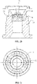
FIG. 1 is a schematic diagram of a structure of a motor in a conventional technology; -
FIG. 2a is a schematic diagram of a structure of a motor according to an embodiment of this application; -
FIG. 2b is a schematic diagram of a structure of a motor whose load bearing, housing, and end cover are not illustrated according to an embodiment of this application; -
FIG. 2c is a schematic diagram of a structure of a conductive bearing in a motor according to an embodiment of this application; -
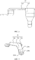
FIG. 3 is a schematic diagram of a structure of a conductive sheet in a motor according to an embodiment of this application; -
FIG. 4 is a schematic diagram of another structure of a conductive sheet in a motor according to an embodiment of this application; -
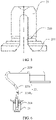
FIG. 5 is a schematic diagram of a structure of a conductive pillar in a motor according to an embodiment of this application; -
FIG. 6 is a schematic diagram of a structure in which a conductive pillar and a conductive sheet in a motor fit with each other according to an embodiment of this application; -
FIG. 7 is a schematic diagram of another structure of a motor whose load bearing, housing, and end cover are not illustrated according to an embodiment of this application; -
FIG. 8 is a schematic diagram of another structure of a conductive sheet in a motor according to an embodiment of this application; -
FIG. 9 is a schematic diagram of another structure of a conductive sheet in a motor according to an embodiment of this application; -
FIG. 10 is a schematic diagram of another structure of a conductive pillar in a motor according to an embodiment of this application; and -
FIG. 11 is a schematic diagram of another structure in which a conductive pillar and a conductive sheet in a motor fit with each other according to an embodiment of this application. - 1: housing; 2: output shaft; 3: bearing; 10: conductive bearing; 11: outer ring; 12: inner ring; 20: conductive component; 21: conductive pillar; 210: groove; 211: pedestal; 212: opening; 213: mounting base; 22: conductive sheet; 220: first connection sheet; 2201: arch-shaped part; 2202: first connection part; 2203: first mounting hole; 221: second connection sheet; 2210: insertion part; 2211: second connection part; 222: connection arm; 2220: second mounting hole; 2221: through hole; 30: load bearing; 40: output shaft; 41: positioning hole; 50: blocking member; 60: housing; 70: end cover; 80: nut.
- To make objectives, technical solutions, and advantages of this application clearer, the following further describes this application in detail with reference to accompanying drawings.
- A conventional internal combustion engine is usually used as a power source in a conventional fuel vehicle. With continuous innovation of technologies and continuous development of battery technologies, an electric vehicle that uses a motor as a power source is gradually widely used. Referring to
FIG. 1 , the motor includes ahousing 1 and a rotor located in thehousing 1, and the rotor is usually positioned in thehousing 1 by using abearing 3. Running of the motor rotor needs to depend on electric energy of a battery. Therefore, charges are inevitably accumulated in the rotor in the motor. When the charges pass through thebearing 3 configured to support anoutput shaft 2, an undesirable phenomenon such as electrical corrosion easily occurs in thebearing 3, and consequently a service life of thebearing 3 is shortened. - Therefore, the embodiments of this application provide a motor, to release a common-mode voltage at an output shaft by using a conductive bearing and a conductive component, so as to prevent a load bearing from being electrically corroded.
- To make the objectives, technical solutions, and advantages of this application clearer, with reference to accompanying drawings and specific embodiments, the following further describes in detail the motor provided in this application.
- Terms used in the following embodiments are merely intended to describe specific embodiments, but are not intended to limit this application. The terms "one", "a" and "this" of singular forms used in this specification and the appended claims of this application are also intended to include plural forms, unless otherwise specified in the context clearly.
- Reference to "an embodiment", "some embodiments", or the like described in this specification indicates that one or more embodiments of this application include a specific feature, structure, or characteristic described with reference to the embodiments. Therefore, in this specification, statements, such as "in an embodiment", "in some embodiments", "in some other embodiments", and "in other embodiments", that appear at different places do not necessarily mean referring to a same embodiment, instead, they mean "one or more but not all of the embodiments", unless otherwise specifically emphasized. The terms "include", "comprise", "have", and their variants all mean "include but are not limited to", unless otherwise specifically emphasized.
- In an embodiment of the motor provided in this application, referring to
FIG. 2a ,FIG. 2b, and FIG. 2c , the motor includes aconductive bearing 10, aconductive component 20, ahousing 60, and anoutput shaft 40. Theoutput shaft 40 is disposed in thehousing 60. Apositioning hole 41 is disposed on an end face of a first end of theoutput shaft 40, and thepositioning hole 41 is disposed coaxially with theoutput shaft 40. Theconductive bearing 10 is disposed in thepositioning hole 41, theconductive bearing 10 includes aninner ring 12 and an outer ring 11 (for details, refer toFIG. 2c ), and theouter ring 11 of theconductive bearing 10 is fixedly connected to theoutput shaft 40. One end of theconductive component 20 is fixedly connected to theinner ring 12 of theconductive bearing 10, and the other end is connected to thehousing 60. During rotation of theoutput shaft 40 of the motor, because theconductive component 20 is connected to theinner ring 12 of theconductive bearing 10, when theoutput shaft 40 drives theouter ring 11 of theconductive bearing 10 to rotate, theinner ring 12 of theconductive bearing 10 does not rotate with rotation of theouter ring 11 of theconductive bearing 10. Therefore, theconductive component 20 in the motor remains still relative to theoutput shaft 40, and it is ensured that theoutput shaft 40, theconductive bearing 10, and theconductive component 20 remain connected to each other. In this way, when a common-mode voltage generated during running of a motor rotor in the motor passes through theoutput shaft 40, accumulated charges may be transferred from theconductive bearing 10 to theconductive component 20, and then transferred from theconductive component 20 to ground. Therefore, a bearing configured to support theoutput shaft 40 can be prevented from being electrically corroded by the charges accumulated due to the common-mode voltage, to prolong a service life of the bearing configured to support theoutput shaft 40. - It should be noted that the
output shaft 40 may be positioned in thehousing 60 by using aload bearing 30, and a resistance of the load bearing 30 is greater than a total sum of resistances of theconductive bearing 10 and theconductive component 20. Therefore, the charges accumulated in a running process of the motor are output by using theconductive bearing 10 and theconductive component 20 that have a smaller sum of resistances, to prevent the load bearing 30 from being electrically corroded. - In a specific solution, the
conductive component 20 may include aconductive pillar 21 and aconductive sheet 22. Theconductive pillar 21 may be an integral structure, or one end of theconductive pillar 21 is connected to theinner ring 12 of theconductive bearing 10, the other end of theconductive pillar 21 is connected to theconductive sheet 22, and theconductive sheet 22 is connected to thehousing 60. When the motor works, theoutput shaft 40 may drive theouter ring 11, that is of theconductive bearing 10 and that fits with theoutput shaft 40, to rotate, and theinner ring 12 of theconductive bearing 10 is still relative to theouter ring 11 of theconductive bearing 10. Therefore, theconductive pillar 21 and theconductive sheet 22 connected to theconductive pillar 21 do not rotate with rotation of theouter ring 11 of theconductive bearing 10, and mounting stability of theconductive pillar 21 and theconductive sheet 22 is ensured. In this way, when the common-mode voltage generated during running of the motor rotor passes through theoutput shaft 40, the accumulated charges may be transferred from theconductive bearing 10 to theconductive pillar 21, and then transferred from theconductive sheet 22 to thehousing 60 for grounding, to implement charge output, and prevent the load bearing 30 from being electrically corroded. - It should be noted that, in a specific assembling process, first, the
conductive bearing 10 may be mounted in thepositioning hole 41 on theoutput shaft 40. When theconductive bearing 10 fits with thepositioning hole 41 on theoutput shaft 40, an outer diameter of theouter ring 11 of theconductive bearing 10 may be greater than an inner diameter of thepositioning hole 41 on theoutput shaft 40. Therefore, interference fitting is implemented between theconductive bearing 10 and thepositioning hole 41 on theoutput shaft 40, to prevent sliding friction from occurring between theconductive bearing 10 and theoutput shaft 40 due to slipping, and improve stability of a connection between theconductive bearing 10 and theoutput shaft 40. Alternatively, when theconductive bearing 10 fits with thepositioning hole 41 on theoutput shaft 40, theouter ring 11 of theconductive bearing 10 may fit with thepositioning hole 41 on theoutput shaft 40 through interference. In addition, when theconductive pillar 21 fits with theinner ring 12 of theconductive bearing 10, an outer diameter of a part of theconductive pillar 21 that fits with theinner ring 12 of theconductive bearing 10 is greater than an inner diameter of theinner ring 12 of theconductive bearing 10, and the part ofconductive pillar 21 fits with theinner ring 12 of theconductive bearing 10 through interference. Therefore, theconductive pillar 21 can always be in contact with theconductive bearing 10, to ensure that the charges can be transferred from theconductive bearing 10 to theconductive pillar 21. Theconductive pillar 21 and thehousing 60 may be connected to each other by using theconductive sheet 22, so that a current between theoutput shaft 40 and thehousing 60 is conducted, to eliminate the common-mode voltage generated at theoutput shaft 40. Theconductive sheet 22 is connected to an outer side of thehousing 60. After theconductive sheet 22 is connected to thehousing 60, anend cover 70 of the motor is mounted on the outer side of thehousing 60 to cover theconductive sheet 22. This manner can improve mounting convenience and avoid blind assembling. - In the foregoing solution, referring to
FIG. 3 , theconductive sheet 22 may have a plurality of forms. For example, theconductive sheet 22 may include onefirst connection sheet 220 and onesecond connection sheet 221. One end of thesecond connection sheet 221 is connected to theconductive pillar 21, the other end of thesecond connection sheet 221 is connected to thefirst connection sheet 220, and thefirst connection sheet 220 can be connected to thehousing 60. In this case, the charges accumulated in the running process of the motor may flow to thehousing 60 in a direction from the output shaft to theconductive bearing 10, theconductive pillar 21, thesecond connection sheet 221, and thefirst connection sheet 220, to eliminate the common-mode voltage generated in the running process of the motor. - To improve stability of a connection between the
conductive sheet 22 and thehousing 60, referring toFIG. 4 , theconductive sheet 22 may alternatively include twofirst connection sheets 220. When there are twofirst connection sheets 220, the twofirst connection sheets 220 are connected to each other, and both of the twofirst connection sheets 220 may be connected to thehousing 60. Thesecond connection sheet 221 may be connected to a part at which the twofirst connection sheets 220 are connected, and an end of thesecond connection sheet 221 that is away from the twofirst connection sheets 220 extends to a position of theconductive pillar 21, and remains electrically connected to theconductive pillar 21. The twofirst connection sheets 220 may be disposed at an angle, so that the twofirst connection sheets 220 and thehousing 60 are disposed in a triangle, to improve stability of the connection between theconductive sheet 22 and thehousing 60. In this case, the charges accumulated in the running process of the motor may flow from theoutput shaft 40 to theconductive bearing 10, theconductive pillar 21, and thesecond connection sheet 221, and then flow from the twofirst connection sheets 220 to thehousing 60, to eliminate the common-mode voltage generated in the running process of the motor. In this way, when onefirst connection sheet 220 in the twofirst connection sheets 220 is broken or disconnected from thehousing 60, the otherfirst connection sheet 220 can still keep theconductive pillar 21 and thehousing 60 connected to each other. This can prolong a service life of the motor and can reduce maintenance costs. - It should be noted that, when the
conductive sheet 22 is specifically disposed, there may be three or morefirst connection sheets 220. A larger quantity offirst connection sheets 220 indicates higher stability of the connection between theconductive sheet 22 and thehousing 60. A specific quantity offirst connection sheets 220 for use needs to be adjusted based on specific space inside thehousing 60 and a use status. Still referring toFIG. 4 , when thefirst connection sheet 220 is specifically disposed, thefirst connection sheet 220 may include an arch-shapedpart 2201 and afirst connection part 2202. Thefirst connection part 2202 may be connected to thehousing 60 in a manner of welding, a bolt, elastic connection, or abutting. When thefirst connection part 2202 is connected to thehousing 60 by using a bolt, at least onefirst mounting hole 2203 may be disposed on thefirst connection part 2202, and the bolt passes through thefirst mounting hole 2203 to fasten thefirst connection part 2202 to thehousing 60. One end of the arch-shapedpart 2201 is connected to thefirst connection part 2202, and the other end of the arch-shapedpart 2201 is connected to thesecond connection sheet 221. With disposition of the arch-shapedpart 2201, when theconductive sheet 22 is mounted on thehousing 60, theconductive sheet 22 can be adapted to thehousing 60 with different shapes. In addition, with disposition of the arch-shapedpart 2201, large deformation can also be generated when thefirst connection sheet 220 is connected to thehousing 60. - There may be a plurality of manners of connecting the
first connection sheet 220 and thesecond connection sheet 221. For example, thefirst connection sheet 220 and thesecond connection sheet 221 may be integrally disposed, or thefirst connection sheet 220 and thesecond connection sheet 221 may be connected by using a bolt and a nut. In other words, a first connection hole that fits with thesecond connection sheet 221 is further disposed on thefirst connection sheet 220, a second connection hole that fits with thefirst connection sheet 220 is disposed on thesecond connection sheet 221, and the bolt passes through the second connection hole and the first connection hole to connect thesecond connection sheet 221 and thefirst connection sheet 220. - In the foregoing solution, referring to
FIG. 4 andFIG. 5 , to conveniently connect theconductive pillar 21 to thesecond connection sheet 221, agroove 210 may be disposed on theconductive pillar 21. Thegroove 210 may be facing a side of thefirst connection sheet 220. In addition, on a side of thegroove 210 that faces thefirst connection sheet 220, apedestal 211 is further disposed on theconductive pillar 21. Therefore, when theconductive pillar 21 fits with theconductive bearing 10 through interference, thepedestal 211 can abut on a side of theconductive bearing 10 that faces thefirst connection sheet 220, to improve stability of fitting between theconductive pillar 21 and theconductive bearing 10. To enable thesecond connection sheet 221 to be conveniently inserted into thegroove 210 on theconductive pillar 21, referring toFIG. 6 , thesecond connection sheet 221 may include aninsertion part 2210 inserted into thegroove 210 and asecond connection part 2211 connected to theinsertion part 2210. One end of thesecond connection part 2211 is connected to thefirst connection sheet 220, and the other end of thesecond connection part 2211 is connected to theinsertion part 2210. When theconductive sheet 22 is specifically mounted on thehousing 60 and is inserted into the other end of theconductive pillar 21, theinsertion part 2210 and thesecond connection part 2211 may be disposed at an angle. Therefore, theinsertion part 2210 can be quickly inserted into thegroove 210, and theinsertion part 2210 can remain being in contact with an inner wall of thegroove 210. This ensures that theconductive pillar 21 can transfer the charges to theinsertion part 2210, so that the charges are transferred from thesecond connection part 2211 to thefirst connection sheet 220. With disposition of thegroove 210 on theconductive pillar 21, impacts such as an assembling error and a position error of theconductive sheet 22 can be further reduced, to improve conductive reliability and reduce manufacturing costs. In addition, disposition of thegroove 210 can further implement buffering and vibration absorption functions. - It should be noted that, when a strength condition of the
conductive pillar 21 is met, a plurality ofgrooves 210 may be disposed (not shown inFIG. 6 ), and the plurality ofgrooves 210 are distributed at intervals, so that theinsertion part 2210 can fit with theconductive pillar 21 more quickly. Thegroove 210 may penetrate through theconductive pillar 21 in a radial direction of theconductive pillar 21, and a part of thegroove 210 may extend to a position at which theconductive pillar 21 fits with theinner ring 12 of theconductive bearing 10. In this case, when theconductive pillar 21 fits with theinner ring 12 of theconductive bearing 10, theconductive pillar 21 located on two sides of thegroove 210 may be deformed towards a center of theconductive pillar 21. Therefore, when theconductive pillar 21 fits with theinner ring 12 of theconductive bearing 10 through interference, interference force exerted on theinner ring 12 of theconductive bearing 10 is reduced, and theconductive bearing 10 is prevented from being damaged. In addition, thegroove 210 may be in a cavity form, and an opening of thegroove 210 faces a side of thesecond connection sheet 221, so that thesecond connection sheet 221 can be clamped in thegroove 210. - In a possible implementation solution, the
conductive sheet 22 may be further connected to theconductive pillar 21 in the following manner: A through hole that fits with theconductive pillar 21 is directly disposed on theconductive sheet 22, a thread is disposed on an outer surface of an end of theconductive pillar 21 that is away from theconductive bearing 10, a mounting base is fixedly disposed at a position near the thread, and the mounting base may abut on theconductive sheet 22. In a specific assembling process, a part of theconductive pillar 21 that is provided with the thread passes through the through hole, and a nut is connected to the threaded part of the conductive pillar and abuts on theconductive sheet 22 to press theconductive sheet 22 against a position of the mounting base, so that theconductive sheet 22 remains electrically connected to theconductive pillar 21. Alternatively, referring toFIG. 7 , a through hole that fits with theconductive pillar 21 is disposed on theconductive sheet 22. An end of theconductive pillar 21 that is away from theconductive bearing 10 may pass through the through hole, a part of theconductive pillar 21 that passes through the through hole fits with anut 80 through interference, and thenut 80 is in contact with theconductive sheet 22, so that theconductive pillar 21 remains electrically connected to theconductive sheet 22. In this case, the charges accumulated in the running process of the motor may flow to thehousing 60 in a direction from theoutput shaft 40 to theconductive bearing 10, theconductive pillar 21, and theconductive sheet 22, to eliminate the common-mode voltage generated in the running process of the motor. - In the foregoing solution, referring to
FIG. 8 , theconductive sheet 22 may specifically include at least oneconnection arm 222. A throughhole 2221 that fits with theconductive pillar 21 is disposed on one end of theconnection arm 222, and asecond mounting hole 2220 configured to be connected to thehousing 60 is disposed on the other end of theconnection arm 222. A bolt passes through thesecond mounting hole 2220 to connect theconnection arm 222 to thehousing 60. During specific disposition, there may be a plurality of second mountingholes 2220, so that theconnection arm 222 is mounted on thehousing 60. In addition, a plurality of throughholes 2221 may be disposed, so that theconductive pillar 21 is connected to theconnection arm 222. - When the
conductive sheet 22 is specifically disposed, referring toFIG. 9 , theconductive sheet 22 may alternatively include twoconnection arms 222. A projection of the twoconnection arms 222 on a horizontal plane may be a rectangle, or may be a V-shape (not shown inFIG. 9 ). A throughhole 2221 may be disposed at a position of a part at which the twoconnection arms 222 are connected, or may be disposed on oneconnection arm 222 in the twoconnection arms 222, or a throughhole 2221 is disposed on each of the twoconnection arms 222. Asecond mounting hole 2220 may be disposed on each of the twoconnection arms 222, and thesecond mounting hole 2220 may be disposed at an end part of theconnection arm 222. Two bolts and the two second mountingholes 2220 connect the twoconnection arms 222 to thehousing 60, so that theconductive sheet 22 can be more stably connected to thehousing 60. - Specifically, the conductive sheet may alternatively include three, four, or more connection arms 222 (not shown in
FIG. 9 ). When there are threeconnection arms 222, the threeconnection arms 222 may be disposed in a Y-shape or a T-shape. A throughhole 2221 may be disposed at a position of a part at which the threeconnection arms 222 are connected, or a throughhole 2221 may be disposed on each of the threeconnection arms 222, or may be disposed on any one of the threeconnection arms 222. In this way, a position precision requirement on theconductive pillar 21 may be reduced. Asecond mounting hole 2220 may also be disposed on each of the threeconnection arms 222, and bolts may pass through the second mountingholes 2220 to fasten the three connection arms to thehousing 60. - In addition, when the
conductive sheet 22 includes at least twoconnection arms 222, the at least twoconnection arms 222 may be integrally disposed, or may be separately disposed. When a separate structure is used for the at least twoconnection arms 222, the at least twoconnection arms 222 may be connected by using a bolt. Specifically, at a position at which the at least twoconnection arms 222 are connected to each other, a through hole is disposed on each connection arm, theconductive pillar 21 passes through the two through holes on the twoconnection arms 222, and then the twoconnection arms 222 are fastened to theconductive pillar 21 by using a nut. - In the foregoing solution, referring to
FIG. 10 and FIG. 11 , when theconductive pillar 21 is specifically disposed, anopening 212 is disposed on a side of theconductive pillar 21 that faces the conductive bearing, and a mountingbase 213 is further disposed on theconductive pillar 21. Theopening 212 extends to an end of theconductive pillar 21 that is provided with the mountingbase 213. A part of theconductive pillar 21 that is located at the mountingbase 213 and that is away from the opening may also be cylindrical. One nut fits with a part of theconductive pillar 21 that is away from theopening 212 and that passes through the through hole on theconductive sheet 22 through interference, so that theconductive pillar 21 can be connected to theconductive sheet 22. With disposition of theopening 212, when theconductive pillar 21 fits with the conductive bearing through interference, extrusion force exerted on the inner ring of the conductive bearing can be reduced, to ensure that theconductive pillar 21 can be in contact with the inner ring of the conductive bearing, and further reduce a strength requirement on the conductive bearing. There may be a plurality ofopenings 212, extension directions of the plurality ofopenings 212 are the same, and depths (lengths by which the openings extend to the end of theconductive pillar 21 that is provided with the mounting base 213) of the plurality ofopenings 212 may be different or the same. - In a possible implementation solution, when the
conductive pillar 21 is specifically disposed, an outer surface of theconductive pillar 21 may be disposed as a smooth surface, so that theconductive pillar 21 is inserted into theinner ring 12 of theconductive bearing 10 to fit with theconductive bearing 10. Alternatively, an outer surface of theconductive pillar 21 may be disposed as a knurl surface (not shown inFIG. 10 and FIG. 11 ). Therefore, after theconductive pillar 21 fits with theinner ring 12 of theconductive bearing 10, friction between theconductive pillar 21 and theinner ring 12 of theconductive bearing 10 increases, to reduce a probability of relative rotation between theconductive pillar 21 and theinner ring 12 of theconductive bearing 10. Alternatively, an outer surface of theconductive pillar 21 may be disposed in a drum shape (not shown inFIG. 10 and FIG. 11 ). In this case, when theconductive pillar 21 fits with theinner ring 12 of theconductive bearing 10, a drum-shaped part of theconductive pillar 21 may be adapted to theinner ring 12 of theconductive bearing 10, so that interference fitting is implemented between theconductive pillar 21 and theconductive bearing 10. In addition, the outer surface of theconductive pillar 21 may be in a plurality of forms, provided that theconductive pillar 21 can remain being in contact with theinner ring 12 of theconductive bearing 10. The forms are not enumerated herein. - In the foregoing solution, the
conductive sheet 22 may be specifically disposed as an elastic sheet. Therefore, when theconductive sheet 22 is connected to thehousing 60 and theconductive pillar 21, theconductive sheet 22 can occupy small space in thehousing 60, to connect theconductive pillar 21 to thehousing 60. In addition, disposing theconductive sheet 22 as an elastic sheet may reduce a difficulty of mounting theoutput shaft 40 on the motor and improve assembling convenience. - In the foregoing solution, the positioning hole may be a blind hole or a through hole. When the positioning hole is a through hole, still referring to
FIG. 2a , in an actual working process of the motor, theoutput shaft 40 and another transmission component need to be lubricated by using lubricating oil. To prevent the lubricating oil from flowing from the positioning hole on theoutput shaft 40 to theconductive bearing 10, a blockingmember 50 may be further disposed in the positioning hole on theoutput shaft 40. The blockingmember 50 is configured to block the lubricating oil inside theoutput shaft 40, to ensure that the lubricating oil does not flow to theconductive bearing 10. In addition, the blockingmember 50 rotates with rotation of theoutput shaft 40. Therefore, when the blockingmember 50 is specifically disposed, the blockingmember 50 and theconductive bearing 10 may be spaced apart, to prevent the blockingmember 10 from driving theinner ring 12 of theconductive bearing 10 to rotate to drive theconductive pillar 21 that fits with theinner ring 12 of theconductive bearing 10 through interference and theconductive sheet 22 connected to theconductive pillar 21 to rotate. - It should be noted that the
conductive pillar 21 fits with theinner ring 12 of theconductive bearing 10 through interference, and theconductive pillar 21 may extend to an end of the blockingmember 50 by a distance. Therefore, an interval between the blockingmember 50 and theconductive bearing 10 also needs to be greater than the distance by which theconductive pillar 21 extends, to prevent the blockingmember 50 from being in contact with theconductive pillar 21 to drive theconductive pillar 21 to rotate. - Based on a specific structure of the motor described above, this application further provides a powertrain, including a transmission mechanism and the motor in the foregoing technical solution. The transmission mechanism is connected to the output shaft included in the motor described above. When a common-mode voltage generated in a running process of the motor passes through the output shaft, accumulated charges may be transferred from the
conductive bearing 10 and theconductive component 20 to ground, to output the accumulated charges. Therefore, a bearing configured to support theoutput shaft 40 is prevented from being electrically corroded, and a service life of the bearing is prolonged. - Based on a specific structure of the motor described above, this application further provides a vehicle, including the motor in the foregoing solution. The vehicle that uses the motor runs more stably.
- The foregoing descriptions are merely specific implementations of this application, but are not intended to limit the protection scope of this application. Any variation or replacement readily figured out by a person skilled in the art within the technical scope disclosed in this application shall fall within the protection scope of this application. Therefore, the protection scope of this application shall be subject to the protection scope of the claims.
Claims (18)
- A motor, comprising a housing, an output shaft, a conductive bearing, and a conductive component, whereinthe output shaft is positioned in the housing;a positioning hole is disposed on an end face of a first end of the output shaft, and the positioning hole is disposed coaxially with the output shaft;the conductive bearing is disposed in the positioning hole, the conductive bearing comprises an inner ring and an outer ring, and the outer ring of the conductive bearing is fixedly connected to the output shaft; andone end of the conductive component is fixedly connected to the inner ring of the conductive bearing, and the other end is connected to the housing.
- The motor according to claim 1, wherein the output shaft is positioned in the housing by using a load bearing, and a resistance of the load bearing is greater than a total sum of resistances of the conductive bearing and the conductive component.
- The motor according to claim 1 or 2, wherein the conductive component comprises a conductive pillar and a conductive sheet, one end of the conductive pillar is fixedly connected to the inner ring of the conductive bearing, and the other end of the conductive pillar is fixedly connected to the housing by using the conductive sheet.
- The motor according to claim 3, wherein the conductive sheet comprises a first connection sheet and a second connection sheet, and the first connection sheet and the second connection sheet are an integral structure, or the first connection sheet and the second connection sheet are connected, wherein the first connection sheet is connected to the housing, and the second connection sheet is clamped to the other end of the conductive pillar.
- The motor according to claim 4, wherein a groove is disposed on the other end of the conductive pillar, and the second connection sheet is clamped in the groove.
- The motor according to claim 4 or 5, wherein the first connection sheet comprises an arch-shaped part and a first connection part, the first connection part is connected to one end of the arch-shaped part, a first mounting hole that fits with the housing is disposed on the first connection part, and the other end of the arch-shaped part is connected to the second connection sheet.
- The motor according to claim 4 or 5, wherein the second connection sheet comprises an insertion part inserted into the other end of the conductive pillar and a connection part that connects the insertion part to the first connection sheet.
- The motor according to any one of claims 4 to 7, wherein there are two first connection sheets, both of the two first connection sheets are connected to the housing, and the second connection sheet is connected to the two first connection sheets.
- The motor according to claim 8, wherein the two first connection sheets and the second connection sheet are an integral structure.
- The motor according to claim 3, wherein a through hole is disposed on the conductive sheet, and the conductive pillar passes through the through hole and is connected to the conductive sheet by using a nut.
- The motor according to claim 10, wherein an opening is disposed on an end of the conductive pillar that faces the conductive bearing, and the opening extends in a direction of the conductive sheet.
- The motor according to claim 10, wherein a second mounting hole is disposed on the conductive sheet, and the second mounting hole is configured to fit with the housing.
- The motor according to any one of claims 1 to 12, wherein the motor further comprises an end cover, the end cover is fastened to an end of the housing, and the conductive component is located between the end cover and the housing.
- The motor according to any one of claims 3 to 12, wherein the conductive sheet is an elastic sheet.
- The motor according to any one of claims 3 to 12, wherein the positioning hole is a through hole or a blind hole.
- The motor according to claim 15, wherein when the positioning hole is a through hole, the motor further comprises a blocking member, the blocking member is disposed in the through hole, and the blocking member is located on a side of the conductive bearing that faces away from the conductive sheet.
- A powertrain, comprising a transmission mechanism and the motor according to any one of claims 1 to 16, wherein the transmission mechanism is connected to the output shaft.
- A vehicle, comprising the motor according to any one of claims 1 to 16.
Applications Claiming Priority (1)
| Application Number | Priority Date | Filing Date | Title |
|---|---|---|---|
| CN202011444829.2A CN112572144B (en) | 2020-12-08 | 2020-12-08 | Motor, power assembly and vehicle |
Publications (2)
| Publication Number | Publication Date |
|---|---|
| EP4012902A1 true EP4012902A1 (en) | 2022-06-15 |
| EP4012902B1 EP4012902B1 (en) | 2023-01-18 |
Family
ID=75131128
Family Applications (1)
| Application Number | Title | Priority Date | Filing Date |
|---|---|---|---|
| EP21212975.3A Active EP4012902B1 (en) | 2020-12-08 | 2021-12-07 | Motor, powertrain, and vehicle |
Country Status (4)
| Country | Link |
|---|---|
| US (1) | US12113421B2 (en) |
| EP (1) | EP4012902B1 (en) |
| CN (1) | CN112572144B (en) |
| WO (1) | WO2022121807A1 (en) |
Families Citing this family (16)
| Publication number | Priority date | Publication date | Assignee | Title |
|---|---|---|---|---|
| CN112572144B (en) | 2020-12-08 | 2023-03-10 | 华为数字能源技术有限公司 | Motor, power assembly and vehicle |
| CN112701824B (en) * | 2020-12-25 | 2022-06-14 | 华为数字能源技术有限公司 | Motor rotor, motor and vehicle |
| CN112994363A (en) * | 2021-03-31 | 2021-06-18 | 华为技术有限公司 | Motor, power assembly and electric vehicle |
| CN114301241B (en) * | 2021-03-31 | 2024-06-11 | 华为数字能源技术有限公司 | Motors, powertrains and motor drive equipment |
| EP4199327A4 (en) * | 2021-07-01 | 2024-06-05 | Anhui Welling Auto Parts Co., Ltd. | Electric motor and vehicle |
| CN114301213B (en) * | 2021-08-24 | 2023-06-27 | 华为数字能源技术有限公司 | Motor with a motor housing |
| CN113746275A (en) * | 2021-08-31 | 2021-12-03 | 株洲齿轮有限责任公司 | Motor discharge structure and shaft current flow guiding effect detection method |
| CN113949222B (en) * | 2021-09-15 | 2022-06-17 | 浙江中车尚驰电气有限公司 | Variable frequency motor shaft current protective structure |
| CN116073561A (en) * | 2021-10-29 | 2023-05-05 | 株洲中车时代电气股份有限公司 | A shaft end structure and motor for preventing electric corrosion of bearing |
| CN114221481B (en) * | 2021-11-18 | 2023-05-23 | 威睿电动汽车技术(宁波)有限公司 | Motor and vehicle |
| DE102021213384A1 (en) | 2021-11-29 | 2023-06-01 | Zf Friedrichshafen Ag | Arrangement for grounding a shaft |
| DE102021213387A1 (en) | 2021-11-29 | 2023-06-01 | Zf Friedrichshafen Ag | Arrangement for grounding a shaft |
| US12374953B2 (en) * | 2022-06-14 | 2025-07-29 | Hyundai Mobis Co., Ltd. | Anti-erosion structure of motor including a ground structure |
| KR102748761B1 (en) * | 2022-07-15 | 2025-01-03 | 미쓰비시덴키 가부시키가이샤 | Galvano scanner and laser processing machine |
| CN116094261A (en) * | 2023-02-09 | 2023-05-09 | 浙江吉利控股集团有限公司 | Bearing electric corrosion inhibiting structure, motor and automobile |
| CN117411249A (en) * | 2023-10-26 | 2024-01-16 | 浙江大学先进电气装备创新中心 | An electric excitation motor that uses conductive bearings to avoid overcurrent damage |
Citations (4)
| Publication number | Priority date | Publication date | Assignee | Title |
|---|---|---|---|---|
| DE10162818A1 (en) * | 2001-12-14 | 2003-06-26 | M & W Zander Facility Eng Gmbh | Electronically commutated electric motor has rotor seated on rotor shaft rotatably mounted via roller bearings in earthed stator housing, and electrically connected to stator housing via electrically conducting device(s) |
| DE102012204795A1 (en) * | 2012-03-26 | 2013-09-26 | Schaeffler Technologies AG & Co. KG | Wheel hub motor with equipotential bonding |
| CN109194039A (en) * | 2018-09-30 | 2019-01-11 | 广州小鹏汽车科技有限公司 | A kind of motor shaft current eliminates structure and motor |
| CN211827004U (en) * | 2020-02-22 | 2020-10-30 | 深圳大学 | An electrical conduction structure between a machine tool spindle and a machine bed |
Family Cites Families (17)
| Publication number | Priority date | Publication date | Assignee | Title |
|---|---|---|---|---|
| JPS5981254U (en) * | 1982-11-24 | 1984-06-01 | 三菱電機株式会社 | Grounding device for preventing galvanic corrosion of rotating electrical machine bearings |
| US5914547A (en) * | 1997-11-21 | 1999-06-22 | Magnetek, Inc. | Auxiliary bearing assembly for reduction of unwanted shaft voltages in an electric motor |
| JP2001140911A (en) * | 1999-11-11 | 2001-05-22 | Tsurumi Mfg Co Ltd | Bearing device |
| CN202889117U (en) | 2012-07-20 | 2013-04-17 | 南车株洲电力机车研究所有限公司 | Shaft voltage inhibiting device for slip ring motor |
| JP6248280B2 (en) * | 2012-11-22 | 2017-12-20 | パナソニックIpマネジメント株式会社 | Electric motor and electric device equipped with the electric motor |
| CN103516143A (en) * | 2013-10-23 | 2014-01-15 | 中达电机股份有限公司 | Shaft current eliminating device |
| JP5910673B2 (en) | 2014-06-30 | 2016-04-27 | ダイキン工業株式会社 | Electric motor |
| CN104607729B (en) | 2014-12-09 | 2017-03-22 | 上海交通大学 | High-speed arc discharge, flushing and rotating main shaft device |
| KR102281681B1 (en) * | 2015-01-12 | 2021-07-27 | 주식회사 만도 | Reducer for vehicle |
| CN104821691B (en) | 2015-04-23 | 2017-06-30 | 广东威灵电机制造有限公司 | Anti- motor bearings electric corrosion structure and plastic-sealing brushless DC motor |
| JP2018194106A (en) * | 2017-05-18 | 2018-12-06 | 日本精工株式会社 | Hub unit bearing |
| CN208112344U (en) * | 2018-04-20 | 2018-11-16 | 浙江炬光汽车零部件有限公司 | Low height size fans motor |
| CN111795068A (en) | 2019-04-09 | 2020-10-20 | 湖南中车时代电动汽车股份有限公司 | Conductive bearing |
| CN211351908U (en) * | 2019-12-26 | 2020-08-25 | 株洲齿轮有限责任公司 | Motor discharge structure and motor |
| CN211791039U (en) | 2020-04-23 | 2020-10-27 | 山东孚日电机有限公司 | Insulating end cover of motor |
| CN211859879U (en) | 2020-05-09 | 2020-11-03 | 无锡法拉第电机有限公司 | Single bearing generator bearing anti-static corrosion device |
| CN112572144B (en) | 2020-12-08 | 2023-03-10 | 华为数字能源技术有限公司 | Motor, power assembly and vehicle |
-
2020
- 2020-12-08 CN CN202011444829.2A patent/CN112572144B/en active Active
-
2021
- 2021-12-02 US US17/457,390 patent/US12113421B2/en active Active
- 2021-12-03 WO PCT/CN2021/135489 patent/WO2022121807A1/en not_active Ceased
- 2021-12-07 EP EP21212975.3A patent/EP4012902B1/en active Active
Patent Citations (4)
| Publication number | Priority date | Publication date | Assignee | Title |
|---|---|---|---|---|
| DE10162818A1 (en) * | 2001-12-14 | 2003-06-26 | M & W Zander Facility Eng Gmbh | Electronically commutated electric motor has rotor seated on rotor shaft rotatably mounted via roller bearings in earthed stator housing, and electrically connected to stator housing via electrically conducting device(s) |
| DE102012204795A1 (en) * | 2012-03-26 | 2013-09-26 | Schaeffler Technologies AG & Co. KG | Wheel hub motor with equipotential bonding |
| CN109194039A (en) * | 2018-09-30 | 2019-01-11 | 广州小鹏汽车科技有限公司 | A kind of motor shaft current eliminates structure and motor |
| CN211827004U (en) * | 2020-02-22 | 2020-10-30 | 深圳大学 | An electrical conduction structure between a machine tool spindle and a machine bed |
Also Published As
| Publication number | Publication date |
|---|---|
| CN112572144B (en) | 2023-03-10 |
| WO2022121807A1 (en) | 2022-06-16 |
| US12113421B2 (en) | 2024-10-08 |
| US20220209616A1 (en) | 2022-06-30 |
| EP4012902B1 (en) | 2023-01-18 |
| CN112572144A (en) | 2021-03-30 |
Similar Documents
| Publication | Publication Date | Title |
|---|---|---|
| US12113421B2 (en) | Motor, powertrain, and vehicle | |
| EP4068580A2 (en) | Motor, powertrain and electric vehicle | |
| JP4306476B2 (en) | Automotive alternator | |
| CN115566838A (en) | Motors and Vehicles | |
| WO2023272945A1 (en) | Electric motor and vehicle | |
| KR101795395B1 (en) | Bearing unit for drive motor | |
| JP2026509643A (en) | Powertrain and method for assembling the powertrain | |
| US12516701B2 (en) | Externally mountable conductive assembly with circular base plate | |
| US12470113B2 (en) | Electrically conductive device with centering projections | |
| CN214688876U (en) | A wheel and movable equipment | |
| EP4249772B1 (en) | Electric drive power transmission system box assembly having stepped pin positioning and mounting method of electric drive power transmission system box assembly | |
| CN115720016A (en) | Motor and vehicle | |
| CN114876964A (en) | Seal assembly and rolling bearing | |
| CN220985430U (en) | Bearing baffle, motor rotor assembly and motor assembly | |
| CN223854799U (en) | Shaft grounding structure and electric drive system | |
| CN119872747B (en) | Battery pack dynamic management and self-cleaning switching system and battery pack dynamic management method | |
| CN223854686U (en) | A type of mounted bearing | |
| CN224049647U (en) | One-way clutch belt pulley for automobile | |
| CN222229330U (en) | Tensioning device and vehicle with same | |
| CN221058149U (en) | Conductive structures, shaft end components, motors and vehicles | |
| CN219727780U (en) | Suspension actuators and automobiles | |
| CN217682892U (en) | Generating set with stable work | |
| CN222950269U (en) | Driving shaft assembly and vehicle | |
| CN223549906U (en) | EGR valve actuator | |
| CN219159400U (en) | Weight-reducing electromagnetic clutch |
Legal Events
| Date | Code | Title | Description |
|---|---|---|---|
| PUAI | Public reference made under article 153(3) epc to a published international application that has entered the european phase |
Free format text: ORIGINAL CODE: 0009012 |
|
| STAA | Information on the status of an ep patent application or granted ep patent |
Free format text: STATUS: THE APPLICATION HAS BEEN PUBLISHED |
|
| AK | Designated contracting states |
Kind code of ref document: A1 Designated state(s): AL AT BE BG CH CY CZ DE DK EE ES FI FR GB GR HR HU IE IS IT LI LT LU LV MC MK MT NL NO PL PT RO RS SE SI SK SM TR |
|
| STAA | Information on the status of an ep patent application or granted ep patent |
Free format text: STATUS: REQUEST FOR EXAMINATION WAS MADE |
|
| 17P | Request for examination filed |
Effective date: 20220714 |
|
| RBV | Designated contracting states (corrected) |
Designated state(s): AL AT BE BG CH CY CZ DE DK EE ES FI FR GB GR HR HU IE IS IT LI LT LU LV MC MK MT NL NO PL PT RO RS SE SI SK SM TR |
|
| GRAP | Despatch of communication of intention to grant a patent |
Free format text: ORIGINAL CODE: EPIDOSNIGR1 |
|
| STAA | Information on the status of an ep patent application or granted ep patent |
Free format text: STATUS: GRANT OF PATENT IS INTENDED |
|
| RIC1 | Information provided on ipc code assigned before grant |
Ipc: H02K 7/00 20060101ALI20220817BHEP Ipc: H02K 5/173 20060101ALI20220817BHEP Ipc: H02K 11/40 20160101AFI20220817BHEP |
|
| INTG | Intention to grant announced |
Effective date: 20220913 |
|
| GRAS | Grant fee paid |
Free format text: ORIGINAL CODE: EPIDOSNIGR3 |
|
| GRAA | (expected) grant |
Free format text: ORIGINAL CODE: 0009210 |
|
| STAA | Information on the status of an ep patent application or granted ep patent |
Free format text: STATUS: THE PATENT HAS BEEN GRANTED |
|
| AK | Designated contracting states |
Kind code of ref document: B1 Designated state(s): AL AT BE BG CH CY CZ DE DK EE ES FI FR GB GR HR HU IE IS IT LI LT LU LV MC MK MT NL NO PL PT RO RS SE SI SK SM TR |
|
| REG | Reference to a national code |
Ref country code: GB Ref legal event code: FG4D |
|
| REG | Reference to a national code |
Ref country code: DE Ref legal event code: R096 Ref document number: 602021001272 Country of ref document: DE |
|
| REG | Reference to a national code |
Ref country code: CH Ref legal event code: EP |
|
| REG | Reference to a national code |
Ref country code: AT Ref legal event code: REF Ref document number: 1545216 Country of ref document: AT Kind code of ref document: T Effective date: 20230215 Ref country code: IE Ref legal event code: FG4D |
|
| REG | Reference to a national code |
Ref country code: LT Ref legal event code: MG9D |
|
| REG | Reference to a national code |
Ref country code: NL Ref legal event code: MP Effective date: 20230118 |
|
| REG | Reference to a national code |
Ref country code: AT Ref legal event code: MK05 Ref document number: 1545216 Country of ref document: AT Kind code of ref document: T Effective date: 20230118 |
|
| P01 | Opt-out of the competence of the unified patent court (upc) registered |
Effective date: 20230524 |
|
| PG25 | Lapsed in a contracting state [announced via postgrant information from national office to epo] |
Ref country code: NL Free format text: LAPSE BECAUSE OF FAILURE TO SUBMIT A TRANSLATION OF THE DESCRIPTION OR TO PAY THE FEE WITHIN THE PRESCRIBED TIME-LIMIT Effective date: 20230118 |
|
| PG25 | Lapsed in a contracting state [announced via postgrant information from national office to epo] |
Ref country code: RS Free format text: LAPSE BECAUSE OF FAILURE TO SUBMIT A TRANSLATION OF THE DESCRIPTION OR TO PAY THE FEE WITHIN THE PRESCRIBED TIME-LIMIT Effective date: 20230118 Ref country code: PT Free format text: LAPSE BECAUSE OF FAILURE TO SUBMIT A TRANSLATION OF THE DESCRIPTION OR TO PAY THE FEE WITHIN THE PRESCRIBED TIME-LIMIT Effective date: 20230518 Ref country code: NO Free format text: LAPSE BECAUSE OF FAILURE TO SUBMIT A TRANSLATION OF THE DESCRIPTION OR TO PAY THE FEE WITHIN THE PRESCRIBED TIME-LIMIT Effective date: 20230418 Ref country code: LV Free format text: LAPSE BECAUSE OF FAILURE TO SUBMIT A TRANSLATION OF THE DESCRIPTION OR TO PAY THE FEE WITHIN THE PRESCRIBED TIME-LIMIT Effective date: 20230118 Ref country code: LT Free format text: LAPSE BECAUSE OF FAILURE TO SUBMIT A TRANSLATION OF THE DESCRIPTION OR TO PAY THE FEE WITHIN THE PRESCRIBED TIME-LIMIT Effective date: 20230118 Ref country code: HR Free format text: LAPSE BECAUSE OF FAILURE TO SUBMIT A TRANSLATION OF THE DESCRIPTION OR TO PAY THE FEE WITHIN THE PRESCRIBED TIME-LIMIT Effective date: 20230118 Ref country code: ES Free format text: LAPSE BECAUSE OF FAILURE TO SUBMIT A TRANSLATION OF THE DESCRIPTION OR TO PAY THE FEE WITHIN THE PRESCRIBED TIME-LIMIT Effective date: 20230118 Ref country code: AT Free format text: LAPSE BECAUSE OF FAILURE TO SUBMIT A TRANSLATION OF THE DESCRIPTION OR TO PAY THE FEE WITHIN THE PRESCRIBED TIME-LIMIT Effective date: 20230118 |
|
| PG25 | Lapsed in a contracting state [announced via postgrant information from national office to epo] |
Ref country code: SE Free format text: LAPSE BECAUSE OF FAILURE TO SUBMIT A TRANSLATION OF THE DESCRIPTION OR TO PAY THE FEE WITHIN THE PRESCRIBED TIME-LIMIT Effective date: 20230118 Ref country code: PL Free format text: LAPSE BECAUSE OF FAILURE TO SUBMIT A TRANSLATION OF THE DESCRIPTION OR TO PAY THE FEE WITHIN THE PRESCRIBED TIME-LIMIT Effective date: 20230118 Ref country code: IS Free format text: LAPSE BECAUSE OF FAILURE TO SUBMIT A TRANSLATION OF THE DESCRIPTION OR TO PAY THE FEE WITHIN THE PRESCRIBED TIME-LIMIT Effective date: 20230518 Ref country code: GR Free format text: LAPSE BECAUSE OF FAILURE TO SUBMIT A TRANSLATION OF THE DESCRIPTION OR TO PAY THE FEE WITHIN THE PRESCRIBED TIME-LIMIT Effective date: 20230419 Ref country code: FI Free format text: LAPSE BECAUSE OF FAILURE TO SUBMIT A TRANSLATION OF THE DESCRIPTION OR TO PAY THE FEE WITHIN THE PRESCRIBED TIME-LIMIT Effective date: 20230118 |
|
| REG | Reference to a national code |
Ref country code: DE Ref legal event code: R097 Ref document number: 602021001272 Country of ref document: DE |
|
| PG25 | Lapsed in a contracting state [announced via postgrant information from national office to epo] |
Ref country code: SM Free format text: LAPSE BECAUSE OF FAILURE TO SUBMIT A TRANSLATION OF THE DESCRIPTION OR TO PAY THE FEE WITHIN THE PRESCRIBED TIME-LIMIT Effective date: 20230118 Ref country code: RO Free format text: LAPSE BECAUSE OF FAILURE TO SUBMIT A TRANSLATION OF THE DESCRIPTION OR TO PAY THE FEE WITHIN THE PRESCRIBED TIME-LIMIT Effective date: 20230118 Ref country code: EE Free format text: LAPSE BECAUSE OF FAILURE TO SUBMIT A TRANSLATION OF THE DESCRIPTION OR TO PAY THE FEE WITHIN THE PRESCRIBED TIME-LIMIT Effective date: 20230118 Ref country code: DK Free format text: LAPSE BECAUSE OF FAILURE TO SUBMIT A TRANSLATION OF THE DESCRIPTION OR TO PAY THE FEE WITHIN THE PRESCRIBED TIME-LIMIT Effective date: 20230118 Ref country code: CZ Free format text: LAPSE BECAUSE OF FAILURE TO SUBMIT A TRANSLATION OF THE DESCRIPTION OR TO PAY THE FEE WITHIN THE PRESCRIBED TIME-LIMIT Effective date: 20230118 |
|
| PLBE | No opposition filed within time limit |
Free format text: ORIGINAL CODE: 0009261 |
|
| STAA | Information on the status of an ep patent application or granted ep patent |
Free format text: STATUS: NO OPPOSITION FILED WITHIN TIME LIMIT |
|
| PG25 | Lapsed in a contracting state [announced via postgrant information from national office to epo] |
Ref country code: SK Free format text: LAPSE BECAUSE OF FAILURE TO SUBMIT A TRANSLATION OF THE DESCRIPTION OR TO PAY THE FEE WITHIN THE PRESCRIBED TIME-LIMIT Effective date: 20230118 |
|
| 26N | No opposition filed |
Effective date: 20231019 |
|
| PG25 | Lapsed in a contracting state [announced via postgrant information from national office to epo] |
Ref country code: SI Free format text: LAPSE BECAUSE OF FAILURE TO SUBMIT A TRANSLATION OF THE DESCRIPTION OR TO PAY THE FEE WITHIN THE PRESCRIBED TIME-LIMIT Effective date: 20230118 |
|
| PG25 | Lapsed in a contracting state [announced via postgrant information from national office to epo] |
Ref country code: IT Free format text: LAPSE BECAUSE OF FAILURE TO SUBMIT A TRANSLATION OF THE DESCRIPTION OR TO PAY THE FEE WITHIN THE PRESCRIBED TIME-LIMIT Effective date: 20230118 |
|
| PG25 | Lapsed in a contracting state [announced via postgrant information from national office to epo] |
Ref country code: LU Free format text: LAPSE BECAUSE OF NON-PAYMENT OF DUE FEES Effective date: 20231207 |
|
| PG25 | Lapsed in a contracting state [announced via postgrant information from national office to epo] |
Ref country code: MC Free format text: LAPSE BECAUSE OF FAILURE TO SUBMIT A TRANSLATION OF THE DESCRIPTION OR TO PAY THE FEE WITHIN THE PRESCRIBED TIME-LIMIT Effective date: 20230118 |
|
| REG | Reference to a national code |
Ref country code: BE Ref legal event code: MM Effective date: 20231231 |
|
| PG25 | Lapsed in a contracting state [announced via postgrant information from national office to epo] |
Ref country code: MC Free format text: LAPSE BECAUSE OF FAILURE TO SUBMIT A TRANSLATION OF THE DESCRIPTION OR TO PAY THE FEE WITHIN THE PRESCRIBED TIME-LIMIT Effective date: 20230118 Ref country code: LU Free format text: LAPSE BECAUSE OF NON-PAYMENT OF DUE FEES Effective date: 20231207 |
|
| REG | Reference to a national code |
Ref country code: IE Ref legal event code: MM4A |
|
| PG25 | Lapsed in a contracting state [announced via postgrant information from national office to epo] |
Ref country code: IE Free format text: LAPSE BECAUSE OF NON-PAYMENT OF DUE FEES Effective date: 20231207 |
|
| PG25 | Lapsed in a contracting state [announced via postgrant information from national office to epo] |
Ref country code: BE Free format text: LAPSE BECAUSE OF NON-PAYMENT OF DUE FEES Effective date: 20231231 |
|
| PG25 | Lapsed in a contracting state [announced via postgrant information from national office to epo] |
Ref country code: FR Free format text: LAPSE BECAUSE OF NON-PAYMENT OF DUE FEES Effective date: 20231231 |
|
| PG25 | Lapsed in a contracting state [announced via postgrant information from national office to epo] |
Ref country code: IE Free format text: LAPSE BECAUSE OF NON-PAYMENT OF DUE FEES Effective date: 20231207 Ref country code: FR Free format text: LAPSE BECAUSE OF NON-PAYMENT OF DUE FEES Effective date: 20231231 Ref country code: BE Free format text: LAPSE BECAUSE OF NON-PAYMENT OF DUE FEES Effective date: 20231231 |
|
| PG25 | Lapsed in a contracting state [announced via postgrant information from national office to epo] |
Ref country code: BG Free format text: LAPSE BECAUSE OF FAILURE TO SUBMIT A TRANSLATION OF THE DESCRIPTION OR TO PAY THE FEE WITHIN THE PRESCRIBED TIME-LIMIT Effective date: 20230118 |
|
| PG25 | Lapsed in a contracting state [announced via postgrant information from national office to epo] |
Ref country code: BG Free format text: LAPSE BECAUSE OF FAILURE TO SUBMIT A TRANSLATION OF THE DESCRIPTION OR TO PAY THE FEE WITHIN THE PRESCRIBED TIME-LIMIT Effective date: 20230118 |
|
| PG25 | Lapsed in a contracting state [announced via postgrant information from national office to epo] |
Ref country code: CY Free format text: LAPSE BECAUSE OF FAILURE TO SUBMIT A TRANSLATION OF THE DESCRIPTION OR TO PAY THE FEE WITHIN THE PRESCRIBED TIME-LIMIT; INVALID AB INITIO Effective date: 20211207 |
|
| REG | Reference to a national code |
Ref country code: CH Ref legal event code: PL |
|
| PG25 | Lapsed in a contracting state [announced via postgrant information from national office to epo] |
Ref country code: CH Free format text: LAPSE BECAUSE OF NON-PAYMENT OF DUE FEES Effective date: 20241231 |
|
| PG25 | Lapsed in a contracting state [announced via postgrant information from national office to epo] |
Ref country code: TR Free format text: LAPSE BECAUSE OF FAILURE TO SUBMIT A TRANSLATION OF THE DESCRIPTION OR TO PAY THE FEE WITHIN THE PRESCRIBED TIME-LIMIT Effective date: 20230118 |
|
| PGFP | Annual fee paid to national office [announced via postgrant information from national office to epo] |
Ref country code: DE Payment date: 20251104 Year of fee payment: 5 |