EP4012876B1 - Inselbildungserkennungssystem und -verfahren - Google Patents
Inselbildungserkennungssystem und -verfahren Download PDFInfo
- Publication number
- EP4012876B1 EP4012876B1 EP21213363.1A EP21213363A EP4012876B1 EP 4012876 B1 EP4012876 B1 EP 4012876B1 EP 21213363 A EP21213363 A EP 21213363A EP 4012876 B1 EP4012876 B1 EP 4012876B1
- Authority
- EP
- European Patent Office
- Prior art keywords
- inverter
- islanding detection
- islanding
- detection
- mode
- Prior art date
- Legal status (The legal status is an assumption and is not a legal conclusion. Google has not performed a legal analysis and makes no representation as to the accuracy of the status listed.)
- Active
Links
Images


Classifications
-
- H—ELECTRICITY
- H02—GENERATION; CONVERSION OR DISTRIBUTION OF ELECTRIC POWER
- H02J—ELECTRIC POWER NETWORKS; CIRCUIT ARRANGEMENTS OR SYSTEMS FOR SUPPLYING OR DISTRIBUTING ELECTRIC POWER; SYSTEMS FOR STORING ELECTRIC ENERGY
- H02J3/00—Circuit arrangements for AC mains or AC distribution networks
- H02J3/38—Arrangements for feeding a single network from two or more generators or sources in parallel; Arrangements for feeding already energised networks from additional generators or sources in parallel
- H02J3/381—Dispersed generators
-
- H—ELECTRICITY
- H02—GENERATION; CONVERSION OR DISTRIBUTION OF ELECTRIC POWER
- H02J—ELECTRIC POWER NETWORKS; CIRCUIT ARRANGEMENTS OR SYSTEMS FOR SUPPLYING OR DISTRIBUTING ELECTRIC POWER; SYSTEMS FOR STORING ELECTRIC ENERGY
- H02J3/00—Circuit arrangements for AC mains or AC distribution networks
- H02J3/38—Arrangements for feeding a single network from two or more generators or sources in parallel; Arrangements for feeding already energised networks from additional generators or sources in parallel
- H02J3/388—Arrangements for the handling of islanding, e.g. for disconnection or for avoiding the disconnection of power
-
- G—PHYSICS
- G01—MEASURING; TESTING
- G01R—MEASURING ELECTRIC VARIABLES; MEASURING MAGNETIC VARIABLES
- G01R31/00—Arrangements for testing electric properties; Arrangements for locating electric faults; Arrangements for electrical testing characterised by what is being tested not provided for elsewhere
-
- G—PHYSICS
- G01—MEASURING; TESTING
- G01R—MEASURING ELECTRIC VARIABLES; MEASURING MAGNETIC VARIABLES
- G01R19/00—Arrangements for measuring currents or voltages or for indicating presence or sign thereof
-
- G—PHYSICS
- G01—MEASURING; TESTING
- G01R—MEASURING ELECTRIC VARIABLES; MEASURING MAGNETIC VARIABLES
- G01R19/00—Arrangements for measuring currents or voltages or for indicating presence or sign thereof
- G01R19/25—Arrangements for measuring currents or voltages or for indicating presence or sign thereof using digital measurement techniques
- G01R19/2513—Arrangements for monitoring electric power systems, e.g. power lines or loads; Logging
-
- H—ELECTRICITY
- H02—GENERATION; CONVERSION OR DISTRIBUTION OF ELECTRIC POWER
- H02J—ELECTRIC POWER NETWORKS; CIRCUIT ARRANGEMENTS OR SYSTEMS FOR SUPPLYING OR DISTRIBUTING ELECTRIC POWER; SYSTEMS FOR STORING ELECTRIC ENERGY
- H02J2101/00—Supply or distribution of decentralised, dispersed or local electric power generation
- H02J2101/20—Dispersed power generation using renewable energy sources
- H02J2101/22—Solar energy
- H02J2101/24—Photovoltaics
-
- H—ELECTRICITY
- H02—GENERATION; CONVERSION OR DISTRIBUTION OF ELECTRIC POWER
- H02J—ELECTRIC POWER NETWORKS; CIRCUIT ARRANGEMENTS OR SYSTEMS FOR SUPPLYING OR DISTRIBUTING ELECTRIC POWER; SYSTEMS FOR STORING ELECTRIC ENERGY
- H02J2103/00—Details of circuit arrangements for mains or AC distribution networks
- H02J2103/30—Simulating, planning, modelling, reliability check or computer assisted design [CAD] of electric power networks
-
- Y—GENERAL TAGGING OF NEW TECHNOLOGICAL DEVELOPMENTS; GENERAL TAGGING OF CROSS-SECTIONAL TECHNOLOGIES SPANNING OVER SEVERAL SECTIONS OF THE IPC; TECHNICAL SUBJECTS COVERED BY FORMER USPC CROSS-REFERENCE ART COLLECTIONS [XRACs] AND DIGESTS
- Y02—TECHNOLOGIES OR APPLICATIONS FOR MITIGATION OR ADAPTATION AGAINST CLIMATE CHANGE
- Y02E—REDUCTION OF GREENHOUSE GAS [GHG] EMISSIONS, RELATED TO ENERGY GENERATION, TRANSMISSION OR DISTRIBUTION
- Y02E10/00—Energy generation through renewable energy sources
- Y02E10/50—Photovoltaic [PV] energy
- Y02E10/56—Power conversion systems, e.g. maximum power point trackers
Definitions
- the application relates to islanding detection, and particularly to an islanding detection system and method for multiple inverters operating in parallel.
- inverter In a new energy power generation system, inverter is often used to convert DC electric energy into AC electric energy, and output of the inverter is connected to a load and a grid through a breaker.
- the inverter and the local load When the grid is disconnected due to a fault or other reasons, the inverter and the local load will operate in an islanding state. Since the islanding state will threaten overhaul and maintenance, it shall be detected and terminated in some conditions.
- detection of the islanding operation state comprises active islanding detection and passive islanding detection.
- the passive islanding detection is realized by monitoring parameters such as voltage and frequency at PCC point.
- the passive islanding detection since the passive islanding detection always has a large non-detection zone (NDZ), the active islanding detection shall be adopted as a supplement.
- the active islanding detection comprises active frequency shift, reactive injection, harmonic injection, and the like.
- a common processing measure is to adopt same islanding detection method and synchronous injection method. That is, in a system where multiple inverters are connected in parallel, the same active islanding detection method is adopted for all inverters.
- a master controller shall be designed in the system.
- the master controller can be a separate controller; or the master controller may be a controller of one inverter with controllers of other inverters as slave.
- the connection between the master controller and the slave controllers is established through communication.
- the master controller outputs a synchronous reference signal and transmits the synchronous reference signal to the respective slave controllers. After receiving the synchronous signal, the slave controllers execute the islanding detection action.
- a high-speed communication bus such as a CAN bus
- a high-speed communication bus such as a CAN bus
- the premise of the processing measure is that each inverter adopts the same islanding detection mode, and high-speed (or real-time) communication needs to be established between inverters to realize accurate synchronization. If one inverter in the system adopts different mode or the inverters in the system are not synchronized, islanding detection of the system may be failed, resulting in poor robustness of the algorithm.
- US2019/195923A1 discloses an islanding detection system according to the preamble of claim 1.
- one object of the application is to provide an islanding detection system for multiple inverters operating in parallel.
- a current detection circuit on a grid side or an AC side of the second inverter it can perform distributed or centralized islanding detection for different situations adaptively, thereby improving the pass rate of islanding detection.
- the application provides an islanding detection system for multiple inverters operating in parallel, the multiple inverters at least comprising a first inverter and a second inverter connected in parallel, wherein the islanding detection system comprises:
- the application further provides an islanding detection method for multiple inverters connected in parallel, the multiple inverters at least comprising a first inverter and a second inverter connected in parallel, wherein the islanding detection method comprises:
- an islanding detection system for multiple inverters operating in parallel comprises at least a first inverter 131 and a second inverter 170 connected in parallel.
- the islanding detection system further comprises a current detection circuit 140 (which is referred to as a first current detection circuit) and a controller 132.
- the first current detection circuit 140 may be arranged on a grid side or an AC side of the second inverter 170.
- the controller 132 is connected to the first current detection circuit 140 and the first inverter 131, and determines whether to perform a distributed islanding detection or a centralized islanding detection on the first inverter 131 and the second inverter 170 according to a grid voltage signal obtained by sampling a grid voltage and a current detection signal detected by the first current detection circuit 140.
- FIG. 1 illustrates a circuit diagram of an islanding detection system for multiple inverters operating in parallel according to one embodiment of the application.
- the system may comprise: a first DC source 110, a second DC source 120, an inverter system 130, a local load 190, a grid 150, a third DC source 160, a second inverter 170, a first current detection circuit 140 and a connector 180.
- the first DC source 110 for example, a photovoltaic panel
- the second DC source 120 for example, a household energy storage battery
- the inverter system 130 for example, is an energy storage inverter system.
- the third DC source 160 for example, an on-board battery, is connected to the second inverter 170.
- the second inverter 170 is an on-board charger, for example.
- the connector 180 may be a connector in form of a charging gun or the like.
- the system includes an electric vehicle, a photovoltaic panel, an energy storage battery, and an energy storage inverter.
- the first DC source 110 is the photovoltaic panel
- the second DC source 120 is the energy storage battery
- the third DC source is power battery installed in the electric vehicle
- the first inverter 131 is the energy storage inverter
- the second inverter 170 is a bi-directional charger installed in the electric vehicle
- the connector 180 is a charging gun integrated into the energy storage inverter.
- the energy storage inverter is designed with an energy management system that can perform state monitoring and power control on the energy storage battery and the power battery in the electric vehicle. It shall be noted that the respective DC sources and the inverters may also be applied to other technical fields, but the application is not limited thereto.
- the inverter system 130 may comprise a first inverter 131, a controller 132, a current detection circuit 133 (which is referred to as a second current detection circuit), and a breaker 134.
- the first inverter 131, the controller 132, the second current detection circuit 133, and the breaker 134 shown in FIG. 1 are discrete components, and in other embodiments, the controller 132, the second current detection circuit 133, and the breaker 134 may be integrated into the first inverter 131. It shall be noted that the inverter system 130 shall be provided with one second current detection circuit 133 in order to achieve control and islanding detection, which is arranged on an AC side of the first inverter 131.
- the second current detection circuit 133 is desired by the inverter system 130 itself and exists in current hardware, so explanations are omitted here.
- the first current detection circuit 140 shall be additionally provided in the system.
- the first current detection circuit 140 is arranged on an output side of the second inverter 170, for example, before and after the connector 180.
- the first current detection circuit 140 is arranged on a common output side of the first inverter 131 and the second inverter 170, i.e., a grid side.
- the second current detection circuit 133 and the first current detection circuit 140 may be current sensors CT, and a current detection signal sampled by the current sensors CT is inputted into the controller 132.
- the inverter system 130 comprises a voltage detection circuit (not shown) for sampling a grid voltage and inputting a grid voltage signal into the controller.
- the controller 132 completes recognition of islanding detection mode of the second inverter 170 and/or adjustment of islanding detection mode of the first inverter 131 itself through the processing of the sampled signals (e.g., the current detection signal and the grid voltage signal).
- the controller 132 is electrically connected to the first inverter 131 and transmits a control signal to the first inverter 131, thereby controlling the normal operational state of the first inverter 131, and realizing islanding detection and subsequent actions of the first inverter 131.
- the controller 132 controls the breaker 134 simultaneously, and after islanding is detected, the controller 132 controls the breaker 134 to disconnect the connection between the inverter system 130 and the load 190.
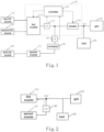
- FIG. 2 illustrates a simplified circuit diagram of an islanding detection system for multiple inverters operating in parallel in FIG. 1 of the application.
- the first current detection circuit 140 is arranged at an output of the second inverter 170.
- the first current detection circuit 140 may also be arranged on the grid side, with identical function and effect.
- FIG. 3 illustrates islanding detection mode based on reactive current injection according to one embodiment of the application.
- the functional mechanism of the islanding detection mode based on reactive current injection is as follows:
- the islanding detection mode includes but is not limited to the reactive current injection manner, and may also be other manners.
- the islanding detection when the multiple inverters operate in parallel is described by taking the reactive current injection as an example.
- FIG. 4 illustrates a flow diagram of an islanding detection method for multiple inverters operating in parallel according to one embodiment of the application. As shown in FIG. 4 , the method mainly comprises:
- the current detection signal sampled by the first current detection circuit 140 and the grid voltage signal sampled by a voltage detection circuit are inputted into the controller 132.
- the controller 132 fits the islanding detection mode of the second inverter 170 according to the current detection signal and the grid voltage signal. Specifically, the controller 132 may obtain electrical parameters including information of voltage, current, active power, reactive power, and frequency of the second inverter 170 according to the sampled signals.
- the controller 132 completes analysis and extraction of key features of the islanding detection mode of the second inverter 170, including disruption types (e.g., frequency shift, reactive injection, harmonic injection, etc.), disturbed period, disturbed amplitude, and the like, by obtaining mass electrical parameters of the second inverter 170.
- the controller 132 fits the islanding detection mode of the second inverter 170 according to the extracted features. Fitting of the islanding detection mode of the second inverter 170 may be based on mass sampled data (e.g., mass historical sampled data) including the current detection signal and the grid voltage signal sampled in the current period. As for fitting of the islanding detection mode of the second inverter 170, the fitting method in the prior art, or the method of machine learning may be adopted, but the application is not limited thereto.
- the controller 132 performs distributed islanding detection or centralized islanding detection accordingly according to judging whether the islanding detection mode is matched with one of the islanding detection modes library.
- the controller 132 is stored with a library including several typical islanding detection modes.
- the controller 132 compares the fitted islanding detection mode of the second inverter 170 with the mode in the library. If the fitted islanding detection mode overlaps with one mode with a certain ratio, the matching is successful, otherwise, the matching is failed.
- step S40 is performed; if the matching is successful, step S50 is performed.
- Step S40 performing centralized islanding detection.
- Step S50 performing distributed islanding detection.
- the distributed islanding detection is performed, wherein the first inverter 131 and the second inverter 170 connected in parallel each performs islanding detection separately.
- the centralized islanding detection is performed, wherein the first inverter 131 and the second inverter 170 serve as an integral body and the centralized islanding detection is performed by the first inverter 131.
- the controller 132 compensates a control signal for detecting an islanding operational state of the first inverter 131 in real time according to the current detection signal, i.e., compensates an islanding detection control signal of the first inverter 131 in real time, and outputs the compensated islanding detection control signal to the first inverter 131.
- FIG. 5 is a flow diagram of centralized islanding detection according to one embodiment of the application, comprising steps of: Step S401: obtaining parameters of the second inverter according to a grid voltage signal and a current detection signal.
- the controller 132 may obtain parameters of the second inverter 170, including information of voltage, current, active power, reactive power, frequency, or harmonic wave according to the current detection signal and the grid voltage signal obtained by sampling.
- the islanding detection control signal to be injected to the first inverter 131 is a reactive current 1A, for example. Accordingly, a judging result of step S402 is "yes", i.e., the second inverter 170 is performing islanding detection. Meanwhile, for example, if it is calculated that the second inverter 170 is injected with a reactive current of 0.5A according to the sampled signals, a compensation of an islanding detection control signal of the first inverter is calculated accordingly and its value is -0.5A.
- the first inverter 131 performs islanding detection according to the updated islanding detection control signal.
- the second inverter 170 is injected with a reactive current of -0.5A
- the value of the compensation of the islanding detection control signal of the first inverter is 0.5A
- the reactive current is not limited to the electrical parameters and may be an injected harmonic wave, for example. If a judging result of step S402 is "no", the first inverter may update the control signal according to its islanding detection mode.
- FIG. 6 is a flow diagram of distributed islanding detection according to one embodiment of the application. As shown in FIG. 6 , it comprises:
- the controller 132 loads parameters of the islanding detection mode of the second inverter 170, including information of disruption types, injection period, injection amplitude, and the like.
- the controller 132 configures the first inverter 131 to adopt the same islanding detection mode as the second inverter 170, and controls an islanding detection control signal of the first inverter 131 to be synchronous or asynchronous in timing with the second inverter 170.
- FIG. 7 illustrates a schematic diagram of islanding detection modes of different inverters based on a synchronous injection mode.
- reactive current injection referring to the fitted islanding detection mode of the second inverter 170 in FIG. 7 , if an injected reactive current is shown by a second inverter Iq in FIG. 7 and a frequency change when islanding occurs is shown by a second inverter f in FIG. 7 , the first inverter 131 is configured to load the same islanding detection mode as the second inverter 170 and injects a reactive current periodically.
- An injection time of reactive current of the first convert 131 is synchronous with that of the second inverter 170, and an injection amplitude of reactive current of the first convert 131 is consistent with that of the second inverter 170.
- An object of the design is to make injection signals of the two inverters form a superimposed effect and improve the speed of the islanding detection.
- the first inverter adopts the same islanding detection mode as the second inverter, but the islanding detection control signal of the first inverter is alternated strictly in timing with that of the second inverter, thereby ensuring no mutual effect of islanding detection there between.
- FIG. 8 illustrates a schematic diagram of islanding detection modes of different inverters based on a time-division injection mode.
- reactive injection refer to an islanding detection mode of the second inverter 170 in FIG. 8 , i.e., the injected reactive current is shown by a second inverter Iq in FIG. 8 , and a frequency change when islanding occurs is shown by a second inverter f in FIG. 8 .
- the first inverter 131 is configured to load the same islanding detection mode as the second inverter 170 by the controller 132 and injects the reactive current periodically.
- the injection action of the first convert 131 in each period is completed within an undisturbed interval of the second inverter 170.
- An object of the design is to make two converters perform independently islanding detection without interference with each other.
- an adversarial injection mode may be adopted.
- the specific flow diagram, as shown in FIG. 9 comprises:
- the first inverter 131 is configured to adopt an islanding detection mode which is symmetrical with the islanding detection mode of the second inverter to represent an adversarial relationship where one decreases while the other increases. Moreover, a detection period and time of the first inverter 131 are synchronous with those of the second inverter 170, such that a sum of the control signals of them is constant.
- FIG. 10 illustrates a schematic diagram of islanding detection modes of different inverters in a synchronous injection mode.
- reactive current injection referring to the fitted islanding detection mode of the second inverter 170 in FIG. 10 , if an injected reactive current is shown by a second inverter Iq in FIG. 10 and a frequency change when islanding occurs is shown by a second inverter f in FIG. 10 , the first inverter 131 is configured to load an islanding detection mode which is symmetrical to that of the second inverter 170 by the controller 132, and the first inverter 131 is also injected with the reactive current periodically.
- An injection time of the reactive current of the first converter 131 is synchronous with that of the second inverter 170, and an injection amplitude of the reactive current of the first converter 131 form an adversarial mode with that of the second inverter 170, to keep the total reactive current injection constant. That is, the injection amplitude of the reactive current of the first inverter 131 is configured to decrease as the injection amplitude of the reactive current of the second inverter 170 increases.
- An object of the design is to make injection signals of the two inverters form a superimposed effect and improve the speed of islanding detection, while the total reactive current injection may be controlled.
- one injection mode of synchronous injection mode, time-division injection mode, and adversarial injection mode may be selected according to needs.
- the controller 132 configures the islanding detection mode of the first inverter 131 to be the same as that of the second inverter 170, and the controller 132 applies an islanding detection control signal to the first inverter 131 in a synchronous injection mode or time-division injection mode relative to the second inverter 170, i.e., the controller 132 applies an islanding detection control signal corresponding to the islanding detection mode to the first inverter 131.
- the controller 132 configures the islanding detection mode of the first inverter 131 to be symmetrical with that of the second inverter 170, and the controller 132 applies an islanding detection control signal to the first inverter 131 in an adversarial injection mode relative to the second inverter 170, i.e., the controller 132 applies an islanding detection control signal corresponding to the islanding detection mode to the first inverter 131.
- the controller recognizes the islanding detection mode of the second inverter, matches it with typical islanding detection mode preset in a library, and determines whether to perform a distributed or a centralized islanding detection according to the matching results, thereby improving a success rate of islanding detection.
- the islanding detection system for the multiple inverters operating in parallel connection of the application is simple in structure, and it is unnecessary to establish a complicated communication network in real time and matching is simple.
- the system of the application is suitable theoretically for any second inverter, and the second inverter does not have to make any change in design (including hardware and software).
- the control signal for detecting an islanding operational state of the first inverter is compensated in real time, thereby reducing interference of islanding detection of the second inverter.
- interference of islanding detection between different inverters is eliminated adopting the synchronous injection mode, time-division injection mode, or adversarial injection mode.
Landscapes
- Engineering & Computer Science (AREA)
- Power Engineering (AREA)
- Physics & Mathematics (AREA)
- General Physics & Mathematics (AREA)
- Supply And Distribution Of Alternating Current (AREA)
- Inverter Devices (AREA)
Claims (23)
- Ein Inselbildungs-Detektionssystem für mehrere parallel arbeitende Wechselrichter (131, 170), wobei die mehreren Wechselrichter (131, 170) mindestens einen ersten Wechselrichter (131) und einen zweiten Wechselrichter (170) umfassen, die parallel geschaltet sind, wobei das Inselbildungs-Detektionssystem umfasst:eine erste Stromdetektionsschaltung (140), die auf einer Netzseite oder einer Wechselstromseite des zweiten Wechselrichters (170) angeordnet ist; undein Steuergerät (132), das mit der ersten Stromdetektionsschaltung (140) und dem ersten Wechselrichter (131) verbunden ist,dadurch gekennzeichnet, dass das Steuergerät (132) so konfiguriert ist, dass es in Abhängigkeit von einem Netzspannungssignal und einem Stromdetektionssignal der ersten Stromdetektionsschaltung (140) bestimmt, ob eine verteilte Inselbildungsdetektion oder eine zentralisierte Inselbildungsdetektion an dem ersten Wechselrichter (131) und dem zweiten Wechselrichter (170) durchgeführt werden soll.
- Das Inselbildungs-Detektionssystem nach Anspruch 1, wobei das Steuergerät (132) so konfiguriert ist, dass sie einen Inselbildungsdetektionsmodus des zweiten Wechselrichters (170) gemäß dem Stromdetektionssignal und dem Netzspannungssignal bestimmt und die verteilte Inselbildungsdetektion oder die zentralisierte Inselbildungsdetektion durchführt, je nachdem, ob der Inselbildungsdetektionsmodus mit einer von Inselbildungsdetektionsmodusbibliotheken übereinstimmt.
- Das Inselbildungs-Detektionssystem nach Anspruch 1, wobei das Steuergerät (132) so konfiguriert ist, dass es einen Unterbrecher (134) steuert, um die mehreren Wechselrichter (131, 170) von einer Last (190) zu trennen, nachdem ein Inselbildungsbetriebszustand erkannt wurde.
- Das Inselbildungs-Detektionssystem nach einem der Ansprüche 1 bis 3, wobei das Inselbetriebs-Detektionssystem ferner eine zweite Stromdetektionsschaltung (133) umfasst, wobei das Steuergerät (132) und die zweite Stromdetektionsschaltung (133) entweder separat angeordnet oder in den ersten Wechselrichter (131) integriert sind.
- Das Inselbildungs-Detektionssystem nach Anspruch 2, wobei, wenn der Inselbildungsdetektionsmodus mit einem aus der Inselbildungsdetektionsmodusbibliothek übereinstimmt, die verteilte Inselbildungsdetektion durchgeführt wird, wobei der erste Wechselrichter (131) und der zweite Wechselrichter (170) jeweils so konfiguriert sind, dass sie die Inselbildungsdetektion separat durchführen.
- Das Inselbildungs-Detektionssystem nach Anspruch 2, wobei, wenn der Inselbildungsdetektionsmodus nicht mit einem aus der Inselbildungsdetektionsmodusbibliothek übereinstimmt, die zentralisierte Inselbildungsdetektion durchgeführt wird, wobei der erste Wechselrichter (131) und der zweite Wechselrichter (170) als ein integraler Körper dienen und die zentralisierte Inselbildungsdetektion durch den ersten Wechselrichter (131) durchgeführt wird.
- Das Inselbildungs-Detektionssystem nach Anspruch 6, wobei bei der zentralisierten Inselbildungsdetektion das Steuergerät (132) so konfiguriert ist, dass es ein Inselbildungsdetektions-Steuersignal des ersten Wechselrichters (131) in Echtzeit entsprechend dem Stromdetektionssignal kompensiert und das kompensierte Inselbildungsdetektions-Steuersignal an den ersten Wechselrichter (131) ausgibt.
- Das Inselbildungs-Detektionssystem nach Anspruch 5, wobei bei der verteilten Inselbildungsdetektion das Steuergerät (132) dazu eingerichtet ist, dass der Inselbildungsdetektionsmodus des ersten Wechselrichters (131) derselbe ist wie der Inselbildungsdetektionsmodus des zweiten Wechselrichters (170) und dass es ein Inselbildungsdetektions-Steuersignal an den ersten Wechselrichter (131) in einem synchronen Einspeisungsmodus oder einem Zeitmultiplex-Einspeisungsmodus relativ zum zweiten Wechselrichter (170) anlegt; oder das Steuergerät (132) dazu eingerichtet is, dass es den Inselbildungsdetektionsmodus des ersten Wechselrichters (131) so konfiguriert, dass er symmetrisch zu dem Inselbildungsdetektionsmodus des zweiten Wechselrichters (170) ist, und dass es ein Inselbildungsdetektions-Steuersignal an den ersten Wechselrichter (131) in einem gegenläufigen Einspeisungsmodus in Bezug auf den zweiten Wechselrichter (170) anlegt.
- Das Inselbildungs-Detektionssystem nach einem der Ansprüche 1 bis 3, wobei eine Gleichstromseite des ersten Wechselrichters (131) mit einer ersten Gleichstromquelle (110) und einer zweiten Gleichstromquelle (120) verbunden ist.
- Das Inselbildungs-Detektionssystem nach Anspruch 9, wobei die erste Gleichstromquelle (110) ein Photovoltaik-Paneel umfasst, die zweite Gleichstromquelle (120) eine Haushalts-Energiespeicherbatterie umfasst und der erste Wechselrichter (131) einen Energiespeicherwechselrichter umfasst.
- Das Inselbildungs-Detektionssystem nach einem der Ansprüche 1 bis 3, wobei eine Gleichstromseite des zweiten Wechselrichters (170) mit einer dritten Gleichstromquelle (160) verbunden ist.
- Das Inselbildungs-Detektionssystem nach Anspruch 11, wobei die dritte Gleichstromquelle (160) eine Bordbatterie und der zweite Wechselrichter (170) ein Bordladegerät umfasst.
- Ein Inselbildungs-Dtektionsverfahren für mehrere parallel geschaltete Wechselrichter (131, 170), wobei die mehreren Wechselrichter (131, 170) mindestens einen ersten Wechselrichter (131) und einen zweiten Wechselrichter (170) umfassen, die parallel geschaltet sind, wobei das Verfahren zur Detektion einer Inselbildung Folgendes umfasst:das Abtasten einer Netzspannung, um ein Netzspannungssignal zu erhalten;das Abtasten eines Stroms auf einer Netzseite oder auf einer Wechselstromseite des zweiten Wechselrichters (170), um ein Stromdetektionssignal zu erhalten; und gekennzeichnet ist durchdas Bestimmen gemäß dem Stromdetektionssignal und dem Netzspannungssignal, ob eine verteilte Inselbildungsdetektion oder eine zentralisierte Inselbildungsdetektion an dem ersten Wechselrichter (131) und dem zweiten Wechselrichter (170) durchgeführt werden soll.
- Das Inselbildungs-Detektionsverfahren nach Anspruch 13, wobei ein Inselbildungsdetektionsmodus des zweiten Wechselrichters (170) gemäß dem Stromdetektionssignal und dem Netzspannungssignal bestimmt wird und die verteilte Inselbildungsdetektion oder die zentralisierte Inselbildungsdetektion in Abhängigkeit davon durchgeführt wird, ob der Inselbildungsdetektionsmodus mit einem aus der Inselbildungsdetektionsmodusbibliothek übereinstimmt.
- Das Inselbildungs-Detektionsverfahren nach Anspruch 13, wobei nach der Detektion eines Inselbildungs-Betriebszustands ein Unterbrecher (134) gesteuert wird, um die mehreren Wechselrichter (131, 170) von einer Last (190) zu trennen.
- Das Inselbildungs-Detektionsverfahren nach Anspruch 14, wobei, wenn der Inselbildungsdetektionsmodus mit einem aus der Inselbildungsdetektionsmodusbibliothek übereinstimmt, die verteilte Inselbildungsdetektion durchgeführt wird, bei der der erste Wechselrichter (131) und der zweite Wechselrichter (170) jeweils separat eine Inselbildungsdetektion durchführen.
- Das Inselbildungs-Detektionsverfahren nach Anspruch 14, wobei, wenn der Inselbildungsdetektionsmodus nicht mit einem aus der Inselbildungsdetektionsmodusbibliothek übereinstimmt, die zentralisierte Inselbildungsdetektion durchgeführt wird, wobei der erste Wechselrichter (131) und der zweite Wechselrichter (170) als ein integraler Körper dienen und die zentralisierte Inselbildungsdetektion durch den ersten Wechselrichter (131) durchgeführt wird.
- Das Inselbildungs-Detektionsverfahren nach Anspruch 17, wobei bei der zentralisierten Inselbildungsdetektion ein Inselbildungsdetektions-Steuersignal des ersten Wechselrichters (131) in Echtzeit entsprechend dem Stromdetektionssignal kompensiert wird und das kompensierte Steuersignal an den ersten Wechselrichter (131) ausgegeben wird.
- Das Inselbildungs-Detektionsverfahren nach Anspruch 16, wobei bei der verteilten Inselbildungsdetektion der erste Wechselrichter (131) denselben Inselbildungsdetektionsmodus wie der zweite Wechselrichter (170) annimmt und ein Inselbildungsdetektions-Steuersignal an den ersten Wechselrichter (131) in einem synchronen Einspeise- oder Zeitmultiplex-Einspeisemodus angelegt wird; oder der erste Wechselrichter (131) einen Inselbildungsdetektionsmodus annimmt, der symmetrisch zu dem des zweiten Wechselrichters (170) ist, und ein Inselbildungsdetektions-Steuersignal an den ersten Wechselrichter (131) in einem gegenläufigen Einspeisemodus angelegt wird.
- Das Inselbildungs-Detektionsverfahren nach einem der Ansprüche 13 bis 15, wobei eine Gleichstromseite des ersten Wechselrichters (131) mit einer ersten Gleichstromquelle (110) und einer zweiten Gleichstromquelle (120) verbunden ist.
- Das Inselbildungs-Detektionsverfahren nach Anspruch 20, wobei die erste Gleichstromquelle (110) ein photovoltaisches Paneel umfasst, die zweite Gleichstromquelle (120) eine Haushaltsbatterie umfasst und der erste Wechselrichter (131) einen Energiespeicherwechselrichter umfasst.
- Das Inselbildungs-Detektionsverfahren nach einem der Ansprüche 13 bis 15, wobei eine Gleichstromseite des zweiten Wechselrichters (170) mit einer dritten Gleichstromquelle (160) verbunden ist.
- Das Inselbildungs-Detektionsverfahren nach Anspruch 22, wobei die dritte Gleichstromquelle (160) eine Bordbatterie umfasst und der zweite Wechselrichter (170) ein Bordladegerät umfasst.
Applications Claiming Priority (1)
| Application Number | Priority Date | Filing Date | Title |
|---|---|---|---|
| CN202011456343.0A CN114624523B (zh) | 2020-12-10 | 2020-12-10 | 多逆变器并联运行时的孤岛检测系统和方法 |
Publications (2)
| Publication Number | Publication Date |
|---|---|
| EP4012876A1 EP4012876A1 (de) | 2022-06-15 |
| EP4012876B1 true EP4012876B1 (de) | 2023-08-16 |
Family
ID=78827939
Family Applications (1)
| Application Number | Title | Priority Date | Filing Date |
|---|---|---|---|
| EP21213363.1A Active EP4012876B1 (de) | 2020-12-10 | 2021-12-09 | Inselbildungserkennungssystem und -verfahren |
Country Status (3)
| Country | Link |
|---|---|
| US (1) | US11799296B2 (de) |
| EP (1) | EP4012876B1 (de) |
| CN (1) | CN114624523B (de) |
Families Citing this family (1)
| Publication number | Priority date | Publication date | Assignee | Title |
|---|---|---|---|---|
| CN119726890B (zh) * | 2024-10-31 | 2026-02-10 | 厦门科华数能科技有限公司 | 变流器多机并联系统的孤岛控制方法及变流器多机并联系统 |
Family Cites Families (11)
| Publication number | Priority date | Publication date | Assignee | Title |
|---|---|---|---|---|
| KR101014821B1 (ko) * | 2008-09-18 | 2011-02-14 | 연세대학교 산학협력단 | 고립 운전 판단 방법 및 이를 이용한 전원 공급 장치 및 배전 계통 |
| US20140225442A1 (en) * | 2011-03-30 | 2014-08-14 | Panasonic Corporation | Distributed power generation system and operation method thereof |
| CN102890216A (zh) | 2012-10-23 | 2013-01-23 | 浙江昱能光伏科技集成有限公司 | 并网多逆变器系统防孤岛检测的主动频率偏移的对齐方法 |
| US10247764B2 (en) * | 2013-07-25 | 2019-04-02 | Daihen Corporation | Method for controlling devices provided with communication function, and device used in implementing the method |
| CN103778569A (zh) * | 2014-02-13 | 2014-05-07 | 上海交通大学 | 一种基于元学习的分布式发电孤岛检测方法 |
| KR101486940B1 (ko) * | 2014-09-18 | 2015-01-29 | 카코뉴에너지 주식회사 | 병렬 분산 전원용 단독 운전 검출 장치 |
| CN105656054B (zh) | 2016-01-19 | 2018-05-29 | 华为技术有限公司 | 一种确定无功扰动量扰动方向的方法及装置 |
| CN106226623B (zh) * | 2016-07-26 | 2020-01-03 | 上海电气分布式能源科技有限公司 | 一种孤岛检测方法 |
| CN109861278A (zh) | 2019-01-23 | 2019-06-07 | 华北电力大学 | 光伏发电系统的智能被动式孤岛检测方法 |
| CN110361617B (zh) | 2019-07-31 | 2021-04-23 | 扬州大学 | 一种消除多台逆变器并联稀释效应的方法及孤岛检测方法 |
| CN111864803B (zh) * | 2020-08-14 | 2022-02-18 | 阳光电源股份有限公司 | 一种光伏并网系统及其孤岛检测方法 |
-
2020
- 2020-12-10 CN CN202011456343.0A patent/CN114624523B/zh active Active
-
2021
- 2021-11-08 US US17/453,866 patent/US11799296B2/en active Active
- 2021-12-09 EP EP21213363.1A patent/EP4012876B1/de active Active
Also Published As
| Publication number | Publication date |
|---|---|
| CN114624523B (zh) | 2025-04-25 |
| US11799296B2 (en) | 2023-10-24 |
| CN114624523A (zh) | 2022-06-14 |
| US20220190604A1 (en) | 2022-06-16 |
| EP4012876A1 (de) | 2022-06-15 |
Similar Documents
| Publication | Publication Date | Title |
|---|---|---|
| CN103560535B (zh) | 基于储能变流器的微电网运行方式无缝切换方法 | |
| US8767362B2 (en) | Islanded power system with distributed power supply | |
| US20250091466A1 (en) | New-energy charging system, and alternating current charging pile and charging method thereof | |
| CN104901334B (zh) | 一种微网中并联逆变器的无互联线二次控制方法 | |
| US11327123B2 (en) | Distribution power system fault control apparatus and method | |
| EP4012876B1 (de) | Inselbildungserkennungssystem und -verfahren | |
| EP3042429B1 (de) | Mikronetz mit redundanten gemeinsamen kopplungspunkten und kontrollmethode dafür, um das risiko einer inselbildung des mikronetzes zu verringern | |
| Minetti et al. | New approaches to reactive power sharing and voltage control in islanded AC microgrids | |
| WO2022174119A1 (en) | Islanding control using multi-port meters | |
| KR102238340B1 (ko) | 가상 저항 방식의 pcs 드룹 제어 장치 및 이를 이용한 에너지 저장 시스템 | |
| CN112564163B (zh) | 一种基于小信号同步注入的微网孤岛检测方法及系统 | |
| CN105406511B (zh) | 一种用于微电网发电系统的孤岛检测电路及检测控制方法 | |
| CN104638673A (zh) | 考虑时序配合的微电网从离网平滑切换至并网的控制方法 | |
| US10965129B2 (en) | Mobile micro-grid unit and micro-grid system | |
| JPH05292670A (ja) | 配電系統分散電源制御システム | |
| Raeispour et al. | Distributed Neural Network-Based Control of Grid-Forming Converter Against Adversarial Data | |
| EP3293848A1 (de) | Stromwandlungsvorrichtung | |
| Zhang | Islanding Detection and Protection Strategies for Electric Vehicle Charging Station | |
| EP4478569B1 (de) | Vorrichtung und inselbildungsbestimmungsverfahren für ein gestörtes netz | |
| Putchakayala et al. | A New DBN Based Fuzzy Controller for Controlling Bi-directional Interlinking Hybrid AC-DC Micro grids | |
| Zhang et al. | Pq control-based novel passive islanding detection method for renewable energy application | |
| Wu et al. | A Distributed Secondary Frequency Control Method with Photovoltaic and Energy Storage | |
| Dar | Analysis of two area power system with battery energy storage | |
| CN109830949B (zh) | 一种直流微网分布式自主协调控制方法及控制系统 | |
| Lnu et al. | Development of a Smart Microgrid and Validation of a Distributive Adaptive Control to Balance State of Charge of Li-ion Batteries |
Legal Events
| Date | Code | Title | Description |
|---|---|---|---|
| PUAI | Public reference made under article 153(3) epc to a published international application that has entered the european phase |
Free format text: ORIGINAL CODE: 0009012 |
|
| STAA | Information on the status of an ep patent application or granted ep patent |
Free format text: STATUS: THE APPLICATION HAS BEEN PUBLISHED |
|
| AK | Designated contracting states |
Kind code of ref document: A1 Designated state(s): AL AT BE BG CH CY CZ DE DK EE ES FI FR GB GR HR HU IE IS IT LI LT LU LV MC MK MT NL NO PL PT RO RS SE SI SK SM TR |
|
| STAA | Information on the status of an ep patent application or granted ep patent |
Free format text: STATUS: REQUEST FOR EXAMINATION WAS MADE |
|
| 17P | Request for examination filed |
Effective date: 20221013 |
|
| RBV | Designated contracting states (corrected) |
Designated state(s): AL AT BE BG CH CY CZ DE DK EE ES FI FR GB GR HR HU IE IS IT LI LT LU LV MC MK MT NL NO PL PT RO RS SE SI SK SM TR |
|
| RAP3 | Party data changed (applicant data changed or rights of an application transferred) |
Owner name: DELTA ELECTRONICS (SHANGHAI) CO., LTD. |
|
| GRAP | Despatch of communication of intention to grant a patent |
Free format text: ORIGINAL CODE: EPIDOSNIGR1 |
|
| STAA | Information on the status of an ep patent application or granted ep patent |
Free format text: STATUS: GRANT OF PATENT IS INTENDED |
|
| INTG | Intention to grant announced |
Effective date: 20230315 |
|
| GRAS | Grant fee paid |
Free format text: ORIGINAL CODE: EPIDOSNIGR3 |
|
| GRAA | (expected) grant |
Free format text: ORIGINAL CODE: 0009210 |
|
| STAA | Information on the status of an ep patent application or granted ep patent |
Free format text: STATUS: THE PATENT HAS BEEN GRANTED |
|
| AK | Designated contracting states |
Kind code of ref document: B1 Designated state(s): AL AT BE BG CH CY CZ DE DK EE ES FI FR GB GR HR HU IE IS IT LI LT LU LV MC MK MT NL NO PL PT RO RS SE SI SK SM TR |
|
| P01 | Opt-out of the competence of the unified patent court (upc) registered |
Effective date: 20230706 |
|
| REG | Reference to a national code |
Ref country code: CH Ref legal event code: EP |
|
| REG | Reference to a national code |
Ref country code: DE Ref legal event code: R096 Ref document number: 602021004331 Country of ref document: DE |
|
| REG | Reference to a national code |
Ref country code: IE Ref legal event code: FG4D |
|
| RAP4 | Party data changed (patent owner data changed or rights of a patent transferred) |
Owner name: DELTA ELECTRONICS (SHANGHAI) CO., LTD. |
|
| REG | Reference to a national code |
Ref country code: NL Ref legal event code: FP |
|
| REG | Reference to a national code |
Ref country code: LT Ref legal event code: MG9D |
|
| REG | Reference to a national code |
Ref country code: AT Ref legal event code: MK05 Ref document number: 1601012 Country of ref document: AT Kind code of ref document: T Effective date: 20230816 |
|
| PG25 | Lapsed in a contracting state [announced via postgrant information from national office to epo] |
Ref country code: GR Free format text: LAPSE BECAUSE OF FAILURE TO SUBMIT A TRANSLATION OF THE DESCRIPTION OR TO PAY THE FEE WITHIN THE PRESCRIBED TIME-LIMIT Effective date: 20231117 |
|
| PG25 | Lapsed in a contracting state [announced via postgrant information from national office to epo] |
Ref country code: IS Free format text: LAPSE BECAUSE OF FAILURE TO SUBMIT A TRANSLATION OF THE DESCRIPTION OR TO PAY THE FEE WITHIN THE PRESCRIBED TIME-LIMIT Effective date: 20231216 |
|
| PG25 | Lapsed in a contracting state [announced via postgrant information from national office to epo] |
Ref country code: SE Free format text: LAPSE BECAUSE OF FAILURE TO SUBMIT A TRANSLATION OF THE DESCRIPTION OR TO PAY THE FEE WITHIN THE PRESCRIBED TIME-LIMIT Effective date: 20230816 Ref country code: RS Free format text: LAPSE BECAUSE OF FAILURE TO SUBMIT A TRANSLATION OF THE DESCRIPTION OR TO PAY THE FEE WITHIN THE PRESCRIBED TIME-LIMIT Effective date: 20230816 Ref country code: PT Free format text: LAPSE BECAUSE OF FAILURE TO SUBMIT A TRANSLATION OF THE DESCRIPTION OR TO PAY THE FEE WITHIN THE PRESCRIBED TIME-LIMIT Effective date: 20231218 Ref country code: NO Free format text: LAPSE BECAUSE OF FAILURE TO SUBMIT A TRANSLATION OF THE DESCRIPTION OR TO PAY THE FEE WITHIN THE PRESCRIBED TIME-LIMIT Effective date: 20231116 Ref country code: LV Free format text: LAPSE BECAUSE OF FAILURE TO SUBMIT A TRANSLATION OF THE DESCRIPTION OR TO PAY THE FEE WITHIN THE PRESCRIBED TIME-LIMIT Effective date: 20230816 Ref country code: LT Free format text: LAPSE BECAUSE OF FAILURE TO SUBMIT A TRANSLATION OF THE DESCRIPTION OR TO PAY THE FEE WITHIN THE PRESCRIBED TIME-LIMIT Effective date: 20230816 Ref country code: IS Free format text: LAPSE BECAUSE OF FAILURE TO SUBMIT A TRANSLATION OF THE DESCRIPTION OR TO PAY THE FEE WITHIN THE PRESCRIBED TIME-LIMIT Effective date: 20231216 Ref country code: HR Free format text: LAPSE BECAUSE OF FAILURE TO SUBMIT A TRANSLATION OF THE DESCRIPTION OR TO PAY THE FEE WITHIN THE PRESCRIBED TIME-LIMIT Effective date: 20230816 Ref country code: GR Free format text: LAPSE BECAUSE OF FAILURE TO SUBMIT A TRANSLATION OF THE DESCRIPTION OR TO PAY THE FEE WITHIN THE PRESCRIBED TIME-LIMIT Effective date: 20231117 Ref country code: FI Free format text: LAPSE BECAUSE OF FAILURE TO SUBMIT A TRANSLATION OF THE DESCRIPTION OR TO PAY THE FEE WITHIN THE PRESCRIBED TIME-LIMIT Effective date: 20230816 Ref country code: AT Free format text: LAPSE BECAUSE OF FAILURE TO SUBMIT A TRANSLATION OF THE DESCRIPTION OR TO PAY THE FEE WITHIN THE PRESCRIBED TIME-LIMIT Effective date: 20230816 |
|
| PG25 | Lapsed in a contracting state [announced via postgrant information from national office to epo] |
Ref country code: PL Free format text: LAPSE BECAUSE OF FAILURE TO SUBMIT A TRANSLATION OF THE DESCRIPTION OR TO PAY THE FEE WITHIN THE PRESCRIBED TIME-LIMIT Effective date: 20230816 |
|
| PG25 | Lapsed in a contracting state [announced via postgrant information from national office to epo] |
Ref country code: ES Free format text: LAPSE BECAUSE OF FAILURE TO SUBMIT A TRANSLATION OF THE DESCRIPTION OR TO PAY THE FEE WITHIN THE PRESCRIBED TIME-LIMIT Effective date: 20230816 |
|
| PG25 | Lapsed in a contracting state [announced via postgrant information from national office to epo] |
Ref country code: SM Free format text: LAPSE BECAUSE OF FAILURE TO SUBMIT A TRANSLATION OF THE DESCRIPTION OR TO PAY THE FEE WITHIN THE PRESCRIBED TIME-LIMIT Effective date: 20230816 Ref country code: RO Free format text: LAPSE BECAUSE OF FAILURE TO SUBMIT A TRANSLATION OF THE DESCRIPTION OR TO PAY THE FEE WITHIN THE PRESCRIBED TIME-LIMIT Effective date: 20230816 Ref country code: ES Free format text: LAPSE BECAUSE OF FAILURE TO SUBMIT A TRANSLATION OF THE DESCRIPTION OR TO PAY THE FEE WITHIN THE PRESCRIBED TIME-LIMIT Effective date: 20230816 Ref country code: EE Free format text: LAPSE BECAUSE OF FAILURE TO SUBMIT A TRANSLATION OF THE DESCRIPTION OR TO PAY THE FEE WITHIN THE PRESCRIBED TIME-LIMIT Effective date: 20230816 Ref country code: DK Free format text: LAPSE BECAUSE OF FAILURE TO SUBMIT A TRANSLATION OF THE DESCRIPTION OR TO PAY THE FEE WITHIN THE PRESCRIBED TIME-LIMIT Effective date: 20230816 Ref country code: CZ Free format text: LAPSE BECAUSE OF FAILURE TO SUBMIT A TRANSLATION OF THE DESCRIPTION OR TO PAY THE FEE WITHIN THE PRESCRIBED TIME-LIMIT Effective date: 20230816 Ref country code: SK Free format text: LAPSE BECAUSE OF FAILURE TO SUBMIT A TRANSLATION OF THE DESCRIPTION OR TO PAY THE FEE WITHIN THE PRESCRIBED TIME-LIMIT Effective date: 20230816 |
|
| REG | Reference to a national code |
Ref country code: DE Ref legal event code: R097 Ref document number: 602021004331 Country of ref document: DE |
|
| PLBE | No opposition filed within time limit |
Free format text: ORIGINAL CODE: 0009261 |
|
| STAA | Information on the status of an ep patent application or granted ep patent |
Free format text: STATUS: NO OPPOSITION FILED WITHIN TIME LIMIT |
|
| 26N | No opposition filed |
Effective date: 20240517 |
|
| PG25 | Lapsed in a contracting state [announced via postgrant information from national office to epo] |
Ref country code: IT Free format text: LAPSE BECAUSE OF FAILURE TO SUBMIT A TRANSLATION OF THE DESCRIPTION OR TO PAY THE FEE WITHIN THE PRESCRIBED TIME-LIMIT Effective date: 20230816 Ref country code: SI Free format text: LAPSE BECAUSE OF FAILURE TO SUBMIT A TRANSLATION OF THE DESCRIPTION OR TO PAY THE FEE WITHIN THE PRESCRIBED TIME-LIMIT Effective date: 20230816 |
|
| PG25 | Lapsed in a contracting state [announced via postgrant information from national office to epo] |
Ref country code: LU Free format text: LAPSE BECAUSE OF NON-PAYMENT OF DUE FEES Effective date: 20231209 |
|
| PG25 | Lapsed in a contracting state [announced via postgrant information from national office to epo] |
Ref country code: MC Free format text: LAPSE BECAUSE OF FAILURE TO SUBMIT A TRANSLATION OF THE DESCRIPTION OR TO PAY THE FEE WITHIN THE PRESCRIBED TIME-LIMIT Effective date: 20230816 |
|
| REG | Reference to a national code |
Ref country code: BE Ref legal event code: MM Effective date: 20231231 |
|
| PG25 | Lapsed in a contracting state [announced via postgrant information from national office to epo] |
Ref country code: MC Free format text: LAPSE BECAUSE OF FAILURE TO SUBMIT A TRANSLATION OF THE DESCRIPTION OR TO PAY THE FEE WITHIN THE PRESCRIBED TIME-LIMIT Effective date: 20230816 Ref country code: LU Free format text: LAPSE BECAUSE OF NON-PAYMENT OF DUE FEES Effective date: 20231209 |
|
| REG | Reference to a national code |
Ref country code: IE Ref legal event code: MM4A |
|
| PG25 | Lapsed in a contracting state [announced via postgrant information from national office to epo] |
Ref country code: IE Free format text: LAPSE BECAUSE OF NON-PAYMENT OF DUE FEES Effective date: 20231209 |
|
| PG25 | Lapsed in a contracting state [announced via postgrant information from national office to epo] |
Ref country code: BE Free format text: LAPSE BECAUSE OF NON-PAYMENT OF DUE FEES Effective date: 20231231 |
|
| PG25 | Lapsed in a contracting state [announced via postgrant information from national office to epo] |
Ref country code: FR Free format text: LAPSE BECAUSE OF NON-PAYMENT OF DUE FEES Effective date: 20231231 |
|
| PG25 | Lapsed in a contracting state [announced via postgrant information from national office to epo] |
Ref country code: IE Free format text: LAPSE BECAUSE OF NON-PAYMENT OF DUE FEES Effective date: 20231209 Ref country code: FR Free format text: LAPSE BECAUSE OF NON-PAYMENT OF DUE FEES Effective date: 20231231 Ref country code: BE Free format text: LAPSE BECAUSE OF NON-PAYMENT OF DUE FEES Effective date: 20231231 |
|
| PG25 | Lapsed in a contracting state [announced via postgrant information from national office to epo] |
Ref country code: BG Free format text: LAPSE BECAUSE OF FAILURE TO SUBMIT A TRANSLATION OF THE DESCRIPTION OR TO PAY THE FEE WITHIN THE PRESCRIBED TIME-LIMIT Effective date: 20230816 |
|
| PG25 | Lapsed in a contracting state [announced via postgrant information from national office to epo] |
Ref country code: BG Free format text: LAPSE BECAUSE OF FAILURE TO SUBMIT A TRANSLATION OF THE DESCRIPTION OR TO PAY THE FEE WITHIN THE PRESCRIBED TIME-LIMIT Effective date: 20230816 |
|
| PG25 | Lapsed in a contracting state [announced via postgrant information from national office to epo] |
Ref country code: CY Free format text: LAPSE BECAUSE OF FAILURE TO SUBMIT A TRANSLATION OF THE DESCRIPTION OR TO PAY THE FEE WITHIN THE PRESCRIBED TIME-LIMIT; INVALID AB INITIO Effective date: 20211209 |
|
| REG | Reference to a national code |
Ref country code: CH Ref legal event code: PL |
|
| PG25 | Lapsed in a contracting state [announced via postgrant information from national office to epo] |
Ref country code: CH Free format text: LAPSE BECAUSE OF NON-PAYMENT OF DUE FEES Effective date: 20241231 |
|
| PGFP | Annual fee paid to national office [announced via postgrant information from national office to epo] |
Ref country code: NL Payment date: 20251003 Year of fee payment: 5 |
|
| PG25 | Lapsed in a contracting state [announced via postgrant information from national office to epo] |
Ref country code: TR Free format text: LAPSE BECAUSE OF FAILURE TO SUBMIT A TRANSLATION OF THE DESCRIPTION OR TO PAY THE FEE WITHIN THE PRESCRIBED TIME-LIMIT Effective date: 20230816 |
|
| PGFP | Annual fee paid to national office [announced via postgrant information from national office to epo] |
Ref country code: DE Payment date: 20250930 Year of fee payment: 5 |
|
| PGFP | Annual fee paid to national office [announced via postgrant information from national office to epo] |
Ref country code: GB Payment date: 20251001 Year of fee payment: 5 |