EP4012824A1 - Power storage device and power storage system - Google Patents
Power storage device and power storage system Download PDFInfo
- Publication number
- EP4012824A1 EP4012824A1 EP20910157.5A EP20910157A EP4012824A1 EP 4012824 A1 EP4012824 A1 EP 4012824A1 EP 20910157 A EP20910157 A EP 20910157A EP 4012824 A1 EP4012824 A1 EP 4012824A1
- Authority
- EP
- European Patent Office
- Prior art keywords
- coolant
- energy storage
- battery
- blowout
- storage apparatus
- Prior art date
- Legal status (The legal status is an assumption and is not a legal conclusion. Google has not performed a legal analysis and makes no representation as to the accuracy of the status listed.)
- Pending
Links
Images





Classifications
-
- H—ELECTRICITY
- H01—ELECTRIC ELEMENTS
- H01M—PROCESSES OR MEANS, e.g. BATTERIES, FOR THE DIRECT CONVERSION OF CHEMICAL ENERGY INTO ELECTRICAL ENERGY
- H01M10/00—Secondary cells; Manufacture thereof
- H01M10/60—Heating or cooling; Temperature control
- H01M10/65—Means for temperature control structurally associated with the cells
- H01M10/656—Means for temperature control structurally associated with the cells characterised by the type of heat-exchange fluid
- H01M10/6561—Gases
- H01M10/6563—Gases with forced flow, e.g. by blowers
-
- H—ELECTRICITY
- H01—ELECTRIC ELEMENTS
- H01M—PROCESSES OR MEANS, e.g. BATTERIES, FOR THE DIRECT CONVERSION OF CHEMICAL ENERGY INTO ELECTRICAL ENERGY
- H01M10/00—Secondary cells; Manufacture thereof
- H01M10/42—Methods or arrangements for servicing or maintenance of secondary cells or secondary half-cells
- H01M10/48—Accumulators combined with arrangements for measuring, testing or indicating the condition of cells, e.g. the level or density of the electrolyte
- H01M10/486—Accumulators combined with arrangements for measuring, testing or indicating the condition of cells, e.g. the level or density of the electrolyte for measuring temperature
-
- H—ELECTRICITY
- H01—ELECTRIC ELEMENTS
- H01M—PROCESSES OR MEANS, e.g. BATTERIES, FOR THE DIRECT CONVERSION OF CHEMICAL ENERGY INTO ELECTRICAL ENERGY
- H01M10/00—Secondary cells; Manufacture thereof
- H01M10/60—Heating or cooling; Temperature control
- H01M10/61—Types of temperature control
- H01M10/613—Cooling or keeping cold
-
- H—ELECTRICITY
- H01—ELECTRIC ELEMENTS
- H01M—PROCESSES OR MEANS, e.g. BATTERIES, FOR THE DIRECT CONVERSION OF CHEMICAL ENERGY INTO ELECTRICAL ENERGY
- H01M10/00—Secondary cells; Manufacture thereof
- H01M10/60—Heating or cooling; Temperature control
- H01M10/61—Types of temperature control
- H01M10/617—Types of temperature control for achieving uniformity or desired distribution of temperature
-
- H—ELECTRICITY
- H01—ELECTRIC ELEMENTS
- H01M—PROCESSES OR MEANS, e.g. BATTERIES, FOR THE DIRECT CONVERSION OF CHEMICAL ENERGY INTO ELECTRICAL ENERGY
- H01M10/00—Secondary cells; Manufacture thereof
- H01M10/60—Heating or cooling; Temperature control
- H01M10/62—Heating or cooling; Temperature control specially adapted for specific applications
- H01M10/625—Vehicles
-
- H—ELECTRICITY
- H01—ELECTRIC ELEMENTS
- H01M—PROCESSES OR MEANS, e.g. BATTERIES, FOR THE DIRECT CONVERSION OF CHEMICAL ENERGY INTO ELECTRICAL ENERGY
- H01M10/00—Secondary cells; Manufacture thereof
- H01M10/60—Heating or cooling; Temperature control
- H01M10/62—Heating or cooling; Temperature control specially adapted for specific applications
- H01M10/627—Stationary installations, e.g. power plant buffering or backup power supplies
-
- H—ELECTRICITY
- H01—ELECTRIC ELEMENTS
- H01M—PROCESSES OR MEANS, e.g. BATTERIES, FOR THE DIRECT CONVERSION OF CHEMICAL ENERGY INTO ELECTRICAL ENERGY
- H01M10/00—Secondary cells; Manufacture thereof
- H01M10/60—Heating or cooling; Temperature control
- H01M10/63—Control systems
-
- H—ELECTRICITY
- H01—ELECTRIC ELEMENTS
- H01M—PROCESSES OR MEANS, e.g. BATTERIES, FOR THE DIRECT CONVERSION OF CHEMICAL ENERGY INTO ELECTRICAL ENERGY
- H01M10/00—Secondary cells; Manufacture thereof
- H01M10/60—Heating or cooling; Temperature control
- H01M10/64—Heating or cooling; Temperature control characterised by the shape of the cells
- H01M10/647—Prismatic or flat cells, e.g. pouch cells
-
- H—ELECTRICITY
- H01—ELECTRIC ELEMENTS
- H01M—PROCESSES OR MEANS, e.g. BATTERIES, FOR THE DIRECT CONVERSION OF CHEMICAL ENERGY INTO ELECTRICAL ENERGY
- H01M10/00—Secondary cells; Manufacture thereof
- H01M10/60—Heating or cooling; Temperature control
- H01M10/65—Means for temperature control structurally associated with the cells
- H01M10/653—Means for temperature control structurally associated with the cells characterised by electrically insulating or thermally conductive materials
-
- H—ELECTRICITY
- H01—ELECTRIC ELEMENTS
- H01M—PROCESSES OR MEANS, e.g. BATTERIES, FOR THE DIRECT CONVERSION OF CHEMICAL ENERGY INTO ELECTRICAL ENERGY
- H01M10/00—Secondary cells; Manufacture thereof
- H01M10/60—Heating or cooling; Temperature control
- H01M10/65—Means for temperature control structurally associated with the cells
- H01M10/655—Solid structures for heat exchange or heat conduction
- H01M10/6556—Solid parts with flow channel passages or pipes for heat exchange
-
- H—ELECTRICITY
- H01—ELECTRIC ELEMENTS
- H01M—PROCESSES OR MEANS, e.g. BATTERIES, FOR THE DIRECT CONVERSION OF CHEMICAL ENERGY INTO ELECTRICAL ENERGY
- H01M10/00—Secondary cells; Manufacture thereof
- H01M10/60—Heating or cooling; Temperature control
- H01M10/65—Means for temperature control structurally associated with the cells
- H01M10/655—Solid structures for heat exchange or heat conduction
- H01M10/6556—Solid parts with flow channel passages or pipes for heat exchange
- H01M10/6557—Solid parts with flow channel passages or pipes for heat exchange arranged between the cells
-
- H—ELECTRICITY
- H01—ELECTRIC ELEMENTS
- H01M—PROCESSES OR MEANS, e.g. BATTERIES, FOR THE DIRECT CONVERSION OF CHEMICAL ENERGY INTO ELECTRICAL ENERGY
- H01M10/00—Secondary cells; Manufacture thereof
- H01M10/60—Heating or cooling; Temperature control
- H01M10/65—Means for temperature control structurally associated with the cells
- H01M10/656—Means for temperature control structurally associated with the cells characterised by the type of heat-exchange fluid
- H01M10/6561—Gases
- H01M10/6563—Gases with forced flow, e.g. by blowers
- H01M10/6565—Gases with forced flow, e.g. by blowers with recirculation or U-turn in the flow path, i.e. back and forth
-
- H—ELECTRICITY
- H01—ELECTRIC ELEMENTS
- H01M—PROCESSES OR MEANS, e.g. BATTERIES, FOR THE DIRECT CONVERSION OF CHEMICAL ENERGY INTO ELECTRICAL ENERGY
- H01M10/00—Secondary cells; Manufacture thereof
- H01M10/60—Heating or cooling; Temperature control
- H01M10/65—Means for temperature control structurally associated with the cells
- H01M10/656—Means for temperature control structurally associated with the cells characterised by the type of heat-exchange fluid
- H01M10/6561—Gases
- H01M10/6566—Means within the gas flow to guide the flow around one or more cells, e.g. manifolds, baffles or other barriers
-
- H—ELECTRICITY
- H01—ELECTRIC ELEMENTS
- H01M—PROCESSES OR MEANS, e.g. BATTERIES, FOR THE DIRECT CONVERSION OF CHEMICAL ENERGY INTO ELECTRICAL ENERGY
- H01M10/00—Secondary cells; Manufacture thereof
- H01M10/60—Heating or cooling; Temperature control
- H01M10/65—Means for temperature control structurally associated with the cells
- H01M10/656—Means for temperature control structurally associated with the cells characterised by the type of heat-exchange fluid
- H01M10/6567—Liquids
- H01M10/6568—Liquids characterised by flow circuits, e.g. loops, located externally to the cells or cell casings
-
- H—ELECTRICITY
- H01—ELECTRIC ELEMENTS
- H01M—PROCESSES OR MEANS, e.g. BATTERIES, FOR THE DIRECT CONVERSION OF CHEMICAL ENERGY INTO ELECTRICAL ENERGY
- H01M10/00—Secondary cells; Manufacture thereof
- H01M10/60—Heating or cooling; Temperature control
- H01M10/66—Heat-exchange relationships between the cells and other systems, e.g. central heating systems or fuel cells
- H01M10/663—Heat-exchange relationships between the cells and other systems, e.g. central heating systems or fuel cells the system being an air-conditioner or an engine
-
- H—ELECTRICITY
- H01—ELECTRIC ELEMENTS
- H01M—PROCESSES OR MEANS, e.g. BATTERIES, FOR THE DIRECT CONVERSION OF CHEMICAL ENERGY INTO ELECTRICAL ENERGY
- H01M50/00—Constructional details or processes of manufacture of the non-active parts of electrochemical cells other than fuel cells, e.g. hybrid cells
- H01M50/20—Mountings; Secondary casings or frames; Racks, modules or packs; Suspension devices; Shock absorbers; Transport or carrying devices; Holders
-
- H—ELECTRICITY
- H01—ELECTRIC ELEMENTS
- H01M—PROCESSES OR MEANS, e.g. BATTERIES, FOR THE DIRECT CONVERSION OF CHEMICAL ENERGY INTO ELECTRICAL ENERGY
- H01M50/00—Constructional details or processes of manufacture of the non-active parts of electrochemical cells other than fuel cells, e.g. hybrid cells
- H01M50/20—Mountings; Secondary casings or frames; Racks, modules or packs; Suspension devices; Shock absorbers; Transport or carrying devices; Holders
- H01M50/204—Racks, modules or packs for multiple batteries or multiple cells
-
- H—ELECTRICITY
- H01—ELECTRIC ELEMENTS
- H01M—PROCESSES OR MEANS, e.g. BATTERIES, FOR THE DIRECT CONVERSION OF CHEMICAL ENERGY INTO ELECTRICAL ENERGY
- H01M50/00—Constructional details or processes of manufacture of the non-active parts of electrochemical cells other than fuel cells, e.g. hybrid cells
- H01M50/20—Mountings; Secondary casings or frames; Racks, modules or packs; Suspension devices; Shock absorbers; Transport or carrying devices; Holders
- H01M50/251—Mountings; Secondary casings or frames; Racks, modules or packs; Suspension devices; Shock absorbers; Transport or carrying devices; Holders specially adapted for stationary devices, e.g. power plant buffering or backup power supplies
-
- H—ELECTRICITY
- H01—ELECTRIC ELEMENTS
- H01M—PROCESSES OR MEANS, e.g. BATTERIES, FOR THE DIRECT CONVERSION OF CHEMICAL ENERGY INTO ELECTRICAL ENERGY
- H01M2220/00—Batteries for particular applications
- H01M2220/10—Batteries in stationary systems, e.g. emergency power source in plant
-
- Y—GENERAL TAGGING OF NEW TECHNOLOGICAL DEVELOPMENTS; GENERAL TAGGING OF CROSS-SECTIONAL TECHNOLOGIES SPANNING OVER SEVERAL SECTIONS OF THE IPC; TECHNICAL SUBJECTS COVERED BY FORMER USPC CROSS-REFERENCE ART COLLECTIONS [XRACs] AND DIGESTS
- Y02—TECHNOLOGIES OR APPLICATIONS FOR MITIGATION OR ADAPTATION AGAINST CLIMATE CHANGE
- Y02E—REDUCTION OF GREENHOUSE GAS [GHG] EMISSIONS, RELATED TO ENERGY GENERATION, TRANSMISSION OR DISTRIBUTION
- Y02E60/00—Enabling technologies; Technologies with a potential or indirect contribution to GHG emissions mitigation
- Y02E60/10—Energy storage using batteries
-
- Y—GENERAL TAGGING OF NEW TECHNOLOGICAL DEVELOPMENTS; GENERAL TAGGING OF CROSS-SECTIONAL TECHNOLOGIES SPANNING OVER SEVERAL SECTIONS OF THE IPC; TECHNICAL SUBJECTS COVERED BY FORMER USPC CROSS-REFERENCE ART COLLECTIONS [XRACs] AND DIGESTS
- Y02—TECHNOLOGIES OR APPLICATIONS FOR MITIGATION OR ADAPTATION AGAINST CLIMATE CHANGE
- Y02P—CLIMATE CHANGE MITIGATION TECHNOLOGIES IN THE PRODUCTION OR PROCESSING OF GOODS
- Y02P70/00—Climate change mitigation technologies in the production process for final industrial or consumer products
- Y02P70/50—Manufacturing or production processes characterised by the final manufactured product
Definitions
- the present disclosure relates to an energy storage apparatus and an energy storage system, and more particularly, to an energy storage apparatus and an energy storage system with improved cooling efficiency and proper coolant supply capability.
- Secondary batteries currently commercialized include nickel cadmium batteries, nickel hydrogen batteries, nickel zinc batteries, lithium secondary batteries and so on.
- the lithium secondary batteries are more highlighted in comparison to nickel-based secondary batteries due to advantages such as free charging and discharging, caused by substantially no memory effect, very low self-discharge rate, and high energy density.
- the lithium secondary battery mainly uses lithium-based oxides and carbonaceous materials as a positive electrode active material and a negative electrode active material, respectively.
- the lithium secondary battery includes an electrode assembly in which a positive electrode plate coated with the positive electrode active material and a negative electrode plate coated with the negative electrode active material are disposed with a separator being interposed therebetween, and an exterior, namely a battery pouch exterior, hermetically containing the electrode assembly together with an electrolyte.
- secondary batteries are widely used not only in small devices such as portable electronic devices, but also in middle-sized or large-sized devices such as vehicles and energy storage devices.
- middle-sized device a large number of secondary batteries are electrically connected to increase capacity and output.
- pouch-type secondary batteries are widely used in such middle-sized and large-sized devices due to the advantage of easy stacking.
- an energy storage apparatus that includes a plurality of battery racks, each having a plurality of battery packs respectively accommodating a plurality of secondary batteries therein, a container for storing the plurality of battery racks therein, and an air conditioner for cooling the plurality of battery racks.
- the surface of the battery pack is cooled while supplying a cold cooling air to an upper portion or a lower portion of a container wall.
- the air conditioning method has a problem in that the temperature deviation among the plurality of battery packs may easily increase depending on the operating conditions (weather, charging/discharging patterns, and air conditioning types) of the energy storage apparatus. Accordingly, among the plurality of battery packs, any battery pack having a high temperature may be deteriorated to shorten the lifespan, thereby increasing the maintenance cost of the energy storage apparatus.
- the present disclosure is designed to solve the problems of the related art, and therefore the present disclosure is directed to providing an energy storage apparatus and an energy storage system with improved cooling efficiency and proper coolant supply capability.
- an energy storage apparatus comprising:
- control unit may be configured to adjust a blowing direction of each of the at least two blowout units so that the coolant is concentrated only to some battery packs exhibiting a relatively higher temperature among the at least two battery packs.
- control unit may be configured to adjust so that a discharge amount of a blowout unit discharging the coolant toward a battery pack exhibiting a relatively higher temperature among the at least two battery packs is greater than a discharge amount of the remaining blowout unit.
- the coolant supply part may include an air supply duct having a moving passage for moving the coolant to the blowout unit
- the coolant suction part may include a suction duct having a suction hole for sucking the heated coolant inside the container again and configured to extend so that the sucked coolant is moved to the outside of the container.
- blowout unit may include:
- the blowout nozzle may include an elongated tube configured to change a length in a discharge direction according to a location of any one battery pack among the at least two battery packs.
- the battery rack may include a guide member having an inclined wall configured to protrude outward based on a location of the battery pack so that the coolant around the battery pack is guided to move to the battery pack.
- the inclined wall may be connected using a hinge structure so that the degree of outward protrusion thereof is changed based on the location of the battery pack.
- the guide member may include a conduction portion made of a thermally conductive material and configured to extend into the battery rack from an inner end of the inclined wall.
- the suction duct may be configured to be at least partially movable so that at least a portion of the suction hole is moved to another location.
- an energy storage system comprising at least two energy storage apparatuses as above.
- the present disclosure since the present disclosure includes the coolant supply part having at least two blowout units configured to individually switch the discharge direction of the coolant toward any one of the at least two battery packs and individually increase or decrease the discharge amount of the coolant and a control unit configured to control the discharge direction and the discharge amount of the coolant of each of the plurality of battery packs, it is possible that more coolant is brought into contact with a specific battery pack requiring intensively cooling among the plurality of battery packs.
- control unit is configured to adjust the blowing direction of each of the at least two blowout unit so that the coolant is concentrated only to some battery packs exhibiting a relatively higher temperature among the at least two battery packs, it is possible to perform spot cooling on a specific battery pack having a relatively higher temperature than the remaining battery packs. That is, in the present disclosure, since only some specific battery packs that require intensive cooling among the plurality of battery packs may be quickly cooled, it is possible to reduce the temperature deviation of the battery packs and effectively prevent the battery pack from deteriorating by quick cooling.
- the blowout unit since the blowout unit includes a fixing member fixed to the air supply duct and having an inlet formed to communicate with the inside of the air supply duct, a body coupled to the fixing member and having a curved surface so as to be rotatable in a state of being coupled, a blowout nozzle formed by opening an end of the body to discharge the coolant, and a shutter configured to be movable to cover at least a portion of the opening of the blowout nozzle, it is possible to efficiently control the discharge direction and the discharge amount of the coolant discharged by the blowout nozzle. Accordingly, in the present disclosure, a battery pack requiring intensive cooling may be cooled more quickly among at least two battery packs.
- the guide member having an inclined wall protruding outward based on the location of the battery pack is provided in the accommodation portion in which the battery pack is mounted so that the coolant is guided to move to the battery pack, it is possible to effectively deliver the coolant to the battery pack located at a relatively far distance from the blowout unit among the plurality of battery packs.
- the guide member by using the guide member, it is possible to solve the problem that after the blowout unit discharges a cooling air, the point cooling efficiency deteriorates as the cooling air spreads seriously in all directions due to a long moving distance of the cooling air.
- the guide member is connected using the hinge structure so that the degree of outward protrusion of the inclined wall may be changed based on the location of the battery pack, it is possible to increase the amount of coolant that comes into contact with a specific battery pack by spreading the inclined wall of the guide member. Accordingly, in the present disclosure, it is possible to solve the problem that the point cooling efficiency deteriorates according to the distance between the blowout unit and the battery pack.
- the suction duct is configured such that the location of the suction hole is movable, it is possible to control a coolant to be concentrated to a battery rack requiring more cooling among the plurality of battery racks. Accordingly, it is possible to effectively reduce the temperature deviation among the plurality of battery racks. Ultimately, it is possible to effectively extend the service life of the energy storage apparatus.
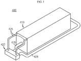
- FIG. 1 is a perspective view schematically showing an energy storage apparatus according to an embodiment of the present disclosure.
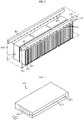
- FIG. 2 is a perspective view schematically showing some components of the energy storage apparatus according to an embodiment of the present disclosure.
- FIG. 3 is a perspective view schematically showing a battery pack, employed at the energy storage apparatus according to an embodiment of the present disclosure.
- FIG. 4 is a diagram showing an internal components of an air conditioner, employed at the energy storage apparatus according to an embodiment of the present disclosure.
- an energy storage apparatus 400 of the present disclosure may include at least one battery rack 300, a container 410 for accommodating the battery rack 300, and an air conditioner 420.
- the battery rack 300 includes a plurality of battery packs 200 arranged in one row in an upper and lower direction, and a rack case 310 for accommodating the plurality of battery packs 200.
- the plurality of battery packs 200 arranged in one row in an upper and lower direction and mounted in an accommodation portion 312 of the rack case 310 are defined as one battery rack 300.
- one rack case 310 may include a plurality of battery packs 200.
- the plurality of battery packs 200 may be configured to be accommodated in the rack case 310 to be form arranged in an upper and lower direction.
- the plurality of battery packs 200 may include a pack housing 210 and a plurality of secondary batteries (not shown) provided inside the pack housing 210 and stacked in one direction.
- the secondary battery may be a pouch-type secondary battery.
- the pouch-type secondary battery may include an electrode assembly (not shown), an electrolyte (not shown), and a pouch.
- Each secondary battery may be disposed to be vertically erect on the ground so that two wide sides are located in front and rear directions and sealing portions are located in upper, lower, left and right directions.
- each secondary battery may be configured to be erect in an upper and lower direction.
- upper, lower, front, rear, left and right directions will be set based on when viewed in the F direction.
- the pouch may be configured to have an accommodation portion with a concave shape.
- the electrode assembly and the electrolyte may be accommodated in the accommodation portion.
- each pouch includes an outer insulation layer, a metal layer and an inner adhesive layer, and the inner adhesive layers may be adhered to each other at an edge of the pouch to form a sealing portion.
- a terrace portion may be formed at left and right ends of the secondary battery, respectively, where a positive electrode lead and a negative electrode lead are formed.
- the electrode assembly is an assembly of an electrode plate coated with an electrode active material and a separator, and at least one positive electrode plate and at least one negative electrode plate may be disposed therein with the separator being interposed therebetween.
- a positive electrode tab may be provided on the positive electrode plate of the electrode assembly, and at least one positive electrode tab may be connected to the positive electrode lead.
- the positive electrode lead has one end connected to the positive electrode tab and the other end exposed out of the pouch, and the exposed portion may function as an electrode terminal of the secondary battery, for example a positive electrode terminal of the secondary battery.
- a negative electrode tab is provided on the negative electrode plate of the electrode assembly, and at least one negative electrode tab may be connected to the negative electrode lead.
- the negative electrode lead may have one end connected to the negative electrode tab and the other end exposed out of the pouch, and the exposed portion may function as an electrode terminal of the secondary battery, for example a negative electrode terminal of the secondary battery.
- the battery pack 200 may include at least one bus bar (not shown) configured to electrically interconnect the plurality of secondary batteries to each other.
- the bus bar may be made of a conductive metal, for example copper, aluminum, nickel, or the like.
- the rack case 310 may include the accommodation portion 312 with a storage space having one open side to accommodate and store the plurality of battery packs 200, respectively.
- the plurality of accommodation portions 312 may be configured such that the plurality of battery packs 200 are mounted in an upper and lower direction.
- the accommodation portions 312 may be configured such that the plurality of battery packs 200 are disposed to be spaced apart from each other at predetermined intervals.
- each of the plurality of accommodation portions 312 may include a shelf frame (not shown) configured so that the battery pack 200 is mounted to an upper portion thereof.
- the shelf frame may have a plate shape extending in a direction (a horizontal direction) perpendicular to an outer wall of the rack case 310 extending in an upper and lower direction.
- the battery pack 200 may include a temperature sensor 270 and a pack BMS 230.
- the temperature sensor 270 may be configured to measure an internal temperature of the battery pack 200.
- the temperature sensor 270 may be connected to a sensing wire 271 to communicate with the pack BMS 230.
- the temperature sensor 270 may be connected to a control unit 424 ( FIG. 4 ), explained later, through the sensing wire.
- the pack BMS 230 may be configured to transmit temperature information of the temperature sensor 270 through wireless communication.
- the pack BMS 230 may include an NFC wireless communication unit, a Bluetooth wireless communication unit, or an RFID wireless communication unit.
- the pack BMS 230 may be configured to wirelessly communicate with a rack BMS (not shown).
- the pack BMS 230 may receive internal temperature information of the battery pack 200 from the temperature sensor 270 and transmit the temperature information to the rack BMS in a wireless communication method.
- the pack BMS 230 may receive internal temperature information of the battery pack 200 from the temperature sensor 270 and transmit the temperature information through a wireless communication method to the control unit 424 ( FIG. 4 ), explained later.
- the rack case 310 may include a rack BMS (not shown) configured to enable wireless communication with the pack BMS 230.
- the rack BMS may have a receiver unit (not shown) for wireless signals, which is configured to receive the temperature information from the pack BMS 230.
- the rack BMS may receive information such as current and voltage from the pack BMS 230.
- the container 410 may have an internal space to accommodate the at least one battery rack 300.
- the container 410 may have an outer wall to form the exterior of the energy storage apparatus 400.
- the container 410 may be a general type of container 410 that may store articles therein.
- the container will not be described in detail.
- the air conditioner 420 may control a coolant to be supplied and discharged by means of the temperature sensor 270 and the control unit 424.
- the air conditioner 420 may control a supply amount and discharge amount of a coolant (not shown) based on the temperature of the battery pack 200 measured by the temperature sensor 270.
- the coolant supplied from the air conditioner 420 e.g., a cooled air
- the temperature of the coolant rises, and the heated coolant may be sucked and discharged again by the air conditioner 420.
- the air conditioner 420 may include a coolant supply part 421 and a coolant suction part 426. More specifically, the coolant supply part 421 may include an air supply duct 425, at least two blowout units 422, and a control unit 424.
- the air supply duct 425 may be configured to move a coolant having a lower temperature than the battery pack 200 to the blowout unit 422.
- the air supply duct 425 may have a moving passage through which the coolant is moved.
- the air supply duct 425 may be connected to an external heat exchange device (not shown) configured to cool the heated coolant. That is, the air supply duct 425 may be shaped to extend from the heat exchange device and pass through the outer wall of the container 410.
- FIG. 5 is a partial perspective view schematically showing a blowout unit, employed at the energy storage apparatus according to an embodiment of the present disclosure.
- each blowout unit 422 may include a nozzle having a discharge hole K1 through which the coolant is discharged.
- the nozzle may have the discharge hole K1 protruding in a discharge direction so that the discharged coolant mostly moves in one direction.
- the blowout unit 422 may discharge the coolant toward any one of the at least two battery packs 200.
- each of the at least two blowout units 422 may be configured to switch the discharge direction of the coolant individually and increase or decrease the discharge amount of the coolant individually.
- control unit 424 may be configured to control the discharge direction and the discharge amount of the coolant of each of the at least two blowout units 422.
- control unit 424 may control the degree of opening of the discharge hole K1 of the blowout unit 422 to be increased or decreased.
- control unit 424 may move the direction of the nozzle of the blowout unit 422 toward any one of the at least two battery packs 200.
- the coolant suction part 426 may be configured to suck the heated coolant, if the coolant supplied from the coolant supply part 421 is heated by absorbing heat of the battery pack 200.
- the coolant suction part 426 may include a suction duct 428 and a suction hole K2 formed in the suction duct 428.
- the present disclosure is not necessarily limited to the structural features of the suction duct 428 shown in FIG. 2 , and if necessary, the suction duct 428 may be configured to extend to the inner space of the container 410.
- the air conditioner 420 may be configured to be connected to an external heat exchange device (not shown). That is, the air conditioner 420 may receive a cooled coolant from the heat exchange device or may send a heated coolant thereto. The heat exchange device may lower the temperature of the coolant by condensing or thermally radiating the heated coolant received from the air conditioner 420.
- the present disclosure since the present disclosure includes the coolant supply part 421 having at least two blowout units 422 configured to individually switch the discharge direction of the coolant toward any one of the at least two battery packs 200 and individually increase or decrease the discharge amount of the coolant and a control unit 424 configured to control the discharge direction and the discharge amount of the coolant of each of the plurality of battery packs 200, it is possible that more coolant is brought into contact with a specific battery pack 200 requiring intensively cooling among the plurality of battery packs 200.
- each of the at least two blowout units 422 may discharge a coolant to the battery pack 200 exhibiting a highest temperature among the plurality of battery packs 200 to rapidly cool the high-temperature battery pack 200. Accordingly, it is possible to minimize the temperature deviation of the at least two battery packs 200 accommodated in the battery rack 300, thereby preventing the service life of the battery pack 200 from decreasing due to deterioration.
- the control unit 424 of the air conditioner 420 may operate an air blower 423 to supply a coolant from an external heat exchange device to the air supply duct 425.
- the control unit 424 may receive temperature information of the battery pack 200 from the temperature sensor 270 attached to the battery pack 200 and determine whether to operate the air blower 423.
- control unit 424 may be configured to adjust a blowing direction of each of the at least two blowout units 422 so that the coolant is concentrated only to some battery packs 200 exhibiting a relatively higher temperature among the at least two battery packs 200. For example, if the control unit 424 receives a temperature value higher than a reference value from the temperature sensor 270 provided to each of the at least two battery packs 200, the control unit 424 may allow a coolant to be concentrated only to some battery packs 200 exhibiting a high temperature by adjusting the discharge direction of the at least two blowout units 422 toward the battery pack 200 exceeding the reference value.
- control unit 424 is configured to adjust the blowing direction of each of the at least two blowout unit 422 so that the coolant is concentrated only to some battery packs 200 exhibiting a relatively higher temperature among the at least two battery packs 200, it is possible to perform spot cooling on a specific battery pack 200 having a relatively higher temperature than the remaining battery packs 200. That is, in the present disclosure, since only some specific battery packs that require intensive cooling among the plurality of battery packs 200 may be quickly cooled, it is possible to reduce the temperature deviation of the battery packs 200 and effectively prevent the battery pack 200 from deteriorating by quick cooling.
- control unit 424 may be configured to adjust so that the discharge amount of the blowout unit 422 discharging the coolant toward the battery pack 200 exhibiting a relatively higher temperature among the at least two battery packs 200 is larger than that of the remaining blowout unit 422.
- control unit 424 may increase the amount of coolant supplied to some battery pack 200 exhibiting a high temperature by adjusting the discharge amount of the at least two blowout units 422 toward the battery pack 200 exceeding the reference temperature value.
- the suction duct 428 of the coolant suction part 426 may have a moving space formed therein so that the coolant inside the container 410 may move to the outside of the container 410, and may have a shape extending to the outside of the container 410.
- the suction duct 428 may have a suction hole K2 configured to suck the heated coolant again.
- the blowout unit 422 may include a fixing member 422a, a body 422b, a blowout nozzle 422c, and a shutter 422d.
- the fixing member 422a may be fixed to the air supply duct 425 in a movable form. That is, the fixing member 422a may be formed in a portion of the air supply duct 425 where the blowout unit 422 needs to be formed. In addition, the fixing member 422a may be coupled to the outer wall of the air supply duct 425 by bolting or male-female fastening so as to be detachable if necessary.
- the fixing member 422a may have a ring shape.
- the fixing member 422a may be configured to be coupled to an edge portion 425a of an opening formed in the air supply duct 425.
- the fixing member 422a may have an inlet formed to communicate with the opening of the air supply duct 425.
- the body 422b may be configured to be coupled to the fixing member 422a in a movable form.
- the body 422b may have a curved surface so as to be rotatable in state of being coupled to the fixing member 422a.
- the body 422b may be configured to be rotatable in the range of 0 degrees to 100 degrees.
- the body 422b may have one end inserted into the air supply duct 425 and the other end protruding out of the air supply duct 425.
- the blowout nozzle 422c may be rotated under the control of the control unit 424.
- the blowout nozzle 422c may include a plurality of servo motors (not shown) provided with a rubber roller or belt.
- the servo motor may transmit a rotational force of the motor to the body 422b through the rubber roller or belt so that the body 422b rotates.
- the body 422b of the blowout nozzle 422c may rotate.
- the servo motor may be rotated by receiving a power from the control unit 424. More specifically, a rotary shaft of the servo motor is connected to a rotary shaft of the rubber roller, and the rubber roller may press the outer surface of the body 422b according to the rotation of the servo motor.
- the body 422b may be rotated by the force transmitted by the rubber roller.
- blowout nozzle 422c may be formed so that an end of the body 422b is opened to discharge the coolant.
- the blowout nozzle 422c may have a discharge hole K1 formed to communicate with the opening of the air supply duct 425 of the body 422b.
- a lip 422c1 protruding outward may be provided at the periphery of the discharge hole K1 of the blowout nozzle 422c to guide the discharge direction of the discharged coolant.
- the shutter 422d may be a member configured to be movable to cover at least a portion of the discharge hole K1 of the blowout nozzle 422c.
- the shutter 422d may be regarded as a damper that controls the degree of opening and closing of the discharge hole K1 of the blowout nozzle 422c.
- the shutter 422d may be controlled by the control unit 424.
- the shutter 422d may open the discharge hole K1 of the blowout nozzle 422c to change the degree of opening from 1% to 100% in order to increase the amount of coolant discharged from the blowout nozzle 422c.
- the shutter 422d may change the degree of opening of the discharge hole K1 of the blowout nozzle 422c from 100% to 0% in order to reduce the amount of coolant discharged from the blowout nozzle 422c.
- the degree of opening means the ratio of an opened area to a total area of the opening.
- the shutter 422d may be positioned inside the body 422b.
- the shutter 422d may have a curved surface to be slidable along the inner surface of the body 422b.
- the blowout unit 422 may have a moving screw 422d1 capable of moving the location of the shutter 422d. That is, the shutter 422d may be configured to move along the inner surface of the body 422b by rotating the moving screw 422d1.
- the moving screw 422d1 may be adjusted by the control unit 424.
- the moving screw 422d1 may be connected to the rotary shaft of the motor so as to receive the rotating force of the servo motor (not shown).
- the servo motor may receive a power by the control unit 424 to control the degree of rotation of the rotary shaft. That is, the control unit 424 may be configured to adjust the degree of opening and closing of the discharge hole K1 of the blowout nozzle 422c by moving the location of the shutter 422d.
- the blowout unit 422 since the blowout unit 422 includes a fixing member 422a fixed to the air supply duct 425 and having an inlet formed to communicate with the inside of the air supply duct 425, a body 422b coupled to the fixing member 422a and having a curved surface so as to be rotatable in a state of being coupled, a blowout nozzle 422c formed by opening an end of the body 422b to discharge the coolant, and a shutter 422d configured to be movable to cover at least a portion of the opening of the blowout nozzle 422c, it is possible to efficiently control the discharge direction and the discharge amount of the coolant discharged by the blowout nozzle 422c. Accordingly, in the present disclosure, a specific battery pack 200 may be cooled more quickly among at least two battery packs 200.
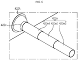
- FIG. 6 is a partial perspective view schematically showing a blowout unit, employed at an energy storage apparatus according to another embodiment of the present disclosure.
- the blowout unit 422A may further include an elongated tube 422e in the blowout nozzle 422c, when compared with the blowout unit 422 of FIG. 5 .
- the elongated tube 422e may be configured to change its length in the discharge direction according to the location of any one battery pack 200 among the at least two battery packs 200.
- the elongated tube 422e may include three tubes 422e1, 422e2, 422e3 connected to each other.
- the three tubes 422e1, 422e2, 422e3 may be configured to have different tube diameters.
- the three tubes 422e1, 422e2, 422e3 may be configured such that a tube located relatively farther from the fixing member 422a has a smaller diameter.
- a tube having a relatively small tube diameter may be inserted into a tube having a relatively large tube diameter to be movable.
- the elongated tube 422e may have a first tube 422e1, a second tube 422e2, and a third tube 422e3.
- the elongated tube 422e may be configured such that its tube diameter is reduced step by step in the order of the first tube 422e1, the second tube 422e2 and the third tube 422e3. That is, the elongated tube 422e may be configured such that the second tube 422e2 is drawn out from the first tube 422e1 and the third tube 422e3 is drawn out from the second tube 422e2 in order to extend the entire tube length.
- the elongated tube 422e may be configured such that the third tube 422e3 is inserted into the second tube 422e2 and the second tube 422e2 is inserted into the first tube 422e1 in order to reduce the total tube length.
- FIG. 7 is a partial perspective view schematically showing a battery rack according to another embodiment of the present disclosure.
- FIGS. 8 and 9 are perspective views schematically showing some components of the battery rack according to an embodiment of the present disclosure.
- a battery rack 300A may further include a guide member 430, when compared with the battery rack 300 of FIG. 2 .
- the guide member 430 may be provided in the accommodation portion 312 in which the battery pack 200 of the rack case 310 is mounted.
- the guide member 430 may include an inclined wall 432 protruding outward based on the location of the battery pack 200 so that the coolant discharged from the blowout unit 422 is guided to move to the battery pack 200.
- the guide member 430 may be provided in the accommodation portion 312 that accommodates the battery pack 200 positioned at the bottom of the battery rack 300.
- the guide member 430 may include the inclined wall 432 protruding outward based on the location of the battery pack 200 so that the coolant may move to the battery pack 200. Accordingly, the guide member 430 may reduce the amount of coolant dispersed around the battery pack 200, thereby helping to perform effective point cooling.
- the guide member 430 having an inclined wall 432 protruding outward based on the location of the battery pack 200 is provided in the accommodation portion 312 in which the battery pack 200 is mounted so that the coolant is guided to move to the battery pack 200, it is possible to effectively deliver the coolant to the battery pack 200 located at a relatively far distance from the blowout unit 422 among the plurality of battery packs 200.
- the guide member 430 by using the guide member 430, it is possible to solve the problem that after the blowout unit 422 discharges a cooling air, the point cooling efficiency deteriorates as the cooling air spreads seriously in all directions due to a long moving distance of the cooling air.
- the inclined wall 432 may be configured to be connected using a hinge structure H1 so that the degree of outward protrusion thereof may be changed based on the location of the battery pack 200.
- the rotation of the inclined wall 432 may be controlled by the control unit 424.
- a rotary shaft of the hinge structure H1 of the inclined wall 432 may be connected to a servo motor (not shown).
- the inclined wall 432 of the guide member 430 may be rotated to be unfolded to protrude outward or to be folded inward by rotation of the servo motor supplied with a power from the control unit 424.
- the guide member 430 is connected using the hinge structure H1 so that the degree of outward protrusion of the inclined wall 432 may be changed based on the location of the battery pack 200, it is possible to increase the amount of coolant that comes into contact with a specific battery pack 200 by spreading the inclined wall 432 of the guide member 430. Accordingly, in the present disclosure, it is possible to solve the problem that the point cooling efficiency deteriorates according to the distance between the blowout unit 422 and the battery pack 200.
- the guide member 430 may include a conduction portion 434.
- the conduction portion 434 may be made of a thermally conductive material.
- the thermally conductive material may be aluminum or copper.
- the conduction portion 434 may have a shape extending from an inner end of the inclined wall 432 into the battery rack 300. That is, the conduction portion 434 may be configured to contact at least a portion of the outer surface of the battery pack 200.
- the conduction portion 434 may conduct the heat received from the battery pack 200 to the inclined wall 432.
- the guide member 430 since the guide member 430 includes a conduction portion 434 having a thermally conductive material and configured to extend from the inner end of the inclined wall 432 into the battery rack 300, it is possible to cool the rear portion of the battery pack 200 located inside the accommodation portion 312 of the battery rack 300. Accordingly, in the present disclosure, it is possible to maximize the point cooling efficiency of the battery pack 200 through the conduction portion 434 of the guide member 430.
- FIG. 10 is a perspective view schematically showing an internal configuration of an energy storage apparatus according to another embodiment of the present disclosure.
- a suction duct 428B may extend into the container 410.
- the suction duct 428B may be configured such that the location of the suction hole K2 is movable.
- the suction duct 428B may be configured such that at least a portion thereof may be moved. As the location of a portion of the suction duct 428B moves, the location of the suction hole K2 formed in the suction duct 428B may also be moved together.
- the location of the suction hole K2 of the suction duct 428B may be moved closer to the battery rack 300 having a relatively high temperature so that a coolant may be concentrated to the battery rack 300 in which the battery packs 200 mounted therein have a relatively high average temperature, among the plurality of battery racks 300.
- the length of the suction duct 428B inserted into the container 410 may be controlled to decrease or increase.
- the suction duct 428B may be configured by coupling a plurality of divided ducts.
- the extension length of the suction duct 428B may be reduced by pressing an extended end of the suction duct 428B in one direction.
- the extension length of the suction duct 428B may be increased by pulling a distal end of the suction duct 428B in the other direction.
- the push bar 429 may be connected to the end of the suction duct 428B.
- the control unit 424 ( FIG. 4 ) of the air conditioner 420 may control a portion of the suction duct 428B to move by transmitting an electric signal so that the length of the suction duct 428B is increased or decreased.
- the suction duct 428B is configured such that the location of the suction hole K2 is movable, it is possible to control a coolant to be concentrated to a battery rack 300 requiring more cooling among the plurality of battery racks 300. Accordingly, it is possible to effectively reduce the temperature deviation among the plurality of battery racks 300. Ultimately, it is possible to effectively extend the service life of the energy storage apparatus 400B.
- an energy storage system may include two or more energy storage apparatuses described above.
- the energy storage system may include a control tower that controls charging, discharging and power interruption of a plurality of energy storage apparatuses.
- the energy storage apparatus 400 of Example 1 has the same configuration as the energy storage apparatus 400 shown in FIG. 2 . That is, the energy storage apparatus 400 of Example 1 includes 30 battery racks provided in the container 410, and 17 battery packs 200 are arranged in an upper and lower direction in each battery rack 300.
- the air supply ducts 425 are provided at left and right top ends of the container 410, and 15 blowout units for supplying a coolant are formed to be spaced apart from each other at predetermined intervals.
- the suction holes K2 are formed in the front and rear walls of the container 410, respectively, so as to suck a heated coolant and discharge the sucked coolant to the outside.
- the temperature sensor is provided on a portion of the outer surface of the battery pack 200 at a location close to the inner side of the accommodation portion of the rack case.
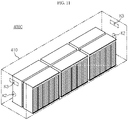
- An energy storage apparatus 400C of Comparative Example 1 does not include an air supply duct and a blowout unit, as shown in FIG. 11 , and supply holes K3 are formed at top ends of the front and rear walls of the container 410 instead.
- the suction holes K2 are formed in the front and rear walls of the container 410, respectively, so as to suck a heated coolant and discharge the sucked coolant to the outside.
- Other components are configured identical to those of the energy storage apparatus 400 of Example 1.
- Example 1 and Comparative Example 1 of the present disclosure were evaluated by computational fluid dynamics simulation (C.F.D Simulation, product name: Siemens STAR-CCM+, version: 13.04.010), which simulates the interaction of fluid and gas through a computer.
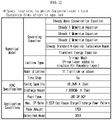
- the specifications to which the simulation is applied are shown in the table of FIG. 12 .
- the simulation experiment results of Example 1 and Comparative Example 1 are shown in the tables of FIGS. 13 and 14 , respectively.
- the energy storage apparatus of Example 1 was able to lower the average temperature of the entire battery packs by using the air supply duct having the blowout unit, compared to Comparative Example 1 not including the air supply duct. That is, the overall cooling performance of the battery packs provided to the energy storage apparatus was improved. In addition, by reducing the maximum deviation of the entire battery racks, it was found that the temperature imbalance among the battery racks was reduced. In other words, it was found that the energy storage apparatus had improved cooling efficiency and proper cooling air supply capacity.
Landscapes
- Chemical & Material Sciences (AREA)
- Chemical Kinetics & Catalysis (AREA)
- Electrochemistry (AREA)
- General Chemical & Material Sciences (AREA)
- Engineering & Computer Science (AREA)
- Manufacturing & Machinery (AREA)
- Automation & Control Theory (AREA)
- Secondary Cells (AREA)
- Battery Mounting, Suspending (AREA)
Abstract
Description
- The present disclosure relates to an energy storage apparatus and an energy storage system, and more particularly, to an energy storage apparatus and an energy storage system with improved cooling efficiency and proper coolant supply capability.
- The present application claims priority to
Korean Patent Application No. 10-2020-0001059 filed on January 3, 2020 - Secondary batteries currently commercialized include nickel cadmium batteries, nickel hydrogen batteries, nickel zinc batteries, lithium secondary batteries and so on. Among them, the lithium secondary batteries are more highlighted in comparison to nickel-based secondary batteries due to advantages such as free charging and discharging, caused by substantially no memory effect, very low self-discharge rate, and high energy density.
- The lithium secondary battery mainly uses lithium-based oxides and carbonaceous materials as a positive electrode active material and a negative electrode active material, respectively. The lithium secondary battery includes an electrode assembly in which a positive electrode plate coated with the positive electrode active material and a negative electrode plate coated with the negative electrode active material are disposed with a separator being interposed therebetween, and an exterior, namely a battery pouch exterior, hermetically containing the electrode assembly together with an electrolyte.
- Recently, secondary batteries are widely used not only in small devices such as portable electronic devices, but also in middle-sized or large-sized devices such as vehicles and energy storage devices. When used in such a middle-sized device, a large number of secondary batteries are electrically connected to increase capacity and output. In particular, pouch-type secondary batteries are widely used in such middle-sized and large-sized devices due to the advantage of easy stacking.
- Meanwhile, recently, as the need for a large-capacity structure increases along with the use as an energy storage source, there is an increasing demand for an energy storage apparatus that includes a plurality of battery racks, each having a plurality of battery packs respectively accommodating a plurality of secondary batteries therein, a container for storing the plurality of battery racks therein, and an air conditioner for cooling the plurality of battery racks.
- In addition, in a conventional general air conditioner of the energy storage apparatus, temperature deviation inevitably occurs between the plurality of battery racks and between the plurality of battery packs according to the locations of the plurality of battery racks and the plurality of battery packs.
- For example, in a conventional general air conditioning method in a battery system, the surface of the battery pack is cooled while supplying a cold cooling air to an upper portion or a lower portion of a container wall. However, the air conditioning method has a problem in that the temperature deviation among the plurality of battery packs may easily increase depending on the operating conditions (weather, charging/discharging patterns, and air conditioning types) of the energy storage apparatus. Accordingly, among the plurality of battery packs, any battery pack having a high temperature may be deteriorated to shorten the lifespan, thereby increasing the maintenance cost of the energy storage apparatus.
- Accordingly, there is a need for a method to effectively reduce temperature variation among the plurality of battery packs accommodated in the container.
- The present disclosure is designed to solve the problems of the related art, and therefore the present disclosure is directed to providing an energy storage apparatus and an energy storage system with improved cooling efficiency and proper coolant supply capability.
- These and other objects and advantages of the present disclosure may be understood from the following detailed description and will become more fully apparent from the exemplary embodiments of the present disclosure. Also, it will be easily understood that the objects and advantages of the present disclosure may be realized by the means shown in the appended claims and combinations thereof.
- In one aspect of the present disclosure, there is provided an energy storage apparatus, comprising:
- at least one battery rack having at least two battery packs;
- a container configured to accommodate the at least one battery rack; and
- an air conditioner provided with a coolant supply part, which includes at least two blowout units respectively having a nozzle with a discharge hole through which a coolant is discharged and configured to individually switch a discharge direction of the coolant toward any one of the at least two battery packs and individually increase or decrease a discharge amount of the coolant and a control unit configured to adjust the discharge direction and the discharge amount of the coolant of each of the at least two blowout units, and a coolant suction part configured to suck a heated coolant inside the container.
- Moreover, the control unit may be configured to adjust a blowing direction of each of the at least two blowout units so that the coolant is concentrated only to some battery packs exhibiting a relatively higher temperature among the at least two battery packs.
- In addition, the control unit may be configured to adjust so that a discharge amount of a blowout unit discharging the coolant toward a battery pack exhibiting a relatively higher temperature among the at least two battery packs is greater than a discharge amount of the remaining blowout unit.
- Further, the coolant supply part may include an air supply duct having a moving passage for moving the coolant to the blowout unit, and
the coolant suction part may include a suction duct having a suction hole for sucking the heated coolant inside the container again and configured to extend so that the sucked coolant is moved to the outside of the container. - Also, the blowout unit may include:
- a fixing member fixed to the air supply duct and having an inlet formed to communicate with the air supply duct;
- a body coupled to the fixing member and configured to have a curved surface that is rotatable in a coupled state;
- a blowout nozzle having a discharge hole formed by opening an end of the body to discharge the coolant; and
- a shutter configured movably to cover at least a portion of the discharge hole of the blowout nozzle.
- In addition, the blowout nozzle may include an elongated tube configured to change a length in a discharge direction according to a location of any one battery pack among the at least two battery packs.
- Further, the battery rack may include a guide member having an inclined wall configured to protrude outward based on a location of the battery pack so that the coolant around the battery pack is guided to move to the battery pack.
- Also, in the guide member, the inclined wall may be connected using a hinge structure so that the degree of outward protrusion thereof is changed based on the location of the battery pack.
- Moreover, the guide member may include a conduction portion made of a thermally conductive material and configured to extend into the battery rack from an inner end of the inclined wall.
- In addition, the suction duct may be configured to be at least partially movable so that at least a portion of the suction hole is moved to another location.
- In another aspect of the present disclosure, there is also provided an energy storage system, comprising at least two energy storage apparatuses as above.
- According to an embodiment of the present disclosure, since the present disclosure includes the coolant supply part having at least two blowout units configured to individually switch the discharge direction of the coolant toward any one of the at least two battery packs and individually increase or decrease the discharge amount of the coolant and a control unit configured to control the discharge direction and the discharge amount of the coolant of each of the plurality of battery packs, it is possible that more coolant is brought into contact with a specific battery pack requiring intensively cooling among the plurality of battery packs.
- Also, according to an embodiment of the present disclosure, since the control unit is configured to adjust the blowing direction of each of the at least two blowout unit so that the coolant is concentrated only to some battery packs exhibiting a relatively higher temperature among the at least two battery packs, it is possible to perform spot cooling on a specific battery pack having a relatively higher temperature than the remaining battery packs. That is, in the present disclosure, since only some specific battery packs that require intensive cooling among the plurality of battery packs may be quickly cooled, it is possible to reduce the temperature deviation of the battery packs and effectively prevent the battery pack from deteriorating by quick cooling.
- In addition, according to an embodiment of the present disclosure, since the blowout unit includes a fixing member fixed to the air supply duct and having an inlet formed to communicate with the inside of the air supply duct, a body coupled to the fixing member and having a curved surface so as to be rotatable in a state of being coupled, a blowout nozzle formed by opening an end of the body to discharge the coolant, and a shutter configured to be movable to cover at least a portion of the opening of the blowout nozzle, it is possible to efficiently control the discharge direction and the discharge amount of the coolant discharged by the blowout nozzle. Accordingly, in the present disclosure, a battery pack requiring intensive cooling may be cooled more quickly among at least two battery packs.
- Further, according to another embodiment of the present disclosure, in the battery rack, since the guide member having an inclined wall protruding outward based on the location of the battery pack is provided in the accommodation portion in which the battery pack is mounted so that the coolant is guided to move to the battery pack, it is possible to effectively deliver the coolant to the battery pack located at a relatively far distance from the blowout unit among the plurality of battery packs. In other words, in the present disclosure, by using the guide member, it is possible to solve the problem that after the blowout unit discharges a cooling air, the point cooling efficiency deteriorates as the cooling air spreads seriously in all directions due to a long moving distance of the cooling air.
- Also, according to another embodiment of the present disclosure, since the guide member is connected using the hinge structure so that the degree of outward protrusion of the inclined wall may be changed based on the location of the battery pack, it is possible to increase the amount of coolant that comes into contact with a specific battery pack by spreading the inclined wall of the guide member. Accordingly, in the present disclosure, it is possible to solve the problem that the point cooling efficiency deteriorates according to the distance between the blowout unit and the battery pack.
- Moreover, according to another embodiment of the present disclosure, since the suction duct is configured such that the location of the suction hole is movable, it is possible to control a coolant to be concentrated to a battery rack requiring more cooling among the plurality of battery racks. Accordingly, it is possible to effectively reduce the temperature deviation among the plurality of battery racks. Ultimately, it is possible to effectively extend the service life of the energy storage apparatus.
- The accompanying drawings illustrate a preferred embodiment of the present disclosure and together with the foregoing disclosure, serve to provide further understanding of the technical features of the present disclosure, and thus, the present disclosure is not construed as being limited to the drawing.
-
FIG. 1 is a perspective view schematically showing an energy storage apparatus according to an embodiment of the present disclosure. -
FIG. 2 is a perspective view schematically showing some components of the energy storage apparatus according to an embodiment of the present disclosure. -
FIG. 3 is a perspective view schematically showing a battery pack, employed at the energy storage apparatus according to an embodiment of the present disclosure. -
FIG. 4 is a diagram showing an internal components of an air conditioner, employed at the energy storage apparatus according to an embodiment of the present disclosure. -
FIG. 5 is a partial perspective view schematically showing a blowout unit, employed at the energy storage apparatus according to an embodiment of the present disclosure. -
FIG. 6 is a partial perspective view schematically showing a blowout unit, employed at an energy storage apparatus according to another embodiment of the present disclosure. -
FIG. 7 is a partial perspective view schematically showing a battery rack according to another embodiment of the present disclosure. -
FIGS. 8 and 9 are perspective views schematically showing some components of the battery rack according to an embodiment of the present disclosure. -
FIG. 10 is a perspective view schematically showing an internal configuration of an energy storage apparatus according to another embodiment of the present disclosure. -
FIG. 11 is a perspective view schematically showing some components of an energy storage apparatus according to Comparative Example 1 of the present disclosure. -
FIG. 12 is a table showing the specification to which the simulation of the experimental example of the present disclosure is applied. -
FIG. 13 is a table showing the simulation analysis result of Example 1 of the experimental example of the present disclosure. -
FIG. 14 is a table showing the simulation analysis result of Comparative Example 1 of the experimental example of the present disclosure. - Hereinafter, preferred embodiments of the present disclosure will be described in detail with reference to the accompanying drawings. Prior to the description, it should be understood that the terms used in the specification and the appended claims should not be construed as limited to general and dictionary meanings, but interpreted based on the meanings and concepts corresponding to technical aspects of the present disclosure on the basis of the principle that the inventor is allowed to define terms appropriately for the best explanation.
- Therefore, the description proposed herein is just a preferable example for the purpose of illustrations only, not intended to limit the scope of the disclosure, so it should be understood that other equivalents and modifications could be made thereto without departing from the scope of the disclosure.
-
FIG. 1 is a perspective view schematically showing an energy storage apparatus according to an embodiment of the present disclosure.FIG. 2 is a perspective view schematically showing some components of the energy storage apparatus according to an embodiment of the present disclosure.FIG. 3 is a perspective view schematically showing a battery pack, employed at the energy storage apparatus according to an embodiment of the present disclosure. Also,FIG. 4 is a diagram showing an internal components of an air conditioner, employed at the energy storage apparatus according to an embodiment of the present disclosure. - Referring to
FIGS. 1 to 4 , anenergy storage apparatus 400 of the present disclosure may include at least onebattery rack 300, acontainer 410 for accommodating thebattery rack 300, and anair conditioner 420. - Here, the
battery rack 300 includes a plurality of battery packs 200 arranged in one row in an upper and lower direction, and arack case 310 for accommodating the plurality of battery packs 200. Here, regarding thebattery rack 300 of the present disclosure, the plurality of battery packs 200 arranged in one row in an upper and lower direction and mounted in anaccommodation portion 312 of therack case 310 are defined as onebattery rack 300. In addition, onerack case 310 may include a plurality of battery packs 200. - First, the plurality of battery packs 200 may be configured to be accommodated in the
rack case 310 to be form arranged in an upper and lower direction. In addition, the plurality of battery packs 200 may include a pack housing 210 and a plurality of secondary batteries (not shown) provided inside the pack housing 210 and stacked in one direction. - Specifically, the secondary battery may be a pouch-type secondary battery. In particular, the pouch-type secondary battery may include an electrode assembly (not shown), an electrolyte (not shown), and a pouch.
- Each secondary battery may be disposed to be vertically erect on the ground so that two wide sides are located in front and rear directions and sealing portions are located in upper, lower, left and right directions. In other words, each secondary battery may be configured to be erect in an upper and lower direction. Meanwhile, in this specification, unless otherwise specified, upper, lower, front, rear, left and right directions will be set based on when viewed in the F direction.
- Here, the pouch may be configured to have an accommodation portion with a concave shape. In addition, the electrode assembly and the electrolyte may be accommodated in the accommodation portion. In addition, each pouch includes an outer insulation layer, a metal layer and an inner adhesive layer, and the inner adhesive layers may be adhered to each other at an edge of the pouch to form a sealing portion. Further, a terrace portion may be formed at left and right ends of the secondary battery, respectively, where a positive electrode lead and a negative electrode lead are formed.
- In addition, the electrode assembly is an assembly of an electrode plate coated with an electrode active material and a separator, and at least one positive electrode plate and at least one negative electrode plate may be disposed therein with the separator being interposed therebetween. In addition, a positive electrode tab may be provided on the positive electrode plate of the electrode assembly, and at least one positive electrode tab may be connected to the positive electrode lead.
- Here, the positive electrode lead has one end connected to the positive electrode tab and the other end exposed out of the pouch, and the exposed portion may function as an electrode terminal of the secondary battery, for example a positive electrode terminal of the secondary battery.
- In addition, a negative electrode tab is provided on the negative electrode plate of the electrode assembly, and at least one negative electrode tab may be connected to the negative electrode lead. Also, the negative electrode lead may have one end connected to the negative electrode tab and the other end exposed out of the pouch, and the exposed portion may function as an electrode terminal of the secondary battery, for example a negative electrode terminal of the secondary battery.
- Moreover, the
battery pack 200 may include at least one bus bar (not shown) configured to electrically interconnect the plurality of secondary batteries to each other. Specifically, the bus bar may be made of a conductive metal, for example copper, aluminum, nickel, or the like. - Meanwhile, referring to
FIG. 2 again, therack case 310 may include theaccommodation portion 312 with a storage space having one open side to accommodate and store the plurality of battery packs 200, respectively. The plurality ofaccommodation portions 312 may be configured such that the plurality of battery packs 200 are mounted in an upper and lower direction. Alternatively, theaccommodation portions 312 may be configured such that the plurality of battery packs 200 are disposed to be spaced apart from each other at predetermined intervals. - Further, each of the plurality of
accommodation portions 312 may include a shelf frame (not shown) configured so that thebattery pack 200 is mounted to an upper portion thereof. Specifically, the shelf frame may have a plate shape extending in a direction (a horizontal direction) perpendicular to an outer wall of therack case 310 extending in an upper and lower direction. - In addition, the
battery pack 200 may include atemperature sensor 270 and apack BMS 230. Thetemperature sensor 270 may be configured to measure an internal temperature of thebattery pack 200. For example, thetemperature sensor 270 may be connected to asensing wire 271 to communicate with thepack BMS 230. Alternatively, thetemperature sensor 270 may be connected to a control unit 424 (FIG. 4 ), explained later, through the sensing wire. - In addition, the
pack BMS 230 may be configured to transmit temperature information of thetemperature sensor 270 through wireless communication. To this end, thepack BMS 230 may include an NFC wireless communication unit, a Bluetooth wireless communication unit, or an RFID wireless communication unit. Thepack BMS 230 may be configured to wirelessly communicate with a rack BMS (not shown). For example, thepack BMS 230 may receive internal temperature information of thebattery pack 200 from thetemperature sensor 270 and transmit the temperature information to the rack BMS in a wireless communication method. Alternatively, thepack BMS 230 may receive internal temperature information of thebattery pack 200 from thetemperature sensor 270 and transmit the temperature information through a wireless communication method to the control unit 424 (FIG. 4 ), explained later. - Moreover, the
rack case 310 may include a rack BMS (not shown) configured to enable wireless communication with thepack BMS 230. The rack BMS may have a receiver unit (not shown) for wireless signals, which is configured to receive the temperature information from thepack BMS 230. In addition, the rack BMS may receive information such as current and voltage from thepack BMS 230. - Meanwhile, the
container 410 may have an internal space to accommodate the at least onebattery rack 300. Thecontainer 410 may have an outer wall to form the exterior of theenergy storage apparatus 400. For example, thecontainer 410 may be a general type ofcontainer 410 that may store articles therein. Here, the container will not be described in detail. - Meanwhile, the
air conditioner 420 may control a coolant to be supplied and discharged by means of thetemperature sensor 270 and thecontrol unit 424. Theair conditioner 420 may control a supply amount and discharge amount of a coolant (not shown) based on the temperature of thebattery pack 200 measured by thetemperature sensor 270. When the coolant supplied from the air conditioner 420 (e.g., a cooled air) comes into contact with thebattery pack 200, the temperature of the coolant rises, and the heated coolant may be sucked and discharged again by theair conditioner 420. - Specifically, the
air conditioner 420 may include acoolant supply part 421 and acoolant suction part 426. More specifically, thecoolant supply part 421 may include anair supply duct 425, at least twoblowout units 422, and acontrol unit 424. - First, the
air supply duct 425 may be configured to move a coolant having a lower temperature than thebattery pack 200 to theblowout unit 422. Theair supply duct 425 may have a moving passage through which the coolant is moved. For example, as shown inFIG. 2 , theair supply duct 425 may be connected to an external heat exchange device (not shown) configured to cool the heated coolant. That is, theair supply duct 425 may be shaped to extend from the heat exchange device and pass through the outer wall of thecontainer 410. -
FIG. 5 is a partial perspective view schematically showing a blowout unit, employed at the energy storage apparatus according to an embodiment of the present disclosure. - Referring to
FIG. 5 along withFIGS. 1 to 4 , eachblowout unit 422 may include a nozzle having a discharge hole K1 through which the coolant is discharged. The nozzle may have the discharge hole K1 protruding in a discharge direction so that the discharged coolant mostly moves in one direction. Theblowout unit 422 may discharge the coolant toward any one of the at least two battery packs 200. In addition, each of the at least twoblowout units 422 may be configured to switch the discharge direction of the coolant individually and increase or decrease the discharge amount of the coolant individually. - Further, the
control unit 424 may be configured to control the discharge direction and the discharge amount of the coolant of each of the at least twoblowout units 422. For example, thecontrol unit 424 may control the degree of opening of the discharge hole K1 of theblowout unit 422 to be increased or decreased. In addition, thecontrol unit 424 may move the direction of the nozzle of theblowout unit 422 toward any one of the at least two battery packs 200. - In addition, the
coolant suction part 426 may be configured to suck the heated coolant, if the coolant supplied from thecoolant supply part 421 is heated by absorbing heat of thebattery pack 200. For example, thecoolant suction part 426 may include asuction duct 428 and a suction hole K2 formed in thesuction duct 428. The present disclosure is not necessarily limited to the structural features of thesuction duct 428 shown inFIG. 2 , and if necessary, thesuction duct 428 may be configured to extend to the inner space of thecontainer 410. - Moreover, the
air conditioner 420 may be configured to be connected to an external heat exchange device (not shown). That is, theair conditioner 420 may receive a cooled coolant from the heat exchange device or may send a heated coolant thereto. The heat exchange device may lower the temperature of the coolant by condensing or thermally radiating the heated coolant received from theair conditioner 420. - Therefore, according to this configuration of the present disclosure, since the present disclosure includes the
coolant supply part 421 having at least twoblowout units 422 configured to individually switch the discharge direction of the coolant toward any one of the at least twobattery packs 200 and individually increase or decrease the discharge amount of the coolant and acontrol unit 424 configured to control the discharge direction and the discharge amount of the coolant of each of the plurality of battery packs 200, it is possible that more coolant is brought into contact with aspecific battery pack 200 requiring intensively cooling among the plurality of battery packs 200. - For example, each of the at least two
blowout units 422 may discharge a coolant to thebattery pack 200 exhibiting a highest temperature among the plurality of battery packs 200 to rapidly cool the high-temperature battery pack 200. Accordingly, it is possible to minimize the temperature deviation of the at least twobattery packs 200 accommodated in thebattery rack 300, thereby preventing the service life of thebattery pack 200 from decreasing due to deterioration. - Referring to
FIG. 4 again along withFIG. 2 , thecontrol unit 424 of theair conditioner 420 may operate anair blower 423 to supply a coolant from an external heat exchange device to theair supply duct 425. In this case, thecontrol unit 424 may receive temperature information of thebattery pack 200 from thetemperature sensor 270 attached to thebattery pack 200 and determine whether to operate theair blower 423. - In addition, the
control unit 424 may be configured to adjust a blowing direction of each of the at least twoblowout units 422 so that the coolant is concentrated only to some battery packs 200 exhibiting a relatively higher temperature among the at least two battery packs 200. For example, if thecontrol unit 424 receives a temperature value higher than a reference value from thetemperature sensor 270 provided to each of the at least twobattery packs 200, thecontrol unit 424 may allow a coolant to be concentrated only to some battery packs 200 exhibiting a high temperature by adjusting the discharge direction of the at least twoblowout units 422 toward thebattery pack 200 exceeding the reference value. - Therefore, according to this configuration of the present disclosure, since the
control unit 424 is configured to adjust the blowing direction of each of the at least twoblowout unit 422 so that the coolant is concentrated only to some battery packs 200 exhibiting a relatively higher temperature among the at least twobattery packs 200, it is possible to perform spot cooling on aspecific battery pack 200 having a relatively higher temperature than the remaining battery packs 200. That is, in the present disclosure, since only some specific battery packs that require intensive cooling among the plurality of battery packs 200 may be quickly cooled, it is possible to reduce the temperature deviation of the battery packs 200 and effectively prevent thebattery pack 200 from deteriorating by quick cooling. - Moreover, the
control unit 424 may be configured to adjust so that the discharge amount of theblowout unit 422 discharging the coolant toward thebattery pack 200 exhibiting a relatively higher temperature among the at least two battery packs 200 is larger than that of the remainingblowout unit 422. - For example, if the
control unit 424 receives a temperature value higher than the reference value from thetemperature sensor 270 provided to each of the at least twobattery packs 200, thecontrol unit 424 may increase the amount of coolant supplied to somebattery pack 200 exhibiting a high temperature by adjusting the discharge amount of the at least twoblowout units 422 toward thebattery pack 200 exceeding the reference temperature value. - Meanwhile, referring to
FIG. 2 again, thesuction duct 428 of thecoolant suction part 426 may have a moving space formed therein so that the coolant inside thecontainer 410 may move to the outside of thecontainer 410, and may have a shape extending to the outside of thecontainer 410. In addition, thesuction duct 428 may have a suction hole K2 configured to suck the heated coolant again. - Referring to
FIGS. 2 ,4 and 5 again, theblowout unit 422 may include a fixingmember 422a, abody 422b, ablowout nozzle 422c, and ashutter 422d. - Specifically, the fixing
member 422a may be fixed to theair supply duct 425 in a movable form. That is, the fixingmember 422a may be formed in a portion of theair supply duct 425 where theblowout unit 422 needs to be formed. In addition, the fixingmember 422a may be coupled to the outer wall of theair supply duct 425 by bolting or male-female fastening so as to be detachable if necessary. - For example, the fixing
member 422a may have a ring shape. In addition, the fixingmember 422a may be configured to be coupled to anedge portion 425a of an opening formed in theair supply duct 425. The fixingmember 422a may have an inlet formed to communicate with the opening of theair supply duct 425. - In addition, the
body 422b may be configured to be coupled to the fixingmember 422a in a movable form. For example, thebody 422b may have a curved surface so as to be rotatable in state of being coupled to the fixingmember 422a. In this case, thebody 422b may be configured to be rotatable in the range of 0 degrees to 100 degrees. - Further, the
body 422b may have one end inserted into theair supply duct 425 and the other end protruding out of theair supply duct 425. In addition, theblowout nozzle 422c may be rotated under the control of thecontrol unit 424. For example, theblowout nozzle 422c may include a plurality of servo motors (not shown) provided with a rubber roller or belt. - Moreover, the servo motor may transmit a rotational force of the motor to the
body 422b through the rubber roller or belt so that thebody 422b rotates. Thus, as the servo motor rotates, thebody 422b of theblowout nozzle 422c may rotate. In addition, the servo motor may be rotated by receiving a power from thecontrol unit 424. More specifically, a rotary shaft of the servo motor is connected to a rotary shaft of the rubber roller, and the rubber roller may press the outer surface of thebody 422b according to the rotation of the servo motor. In addition, thebody 422b may be rotated by the force transmitted by the rubber roller. - Further, the
blowout nozzle 422c may be formed so that an end of thebody 422b is opened to discharge the coolant. Theblowout nozzle 422c may have a discharge hole K1 formed to communicate with the opening of theair supply duct 425 of thebody 422b. In addition, a lip 422c1 protruding outward may be provided at the periphery of the discharge hole K1 of theblowout nozzle 422c to guide the discharge direction of the discharged coolant. - In addition, the
shutter 422d may be a member configured to be movable to cover at least a portion of the discharge hole K1 of theblowout nozzle 422c. In other words, theshutter 422d may be regarded as a damper that controls the degree of opening and closing of the discharge hole K1 of theblowout nozzle 422c. - Also, the
shutter 422d may be controlled by thecontrol unit 424. Theshutter 422d may open the discharge hole K1 of theblowout nozzle 422c to change the degree of opening from 1% to 100% in order to increase the amount of coolant discharged from theblowout nozzle 422c. Alternatively, as a converse example, theshutter 422d may change the degree of opening of the discharge hole K1 of theblowout nozzle 422c from 100% to 0% in order to reduce the amount of coolant discharged from theblowout nozzle 422c. Here, "the degree of opening" means the ratio of an opened area to a total area of the opening. - In addition, the
shutter 422d may be positioned inside thebody 422b. Theshutter 422d may have a curved surface to be slidable along the inner surface of thebody 422b. Theblowout unit 422 may have a moving screw 422d1 capable of moving the location of theshutter 422d. That is, theshutter 422d may be configured to move along the inner surface of thebody 422b by rotating the moving screw 422d1. - Also, the moving screw 422d1 may be adjusted by the
control unit 424. For example, the moving screw 422d1 may be connected to the rotary shaft of the motor so as to receive the rotating force of the servo motor (not shown). In addition, the servo motor may receive a power by thecontrol unit 424 to control the degree of rotation of the rotary shaft. That is, thecontrol unit 424 may be configured to adjust the degree of opening and closing of the discharge hole K1 of theblowout nozzle 422c by moving the location of theshutter 422d. - Therefore, according to this configuration of the present disclosure, since the
blowout unit 422 includes a fixingmember 422a fixed to theair supply duct 425 and having an inlet formed to communicate with the inside of theair supply duct 425, abody 422b coupled to the fixingmember 422a and having a curved surface so as to be rotatable in a state of being coupled, ablowout nozzle 422c formed by opening an end of thebody 422b to discharge the coolant, and ashutter 422d configured to be movable to cover at least a portion of the opening of theblowout nozzle 422c, it is possible to efficiently control the discharge direction and the discharge amount of the coolant discharged by theblowout nozzle 422c. Accordingly, in the present disclosure, aspecific battery pack 200 may be cooled more quickly among at least two battery packs 200. -
FIG. 6 is a partial perspective view schematically showing a blowout unit, employed at an energy storage apparatus according to another embodiment of the present disclosure. - Referring to
FIG. 6 along withFIGS. 2 and4 , theblowout unit 422A according to another embodiment may further include anelongated tube 422e in theblowout nozzle 422c, when compared with theblowout unit 422 ofFIG. 5 . Theelongated tube 422e may be configured to change its length in the discharge direction according to the location of any onebattery pack 200 among the at least two battery packs 200. - For example, the
elongated tube 422e may include three tubes 422e1, 422e2, 422e3 connected to each other. The three tubes 422e1, 422e2, 422e3 may be configured to have different tube diameters. The three tubes 422e1, 422e2, 422e3 may be configured such that a tube located relatively farther from the fixingmember 422a has a smaller diameter. In addition, among the three tubes 422e1, 422e2, 422e3, a tube having a relatively small tube diameter may be inserted into a tube having a relatively large tube diameter to be movable. - For example, the
elongated tube 422e may have a first tube 422e1, a second tube 422e2, and a third tube 422e3. Theelongated tube 422e may be configured such that its tube diameter is reduced step by step in the order of the first tube 422e1, the second tube 422e2 and the third tube 422e3. That is, theelongated tube 422e may be configured such that the second tube 422e2 is drawn out from the first tube 422e1 and the third tube 422e3 is drawn out from the second tube 422e2 in order to extend the entire tube length. Conversely, theelongated tube 422e may be configured such that the third tube 422e3 is inserted into the second tube 422e2 and the second tube 422e2 is inserted into the first tube 422e1 in order to reduce the total tube length. -
FIG. 7 is a partial perspective view schematically showing a battery rack according to another embodiment of the present disclosure. Also,FIGS. 8 and 9 are perspective views schematically showing some components of the battery rack according to an embodiment of the present disclosure. - Referring to
FIGS. 7 to 9 , abattery rack 300A according to another embodiment of the present disclosure may further include aguide member 430, when compared with thebattery rack 300 ofFIG. 2 . Theguide member 430 may be provided in theaccommodation portion 312 in which thebattery pack 200 of therack case 310 is mounted. Theguide member 430 may include aninclined wall 432 protruding outward based on the location of thebattery pack 200 so that the coolant discharged from theblowout unit 422 is guided to move to thebattery pack 200. - For example, as shown in
FIG. 7 , theguide member 430 may be provided in theaccommodation portion 312 that accommodates thebattery pack 200 positioned at the bottom of thebattery rack 300. Theguide member 430 may include theinclined wall 432 protruding outward based on the location of thebattery pack 200 so that the coolant may move to thebattery pack 200. Accordingly, theguide member 430 may reduce the amount of coolant dispersed around thebattery pack 200, thereby helping to perform effective point cooling. - Therefore, according to this configuration of the present disclosure, in the
battery rack 300, since theguide member 430 having aninclined wall 432 protruding outward based on the location of thebattery pack 200 is provided in theaccommodation portion 312 in which thebattery pack 200 is mounted so that the coolant is guided to move to thebattery pack 200, it is possible to effectively deliver the coolant to thebattery pack 200 located at a relatively far distance from theblowout unit 422 among the plurality of battery packs 200. In other words, in the present disclosure, by using theguide member 430, it is possible to solve the problem that after theblowout unit 422 discharges a cooling air, the point cooling efficiency deteriorates as the cooling air spreads seriously in all directions due to a long moving distance of the cooling air. - Meanwhile, referring to
FIGS. 7 and8 again along withFIG. 4 , in theguide member 430, theinclined wall 432 may be configured to be connected using a hinge structure H1 so that the degree of outward protrusion thereof may be changed based on the location of thebattery pack 200. In addition, the rotation of theinclined wall 432 may be controlled by thecontrol unit 424. For example, a rotary shaft of the hinge structure H1 of theinclined wall 432 may be connected to a servo motor (not shown). Theinclined wall 432 of theguide member 430 may be rotated to be unfolded to protrude outward or to be folded inward by rotation of the servo motor supplied with a power from thecontrol unit 424. - Therefore, according to this configuration of the present disclosure, since the
guide member 430 is connected using the hinge structure H1 so that the degree of outward protrusion of theinclined wall 432 may be changed based on the location of thebattery pack 200, it is possible to increase the amount of coolant that comes into contact with aspecific battery pack 200 by spreading theinclined wall 432 of theguide member 430. Accordingly, in the present disclosure, it is possible to solve the problem that the point cooling efficiency deteriorates according to the distance between theblowout unit 422 and thebattery pack 200. - Moreover, the
guide member 430 may include aconduction portion 434. Theconduction portion 434 may be made of a thermally conductive material. For example, the thermally conductive material may be aluminum or copper. Theconduction portion 434 may have a shape extending from an inner end of theinclined wall 432 into thebattery rack 300. That is, theconduction portion 434 may be configured to contact at least a portion of the outer surface of thebattery pack 200. In addition, theconduction portion 434 may conduct the heat received from thebattery pack 200 to theinclined wall 432. - Therefore, according to this configuration of the present disclosure, since the
guide member 430 includes aconduction portion 434 having a thermally conductive material and configured to extend from the inner end of theinclined wall 432 into thebattery rack 300, it is possible to cool the rear portion of thebattery pack 200 located inside theaccommodation portion 312 of thebattery rack 300. Accordingly, in the present disclosure, it is possible to maximize the point cooling efficiency of thebattery pack 200 through theconduction portion 434 of theguide member 430. -
FIG. 10 is a perspective view schematically showing an internal configuration of an energy storage apparatus according to another embodiment of the present disclosure. - Referring to
FIG. 10 , in anenergy storage apparatus 400B according to another embodiment of the present disclosure, unlike theenergy storage apparatus 400 ofFIG. 2 , asuction duct 428B may extend into thecontainer 410. In addition, thesuction duct 428B may be configured such that the location of the suction hole K2 is movable. For example, thesuction duct 428B may be configured such that at least a portion thereof may be moved. As the location of a portion of thesuction duct 428B moves, the location of the suction hole K2 formed in thesuction duct 428B may also be moved together. - For example, in the
energy storage apparatus 400B of the present disclosure, when a plurality ofbattery racks 300 are provided, the location of the suction hole K2 of thesuction duct 428B may be moved closer to thebattery rack 300 having a relatively high temperature so that a coolant may be concentrated to thebattery rack 300 in which the battery packs 200 mounted therein have a relatively high average temperature, among the plurality of battery racks 300. - At this time, the length of the
suction duct 428B inserted into thecontainer 410 may be controlled to decrease or increase. For example, thesuction duct 428B may be configured by coupling a plurality of divided ducts. By using apressing device 427 and apush bar 429 connected to apressing shaft 427a of thepressing device 427, the extension length of thesuction duct 428B may be reduced by pressing an extended end of thesuction duct 428B in one direction. - Conversely, by using the
push bar 429 connected to thepressing device 427, the extension length of thesuction duct 428B may be increased by pulling a distal end of thesuction duct 428B in the other direction. At this time, thepush bar 429 may be connected to the end of thesuction duct 428B. In addition, the control unit 424 (FIG. 4 ) of theair conditioner 420 may control a portion of thesuction duct 428B to move by transmitting an electric signal so that the length of thesuction duct 428B is increased or decreased. - Therefore, according to this configuration of the present disclosure, since the
suction duct 428B is configured such that the location of the suction hole K2 is movable, it is possible to control a coolant to be concentrated to abattery rack 300 requiring more cooling among the plurality of battery racks 300. Accordingly, it is possible to effectively reduce the temperature deviation among the plurality of battery racks 300. Ultimately, it is possible to effectively extend the service life of theenergy storage apparatus 400B. - Meanwhile, an energy storage system according to an embodiment of the present disclosure may include two or more energy storage apparatuses described above. In addition, the energy storage system may include a control tower that controls charging, discharging and power interruption of a plurality of energy storage apparatuses.
- Hereinafter, in order to specifically describe the present disclosure, an example and an experimental example will be described in more detail, but the present disclosure is not limited by the example and the experimental example. The example according to the present disclosure may be modified into various different forms, and the scope of the present disclosure should not be construed as being limited to the example described below. The example of the present disclosure is provided to more perfectly explain the present disclosure to those skilled in the art.
- The
energy storage apparatus 400 of Example 1 according to the present disclosure has the same configuration as theenergy storage apparatus 400 shown inFIG. 2 . That is, theenergy storage apparatus 400 of Example 1 includes 30 battery racks provided in thecontainer battery rack 300. In addition, theair supply ducts 425 are provided at left and right top ends of thecontainer container 410, respectively, so as to suck a heated coolant and discharge the sucked coolant to the outside. Moreover, the temperature sensor is provided on a portion of the outer surface of thebattery pack 200 at a location close to the inner side of the accommodation portion of the rack case. - An
energy storage apparatus 400C of Comparative Example 1 according to the present disclosure does not include an air supply duct and a blowout unit, as shown inFIG. 11 , and supply holes K3 are formed at top ends of the front and rear walls of thecontainer 410 instead. In addition, the suction holes K2 are formed in the front and rear walls of thecontainer 410, respectively, so as to suck a heated coolant and discharge the sucked coolant to the outside. Other components are configured identical to those of theenergy storage apparatus 400 of Example 1. - The cooling performance of the energy storage apparatuses according to Example 1 and Comparative Example 1 of the present disclosure was evaluated by computational fluid dynamics simulation (C.F.D Simulation, product name: Siemens STAR-CCM+, version: 13.04.010), which simulates the interaction of fluid and gas through a computer. The specifications to which the simulation is applied are shown in the table of
FIG. 12 . In addition, the simulation experiment results of Example 1 and Comparative Example 1 are shown in the tables ofFIGS. 13 and14 , respectively. - First, seeing the tables of
FIGS. 13 and14 , when comparing the energy storage apparatuses of Example 1 and Comparative Example 1, the battery pack exhibiting the highest temperature in Example 1 was found to have a temperature lower than that of Comparative Example 1 by 1.19°C (-3.81%). In addition, the battery pack exhibiting the lowest temperature in Example 1 was found to have a temperature lower than that of Comparative Example 1 by 0.27°C (-1.01%). Moreover, it was found that the average temperature of the entire battery packs in Example 1 was lower than that of Comparative Example 1 by 1.09°C (-3.79%). Further, the maximum deviation of the entire battery racks in Example 1 was reduced by 0.6°C (-15.75%) compared to Comparative Example 1. - In conclusion, the energy storage apparatus of Example 1 according to the present disclosure was able to lower the average temperature of the entire battery packs by using the air supply duct having the blowout unit, compared to Comparative Example 1 not including the air supply duct. That is, the overall cooling performance of the battery packs provided to the energy storage apparatus was improved. In addition, by reducing the maximum deviation of the entire battery racks, it was found that the temperature imbalance among the battery racks was reduced. In other words, it was found that the energy storage apparatus had improved cooling efficiency and proper cooling air supply capacity.
- Meanwhile, even though the terms indicating directions such as upper, lower, left, right, front and rear directions are used in the specification, it is obvious to those skilled in the art that these merely represent relative positions for convenience in explanation and may vary based on a position of an observer or an object.
- The present disclosure has been described in detail. However, it should be understood that the detailed description and specific examples, while indicating preferred embodiments of the disclosure, are given by way of illustration only, since various changes and modifications within the scope of the disclosure will become apparent to those skilled in the art from this detailed description.
-
400: energy storage apparatus 300: battery rack 200: battery pack 310: rack case 410: container 420: air conditioner 422: blowout unit 424: control unit 421: coolant supply part 426: coolant suction part 425: air supply duct 428: suction duct 422a: fixing member 422b: body 422c: blowout nozzle 422d: shutter 422e: elongated tube 430: guide member 432: inclined wall H1: hinge structure 434: conduction portion
Claims (11)
- An energy storage apparatus, comprising:at least one battery rack having at least two battery packs;a container configured to accommodate the at least one battery rack; andan air conditioner provided with a coolant supply part, which includes at least two blowout units respectively having a nozzle with a discharge hole through which a coolant is discharged and configured to individually switch a discharge direction of the coolant toward any one of the at least two battery packs and individually increase or decrease a discharge amount of the coolant and a control unit configured to adjust the discharge direction and the discharge amount of the coolant of each of the at least two blowout units, and a coolant suction part configured to suck a heated coolant inside the container.
- The energy storage apparatus according to claim 1,
wherein the control unit is configured to adjust a blowing direction of each of the at least two blowout units so that the coolant is concentrated only to some battery packs exhibiting a relatively higher temperature among the at least two battery packs. - The energy storage apparatus according to claim 1,
wherein the control unit is configured to adjust so that a discharge amount of a blowout unit discharging the coolant toward a battery pack exhibiting a relatively higher temperature among the at least two battery packs is greater than a discharge amount of the remaining blowout unit. - The energy storage apparatus according to claim 1,wherein the coolant supply part includes an air supply duct having a moving passage for moving the coolant to the blowout unit, andthe coolant suction part includes a suction duct having a suction hole for sucking the heated coolant inside the container again and configured to extend so that the sucked coolant is moved to the outside of the container.
- The energy storage apparatus according to claim 4,
wherein the blowout unit includes:a fixing member fixed to the air supply duct and having an inlet formed to communicate with the air supply duct;a body coupled to the fixing member and configured to have a curved surface that is rotatable in a coupled state;a blowout nozzle having a discharge hole formed by opening an end of the body to discharge the coolant; anda shutter configured movably to cover at least a portion of the discharge hole of the blowout nozzle. - The energy storage apparatus according to claim 5,
wherein the blowout nozzle includes an elongated tube configured to change a length in a discharge direction according to a location of any one battery pack among the at least two battery packs. - The energy storage apparatus according to claim 4,
wherein the battery rack includes a guide member having an inclined wall configured to protrude outward based on a location of the battery pack so that the coolant around the battery pack is guided to move to the battery pack. - The energy storage apparatus according to claim 7,
wherein in the guide member, the inclined wall is connected using a hinge structure so that the degree of outward protrusion thereof is changed based on the location of the battery pack. - The energy storage apparatus according to claim 7,
wherein the guide member includes a conduction portion made of a thermally conductive material and configured to extend into the battery rack from an inner end of the inclined wall. - The energy storage apparatus according to claim 4,
wherein the suction duct is configured to be at least partially movable so that at least a portion of the suction hole is moved to another location. - An energy storage system, comprising at least two energy storage apparatuses according to any one of claims 1 to 10.
Applications Claiming Priority (2)
| Application Number | Priority Date | Filing Date | Title |
|---|---|---|---|
| KR1020200001059A KR102765089B1 (en) | 2020-01-03 | 2020-01-03 | Energy Storage Apparatus and Energy Storage System |
| PCT/KR2020/019441 WO2021137634A1 (en) | 2020-01-03 | 2020-12-30 | Power storage device and power storage system |
Publications (2)
| Publication Number | Publication Date |
|---|---|
| EP4012824A1 true EP4012824A1 (en) | 2022-06-15 |
| EP4012824A4 EP4012824A4 (en) | 2022-10-26 |
Family
ID=76685964
Family Applications (1)
| Application Number | Title | Priority Date | Filing Date |
|---|---|---|---|
| EP20910157.5A Pending EP4012824A4 (en) | 2020-01-03 | 2020-12-30 | ENERGY STORAGE DEVICE AND ENERGY STORAGE SYSTEM |
Country Status (6)
| Country | Link |
|---|---|
| US (1) | US12255302B2 (en) |
| EP (1) | EP4012824A4 (en) |
| JP (1) | JP7372437B2 (en) |
| KR (1) | KR102765089B1 (en) |
| CN (1) | CN114365334B (en) |
| WO (1) | WO2021137634A1 (en) |
Families Citing this family (7)
| Publication number | Priority date | Publication date | Assignee | Title |
|---|---|---|---|---|
| KR102765089B1 (en) * | 2020-01-03 | 2025-02-06 | 주식회사 엘지에너지솔루션 | Energy Storage Apparatus and Energy Storage System |
| CN117716565A (en) | 2022-01-19 | 2024-03-15 | 株式会社Lg新能源 | Battery container |
| US20230253679A1 (en) * | 2022-02-07 | 2023-08-10 | GM Global Technology Operations LLC | Overmolded interconnect board assembly for power module |
| KR102503194B1 (en) | 2022-05-12 | 2023-02-23 | 비에스에스 주식회사 | Temperature control system for ess baterry container |
| CN115719841A (en) * | 2022-11-25 | 2023-02-28 | 中创新航科技股份有限公司 | Energy storage container and assembly method thereof |
| CN116613432B (en) * | 2023-07-17 | 2023-09-19 | 苏州钧灏电力有限公司 | Energy storage battery thermal management device and working method thereof |
| KR20250098767A (en) * | 2023-12-22 | 2025-07-01 | 주식회사 엘지에너지솔루션 | Container module |
Family Cites Families (35)
| Publication number | Priority date | Publication date | Assignee | Title |
|---|---|---|---|---|
| JPH05118614A (en) * | 1991-10-25 | 1993-05-14 | Mitsubishi Heavy Ind Ltd | Air conditioner |
| JPH10208781A (en) * | 1997-01-20 | 1998-08-07 | Mitsubishi Motors Corp | Battery cooling device |
| KR19980032210U (en) | 1998-05-29 | 1998-08-17 | 김일순 | Nozzle of Axial Flow Outlet |
| JP2001015090A (en) | 1999-06-29 | 2001-01-19 | Furukawa Battery Co Ltd:The | Battery storage device |
| US7683749B2 (en) | 2004-11-30 | 2010-03-23 | Smc Kabushiki Kaisha | Linear electromagnetic actuator |
| KR100612253B1 (en) * | 2005-01-07 | 2006-08-14 | 삼성전자주식회사 | Electronic device having a wind direction control unit and a wind direction control method using the same |
| JP4908967B2 (en) | 2006-08-10 | 2012-04-04 | キヤノン株式会社 | Image input device, image output device, and transfer method |
| JP5326503B2 (en) | 2008-11-05 | 2013-10-30 | 株式会社デンソー | Battery cooling device |
| JP3168394U (en) | 2011-03-30 | 2011-06-09 | 須賀工業株式会社 | Anti-condensation pan curver |
| JP5735707B2 (en) | 2011-06-13 | 2015-06-17 | エルジー ケム. エルティーディ. | Battery pack with improved refrigerant distribution uniformity |
| KR101364184B1 (en) | 2011-11-09 | 2014-02-21 | 한국과학기술원 | Partial cooling system and method for electric vechele medium and large sized battery |
| JP6005011B2 (en) | 2013-08-12 | 2016-10-12 | 三菱重工業株式会社 | Power storage device |
| JP6129683B2 (en) | 2013-08-13 | 2017-05-17 | 三菱重工業株式会社 | Power storage device |
| JP6121856B2 (en) | 2013-09-20 | 2017-04-26 | 三菱重工業株式会社 | Power storage device |
| KR101593762B1 (en) * | 2013-12-31 | 2016-02-12 | 주식회사 포스코아이씨티 | Battery Conditioning System |
| KR101829093B1 (en) | 2014-10-22 | 2018-03-29 | 주식회사 엘지화학 | Cooling air flow control system and method for battery system |
| KR101684295B1 (en) | 2015-09-14 | 2016-12-20 | 국방과학연구소 | Method for decontamination of biochemical weapons |
| DE102017207966A1 (en) | 2017-05-11 | 2018-11-15 | Mahle International Gmbh | Energy storage device |
| CN107507934A (en) | 2017-08-16 | 2017-12-22 | 深圳市沃特玛电池有限公司 | A kind of battery case with fire-fighting function |
| KR102468383B1 (en) | 2017-09-28 | 2022-11-21 | 현대자동차주식회사 | Battery cooling system for vehicle |
| KR102412085B1 (en) * | 2018-03-09 | 2022-06-21 | 주식회사 엘지에너지솔루션 | Energy storage system |
| CN108738100B (en) | 2018-04-10 | 2021-10-22 | 重庆邮电大学 | A High Coding Opportunity Bidirectional Access Method Assisted by Cache Information |
| KR102248226B1 (en) * | 2018-06-12 | 2021-05-03 | 주식회사 엘지화학 | Movable temperature measurement device for secondary battery and charge/discharge apparatus comprising the same |
| KR102084257B1 (en) | 2018-06-26 | 2020-03-04 | 주식회사 일진 | Ball joint, suspension arm including same, and method of manufacturing same |
| KR102058161B1 (en) * | 2018-06-27 | 2019-12-20 | 주식회사 리우스 | Air conditioning system for energy storage system |
| CN209418721U (en) | 2018-11-19 | 2019-09-20 | 浙江南都电源动力股份有限公司 | The battery thermal management system of container-type energy-storage system |
| CN110137618A (en) | 2019-04-09 | 2019-08-16 | 南京国电南自新能源工程技术有限公司 | A kind of heat management system and method for container |
| KR102020569B1 (en) * | 2019-04-29 | 2019-09-11 | (주)대은 | An ESS System Having Cooling Function |
| CN110165110A (en) | 2019-05-08 | 2019-08-23 | 国网电力科学研究院武汉南瑞有限责任公司 | Lithium battery energy storage battery container and its fire prevention partition method with fire prevention isolation features |
| KR102021072B1 (en) | 2019-05-15 | 2019-11-05 | 주식회사 아산정밀 | Fire protection system for energy storage system |
| KR102906401B1 (en) | 2019-08-30 | 2025-12-30 | 주식회사 엘지에너지솔루션 | Battery rack and energy storage system comprising the battery rack |
| KR102765089B1 (en) * | 2020-01-03 | 2025-02-06 | 주식회사 엘지에너지솔루션 | Energy Storage Apparatus and Energy Storage System |
| CN112968245B (en) * | 2021-02-02 | 2023-02-03 | 上海派能能源科技股份有限公司 | Energy storage system heat dissipation device and heat dissipation method thereof |
| CA3140540A1 (en) * | 2021-11-26 | 2023-05-26 | Stockage D'energie Evlo Inc. | Energy stockkeeping unit with active ventilation system and associated process |
| US20240047766A1 (en) * | 2022-08-02 | 2024-02-08 | Mck671 Llc | Systems and methods for a modular battery with vertical expansion capacity |
-
2020
- 2020-01-03 KR KR1020200001059A patent/KR102765089B1/en active Active
- 2020-12-30 JP JP2022502237A patent/JP7372437B2/en active Active
- 2020-12-30 CN CN202080062544.4A patent/CN114365334B/en active Active
- 2020-12-30 EP EP20910157.5A patent/EP4012824A4/en active Pending
- 2020-12-30 WO PCT/KR2020/019441 patent/WO2021137634A1/en not_active Ceased
- 2020-12-30 US US17/764,319 patent/US12255302B2/en active Active
Also Published As
| Publication number | Publication date |
|---|---|
| US12255302B2 (en) | 2025-03-18 |
| JP7372437B2 (en) | 2023-10-31 |
| CN114365334A (en) | 2022-04-15 |
| CN114365334B (en) | 2025-04-08 |
| JP2022541020A (en) | 2022-09-21 |
| KR102765089B1 (en) | 2025-02-06 |
| US20220344746A1 (en) | 2022-10-27 |
| EP4012824A4 (en) | 2022-10-26 |
| KR20210087844A (en) | 2021-07-13 |
| WO2021137634A1 (en) | 2021-07-08 |
Similar Documents
| Publication | Publication Date | Title |
|---|---|---|
| US12255302B2 (en) | Energy storage apparatus and energy storage system | |
| US12580239B2 (en) | Battery rack and energy storage system | |
| US20250079629A1 (en) | Battery module, and battery rack and power storage device comprising battery module | |
| US12355090B2 (en) | Battery module including base plate having gas discharge passage, and battery pack and energy storage system including the same | |
| EP3531500B1 (en) | Battery module | |
| US10361470B2 (en) | Battery module having all-solid-state battery and cartridge | |
| EP2383834B1 (en) | Battery pack | |
| EP3989333B1 (en) | Battery module comprising cell frame | |
| US8187739B2 (en) | Power storage apparatus and cooling system | |
| US12374738B2 (en) | Battery pack, electronic device comprising same, and vehicle | |
| CN114982056B (en) | Battery module, battery pack including the battery module, and vehicle | |
| WO2014077578A1 (en) | Battery module cooling device and battery module assembly comprising same | |
| EP4175041A1 (en) | Battery module, battery pack, and vehicle | |
| US12525681B2 (en) | Battery module, battery pack, and vehicle | |
| EP4199189B1 (en) | Battery pack and vehicle comprising the same | |
| US20240145851A1 (en) | Battery assembly having improved safety | |
| KR102508930B1 (en) | Electric energy storage module capable of controlling the cooling of individual units or groups of electric energy storage cells | |
| KR101593121B1 (en) | Battery module and battery pack including the same | |
| EP4708594A1 (en) | Energy storage apparatus | |
| US20250266567A1 (en) | Battery pack | |
| TW202512567A (en) | Battery pack |
Legal Events
| Date | Code | Title | Description |
|---|---|---|---|
| STAA | Information on the status of an ep patent application or granted ep patent |
Free format text: STATUS: THE INTERNATIONAL PUBLICATION HAS BEEN MADE |
|
| PUAI | Public reference made under article 153(3) epc to a published international application that has entered the european phase |
Free format text: ORIGINAL CODE: 0009012 |
|
| STAA | Information on the status of an ep patent application or granted ep patent |
Free format text: STATUS: REQUEST FOR EXAMINATION WAS MADE |
|
| 17P | Request for examination filed |
Effective date: 20220308 |
|
| AK | Designated contracting states |
Kind code of ref document: A1 Designated state(s): AL AT BE BG CH CY CZ DE DK EE ES FI FR GB GR HR HU IE IS IT LI LT LU LV MC MK MT NL NO PL PT RO RS SE SI SK SM TR |
|
| A4 | Supplementary search report drawn up and despatched |
Effective date: 20220923 |
|
| RIC1 | Information provided on ipc code assigned before grant |
Ipc: H01M 50/20 20210101ALI20220919BHEP Ipc: H01M 10/613 20140101ALI20220919BHEP Ipc: H01M 10/627 20140101ALI20220919BHEP Ipc: H01M 10/6566 20140101ALI20220919BHEP Ipc: H01M 10/6563 20140101ALI20220919BHEP Ipc: H01M 10/63 20140101ALI20220919BHEP Ipc: H01M 10/663 20140101AFI20220919BHEP |
|
| DAV | Request for validation of the european patent (deleted) | ||
| DAX | Request for extension of the european patent (deleted) | ||
| STAA | Information on the status of an ep patent application or granted ep patent |
Free format text: STATUS: EXAMINATION IS IN PROGRESS |
|
| 17Q | First examination report despatched |
Effective date: 20251223 |