EP4012693A1 - Display device - Google Patents
Display device Download PDFInfo
- Publication number
- EP4012693A1 EP4012693A1 EP21209316.5A EP21209316A EP4012693A1 EP 4012693 A1 EP4012693 A1 EP 4012693A1 EP 21209316 A EP21209316 A EP 21209316A EP 4012693 A1 EP4012693 A1 EP 4012693A1
- Authority
- EP
- European Patent Office
- Prior art keywords
- display device
- module housing
- display panel
- coupled
- moving
- Prior art date
- Legal status (The legal status is an assumption and is not a legal conclusion. Google has not performed a legal analysis and makes no representation as to the accuracy of the status listed.)
- Granted
Links
Images






Classifications
-
- G—PHYSICS
- G09—EDUCATION; CRYPTOGRAPHY; DISPLAY; ADVERTISING; SEALS
- G09F—DISPLAYING; ADVERTISING; SIGNS; LABELS OR NAME-PLATES; SEALS
- G09F11/00—Indicating arrangements for variable information in which the complete information is permanently attached to a movable support which brings it to the display position
- G09F11/12—Indicating arrangements for variable information in which the complete information is permanently attached to a movable support which brings it to the display position the display elements being carried by endless belts, chains, or the like
-
- G—PHYSICS
- G09—EDUCATION; CRYPTOGRAPHY; DISPLAY; ADVERTISING; SEALS
- G09G—ARRANGEMENTS OR CIRCUITS FOR CONTROL OF INDICATING DEVICES USING STATIC MEANS TO PRESENT VARIABLE INFORMATION
- G09G3/00—Control arrangements or circuits, of interest only in connection with visual indicators other than cathode-ray tubes
- G09G3/20—Control arrangements or circuits, of interest only in connection with visual indicators other than cathode-ray tubes for presentation of an assembly of a number of characters, e.g. a page, by composing the assembly by combination of individual elements arranged in a matrix no fixed position being assigned to or needed to be assigned to the individual characters or partial characters
-
- G—PHYSICS
- G09—EDUCATION; CRYPTOGRAPHY; DISPLAY; ADVERTISING; SEALS
- G09F—DISPLAYING; ADVERTISING; SIGNS; LABELS OR NAME-PLATES; SEALS
- G09F9/00—Indicating arrangements for variable information in which the information is built-up on a support by selection or combination of individual elements
- G09F9/30—Indicating arrangements for variable information in which the information is built-up on a support by selection or combination of individual elements in which the desired character or characters are formed by combining individual elements
- G09F9/301—Indicating arrangements for variable information in which the information is built-up on a support by selection or combination of individual elements in which the desired character or characters are formed by combining individual elements flexible foldable or roll-able electronic displays, e.g. thin LCD, OLED
-
- A—HUMAN NECESSITIES
- A47—FURNITURE; DOMESTIC ARTICLES OR APPLIANCES; COFFEE MILLS; SPICE MILLS; SUCTION CLEANERS IN GENERAL
- A47B—TABLES; DESKS; OFFICE FURNITURE; CABINETS; DRAWERS; GENERAL DETAILS OF FURNITURE
- A47B37/00—Tables adapted for other particular purposes
-
- A—HUMAN NECESSITIES
- A47—FURNITURE; DOMESTIC ARTICLES OR APPLIANCES; COFFEE MILLS; SPICE MILLS; SUCTION CLEANERS IN GENERAL
- A47B—TABLES; DESKS; OFFICE FURNITURE; CABINETS; DRAWERS; GENERAL DETAILS OF FURNITURE
- A47B83/00—Combinations comprising two or more pieces of furniture of different kinds
- A47B83/04—Tables combined with other pieces of furniture
- A47B83/045—Tables combined with cabinets
-
- F—MECHANICAL ENGINEERING; LIGHTING; HEATING; WEAPONS; BLASTING
- F16—ENGINEERING ELEMENTS AND UNITS; GENERAL MEASURES FOR PRODUCING AND MAINTAINING EFFECTIVE FUNCTIONING OF MACHINES OR INSTALLATIONS; THERMAL INSULATION IN GENERAL
- F16M—FRAMES, CASINGS OR BEDS OF ENGINES, MACHINES OR APPARATUS, NOT SPECIFIC TO ENGINES, MACHINES OR APPARATUS PROVIDED FOR ELSEWHERE; STANDS; SUPPORTS
- F16M11/00—Stands or trestles as supports for apparatus or articles placed thereon ; Stands for scientific apparatus such as gravitational force meters
- F16M11/20—Undercarriages with or without wheels
- F16M11/2092—Undercarriages with or without wheels comprising means allowing depth adjustment, i.e. forward-backward translation of the head relatively to the undercarriage
-
- G—PHYSICS
- G06—COMPUTING OR CALCULATING; COUNTING
- G06F—ELECTRIC DIGITAL DATA PROCESSING
- G06F1/00—Details not covered by groups G06F3/00 - G06F13/00 and G06F21/00
- G06F1/26—Power supply means, e.g. regulation thereof
- G06F1/32—Means for saving power
- G06F1/3203—Power management, i.e. event-based initiation of a power-saving mode
- G06F1/3206—Monitoring of events, devices or parameters that trigger a change in power modality
-
- G—PHYSICS
- G06—COMPUTING OR CALCULATING; COUNTING
- G06F—ELECTRIC DIGITAL DATA PROCESSING
- G06F1/00—Details not covered by groups G06F3/00 - G06F13/00 and G06F21/00
- G06F1/26—Power supply means, e.g. regulation thereof
- G06F1/32—Means for saving power
- G06F1/3203—Power management, i.e. event-based initiation of a power-saving mode
- G06F1/3234—Power saving characterised by the action undertaken
- G06F1/325—Power saving in peripheral device
- G06F1/3265—Power saving in display device
-
- G—PHYSICS
- G09—EDUCATION; CRYPTOGRAPHY; DISPLAY; ADVERTISING; SEALS
- G09F—DISPLAYING; ADVERTISING; SIGNS; LABELS OR NAME-PLATES; SEALS
- G09F11/00—Indicating arrangements for variable information in which the complete information is permanently attached to a movable support which brings it to the display position
- G09F11/12—Indicating arrangements for variable information in which the complete information is permanently attached to a movable support which brings it to the display position the display elements being carried by endless belts, chains, or the like
- G09F11/16—Electric control therefor
-
- H—ELECTRICITY
- H02—GENERATION; CONVERSION OR DISTRIBUTION OF ELECTRIC POWER
- H02K—DYNAMO-ELECTRIC MACHINES
- H02K7/00—Arrangements for handling mechanical energy structurally associated with dynamo-electric machines, e.g. structural association with mechanical driving motors or auxiliary dynamo-electric machines
- H02K7/10—Structural association with clutches, brakes, gears, pulleys or mechanical starters
- H02K7/1004—Structural association with clutches, brakes, gears, pulleys or mechanical starters with pulleys
-
- H—ELECTRICITY
- H02—GENERATION; CONVERSION OR DISTRIBUTION OF ELECTRIC POWER
- H02K—DYNAMO-ELECTRIC MACHINES
- H02K7/00—Arrangements for handling mechanical energy structurally associated with dynamo-electric machines, e.g. structural association with mechanical driving motors or auxiliary dynamo-electric machines
- H02K7/10—Structural association with clutches, brakes, gears, pulleys or mechanical starters
- H02K7/116—Structural association with clutches, brakes, gears, pulleys or mechanical starters with gears
-
- H—ELECTRICITY
- H05—ELECTRIC TECHNIQUES NOT OTHERWISE PROVIDED FOR
- H05K—PRINTED CIRCUITS; CASINGS OR CONSTRUCTIONAL DETAILS OF ELECTRIC APPARATUS; MANUFACTURE OF ASSEMBLAGES OF ELECTRICAL COMPONENTS
- H05K5/00—Casings, cabinets or drawers for electric apparatus
- H05K5/0017—Casings, cabinets or drawers for electric apparatus with operator interface units
-
- H—ELECTRICITY
- H05—ELECTRIC TECHNIQUES NOT OTHERWISE PROVIDED FOR
- H05K—PRINTED CIRCUITS; CASINGS OR CONSTRUCTIONAL DETAILS OF ELECTRIC APPARATUS; MANUFACTURE OF ASSEMBLAGES OF ELECTRICAL COMPONENTS
- H05K5/00—Casings, cabinets or drawers for electric apparatus
- H05K5/0026—Casings, cabinets or drawers for electric apparatus provided with connectors and printed circuit boards [PCB], e.g. automotive electronic control units
-
- H—ELECTRICITY
- H05—ELECTRIC TECHNIQUES NOT OTHERWISE PROVIDED FOR
- H05K—PRINTED CIRCUITS; CASINGS OR CONSTRUCTIONAL DETAILS OF ELECTRIC APPARATUS; MANUFACTURE OF ASSEMBLAGES OF ELECTRICAL COMPONENTS
- H05K5/00—Casings, cabinets or drawers for electric apparatus
- H05K5/02—Details
- H05K5/0217—Mechanical details of casings
-
- H—ELECTRICITY
- H05—ELECTRIC TECHNIQUES NOT OTHERWISE PROVIDED FOR
- H05K—PRINTED CIRCUITS; CASINGS OR CONSTRUCTIONAL DETAILS OF ELECTRIC APPARATUS; MANUFACTURE OF ASSEMBLAGES OF ELECTRICAL COMPONENTS
- H05K5/00—Casings, cabinets or drawers for electric apparatus
- H05K5/02—Details
- H05K5/0247—Electrical details of casings, e.g. terminals, passages for cables or wiring
-
- H—ELECTRICITY
- H05—ELECTRIC TECHNIQUES NOT OTHERWISE PROVIDED FOR
- H05K—PRINTED CIRCUITS; CASINGS OR CONSTRUCTIONAL DETAILS OF ELECTRIC APPARATUS; MANUFACTURE OF ASSEMBLAGES OF ELECTRICAL COMPONENTS
- H05K5/00—Casings, cabinets or drawers for electric apparatus
- H05K5/30—Side-by-side or stacked arrangements
-
- H—ELECTRICITY
- H10—SEMICONDUCTOR DEVICES; ELECTRIC SOLID-STATE DEVICES NOT OTHERWISE PROVIDED FOR
- H10K—ORGANIC ELECTRIC SOLID-STATE DEVICES
- H10K2102/00—Constructional details relating to the organic devices covered by this subclass
- H10K2102/301—Details of OLEDs
- H10K2102/311—Flexible OLED
Definitions
- Embodiments of the present disclosure relate to a display device.
- LCD liquid crystal display
- plasma display devices field emission display devices
- light emitting display devices are under active research as flat display devices.
- the LCD devices and the light emitting display devices have attracted attention in view of their benefits of mass production, ease of driving means, and high image quality.
- an always-on-display device is required in addition to a general display device in a normal mode, which makes it difficult to satisfy various users demand.
- Embodiments of the present disclosure provide a display device allowing a user to freely accommodate a display panel in a housing so as not to be externally exposed, or to change the display device between an always-on-display mode and a normal mode when the user needs.
- Embodiments of the present disclosure also provide a display device configured to be mounted without being constrained by an additional mounting space, thereby using a space efficiently, and to reduce a risk of damage due to an external impact by minimizing the external exposure of the display panel, thereby satisfying various user demands.
- a display device including a module housing accommodating a display panel pulled up and down, a moving plate accommodated in the module housing and pulled up and down with the display panel, a driving member pulling up and down the moving plate and the display panel, a fixed plate coupled to the inside of the module housing and to which the driving member is fixed.
- a display device allowing a user to freely accommodate a display panel in a housing so as not to be externally exposed, or to change the display device between an always-on-display mode and a normal mode when the user needs.
- a display device configured to be mounted without being constrained by an additional mounting space, thereby using a space efficiently, and to reduce a risk of damage due to an external impact by minimizing the external exposure of the display panel, thereby satisfying various user demands.
- a display device in a second aspect of the present technique includes: a module housing accommodating a display panel pulled up and down; a moving plate accommodated in the module housing and pulled up and down with the display panel, the moving plate has a front surface coupled to the display panel and a rear surface provided with moving brackets to which a driving belt coupled; a driving member pulling up and down the moving plate by winding or releasing the driving belt; and a fixed plate coupled to the inside of the module housing and to which the driving member is fixed.
- a display device comprising: a module housing accommodating a display panel and having an opening for moving or drawing the display panel out from and/or into the module housing therethrough; a moving plate accommodated in the module housing, the moving plate having the display panel seated thereon and provided with one or more moving brackets, a driving belt coupled to the one or more moving bracket for moving or drawing the moving plate along with the display panel out from and into the module housing via the opening of the module housing, a driving member for moving or drawing the moving plate by winding or releasing the driving belt; and a fixed plate coupled to an inside of the module housing and having the driving member fixed thereon.
- the display panel may be seated on a front surface of the moving plate and/or a rear surface of the moving plate may be provided with the one or more moving brackets.
- a system or arrangement comprising a main housing and a display device of any one of the aforementioned first, second and third aspects of the present technique.
- the display device of any one of the aforementioned first, second and third aspects of the present technique, or the system or arrangement of the fourth aspect of the present technique may include one or more of the following features.
- the moving brackets may be provided with a through hole penetrated by a flexible circuit film connected to a source printed circuit board of the display panel.
- a control printed circuit board to which the flexible circuit film penetrating the through hole is bent and connected may be fixed to the moving brackets.
- a main board and/or a power board may be fixed to the fixed plate.
- An image processor electrically connected to the control printed circuit board and supplying a data signal and a control signal may be mounted on the main board.
- the power board may supply power to the display panel.
- a position sensor may be coupled to the fixed plate to sense and transmit the position of the display panel to the main board.
- the main board may control the display panel as an always-on-display mode when an end portion of the display panel is overlapped with a preset position.
- the display device may further comprise: a cable penetrating member including one end coupled to the fixed plate and other end coupled to the moving plate.
- a data cable connecting the main board and the control printed circuit board and/or a power cable connecting the power board and the control printed circuit board may penetrate the inside the cable penetrating member.
- the cable penetrating member may include a plurality of connecting members rotatably connected to each other.
- Each of the connecting members may have a couple of first connecting portions disposed opposite to each other and a couple of second connecting portions disposed opposite to each other.
- the first connecting portions may be extended in one direction from a center portion provided with an empty space through which the data cable and/or the power cable may pass.
- the second connecting portions may be extended in a direction opposite to the one direction from the center portion.
- the first connecting portions may be provided with connecting holes.
- the second connecting portions may be provided with rotation protrusions.
- the first connecting portions and the second connecting portions may be overlapped with each other.
- the first connecting portions and the second connecting portions are coupled when the rotation protrusions are inserted to the connecting holes.
- the connecting members disposed at one end and/or the other end of the cable penetrating member may be provided with coupling holes.
- the driving member may comprise a driving motor coupled to the fixed plate.
- the driving member may comprise a driving gear and/or a driven gear rotated by the driving motor.
- the driving member may comprise a driving pulley coupled coaxially to the driven gear to wind or release the driving belt,
- the driving member may comprise driven pulleys connected to the driving pulley by the driving belt and coupled to the fixed plate.
- the driving member may comprise guide bars each including opposite ends fixed to the module housing.
- the driving member may comprise moving guides coupled to one side of the moving plate and pulled up and down along the guide bars, respectively.
- the driving member may include elastic belts, having one end coupled to the moving guides and other end fixed to the module housing.
- the driving member may include belt rollers fixed to the fixed plate.
- the elastic belts may be wound on the belt rollers and rotatably supported by the belt rollers.
- a sliding door which is closed when the display panel is moved in or drawn in and is opened when the display panel is moved out or drawn out by being slid in the front and rear directions of the module housing may be provided at the upper portion of the module housing.
- the display device may comprise door levers each including one end coupled to the sliding door and other end rotatably coupled to the fixed plate.
- Each of the door levers may be rotatably coupled to a hinge bracket coupled to the fixed plate with a hinge axis and may be supported by a sliding rail coupled to the moving plate by a rotation supporting member provided at a support hole of the door lever spaced apart from the hinge axis.
- a guide groove into which the rotation supporting member is inserted may be provided inside of the sliding rail.
- the guide groove may include a top guides groove and a bottom guide groove having parallel center lines, spaced apart from each other, and connected via a curved groove.
- the module housing may be built in and fixed inside of a main housing.
- the display panel may be pulled up to the upper portion of the main housing or pulled down from the upper portion of the main housing.
- the display panel, the moving plate and/or the fixed plate may be sequentially stacked from a front side to a rear side of the module housing.
- At least one, and preferable each, of the one or more moving brackets may comprises a through hole.
- One or more flexible electric components such as a wire or a flexible circuit film, etc may be penetratingly arranged with or pass through the through-hole.
- the flexible circuit film may pass through the through-hole and be connected to a source printed circuit board of the display panel.
- the display device may comprise a control printed circuit board fixed to the moving brackets.
- the flexible circuit film may penetrate the through hole and be connected to the control printed circuit board.
- the display device may comprises at least one of: a main board and a power board.
- the main board may be fixed to the fixed plate.
- An image processor electrically connected to the control printed circuit board to supply a data signal and/or a control signal to the display panel may be mounted on the main board.
- the power board may be fixed to the fixed plate.
- the power board may be configured to supply power to the display panel.
- 'fixed', 'coupled', 'connected', 'mounted' 'provided on' and related terms may be interchangeably used and may be understood as physically fixed, coupled, connected, etc. unless otherwise stated.
- a component A is 'fixed' to/with/on/at, 'coupled' to/with/on/at, 'connected' to/with/on/at, 'mounted' to/with/on/at, 'provided' to/with/at another component B, then it means the two components A and B are connected to each other such that they remain at rest or move together as single unit/component/body, unless otherwise stated.
- the components A and B are disposed such that they are at rest or same relative position with respect to each other, at least at the mutual connection, unless otherwise stated.
- the components A and B can be any of the components of the display device of the aforementioned first, second and third aspects or arrangement/system of the aforementioned fourth aspect.
- the display device may include a position sensor.
- the position sensor may be coupled to the fixed plate and/or to the module housing and/or to the main housing.
- the position sensor is configured to sense a position of the display panel with respect to the module housing and/or with respect to the fixed plate and/or with respect to the main housing.
- the position sensor may transmit information relating to the position so sensed to the main board and/or to a controller.
- the main board or the controller may be configured to control the display panel in different modes - such as an 'always-on-display' mode and/or a 'normal' mode and/or 'off mode, based on the position of the display panel, for example as sensed by the position sensor, with respect to the module housing and/or with respect to the fixed plate and/or with respect to the main housing, for example based on a length of the display panel exposed outside or protruding out from/of the module housing and/or the main housing and/or the fixed plate and/or the opening of the module housing.
- modes such as an 'always-on-display' mode and/or a 'normal' mode and/or 'off mode, based on the position of the display panel, for example as sensed by the position sensor, with respect to the module housing and/or with respect to the fixed plate and/or with respect to the main housing, for example based on a length of the display panel exposed outside or protruding out from/of the module housing and/or the
- the display panel may be at a first position with respect to the module housing and/or with respect to the fixed plate and/or with respect to the main housing.
- the first position may correspond to a first protruded length and/or a first exposed area of the display panel (i.e. length or area available for viewing by a user) with respect to the module housing and/or with respect to the fixed plate and/or with respect to the main housing.
- the display panel may be at a second position with respect to the module housing and/or with respect to the fixed plate and/or with respect to the main housing.
- the second position may correspond to a second protruded length and/or a second exposed area of the display panel (i.e. length or area available for viewing by a user) with respect to the module housing and/or with respect to the fixed plate and/or with respect to the main housing.
- the second protruded length and/or the second exposed area of the display panel may be greater than the first protruded length and/or the first exposed area of the display panel.
- the 'off' mode of the display panel may be implemented based on express instruction of the user provided by a user interface, such as a remote, or may be implemented when the display panel is accommodated completely inside the module housing i.e. no area of the display panel is exposed outside the module housing.
- the display device may further comprise a cable penetrating member.
- the cable penetrating member may a flexible member within which at least a part of a cable such as signal line and/or power cable of the display device is arranged.
- the cable penetrating member may enclose at lease a part of the cable extending or running therethrough.
- the cable penetrating member may support the cable, i.e. a movement of the cable, when the display panel is drawn in and out, or moved in and out.
- the cable penetrating member may include one end coupled to the fixed plate and/or the module housing and another end coupled to the moving plate and/or the display panel. The other end may thus move along with the moving plate and/or the display panel when the moving plate is moved to be drawn in and out, or drawn in and out, of the module housing.
- the display device may comprise a data cable connecting the main board and the control printed circuit board, and/or a power cable connecting the power board and the control printed circuit board.
- the data cable and/or the power cable may run through an inside of the cable penetrating member, and may be moved with the cable penetrating member.
- the cable penetrating member may include a plurality of connecting members rotatably linked or connected to each other.
- Each connecting member defined a center portion having an empty space through which the cable supported by the cable penetrating member such as the data cable and/or the power cable passes.
- first connecting portions may extend (or may be formed as extended or protruding or emanating) in one direction from the center portion.
- the couple of first connecting portion may be arranged opposite to each other or facing each other and the cable may run through the intervening gap or space.
- One or more, for example a couple of, second connecting portions may extend (or may be formed as extended or protruding or emanating) in a direction from the center portion different than or opposite the one direction.
- the couple of second connecting portion may be arranged opposite to each other or facing each other and the cable may run through the intervening gap or space.
- the first and the second connecting portions may be integrally formed with each other.
- the first connecting portions and the second connecting portions of adjacent connecting members may be rotatably interlinked.
- the first connecting portion may be provided with a connecting hole
- the second connecting portion may be provided with a corresponding rotation protrusion to be inserted into the connecting hole of the adjacent connecting portion.
- the first connecting portion and the second connecting portion of adjacent connecting members may be arranged to partially overlapped with each other.
- the first connecting portion and the second connecting portion of adjacent connecting members may be coupled by the rotation protrusions inserted into the corresponding connecting hole.
- the connecting member say a terminal connecting member, disposed at the one end of the cable penetrating member and/or the connecting member, say a terminal connecting member, disposed at the other end of the cable penetrating member may be provided with a coupling means for coupling the connecting member to the fixed plate and/or the moving bracket.
- the driving member may comprise a driving motor coupled to the fixed plate and/or to the module housing.
- the driving motor may provide force to move the movable plate relative to the fixed plate and/or relative to the module housing and/or relative to the main housing.
- the driving member may comprise a gear arrangement for example a driving gear and a driven gear.
- the gear arrangement may be driven by or rotated by the driving motor.
- the driving member may comprise a driving pulley coupled to the driven gear to wind or release/unwind the driving belt.
- the driving member may comprise one or more driven pulleys connected to the driving pulley by the driving belt and coupled to the fixed plate and/or to the module housing.
- the driving member may further comprise one or more guide bars fixed to the module housing and/or to the fixed plate; and one or more moving guides coupled to the moving plate and configured to move along the one or more guide bars, respectively.
- the one or more guide bars may guide the movement, e.g. translational movement, of the moving guides.
- the one or more moving guides may move along the guide bar.
- At least a part of the guide bar may be received in the moving guide, and the moving guide may slide along the guide bar.
- the driving member may include one or more elastic members such as one or more elastic belts.
- Each elastic member or belt may have one end coupled to the one or more moving guides and/or to the moving plate, and other end (i.e. an opposite end) fixed to the module housing and/or to the fixed plate.
- the elastic member may be tensioned by the movement of the moving plate relative to the module housing and/or to the fixed plate, for example when the moving plate is moved to be drawn into the module housing.
- the elastic member or belt may provide a pull on the moving guide and/or the moving plate, when the moving plate is moved to be drawn out of the module housing.
- One or more belt rollers may be fixed to the fixed plate and/or the module housing to support movement or elastic movement (tensioning/stretching and relaxing) of the elastic member or belt, during movement of the moving plate while being moved out or drawn out of and/or moved into or drawn into the module housing.
- the belt rollers may roll or rotate and thus allow the movement or elastic movement (tensioning/stretching and relaxing) of the elastic member or belt while supporting the elastic member or belt.
- the display device may include a door for covering i.e. opening and closing of the opening of the module housing.
- the door may be hinged at the opening of the module housing and may rotate about the axis of the hinge to open and close the opening of the module housing.
- the door may be hinged at a rear side of the module housing, i.e. a side at rear or non display side/face of the display panel, such that the door when opened is at a rear of the display panel, and thus out of the view of a viewer.
- the door may be a sliding door.
- the sliding door may be provided at the opening of the module housing.
- the sliding door may be configured to close the opening of the module housing when the display panel is moved into or drawn into the module housing, and/or to open the opening of the module housing when the display panel is moved out or drawn out of the module housing, by being slid in a front and rear direction of the module housing.
- the sliding door when opened may be at a rear of the display panel, and thus out of the view of a viewer.
- the sliding door may be at rear or at front of the display panel when opened.
- the display device may further comprise one or more door levers, each including one end coupled to the sliding door and other end rotatably coupled to the fixed plate and/or to the module housing.
- the display device may further comprising one or more hinge brackets coupled to the fixed plate and/or to the module housing.
- Each of the door levers may be rotatably coupled to the hinge bracket and may be rotatable about a hinge axis.
- Each of the door levers may include a support hole.
- a rotation supporting member may be provided at the support hole.
- the display device may comprise a sliding rail coupled to the moving plate, and configured to support a rotational movement of the rotation supporting member of the door levers.
- the sliding rail may include a guide groove into which the rotation supporting member may be inserted.
- the rotation supporting member may move or rotate and/or locomote in the guide groove while being supported by the sliding rail, i.e. walls of the sliding rail defining the guide groove.
- the guide groove includes a top guide groove and a bottom guide groove having parallel center lines, i.e. the top guide groove and a bottom guide groove may be parallel to each other.
- the top guide groove and the bottom guide groove may be connected via a curved groove disposed thereinbetween or extending between the top guide groove and the bottom guide groove.
- the top guide groove, the curved groove, and the bottom guide groove may be serially arranged or end-to-end connected to each other to define the guide groove of the sliding rail.
- the rotation supporting member may move from the bottom guide groove to the curved guide groove and then to the top guide groove, sequentially, when the door or the sliding door of the opening of the module housing is opened or slid to be opened.
- the present application envisages an arrangement or a system comprising a main housing and the display device according to any one of the aforementioned first, second and third aspect.
- the main housing may be part of a furniture.
- the module housing may be built in and/or fixed inside and/or accommodated in and/or completely accommodated inside of the main housing.
- the display panel when moved or drawn out from or of the module housing is movable relative to the main housing and is consequently moved or drawn out from or of the main housing to be exposed to a viewer.
- the display panel, the moving plate and the fixed plate may be sequentially arranged or stacked from a front side to a rear side of the module housing, respectively.
- any reference to 'front' side or end may be understood as a side or end toward which a display side (where images are displayed i.e. having an active area of the display) of the display panel faces, i.e. front side of a component is a side or end that faces the same direction as the display side of the display panel faces, for example when moved or drawn out of the module housing.
- 'back' side or end may be understood as a side or end opposite to the front side, i.e. on flip side of the front side, toward which a non-display side of the display panel faces, for example when moved or drawn out of the module housing.
- the opening of the module housing through which the display panel and/or the moving plate is moved out or drawn out and moved in or drawn in may be positioned at an upper end or upper portion or top side/end of the display device.
- the upper portion/end or top side/end may be understood with respect to a vertical direction in a state in which the display device or the arrangement is installed to be used.
- the upper portion/end or top side/end may be understood with respect to a direction along which the display panel and/or the moving plate is moved or drawn out, or moved or drawn in with respect to the fixed plate and/or the module housing and/or the main housing.
- the upper portion/end or top side/end may be a lateral side or lateral end, and thus the display panel and/or the moving plate may optionally for example be moved or drawn out or moved or drawn in in non-vertical direction such as horizontal direction.
- first element is connected or coupled to
- contacts or overlaps etc. a second element
- a third element can also be “interposed” between the first and second elements, or the first and second elements can “be connected or coupled to", “contact or overlap”, etc. each other via a fourth element.
- the second element may be included in at least one of two or more elements that "are connected or coupled to", “contact or overlap”, etc. each other.
- time relative terms such as “after”, “subsequent to”, “next”, “before”, and the like, are used to describe processes or operations of elements or configurations, or flows or steps in operating, processing, manufacturing methods, these terms may be used to describe non-consecutive or non-sequential processes or operations unless the term “directly” or “immediately” is used together.
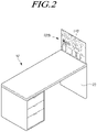
- FIGS. 1 and 2 are schematic views illustrating a display device according to embodiments of the present disclosure.
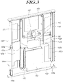
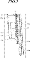
- FIGS. 3 to 5 are perspective views illustrating a display device according to embodiments of the present disclosure.
- FIG. 6 is a front view illustrating a display device according to embodiments of the present disclosure.
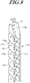
- FIGS. 7 to 9 are perspective views illustrating a display device according to embodiments of the present disclosure.
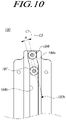
- FIG. 10 is an explanatory view illustrating an operating state of a display panel according to embodiments of the present disclosure.
- FIG. 11 is a perspective view illustrating a display device according to embodiments of the present disclosure.
- a display device may include a module housing 120 accommodating a display panel 110 pulled up and down, a moving plate 140 accommodated in the module housing 120 and pulled up and down with the display panel 110, the moving plate 140 has a front surface coupled to the display panel 110 and a rear surface provided with moving brackets 167a, 167b to which a driving belt 151 coupled, a driving member 150 pulling up and down the moving plate 140 by winding or releasing the driving belt 151, a fixed plate 130 coupled to the inside of the module housing 120 and to which the driving member 150 is fixed.
- Module housing 120 is built in and/or fixed inside of a main housing 10.
- the main housing 10 may be common furniture, equipment, facilities, etc.
- a display device wherein the module housing 120 is built in inside of a bottom support portion 20, corresponding to a leg of a table that is the most common furniture.
- the display panel 110 displays while the display panel 110 is pulled up to the upper portion of the table or pulled down from the upper portion of the table.
- a display device may provide either of an always-on-display mode (AOD mode), that continuously displays information such as a clock, weather or news, and a normal mode that displays an image or video intended by a user.
- AOD mode always-on-display mode
- a normal mode that displays an image or video intended by a user.
- the always-on-display mode 100a may be provided.
- FIG. 1 is illustrated, wherein the module housing 120 is installed by forming an empty space inside of the bottom support portion 20 of the main housing 10 when the always-on-display mode 100a is being provided.
- FIG. 2 is illustrated, wherein the normal mode 100b is being provided, which hold the display screen to the full size as the display panel 110 is pulled up.
- Module housing 120 has a rectangular shape in which the display panel 110, the moving plate 140, the driving member 150 and the fixed plate 130 are accommodated.
- the module housing 120 is partially omitted in the drawings for convenience of description.
- the display panel 110, the moving plate 140, and the fixed plate 130 to which the driving member 150 is coupled are accommodated in the module housing 120 and/or sequentially stacked from the front side to the rear side of the module housing 120.
- the display panel 110 is coupled to the front surface of the moving plate 140 and pulled up and down with the moving plate 140.
- the display panel 110 may be either an LCD panel or a light emitting display panel.
- the display panel when the display panel is an LCD panel, the display panel may further include a backlight unit irradiating light onto the LCD panel, a lower polarization plate attached to a lower substrate, and an upper polarization plate attached to the front surface of an upper substrate.
- the specific configurations of the lower substrate and the upper substrate may vary according to driving modes of the LCD panel, for example, twisted nematic (TN) mode, vertical alignment (VA) mode, in plane switching (IPS) mode, and fringe field switching (FFS) mode.
- TN twisted nematic
- VA vertical alignment
- IPS in plane switching
- FFS fringe field switching
- the light emitting display panel may include a lower substrate with a plurality of light emitting cells formed in the areas each of which is defined by gate lines, data lines, and power (VDD) lines, and an upper substrate bonded to the lower substrate face to face. Drawings and a detailed description of the light emitting display panel are not provided herein.
- the display panel is not limited to any particular type in embodiments of the present disclosure.
- the display panel may be made up of a flexible substrate to be bendable in embodiments of the present disclosure. The following description is given irrespective of display panel types.
- the display panel 110 is coupled to the front surface of the moving plate 140, and the moving brackets 167a, 167b which is coupled to the driving belt 151 are provided in the rear surface of the moving plate 140.
- the moving plate 140 moves along guide bars 161a, 161b, to be described later, with the display panel 110 when the driving belt 151 is being wound or released by the moving member 150.
- the moving bracket 167a, 167b are provided with a through hole 108, a flexible circuit film 106 connected to a source printed circuit board 102 of the display panel 110 is penetrated by the through hole 108.
- the display panel 110 and the moving plate 140 may be stably pulled up and down while the flexible circuit film 106 is connected to the control printed circuit board 105.
- the moving brackets 167a, 167b are fixed to the opposite side of the moving plate 140.
- the moving brackets 167a, 167b are fixed to one end 151a and other end 151b of the driving belt 151, respectively, and pulled up and down with the moving plate 140.
- the control printed circuit board 105 connected to the flexible circuit film 106 which is bent and passes through the through hole 108 is fixed to the rear surface of the one of the moving brackets 167a, 167b, for example, the moving bracket 167a.
- the control printed circuit board 105 connected to a main board 101 and/or a power board, to be described later may be stably fixed when the moving plate 140 and the display panel 110 are pulled up and down.
- a main board 110 on which an image processor electrically connected to the control printed circuit board 105 and supplying a data signal and/or a control signal is mounted, and/or a power board 103, which supplies power to the display panel 110, are fixed to the fixed plate 130, which is disposed at the rear to the moving plate 140.
- a position sensor 115 coupled to the fixed plate 130 senses and transmits the position of the display panel 110 to the main board 101.
- the main board 101 controls the display panel 110 to either of the always-on-display mode and the normal mode according to the position of the display panel 110.
- the position of the display panel 110 which determines the display panel 110 to the always-on-display mode may be set in advance. As illustrated in FIG. 1 , embodiments of the present disclosure may be provided with the main board 101 controlling the display panel 110 as the always-on-display mode when the display panel 110 is pulled up to the preset position of the upper portion of the table, by the way of example.
- the cable penetrating member 170 includes one end 170b coupled to the fixed plate 130 and other end 170a coupled to the moving bracket 167a of the moving plate 140. Thus, the other end 170a of the cable penetrating member 170 is pulled up and down with the moving plate 140.
- the cable penetrating member 170 includes a plurality of connecting members 173 rotatably connected to each other. Each of the connecting members has an empty space formed therein so that the cables 101a, 103a may penetrate from the one end 170b to the other end 170a of the cable penetrating member 170.
- the cable penetrating member 170 maintains "U" shape, the lengths of both sides of which change when the moving plate 140 is being pulled up and down, thereby preventing the cables 101a, 103a from interference with surrounding electronic components while being pulled up and down.
- Each of the connecting members 173 has a couple of first connecting portions 175 disposed opposite to each other and a couple of second connecting portions 177 disposed opposite to each other.
- the first connecting portions 175 are extended in one direction from a center portion provided with the empty space through which the cables 101a, 103a pass.
- the second connecting portions 177 are extended in the opposite direction from the center portion.
- the first connecting portions 175 are provided with connecting holes 175a and are overlapped with the second connecting portions 177 of the nearby connecting member 173.
- the first connecting portion 175 and the second connecting portion 177 adjacent to each other are coupled as a rotation protrusion 177a is inserted to the connecting hole 175a.
- the connecting member 173 disposed at the one end 170b and the other end 170a of the cable penetrating member 170 are provided with a coupling hole 171 so as to be coupled to the fixed plate 130 and the moving bracket 167a by a coupling member.
- the driving member 150 pulling up and down the moving plate 140 includes, a driving motor 157 coupled to the fixed plate 130, a driving gear 156 and a driven gear 154 rotated by the driving motor 157, a driving pulley 153 coupled coaxially to the driven gear 154 to wind or release the driving belt 151, and driven pulleys 155a, 155b connected to the driving pulley 153 by the driving belt 151 and coupled to the fixed plate 130.
- the driving motor 157 rotates the driving pulley 153 with the number of revolutions reduced by the constant gear ratio between the driving gear 156 and the driven gear 154.
- the opposite ends of the driving belt 151 are coupled to the driving pulley 153 to be wound in the same direction.
- the moving plate 140 and the display panel 110 are pulled up when the driving belt 151 is wound as the driving pulley 153 rotates in one direction, and the moving plate 140 and the display panel 110 are pulled down when the driving belt 151 is released as the driving pulley 153 rotates in opposite direction.
- the driving member 150 may further includes guide bars 161a, 161b each including opposite ends fixed to the module housing 120, and moving guides 165a, 165b coupled to one side of the moving plate 140 and pulled up and down along the guide bars 161a, 161b.
- the moving guide 165a, 165b coupled to the moving plate 140 are pulled up and down along the guide bars 161a, 161b.
- the moving plate 140 is stably pulled up and down without being biased to either side while the driving force of the driving motor 157 pulls up and down the moving plate 140 via the driving belt 151.
- the guide bars 161a, 161b and/or the moving guides 165a, 165b are disposed at the opposite sides of the module housing 120 and guide the moving plate 140 to be pulled up and down. Stoppers 163a, 163b are provided nearby the middle of the guide bars 161a, 161b, respectively, to limit the height of the moving guides 165a, 165.
- FIG. 4 illustrates the moving plate 140 is being pulled up from the pulled down position 140a to the pulled up position 140b.
- FIG. 6 illustrates the display panel 110 at the pulled up position 140b.
- the driving member 150 may further includes elastic belts 181, having one end 181a coupled to the moving guide 165a, 165b and other end 181b fixed to the module housing 120, and belt rollers 183 fixed to the fixed plate 130 and the elastic belts 181 are wound on the belt rollers 183 and rotatably supported by the belt rollers 183.
- the elastic belts 181 are configured to provide a tensile force to the moving plate 140 at the pulled down position.
- the driving force of the driving motor 157 is assisted by the tensile force of the elastic belts 181 when the moving plate is being pulled up.
- a sliding door 180 which is closed when the display panel 110 is drawn in and is opened when the display panel 110 is drawn out by being slid in the front and rear directions of the module housing 120 to pull up the display panel 110 is provided at the upper portion of the module housing 120.
- the display panel 110 may not be exposed outside or may be in the always-on-display mode illustrated in FIG. 1 .
- the sliding door 180 is opened by being slid in the front and rear directions of the module housing 120.
- Door levers 191 each includes one end coupled to the sliding door 180 and other end rotatably coupled to the fixed plate 130 are provided.
- Each of the door levers 191 is rotatably coupled to a hinge bracket 133 coupled to the fixed plate 130 via a hinge axis 190h, and is supported by a sliding rail 190 coupled to the moving plate 140 by a rotation supporting member 197 provided at a support hole 193 of the door lever 191 spaced apart from the hinge axis 190h.
- the sliding rail 190 at two sides of the moving plate 140 are the sliding rail 190a and the sliding rail 190b respectively.
- the rotation supporting member 197 may be a roller or a bearing.
- the rotation supporting shaft 195 is rotatably coupled to the support hole 193.
- a guide groove 194 into which the rotation supporting member 197 is inserted is provided inside of the sliding rail 190.
- the guide groove 194 includes a top guide groove 194t and a bottom guide groove 194b having parallel center lines C1, C2 and connected via a curved groove 194s.
- the center line C1 of the top guide groove 194t and the center line C2 of the bottom guide groove 194b are disposed parallel with a constant distance.
- the rotation supporting member 197 inserted into the guide groove 194 is provided at the opposite sides of the top guide groove 194t or the opposite sides of the bottom guide groove 194b.
- the rotation supporting member 197 moves along the top guide groove 194t, the curved groove 194s, and the bottom guide groove 194b when the sliding rail 190 is pulled up and down with the moving plate 140.
- the door lever 191 is rotated with a predetermined angle A about the hinge shaft 190h as the rotation support member 197 moves, so that the sliding door 180 is opened or closed.
- a door plate 183 provided with a moving hole 185 configured to enable the door lever 191 to move is coupled to the module housing 120 beneath the sliding door 180.
- a door guide 187 guiding the sliding door 180 is coupled to the sliding door 180 and moves along a coupling hole of the door plate 183.
- the display panel 110 is protected from an external impact and occupies minimized space as the sliding door 180 closed the upper portion of the module housing 120 when accommodating the display panel 110 into the main housing 10 so as not to be exposed outside.
- a display device allowing a user to freely accommodate a display panel in a housing so as not to be externally exposed, or to change the display device between an always-on-display mode and a normal mode when the user needs.
- a display device configured to be mounted without being constrained by an additional mounting space, thereby using a space efficiently, and to reduce a risk of damage due to an external impact by minimizing the external exposure of the display panel, thereby satisfying various user demands.
Landscapes
- Engineering & Computer Science (AREA)
- Theoretical Computer Science (AREA)
- Physics & Mathematics (AREA)
- General Physics & Mathematics (AREA)
- Microelectronics & Electronic Packaging (AREA)
- General Engineering & Computer Science (AREA)
- Power Engineering (AREA)
- Computer Hardware Design (AREA)
- Mechanical Engineering (AREA)
- Devices For Indicating Variable Information By Combining Individual Elements (AREA)
- Tables And Desks Characterized By Structural Shape (AREA)
- Insertion, Bundling And Securing Of Wires For Electric Apparatuses (AREA)
- Casings For Electric Apparatus (AREA)
- Fittings On The Vehicle Exterior For Carrying Loads, And Devices For Holding Or Mounting Articles (AREA)
Abstract
Description
- This application claims priority from
Korean Patent Application No. 10-2020-0171610, filed on December 09, 2020 - Embodiments of the present disclosure relate to a display device.
- In general, liquid crystal display (LCD) devices, plasma display devices, field emission display devices, and light emitting display devices are under active research as flat display devices. Among them, the LCD devices and the light emitting display devices have attracted attention in view of their benefits of mass production, ease of driving means, and high image quality.
- However, such a display device has gradually increased in volume to meet the needs of users for a larger screen, thereby increasing a risk of damage to the display panel and requiring a larger space for installation which makes users difficult to secure the space.
- In addition, in order to provide an always-on-display mode that continuously displays various information desired by the users, an always-on-display device is required in addition to a general display device in a normal mode, which makes it difficult to satisfy various users demand.
- Therefore, to solve aforementioned problems and provide a display device which appeals more diverse use to users, there is a need for research on providing a display device engaged to furniture, equipment, facilities, etc., to implement various forms of display.
- Embodiments of the present disclosure provide a display device allowing a user to freely accommodate a display panel in a housing so as not to be externally exposed, or to change the display device between an always-on-display mode and a normal mode when the user needs.
- Embodiments of the present disclosure also provide a display device configured to be mounted without being constrained by an additional mounting space, thereby using a space efficiently, and to reduce a risk of damage due to an external impact by minimizing the external exposure of the display panel, thereby satisfying various user demands.
- The objectives of the embodiments of the present disclosure are not limited to what has been described above, and other unmentioned objectives will be clearly understood to those skilled in the art from the following description. The objects are achieved by the invention set out by the subject-matter of the independent claim(s).
- In a first aspect of the present disclosure is provided a display device including a module housing accommodating a display panel pulled up and down, a moving plate accommodated in the module housing and pulled up and down with the display panel, a driving member pulling up and down the moving plate and the display panel, a fixed plate coupled to the inside of the module housing and to which the driving member is fixed.
- According to embodiments of the present disclosure, there may be provided a display device allowing a user to freely accommodate a display panel in a housing so as not to be externally exposed, or to change the display device between an always-on-display mode and a normal mode when the user needs.
- According to embodiments of the present disclosure, there may be provided a display device configured to be mounted without being constrained by an additional mounting space, thereby using a space efficiently, and to reduce a risk of damage due to an external impact by minimizing the external exposure of the display panel, thereby satisfying various user demands.
- In a second aspect of the present technique a display device is provided. The display device includes: a module housing accommodating a display panel pulled up and down; a moving plate accommodated in the module housing and pulled up and down with the display panel, the moving plate has a front surface coupled to the display panel and a rear surface provided with moving brackets to which a driving belt coupled; a driving member pulling up and down the moving plate by winding or releasing the driving belt; and a fixed plate coupled to the inside of the module housing and to which the driving member is fixed.
- In a third aspect of the present technique a display device comprising: a module housing accommodating a display panel and having an opening for moving or drawing the display panel out from and/or into the module housing therethrough; a moving plate accommodated in the module housing, the moving plate having the display panel seated thereon and provided with one or more moving brackets, a driving belt coupled to the one or more moving bracket for moving or drawing the moving plate along with the display panel out from and into the module housing via the opening of the module housing, a driving member for moving or drawing the moving plate by winding or releasing the driving belt; and a fixed plate coupled to an inside of the module housing and having the driving member fixed thereon. Optionally, the display panel may be seated on a front surface of the moving plate and/or a rear surface of the moving plate may be provided with the one or more moving brackets.
- In a fourth aspect of the present technique a system or arrangement is provided comprising a main housing and a display device of any one of the aforementioned first, second and third aspects of the present technique.
- The display device of any one of the aforementioned first, second and third aspects of the present technique, or the system or arrangement of the fourth aspect of the present technique may include one or more of the following features.
- The moving brackets may be provided with a through hole penetrated by a flexible circuit film connected to a source printed circuit board of the display panel.
- A control printed circuit board to which the flexible circuit film penetrating the through hole is bent and connected may be fixed to the moving brackets.
- A main board and/or a power board may be fixed to the fixed plate.
- An image processor electrically connected to the control printed circuit board and supplying a data signal and a control signal may be mounted on the main board.
- The power board may supply power to the display panel.
- A position sensor may be coupled to the fixed plate to sense and transmit the position of the display panel to the main board.
- The main board may control the display panel as an always-on-display mode when an end portion of the display panel is overlapped with a preset position.
- The display device may further comprise: a cable penetrating member including one end coupled to the fixed plate and other end coupled to the moving plate.
- A data cable connecting the main board and the control printed circuit board and/or a power cable connecting the power board and the control printed circuit board may penetrate the inside the cable penetrating member.
- The cable penetrating member may include a plurality of connecting members rotatably connected to each other.
- Each of the connecting members may have a couple of first connecting portions disposed opposite to each other and a couple of second connecting portions disposed opposite to each other.
- The first connecting portions may be extended in one direction from a center portion provided with an empty space through which the data cable and/or the power cable may pass.
- The second connecting portions may be extended in a direction opposite to the one direction from the center portion.
- The first connecting portions may be provided with connecting holes.
- The second connecting portions may be provided with rotation protrusions.
- The first connecting portions and the second connecting portions may be overlapped with each other.
- The first connecting portions and the second connecting portions are coupled when the rotation protrusions are inserted to the connecting holes.
- The connecting members disposed at one end and/or the other end of the cable penetrating member may be provided with coupling holes.
- The driving member may comprise a driving motor coupled to the fixed plate.
- The driving member may comprise a driving gear and/or a driven gear rotated by the driving motor.
- The driving member may comprise a driving pulley coupled coaxially to the driven gear to wind or release the driving belt,
The driving member may comprise driven pulleys connected to the driving pulley by the driving belt and coupled to the fixed plate. - The driving member may comprise guide bars each including opposite ends fixed to the module housing.
- The driving member may comprise moving guides coupled to one side of the moving plate and pulled up and down along the guide bars, respectively.
- The driving member may include elastic belts, having one end coupled to the moving guides and other end fixed to the module housing.
- The driving member may include belt rollers fixed to the fixed plate.
- The elastic belts may be wound on the belt rollers and rotatably supported by the belt rollers.
- A sliding door which is closed when the display panel is moved in or drawn in and is opened when the display panel is moved out or drawn out by being slid in the front and rear directions of the module housing may be provided at the upper portion of the module housing.
- The display device may comprise door levers each including one end coupled to the sliding door and other end rotatably coupled to the fixed plate.
- Each of the door levers may be rotatably coupled to a hinge bracket coupled to the fixed plate with a hinge axis and may be supported by a sliding rail coupled to the moving plate by a rotation supporting member provided at a support hole of the door lever spaced apart from the hinge axis.
- A guide groove into which the rotation supporting member is inserted may be provided inside of the sliding rail.
- The guide groove may include a top guides groove and a bottom guide groove having parallel center lines, spaced apart from each other, and connected via a curved groove.
- The module housing may be built in and fixed inside of a main housing.
- The display panel may be pulled up to the upper portion of the main housing or pulled down from the upper portion of the main housing.
- The display panel, the moving plate and/or the fixed plate may be sequentially stacked from a front side to a rear side of the module housing.
- At least one, and preferable each, of the one or more moving brackets, may comprises a through hole.
- One or more flexible electric components such as a wire or a flexible circuit film, etc may be penetratingly arranged with or pass through the through-hole.
- The flexible circuit film may pass through the through-hole and be connected to a source printed circuit board of the display panel.
- The display device may comprise a control printed circuit board fixed to the moving brackets. The flexible circuit film may penetrate the through hole and be connected to the control printed circuit board.
- The display device may comprises at least one of: a main board and a power board.
- The main board may be fixed to the fixed plate.
- An image processor electrically connected to the control printed circuit board to supply a data signal and/or a control signal to the display panel may be mounted on the main board.
- The power board may be fixed to the fixed plate.
- The power board may be configured to supply power to the display panel.
- In the present technique, 'fixed', 'coupled', 'connected', 'mounted' 'provided on' and related terms may be interchangeably used and may be understood as physically fixed, coupled, connected, etc. unless otherwise stated. When a component A is 'fixed' to/with/on/at, 'coupled' to/with/on/at, 'connected' to/with/on/at, 'mounted' to/with/on/at, 'provided' to/with/on/at another component B, then it means the two components A and B are connected to each other such that they remain at rest or move together as single unit/component/body, unless otherwise stated. In other words, the components A and B are disposed such that they are at rest or same relative position with respect to each other, at least at the mutual connection, unless otherwise stated. The components A and B can be any of the components of the display device of the aforementioned first, second and third aspects or arrangement/system of the aforementioned fourth aspect.
- The display device may include a position sensor.
- The position sensor may be coupled to the fixed plate and/or to the module housing and/or to the main housing.
- The position sensor is configured to sense a position of the display panel with respect to the module housing and/or with respect to the fixed plate and/or with respect to the main housing.
- The position sensor may transmit information relating to the position so sensed to the main board and/or to a controller.
- The main board or the controller may be configured to control the display panel in different modes - such as an 'always-on-display' mode and/or a 'normal' mode and/or 'off mode, based on the position of the display panel, for example as sensed by the position sensor, with respect to the module housing and/or with respect to the fixed plate and/or with respect to the main housing, for example based on a length of the display panel exposed outside or protruding out from/of the module housing and/or the main housing and/or the fixed plate and/or the opening of the module housing.
- In the 'always-on-display' mode, the display panel may be at a first position with respect to the module housing and/or with respect to the fixed plate and/or with respect to the main housing. The first position may correspond to a first protruded length and/or a first exposed area of the display panel (i.e. length or area available for viewing by a user) with respect to the module housing and/or with respect to the fixed plate and/or with respect to the main housing.
- In the 'normal' mode, the display panel may be at a second position with respect to the module housing and/or with respect to the fixed plate and/or with respect to the main housing. The second position may correspond to a second protruded length and/or a second exposed area of the display panel (i.e. length or area available for viewing by a user) with respect to the module housing and/or with respect to the fixed plate and/or with respect to the main housing.
- The second protruded length and/or the second exposed area of the display panel may be greater than the first protruded length and/or the first exposed area of the display panel.
- The 'off' mode of the display panel may be implemented based on express instruction of the user provided by a user interface, such as a remote, or may be implemented when the display panel is accommodated completely inside the module housing i.e. no area of the display panel is exposed outside the module housing.
- The display device may further comprise a cable penetrating member.
- The cable penetrating member may a flexible member within which at least a part of a cable such as signal line and/or power cable of the display device is arranged.
- The cable penetrating member may enclose at lease a part of the cable extending or running therethrough.
- The cable penetrating member may support the cable, i.e. a movement of the cable, when the display panel is drawn in and out, or moved in and out.
- The cable penetrating member may include one end coupled to the fixed plate and/or the module housing and another end coupled to the moving plate and/or the display panel. The other end may thus move along with the moving plate and/or the display panel when the moving plate is moved to be drawn in and out, or drawn in and out, of the module housing.
- The display device may comprise a data cable connecting the main board and the control printed circuit board, and/or a power cable connecting the power board and the control printed circuit board.
- The data cable and/or the power cable may run through an inside of the cable penetrating member, and may be moved with the cable penetrating member.
- The cable penetrating member may include a plurality of connecting members rotatably linked or connected to each other.
- Each connecting member defined a center portion having an empty space through which the cable supported by the cable penetrating member such as the data cable and/or the power cable passes.
- One or more, for example a couple of, first connecting portions may extend (or may be formed as extended or protruding or emanating) in one direction from the center portion. The couple of first connecting portion may be arranged opposite to each other or facing each other and the cable may run through the intervening gap or space.
- One or more, for example a couple of, second connecting portions may extend (or may be formed as extended or protruding or emanating) in a direction from the center portion different than or opposite the one direction. The couple of second connecting portion may be arranged opposite to each other or facing each other and the cable may run through the intervening gap or space.
- The first and the second connecting portions may be integrally formed with each other.
- The first connecting portions and the second connecting portions of adjacent connecting members may be rotatably interlinked. For example, the first connecting portion may be provided with a connecting hole, and the second connecting portion may be provided with a corresponding rotation protrusion to be inserted into the connecting hole of the adjacent connecting portion.
- The first connecting portion and the second connecting portion of adjacent connecting members may be arranged to partially overlapped with each other.
- The first connecting portion and the second connecting portion of adjacent connecting members may be coupled by the rotation protrusions inserted into the corresponding connecting hole.
- The connecting member, say a terminal connecting member, disposed at the one end of the cable penetrating member and/or the connecting member, say a terminal connecting member, disposed at the other end of the cable penetrating member may be provided with a coupling means for coupling the connecting member to the fixed plate and/or the moving bracket.
- The driving member may comprise a driving motor coupled to the fixed plate and/or to the module housing. The driving motor may provide force to move the movable plate relative to the fixed plate and/or relative to the module housing and/or relative to the main housing.
- The driving member may comprise a gear arrangement for example a driving gear and a driven gear. The gear arrangement may be driven by or rotated by the driving motor.
- The driving member may comprise a driving pulley coupled to the driven gear to wind or release/unwind the driving belt.
- The driving member may comprise one or more driven pulleys connected to the driving pulley by the driving belt and coupled to the fixed plate and/or to the module housing.
- The driving member may further comprise one or more guide bars fixed to the module housing and/or to the fixed plate; and one or more moving guides coupled to the moving plate and configured to move along the one or more guide bars, respectively.
- The one or more guide bars may guide the movement, e.g. translational movement, of the moving guides. The one or more moving guides may move along the guide bar.
- At least a part of the guide bar may be received in the moving guide, and the moving guide may slide along the guide bar.
- The driving member may include one or more elastic members such as one or more elastic belts.
- Each elastic member or belt may have one end coupled to the one or more moving guides and/or to the moving plate, and other end (i.e. an opposite end) fixed to the module housing and/or to the fixed plate.
- The elastic member may be tensioned by the movement of the moving plate relative to the module housing and/or to the fixed plate, for example when the moving plate is moved to be drawn into the module housing.
- The elastic member or belt may provide a pull on the moving guide and/or the moving plate, when the moving plate is moved to be drawn out of the module housing.
- One or more belt rollers may be fixed to the fixed plate and/or the module housing to support movement or elastic movement (tensioning/stretching and relaxing) of the elastic member or belt, during movement of the moving plate while being moved out or drawn out of and/or moved into or drawn into the module housing.
- The belt rollers may roll or rotate and thus allow the movement or elastic movement (tensioning/stretching and relaxing) of the elastic member or belt while supporting the elastic member or belt.
- The display device may include a door for covering i.e. opening and closing of the opening of the module housing.
- The door may be hinged at the opening of the module housing and may rotate about the axis of the hinge to open and close the opening of the module housing.
- The door may be hinged at a rear side of the module housing, i.e. a side at rear or non display side/face of the display panel, such that the door when opened is at a rear of the display panel, and thus out of the view of a viewer.
- The door may be a sliding door.
- The sliding door may be provided at the opening of the module housing.
- The sliding door may be configured to close the opening of the module housing when the display panel is moved into or drawn into the module housing, and/or to open the opening of the module housing when the display panel is moved out or drawn out of the module housing, by being slid in a front and rear direction of the module housing.
- The sliding door when opened may be at a rear of the display panel, and thus out of the view of a viewer. The sliding door may be at rear or at front of the display panel when opened.
- The display device may further comprise one or more door levers, each including one end coupled to the sliding door and other end rotatably coupled to the fixed plate and/or to the module housing.
- The display device may further comprising one or more hinge brackets coupled to the fixed plate and/or to the module housing.
- Each of the door levers may be rotatably coupled to the hinge bracket and may be rotatable about a hinge axis.
- Each of the door levers may include a support hole. A rotation supporting member may be provided at the support hole.
- The display device may comprise a sliding rail coupled to the moving plate, and configured to support a rotational movement of the rotation supporting member of the door levers.
- The sliding rail may include a guide groove into which the rotation supporting member may be inserted.
- The rotation supporting member may move or rotate and/or locomote in the guide groove while being supported by the sliding rail, i.e. walls of the sliding rail defining the guide groove.
- The guide groove includes a top guide groove and a bottom guide groove having parallel center lines, i.e. the top guide groove and a bottom guide groove may be parallel to each other. The top guide groove and the bottom guide groove may be connected via a curved groove disposed thereinbetween or extending between the top guide groove and the bottom guide groove.
- The top guide groove, the curved groove, and the bottom guide groove may be serially arranged or end-to-end connected to each other to define the guide groove of the sliding rail.
- The rotation supporting member may move from the bottom guide groove to the curved guide groove and then to the top guide groove, sequentially, when the door or the sliding door of the opening of the module housing is opened or slid to be opened.
- The present application envisages an arrangement or a system comprising a main housing and the display device according to any one of the aforementioned first, second and third aspect.
- The main housing may be part of a furniture.
- The module housing may be built in and/or fixed inside and/or accommodated in and/or completely accommodated inside of the main housing.
- The display panel when moved or drawn out from or of the module housing is movable relative to the main housing and is consequently moved or drawn out from or of the main housing to be exposed to a viewer.
- The display panel, the moving plate and the fixed plate may be sequentially arranged or stacked from a front side to a rear side of the module housing, respectively.
- In the present technique any reference to 'front' side or end may be understood as a side or end toward which a display side (where images are displayed i.e. having an active area of the display) of the display panel faces, i.e. front side of a component is a side or end that faces the same direction as the display side of the display panel faces, for example when moved or drawn out of the module housing. Similarly, 'back' side or end may be understood as a side or end opposite to the front side, i.e. on flip side of the front side, toward which a non-display side of the display panel faces, for example when moved or drawn out of the module housing.
- The opening of the module housing through which the display panel and/or the moving plate is moved out or drawn out and moved in or drawn in may be positioned at an upper end or upper portion or top side/end of the display device.
- The upper portion/end or top side/end may be understood with respect to a vertical direction in a state in which the display device or the arrangement is installed to be used.
- The upper portion/end or top side/end may be understood with respect to a direction along which the display panel and/or the moving plate is moved or drawn out, or moved or drawn in with respect to the fixed plate and/or the module housing and/or the main housing. The upper portion/end or top side/end may be a lateral side or lateral end, and thus the display panel and/or the moving plate may optionally for example be moved or drawn out or moved or drawn in in non-vertical direction such as horizontal direction.
-
-
FIGS. 1 and2 are schematic views illustrating a display device according to embodiments of the present disclosure. -
FIGS. 3 to 5 are perspective views illustrating a display device according to embodiments of the present disclosure. -
FIG. 6 is a front view illustrating a display device according to embodiments of the present disclosure. -
FIGS. 7 to 9 are perspective views illustrating a display device according to embodiments of the present disclosure. -
FIG. 10 is an explanatory view illustrating an operating state of a display panel according to embodiments of the present disclosure. -
FIG. 11 is a perspective view illustrating a display device according to embodiments of the present disclosure. - In the following description of examples or embodiments of the present invention, reference will be made to the accompanying drawings in which it is shown by way of illustration specific examples or embodiments that can be implemented, and in which the same reference numerals and signs can be used to designate the same or like components even when they are shown in different accompanying drawings from one another. Further, in the following description of examples or embodiments of the present invention, detailed descriptions of well-known functions and components incorporated herein will be omitted when it is determined that the description may make the subject matter in some embodiments of the present invention rather unclear. The terms such as "including", "having", "containing", "constituting", "make up of', and "formed of' used herein are generally intended to allow other components to be added unless the terms are used with the term "only". As used herein, singular forms are intended to include plural forms unless the context clearly indicates otherwise.
- Terms, such as "first", "second", "A", "B", "(A)", or "(B)" may be used herein to describe elements of the present invention. Each of these terms is not used to define essence, order, sequence, or number of elements etc., but is used merely to distinguish the corresponding element from other elements.
- When it is mentioned that a first element "is connected or coupled to", "contacts or overlaps" etc. a second element, it should be interpreted that, not only can the first element "be directly connected or coupled to" or "directly contact or overlap" the second element, but a third element can also be "interposed" between the first and second elements, or the first and second elements can "be connected or coupled to", "contact or overlap", etc. each other via a fourth element. Here, the second element may be included in at least one of two or more elements that "are connected or coupled to", "contact or overlap", etc. each other.
- When time relative terms, such as "after", "subsequent to", "next", "before", and the like, are used to describe processes or operations of elements or configurations, or flows or steps in operating, processing, manufacturing methods, these terms may be used to describe non-consecutive or non-sequential processes or operations unless the term "directly" or "immediately" is used together.
- In addition, when any dimensions, relative sizes etc. are mentioned, it should be considered that numerical values for an elements or features, or corresponding information (e.g., level, range, etc.) include a tolerance or error range that may be caused by various factors (e.g., process factors, internal or external impact, noise, etc.) even when a relevant description is not specified. Further, the term "may" fully encompasses all the meanings of the term "can".
-
FIGS. 1 and2 are schematic views illustrating a display device according to embodiments of the present disclosure.FIGS. 3 to 5 are perspective views illustrating a display device according to embodiments of the present disclosure.FIG. 6 is a front view illustrating a display device according to embodiments of the present disclosure.FIGS. 7 to 9 are perspective views illustrating a display device according to embodiments of the present disclosure.FIG. 10 is an explanatory view illustrating an operating state of a display panel according to embodiments of the present disclosure.FIG. 11 is a perspective view illustrating a display device according to embodiments of the present disclosure. - Referring to
FIGS. 1 to 11 , a display device according to embodiment of the present disclosure may include amodule housing 120 accommodating adisplay panel 110 pulled up and down, a movingplate 140 accommodated in themodule housing 120 and pulled up and down with thedisplay panel 110, the movingplate 140 has a front surface coupled to thedisplay panel 110 and a rear surface provided with movingbrackets belt 151 coupled, a drivingmember 150 pulling up and down the movingplate 140 by winding or releasing the drivingbelt 151, afixed plate 130 coupled to the inside of themodule housing 120 and to which the drivingmember 150 is fixed. -
Module housing 120 is built in and/or fixed inside of amain housing 10. Themain housing 10 may be common furniture, equipment, facilities, etc. - Hereinafter, a display device according to embodiments of the present disclosure is given, wherein the
module housing 120 is built in inside of abottom support portion 20, corresponding to a leg of a table that is the most common furniture. Thedisplay panel 110 displays while thedisplay panel 110 is pulled up to the upper portion of the table or pulled down from the upper portion of the table. - In addition, a display device according to embodiments of the present disclosure may provide either of an always-on-display mode (AOD mode), that continuously displays information such as a clock, weather or news, and a normal mode that displays an image or video intended by a user.
- As illustrated in
FIG. 1 , in usual time, most of thedisplay panel 110 is covered inside the module housing 120as only a portion of thedisplay panel 110 is pulled up, and the always-on-display mode 100a may be provided. -
FIG. 1 is illustrated, wherein themodule housing 120 is installed by forming an empty space inside of thebottom support portion 20 of themain housing 10 when the always-on-display mode 100a is being provided. -
FIG. 2 is illustrated, wherein thenormal mode 100b is being provided, which hold the display screen to the full size as thedisplay panel 110 is pulled up. -
Module housing 120 has a rectangular shape in which thedisplay panel 110, the movingplate 140, the drivingmember 150 and the fixedplate 130 are accommodated. Themodule housing 120 is partially omitted in the drawings for convenience of description. - The
display panel 110, the movingplate 140, and the fixedplate 130 to which the drivingmember 150 is coupled are accommodated in themodule housing 120 and/or sequentially stacked from the front side to the rear side of themodule housing 120. - The
display panel 110 is coupled to the front surface of the movingplate 140 and pulled up and down with the movingplate 140. According to embodiments of the present disclosure, thedisplay panel 110 may be either an LCD panel or a light emitting display panel. - That is, when the display panel is an LCD panel, the display panel may further include a backlight unit irradiating light onto the LCD panel, a lower polarization plate attached to a lower substrate, and an upper polarization plate attached to the front surface of an upper substrate. The specific configurations of the lower substrate and the upper substrate may vary according to driving modes of the LCD panel, for example, twisted nematic (TN) mode, vertical alignment (VA) mode, in plane switching (IPS) mode, and fringe field switching (FFS) mode.
- Further, when the display panel is a light emitting display panel, the light emitting display panel may include a lower substrate with a plurality of light emitting cells formed in the areas each of which is defined by gate lines, data lines, and power (VDD) lines, and an upper substrate bonded to the lower substrate face to face. Drawings and a detailed description of the light emitting display panel are not provided herein.
- As described above, the display panel is not limited to any particular type in embodiments of the present disclosure. For example, the display panel may be made up of a flexible substrate to be bendable in embodiments of the present disclosure. The following description is given irrespective of display panel types.
- The
display panel 110 is coupled to the front surface of the movingplate 140, and the movingbrackets belt 151 are provided in the rear surface of the movingplate 140. The movingplate 140 moves alongguide bars display panel 110 when the drivingbelt 151 is being wound or released by the movingmember 150. - In addition, the moving
bracket hole 108, aflexible circuit film 106 connected to a source printedcircuit board 102 of thedisplay panel 110 is penetrated by the throughhole 108. Thus, thedisplay panel 110 and the movingplate 140 may be stably pulled up and down while theflexible circuit film 106 is connected to the control printedcircuit board 105. - The moving
brackets plate 140. The movingbrackets end 151a andother end 151b of the drivingbelt 151, respectively, and pulled up and down with the movingplate 140. - The control printed
circuit board 105 connected to theflexible circuit film 106 which is bent and passes through the throughhole 108 is fixed to the rear surface of the one of the movingbrackets bracket 167a. Thus, the control printedcircuit board 105 connected to amain board 101 and/or a power board, to be described later, may be stably fixed when the movingplate 140 and thedisplay panel 110 are pulled up and down. - A
main board 110, on which an image processor electrically connected to the control printedcircuit board 105 and supplying a data signal and/or a control signal is mounted, and/or apower board 103, which supplies power to thedisplay panel 110, are fixed to the fixedplate 130, which is disposed at the rear to the movingplate 140. - In addition, a
position sensor 115 coupled to the fixedplate 130 senses and transmits the position of thedisplay panel 110 to themain board 101. Themain board 101 controls thedisplay panel 110 to either of the always-on-display mode and the normal mode according to the position of thedisplay panel 110. - The position of the
display panel 110 which determines thedisplay panel 110 to the always-on-display mode may be set in advance. As illustrated inFIG. 1 , embodiments of the present disclosure may be provided with themain board 101 controlling thedisplay panel 110 as the always-on-display mode when thedisplay panel 110 is pulled up to the preset position of the upper portion of the table, by the way of example. - A
cable penetrating member 170 protecting adata cable 101a, which connects themain board 101 and the control printedcircuit board 105, and/or apower cable 103a, which connects thepower board 103 and the control printedcircuit board 105, is provided. - The
cable penetrating member 170 includes oneend 170b coupled to the fixedplate 130 andother end 170a coupled to the movingbracket 167a of the movingplate 140. Thus, theother end 170a of thecable penetrating member 170 is pulled up and down with the movingplate 140. - The
cable penetrating member 170 includes a plurality of connectingmembers 173 rotatably connected to each other. Each of the connecting members has an empty space formed therein so that thecables end 170b to theother end 170a of thecable penetrating member 170. Thus, thecable penetrating member 170 maintains "U" shape, the lengths of both sides of which change when the movingplate 140 is being pulled up and down, thereby preventing thecables - Each of the connecting
members 173 has a couple of first connectingportions 175 disposed opposite to each other and a couple of second connectingportions 177 disposed opposite to each other. The first connectingportions 175 are extended in one direction from a center portion provided with the empty space through which thecables portions 177 are extended in the opposite direction from the center portion. - The first connecting
portions 175 are provided with connectingholes 175a and are overlapped with the second connectingportions 177 of the nearby connectingmember 173. The first connectingportion 175 and the second connectingportion 177 adjacent to each other are coupled as arotation protrusion 177a is inserted to the connectinghole 175a. - The connecting
member 173 disposed at the oneend 170b and theother end 170a of thecable penetrating member 170 are provided with acoupling hole 171 so as to be coupled to the fixedplate 130 and the movingbracket 167a by a coupling member. - The driving
member 150 pulling up and down the movingplate 140 includes, a drivingmotor 157 coupled to the fixedplate 130, adriving gear 156 and a drivengear 154 rotated by the drivingmotor 157, a drivingpulley 153 coupled coaxially to the drivengear 154 to wind or release the drivingbelt 151, and drivenpulleys pulley 153 by the drivingbelt 151 and coupled to the fixedplate 130. - The driving
motor 157 rotates the drivingpulley 153 with the number of revolutions reduced by the constant gear ratio between the drivinggear 156 and the drivengear 154. The opposite ends of the drivingbelt 151 are coupled to the drivingpulley 153 to be wound in the same direction. - Therefore, the moving
plate 140 and thedisplay panel 110 are pulled up when the drivingbelt 151 is wound as the drivingpulley 153 rotates in one direction, and the movingplate 140 and thedisplay panel 110 are pulled down when the drivingbelt 151 is released as the drivingpulley 153 rotates in opposite direction. - That is, when the driving
pulley 153 rotates in a clockwise direction inFIG. 3 which illustrates the front direction of the fixedplate 130 or when the drivingpulley 153 rotates in a counterclockwise direction inFIG. 4 which illustrates the rear direction of the movingplate 140, the movingplate 140 and thedisplay panel 110 are pulled up. - In addition, the driving
member 150 may further includesguide bars module housing 120, and movingguides plate 140 and pulled up and down along theguide bars - The moving
guide plate 140 are pulled up and down along theguide bars plate 140 is stably pulled up and down without being biased to either side while the driving force of the drivingmotor 157 pulls up and down the movingplate 140 via the drivingbelt 151. - The guide bars 161a, 161b and/or the moving
guides module housing 120 and guide the movingplate 140 to be pulled up and down.Stoppers guide bars guides 165a, 165. -
FIG. 4 illustrates the movingplate 140 is being pulled up from the pulled downposition 140a to the pulled upposition 140b.FIG. 6 illustrates thedisplay panel 110 at the pulled upposition 140b. - In addition, the driving
member 150 may further includeselastic belts 181, having oneend 181a coupled to the movingguide other end 181b fixed to themodule housing 120, andbelt rollers 183 fixed to the fixedplate 130 and theelastic belts 181 are wound on thebelt rollers 183 and rotatably supported by thebelt rollers 183. - The
elastic belts 181 are configured to provide a tensile force to the movingplate 140 at the pulled down position. Thus, the driving force of the drivingmotor 157 is assisted by the tensile force of theelastic belts 181 when the moving plate is being pulled up. - Therefore, a force to pull up the moving
plate 140 is reduced when the movingplate 140 is being pulled up, and the movingplate 140 is maintained horizontally while being pulled up and down. - Meanwhile, a sliding
door 180 which is closed when thedisplay panel 110 is drawn in and is opened when thedisplay panel 110 is drawn out by being slid in the front and rear directions of themodule housing 120 to pull up thedisplay panel 110 is provided at the upper portion of themodule housing 120. Thus, thedisplay panel 110 may not be exposed outside or may be in the always-on-display mode illustrated inFIG. 1 . - The sliding
door 180 is opened by being slid in the front and rear directions of themodule housing 120. Door levers 191 each includes one end coupled to the slidingdoor 180 and other end rotatably coupled to the fixedplate 130 are provided. - Each of the door levers 191 is rotatably coupled to a
hinge bracket 133 coupled to the fixedplate 130 via ahinge axis 190h, and is supported by a slidingrail 190 coupled to the movingplate 140 by arotation supporting member 197 provided at asupport hole 193 of thedoor lever 191 spaced apart from thehinge axis 190h. Wherein, the slidingrail 190 at two sides of the movingplate 140 are the slidingrail 190a and the slidingrail 190b respectively. - The
rotation supporting member 197 may be a roller or a bearing. Therotation supporting shaft 195 is rotatably coupled to thesupport hole 193. - As illustrated in
FIG. 9 , aguide groove 194 into which therotation supporting member 197 is inserted is provided inside of the slidingrail 190. As illustrated inFIG. 10 , theguide groove 194 includes atop guide groove 194t and abottom guide groove 194b having parallel center lines C1, C2 and connected via acurved groove 194s. - The center line C1 of the
top guide groove 194t and the center line C2 of thebottom guide groove 194b are disposed parallel with a constant distance. Therotation supporting member 197 inserted into theguide groove 194 is provided at the opposite sides of thetop guide groove 194t or the opposite sides of thebottom guide groove 194b. - Therefore, the
rotation supporting member 197 moves along thetop guide groove 194t, thecurved groove 194s, and thebottom guide groove 194b when the slidingrail 190 is pulled up and down with the movingplate 140. Thedoor lever 191 is rotated with a predetermined angle A about thehinge shaft 190h as therotation support member 197 moves, so that the slidingdoor 180 is opened or closed. - As illustrated in
FIG. 11 , adoor plate 183 provided with a movinghole 185 configured to enable thedoor lever 191 to move is coupled to themodule housing 120 beneath the slidingdoor 180. Adoor guide 187 guiding the slidingdoor 180 is coupled to the slidingdoor 180 and moves along a coupling hole of thedoor plate 183. - Therefore, the
display panel 110 is protected from an external impact and occupies minimized space as the slidingdoor 180 closed the upper portion of themodule housing 120 when accommodating thedisplay panel 110 into themain housing 10 so as not to be exposed outside. - As described above, according to embodiments of the present disclosure, there may be provided a display device allowing a user to freely accommodate a display panel in a housing so as not to be externally exposed, or to change the display device between an always-on-display mode and a normal mode when the user needs.
- Further, according to embodiments of the present disclosure, there may be provided a display device configured to be mounted without being constrained by an additional mounting space, thereby using a space efficiently, and to reduce a risk of damage due to an external impact by minimizing the external exposure of the display panel, thereby satisfying various user demands.
- The above description has been presented to enable any person skilled in the art to make and use the technical idea of the present invention, and has been provided in the context of a particular application and its requirements. Various modifications, additions and substitutions to the described embodiments will be readily apparent to those skilled in the art, and the general principles defined herein may be applied to other embodiments and applications without departing from the scope of the present invention. The above description and the accompanying drawings provide an example of the technical idea of the present invention for illustrative purposes only. That is, the disclosed embodiments are intended to illustrate the scope of the technical idea of the present invention. Thus, the scope of the present invention is not limited to the embodiments shown, but is to be accorded the widest scope consistent with the claims. The scope of protection of the present invention should be construed based on the following claims.
Claims (15)
- A display device comprising:a module housing (120) accommodating a display panel (110) and having an opening for moving the display panel (110) out from and into the module housing (120) therethrough;a moving plate (140) accommodated in the module housing (120), the moving plate (140) having the display panel (110) seated thereon and provided with one or more moving brackets (167a, 167b);a driving belt (151) coupled to the one or more moving bracket (167a, 167b) for moving the moving plate (140) along with the display panel (110) out from and into the module housing (120) via the opening of the module housing (20);a driving member (150) for moving the moving plate (140) by winding or releasing the driving belt (151); anda fixed plate (130) coupled to an inside of the module housing (120) and having the driving member (150) fixed thereon.
- The display device according to claim 1, wherein at least one of the one or more moving brackets (167a, 167b) comprises a through hole (108), and the display device comprises a flexible circuit film (106) arranged penetrating the through hole (108); andwherein the flexible circuit film (106) is connected to a source printed circuit board (102) of the display panel (110); and/orwherein the display device comprises a control printed circuit board (105) fixed to the moving brackets (167a, 167b), and wherein the flexible circuit film (106) penetrating the through hole (108) is bent and connected to the control printed circuit board (105).
- The display device according to claim 2, wherein the display device comprises at least one of:a main board (101) fixed to the fixed plate (130), wherein the main board (101) is configured to supply a data signal and/or a control signal to the display panel (110) and is electrically connected to the control printed circuit board (105); anda power board (103) fixed to the fixed plate (130), wherein the power board (103) is configured to supply power to the display panel (110).
- The display device according to claim 3, comprising a position sensor (115) coupled to the fixed plate (130) and configured to sense and transmit a position of the display panel (110) with respect to the module housing (120) to the main board (101); and/or
wherein the main board (101) is configured to control the display panel (110) in an always-on-display mode and/or a normal mode, based on a length of the display panel (110) exposed outside the module housing (120). - The display device according to claim 3 or 4, wherein the display device further comprises:a cable penetrating member (170) including one end (170b) coupled to the fixed plate (130) and other end (170a) coupled to the moving plate (140) to move along with the moving plate (140); andwherein the display device comprises a data cable (101a) connecting the main board (101) and the control printed circuit board (105), and/or a power cable (103a) connecting the power board (103) and the control printed circuit board (105), andwherein the data cable (101a) and/or the power cable (103a) are run through an inside of the cable penetrating member (170).
- The display device according to claim 5, wherein the cable penetrating member (170) includes:
a plurality of connecting members (173) rotatably connected to each other, each connecting member (173) having:a center portion defining an empty space through which the data cable (101a) and/or the power cable (103a) pass;one or more first connecting portions (175) extended in one direction from the center portion; andone or more second connecting portions (177) extended in a direction opposite to the one direction from the center portion. - The display device according to claim 6,wherein the one or more first connecting portions (175) are provided with one or more connecting holes (175a), and the one or more second connecting portions (177) are provided with one or more rotation protrusions (177a), and wherein the one or more first connecting portions (175) and the one or more second connecting portions (177) are overlapped with each other and are coupled by the one or more rotation protrusions (177a) inserted into the one or more connecting holes (175a); and/orwherein the connecting member (173) disposed at the one end (170b) of the cable penetrating member (170) and/or the connecting member (173) disposed at the other end (170a) of the cable penetrating member (170) is provided with a coupling hole (171) to couple the connecting member (173) to the fixed plate (130) and/or the moving plate.
- The display device according to any one of the preceding claims, wherein the driving member (150) comprises:a driving motor (157) coupled to the fixed plate (130);a driving gear (156) and a driven gear (154) rotated by the driving motor (157);a driving pulley (153) coupled to the driven gear (154) to wind or release the driving belt (151); andone or more driven pulleys (155a, 155b) connected to the driving pulley (153) by the driving belt (151) and coupled to the fixed plate (130).
- The display device according to claim 8, wherein the driving member (150) further comprises:one or more guide bars (161a, 161b) fixed to the module housing (120); andone or more moving guides (165a, 165b) coupled to the moving plate (140) and configured to move along the one or more guide bars (161a, 161b), respectively.
- The display device according to claim 9, wherein the driving member (150) includes:one or more elastic belts (181), each having one end (181a) coupled to the one or more moving guides (165a, 165b) and other end (181b) fixed to the module housing (120); andone or more belt rollers (183) fixed to the fixed plate (130), and the one or more elastic belts (181) are rotatably supported by the one or more belt rollers (183).
- The display device according to any one of the preceding claims, comprising:
a sliding door (180) provided at the opening of the module housing (120) and configured to close the opening of the module housing (120) when the display panel (110) is moved into the module housing (120) and/or to open the opening of the module housing (120) when the display panel (110) is moved out of the module housing (120), by being slid in a front and rear direction of the module housing (120). - The display device according to claim 11, wherein the display device further comprises:
one or more door levers (191), each including one end coupled to the sliding door (180) and other end rotatably coupled to the fixed plate (130). - The display device according to claim 12, comprising one or more hinge brackets (133) coupled to the fixed plate (130), wherein each of the door levers (191) is rotatably coupled to the hinge bracket (133) and is rotatable about a hinge axis (190h); andwherein each of the door levers (191) includes a support hole (193), and a rotation supporting member (197) provided at the support hole (193); andwherein display device comprises a sliding rail (190) coupled to the moving plate (140) and configured to support a movement of the rotation supporting member (197) of the door levers (191).
- The display device according to claim 13, wherein a guide groove (194) into which the rotation supporting member (197) is inserted is provided inside of the sliding rail (190); or
wherein a guide groove (194) into which the rotation supporting member (197) is inserted is provided inside of the sliding rail (190), wherein the guide groove (194) includes a top guide groove (194t) and a bottom guide groove (194b) having parallel center lines (C1, C2), and wherein the top guide groove (194t) and the bottom guide groove (194b) are connected via a curved groove (194s) disposed thereinbetween. - An arrangement comprising a main housing (120) and the display device according to any one of the preceding claims, wherein the module housing (120) is built in and/or fixed to the main housing (20), and wherein the display panel (110) is movable relative to the main housing (20) by being moved out from and moved into the module housing (120); and/or
wherein the display panel (110), the moving plate (140) and the fixed plate (130) are sequentially stacked from a front side to a rear side of the module housing (120).
Applications Claiming Priority (1)
| Application Number | Priority Date | Filing Date | Title |
|---|---|---|---|
| KR1020200171610A KR102252766B1 (en) | 2020-12-09 | 2020-12-09 | Display device |
Publications (2)
| Publication Number | Publication Date |
|---|---|
| EP4012693A1 true EP4012693A1 (en) | 2022-06-15 |
| EP4012693B1 EP4012693B1 (en) | 2023-09-20 |
Family
ID=75915361
Family Applications (1)
| Application Number | Title | Priority Date | Filing Date |
|---|---|---|---|
| EP21209316.5A Active EP4012693B1 (en) | 2020-12-09 | 2021-11-19 | Display device |
Country Status (6)
| Country | Link |
|---|---|
| US (1) | US11527188B2 (en) |
| EP (1) | EP4012693B1 (en) |
| JP (1) | JP7291767B2 (en) |
| KR (1) | KR102252766B1 (en) |
| CN (1) | CN114613260B (en) |
| TW (1) | TWI793873B (en) |
Families Citing this family (11)
| Publication number | Priority date | Publication date | Assignee | Title |
|---|---|---|---|---|
| JP1685029S (en) * | 2020-07-21 | 2021-05-10 | ||
| TWD213105S (en) * | 2020-07-21 | 2021-08-01 | 南韓商樂金顯示科技股份有限公司 | Display device for furniture |
| KR102252777B1 (en) * | 2020-12-09 | 2021-05-14 | 엘지디스플레이 주식회사 | Display device |
| JP1718511S (en) * | 2021-01-08 | 2022-06-28 | TV screen | |
| CN115412622B (en) * | 2021-05-28 | 2026-03-20 | 北京小米移动软件有限公司 | Opening mechanism and electronic equipment |
| WO2023008600A1 (en) * | 2021-07-28 | 2023-02-02 | 엘지전자 주식회사 | Display device |
| US11927299B1 (en) * | 2021-08-23 | 2024-03-12 | Randy Embrey | Two display monitor mechanism |
| KR102891723B1 (en) * | 2021-12-02 | 2025-11-27 | 엘지디스플레이 주식회사 | Display device |
| KR102794987B1 (en) * | 2022-09-02 | 2025-04-15 | 엘지전자 주식회사 | Display device |
| KR102949478B1 (en) * | 2023-12-15 | 2026-04-06 | 서원대학교산학협력단 | smart class system using ESL tag |
| TWI893742B (en) * | 2024-04-02 | 2025-08-11 | 友達光電股份有限公司 | Display device |
Citations (4)
| Publication number | Priority date | Publication date | Assignee | Title |
|---|---|---|---|---|
| US7806490B1 (en) * | 2006-07-10 | 2010-10-05 | Importadvantage, Inc. | Panel mounted appliance elevator apparatus |
| KR20110000277U (en) * | 2009-07-03 | 2011-01-11 | 주식회사 일광산업 | LCD Monitor Installing Equipment with Automatic Opening Cover |
| WO2014114698A1 (en) * | 2013-01-23 | 2014-07-31 | Soltec D'enginyeria I Projectes, S.L. | Retractable screen device with autonomous, controlled speed lid opening |
| EP3367675A2 (en) * | 2016-01-21 | 2018-08-29 | Samsung Electronics Co., Ltd. | Image sound device having display portion that can appear/disappear |
Family Cites Families (34)
| Publication number | Priority date | Publication date | Assignee | Title |
|---|---|---|---|---|
| US3761152A (en) * | 1971-08-10 | 1973-09-25 | J Cory | Cabinet with elevator support platform |
| JPH0617150Y2 (en) * | 1989-06-15 | 1994-05-02 | 株式会社内田洋行 | Display lifting device for desk with built-in display |
| JP2851267B2 (en) * | 1996-08-09 | 1999-01-27 | パーク クワン−スー | Automatic lifting device for computer monitor box |
| US6190277B1 (en) * | 1997-07-10 | 2001-02-20 | Igus Spritzgussteile für die Industrie GmbH | Energy transmission chain |
| US20040090154A1 (en) * | 2002-11-13 | 2004-05-13 | Chun-Chung Chang | Lift for LCD |
| CN1514444A (en) * | 2002-12-31 | 2004-07-21 | 齐永仁 | Portable display screen frame |
| JP2008533503A (en) * | 2005-01-24 | 2008-08-21 | キルシュナー,ミッチェル | Thin screen storage device |
| KR100772635B1 (en) * | 2005-05-31 | 2007-11-02 | 한규동 | Display elevators and systems for tables |
| KR101148199B1 (en) * | 2005-07-05 | 2012-05-23 | 삼성전자주식회사 | Connector, Liquid Crystal Display Having The Same, And Method Of Engaging The Same |
| JP4607192B2 (en) * | 2006-01-06 | 2011-01-05 | シャープ株式会社 | Portable terminal device, display program, and recording medium |
| TWI552123B (en) * | 2009-01-28 | 2016-10-01 | 半導體能源研究所股份有限公司 | Display device |
| JP2010199672A (en) * | 2009-02-23 | 2010-09-09 | Funai Electric Co Ltd | Stand for flat screen tv |
| KR101620024B1 (en) * | 2009-02-27 | 2016-05-13 | 삼성디스플레이 주식회사 | Display apparatus and method of assembling the same |
| KR20110087357A (en) * | 2010-01-26 | 2011-08-03 | 심묘섭 | Cable Chain Structure |
| JP5032714B1 (en) * | 2011-03-28 | 2012-09-26 | 株式会社潤工社 | Cable support member |
| EP2607949B1 (en) * | 2011-12-23 | 2018-06-06 | Samsung Electronics Co., Ltd | Display module and display apparatus having the same |
| KR101573057B1 (en) * | 2014-06-23 | 2015-11-30 | 주식회사 비엔엘 | Screen is equipped with a video display device |
| KR101600925B1 (en) * | 2015-11-09 | 2016-03-08 | 주식회사 탑시스템 | A position control apparatus for a television receiver |
| KR102489588B1 (en) * | 2015-12-01 | 2023-01-17 | 엘지디스플레이 주식회사 | Liquid Crystal Display Device |
| CN206400973U (en) * | 2016-11-14 | 2017-08-11 | 广州视源电子科技股份有限公司 | Screen splicing component, screen splicing frame and spliced screen |
| KR102446200B1 (en) * | 2017-12-22 | 2022-09-21 | 엘지디스플레이 주식회사 | Flexible display device and rollable display device including same |
| KR102528883B1 (en) * | 2018-01-31 | 2023-05-08 | 엘지전자 주식회사 | Display device |
| KR102478444B1 (en) * | 2018-07-03 | 2022-12-15 | 엘지디스플레이 주식회사 | Display device |
| CN109099271A (en) * | 2018-08-23 | 2018-12-28 | 广州志昂机电设备有限公司 | The ultra-thin display band asynchronous double lifting video display terminals of microphone |
| KR20200031933A (en) * | 2018-09-17 | 2020-03-25 | 엘지디스플레이 주식회사 | Display device |
| CN208861603U (en) * | 2018-10-16 | 2019-05-14 | 深圳市维斯登光电有限公司 | A kind of multifunction electronic information display |
| DE112019001450B4 (en) * | 2018-11-09 | 2024-04-04 | Lg Electronics Inc. | Display device |
| TWI682267B (en) * | 2018-11-28 | 2020-01-11 | 和碩聯合科技股份有限公司 | Portable electrical device |
| KR102597411B1 (en) * | 2018-11-28 | 2023-11-01 | 엘지디스플레이 주식회사 | Display device |
| KR102544477B1 (en) * | 2019-01-07 | 2023-06-19 | 삼성전자주식회사 | An electronic device, a protecting case for the electronic device, and dispalying method thereof |
| CN209688413U (en) * | 2019-03-15 | 2019-11-26 | 商丘职业技术学院 | A kind of computer lifting display screen of motorized adjustment |
| CN110419865A (en) * | 2019-08-02 | 2019-11-08 | 徐州康泰家具有限公司 | A kind of Multifunctional desk |
| CN210896330U (en) * | 2019-09-25 | 2020-06-30 | 东莞市劲丰电子有限公司 | Chain-type flexible display extension auxiliary structure |
| CN111505851A (en) * | 2020-03-27 | 2020-08-07 | 深圳市晶泰液晶显示技术有限公司 | Liquid crystal display module |
-
2020
- 2020-12-09 KR KR1020200171610A patent/KR102252766B1/en active Active
-
2021
- 2021-11-19 EP EP21209316.5A patent/EP4012693B1/en active Active
- 2021-11-24 TW TW110143729A patent/TWI793873B/en active
- 2021-11-25 JP JP2021190690A patent/JP7291767B2/en active Active
- 2021-11-25 CN CN202111412418.XA patent/CN114613260B/en active Active
- 2021-12-01 US US17/539,920 patent/US11527188B2/en active Active
Patent Citations (4)
| Publication number | Priority date | Publication date | Assignee | Title |
|---|---|---|---|---|
| US7806490B1 (en) * | 2006-07-10 | 2010-10-05 | Importadvantage, Inc. | Panel mounted appliance elevator apparatus |
| KR20110000277U (en) * | 2009-07-03 | 2011-01-11 | 주식회사 일광산업 | LCD Monitor Installing Equipment with Automatic Opening Cover |
| WO2014114698A1 (en) * | 2013-01-23 | 2014-07-31 | Soltec D'enginyeria I Projectes, S.L. | Retractable screen device with autonomous, controlled speed lid opening |
| EP3367675A2 (en) * | 2016-01-21 | 2018-08-29 | Samsung Electronics Co., Ltd. | Image sound device having display portion that can appear/disappear |
Also Published As
| Publication number | Publication date |
|---|---|
| TW202223503A (en) | 2022-06-16 |
| US11527188B2 (en) | 2022-12-13 |
| TWI793873B (en) | 2023-02-21 |
| JP7291767B2 (en) | 2023-06-15 |
| KR102252766B1 (en) | 2021-05-14 |
| JP2022091695A (en) | 2022-06-21 |
| US20220180786A1 (en) | 2022-06-09 |
| CN114613260B (en) | 2024-01-19 |
| CN114613260A (en) | 2022-06-10 |
| EP4012693B1 (en) | 2023-09-20 |
Similar Documents
| Publication | Publication Date | Title |
|---|---|---|
| EP4012693B1 (en) | Display device | |
| EP4012490B1 (en) | Display device and driving device for display device | |
| US10642315B2 (en) | Display device | |
| US20220201883A1 (en) | Curvature variable display device | |
| EP3832629B1 (en) | Display device | |
| CN109074766B (en) | display device | |
| US11758671B2 (en) | Curvature variable display device | |
| CN106340254B (en) | Display device | |
| US11864334B2 (en) | Display device | |
| EP4012488B1 (en) | Flexible display device | |
| US11443660B2 (en) | Display device | |
| US20230217609A1 (en) | Display device | |
| US20230217611A1 (en) | Display device | |
| US12538441B2 (en) | Display device | |
| US12412489B2 (en) | Display device | |
| US12632084B2 (en) | Electronic apparatus |
Legal Events
| Date | Code | Title | Description |
|---|---|---|---|
| PUAI | Public reference made under article 153(3) epc to a published international application that has entered the european phase |
Free format text: ORIGINAL CODE: 0009012 |
|
| STAA | Information on the status of an ep patent application or granted ep patent |
Free format text: STATUS: REQUEST FOR EXAMINATION WAS MADE |
|
| 17P | Request for examination filed |
Effective date: 20211119 |
|
| AK | Designated contracting states |
Kind code of ref document: A1 Designated state(s): AL AT BE BG CH CY CZ DE DK EE ES FI FR GB GR HR HU IE IS IT LI LT LU LV MC MK MT NL NO PL PT RO RS SE SI SK SM TR |
|
| RBV | Designated contracting states (corrected) |
Designated state(s): AL AT BE BG CH CY CZ DE DK EE ES FI FR GB GR HR HU IE IS IT LI LT LU LV MC MK MT NL NO PL PT RO RS SE SI SK SM TR |
|
| GRAP | Despatch of communication of intention to grant a patent |
Free format text: ORIGINAL CODE: EPIDOSNIGR1 |
|
| STAA | Information on the status of an ep patent application or granted ep patent |
Free format text: STATUS: GRANT OF PATENT IS INTENDED |
|
| INTG | Intention to grant announced |
Effective date: 20230414 |
|
| GRAS | Grant fee paid |
Free format text: ORIGINAL CODE: EPIDOSNIGR3 |
|
| GRAA | (expected) grant |
Free format text: ORIGINAL CODE: 0009210 |
|
| STAA | Information on the status of an ep patent application or granted ep patent |
Free format text: STATUS: THE PATENT HAS BEEN GRANTED |
|
| AK | Designated contracting states |
Kind code of ref document: B1 Designated state(s): AL AT BE BG CH CY CZ DE DK EE ES FI FR GB GR HR HU IE IS IT LI LT LU LV MC MK MT NL NO PL PT RO RS SE SI SK SM TR |
|
| REG | Reference to a national code |
Ref country code: GB Ref legal event code: FG4D |
|
| REG | Reference to a national code |
Ref country code: CH Ref legal event code: EP |
|
| REG | Reference to a national code |
Ref country code: DE Ref legal event code: R096 Ref document number: 602021005270 Country of ref document: DE |
|
| REG | Reference to a national code |
Ref country code: IE Ref legal event code: FG4D |
|
| REG | Reference to a national code |
Ref country code: LT Ref legal event code: MG9D |
|
| PG25 | Lapsed in a contracting state [announced via postgrant information from national office to epo] |
Ref country code: GR Free format text: LAPSE BECAUSE OF FAILURE TO SUBMIT A TRANSLATION OF THE DESCRIPTION OR TO PAY THE FEE WITHIN THE PRESCRIBED TIME-LIMIT Effective date: 20231221 |
|
| REG | Reference to a national code |
Ref country code: NL Ref legal event code: MP Effective date: 20230920 |
|
| PG25 | Lapsed in a contracting state [announced via postgrant information from national office to epo] |
Ref country code: SE Free format text: LAPSE BECAUSE OF FAILURE TO SUBMIT A TRANSLATION OF THE DESCRIPTION OR TO PAY THE FEE WITHIN THE PRESCRIBED TIME-LIMIT Effective date: 20230920 Ref country code: RS Free format text: LAPSE BECAUSE OF FAILURE TO SUBMIT A TRANSLATION OF THE DESCRIPTION OR TO PAY THE FEE WITHIN THE PRESCRIBED TIME-LIMIT Effective date: 20230920 Ref country code: NO Free format text: LAPSE BECAUSE OF FAILURE TO SUBMIT A TRANSLATION OF THE DESCRIPTION OR TO PAY THE FEE WITHIN THE PRESCRIBED TIME-LIMIT Effective date: 20231220 Ref country code: LV Free format text: LAPSE BECAUSE OF FAILURE TO SUBMIT A TRANSLATION OF THE DESCRIPTION OR TO PAY THE FEE WITHIN THE PRESCRIBED TIME-LIMIT Effective date: 20230920 Ref country code: LT Free format text: LAPSE BECAUSE OF FAILURE TO SUBMIT A TRANSLATION OF THE DESCRIPTION OR TO PAY THE FEE WITHIN THE PRESCRIBED TIME-LIMIT Effective date: 20230920 Ref country code: HR Free format text: LAPSE BECAUSE OF FAILURE TO SUBMIT A TRANSLATION OF THE DESCRIPTION OR TO PAY THE FEE WITHIN THE PRESCRIBED TIME-LIMIT Effective date: 20230920 Ref country code: GR Free format text: LAPSE BECAUSE OF FAILURE TO SUBMIT A TRANSLATION OF THE DESCRIPTION OR TO PAY THE FEE WITHIN THE PRESCRIBED TIME-LIMIT Effective date: 20231221 Ref country code: FI Free format text: LAPSE BECAUSE OF FAILURE TO SUBMIT A TRANSLATION OF THE DESCRIPTION OR TO PAY THE FEE WITHIN THE PRESCRIBED TIME-LIMIT Effective date: 20230920 |
|
| REG | Reference to a national code |
Ref country code: AT Ref legal event code: MK05 Ref document number: 1614036 Country of ref document: AT Kind code of ref document: T Effective date: 20230920 |
|
| PG25 | Lapsed in a contracting state [announced via postgrant information from national office to epo] |
Ref country code: NL Free format text: LAPSE BECAUSE OF FAILURE TO SUBMIT A TRANSLATION OF THE DESCRIPTION OR TO PAY THE FEE WITHIN THE PRESCRIBED TIME-LIMIT Effective date: 20230920 |
|
| PG25 | Lapsed in a contracting state [announced via postgrant information from national office to epo] |
Ref country code: IS Free format text: LAPSE BECAUSE OF FAILURE TO SUBMIT A TRANSLATION OF THE DESCRIPTION OR TO PAY THE FEE WITHIN THE PRESCRIBED TIME-LIMIT Effective date: 20240120 |
|
| PG25 | Lapsed in a contracting state [announced via postgrant information from national office to epo] |
Ref country code: AT Free format text: LAPSE BECAUSE OF FAILURE TO SUBMIT A TRANSLATION OF THE DESCRIPTION OR TO PAY THE FEE WITHIN THE PRESCRIBED TIME-LIMIT Effective date: 20230920 |
|
| PG25 | Lapsed in a contracting state [announced via postgrant information from national office to epo] |
Ref country code: ES Free format text: LAPSE BECAUSE OF FAILURE TO SUBMIT A TRANSLATION OF THE DESCRIPTION OR TO PAY THE FEE WITHIN THE PRESCRIBED TIME-LIMIT Effective date: 20230920 |
|
| PG25 | Lapsed in a contracting state [announced via postgrant information from national office to epo] |
Ref country code: SM Free format text: LAPSE BECAUSE OF FAILURE TO SUBMIT A TRANSLATION OF THE DESCRIPTION OR TO PAY THE FEE WITHIN THE PRESCRIBED TIME-LIMIT Effective date: 20230920 Ref country code: RO Free format text: LAPSE BECAUSE OF FAILURE TO SUBMIT A TRANSLATION OF THE DESCRIPTION OR TO PAY THE FEE WITHIN THE PRESCRIBED TIME-LIMIT Effective date: 20230920 Ref country code: IS Free format text: LAPSE BECAUSE OF FAILURE TO SUBMIT A TRANSLATION OF THE DESCRIPTION OR TO PAY THE FEE WITHIN THE PRESCRIBED TIME-LIMIT Effective date: 20240120 Ref country code: ES Free format text: LAPSE BECAUSE OF FAILURE TO SUBMIT A TRANSLATION OF THE DESCRIPTION OR TO PAY THE FEE WITHIN THE PRESCRIBED TIME-LIMIT Effective date: 20230920 Ref country code: EE Free format text: LAPSE BECAUSE OF FAILURE TO SUBMIT A TRANSLATION OF THE DESCRIPTION OR TO PAY THE FEE WITHIN THE PRESCRIBED TIME-LIMIT Effective date: 20230920 Ref country code: CZ Free format text: LAPSE BECAUSE OF FAILURE TO SUBMIT A TRANSLATION OF THE DESCRIPTION OR TO PAY THE FEE WITHIN THE PRESCRIBED TIME-LIMIT Effective date: 20230920 Ref country code: AT Free format text: LAPSE BECAUSE OF FAILURE TO SUBMIT A TRANSLATION OF THE DESCRIPTION OR TO PAY THE FEE WITHIN THE PRESCRIBED TIME-LIMIT Effective date: 20230920 Ref country code: PT Free format text: LAPSE BECAUSE OF FAILURE TO SUBMIT A TRANSLATION OF THE DESCRIPTION OR TO PAY THE FEE WITHIN THE PRESCRIBED TIME-LIMIT Effective date: 20240122 Ref country code: SK Free format text: LAPSE BECAUSE OF FAILURE TO SUBMIT A TRANSLATION OF THE DESCRIPTION OR TO PAY THE FEE WITHIN THE PRESCRIBED TIME-LIMIT Effective date: 20230920 |
|
| PG25 | Lapsed in a contracting state [announced via postgrant information from national office to epo] |
Ref country code: PL Free format text: LAPSE BECAUSE OF FAILURE TO SUBMIT A TRANSLATION OF THE DESCRIPTION OR TO PAY THE FEE WITHIN THE PRESCRIBED TIME-LIMIT Effective date: 20230920 Ref country code: IT Free format text: LAPSE BECAUSE OF FAILURE TO SUBMIT A TRANSLATION OF THE DESCRIPTION OR TO PAY THE FEE WITHIN THE PRESCRIBED TIME-LIMIT Effective date: 20230920 |
|
| REG | Reference to a national code |
Ref country code: DE Ref legal event code: R097 Ref document number: 602021005270 Country of ref document: DE |
|
| PG25 | Lapsed in a contracting state [announced via postgrant information from national office to epo] |
Ref country code: MC Free format text: LAPSE BECAUSE OF FAILURE TO SUBMIT A TRANSLATION OF THE DESCRIPTION OR TO PAY THE FEE WITHIN THE PRESCRIBED TIME-LIMIT Effective date: 20230920 |
|
| PG25 | Lapsed in a contracting state [announced via postgrant information from national office to epo] |
Ref country code: DK Free format text: LAPSE BECAUSE OF FAILURE TO SUBMIT A TRANSLATION OF THE DESCRIPTION OR TO PAY THE FEE WITHIN THE PRESCRIBED TIME-LIMIT Effective date: 20230920 |
|
| PG25 | Lapsed in a contracting state [announced via postgrant information from national office to epo] |
Ref country code: LU Free format text: LAPSE BECAUSE OF NON-PAYMENT OF DUE FEES Effective date: 20231119 |
|
| PLBE | No opposition filed within time limit |
Free format text: ORIGINAL CODE: 0009261 |
|
| STAA | Information on the status of an ep patent application or granted ep patent |
Free format text: STATUS: NO OPPOSITION FILED WITHIN TIME LIMIT |
|
| PG25 | Lapsed in a contracting state [announced via postgrant information from national office to epo] |
Ref country code: MC Free format text: LAPSE BECAUSE OF FAILURE TO SUBMIT A TRANSLATION OF THE DESCRIPTION OR TO PAY THE FEE WITHIN THE PRESCRIBED TIME-LIMIT Effective date: 20230920 Ref country code: LU Free format text: LAPSE BECAUSE OF NON-PAYMENT OF DUE FEES Effective date: 20231119 Ref country code: DK Free format text: LAPSE BECAUSE OF FAILURE TO SUBMIT A TRANSLATION OF THE DESCRIPTION OR TO PAY THE FEE WITHIN THE PRESCRIBED TIME-LIMIT Effective date: 20230920 |
|
| REG | Reference to a national code |
Ref country code: BE Ref legal event code: MM Effective date: 20231130 |
|
| 26N | No opposition filed |
Effective date: 20240621 |
|
| REG | Reference to a national code |
Ref country code: IE Ref legal event code: MM4A |
|
| PG25 | Lapsed in a contracting state [announced via postgrant information from national office to epo] |
Ref country code: IE Free format text: LAPSE BECAUSE OF NON-PAYMENT OF DUE FEES Effective date: 20231119 |
|
| PG25 | Lapsed in a contracting state [announced via postgrant information from national office to epo] |
Ref country code: BE Free format text: LAPSE BECAUSE OF NON-PAYMENT OF DUE FEES Effective date: 20231130 |
|
| PG25 | Lapsed in a contracting state [announced via postgrant information from national office to epo] |
Ref country code: SI Free format text: LAPSE BECAUSE OF FAILURE TO SUBMIT A TRANSLATION OF THE DESCRIPTION OR TO PAY THE FEE WITHIN THE PRESCRIBED TIME-LIMIT Effective date: 20230920 |
|
| PG25 | Lapsed in a contracting state [announced via postgrant information from national office to epo] |
Ref country code: SI Free format text: LAPSE BECAUSE OF FAILURE TO SUBMIT A TRANSLATION OF THE DESCRIPTION OR TO PAY THE FEE WITHIN THE PRESCRIBED TIME-LIMIT Effective date: 20230920 Ref country code: IE Free format text: LAPSE BECAUSE OF NON-PAYMENT OF DUE FEES Effective date: 20231119 Ref country code: BE Free format text: LAPSE BECAUSE OF NON-PAYMENT OF DUE FEES Effective date: 20231130 |
|
| PG25 | Lapsed in a contracting state [announced via postgrant information from national office to epo] |
Ref country code: BG Free format text: LAPSE BECAUSE OF FAILURE TO SUBMIT A TRANSLATION OF THE DESCRIPTION OR TO PAY THE FEE WITHIN THE PRESCRIBED TIME-LIMIT Effective date: 20230920 |
|
| PG25 | Lapsed in a contracting state [announced via postgrant information from national office to epo] |
Ref country code: BG Free format text: LAPSE BECAUSE OF FAILURE TO SUBMIT A TRANSLATION OF THE DESCRIPTION OR TO PAY THE FEE WITHIN THE PRESCRIBED TIME-LIMIT Effective date: 20230920 |
|
| REG | Reference to a national code |
Ref country code: CH Ref legal event code: PL |
|
| REG | Reference to a national code |
Ref country code: CH Ref legal event code: PL |
|
| PG25 | Lapsed in a contracting state [announced via postgrant information from national office to epo] |
Ref country code: CH Free format text: LAPSE BECAUSE OF NON-PAYMENT OF DUE FEES Effective date: 20241130 |
|
| PG25 | Lapsed in a contracting state [announced via postgrant information from national office to epo] |
Ref country code: CY Free format text: LAPSE BECAUSE OF FAILURE TO SUBMIT A TRANSLATION OF THE DESCRIPTION OR TO PAY THE FEE WITHIN THE PRESCRIBED TIME-LIMIT; INVALID AB INITIO Effective date: 20211119 |
|
| PGFP | Annual fee paid to national office [announced via postgrant information from national office to epo] |
Ref country code: GB Payment date: 20250922 Year of fee payment: 5 |
|
| PGFP | Annual fee paid to national office [announced via postgrant information from national office to epo] |
Ref country code: FR Payment date: 20250925 Year of fee payment: 5 |
|
| PG25 | Lapsed in a contracting state [announced via postgrant information from national office to epo] |
Ref country code: TR Free format text: LAPSE BECAUSE OF FAILURE TO SUBMIT A TRANSLATION OF THE DESCRIPTION OR TO PAY THE FEE WITHIN THE PRESCRIBED TIME-LIMIT Effective date: 20230920 |
|
| PGFP | Annual fee paid to national office [announced via postgrant information from national office to epo] |
Ref country code: DE Payment date: 20250922 Year of fee payment: 5 |
|
| PG25 | Lapsed in a contracting state [announced via postgrant information from national office to epo] |
Ref country code: HU Free format text: LAPSE BECAUSE OF FAILURE TO SUBMIT A TRANSLATION OF THE DESCRIPTION OR TO PAY THE FEE WITHIN THE PRESCRIBED TIME-LIMIT; INVALID AB INITIO Effective date: 20211119 |