EP4012686A1 - Système et procédé permettant de réduire le temps d'occupation d'une piste au moyen d'un pseudo seuil - Google Patents
Système et procédé permettant de réduire le temps d'occupation d'une piste au moyen d'un pseudo seuil Download PDFInfo
- Publication number
- EP4012686A1 EP4012686A1 EP21212582.7A EP21212582A EP4012686A1 EP 4012686 A1 EP4012686 A1 EP 4012686A1 EP 21212582 A EP21212582 A EP 21212582A EP 4012686 A1 EP4012686 A1 EP 4012686A1
- Authority
- EP
- European Patent Office
- Prior art keywords
- runway
- pseudo
- aircraft
- glide path
- calculation module
- Prior art date
- Legal status (The legal status is an assumption and is not a legal conclusion. Google has not performed a legal analysis and makes no representation as to the accuracy of the status listed.)
- Pending
Links
Images


Classifications
-
- G—PHYSICS
- G08—SIGNALLING
- G08G—TRAFFIC CONTROL SYSTEMS
- G08G5/00—Traffic control systems for aircraft, e.g. air-traffic control [ATC]
- G08G5/0017—Arrangements for implementing traffic-related aircraft activities, e.g. arrangements for generating, displaying, acquiring or managing traffic information
- G08G5/0021—Arrangements for implementing traffic-related aircraft activities, e.g. arrangements for generating, displaying, acquiring or managing traffic information located in the aircraft
-
- G—PHYSICS
- G05—CONTROLLING; REGULATING
- G05D—SYSTEMS FOR CONTROLLING OR REGULATING NON-ELECTRIC VARIABLES
- G05D1/00—Control of position, course or altitude of land, water, air, or space vehicles, e.g. automatic pilot
- G05D1/04—Control of altitude or depth
- G05D1/06—Rate of change of altitude or depth
- G05D1/0607—Rate of change of altitude or depth specially adapted for aircraft
- G05D1/0653—Rate of change of altitude or depth specially adapted for aircraft during a phase of take-off or landing
- G05D1/0676—Rate of change of altitude or depth specially adapted for aircraft during a phase of take-off or landing specially adapted for landing
-
- G—PHYSICS
- G08—SIGNALLING
- G08G—TRAFFIC CONTROL SYSTEMS
- G08G5/00—Traffic control systems for aircraft, e.g. air-traffic control [ATC]
- G08G5/0004—Transmission of traffic-related information to or from an aircraft
- G08G5/0013—Transmission of traffic-related information to or from an aircraft with a ground station
-
- G—PHYSICS
- G08—SIGNALLING
- G08G—TRAFFIC CONTROL SYSTEMS
- G08G5/00—Traffic control systems for aircraft, e.g. air-traffic control [ATC]
- G08G5/02—Automatic approach or landing aids, i.e. systems in which flight data of incoming planes are processed to provide landing data
- G08G5/025—Navigation or guidance aids
Definitions
- Runways at airports are becoming increasingly more congested as the number of flights worldwide continues to increase.
- the increased congestion often results in increased delays for flights as there are a limited number of runways at airports, creating a bottleneck for takeoffs and landing.
- Air traffic controllers may try to alleviate runway congestion by decreasing the time between landings.
- decreasing the time between landings may increase risk of collision and/or damage due to wake turbulence from a preceding aircraft. Therefore, it would be advantageous to provide a solution that cures the shortcomings described above.
- the system includes a pseudo glide path calculation module.
- the pseudo glide path calculation module includes one or more processors.
- the pseudo glide path calculation module includes a memory communicatively coupled to the one or more processors and having instructions stored upon.
- the instructions when executed by the one or more processors, cause the one or more processors to receive coordinates for a runway, receive exit path coordinates for a runway, receive aircraft configuration data, receive aircraft status data, and receive runway environmental data.
- the instructions when executed by the one or more processors, cause the one or more processors to calculate a relative position of the aircraft in reference to the exit path coordinates and the runway environmental data.
- the instructions when executed by the one or more processors, cause the one or more processors to generate a pseudo displaced threshold for the runway. In some embodiments, the instructions, when executed by the one or more processors, cause the one or more processors to generate a pseudo approach glide path profile based on the pseudo displaced threshold.
- system further includes an aircraft status database configured to send aircraft configuration data to the pseudo glide path calculation module.
- system further includes a runway database configured to send at least one of the coordinates for the runway or the coordinates for the exit path of the runway to the pseudo glide path calculation module.
- the instructions stored upon the memory further include calculating at least one of an estimated runway occupation time or an actual runway occupation time.
- the system further includes a transmitter configured to transmit at least one of the estimated runway occupation time or the actual runway occupation time to an air traffic system.
- the runway environmental data comprises at least one of an estimated landing time, an estimated landing speed, or an estimated wake turbulence of a preceding aircraft landing on the runway.
- the pseudo displaced threshold is configured to include a margin of safety.
- system further includes a display configured to depict at least one of the pseudo displaced threshold or the pseudo approach glide path profile.
- the instructions stored upon the memory further include generating a go-around point.
- the approach pseudo glide path is configured to decrease runway occupation time.
- a pseudo glide path calculation module is disclosed.
- the pseudo glide path calculation module includes one or more processors.
- the pseudo glide path calculation module includes a memory communicatively coupled to the one or more processors and having instructions stored upon.
- the instructions when executed by the one or more processors, cause the one or more processors to receive coordinates for a runway, receive exit path coordinates for a runway, receive aircraft configuration data, receive aircraft status data, and receive runway environmental data. communicatively coupled to the one or more processors and having instructions stored upon.
- the instructions when executed by the one or more processors, cause the one or more processors to calculate a relative position of the aircraft in reference to the exit path coordinates and the runway environmental data. In some embodiments, the instructions, when executed by the one or more processors, cause the one or more processors to generate a pseudo displaced threshold for the runway. In some embodiments, the instructions, when executed by the one or more processors, cause the one or more processors to generate a pseudo approach glide path profile based on the pseudo displaced threshold.
- the instructions stored upon the memory further include calculating at least one of an estimated runway occupation time or an actual runway occupation time.
- the instructions stored upon the memory further include sending at least one of the estimated runway occupation time or the actual runway occupation time to an air traffic system to a transmitter configured to transmit at least one of the estimated runway occupation time or actual runway occupation time to the air traffic system.
- the runway environmental data includes at least one of an estimated landing time, and estimated landing speed, or an estimated wake turbulence of a preceding aircraft landing on the runway.
- the pseudo approach glide path profile is configured to include a margin of safety.
- the instructions stored upon the memory further include sending the pseudo approach glide path profile to a display configured to depict the pseudo approach glide path profile.
- a method to assist piloting of an aircraft in landing phase is also disclosed.
- the method includes receiving coordinates for a runway.
- the method includes receiving exit path coordinates for the runway.
- the method includes receiving aircraft status data.
- the method includes receiving runway environmental data.
- the method includes generating a pseudo displaced threshold for the runway via a pseudo glide path calculation module.
- the method includes calculating a relative position of the aircraft in reference to the exit path coordinates and the aircraft status data. On one or more embodiments of the method, the method includes generating a pseudo approach glide path profile based on the pseudo displaced threshold via the pseudo glide path calculation module.
- the method further includes generating at least one of an estimated runway occupation time or an actual runway occupation time via the pseudo glide path calculation module. In some embodiments of the method, the method includes transmitting the estimated runway occupation time or the actual runway occupation time.
- the runway environmental data includes at least one of an estimated landing time, and estimated landing speed, or an estimated wake turbulence of a preceding aircraft landing on the runway.
- the pseudo approach glide path profile is configured to include a margin of safety.
- a letter following a reference numeral is intended to reference an embodiment of the feature or element that may be similar, but not necessarily identical, to a previously described element or feature bearing the same reference numeral (e.g., 1, 1a, 1b).
- reference numeral e.g. 1, 1a, 1b
- Such shorthand notations are used for purposes of convenience only and should not be construed to limit the disclosure in any way unless expressly stated to the contrary.
- any reference to “one embodiment” or “some embodiments” means that a particular element, feature, structure, or characteristic described in connection with the embodiment is included in at least one embodiment disclosed herein.
- the appearances of the phrase “in some embodiments” in various places in the specification are not necessarily all referring to the same embodiment, and embodiments may include one or more of the features expressly described or inherently present herein, or any combination of sub-combination of two or more such features, along with any other features which may not necessarily be expressly described or inherently present in the instant disclosure.
- a system to assist piloting an aircraft in landing phase is disclosed.
- the system is configured to calculate a pseudo approach glide path profile for a landing aircraft.
- the system may increase the efficiency of runway usage in a safe manner.
- Aircraft are increasingly used for transport of people and cargo. As aircraft usage increases, the availability of airport runways often becomes a bottleneck, as runway building often does not increase with aircraft flight demand. Pilots and air traffic controllers often attempt to reduce runway congestion by reducing the time between landings at a particular runway. Reducing the time between landings can be dangerous, because an aircraft that attempts to land too close to a preceding aircraft risks crashing due to wake turbulence caused by the preceding aircraft.
- the system is configured to receive flight landing information for a specific runway (e.g., such as the status of the preceding landing, or an exit path the aircraft is instructed to take), and determine a pseudo displaced threshold point from which a pseudo approach glide path profile may be calculated. Once the pseudo approach glide path profile is calculated, the aircraft may follow the pseudo approach glide path profile to a safe landing that efficiently places the aircraft near an exit path.
- the system is configured to decrease runway occupation time, resulting in increased flights per runway per unit time and increased fuel savings due to decreased taxi time.
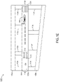
- FIG. 1A-E are diagrams illustrating a runway layout 100, in accordance with one or more embodiments of this disclosure.
- the runway layout includes a runway 104, one or more taxiways 108a-b and one or more exit paths 112a-h that link the runway 104 to the one or more taxiways 108a-b.
- the runway 104 may also include one or more markings.
- the runway may include one or more threshold markings 116a-b that define the runway threshold 122a-b (e.g., beginning or end) of the landing area of the runway. Instance, the length between two threshold markings 116a-b may define the space by which a landing may occur.
- the runway may include a displaced runway threshold 120 (e.g., as shown in FIG. 1B ).
- the displaced runway threshold 120 is a runway threshold 116 located at a point other than the physical beginning or end of the runway 104.
- the displaced threshold 120 is marked by displaced threshold markings 124.
- the displaced threshold markings 124 and the physical end of the runway 104 define a displaced portion 128 of the runway 104.
- the displaced portion 128 of the runway 104 is typically used for takeoff, but not for landing.
- the displaced portion 128 may be a section of the runway 104 that is no longer able to sustain the continuous impact from landing aircraft, but may still be operable for aircraft to initiate takeoff.
- the aircraft layout 100 includes a pseudo displaced threshold 132 as indicated by pseudo displaced threshold markings 134.
- the pseudo displaced threshold 132 is a virtualized threshold that is calculated by an aircraft for landing purposes.
- a pseudo displaced threshold 132 may be calculated in order to decrease the time that the aircraft is on the runway.
- the aircraft may calculate a pseudo displaced threshold 132 further down the runway 104, which increased the displaced portion 128 of the runway, and decreases the length of the used runway, and may decrease the time that the aircraft is on the runway, as the aircraft will turn off to the exit path 112h sooner than if the aircraft had initiated landing at the original runway threshold 122a.
- the pseudo displaced threshold is used to calculate a pseudo approach glide path profile 140 (e.g., as shown on FIG. 1D , along with a representative aircraft 144). Glid paths typically follow a 3° approach that is calculated to land at or near the runway threshold 116 or the displaced runway threshold 120. Once the pseudo displaced threshold is determined, the pseudo approach glide path profile 140 may then be calculated.
- the pseudo displaced threshold 132 may be calculated by an aircraft to ensure that the landing will not be affected by wake turbulence that has formed behind a preceding aircraft 146 (e.g., as shown in FIG. 146).
- Wake turbulence is a disturbance in the atmosphere that forms behind the preceding aircraft 146 as it passes through the air (e.g., during flight, takeoff, or landing) that can be hazardous to following aircraft.
- the pseudo displaced threshold 132 may be calculated by taking into account the characteristics of the preceding aircraft 146 (e.g., type of aircraft, known wake turbulence characteristics of the aircraft) and/or the assigned exit path 112a-h.
- FIG. 2 is a diagram illustrating a system 200 for determining the pseudo displaced threshold 132 and the pseudo approach glide path profile 140, in accordance with one or more embodiments of the disclosure.
- the system 200 includes a pseudo glide path calculation module 202 configured to calculate the pseudo displaced threshold 132 and the pseudo approach glide path profile 140.
- the pseudo glide path calculation module 202 may be configured as any type of module or part of a system.
- the pseudo glide path calculation module 202 may be configured as a module within a flight data processing system (e.g., flight management equipment or a system capable of processing flight data).
- the flight data processing system may also be configured as a flight management system.
- the flight data processing system may be configured to determine both the pseudo displaced threshold 132 and the pseudo approach glide path profile 140 via the pseudo glide path calculation module.
- the pseudo glide path calculation module 202 may be configured as a module within an instrument landing system.
- the pseudo glide path calculation module may be configured as a stand-alone module in an aircraft 144.
- the pseudo glide path calculation module 202 may be configured within an aircraft control system.
- the pseudo glide path calculation module 202 may be physically located at or near an air traffic control tower and configured to transmit the pseudo approach glide path profile to the aircraft 144.
- the pseudo glide path calculation module 202 may be configured as flight management equipment.
- the pseudo glide path calculation module 202 includes one or more controllers 204.
- the one or more controllers 204 control aspects of the systems and methods described herein.
- the one or more controllers 204 may include one or more processors 208, memory 212, and a communication interface 216.
- the memory 212 may store (e.g., have stored upon) one or more sets of program instructions.
- the one or more processors 208 may be configured to execute the one or more sets of program instructions to carry out one or more of the various steps or procedures described throughout the present disclosure.
- the system 200 may contain other componentry used to determine and report a pseudo approach glide path profile 140 that may or may not be considered part of the glide path calculation module 202. Therefore, the description herein should not be interpreted as a limitation of the present disclosure, but as an illustration.
- the system 200 includes a user interface 220 communicatively coupled to the one or more controllers 204 and configure to transmit information between the system and a user (e.g., the pilot of an aircraft).
- the user interface 220 may include any technology configured to assist interaction between the user and the system 200 including but not limited to keyboards, speakers, joysticks, and displays 224.
- the user interface 220 may be configured as any type of display 224 including but not limited to a synthetic vision system (SVS) display, an augmented reality (AR) display, a head up display (HUD), a multi-function display (MFD), or a virtual reality (VR display).
- SVS synthetic vision system
- AR augmented reality
- HUD head up display
- MFD multi-function display
- VR display virtual reality
- the system 200 may include a SVS display that overlays a predicted path on a virtual map of an airport layout.
- the display 224 may be configured as flight management equipment (e.g., such as a flight management system display, where the predicted path is overlaid on the display 224).
- the system 200 includes an aircraft status database 230 (e.g., configured as a server) communicatively coupled to the pseudo glide path calculation module 202 and configured to send aircraft status data to the pseudo glide path calculation module 202.
- the aircraft status data may include any type of information including but not limited to aircraft airspeed (e.g., indicated true airspeed, groundspeed, calibrated airspeed), aircraft velocity, aircraft position, outside temperature, outside wind speed), and aircraft configuration (e.g. aircraft weight, or aircraft type).
- the aircraft status database 230 may be disposed on board the aircraft 144.
- the aircraft status database 230 may be configured as a takeoff and landing (TOLD) database that is part of or communicatively coupled to the flight data processing system.
- the aircraft status database may be disposed within a base aircraft control system (e.g., data is sent wirelessly to the pseudo glide path calculation module 202).
- the system 200 includes a runway database 234 (e.g., configured as a server) that includes communicatively coupled to the pseudo glide path calculation module 202 and configured to send runway environmental data to the pseudo glide path calculation module 202.
- Runway environmental data may include any type of information including but not limited to runway dimension, runway slope, runway friction, weather conditions, runway surface conditions (e.g., ice, snow, or slush), presence or absence of the preceding aircraft 146, and the wake turbulence data relevant to a preceding aircraft 146.
- the runway database 234 may be disposed on board the aircraft 144.
- the runway database 234 may be configured as a navigation database (NavDB).
- NavDB navigation database
- the runway database 234 may be disposed within a base aircraft control system (e.g., data is sent wirelessly to the pseudo glide path calculation module 202). It should be understood that the aircraft status database 230 and the runway database 234 may combined as a single database, separated into multiple databases, or store different types of data. For example, the aircraft status database 230 may store airport weather data. Therefore, the above description should not be interpreted as a limitation of the present disclosure, but as an illustration.
- the system 200 includes a transmitter 238 configured to transmit data from the pseudo glide path calculation module 202.
- the transmitter 238 may transmit the data to any appropriate receiver, ground station, or communication system.
- the transmitter 238 may transmit data to Aeronautical Operational Control (AOC).
- the transmitter 238 may be configured to transmit landing data (e.g., pseudo displaced threshold and/or pseudo approach glide path profile data) to air traffic control (ATC).
- ATC air traffic control
- the transmitter 238 may be any transmitter 238 used for aircraft 144 to transmit aircraft communication to any appropriate receiver, station, or communication system.
- the pseudo glide path calculation module calculates the pseudo displaced threshold 132 based the instructed exit path, the presence or absence of a preceding aircraft 146, and data received from the aircraft status database 230 and the runway database 234. For example, when an instructed exit path 12h is transmitted to the aircraft, the pseudo glide path calculation module 202 calculates what length of runway would be required to safely land and brake so that the aircraft may safely turn onto the instructed exit path 12h.
- the calculation of the pseudo displaced threshold 132 may involve one or more of the data parameters discussed above (e.g., runway surface conditions).
- the pseudo glide calculation module 202 may be configured to include within the pseudo displaced threshold 132 a margin of safety.
- the margin of safety will allow a pilot to safely brake and turnoff the aircraft into the instructed exit path 12h, even if the aircraft touches down past the pseudo displaced threshold.
- the pseudo glide calculation module 202 may include a margin of safety within the pseudo displaced threshold 132 in a range of 10% to 30%.
- the pseudo glide calculation module may include a margin of safety within the pseudo displaced threshold 132 of 20%.
- the pseudo glide calculation module 202 may add a 20% margin of safety, or 200 meters, to the estimated required runway length needed for landing, and the pseudo displaced threshold 132 may be set at 1200 meters from the instructed exit path 112h.
- the margin of safety may also be described as a modification of a Pseudo Landing Run (PLR) calculation.
- TLR Total Landing Run
- PLR calc PLR distance
- BFE BFE*(PLR calc +(0.2* PLR calc )
- BFE is defined as a Brake Factor Error.
- BFE considers all or nearly all of the error defined in braking systems, which include but are not limited to factors such as: error due to differential braking, error due to differential speed of wheel as against speed of the aircraft, friction error due to various surface contaminants, and error due to excessive heat in the event of excessive breaking.
- BFE may configured at the software level.
- the BFE or one or more values used to calculate the BFE may also be acquired from original equipment manufacturers and/or auto braking system vendors.
- the pseudo glide path calculation module 202 calculates the pseudo approach glide path profile 140 based on pseudo displaced threshold 132 and other available data, including data received from the aircraft status database 230 and the runway database 234. For example, for a runway having a distance of 3000 meters between a runway threshold 122a and the instructed exit path 112h and having a distance of 1200 meters between a pseudo displaced threshold 132 and the instructed exit path 112h, the pseudo glide path calculation module 202 will calculate a pseudo approach glide path profile 140 based on the 1200-meter pseudo displaced threshold 132. The calculation of the pseudo approach glide path profile 140 may involve the pseudo displaced threshold 132 and one or more of the data parameters discussed above (e.g., aircraft velocity).
- the pseudo glide calculation module 202 may also be configured to determine a go-around point (e.g., a missed approach point). For example, the pseudo glide calculation module 202 may calculate a go-around point that, in the event the aircraft has not landed upon approaching the pseudo displaced threshold 132, will signal that the landing should be aborted and a go-around action be initiated.
- a go-around point e.g., a missed approach point
- the pseudo glide calculation module 202 is configure to determine an estimated runway occupation time (eROT) and/or an actual runway occupation time aROT.
- the eROT is the estimate time period that the aircraft 114 will be positioned on a runway 104 from initial touch down to exiting the runway 104 (e.g., via the instructed exit path 112h).
- the EOE may include one or more factor that adjusts the eROT based on predicted errors that may occur in the calculation of eROT.
- the EOE may include one or more factors that, when combined. adjust the eROT in a range of 1.0% to 5.0%. For instance, the EOE may adjust the eROT by 1.0%. In another example, the EOE may adjust the eROT by 5.0%. In another example, the EOE may adjust the eROT by 2.5%.
- a database may be prepared by acquiring data from one or more landing runs.
- This data table may include aircraft parameters data, aircraft configuration, runway data and environmental condition data (e.g., data from the aircraft status database 230 and/or the runway database 234) as well as landing data, such as average landing speed data and deceleration data.
- This data may be stored on the aircraft or a ground-based server (e.g., in the aircraft status database 230 in the runway database 234 or in a separate runway occupation time database).
- This database can be used to calculate the eROT. Once calculated, the ROT thus computed may be transmitted to any appropriate receiver, ground station, or communication system.
- the transmitter 238 may transmit the eROT to the ATC and/or AOC. Once transmitted, the ATC and/or AOC may use the eROT data to analyze runway usage and initiate changes that may safely increase runway efficiency and/or capacity.
- the aROT may be calculated by comparing the time of touchdown to the time of turnoff into the instructed exit path 112h.
- the aROT may be stored in the system 200 (e.g., in the aircraft status database 230 in the runway database 234 or in the separate runway occupation time database) and may be transmitted to ATC and/or AOC (e.g., via the transmitter 238). Once transmitted, the ATC and/or AOC may use the aROT data to analyze runway usage and initiate changes that may safely increase runway efficiency and/or capacity.
- the pseudo displaced threshold 132 and/or the pseudo approach glide path profile 140 are overlaid onto the display 224.
- the pseudo displaced threshold markings 134 may appear overlaid on the runway 144 (as in FIG. 1C-E ).
- the pseudo displaced threshold markings 134 may be depicted as yellow or some other indicative color on the SVS.
- the pseudo approach glide path profile 140 may appear overlaid on the runway 144 or a runway approach screen (as in FIG. 1D ).
- the pseudo approach glide path profile 140 may be depicted as yellow or some other indicative color on the SVS or on other systems, such as a runway awareness and advisory system (RAAS).
- RAAS runway awareness and advisory system
- one or more of the one or more controllers 204 are communicatively coupled (e.g., wirelessly and/or wireline) to other components of the system 200.
- one or more of the one or more controllers 204 may be communicatively coupled to the user interface 220 (e.g., the display 224), the aircraft status database 230, the runway database 234, and/or the transmitter 238.
- the one or more controllers 204 may also be communicatively coupled to other componentry within the within the system 200 that are not listed here. Therefore, the above description should not be interpreted as a limitation of the present disclosure, but as an illustration.
- the one or more processors 208 may include any one or more processing elements known in the art. In this sense, the one or more processors 208 may include any microprocessor device configured to execute algorithms and/or program instructions. In general, the term "processor" may be broadly defined to encompass any device having one or more processing elements, which execute a set of program instructions from a non-transitory memory medium (e.g., the memory 212), where the one or more sets of program instructions is configured to cause the one or more processors 208 to carry out any of one or more process steps.
- a non-transitory memory medium e.g., the memory 212
- the memory 212 may include any storage medium known in the art suitable for storing the one or more sets of program instructions executable by the associated one or more processors 208.
- the memory 212 may include a non-transitory memory medium.
- the memory 212 may include, but is not limited to, a read-only memory (ROM), a random-access memory (RAM), a magnetic or optical memory device (e.g., disk), a magnetic tape, a solid-state drive, and the like.
- the memory 212 may be configured to store user input information.
- the memory 212 may be housed in a common controller housing with the one or more processors 208.
- the memory 212 may, alternatively or in addition, be located remotely with respect to the spatial location of the processors 208, or the one or more controllers 204.
- the one or more processors 208 and/or one or more controllers 204 may access a remote memory 212 accessible through a network (e.g., wireless, and the like) via one or more communication interfaces 216.
- the one or more communication interfaces 216 may be operatively configured to communicate with components of the one or more controllers 204.
- the one or more communication interfaces 216 may be configured to retrieve data from the one or more processors 208 or other devices, transmit data for storage in the memory 212, retrieve data from storage in the memory 212, and so forth.
- the one or more communication interfaces 206 may also be communicatively coupled with the one or more processors 208 to facilitate data transfer between components of the one or more controllers 204 and the one or more processors 208.
- one or more communication interfaces 216 is described as a component of the one or more controllers 204, one or more components of the one or more communication interfaces 216 may be implemented as external components communicatively coupled to the one or more controllers 204 via a wired and/or wireless connection.
- the one or more controllers 204 may also include and/or connect to one or more user interfaces 220 (e.g., display 224).
- FIG. 3 is a block diagram illustrating a method 300 for determining the pseudo displaced threshold 132 and the pseudo approach glide path profile 140, in accordance with one or more embodiments of this disclosure.
- the method includes a step 302 of receiving coordinated for the runway 144.
- the pseudo glide path calculation module 202 may receive runway coordinates, or other runway information, from a runway database 234.
- the method 300 includes a step 304 of receiving exit path coordinated for the runway 144.
- the pseudo glide path calculation module 202 may receive exit path coordinates from the ATC or AOC (e.g., automatically or manually entered in via the user interface 220.
- the pseudo glide path calculation module 202 may receive exit path coordinates from the runway database 234.
- the method 300 includes a step 306 of receiving aircraft configuration data.
- the pseudo glide path calculation module 202 may receive aircraft configuration data in the form of aircraft braking ability or aircraft weight.
- the method 300 includes a step 308 of receiving aircraft status data.
- the pseudo glide path calculation module 202 may receive status data from the aircraft status database 230.
- the pseudo glide path calculation module 202 may receive aircraft velocity data from an aircraft status database 230 configured as any system or equipment capable of processing flight data( e.g., such as a flight management system)
- the pseudo glide path calculation module 202 may also receive aircraft configuration data from the aircraft status database (e.g., aircraft weight or braking characteristics).
- the method 300 includes a step 310 of receiving environmental data.
- the pseudo glide path calculation module 202 may receive current weather data for the runway.
- the pseudo glide path calculation module 202 may receive the data from either the aircraft status database 230 or the runway database 234.
- the method 300 includes a step 312 of generating a pseudo displaced threshold 132 for the runway via the pseudo glide path calculation module 202.
- the pseudo displaced threshold calculation may utilize aircraft configuration data, aircraft status data, and/or runway environmental data.
- the method 300 includes a step 314 of calculating the relative position of the aircraft 144 in reference to the exit path coordinates and the aircraft status data.
- the relative position of the aircraft 144 e.g., as determined by aircraft status data in the form of GPS coordinates and altimeter readings
- the relative position of the aircraft 144 may be calculated by the pseudo glide path calculation module 202.
- the method 300 includes a step 316 of generating the pseudo approach glide path profile 140 based on the displaced pseudo threshold via the pseudo glide path calculation module 202.
- the pseudo glide path calculation module 202 may utilize any aircraft configuration data, aircraft status data, runway environmental data along with runway coordinates to generate the pseudo approach glide path profile 140
- the method 300 includes a step 318 of generating at least one of an eROT or an aROT via the pseudo glide path calculation module. In some embodiments, the method includes a step of transmitting at least one of the eROT or aROT.
- the eROT and/or aROT may be transmitted to an ATC, an AOC, an aircraft database (e.g., a local server), or a separate ground-based server.
- embodiments of the methods disclosed herein may include one or more of the steps described herein. Further, such steps may be carried out in any desired order and two or more of the steps may be carried out simultaneously with one another. Two or more of the steps disclosed herein may be combined in a single step, and in some embodiments, one or more of the steps may be carried out as two or more sub-steps. Further, other steps or sub-steps may be carried in addition to, or as substitutes to one or more of the steps disclosed herein.
Applications Claiming Priority (2)
| Application Number | Priority Date | Filing Date | Title |
|---|---|---|---|
| IN202011053787 | 2020-12-10 | ||
| US17/217,011 US11817000B2 (en) | 2020-12-10 | 2021-03-30 | System and method to reduce runway occupancy time using pseudo threshold |
Publications (1)
| Publication Number | Publication Date |
|---|---|
| EP4012686A1 true EP4012686A1 (fr) | 2022-06-15 |
Family
ID=79185685
Family Applications (1)
| Application Number | Title | Priority Date | Filing Date |
|---|---|---|---|
| EP21212582.7A Pending EP4012686A1 (fr) | 2020-12-10 | 2021-12-06 | Système et procédé permettant de réduire le temps d'occupation d'une piste au moyen d'un pseudo seuil |
Country Status (1)
| Country | Link |
|---|---|
| EP (1) | EP4012686A1 (fr) |
Citations (5)
| Publication number | Priority date | Publication date | Assignee | Title |
|---|---|---|---|---|
| US20050006524A1 (en) * | 2003-07-08 | 2005-01-13 | Airbus France | System for aiding control of the deceleration of an aircraft moving over the ground |
| US20130278444A1 (en) * | 2012-04-24 | 2013-10-24 | Honeywell International Inc. | System and method of displaying a runway temporarily displaced threshold and an aircraft landing aiming point |
| US20150120098A1 (en) * | 2013-10-28 | 2015-04-30 | The Boeing Company | Aircraft Stopping Performance Display and Warning |
| US20170129623A1 (en) * | 2015-11-05 | 2017-05-11 | Airbus (S.A.S.) | Method and system for assisting the braking of an aircraft |
| US10202204B1 (en) * | 2016-03-25 | 2019-02-12 | AAR Aerospace Consulting, LLC | Aircraft-runway total energy measurement, monitoring, managing, safety, and control system and method |
-
2021
- 2021-12-06 EP EP21212582.7A patent/EP4012686A1/fr active Pending
Patent Citations (5)
| Publication number | Priority date | Publication date | Assignee | Title |
|---|---|---|---|---|
| US20050006524A1 (en) * | 2003-07-08 | 2005-01-13 | Airbus France | System for aiding control of the deceleration of an aircraft moving over the ground |
| US20130278444A1 (en) * | 2012-04-24 | 2013-10-24 | Honeywell International Inc. | System and method of displaying a runway temporarily displaced threshold and an aircraft landing aiming point |
| US20150120098A1 (en) * | 2013-10-28 | 2015-04-30 | The Boeing Company | Aircraft Stopping Performance Display and Warning |
| US20170129623A1 (en) * | 2015-11-05 | 2017-05-11 | Airbus (S.A.S.) | Method and system for assisting the braking of an aircraft |
| US10202204B1 (en) * | 2016-03-25 | 2019-02-12 | AAR Aerospace Consulting, LLC | Aircraft-runway total energy measurement, monitoring, managing, safety, and control system and method |
Similar Documents
| Publication | Publication Date | Title |
|---|---|---|
| US10202204B1 (en) | Aircraft-runway total energy measurement, monitoring, managing, safety, and control system and method | |
| CN106971632B (zh) | 与能量管理有关的飞行器显示系统 | |
| EP1884462B1 (fr) | Communication de conditions d'atterrissage | |
| US9058742B2 (en) | Methods for illustrating aircraft situational information | |
| EP2148260B1 (fr) | Système avionique et procédés de surveillance du niveau d'énergie | |
| EP2631732B1 (fr) | Procédé de pilotage d'un aéronef le long d'une trajectoire de vol | |
| US6978205B2 (en) | Method and apparatus for predicting runway overrun | |
| US8346412B2 (en) | Method and device for assisting an aircraft flight control during landing approach | |
| US9008873B1 (en) | Methods and systems for landing decision point | |
| US8010245B2 (en) | Aircraft systems and methods for displaying a touchdown point | |
| EP3364154B1 (fr) | Systèmes d'affichage de cockpit et procédés pour générer des affichages de cockpit comprenant une symbologie de gestion de l'énergie à approche directe | |
| US11959773B2 (en) | All-engine-out aircraft guidance to runway | |
| US8660722B2 (en) | Method for optimizing aircraft landing on a runway | |
| EP2650858A2 (fr) | Systèmes et procédés pour améliorer la conscience de la piste avec les données de performance de décollage et d'atterrissage | |
| JPH07257494A (ja) | 航空機衝突回避装置 | |
| CA2876889A1 (fr) | Alertes d'atterrissage servant a prevenir les sorties de piste | |
| US8633835B1 (en) | Display of climb capability for an aircraft based on potential states for the aircraft | |
| US8514105B1 (en) | Aircraft energy management display for enhanced vertical situation awareness | |
| US11817000B2 (en) | System and method to reduce runway occupancy time using pseudo threshold | |
| EP4012686A1 (fr) | Système et procédé permettant de réduire le temps d'occupation d'une piste au moyen d'un pseudo seuil | |
| EP4050585A1 (fr) | Procédés et systèmes permettant une modélisation efficace de train d'atterrissage pour la gestion d'énergie | |
| EP3992947A1 (fr) | Système et procédé de dégagement vertical pour une remise des gaz après une panne moteur |
Legal Events
| Date | Code | Title | Description |
|---|---|---|---|
| PUAI | Public reference made under article 153(3) epc to a published international application that has entered the european phase |
Free format text: ORIGINAL CODE: 0009012 |
|
| STAA | Information on the status of an ep patent application or granted ep patent |
Free format text: STATUS: THE APPLICATION HAS BEEN PUBLISHED |
|
| AK | Designated contracting states |
Kind code of ref document: A1 Designated state(s): AL AT BE BG CH CY CZ DE DK EE ES FI FR GB GR HR HU IE IS IT LI LT LU LV MC MK MT NL NO PL PT RO RS SE SI SK SM TR |
|
| STAA | Information on the status of an ep patent application or granted ep patent |
Free format text: STATUS: REQUEST FOR EXAMINATION WAS MADE |
|
| 17P | Request for examination filed |
Effective date: 20221205 |
|
| RBV | Designated contracting states (corrected) |
Designated state(s): AL AT BE BG CH CY CZ DE DK EE ES FI FR GB GR HR HU IE IS IT LI LT LU LV MC MK MT NL NO PL PT RO RS SE SI SK SM TR |