EP4012677A1 - A device configured for mounting to a surface - Google Patents
A device configured for mounting to a surface Download PDFInfo
- Publication number
- EP4012677A1 EP4012677A1 EP20213501.8A EP20213501A EP4012677A1 EP 4012677 A1 EP4012677 A1 EP 4012677A1 EP 20213501 A EP20213501 A EP 20213501A EP 4012677 A1 EP4012677 A1 EP 4012677A1
- Authority
- EP
- European Patent Office
- Prior art keywords
- base part
- attachment part
- protrusion
- keyhole
- attachment
- Prior art date
- Legal status (The legal status is an assumption and is not a legal conclusion. Google has not performed a legal analysis and makes no representation as to the accuracy of the status listed.)
- Granted
Links
Images


Classifications
-
- G—PHYSICS
- G08—SIGNALLING
- G08B—SIGNALLING SYSTEMS, e.g. PERSONAL CALLING SYSTEMS; ORDER TELEGRAPHS; ALARM SYSTEMS
- G08B13/00—Burglar, theft or intruder alarms
- G08B13/18—Actuation by interference with heat, light, or radiation of shorter wavelength; Actuation by intruding sources of heat, light, or radiation of shorter wavelength
- G08B13/189—Actuation by interference with heat, light, or radiation of shorter wavelength; Actuation by intruding sources of heat, light, or radiation of shorter wavelength using passive radiation detection systems
- G08B13/194—Actuation by interference with heat, light, or radiation of shorter wavelength; Actuation by intruding sources of heat, light, or radiation of shorter wavelength using passive radiation detection systems using image scanning and comparing systems
- G08B13/196—Actuation by interference with heat, light, or radiation of shorter wavelength; Actuation by intruding sources of heat, light, or radiation of shorter wavelength using passive radiation detection systems using image scanning and comparing systems using television cameras
- G08B13/19617—Surveillance camera constructional details
- G08B13/19632—Camera support structures, e.g. attachment means, poles
-
- G—PHYSICS
- G03—PHOTOGRAPHY; CINEMATOGRAPHY; ANALOGOUS TECHNIQUES USING WAVES OTHER THAN OPTICAL WAVES; ELECTROGRAPHY; HOLOGRAPHY
- G03B—APPARATUS OR ARRANGEMENTS FOR TAKING PHOTOGRAPHS OR FOR PROJECTING OR VIEWING THEM; APPARATUS OR ARRANGEMENTS EMPLOYING ANALOGOUS TECHNIQUES USING WAVES OTHER THAN OPTICAL WAVES; ACCESSORIES THEREFOR
- G03B17/00—Details of cameras or camera bodies; Accessories therefor
- G03B17/56—Accessories
-
- F—MECHANICAL ENGINEERING; LIGHTING; HEATING; WEAPONS; BLASTING
- F16—ENGINEERING ELEMENTS AND UNITS; GENERAL MEASURES FOR PRODUCING AND MAINTAINING EFFECTIVE FUNCTIONING OF MACHINES OR INSTALLATIONS; THERMAL INSULATION IN GENERAL
- F16M—FRAMES, CASINGS OR BEDS OF ENGINES, MACHINES OR APPARATUS, NOT SPECIFIC TO ENGINES, MACHINES OR APPARATUS PROVIDED FOR ELSEWHERE; STANDS; SUPPORTS
- F16M13/00—Other supports for positioning apparatus or articles; Means for steadying hand-held apparatus or articles
- F16M13/02—Other supports for positioning apparatus or articles; Means for steadying hand-held apparatus or articles for supporting on, or attaching to, an object, e.g. tree, gate, window-frame, cycle
- F16M13/027—Ceiling supports
-
- F—MECHANICAL ENGINEERING; LIGHTING; HEATING; WEAPONS; BLASTING
- F16—ENGINEERING ELEMENTS AND UNITS; GENERAL MEASURES FOR PRODUCING AND MAINTAINING EFFECTIVE FUNCTIONING OF MACHINES OR INSTALLATIONS; THERMAL INSULATION IN GENERAL
- F16M—FRAMES, CASINGS OR BEDS OF ENGINES, MACHINES OR APPARATUS, NOT SPECIFIC TO ENGINES, MACHINES OR APPARATUS PROVIDED FOR ELSEWHERE; STANDS; SUPPORTS
- F16M13/00—Other supports for positioning apparatus or articles; Means for steadying hand-held apparatus or articles
- F16M13/02—Other supports for positioning apparatus or articles; Means for steadying hand-held apparatus or articles for supporting on, or attaching to, an object, e.g. tree, gate, window-frame, cycle
-
- G—PHYSICS
- G03—PHOTOGRAPHY; CINEMATOGRAPHY; ANALOGOUS TECHNIQUES USING WAVES OTHER THAN OPTICAL WAVES; ELECTROGRAPHY; HOLOGRAPHY
- G03B—APPARATUS OR ARRANGEMENTS FOR TAKING PHOTOGRAPHS OR FOR PROJECTING OR VIEWING THEM; APPARATUS OR ARRANGEMENTS EMPLOYING ANALOGOUS TECHNIQUES USING WAVES OTHER THAN OPTICAL WAVES; ACCESSORIES THEREFOR
- G03B17/00—Details of cameras or camera bodies; Accessories therefor
- G03B17/02—Bodies
-
- G—PHYSICS
- G03—PHOTOGRAPHY; CINEMATOGRAPHY; ANALOGOUS TECHNIQUES USING WAVES OTHER THAN OPTICAL WAVES; ELECTROGRAPHY; HOLOGRAPHY
- G03B—APPARATUS OR ARRANGEMENTS FOR TAKING PHOTOGRAPHS OR FOR PROJECTING OR VIEWING THEM; APPARATUS OR ARRANGEMENTS EMPLOYING ANALOGOUS TECHNIQUES USING WAVES OTHER THAN OPTICAL WAVES; ACCESSORIES THEREFOR
- G03B17/00—Details of cameras or camera bodies; Accessories therefor
- G03B17/56—Accessories
- G03B17/561—Support related camera accessories
-
- H—ELECTRICITY
- H04—ELECTRIC COMMUNICATION TECHNIQUE
- H04N—PICTORIAL COMMUNICATION, e.g. TELEVISION
- H04N23/00—Cameras or camera modules comprising electronic image sensors; Control thereof
- H04N23/50—Constructional details
- H04N23/51—Housings
Definitions
- the present invention relates to improvements in safety for securing devices such as a camera to a wall and/or to a ceiling, more specifically to a device configured for mounting to a surface.
- a dome camera which comprises a semispherical camera housing for allowing camera movements in relation to a base which in turn is attached to a support such as a wall or a ceiling.
- a camera allows rotation and tiling in many directions and thus achieves a large field of view.
- the entire housing may be rotated with the camera following the movements of the housing, or by rotating/tilting a camera mounted inside of the housing while the housing itself is stationary.
- the device should preferably be mounted at an elevated position in relation to the enviroment that it is intended to monitor, such as high on a wall or in the ceiling.
- This generates strict requirements on the reliability of how the camera device is to be mounted to the wall/ceiling.
- This can in some applications be complicated by that many camera devices are provided with hidden fasteners for attaching it to the wall/ceiling, which may be desirable for an aesthetic perspective and/or for reducing the risk of unauthorized removal/tampering with the camera device.
- hidden fasteners may make it more difficult to control and ensure that the camera device is safely secured.
- the object of the present invention is to provide a device, preferably a camera device, that improves on prior art solution and mitigates at least some of the problems mention above.
- a device configured for mounting to a surface.
- the device comprising a base part and an attachment part, the attachment part being attachable to the base part.
- the base part is provided with a keyhole-shaped opening for receiving a fastener comprising a head and a shaft for attaching the base part to the surface, the keyhole-shaped opening comprises a first segment permitting passage of the head and shaft and a second segment permitting passage of the shaft but preventing passage of the head.
- the attachment part comprises a protrusion which in an assembled state of the base part and the attachment part restricts relative movement between the fastener and the base part. The risk of the device unintentionally detaching from the fastener is thus reduced, as the assembly of the attachment part and the base part itself provides additional security in preventing relative movement between the fastener and the base part.
- the base part is a may be a camera base part and the attachment part may be a dome window.
- the keyhole-shaped opening and the protrusion may further be peripherally arranged on the base part and the attachment part respectively.
- the peripheral arrangement of the keyhole-shaped openings reduces the risk of any rotational force applied to the exterior of the device becoming multiplied as could be the result if the keyhole-shaped openings were arranged closer to the center of the device. The risk of unintentional detachment of the device is thus reduced.
- the attachment part may be attachable to the base part by linear relative movement between the attachment part and the base part.
- the attachment part may be attachable to the base part by rotational relative movement between the attachment part and the base part.
- the protrusion may in the assembled state of the attachment part and the base part extend into the keyhole-shaped opening.
- the protrusion being arranged in the keyhole-shaped opening will reduce the risk of the base part moving in relation to the fastener in the assembled state of the device.
- the protrusion may function as a guide for facilitating assembly of the attachment part and the base part by its interaction with the keyhole-shaped opening.
- the base part may comprise a plurality of keyhole-shaped openings.
- the attachment part may further comprise a plurality of protrusions.
- the keyhole-shaped openings may be circumferentially distributed on the base part.
- the attachment part may comprise an additional protrusion configured to be received by an additional opening provided in the base part in the assembled state, thus facilitating correct relative orientation of the base part and attachment part.
- the attachment part may comprise an outer annular bottom section, an inner annular bottom section and a bridging section connecting the outer annular bottom section and the inner annular bottom section, the bridging section comprising a distal end forming the protrusion.
- the bridging section thus provides structural rigidity to the inner and outer annular sections.
- the protrusion will likewise be sufficiently rigid by being formed as a distal end of the bridging section between the outer and inner annular bottom sections, whereby the risk of the protrusion being damaged or compromised by interaction with the fastener is reduced.
- the attachment part may further be releasably attached to the base part.
- Figure 1 discloses a perspective view of a device 10, preferably a camera device 10, which is mounted to a surface 20.
- the camera device 10 is illustrated as a dome camera but may be embodied as another type of camera suitable for mounting to a surface 20.
- the surface 20 may be any type of surface that is suited for attachment of the camera device 10, such as a wall or a ceiling.
- the device 10 is preferably mounted at an elevated position in relation to its surroundings for achieving a desired field of view as illustrated in Figure 1 . This obviously necessitates that the device 10 is securely attached to the surface 20.
- the device 10 comprises a base part 102 and an attachment part 104.
- the attachment part 104 is attachable to the base part 102, while the base part 102 configured to be attached to the surface 20.
- the base part 102 thus carries the weight of the attachment part 104 and forms a load bearing component of the device 10.
- the provision of the base part 102 facilitates mounting of the device 10 to the surface 20 as it may be secured by means of suitable fasteners 30 (shown in Figures 3 to 5 ) before the attachment part 104 is attached thereto.
- a camera unit (not shown) may be attached to the base part 102 while the attachment part 104 forms a cover/housing such as a dome window which encloses the camera unit inside of the device 10.
- the attachment part 104 may thus be partially or entirely transparent such that a camera unit arranged inside of the attachment part 104 can achieve a satisfactory image quality.
- the base part 102 and the attachment part 104 are shown being provided with corresponding circular shapes, but is to be realized that the base part 102 and/or the attachment part 104 could be provided with other shapes as well such as rectangular or hexagonal etc.
- Figure 2 shows the device 10 from a posterior view in which the base part 102 is shown from the side intended to be facing the surface 20.
- the base part 102 may be formed from a plastic material or e.g. from a metallic material.
- the base part 102 is provided with a keyhole-shaped opening 106 for receiving a fastener 30 (shown in Figure 3 ) for attaching the base part 102 to the surface 20.
- the keyhole-shaped opening 106 facilitates attachment and removal of the base part 102 to/from the surface 20, as the fasteners 30 only needs to be loosened, and not being completely removed, for removal of the base part 102.
- the keyhole-shaped openings 106 are preferably arranged peripherally at the base part 102, i.e. near the perimeter thereof.
- the keyhole-shaped openings 106 may be evenly angularly distributed around the periphery of the base part 102.
- the keyhole-shaped openings 106 may further be unevenly distributed around the periphery of the base part 102, providing only one possible relative orientation of the base part 102 and the fasteners 30 as well as one possible relative orientation of the attachment part 104 and the base part 102 for allowing assembly of the two parts 102, 104.
- Each keyhole-shaped opening 106 comprises a first segment 108 permitting passage of a head 32 (shown in Figure 3 ) of the fastener 30, thus allowing the base part 102 to be removed from the surface 20 without completely removing the fastener 30.
- a second segment 110 of each keyhole-shaped opening 106 permits passage of a shaft 34 of the fastener 30 but prevents passage of the head 32 thereof.
- the base part 102 is for securing the base part 102 to the surface 20 configured to be adjusted in relation to the fastener 30 such that the fastener 30 is arranged in the second segment 110.
- the attachment part 104 is provided with a protrusion 122.
- the protrusion 122 is configured to, in an assembled state of the base part 102 and the attachment part 104, restrict relative movement between the fastener 30 and the base part 102. As is visible from Figures 2 and 3 , this may be achieved as the protrusion 122 is configured to be arranged in the proximity of the head 32 of the fastener 30 when the attachment part 104 is attached to the base part 102 such that the head 32 cannot pass through the first segment 108.
- the protrusion 122 may extend such that it is arranged in the first segment 108 of the keyhole-shaped opening 106 when the attachment part 104 is attached to the base part 102, thus preventing the fastener 30 to move in relation to the base part 102 from the second segment 110 to the first segment 108.
- the protrusion 122 may further extend such that it is arranged in the proximity of the keyhole-shaped opening 106 when the attachment part 104 is attached to the base part 102.
- the proximity means closer to the base part 102 than the heigth of the head 32 of the fastener 30, such that the movement of the fastener 30 in relation to the base part 102 will be obstructed by the protrusion 122.
- the protrusion 122 may thus not necessarily extend into the keyhole-shaped opening 106 but to a position above it which is sufficiently close to avoid the head 32 of the fastener 30 bewteen the protrusion 122 and the base part 102.
- the protrusion 122 will thus be arranged such that it prevents the fastener 30 to move in relation to the base part 102 from the second segment 110 to the first segment 108 when the attachment part 104 is attached to the base part 102.
- the base part 102 may further be provided with an additional opening 114 for receiving an additional protrusion 112 on the attachment part 104.
- a plurality of additional protrusions 112 and corresponding additional openings 112 may be provided, as illustrated in Figure 2 .
- the additional protrusions 112 and the corresponding additional openings 112 are preferably arranged peripherally at the attachment part 104 and the base part 102 respectively, i.e. near the perimeter of each respective part 102, 104.
- the additional protrusions 112 and the corresponding additional openings 112 are configured to facilitate correct orientation of the attachment part 104 when attached to the base part 102.
- the additional protrusions 112 and the corresponding additional openings 114 may thus be arranged such that only one possible relative orientation of the attachment part 104 and the base part 102 is possible. For instance may the additional protrusions 112 and the corresponding additional openings 112 be unevenly distributed around the periphery of the base part 102 and the attachment part 104 respectively.
- the additional protrusions 112 and the corresponding additional openings 112 may further be provided with a shape and/or orientation that only permits one relative orientation of the base part 102 and the attachment part 104.
- Each additional opening 114 may further be provided with an elongated shape such that the additional protrusion 112 can move in relation to the additional opening 114.
- the additional opening 114 may for instance be provided with a semi-circular elongated shape, which allows the additional protrusion 112 to move therein as the attachment part 104 is rotated in relation to the base part 102.
- a first end of the additional opening 114 may by its interaction with the additional protrusion 112 define the secured relative position of the base part 102 and the attachment part 104, in which the fastener 30 is arranged in the second segment 110 of the keyhole-shaped opening 106.
- a second end of the additional opening 114 opposite the first end may by its interaction with the additional protrusion 112 define a released relative position of the base part 102 and the attachment part 104, in which the fastener 30 is arranged in the first segment 108 of the keyhole-shaped opening 106 .
- the device 10 may further be provided with an attachment part fastener 124 for securing the attachment part 104 to the base part 102. More than one attachment part fastener 124 is preferably provided.
- the attachment part fasteners 124 may be resilient clips allowing snap-lock securing of the attachment part 104 to the base part 102.
- the attachment part fasteners 124 may further comprise fasteners such as a screw or similar.
- the attachment part 104 is preferably releasably attached to the base part 102, whereby the attachment part fasteners 124 are releasable for instance by resiliently pressing the attachment part fasteners 124 out of snap-lock engagement.
- Figure 3 shows a detail view of how the protrusion 122 is arranged in the keyhole-shaped opening 106.
- the protrusion 122 is shown having a rectangular oblong cross-sectional shape, but is it to be realized that the protrusion can be provided with another cross-sectional shape as well such as circular, oval or square.
- the protrusion 122 may be provided with a shape corresponding to the shape of the first segment 108 of the keyhole-shaped opening 106, such that it can be arranged in the first segment 108.
- the protrusion 122 may be configured to prevent attachment of the attachment part 104 to the base part 102 if the fastener 30 is not correctly arranged in the second segment 110 of the keyhole-shaped opening 106.
- the protrusion 122 may be provided with a cross-sectional shape that occupies a sufficient amount of space in the first segment 108 of the keyhole-shaped opening 106 that the protrusion 122 cannot be inserted into or sufficiently close to the first segment 108 if either of the head 32 or the shaft 34 of the fastener 30 is arranged in the first segment 108.
- the protrusion 122 is, when the attachment part 104 is attached to the base part 102, arranged such that the fastener 30 is prevented from movement into the first segment 108 of the keyhole-shaped opening 106.
- the protrusion 122 extending such that it is arranged sufficiently close to the keyhole-shaped opening 106 such that the head 32 of the fastener 30 will make contact with the protrusion 122 if relative movement is induced between the base part 102 and the fastener 30.
- the protrusion 122 may alternatively extend into or to a proximal position above the first segment 108 of the keyhole-shaped opening 106, preferably near the transition between first segment 108 and second segment 110 thereof.
- the protrusion 122 can be arranged in the second segment 110 or in a proximal position above the second segment 110 in the assembled state of the device 10.
- the protrusion 122 should in such an embodiment be arranged between the fastener 30 and the first segment 108, such that the fastener 30 cannot move past the protrusion 122 in the second segment 110 to the first segment 108.
- the protrusion 122 may further function as a guide for achieving correct alignment between the base part 102 and the attachment part 104.
- the attachment part 104 is illustrated in Figure 3 and Figure 4 as being attachable to the base part 102 by linear relative movement between the attachment part 104 and the base part 102.
- the attachment part 104 can be attached to the base part 102 by pushing the attachment part 104 together with the base part 102.
- the attachment part fasteners 124 may be configured to snap into a locking position once the attachment part 104 is correctly positioned in relation to the base part 102.
- the attachment part 104 may further in addition or as an alternative to the linear movement be configured to be attached to the base part 102 by means of a rotational relative movement between the attachment part 104 and the base part 102.
- the attachment part 104 may thus be arranged in connection with the base part 102, whereafter the attachment part 104 is twisted/rotated in relation to the base part 102 until the correct relative position is achieved.
- the attachment part fasteners 124 may be configured to snap into a locking position once the attachment part 104 is correctly positioned in relation to the base part 102.
- the attachment part 104 may be provided with an outer annular bottom section 116, an inner annular bottom section 118 and a bridging section 120 connecting the outer annular bottom section 116 and the inner annular bottom section 118.
- the outer annular bottom section 116 and the inner annular bottom section 118 may be integrally formed with the attachment part 104.
- the outer annular bottom section 116 may be formed by the exterior of the attachment part 104, with the inner annular bottom section 118 forming an annular wall arranged interiorly of the outer annular section 116.
- the bridging section 120 may be integrally formed with and provide rigidity to the outer and inner annular bottoms sections 116, 118.
- the outer and inner annular bottom sections 116, 118 forms between them an intermediate annular space into which the keyhole-shaped openings 106 along with the head 32 of the fastener 30 is arranged when the attachment part 104 is attached to the base part 102.
- the fastener 30 is thus hidden and cannot be removed without removing the attachment part 104 from the base part 102 first.
- the bridging section 120 may further comprise a distal end 122 which forms the protrusion 122.
- the protrusion 122 is thus formed integrally with the bridging section 120 which is connected to the inner and outer annular bottom section 116, 118 respectively and may thus be provided with sufficient structural rigidity.
- each additional protrusion 112 may be formed as a distal end 112 on a respective bridging section 120 between the inner and outer annular bottom sections 116, 118.
- the additional protrusion 112, as well as the protrusion 122, may thus be formed as a part of a strengthening bridging section 120 which provides structural rigidity to the attachment part 104.
Landscapes
- Engineering & Computer Science (AREA)
- General Engineering & Computer Science (AREA)
- Mechanical Engineering (AREA)
- Physics & Mathematics (AREA)
- General Physics & Mathematics (AREA)
- Multimedia (AREA)
- Signal Processing (AREA)
- Accessories Of Cameras (AREA)
- Connection Of Plates (AREA)
- Domestic Plumbing Installations (AREA)
Abstract
Description
- The present invention relates to improvements in safety for securing devices such as a camera to a wall and/or to a ceiling, more specifically to a device configured for mounting to a surface.
- Camera devices which are intended for surveillance and for monitoring of different environments are becoming more and more common. An example of such a camera device is a dome camera, which comprises a semispherical camera housing for allowing camera movements in relation to a base which in turn is attached to a support such as a wall or a ceiling. Such a camera allows rotation and tiling in many directions and thus achieves a large field of view. The entire housing may be rotated with the camera following the movements of the housing, or by rotating/tilting a camera mounted inside of the housing while the housing itself is stationary.
- To achieve a good vantage point for the camera device and an undisturbed view of its surroundings, the device should preferably be mounted at an elevated position in relation to the enviroment that it is intended to monitor, such as high on a wall or in the ceiling. This generates strict requirements on the reliability of how the camera device is to be mounted to the wall/ceiling. This can in some applications be complicated by that many camera devices are provided with hidden fasteners for attaching it to the wall/ceiling, which may be desirable for an aesthetic perspective and/or for reducing the risk of unauthorized removal/tampering with the camera device. However, hidden fasteners may make it more difficult to control and ensure that the camera device is safely secured.
- Manufacturers of camera devices thus constantly strive to provide safer products while facilitating installation thereof.
- In view of that stated above, the object of the present invention is to provide a device, preferably a camera device, that improves on prior art solution and mitigates at least some of the problems mention above.
- To achieve at least one of the above objects and also other objects that will be evident from the following description, a device having the features defined in claim 1 is provided according to the present invention. Preferred embodiments of the device will be evident from the dependent claims.
- More specifically, there is provided according to the present invention a device configured for mounting to a surface. The device comprising a base part and an attachment part, the attachment part being attachable to the base part. The base part is provided with a keyhole-shaped opening for receiving a fastener comprising a head and a shaft for attaching the base part to the surface, the keyhole-shaped opening comprises a first segment permitting passage of the head and shaft and a second segment permitting passage of the shaft but preventing passage of the head. The attachment part comprises a protrusion which in an assembled state of the base part and the attachment part restricts relative movement between the fastener and the base part. The risk of the device unintentionally detaching from the fastener is thus reduced, as the assembly of the attachment part and the base part itself provides additional security in preventing relative movement between the fastener and the base part.
- The base part is a may be a camera base part and the attachment part may be a dome window.
- The keyhole-shaped opening and the protrusion may further be peripherally arranged on the base part and the attachment part respectively. The peripheral arrangement of the keyhole-shaped openings reduces the risk of any rotational force applied to the exterior of the device becoming multiplied as could be the result if the keyhole-shaped openings were arranged closer to the center of the device. The risk of unintentional detachment of the device is thus reduced.
- The attachment part may be attachable to the base part by linear relative movement between the attachment part and the base part.
- The attachment part may be attachable to the base part by rotational relative movement between the attachment part and the base part.
- The protrusion may in the assembled state of the attachment part and the base part extend into the keyhole-shaped opening. The protrusion being arranged in the keyhole-shaped opening will reduce the risk of the base part moving in relation to the fastener in the assembled state of the device. Moreover, the protrusion may function as a guide for facilitating assembly of the attachment part and the base part by its interaction with the keyhole-shaped opening.
- The base part may comprise a plurality of keyhole-shaped openings.
- The attachment part may further comprise a plurality of protrusions.
- The keyhole-shaped openings may be circumferentially distributed on the base part.
- The attachment part may comprise an additional protrusion configured to be received by an additional opening provided in the base part in the assembled state, thus facilitating correct relative orientation of the base part and attachment part.
- The attachment part may comprise an outer annular bottom section, an inner annular bottom section and a bridging section connecting the outer annular bottom section and the inner annular bottom section, the bridging section comprising a distal end forming the protrusion. The bridging section thus provides structural rigidity to the inner and outer annular sections. The protrusion will likewise be sufficiently rigid by being formed as a distal end of the bridging section between the outer and inner annular bottom sections, whereby the risk of the protrusion being damaged or compromised by interaction with the fastener is reduced.
- The attachment part may further be releasably attached to the base part.
- Generally, all terms used in the claims are to be interpreted according to their ordinary meaning in the technical field, unless explicitly defined otherwise herein. All references to "a/an/the [element, device, component, means, step, etc.]" are to be interpreted openly as referring to at least one instance of said element, device, component, means, step, etc., unless explicitly stated otherwise. The steps of any method disclosed herein do not have to be performed in the exact order disclosed, unless explicitly stated.
- The above, as well as additional objects, features and advantages of the present invention, will be better understood through the following illustrative and non-limiting detailed description of preferred embodiments of the present invention, with reference to the appended drawings, where the same reference numerals will be used for similar elements, wherein:
-
Figure 1 discloses perspective view of a device attached to surface in the shape of a ceiling in an office environment. -
Figure 2 discloses a posterior view of a device comprising a base part and an attachment part. -
Figure 3 discloses a detail view of the attachment part being attached to the base part. -
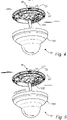
Figure 4 discloses an attachment part being attached by linear movement relative the base part. -
Figure 5 discloses an attachment part being attached by linear and rotational movement relative the base part. -
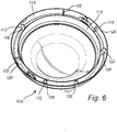
Figure 6 discloses a perspective view of the attachment part. - The present invention will now be described more fully hereinafter with reference to the accompanying drawings, in which currently preferred embodiments of the invention are shown. This invention may, however, be embodied in many different forms and should not be construed as limited to the embodiments set forth herein; rather, these embodiments are provided for thoroughness and completeness, and fully convey the scope of the invention to the skilled person.
-
Figure 1 discloses a perspective view of adevice 10, preferably acamera device 10, which is mounted to asurface 20. Thecamera device 10 is illustrated as a dome camera but may be embodied as another type of camera suitable for mounting to asurface 20. - The
surface 20 may be any type of surface that is suited for attachment of thecamera device 10, such as a wall or a ceiling. Typically, in case thedevice 10 is a camera device, thedevice 10 is preferably mounted at an elevated position in relation to its surroundings for achieving a desired field of view as illustrated inFigure 1 . This obviously necessitates that thedevice 10 is securely attached to thesurface 20. - The
device 10 comprises abase part 102 and anattachment part 104. Theattachment part 104 is attachable to thebase part 102, while thebase part 102 configured to be attached to thesurface 20. Thebase part 102 thus carries the weight of theattachment part 104 and forms a load bearing component of thedevice 10. The provision of thebase part 102 facilitates mounting of thedevice 10 to thesurface 20 as it may be secured by means of suitable fasteners 30 (shown inFigures 3 to 5 ) before theattachment part 104 is attached thereto. For instance, a camera unit (not shown) may be attached to thebase part 102 while theattachment part 104 forms a cover/housing such as a dome window which encloses the camera unit inside of thedevice 10. Theattachment part 104 may thus be partially or entirely transparent such that a camera unit arranged inside of theattachment part 104 can achieve a satisfactory image quality. Thebase part 102 and theattachment part 104 are shown being provided with corresponding circular shapes, but is to be realized that thebase part 102 and/or theattachment part 104 could be provided with other shapes as well such as rectangular or hexagonal etc. -
Figure 2 shows thedevice 10 from a posterior view in which thebase part 102 is shown from the side intended to be facing thesurface 20. Thebase part 102 may be formed from a plastic material or e.g. from a metallic material. Thebase part 102 is provided with a keyhole-shapedopening 106 for receiving a fastener 30 (shown inFigure 3 ) for attaching thebase part 102 to thesurface 20. The keyhole-shapedopening 106 facilitates attachment and removal of thebase part 102 to/from thesurface 20, as thefasteners 30 only needs to be loosened, and not being completely removed, for removal of thebase part 102. - Preferably are a plurality of keyhole-shaped
openings 106 provided such as three or more. The keyhole-shapedopenings 106 are preferably arranged peripherally at thebase part 102, i.e. near the perimeter thereof. The keyhole-shapedopenings 106 may be evenly angularly distributed around the periphery of thebase part 102. The keyhole-shapedopenings 106 may further be unevenly distributed around the periphery of thebase part 102, providing only one possible relative orientation of thebase part 102 and thefasteners 30 as well as one possible relative orientation of theattachment part 104 and thebase part 102 for allowing assembly of the twoparts - Each keyhole-shaped
opening 106 comprises afirst segment 108 permitting passage of a head 32 (shown inFigure 3 ) of thefastener 30, thus allowing thebase part 102 to be removed from thesurface 20 without completely removing thefastener 30. Asecond segment 110 of each keyhole-shapedopening 106 permits passage of ashaft 34 of thefastener 30 but prevents passage of thehead 32 thereof. Thebase part 102 is for securing thebase part 102 to thesurface 20 configured to be adjusted in relation to thefastener 30 such that thefastener 30 is arranged in thesecond segment 110. - In order to reduce the risk of the
base part 102, and thus theentire device 10, unintentionally detaching from thefasteners 30, theattachment part 104 is provided with aprotrusion 122. Theprotrusion 122 is configured to, in an assembled state of thebase part 102 and theattachment part 104, restrict relative movement between thefastener 30 and thebase part 102. As is visible fromFigures 2 and 3 , this may be achieved as theprotrusion 122 is configured to be arranged in the proximity of thehead 32 of thefastener 30 when theattachment part 104 is attached to thebase part 102 such that thehead 32 cannot pass through thefirst segment 108. - The
protrusion 122 may extend such that it is arranged in thefirst segment 108 of the keyhole-shapedopening 106 when theattachment part 104 is attached to thebase part 102, thus preventing thefastener 30 to move in relation to thebase part 102 from thesecond segment 110 to thefirst segment 108. Preferably is oneprotrusion 122 provided for each keyhole-shapedopening 106. It is however also feasible thatless protrusions 122 are provided than keyhole-shapedopenings 106. - The
protrusion 122 may further extend such that it is arranged in the proximity of the keyhole-shapedopening 106 when theattachment part 104 is attached to thebase part 102. In the proximity in this context means closer to thebase part 102 than the heigth of thehead 32 of thefastener 30, such that the movement of thefastener 30 in relation to thebase part 102 will be obstructed by theprotrusion 122. Theprotrusion 122 may thus not necessarily extend into the keyhole-shapedopening 106 but to a position above it which is sufficiently close to avoid thehead 32 of thefastener 30 bewteen theprotrusion 122 and thebase part 102. Theprotrusion 122 will thus be arranged such that it prevents thefastener 30 to move in relation to thebase part 102 from thesecond segment 110 to thefirst segment 108 when theattachment part 104 is attached to thebase part 102. - The
base part 102 may further be provided with anadditional opening 114 for receiving anadditional protrusion 112 on theattachment part 104. A plurality ofadditional protrusions 112 and correspondingadditional openings 112 may be provided, as illustrated inFigure 2 . Theadditional protrusions 112 and the correspondingadditional openings 112 are preferably arranged peripherally at theattachment part 104 and thebase part 102 respectively, i.e. near the perimeter of eachrespective part additional protrusions 112 and the correspondingadditional openings 112 are configured to facilitate correct orientation of theattachment part 104 when attached to thebase part 102. Theadditional protrusions 112 and the correspondingadditional openings 114 may thus be arranged such that only one possible relative orientation of theattachment part 104 and thebase part 102 is possible. For instance may theadditional protrusions 112 and the correspondingadditional openings 112 be unevenly distributed around the periphery of thebase part 102 and theattachment part 104 respectively. Theadditional protrusions 112 and the correspondingadditional openings 112 may further be provided with a shape and/or orientation that only permits one relative orientation of thebase part 102 and theattachment part 104. - Each
additional opening 114 may further be provided with an elongated shape such that theadditional protrusion 112 can move in relation to theadditional opening 114. Theadditional opening 114 may for instance be provided with a semi-circular elongated shape, which allows theadditional protrusion 112 to move therein as theattachment part 104 is rotated in relation to thebase part 102. A first end of theadditional opening 114 may by its interaction with theadditional protrusion 112 define the secured relative position of thebase part 102 and theattachment part 104, in which thefastener 30 is arranged in thesecond segment 110 of the keyhole-shapedopening 106. A second end of theadditional opening 114 opposite the first end may by its interaction with theadditional protrusion 112 define a released relative position of thebase part 102 and theattachment part 104, in which thefastener 30 is arranged in thefirst segment 108 of the keyhole-shapedopening 106 . - The
device 10 may further be provided with anattachment part fastener 124 for securing theattachment part 104 to thebase part 102. More than oneattachment part fastener 124 is preferably provided. - The
attachment part fasteners 124 may be resilient clips allowing snap-lock securing of theattachment part 104 to thebase part 102. Theattachment part fasteners 124 may further comprise fasteners such as a screw or similar. - The
attachment part 104 is preferably releasably attached to thebase part 102, whereby theattachment part fasteners 124 are releasable for instance by resiliently pressing theattachment part fasteners 124 out of snap-lock engagement. -
Figure 3 shows a detail view of how theprotrusion 122 is arranged in the keyhole-shapedopening 106. Theprotrusion 122 is shown having a rectangular oblong cross-sectional shape, but is it to be realized that the protrusion can be provided with another cross-sectional shape as well such as circular, oval or square. Theprotrusion 122 may be provided with a shape corresponding to the shape of thefirst segment 108 of the keyhole-shapedopening 106, such that it can be arranged in thefirst segment 108. - The
protrusion 122 may be configured to prevent attachment of theattachment part 104 to thebase part 102 if thefastener 30 is not correctly arranged in thesecond segment 110 of the keyhole-shapedopening 106. - For instance, the
protrusion 122 may be provided with a cross-sectional shape that occupies a sufficient amount of space in thefirst segment 108 of the keyhole-shapedopening 106 that theprotrusion 122 cannot be inserted into or sufficiently close to thefirst segment 108 if either of thehead 32 or theshaft 34 of thefastener 30 is arranged in thefirst segment 108. - The
protrusion 122 is, when theattachment part 104 is attached to thebase part 102, arranged such that thefastener 30 is prevented from movement into thefirst segment 108 of the keyhole-shapedopening 106. - This may be achieved by the
protrusion 122 extending such that it is arranged sufficiently close to the keyhole-shapedopening 106 such that thehead 32 of thefastener 30 will make contact with theprotrusion 122 if relative movement is induced between thebase part 102 and thefastener 30. - The
protrusion 122 may alternatively extend into or to a proximal position above thefirst segment 108 of the keyhole-shapedopening 106, preferably near the transition betweenfirst segment 108 andsecond segment 110 thereof. Alternatively, in an embodiment where thesecond segment 110 has a sufficient elongated extension in the plane of thebase part 102 to accommodate both thefastener 30 and theprotrusion 122, theprotrusion 122 can be arranged in thesecond segment 110 or in a proximal position above thesecond segment 110 in the assembled state of thedevice 10. Theprotrusion 122 should in such an embodiment be arranged between thefastener 30 and thefirst segment 108, such that thefastener 30 cannot move past theprotrusion 122 in thesecond segment 110 to thefirst segment 108. - The
protrusion 122 may further function as a guide for achieving correct alignment between thebase part 102 and theattachment part 104. - The
attachment part 104 is illustrated inFigure 3 andFigure 4 as being attachable to thebase part 102 by linear relative movement between theattachment part 104 and thebase part 102. In other words, theattachment part 104 can be attached to thebase part 102 by pushing theattachment part 104 together with thebase part 102. Theattachment part fasteners 124 may be configured to snap into a locking position once theattachment part 104 is correctly positioned in relation to thebase part 102. - As illustrated in
Figure 5 , theattachment part 104 may further in addition or as an alternative to the linear movement be configured to be attached to thebase part 102 by means of a rotational relative movement between theattachment part 104 and thebase part 102. Theattachment part 104 may thus be arranged in connection with thebase part 102, whereafter theattachment part 104 is twisted/rotated in relation to thebase part 102 until the correct relative position is achieved. Theattachment part fasteners 124 may be configured to snap into a locking position once theattachment part 104 is correctly positioned in relation to thebase part 102. - As can be further seen in
Figure 3 , theattachment part 104 may be provided with an outerannular bottom section 116, an innerannular bottom section 118 and abridging section 120 connecting the outerannular bottom section 116 and the innerannular bottom section 118. The outerannular bottom section 116 and the innerannular bottom section 118 may be integrally formed with theattachment part 104. The outerannular bottom section 116 may be formed by the exterior of theattachment part 104, with the innerannular bottom section 118 forming an annular wall arranged interiorly of the outerannular section 116. - The
bridging section 120 may be integrally formed with and provide rigidity to the outer and innerannular bottoms sections bottom sections openings 106 along with thehead 32 of thefastener 30 is arranged when theattachment part 104 is attached to thebase part 102. Thefastener 30 is thus hidden and cannot be removed without removing theattachment part 104 from thebase part 102 first. - The
bridging section 120 may further comprise adistal end 122 which forms theprotrusion 122. Theprotrusion 122 is thus formed integrally with thebridging section 120 which is connected to the inner and outerannular bottom section - Similarly, as is shown in
Figure 6 which shows theattachment part 104 in a perspective view, eachadditional protrusion 112 may be formed as adistal end 112 on arespective bridging section 120 between the inner and outer annularbottom sections additional protrusion 112, as well as theprotrusion 122, may thus be formed as a part of astrengthening bridging section 120 which provides structural rigidity to theattachment part 104. - It will be appreciated that the present invention is not limited to the embodiments shown. Several modifications and variations are thus conceivable within the scope of the invention which thus is exclusively defined by the appended claims.
Claims (13)
- A device (10) configured for mounting to a surface (20), comprising a base part (102) and an attachment part (104), the attachment part (104) being attachable to the base part (102), wherein the base part (102) is provided with a keyhole-shaped opening (106) for receiving a fastener (30) comprising a head (32) and a shaft (34) for attaching the base part (102) to the surface (20), the keyhole-shaped opening (106) comprises a first segment (108) permitting passage of the head (32) and shaft (34) and a second segment (110) permitting passage of the shaft (34) but preventing passage of the head (32), wherein the attachment part (104) comprises a protrusion (122) which in an assembled state of the base part (102) and the attachment part (104) restricts relative movement between the fastener (30) and the base part (102).
- The device (10) according to claim 1, wherein the base part (102) is a camera base part (102).
- The device (10) according to claim 1 or 2, wherein the attachment part (104) is a dome window (104).
- The device (10) according to any of the preceding claims, wherein the keyhole-shaped opening (106) and the protrusion (122) are peripherally arranged on the base part (102) and the attachment part (104) respectively.
- The device (10) according to any of the preceding claims, wherein the attachment part (104) is attachable to the base part (102) by linear relative movement between the attachment part (104) and the base part (102).
- The device (10) according to any of the preceding claims, wherein the attachment part (104) is attachable to the base part (102) by rotational relative movement between the attachment part (104) and the base part (102).
- The device (10) according to any of the preceding claims, wherein the protrusion (122) in the assembled state of the attachment part (104) and the base part (102) extends into the keyhole-shaped opening (106).
- The device (10) according to any of the preceding claims, wherein the base part (102) comprises a plurality of keyhole-shaped openings (106).
- The device (10) according to claim 8, wherein the attachment part (104) comprises a plurality of protrusions (122).
- The device (10) according to claim 8 or 9, wherein the keyhole-shaped openings (106) are circumferentially distributed on the base part (102).
- The device (10) according to any of the preceding claims, wherein the attachment part (104) comprises an additional protrusion (112) configured to be received by an additional opening (114) provided in the base part (102) in the assembled state.
- The device (10) according to any one of the preceding claims, wherein the attachment part (104) comprises an outer annular bottom section (116), an inner annular bottom section (118) and a bridging section (120) connecting the outer annular bottom section (116) and the inner annular bottom section (118), wherein the bridging section (120) comprises a distal end (122) forming the protrusion (122).
- The device (10) according to any of the preceding claims, wherein the attachment part (104) is releasably attached to the base part (102).
Priority Applications (6)
| Application Number | Priority Date | Filing Date | Title |
|---|---|---|---|
| EP20213501.8A EP4012677B1 (en) | 2020-12-11 | 2020-12-11 | A device configured for mounting to a surface |
| KR1020210152191A KR102775381B1 (en) | 2020-12-11 | 2021-11-08 | A device configured for mounting to a surface |
| US17/522,575 US11914272B2 (en) | 2020-12-11 | 2021-11-09 | Device configured for mounting to a surface |
| TW110143917A TWI920169B (en) | 2020-12-11 | 2021-11-25 | A device configured for mounting to a surface |
| JP2021196883A JP7619931B2 (en) | 2020-12-11 | 2021-12-03 | Device configured for mounting on a surface |
| CN202111474844.6A CN114623362B (en) | 2020-12-11 | 2021-12-03 | Device configured for mounting to a surface |
Applications Claiming Priority (1)
| Application Number | Priority Date | Filing Date | Title |
|---|---|---|---|
| EP20213501.8A EP4012677B1 (en) | 2020-12-11 | 2020-12-11 | A device configured for mounting to a surface |
Publications (3)
| Publication Number | Publication Date |
|---|---|
| EP4012677A1 true EP4012677A1 (en) | 2022-06-15 |
| EP4012677B1 EP4012677B1 (en) | 2024-11-27 |
| EP4012677C0 EP4012677C0 (en) | 2024-11-27 |
Family
ID=74186421
Family Applications (1)
| Application Number | Title | Priority Date | Filing Date |
|---|---|---|---|
| EP20213501.8A Active EP4012677B1 (en) | 2020-12-11 | 2020-12-11 | A device configured for mounting to a surface |
Country Status (4)
| Country | Link |
|---|---|
| US (1) | US11914272B2 (en) |
| EP (1) | EP4012677B1 (en) |
| JP (1) | JP7619931B2 (en) |
| KR (1) | KR102775381B1 (en) |
Citations (3)
| Publication number | Priority date | Publication date | Assignee | Title |
|---|---|---|---|---|
| US4369340A (en) * | 1980-09-04 | 1983-01-18 | Bell Telephone Laboratories, Incorporated | Wall telephone adapter assembly |
| WO2007081099A1 (en) * | 2006-01-13 | 2007-07-19 | Semyung Electronics Co., Ltd. | Dome type infrared ray sensor |
| US20170168376A1 (en) * | 2015-12-10 | 2017-06-15 | Axis Ab | Mounting bracket for mounting a monitoring camera |
Family Cites Families (19)
| Publication number | Priority date | Publication date | Assignee | Title |
|---|---|---|---|---|
| US2810600A (en) | 1954-11-26 | 1957-10-22 | Schlage Lock Co | Nonreversible keyhole connection for mounting plates |
| FR2452022A1 (en) | 1979-03-23 | 1980-10-17 | Peugeot | Toggle bolt for sheet metal - locks in keyhole after quarter turn with arched elastic tongue engaging hole to stop further rotation |
| JPH07162723A (en) * | 1993-12-10 | 1995-06-23 | Atsumi Electron Corp Ltd | Monitoring camera |
| US5689304A (en) | 1996-03-04 | 1997-11-18 | Philips Electronic North America Corporation | Indoor/outdoor surveillance housing |
| US6309183B1 (en) * | 1997-05-05 | 2001-10-30 | King Of Fans, Inc. | Blade arm |
| KR200190661Y1 (en) * | 1997-10-02 | 2000-08-01 | 서병일 | Housing for dome shaped surveillance camera |
| KR100709561B1 (en) * | 2000-11-20 | 2007-04-20 | 삼성전자주식회사 | Dome camera |
| JP4507428B2 (en) * | 2000-11-30 | 2010-07-21 | パナソニック株式会社 | Camera device |
| KR200323531Y1 (en) * | 2003-05-15 | 2003-08-21 | 신현국 | A security camera |
| JP4464843B2 (en) * | 2005-02-09 | 2010-05-19 | パナソニック株式会社 | Surveillance camera device |
| TWI322230B (en) | 2005-06-30 | 2010-03-21 | Delta Electronics Inc | Fan module and its fan casing |
| US7425101B2 (en) | 2006-05-26 | 2008-09-16 | Yi-Jen Cheng | Image adjusting assembly for a monitoring camera |
| KR200440303Y1 (en) | 2006-12-15 | 2008-06-05 | 오닉스시스템주식회사 | Dome type security camera device |
| KR200452725Y1 (en) * | 2009-04-07 | 2011-03-16 | 정성호 | Easy to install ball dome surveillance camera |
| JP5892586B2 (en) | 2011-10-25 | 2016-03-23 | 矢崎エナジーシステム株式会社 | Electronic equipment |
| JP2014239394A (en) * | 2013-06-10 | 2014-12-18 | キヤノン株式会社 | Imaging apparatus |
| JP2017161676A (en) * | 2016-03-09 | 2017-09-14 | キヤノン株式会社 | Storage structure for case fall prevention wire in imaging device |
| EP3333816B1 (en) * | 2016-12-09 | 2018-10-03 | Axis AB | Camera arrangement with illuminator |
| EP3514436B1 (en) * | 2018-01-17 | 2019-12-11 | Axis AB | A fastening arrangement, a fastening arrangement kit and use of a fastening arrangement kit |
-
2020
- 2020-12-11 EP EP20213501.8A patent/EP4012677B1/en active Active
-
2021
- 2021-11-08 KR KR1020210152191A patent/KR102775381B1/en active Active
- 2021-11-09 US US17/522,575 patent/US11914272B2/en active Active
- 2021-12-03 JP JP2021196883A patent/JP7619931B2/en active Active
Patent Citations (3)
| Publication number | Priority date | Publication date | Assignee | Title |
|---|---|---|---|---|
| US4369340A (en) * | 1980-09-04 | 1983-01-18 | Bell Telephone Laboratories, Incorporated | Wall telephone adapter assembly |
| WO2007081099A1 (en) * | 2006-01-13 | 2007-07-19 | Semyung Electronics Co., Ltd. | Dome type infrared ray sensor |
| US20170168376A1 (en) * | 2015-12-10 | 2017-06-15 | Axis Ab | Mounting bracket for mounting a monitoring camera |
Also Published As
| Publication number | Publication date |
|---|---|
| JP7619931B2 (en) | 2025-01-22 |
| US11914272B2 (en) | 2024-02-27 |
| US20220187690A1 (en) | 2022-06-16 |
| JP2022093292A (en) | 2022-06-23 |
| EP4012677B1 (en) | 2024-11-27 |
| CN114623362A (en) | 2022-06-14 |
| KR102775381B1 (en) | 2025-02-28 |
| TW202229761A (en) | 2022-08-01 |
| KR20220083572A (en) | 2022-06-20 |
| EP4012677C0 (en) | 2024-11-27 |
Similar Documents
| Publication | Publication Date | Title |
|---|---|---|
| EP1036383B1 (en) | Apparatus for mounting a surveillance camera | |
| EP2657762B1 (en) | Top cover assembly for a monitoring camera | |
| US20070076441A1 (en) | Positive locking light fixture with faceplate | |
| US20060147194A1 (en) | Connect/disconnect mechanism for a surveillance camera head | |
| US20030207601A1 (en) | Socket | |
| EP1182726B1 (en) | On-vehicle rod antenna device | |
| JP2019105822A (en) | Camera arrangement | |
| EP4012677B1 (en) | A device configured for mounting to a surface | |
| CN114623362B (en) | Device configured for mounting to a surface | |
| US5461938A (en) | Control cable end connector | |
| KR20100065897A (en) | Sensor fixing bracket having locker | |
| EP1078342B1 (en) | Surveillance camera housing with mounting unit | |
| TWI920169B (en) | A device configured for mounting to a surface | |
| EP1892453A1 (en) | Locking device for computer equipment extension arm | |
| US20030103833A1 (en) | Retained hardware system and method | |
| TWI867201B (en) | Nut locking system and electronic device comprising such nut locking system | |
| US6095670A (en) | Circular mounting plate adapter for attaching an exit sign to a junction box | |
| KR101228317B1 (en) | Security camera | |
| KR19990014418U (en) | Dome-shaped housing for surveillance camera | |
| TWI859459B (en) | A protective cover assembly for a surveillance camera | |
| CN220232997U (en) | Knob switch structure and warm air blower | |
| KR200490256Y1 (en) | Driving module assembly for door lock | |
| JP5517684B2 (en) | Lock mechanism | |
| CN223726014U (en) | Bracket assembly and camera system | |
| US20260093164A1 (en) | Camera attachment member |
Legal Events
| Date | Code | Title | Description |
|---|---|---|---|
| PUAI | Public reference made under article 153(3) epc to a published international application that has entered the european phase |
Free format text: ORIGINAL CODE: 0009012 |
|
| STAA | Information on the status of an ep patent application or granted ep patent |
Free format text: STATUS: REQUEST FOR EXAMINATION WAS MADE |
|
| 17P | Request for examination filed |
Effective date: 20211104 |
|
| AK | Designated contracting states |
Kind code of ref document: A1 Designated state(s): AL AT BE BG CH CY CZ DE DK EE ES FI FR GB GR HR HU IE IS IT LI LT LU LV MC MK MT NL NO PL PT RO RS SE SI SK SM TR |
|
| STAA | Information on the status of an ep patent application or granted ep patent |
Free format text: STATUS: EXAMINATION IS IN PROGRESS |
|
| 17Q | First examination report despatched |
Effective date: 20230104 |
|
| GRAP | Despatch of communication of intention to grant a patent |
Free format text: ORIGINAL CODE: EPIDOSNIGR1 |
|
| STAA | Information on the status of an ep patent application or granted ep patent |
Free format text: STATUS: GRANT OF PATENT IS INTENDED |
|
| INTG | Intention to grant announced |
Effective date: 20240701 |
|
| GRAS | Grant fee paid |
Free format text: ORIGINAL CODE: EPIDOSNIGR3 |
|
| GRAA | (expected) grant |
Free format text: ORIGINAL CODE: 0009210 |
|
| STAA | Information on the status of an ep patent application or granted ep patent |
Free format text: STATUS: THE PATENT HAS BEEN GRANTED |
|
| AK | Designated contracting states |
Kind code of ref document: B1 Designated state(s): AL AT BE BG CH CY CZ DE DK EE ES FI FR GB GR HR HU IE IS IT LI LT LU LV MC MK MT NL NO PL PT RO RS SE SI SK SM TR |
|
| REG | Reference to a national code |
Ref country code: GB Ref legal event code: FG4D |
|
| REG | Reference to a national code |
Ref country code: CH Ref legal event code: EP |
|
| REG | Reference to a national code |
Ref country code: DE Ref legal event code: R096 Ref document number: 602020041982 Country of ref document: DE |
|
| REG | Reference to a national code |
Ref country code: IE Ref legal event code: FG4D |
|
| U01 | Request for unitary effect filed |
Effective date: 20241127 |
|
| U07 | Unitary effect registered |
Designated state(s): AT BE BG DE DK EE FI FR IT LT LU LV MT NL PT RO SE SI Effective date: 20241203 |
|
| U20 | Renewal fee for the european patent with unitary effect paid |
Year of fee payment: 5 Effective date: 20241218 |
|
| PG25 | Lapsed in a contracting state [announced via postgrant information from national office to epo] |
Ref country code: HR Free format text: LAPSE BECAUSE OF FAILURE TO SUBMIT A TRANSLATION OF THE DESCRIPTION OR TO PAY THE FEE WITHIN THE PRESCRIBED TIME-LIMIT Effective date: 20241127 Ref country code: IS Free format text: LAPSE BECAUSE OF FAILURE TO SUBMIT A TRANSLATION OF THE DESCRIPTION OR TO PAY THE FEE WITHIN THE PRESCRIBED TIME-LIMIT Effective date: 20250327 |
|
| PG25 | Lapsed in a contracting state [announced via postgrant information from national office to epo] |
Ref country code: ES Free format text: LAPSE BECAUSE OF FAILURE TO SUBMIT A TRANSLATION OF THE DESCRIPTION OR TO PAY THE FEE WITHIN THE PRESCRIBED TIME-LIMIT Effective date: 20241127 |
|
| PG25 | Lapsed in a contracting state [announced via postgrant information from national office to epo] |
Ref country code: NO Free format text: LAPSE BECAUSE OF FAILURE TO SUBMIT A TRANSLATION OF THE DESCRIPTION OR TO PAY THE FEE WITHIN THE PRESCRIBED TIME-LIMIT Effective date: 20250227 |
|
| PG25 | Lapsed in a contracting state [announced via postgrant information from national office to epo] |
Ref country code: GR Free format text: LAPSE BECAUSE OF FAILURE TO SUBMIT A TRANSLATION OF THE DESCRIPTION OR TO PAY THE FEE WITHIN THE PRESCRIBED TIME-LIMIT Effective date: 20250228 |
|
| PG25 | Lapsed in a contracting state [announced via postgrant information from national office to epo] |
Ref country code: PL Free format text: LAPSE BECAUSE OF FAILURE TO SUBMIT A TRANSLATION OF THE DESCRIPTION OR TO PAY THE FEE WITHIN THE PRESCRIBED TIME-LIMIT Effective date: 20241127 |
|
| PG25 | Lapsed in a contracting state [announced via postgrant information from national office to epo] |
Ref country code: RS Free format text: LAPSE BECAUSE OF FAILURE TO SUBMIT A TRANSLATION OF THE DESCRIPTION OR TO PAY THE FEE WITHIN THE PRESCRIBED TIME-LIMIT Effective date: 20250227 |
|
| PG25 | Lapsed in a contracting state [announced via postgrant information from national office to epo] |
Ref country code: SM Free format text: LAPSE BECAUSE OF FAILURE TO SUBMIT A TRANSLATION OF THE DESCRIPTION OR TO PAY THE FEE WITHIN THE PRESCRIBED TIME-LIMIT Effective date: 20241127 |
|
| PG25 | Lapsed in a contracting state [announced via postgrant information from national office to epo] |
Ref country code: SK Free format text: LAPSE BECAUSE OF FAILURE TO SUBMIT A TRANSLATION OF THE DESCRIPTION OR TO PAY THE FEE WITHIN THE PRESCRIBED TIME-LIMIT Effective date: 20241127 |
|
| PG25 | Lapsed in a contracting state [announced via postgrant information from national office to epo] |
Ref country code: CZ Free format text: LAPSE BECAUSE OF FAILURE TO SUBMIT A TRANSLATION OF THE DESCRIPTION OR TO PAY THE FEE WITHIN THE PRESCRIBED TIME-LIMIT Effective date: 20241127 |
|
| REG | Reference to a national code |
Ref country code: CH Ref legal event code: PL |
|
| PG25 | Lapsed in a contracting state [announced via postgrant information from national office to epo] |
Ref country code: MC Free format text: LAPSE BECAUSE OF FAILURE TO SUBMIT A TRANSLATION OF THE DESCRIPTION OR TO PAY THE FEE WITHIN THE PRESCRIBED TIME-LIMIT Effective date: 20241127 |
|
| PLBE | No opposition filed within time limit |
Free format text: ORIGINAL CODE: 0009261 |
|
| STAA | Information on the status of an ep patent application or granted ep patent |
Free format text: STATUS: NO OPPOSITION FILED WITHIN TIME LIMIT |
|
| PG25 | Lapsed in a contracting state [announced via postgrant information from national office to epo] |
Ref country code: CH Free format text: LAPSE BECAUSE OF NON-PAYMENT OF DUE FEES Effective date: 20241231 |
|
| PG25 | Lapsed in a contracting state [announced via postgrant information from national office to epo] |
Ref country code: IE Free format text: LAPSE BECAUSE OF NON-PAYMENT OF DUE FEES Effective date: 20241211 |
|
| 26N | No opposition filed |
Effective date: 20250828 |
|
| U20 | Renewal fee for the european patent with unitary effect paid |
Year of fee payment: 6 Effective date: 20251119 |
|
| PGFP | Annual fee paid to national office [announced via postgrant information from national office to epo] |
Ref country code: GB Payment date: 20251120 Year of fee payment: 6 |
|
| PG25 | Lapsed in a contracting state [announced via postgrant information from national office to epo] |
Ref country code: CY Free format text: LAPSE BECAUSE OF FAILURE TO SUBMIT A TRANSLATION OF THE DESCRIPTION OR TO PAY THE FEE WITHIN THE PRESCRIBED TIME-LIMIT Effective date: 20241127 |