EP4012531A1 - Système autonome d'encartage 3d d'un centre de traitement de données - Google Patents
Système autonome d'encartage 3d d'un centre de traitement de données Download PDFInfo
- Publication number
- EP4012531A1 EP4012531A1 EP21172210.3A EP21172210A EP4012531A1 EP 4012531 A1 EP4012531 A1 EP 4012531A1 EP 21172210 A EP21172210 A EP 21172210A EP 4012531 A1 EP4012531 A1 EP 4012531A1
- Authority
- EP
- European Patent Office
- Prior art keywords
- images
- cameras
- imaging system
- vertical position
- distances
- Prior art date
- Legal status (The legal status is an assumption and is not a legal conclusion. Google has not performed a legal analysis and makes no representation as to the accuracy of the status listed.)
- Granted
Links
- 238000013507 mapping Methods 0.000 title description 2
- 238000003384 imaging method Methods 0.000 claims abstract description 86
- 238000012634 optical imaging Methods 0.000 claims abstract description 10
- 238000000034 method Methods 0.000 claims description 23
- 238000004891 communication Methods 0.000 claims description 6
- 230000003287 optical effect Effects 0.000 description 15
- 230000015654 memory Effects 0.000 description 13
- 230000000875 corresponding effect Effects 0.000 description 7
- 230000008447 perception Effects 0.000 description 7
- 230000002596 correlated effect Effects 0.000 description 5
- 238000012545 processing Methods 0.000 description 4
- 238000004140 cleaning Methods 0.000 description 3
- 238000001514 detection method Methods 0.000 description 3
- 238000013461 design Methods 0.000 description 2
- 238000004519 manufacturing process Methods 0.000 description 2
- 230000007246 mechanism Effects 0.000 description 2
- 238000010276 construction Methods 0.000 description 1
- 230000001276 controlling effect Effects 0.000 description 1
- 238000010586 diagram Methods 0.000 description 1
- 238000005516 engineering process Methods 0.000 description 1
- 230000007613 environmental effect Effects 0.000 description 1
- 230000006870 function Effects 0.000 description 1
- 238000010801 machine learning Methods 0.000 description 1
- 238000012423 maintenance Methods 0.000 description 1
- 238000012544 monitoring process Methods 0.000 description 1
- 230000000737 periodic effect Effects 0.000 description 1
- 238000012805 post-processing Methods 0.000 description 1
- 230000008569 process Effects 0.000 description 1
- 230000008439 repair process Effects 0.000 description 1
- 230000004044 response Effects 0.000 description 1
- 239000007921 spray Substances 0.000 description 1
- 238000003860 storage Methods 0.000 description 1
- 230000000007 visual effect Effects 0.000 description 1
Images


Classifications
-
- G—PHYSICS
- G05—CONTROLLING; REGULATING
- G05D—SYSTEMS FOR CONTROLLING OR REGULATING NON-ELECTRIC VARIABLES
- G05D1/00—Control of position, course or altitude of land, water, air, or space vehicles, e.g. automatic pilot
- G05D1/02—Control of position or course in two dimensions
- G05D1/021—Control of position or course in two dimensions specially adapted to land vehicles
- G05D1/0231—Control of position or course in two dimensions specially adapted to land vehicles using optical position detecting means
- G05D1/0246—Control of position or course in two dimensions specially adapted to land vehicles using optical position detecting means using a video camera in combination with image processing means
- G05D1/0248—Control of position or course in two dimensions specially adapted to land vehicles using optical position detecting means using a video camera in combination with image processing means in combination with a laser
-
- G—PHYSICS
- G01—MEASURING; TESTING
- G01S—RADIO DIRECTION-FINDING; RADIO NAVIGATION; DETERMINING DISTANCE OR VELOCITY BY USE OF RADIO WAVES; LOCATING OR PRESENCE-DETECTING BY USE OF THE REFLECTION OR RERADIATION OF RADIO WAVES; ANALOGOUS ARRANGEMENTS USING OTHER WAVES
- G01S17/00—Systems using the reflection or reradiation of electromagnetic waves other than radio waves, e.g. lidar systems
- G01S17/88—Lidar systems specially adapted for specific applications
- G01S17/89—Lidar systems specially adapted for specific applications for mapping or imaging
-
- G—PHYSICS
- G01—MEASURING; TESTING
- G01S—RADIO DIRECTION-FINDING; RADIO NAVIGATION; DETERMINING DISTANCE OR VELOCITY BY USE OF RADIO WAVES; LOCATING OR PRESENCE-DETECTING BY USE OF THE REFLECTION OR RERADIATION OF RADIO WAVES; ANALOGOUS ARRANGEMENTS USING OTHER WAVES
- G01S17/00—Systems using the reflection or reradiation of electromagnetic waves other than radio waves, e.g. lidar systems
- G01S17/02—Systems using the reflection of electromagnetic waves other than radio waves
- G01S17/06—Systems determining position data of a target
- G01S17/08—Systems determining position data of a target for measuring distance only
-
- G—PHYSICS
- G01—MEASURING; TESTING
- G01S—RADIO DIRECTION-FINDING; RADIO NAVIGATION; DETERMINING DISTANCE OR VELOCITY BY USE OF RADIO WAVES; LOCATING OR PRESENCE-DETECTING BY USE OF THE REFLECTION OR RERADIATION OF RADIO WAVES; ANALOGOUS ARRANGEMENTS USING OTHER WAVES
- G01S17/00—Systems using the reflection or reradiation of electromagnetic waves other than radio waves, e.g. lidar systems
- G01S17/86—Combinations of lidar systems with systems other than lidar, radar or sonar, e.g. with direction finders
-
- G—PHYSICS
- G05—CONTROLLING; REGULATING
- G05D—SYSTEMS FOR CONTROLLING OR REGULATING NON-ELECTRIC VARIABLES
- G05D1/00—Control of position, course or altitude of land, water, air, or space vehicles, e.g. automatic pilot
- G05D1/02—Control of position or course in two dimensions
- G05D1/021—Control of position or course in two dimensions specially adapted to land vehicles
- G05D1/0231—Control of position or course in two dimensions specially adapted to land vehicles using optical position detecting means
- G05D1/0246—Control of position or course in two dimensions specially adapted to land vehicles using optical position detecting means using a video camera in combination with image processing means
- G05D1/0251—Control of position or course in two dimensions specially adapted to land vehicles using optical position detecting means using a video camera in combination with image processing means extracting 3D information from a plurality of images taken from different locations, e.g. stereo vision
-
- G—PHYSICS
- G05—CONTROLLING; REGULATING
- G05D—SYSTEMS FOR CONTROLLING OR REGULATING NON-ELECTRIC VARIABLES
- G05D1/00—Control of position, course or altitude of land, water, air, or space vehicles, e.g. automatic pilot
- G05D1/02—Control of position or course in two dimensions
- G05D1/021—Control of position or course in two dimensions specially adapted to land vehicles
- G05D1/0268—Control of position or course in two dimensions specially adapted to land vehicles using internal positioning means
- G05D1/0274—Control of position or course in two dimensions specially adapted to land vehicles using internal positioning means using mapping information stored in a memory device
-
- G—PHYSICS
- G06—COMPUTING; CALCULATING OR COUNTING
- G06V—IMAGE OR VIDEO RECOGNITION OR UNDERSTANDING
- G06V20/00—Scenes; Scene-specific elements
- G06V20/50—Context or environment of the image
- G06V20/52—Surveillance or monitoring of activities, e.g. for recognising suspicious objects
Definitions
- Datacenter interiors are complex, varied, and dynamic. This family of attributes encompasses construction, configuration, maintenance, and repairs of the datacenter and devices (servers, racks, etc.) within datacenters. Often, the actual arrangement and content of these attributes is somewhere between estimated and historical. Continual monitoring and cataloging of these datacenter attributes to mitigate the gap between theory and practice has been difficult to achieve.
- the state of datacenter rack contents is theorized based on various tools and processes, but the knowledge of the rack contents is not always entirely accurate.
- Conventional tools may store the state of datacenter rack contents using information that is manually entered, based on barcode asset tag information. However, if such rack content information is incorrect or only partially accurate, there may not be an easy way to correct such inaccuracies.
- the present disclosure provides for automated imaging systems and methods of imaging a physical location, such as a datacenter, with an automated guided vehicle (AGV).
- AGV may be equipped with a distance detection tool, such as a laser, to detect distances between the AGV and different surfaces within the physical location.
- the imaging system includes a plurality of cameras configured to capture a plurality of images from within the physical location. Moreover, the imaging system may correlate the distances with the plurality of images, and may generate a map of the physical location using the plurality of images and the distances.
- an automated imaging system including an automated guided vehicle having a propulsion system configured to move the vehicle, and a processor configured to control the motor and the steering system, an optical imaging system, the optical imaging system including a plurality of cameras, the cameras each being configured to have a respective field of view, the fields of view being at least partially non-overlapping with one another, a laser imaging system, the laser imaging system configured to scan a physical area to obtain respective distances between the vehicle and a plurality of locations within the physical area, and one or more processors configured to correlate a plurality of images taken by the cameras with the respective distances taken by the laser imaging system.
- the cameras are arranged in an array, and the array is moveable in a vertical direction.
- the cameras in the array may be spaced apart from one another in a circular pattern that extends in a plane parallel to the vertical direction.
- the plurality of images may include a first set of the images and a first set of the distances taken at a first vertical position and a second set of the images and a second set of the distances taken at a second vertical position, the first vertical position and the second vertical position being spaced apart from one another in the vertical direction.
- the one or more processors are further configured to combine the plurality of images taken by the cameras with the respective distances taken by the laser imaging system into a map.
- a wireless communication component may be configured to communicate with a remote computing system.
- the one or more processors may be configured to navigate the vehicle to a particular location based on communication from the remote computing system, the particular location corresponding to at least one of the plurality of images captured by the imaging system.
- the propulsion system may include a plurality of wheels rotatably mounted to the housing, a driving element configured to rotate the wheels, a steering system configured to pivot the wheels and navigate the housing along predetermined paths, and a processor configured to control the motor and the steering system.
- the method may include moving the automated guided vehicle to a plurality of locations within the physical area by a propulsion system that navigates the vehicle along predetermined paths, taking a plurality of images of the physical area with an optical imaging system coupled to the vehicle, the optical imaging system including a plurality of cameras, the cameras each being configured to have a respective field of view, the fields of view being at least partially non-overlapping with one another, scanning the physical area with a laser imaging system coupled to the vehicle to obtain a plurality of distances between the vehicle and a plurality of locations within the physical area, and correlating the plurality of images taken by the cameras with the plurality of distances taken by the laser imaging system.
- the method may further include locating the plurality of images and the plurality of distances relative to a known coordinate system of the physical area.
- the cameras may be arranged in an array, and the array is moveable in a vertical direction perpendicular to a floor of the physical area.
- the cameras in the array may be spaced apart from one another in a circular pattern that extends in a plane parallel to the vertical direction.
- the taking of the plurality of images may include taking a first set of the images and a first set of the distances at a first vertical position, moving the array from the first vertical position to a second vertical position spaced apart from the first vertical position in the vertical direction, and taking a second set of the images and a second set of the distances at the second vertical position.
- the imaging system may include a fixture having a rail extending in the vertical direction and a carriage coupled to the rail and movable relative to the rail in the vertical direction, the cameras being affixed to the carriage, and the moving of the array includes moving the carriage along the rail from the first vertical position to the second vertical position. Moving the carriage along the rail may be driven by a servo motor coupled to the carriage.
- the method may further include wirelessly sending the plurality of images and the plurality of distances to an image processor, the image processor being part of a computer that is remote from the automated guided vehicle.
- Moving the automated guided vehicle to the first target location may include moving the automated guided vehicle in a horizontal direction perpendicular to the vertical direction, and the fields of view extend from the plurality of cameras in a depth direction perpendicular to both the horizontal direction and the vertical direction.
- Yet another aspect of the disclosure provides a method of imaging a physical area with an automated guided vehicle, the method including moving the automated guided vehicle to a plurality of locations within the physical area by a propulsion system that navigates the vehicle along predetermined paths, taking an initial plurality of images of the physical area with an imaging system coupled to the vehicle, the imaging system including a plurality of cameras, the cameras each being configured to have a respective field of view, the fields of view being at least partially non-overlapping with one another, the taking of the initial plurality of images including taking a first set of the images at a first vertical position, moving the plurality of cameras from the first vertical position to a second vertical position spaced apart from the first vertical position in the vertical direction, and taking a second set of the images at the second vertical position, combining the initial plurality of images taken by the cameras into an initial single mosaic image using an image processor, and locating the initial plurality of images relative to a known coordinate system of the physical area.
- the method may further include receiving a selection of a location within the initial single mosaic image to move the automated guided vehicle to one of the plurality of locations and to take an updated plurality of images, and combining the updated plurality of images with the initial plurality of images taken by the cameras into an updated single mosaic image using the image processor.
- the technology relates generally to automated 3D imaging systems and methods of imaging a physical location using an automated guided vehicle (AGV).
- the physical location may be, for example, a datacenter or other indoor space.
- the automated imaging system may be configured to take a plurality of high resolution images of a datacenter rack, and combine the plurality of images into a single mosaic image.
- the system may parse location and barcode data from the combined mosaic image, thereby providing accurate current location and data information of the contents of the datacenter in an automated fashion.
- the automated imaging system may also provide real-time inventory location and data for commercial and retail racks of products that may not otherwise be obtained in an automated fashion.
- an AGV having an imaging system mounted thereon may be navigated through a physical location and used to capture 360 degree images of the location.
- the 360 degree images may then be used to generate a map of the physical location.
- the AGV may further detect distances between the AGV and various points within the physical location. The distances may be correlated with the captured 360 images and used to generate the map.
- the physical location as shown in this example and described in further examples herein is a datacenter. However, it should be understood that the physical location may be any of a variety of types of location, such as warehouses, manufacturing plants, etc.
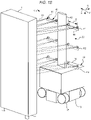
- Figs. 1B-1D illustrate just one example of an automated 3D imaging system 10 that may be used for imaging a datacenter rack 1.
- the automated imaging system 10 may include an AGV 12 having a housing 14 and a propulsion system 16 configured to move the AGV.
- the housing 14 is shown as being generally in the shape of a rectangular prism, but in other examples, the housing may have any other shape, such as a square prism, a cylinder, or the like. In other examples, the housing 14 may be omitted, such that mechanical and/or electrical components of the AGV 12 are exposed.
- the propulsion system 16 may include a motor and/or another driving element that is configured to rotate a plurality of wheels 18 that are rotatably mounted to the AGV 12, a steering system (not shown) that is configured to pivot the wheels and navigate the AGV 12 along predetermined paths, and a processor or control system 100 (described below with respect to FIG. 3 ) that is configured to control the motor and the steering system.
- the AGV 12 may also include sensors (not shown) for detecting conditions surrounding the AGV.
- sensors not shown
- the example configuration of the AGV 12 that is shown in FIGS. 1B through ID is merely one possible example of a flexible mobile robotics platform. In other examples, there may be many other configurations of components for moving the AGV 12 from one location to another.
- the location of the AGV may be known relative to a known 3D coordinate system of the physical area in which the AGV is navigated, such as a datacenter.
- the AGV 12 may read barcodes on the floor that are at known locations within the coordinate system. As it travels, the AGV 12 may synchronize its location relative to the barcodes.
- the automated imaging system 10 may also include an imaging system 20 coupled to the AGV 12.
- the imaging system 20 may include a plurality of cameras 30.
- the cameras 30 each may be configured to have a respective field of view 32.
- the fields of view 32 may be at least partially non-overlapping with one another, although in some examples, the fields of view may be entirely non-overlapping with one another.
- the fields of view 32 of the cameras 30 may extend away from the cameras in a depth direction D between an object, such as a datacenter rack 1, and the cameras.
- the automated imaging system 10 may include an image processor (e.g., the processor 111 shown in FIG. 3 ) configured to combine a plurality of images taken by the cameras 30 into a single mosaic image. Examples of the plurality of images and the single mosaic image will be shown and described below with respect to FIGS. 2A and 2B .
- the fields of view 32 are shown as extending towards a rack 1, the cameras 30 may be used to record the location of everything in the datacenter, including hallways, doors, columns, racks, fans, wireways, and the like.
- the image processing may be completely automated, such that the single mosaic image, a 360 image, and/or a map of the physical location may be generated from the captured images without human intervention.
- the cameras 30 may include one or more optical cameras and a laser imaging system, such as one or more LIDAR scanners. While the cameras 30 are shown in an arrangement of several rows stacked vertically, it should be understood that other arrangements are possible. For example, the cameras may be positioned in a 360 degree configuration about a vertical axis or a horizontal axis. As another example, the cameras may be arranged in a rosette such that the cameras collectively capture every angle around the AGV. In yet further examples, the cameras may be a single 360 degree camera.
- the optical cameras may obtain images that may be combined to obtain a visual map of the physical location. For example, captured images may be combined to generate a map of an entire datacenter, such that individual rack components may be visually identified.
- Fig. IE illustrates an example of using the AGV to detect distances between the AGV and various points within the physical location.
- the LIDAR scanners may scan in directions 33 to obtain location data and/or temperature data of the contents of the physical location, within a mapping envelope 34.
- the LIDAR scanners may obtain more accurate positional data than the optical cameras.
- the LIDAR scanners may obtain dimensional location of doors, columns, racks, fans, and wireways close to a ceiling 2 of the physical location.
- the dimensional accuracy of the LIDAR scanning may be within approximately plus or minus 10 mm.
- a single LIDAR scanner may be used, in which an internal electro-mechanical mirror system may move a single laser beam around, permitting approximately one thousand distances to be collected while the AGV is at a single location.
- a fixed array of lasers may be used.
- the system 10 is described as including LIDAR scanners, some examples only use optical images, while other examples combine optical and LIDAR data.
- the imaging system 20 may include a fixture 40 affixed to the housing, the fixture having a rail 42 extending in a vertical direction V perpendicular to the depth direction D, and a carriage 44 extending in a horizontal direction H perpendicular to the vertical direction and the depth direction.
- the cameras 30 may be affixed to the carriage 44.
- the cameras 30 may be arranged along the carriage 44 in an array extending in the horizontal direction H.
- the cameras 30 in the array may be equally spaced apart from one another by a distance D1 in the horizontal direction.
- the carriage 44 may be coupled to the rail 42 such that the carriage and the array of cameras 30 affixed thereto are moveable relative to the rail in the vertical direction V.
- the imaging system 20 may include a servo motor (not shown) configured to move the carriage 44 in the vertical direction V along the rail 42. It should be understood that in other examples, the imaging system 20 may include other arrangements of the cameras 30, such as by implementing other mounting fixtures or mechanisms.
- the cameras 30 are described above as arranged along the carriage 44 in an array extending in the horizontal direction H, in alternative examples, the cameras may be arranged in a circular ring around a vertical axis and extending in a plane that is perpendicular to the depth direction D.
- the circular ring may be movable in the vertical direction V along the rail 42.
- the cameras may be arranged in a ring extending around a longitudinal axis.
- the cameras may be arranged in a rosette or sphere shaped, thereby capturing substantially all of the surroundings of the AGV.
- the cameras may be a single 360 degree camera.
- the carriage 44 may be moveable in the vertical direction V to any position along the rail 42.
- First, second, and Nth vertical positions PI, P2, and PN of the carriage 44 are shown in FIG. 1B , which are spaced apart from one another in the vertical direction V.
- the cameras 30 can each take a separate image scan when the carriage 44 is in each position along the vertical direction V.
- Each camera 30 may take any number "N" of image scans that is needed to form a complete mosaic image of the features of the datacenter when the images are combined by the image processor. As mentioned above, the combination of such images may be completely automated.
- the carriage 44 may start in the first vertical position PI and may be moved downwards in the vertical direction V, and each camera may record a plurality of image scans at each vertical position as the carriage continues to move downwards, until the carriage reaches an end of its travel range at the Nth vertical position PN.
- the imaging system 20 is one example of an imaging system, and that in other examples, any of a variety of other implementations of a system that can carry and move the cameras 30 to scan images of the datacenter may be used.
- the LIDAR scanner may be one or more of the cameras 30 and may contain a mirror therein to direct a laser beam along any of one thousand orientations relative to the scanner.
- the LIDAR scanner may be an array of laser beams that are fixed relative to the AGV 12 or the scanner may be movable in the vertical direction V along the rail 42.
- FIG. 2A illustrates an example of the plurality of optical images 50a through 50x (collectively, the images 50) that are taken by the cameras 30 during an image scan of a physical location and the single mosaic image 60 that is created by the image processor from the images 50. While the examples describe the physical location as a datacenter, it should be understood that the physical location may be any type of location.
- Each of these optical images may be correlated with dimensional data that is taken by the LIDAR scanner.
- each of the images 50 may be overlaid with corresponding LIDAR data at one thousand points, such that when each image is correlated with the corresponding LIDAR data, one thousand locations within each image will be known relative to the location of the AGV 12, within a known coordinate system of the datacenter.
- the images 50 are arranged in a four-by-six grid, with six rows of four images each extending in the horizontal direction H.
- the number and arrangement of images may be varied.
- the four cameras 30 shown in FIGS. 1B through ID each have taken six image scans, each set of scans S1 through S6 being represented by a different horizontal row in the figure.
- the plurality of images 50 includes a first set S1 of the images taken at a first vertical position PI that includes the images 50a-50d, a second set S2 of the images taken at a second vertical position P2 that includes the images 50e-50h, through to an Nth set of the images (S6 in this example) taken at an Nth vertical position PN that includes the images 50u-50x.
- the first vertical position PI, the second vertical position P2, and the Nth vertical position PN of the carriage 44 are spaced apart from one another in the vertical direction V.
- the plurality of images 50 are images of one area of the datacenter.
- the images 50a through 50x taken by the cameras 30 in the positions PI through PN may be combined into the single mosaic image 60 using an image processor.
- the image processor may identify objects within the images, detect boundaries within the images, and stitch the images together such that the objects within the images appropriately align.
- the image processor may optionally parse the single mosaic image to extract asset location information and asset tag barcode information.
- a wireless communication component may send the optical and distance information from the cameras 30 to a remote computer.
- the example image 60 may be a single image out of a set of 20, 50, 100, or 500 images of the entire datacenter. Any number of images 60 may be combined to permit the entire datacenter to be imaged.
- the 360 image of FIG. 2B may be generated using a single 360 camera.
- the images 60 may be mapped onto a single 3D mosaic datacenter map 62, which may be a 3D blueprint of all of the racks, hallways, wireways, etc., contained in the datacenter.
- the optical images 60 and the lidar data may both be combined to create the single mosaic datacenter map 62.
- the post-processing to map the optical and lidar data together may be performed by an image processor that is at a location remote from the AGV 12. Such processing may be completely automated, for example, such that the map is generated without user intervention.
- the image processor may correlate the optical data and the LIDAR data, and further correlate to positional coordinates within the physical location. Using such correlation, the map may be generated.
- Such a map 62 may be available to a user, such that when a user clicks on a particular location on the map, a corresponding one of the images 60 may be displayed. In this way, a user may obtain an on-demand optical view of any portion of the map 62, from a viewpoint similar to what the user may see if he or she was inside of the datacenter.
- the map 62 may also be used to calculate a distance between features that are visible on the map. For example, a user may calculate a distance by placing two virtual pins on the map, and the map may show the distance between the pins, within plus or minus 10 mm.
- the map 62 may also be used to determine the size of the objects within the datacenter, such as the width of a column or the width of a rack, to an accuracy of plus or minus 10 mm.
- the map 62 may be periodically updated via collection of new data by the AGV 12.
- a user may command the AGV 12 to travel to one more desired locations within the datacenter to collect new optical and LIDAR data, and such data may replace the portions of the map that may have become outdated due to repositioning of items within the datacenter.
- Each set of optical and LIDAR data may be correlated with the date and time that the data was collected, to assist a user in knowing whether or not portions of the map 62 have become outdated and need to be updated.
- control system 100 includes one or more computing devices 110 coupled to various components 120-125, such as AGV navigation system 120, positioning system 121, lighting 122, perception system 123, cleaning components 124, and power system 125.
- the computing device 110 further includes one or more processors 111, memory 112, and other components typically present in microprocessors, general purpose computers, or the like.
- the one or more processors 111 may be any conventional processors, such as commercially available microprocessors. Alternatively, the one or more processors may be a dedicated device such as an application specific integrated circuit (ASIC) or other hardware-based processor. In some examples, the one or more processors may include a graphics processing unit (GPU) and/or a tensor processing unit (TPU), for example, for machine-learning based perception.
- FIG. 3 functionally illustrates the processor, memory, and other elements of computing device 110 as being within the same block, it will be understood by those of ordinary skill in the art that the processor, computing device, or memory may actually include multiple processors, computing devices, or memories that may or may not be stored within the same physical housing.
- the memory may be a hard drive or other storage media located in a housing different from that of computing device 110. Accordingly, references to a processor or computing device will be understood to include references to a collection of processors or computing devices or memories that may or may not operate in parallel.
- Memory 112 may store information that is accessible by the processors 111, including instructions 113 that may be executed by the processors, and data 114 such as asset location information and/or asset tag barcode information.
- Such instructions 113 may include detecting camera positioning based on sensor feedback, adjusting positions of the imaging system, capturing images of the datacenter rack, and combining images and parsing the mosaic image.
- the memory 112 may be of a type of memory operative to store information accessible by the processors 111, including a non-transitory computer-readable medium, or other medium that stores data that may be read with the aid of an electronic device, such as a hard-drive, memory card, read-only memory (“ROM”), random access memory (“RAM”), digital versatile disc (“DVD”) or other optical disks, as well as other write-capable and read-only memories.
- a hard-drive memory card, read-only memory (“ROM”), random access memory (“RAM”), digital versatile disc (“DVD”) or other optical disks, as well as other write-capable and read-only memories.
- ROM read-only memory
- RAM random access memory
- DVD digital versatile disc
- the subject matter disclosed herein may include different combinations of the foregoing, whereby different portions of the instructions 113 and data 114 are stored on different types of media.
- Data 114 may be retrieved, stored or modified by processors 111 in accordance with the instructions 113.
- the data 114 may be stored in computer registers, in a relational database as a table having a plurality of different fields and records, XML documents, or flat files.
- the data 114 may also be formatted in a computer-readable format such as, but not limited to, binary values, ASCII or Unicode.
- the data 114 may be stored as bitmaps comprised of pixels that are stored in compressed or uncompressed, or various image formats (e.g., JPEG), vector-based formats (e.g., SVG) or computer instructions for drawing graphics.
- the data 114 may comprise information sufficient to identify the relevant information, such as numbers, descriptive text, proprietary codes, pointers, references to data stored in other memories (including other network locations) or information that is used by a function to calculate the relevant data.
- computing device 110 may be an AGV computing system incorporated into control system 100, such as an AGV 12 having an imaging system 20.
- the computing device may be capable of communicating with various components of the system autonomously, or without continuous input from a human operator.
- computing device 110 may be in communication with various components 120-125 of the control system 100, which operate in accordance with the instructions 113 of memory 112 in an autonomous mode which does not require or need continuous or periodic input from an operator.
- these systems are shown as external to computing device 110, in other examples these systems may also be incorporated into the computing device.
- the instructions 113 may be executed to perform various operations using one or more of the components 120-125 or other components not shown.
- the AGV navigation system 120 may include a GPS or other system which directs the AGV to a target datacenter rack 1 for imaging.
- the positioning system 121 may be instructed to respond to feedback provided by the perception system 123, which may include one or more cameras, sensors, etc.
- the positioning system 121 may include one or more motors or other devices used to control positioning of the AGV 12 and/or cameras 30.
- the perception system 123 provides data regarding proximity of the target location within the datacenter to the cameras 30, the positioning system 121 may adjust a position of one or more of the AGV 12 or carriage 44 so as to maintain a position where the cameras are in close proximity to the target location.
- Lighting system 122 may include one or more LEDs or other illuminating devices.
- the lighting system 122 may be instructed to illuminate a target location for imaging of a portion of the datacenter any time the AGV 12 is within a predetermined distance from the target location, when environmental conditions are such that natural light is insufficient, or under any other circumstances.
- the lighting system 122 may also be responsive to input from the perception system 123, such as feedback from light or proximity sensors.
- cleaning components 124 may also respond to feedback from the perception system 123.
- the one or more processors 111 may determine, based on images captured by the perception system 123, that the target location is dirty.
- the power system 125 may include, for example, a battery for powering the control system 100.
- the components 110-115 and 120-125 are described above in reference to an example of a datacenter imaging mode, it should be understood that the components may also operate in response to operator input or other instructions.
- the computing device 110 may provide information to a remote computing device, such as an operator control unit, through transmitter/receiver 115.
- the computing device 110 may receive instructions from the remote operator control unit.
- the control system 100 may operate in an autonomous imaging mode, but still provide feedback to a remote computing device using the transmitter/receiver 115.
- the design of the automated datacenter imaging system 10 shown in FIGS. 1A-3 is just one example of the automated datacenter imaging system. Many other configurations of the automated datacenter imaging system 10 are contemplated, including imaging systems 20 having different numbers of cameras 30, rails 42 and carriages 44 with different widths, heights, and/or arrangements, and AGVs 12 of various designs. In some configurations, the imaging system 20 may have more or less than four cameras 30, such as 2, 3, 5, 6, 8, or 10, among others. In some examples, image scans may be taken with the carriage 44 at more or less than six different vertical positions, such as 2, 3, 4, 5, 8, 10, 15, or 20, among others.
- the automated datacenter imaging system 10 may also be used in environments other than datacenters.
- the automated imaging system 10 may be used for manufacturing or retail inventory tracking.
- the imaging system 20 may scan barcodes of products on a rack in a warehouse in the images 50 and in the single mosaic image 60, and such barcodes can be parsed from the single mosaic image by the image processor.
- the imaging system 20 may scan any two-dimensional space, and information may be parsed from the single mosaic image 60 to provide inventory information either based on parsing barcodes from the single mosaic image or based on the shape and arrangement of the individual inventory items.
- the AGV may move to a first location and capture a first set of one or more images.
- Moving the AGV may be performed, for example, by the AGV navigation system controlling the propulsion system.
- the AGV navigation system may be controlled by the computing device and/or a human operator that is remote from the AGV.
- the first set of one or more images may be captured using an array of cameras having different positions and/or camera angles, or the images may be captured by a single camera such as a 360 degree camera. According to some examples, the first set of images may be a single 360 degree image.
- the first set of images may be combined into a single mosaic image of the first location.
- the images may be combined using an image processor, which may be located on the AGV or at a remote location.
- the single mosaic image may provide, for example, an angular view of the physical location, such as a 360 degree view.
- multiple sets of images may be captured from multiple locations to generate multiple mosaic images of different locations and having different perspectives.
- distances between the AGV and various objects in the physical location are detected.
- the distances may be detected by, for example, laser such as LIDAR or other distance detection mechanisms.
- the distances may be correlated with the captured images.
- the distances may be computed at substantially a same time as the images are captured, and the distance corresponding to a point in each image may be stored in association with the image.
- the distance may be a distance between the camera and a center of a field of view of a captured image.
- the distance may be the distance between a point on the AGV and an object in the captured image, such as a datacenter rack or a computing device located on the rack, or an identifier such as a barcode tagging the equipment on the rack.
- the AGV may move from the first location to a second location, for example, by navigating to a second set of coordinates within the physical location.
- the cameras may capture a second set of one or more images at the second location.
- the first and second images and the detected distances may be used to generate a map of the physical location.
- a known coordinate system of the physical location may further be used to generate the map.
- the map may be configured such that when a user clicks on a location on the map, a corresponding one of the captured images may be displayed, and dimensions of objects and distances between locations in the map may be provided.
- an automated datacenter imaging system including an automated guided vehicle having a housing.
- the system may include an optical imaging system coupled to the housing and including a plurality of cameras each configured to have a respective field of view, the fields of view being at least partially non-overlapping with one another.
- the system may include a laser imaging system coupled to the housing and configured to scan the datacenter to obtain a plurality of distances between the housing and a plurality of locations within the datacenter.
- the system may include an image processor configured to combine a plurality of images taken by the cameras with the plurality of distances taken by the laser imaging system into a single mosaic map, the image processor being configured to locate the plurality of images and the plurality of distances relative to a known coordinate system of the datacenter.
- the automated imaging system may receive a selection of a location within the datacenter map, and the AGV may move to and the selected location to take an updated plurality of images and an updated set of LIDAR data.
- the updated plurality of images and the updated set of LIDAR data may replace the corresponding images and data within the map.
Applications Claiming Priority (1)
| Application Number | Priority Date | Filing Date | Title |
|---|---|---|---|
| US17/120,949 US20220187844A1 (en) | 2020-12-14 | 2020-12-14 | Autonomous 3D Datacenter Mapping System |
Publications (2)
| Publication Number | Publication Date |
|---|---|
| EP4012531A1 true EP4012531A1 (fr) | 2022-06-15 |
| EP4012531B1 EP4012531B1 (fr) | 2023-08-30 |
Family
ID=75825490
Family Applications (1)
| Application Number | Title | Priority Date | Filing Date |
|---|---|---|---|
| EP21172210.3A Active EP4012531B1 (fr) | 2020-12-14 | 2021-05-05 | Système autonome d'encartage 3d d'un centre de traitement de données |
Country Status (5)
| Country | Link |
|---|---|
| US (1) | US20220187844A1 (fr) |
| EP (1) | EP4012531B1 (fr) |
| CN (1) | CN113219485A (fr) |
| DK (1) | DK4012531T3 (fr) |
| FI (1) | FI4012531T3 (fr) |
Cited By (1)
| Publication number | Priority date | Publication date | Assignee | Title |
|---|---|---|---|---|
| EP4332710A1 (fr) * | 2022-08-30 | 2024-03-06 | Ovh | Procédés et robots autonomes pour la prise d'inventaire dans une structure |
Citations (1)
| Publication number | Priority date | Publication date | Assignee | Title |
|---|---|---|---|---|
| WO2012068675A1 (fr) * | 2010-11-25 | 2012-05-31 | Lester Kirkland | Robot imageur |
Family Cites Families (10)
| Publication number | Priority date | Publication date | Assignee | Title |
|---|---|---|---|---|
| US10453046B2 (en) * | 2014-06-13 | 2019-10-22 | Conduent Business Services, Llc | Store shelf imaging system |
| WO2016103067A1 (fr) * | 2014-12-22 | 2016-06-30 | Husqvarna Ab | Cartographie et planification d'un jardin par l'intermédiaire d'un véhicule robotisé |
| CN105607635B (zh) * | 2016-01-05 | 2018-12-14 | 东莞市松迪智能机器人科技有限公司 | 自动导引车全景光学视觉导航控制系统及全向自动导引车 |
| US11087272B2 (en) * | 2016-03-29 | 2021-08-10 | Bossa Nova Robotics Ip, Inc. | System and method for locating, identifying and counting items |
| CA3028156A1 (fr) * | 2016-06-30 | 2018-01-04 | Bossa Nova Robotics Ip, Inc. | Systeme a cameras multiples pour suivi d'inventaire |
| US10019803B2 (en) * | 2016-10-17 | 2018-07-10 | Conduent Business Services, Llc | Store shelf imaging system and method using a vertical LIDAR |
| US10210603B2 (en) * | 2016-10-17 | 2019-02-19 | Conduent Business Services Llc | Store shelf imaging system and method |
| US10740627B2 (en) * | 2017-05-10 | 2020-08-11 | Fotonation Limited | Multi-camera vision system and method of monitoring |
| KR20210045229A (ko) * | 2019-10-16 | 2021-04-26 | 삼성전자주식회사 | 컴퓨팅 장치 및 그 동작 방법 |
| US11438524B2 (en) * | 2020-01-08 | 2022-09-06 | Hewlett Packard Enterprise Development Lp | Automated rack imaging |
-
2020
- 2020-12-14 US US17/120,949 patent/US20220187844A1/en not_active Abandoned
-
2021
- 2021-04-08 CN CN202110377735.6A patent/CN113219485A/zh active Pending
- 2021-05-05 DK DK21172210.3T patent/DK4012531T3/da active
- 2021-05-05 EP EP21172210.3A patent/EP4012531B1/fr active Active
- 2021-05-05 FI FIEP21172210.3T patent/FI4012531T3/fi active
Patent Citations (1)
| Publication number | Priority date | Publication date | Assignee | Title |
|---|---|---|---|---|
| WO2012068675A1 (fr) * | 2010-11-25 | 2012-05-31 | Lester Kirkland | Robot imageur |
Non-Patent Citations (3)
| Title |
|---|
| ADÁN ANTONIO ET AL: "Autonomous Mobile Scanning Systems for the Digitization of Buildings: A Review", REMOTE SENSING, 2019, 11, 306, vol. 11, no. 3, 2 February 2019 (2019-02-02), XP055816481, DOI: 10.3390/rs11030306 * |
| BORRMANN DORIT ET AL: "A mobile robot based system for fully automated thermal 3D mapping", ADVANCED ENGINEERING INFORMATICS, vol. 28, no. 4, 21 July 2014 (2014-07-21), AMSTERDAM, NL, pages 425 - 440, XP055815756, ISSN: 1474-0346, Retrieved from the Internet <URL:https://robotik.informatik.uni-wuerzburg.de/telematics/download/advei2014.pdf> [retrieved on 20210621], DOI: 10.1016/j.aei.2014.06.002 * |
| ZHAO PENGCHENG ET AL: "Panoramic Image and Three-Axis Laser Scanner Integrated Approach for Indoor 3D Mapping", REMOTE SENSING, vol. 10, no. 8, 12 August 2018 (2018-08-12), pages 1 - 18, XP055815643, DOI: 10.3390/rs10081269 * |
Cited By (1)
| Publication number | Priority date | Publication date | Assignee | Title |
|---|---|---|---|---|
| EP4332710A1 (fr) * | 2022-08-30 | 2024-03-06 | Ovh | Procédés et robots autonomes pour la prise d'inventaire dans une structure |
Also Published As
| Publication number | Publication date |
|---|---|
| CN113219485A (zh) | 2021-08-06 |
| EP4012531B1 (fr) | 2023-08-30 |
| FI4012531T3 (fi) | 2023-11-15 |
| US20220187844A1 (en) | 2022-06-16 |
| DK4012531T3 (da) | 2023-11-27 |
Similar Documents
| Publication | Publication Date | Title |
|---|---|---|
| CN109844674B (zh) | 具有可操控摄像机和指示器的物流机器人和运行方法 | |
| EP3220227B1 (fr) | Système et procédé d'inspection permettant d'effectuer des inspections dans une installation de stockage | |
| RU2587641C2 (ru) | Способ и система для совместного использования информации карт, связанной с автоматическими промышленными транспортными средствами | |
| US20180101813A1 (en) | Method and System for Product Data Review | |
| EP3792722B1 (fr) | Procédé et appareil d'utilisation de repères terrestres uniques pour localiser des véhicules industriels au démarrage | |
| US11003188B2 (en) | Method, system and apparatus for obstacle handling in navigational path generation | |
| Kelly et al. | Field and service applications-an infrastructure-free automated guided vehicle based on computer vision-an effort to make an industrial robot vehicle that can operate without supporting infrastructure | |
| WO2004095071A2 (fr) | Systeme de detection d'objet | |
| KR101341204B1 (ko) | 레이저 스캐너 및 구조물을 이용한 모바일 로봇의 위치추정장치 및 방법 | |
| EP4012531A1 (fr) | Système autonome d'encartage 3d d'un centre de traitement de données | |
| CN111717843A (zh) | 一种物流搬运机器人 | |
| JP6328796B2 (ja) | マニプレータ制御方法、システム、およびマニプレータ | |
| EP3955567A1 (fr) | Imageur autonome 2d en rack pour centre de données | |
| US20220180559A1 (en) | On-Site Calibration for Mobile Automation Apparatus | |
| EP3979029A1 (fr) | Systèmes et procédés permettant de naviguer dans des environnements avec des objets dynamiques | |
| ELzaiady et al. | Next-best-view planning for environment exploration and 3D model construction | |
| US20200182623A1 (en) | Method, system and apparatus for dynamic target feature mapping | |
| US20230266770A1 (en) | Movable platform for taking inventory and/or performing other actions on objects | |
| CN216483094U (zh) | 一种室内移动机器人视觉定位导航系统 | |
| US20240139968A1 (en) | Visual Guidance for Locating Obstructed Mobile Robots | |
| US11953908B2 (en) | Deployable safety fence for mobile robots | |
| KR20200003319A (ko) | 모바일 로봇 네비게이션 시스템 | |
| CN117621043A (zh) | 用于在结构中进行盘点的方法和自主式机器人 | |
| US20230278838A1 (en) | Portable survey unit and method | |
| US20230375697A1 (en) | System and Method for Support Structure Detection |
Legal Events
| Date | Code | Title | Description |
|---|---|---|---|
| PUAI | Public reference made under article 153(3) epc to a published international application that has entered the european phase |
Free format text: ORIGINAL CODE: 0009012 |
|
| STAA | Information on the status of an ep patent application or granted ep patent |
Free format text: STATUS: THE APPLICATION HAS BEEN PUBLISHED |
|
| AK | Designated contracting states |
Kind code of ref document: A1 Designated state(s): AL AT BE BG CH CY CZ DE DK EE ES FI FR GB GR HR HU IE IS IT LI LT LU LV MC MK MT NL NO PL PT RO RS SE SI SK SM TR |
|
| STAA | Information on the status of an ep patent application or granted ep patent |
Free format text: STATUS: REQUEST FOR EXAMINATION WAS MADE |
|
| 17P | Request for examination filed |
Effective date: 20221215 |
|
| RBV | Designated contracting states (corrected) |
Designated state(s): AL AT BE BG CH CY CZ DE DK EE ES FI FR GB GR HR HU IE IS IT LI LT LU LV MC MK MT NL NO PL PT RO RS SE SI SK SM TR |
|
| REG | Reference to a national code |
Ref country code: DE Ref legal event code: R079 Ref document number: 602021004619 Country of ref document: DE Free format text: PREVIOUS MAIN CLASS: G05D0001020000 Ipc: G06V0020520000 Ref country code: DE Free format text: PREVIOUS MAIN CLASS: G05D0001020000 |
|
| GRAP | Despatch of communication of intention to grant a patent |
Free format text: ORIGINAL CODE: EPIDOSNIGR1 |
|
| STAA | Information on the status of an ep patent application or granted ep patent |
Free format text: STATUS: GRANT OF PATENT IS INTENDED |
|
| RIC1 | Information provided on ipc code assigned before grant |
Ipc: G05D 1/02 20060101ALI20230306BHEP Ipc: G06V 20/52 20220101AFI20230306BHEP |
|
| INTG | Intention to grant announced |
Effective date: 20230321 |
|
| P01 | Opt-out of the competence of the unified patent court (upc) registered |
Effective date: 20230527 |
|
| GRAS | Grant fee paid |
Free format text: ORIGINAL CODE: EPIDOSNIGR3 |
|
| GRAA | (expected) grant |
Free format text: ORIGINAL CODE: 0009210 |
|
| STAA | Information on the status of an ep patent application or granted ep patent |
Free format text: STATUS: THE PATENT HAS BEEN GRANTED |
|
| AK | Designated contracting states |
Kind code of ref document: B1 Designated state(s): AL AT BE BG CH CY CZ DE DK EE ES FI FR GB GR HR HU IE IS IT LI LT LU LV MC MK MT NL NO PL PT RO RS SE SI SK SM TR |
|
| REG | Reference to a national code |
Ref country code: GB Ref legal event code: FG4D |
|
| REG | Reference to a national code |
Ref country code: CH Ref legal event code: EP |
|
| REG | Reference to a national code |
Ref country code: DE Ref legal event code: R096 Ref document number: 602021004619 Country of ref document: DE |
|
| REG | Reference to a national code |
Ref country code: IE Ref legal event code: FG4D |
|
| REG | Reference to a national code |
Ref country code: NL Ref legal event code: FP |
|
| REG | Reference to a national code |
Ref country code: DK Ref legal event code: T3 Effective date: 20231121 |
|
| REG | Reference to a national code |
Ref country code: SE Ref legal event code: TRGR |
|
| REG | Reference to a national code |
Ref country code: LT Ref legal event code: MG9D |
|
| REG | Reference to a national code |
Ref country code: AT Ref legal event code: MK05 Ref document number: 1606425 Country of ref document: AT Kind code of ref document: T Effective date: 20230830 |
|
| PG25 | Lapsed in a contracting state [announced via postgrant information from national office to epo] |
Ref country code: GR Free format text: LAPSE BECAUSE OF FAILURE TO SUBMIT A TRANSLATION OF THE DESCRIPTION OR TO PAY THE FEE WITHIN THE PRESCRIBED TIME-LIMIT Effective date: 20231201 |
|
| PG25 | Lapsed in a contracting state [announced via postgrant information from national office to epo] |
Ref country code: IS Free format text: LAPSE BECAUSE OF FAILURE TO SUBMIT A TRANSLATION OF THE DESCRIPTION OR TO PAY THE FEE WITHIN THE PRESCRIBED TIME-LIMIT Effective date: 20231230 |
|
| PG25 | Lapsed in a contracting state [announced via postgrant information from national office to epo] |
Ref country code: RS Free format text: LAPSE BECAUSE OF FAILURE TO SUBMIT A TRANSLATION OF THE DESCRIPTION OR TO PAY THE FEE WITHIN THE PRESCRIBED TIME-LIMIT Effective date: 20230830 Ref country code: NO Free format text: LAPSE BECAUSE OF FAILURE TO SUBMIT A TRANSLATION OF THE DESCRIPTION OR TO PAY THE FEE WITHIN THE PRESCRIBED TIME-LIMIT Effective date: 20231130 Ref country code: LV Free format text: LAPSE BECAUSE OF FAILURE TO SUBMIT A TRANSLATION OF THE DESCRIPTION OR TO PAY THE FEE WITHIN THE PRESCRIBED TIME-LIMIT Effective date: 20230830 Ref country code: LT Free format text: LAPSE BECAUSE OF FAILURE TO SUBMIT A TRANSLATION OF THE DESCRIPTION OR TO PAY THE FEE WITHIN THE PRESCRIBED TIME-LIMIT Effective date: 20230830 Ref country code: IS Free format text: LAPSE BECAUSE OF FAILURE TO SUBMIT A TRANSLATION OF THE DESCRIPTION OR TO PAY THE FEE WITHIN THE PRESCRIBED TIME-LIMIT Effective date: 20231230 Ref country code: HR Free format text: LAPSE BECAUSE OF FAILURE TO SUBMIT A TRANSLATION OF THE DESCRIPTION OR TO PAY THE FEE WITHIN THE PRESCRIBED TIME-LIMIT Effective date: 20230830 Ref country code: GR Free format text: LAPSE BECAUSE OF FAILURE TO SUBMIT A TRANSLATION OF THE DESCRIPTION OR TO PAY THE FEE WITHIN THE PRESCRIBED TIME-LIMIT Effective date: 20231201 Ref country code: AT Free format text: LAPSE BECAUSE OF FAILURE TO SUBMIT A TRANSLATION OF THE DESCRIPTION OR TO PAY THE FEE WITHIN THE PRESCRIBED TIME-LIMIT Effective date: 20230830 |
|
| PG25 | Lapsed in a contracting state [announced via postgrant information from national office to epo] |
Ref country code: PL Free format text: LAPSE BECAUSE OF FAILURE TO SUBMIT A TRANSLATION OF THE DESCRIPTION OR TO PAY THE FEE WITHIN THE PRESCRIBED TIME-LIMIT Effective date: 20230830 |