EP4012520A1 - Control device, machine tool, calculation method, and program - Google Patents
Control device, machine tool, calculation method, and program Download PDFInfo
- Publication number
- EP4012520A1 EP4012520A1 EP19944154.4A EP19944154A EP4012520A1 EP 4012520 A1 EP4012520 A1 EP 4012520A1 EP 19944154 A EP19944154 A EP 19944154A EP 4012520 A1 EP4012520 A1 EP 4012520A1
- Authority
- EP
- European Patent Office
- Prior art keywords
- data
- learning
- machining
- machined
- machine tool
- Prior art date
- Legal status (The legal status is an assumption and is not a legal conclusion. Google has not performed a legal analysis and makes no representation as to the accuracy of the status listed.)
- Granted
Links
Images



Classifications
-
- G—PHYSICS
- G05—CONTROLLING; REGULATING
- G05B—CONTROL OR REGULATING SYSTEMS IN GENERAL; FUNCTIONAL ELEMENTS OF SUCH SYSTEMS; MONITORING OR TESTING ARRANGEMENTS FOR SUCH SYSTEMS OR ELEMENTS
- G05B19/00—Program-control systems
- G05B19/02—Program-control systems electric
- G05B19/18—Numerical control [NC], i.e. automatically operating machines, in particular machine tools, e.g. in a manufacturing environment, so as to execute positioning, movement or co-ordinated operations by means of program data in numerical form
- G05B19/408—Numerical control [NC], i.e. automatically operating machines, in particular machine tools, e.g. in a manufacturing environment, so as to execute positioning, movement or co-ordinated operations by means of program data in numerical form characterised by data handling or data format, e.g. reading, buffering or conversion of data
- G05B19/4083—Adapting program, configuration
-
- B—PERFORMING OPERATIONS; TRANSPORTING
- B23—MACHINE TOOLS; METAL-WORKING NOT OTHERWISE PROVIDED FOR
- B23Q—DETAILS, COMPONENTS, OR ACCESSORIES FOR MACHINE TOOLS, e.g. ARRANGEMENTS FOR COPYING OR CONTROLLING; MACHINE TOOLS IN GENERAL CHARACTERISED BY THE CONSTRUCTION OF PARTICULAR DETAILS OR COMPONENTS; COMBINATIONS OR ASSOCIATIONS OF METAL-WORKING MACHINES, NOT DIRECTED TO A PARTICULAR RESULT
- B23Q15/00—Automatic control or regulation of feed movement, cutting velocity or position of tool or work
- B23Q15/007—Automatic control or regulation of feed movement, cutting velocity or position of tool or work while the tool acts upon the workpiece
- B23Q15/12—Adaptive control, i.e. adjusting itself to have a performance which is optimum according to a preassigned criterion
-
- B—PERFORMING OPERATIONS; TRANSPORTING
- B23—MACHINE TOOLS; METAL-WORKING NOT OTHERWISE PROVIDED FOR
- B23Q—DETAILS, COMPONENTS, OR ACCESSORIES FOR MACHINE TOOLS, e.g. ARRANGEMENTS FOR COPYING OR CONTROLLING; MACHINE TOOLS IN GENERAL CHARACTERISED BY THE CONSTRUCTION OF PARTICULAR DETAILS OR COMPONENTS; COMBINATIONS OR ASSOCIATIONS OF METAL-WORKING MACHINES, NOT DIRECTED TO A PARTICULAR RESULT
- B23Q15/00—Automatic control or regulation of feed movement, cutting velocity or position of tool or work
- B23Q15/007—Automatic control or regulation of feed movement, cutting velocity or position of tool or work while the tool acts upon the workpiece
- B23Q15/18—Compensation of tool-deflection due to temperature or force
-
- G—PHYSICS
- G05—CONTROLLING; REGULATING
- G05B—CONTROL OR REGULATING SYSTEMS IN GENERAL; FUNCTIONAL ELEMENTS OF SUCH SYSTEMS; MONITORING OR TESTING ARRANGEMENTS FOR SUCH SYSTEMS OR ELEMENTS
- G05B13/00—Adaptive control systems, i.e. systems automatically adjusting themselves to have a performance which is optimum according to some preassigned criterion
- G05B13/02—Adaptive control systems, i.e. systems automatically adjusting themselves to have a performance which is optimum according to some preassigned criterion electric
- G05B13/0265—Adaptive control systems, i.e. systems automatically adjusting themselves to have a performance which is optimum according to some preassigned criterion electric the criterion being a learning criterion
-
- G—PHYSICS
- G05—CONTROLLING; REGULATING
- G05B—CONTROL OR REGULATING SYSTEMS IN GENERAL; FUNCTIONAL ELEMENTS OF SUCH SYSTEMS; MONITORING OR TESTING ARRANGEMENTS FOR SUCH SYSTEMS OR ELEMENTS
- G05B19/00—Program-control systems
- G05B19/02—Program-control systems electric
- G05B19/18—Numerical control [NC], i.e. automatically operating machines, in particular machine tools, e.g. in a manufacturing environment, so as to execute positioning, movement or co-ordinated operations by means of program data in numerical form
- G05B19/404—Numerical control [NC], i.e. automatically operating machines, in particular machine tools, e.g. in a manufacturing environment, so as to execute positioning, movement or co-ordinated operations by means of program data in numerical form characterised by control arrangements for compensation, e.g. for backlash, overshoot, tool offset, tool wear, temperature, machine construction errors, load, inertia
-
- G—PHYSICS
- G06—COMPUTING OR CALCULATING; COUNTING
- G06N—COMPUTING ARRANGEMENTS BASED ON SPECIFIC COMPUTATIONAL MODELS
- G06N20/00—Machine learning
-
- G—PHYSICS
- G05—CONTROLLING; REGULATING
- G05B—CONTROL OR REGULATING SYSTEMS IN GENERAL; FUNCTIONAL ELEMENTS OF SUCH SYSTEMS; MONITORING OR TESTING ARRANGEMENTS FOR SUCH SYSTEMS OR ELEMENTS
- G05B2219/00—Program-control systems
- G05B2219/30—Nc systems
- G05B2219/33—Director till display
- G05B2219/33034—Online learning, training
-
- G—PHYSICS
- G05—CONTROLLING; REGULATING
- G05B—CONTROL OR REGULATING SYSTEMS IN GENERAL; FUNCTIONAL ELEMENTS OF SUCH SYSTEMS; MONITORING OR TESTING ARRANGEMENTS FOR SUCH SYSTEMS OR ELEMENTS
- G05B2219/00—Program-control systems
- G05B2219/30—Nc systems
- G05B2219/37—Measurements
- G05B2219/37211—Measure temperature, compensate cmm program for temperature
-
- G—PHYSICS
- G05—CONTROLLING; REGULATING
- G05B—CONTROL OR REGULATING SYSTEMS IN GENERAL; FUNCTIONAL ELEMENTS OF SUCH SYSTEMS; MONITORING OR TESTING ARRANGEMENTS FOR SUCH SYSTEMS OR ELEMENTS
- G05B2219/00—Program-control systems
- G05B2219/30—Nc systems
- G05B2219/49—Nc machine tool, till multiple
- G05B2219/49206—Compensation temperature, thermal displacement, use measured temperature
-
- G—PHYSICS
- G05—CONTROLLING; REGULATING
- G05B—CONTROL OR REGULATING SYSTEMS IN GENERAL; FUNCTIONAL ELEMENTS OF SUCH SYSTEMS; MONITORING OR TESTING ARRANGEMENTS FOR SUCH SYSTEMS OR ELEMENTS
- G05B2219/00—Program-control systems
- G05B2219/30—Nc systems
- G05B2219/49—Nc machine tool, till multiple
- G05B2219/49219—Compensation temperature, thermal displacement
Definitions
- the present invention relates to a controller, a machine tool, a calculation method, and a program.
- thermal expansion is known to cause an error in the positioning between the cutting edge of a tool and a workpiece machined, to the detriment of the accuracy with which a machine tool machines a workpiece.
- thermal displacement Such thermal expansion-caused degradation in the accuracy of the positioning between the cutting edge of a tool and a workpiece machined is referred to as thermal displacement.
- controller(s) for controlling machine tools have a function to correct thermal displacement.
- a thermal displacement correcting function employed is implemented by: providing each of main components constituting a machine tool with a temperature sensor; multiplying the temperature of each component by a coefficient; obtaining a sum of the values obtained by the multiplications; and regarding the sum as the amount of thermal displacement correction.
- Patent literature 1 discloses a machine tool that includes a thermal displacement correction amount setting changer provided with a plurality of temperature sensors mounted on components constituting the machine tool. Based on temperatures from the plurality of temperature sensors, the machine tool estimates a drive-system thermal displacement amount and an environment temperature-system thermal displacement amount. Then, the machine tool subjects these amounts to correction magnification processing and adds the resulting values of the amounts together. In this manner, the machine tool calculates the total amount of thermal displacement correction.
- a representative controller and a representative machine tool each include: a machining data collector configured to collect machining data including a date and a time when at least one machined portion that is a part of a workpiece and that was set as a learning target was machined by a machine tool; a temperature collector configured to collect, at predetermined time intervals, temperature data obtained at a plurality of positions on the machine tool; a dimension data input receiver configured to receive an input of dimension measurement data obtained by measuring a dimension of the at least one machined portion after the at least one machined portion has been machined; a learning data generator configured to generate learning data including the machining data and the dimension measurement data; and a machine learning executor configured to execute a machine learning based on the temperature data and the learning data, and configured to calculate a correction coefficient used in a thermal displacement correction equation for correcting a displacement caused by a change in a temperature of the machine tool.
- a representative calculation method includes: setting at least one machined portion of a workpiece as a learning target; collecting machining data including a date and a time when the at least one machined portion was machined by a machine tool; collecting, at predetermined time intervals, temperature data obtained at a plurality of positions on the machine tool; receiving an input of dimension measurement data obtained by measuring a dimension of the at least one machined portion after the at least one machined portion has been machined; generating learning data including the machining data and the dimension measurement data; and executing a machine learning based on the temperature data and the learning data, and calculating a correction coefficient used in a thermal displacement correction equation for correcting a displacement caused by a change in a temperature of the machine tool.
- a representative program according to the present invention is a program for causing a computer to execute the above-described calculation method.
- the present invention provides a controller, a machine tool, a calculation method, and a program that calculate a correction coefficient used in a thermal displacement correction equation for a thermal displacement correction suitable for an environment in which a machine tool is provided.
- FIG. 1 illustrates a main configuration of a machine tool 1 according to this embodiment.
- the machine tool according to this embodiment includes: a workpiece holder that holds a workpiece; and a tool holder that holds a tool.
- the machine tool machines the workpiece using the tool by rotating at least one of the workpiece and the tool and moving at least one of the workpiece and the tool in a predetermined direction.
- the machine tool also includes a plurality of temperature sensors mounted on components constituting the machine tool.
- the machine tool 1 includes: a bed 3; a first workpiece headstock 5, which is fixed to the bed 3; a first workpiece spindle 7, which is mounted on the first workpiece headstock 5 and rotatable in C axis direction; a carriage base 18, which is a movable member movable on the bed 3 along Y axis direction and Z axis direction; a carriage 9, which is placed on the carriage base 18; a saddle 10, which is a movable member movable on the carriage 9 along X axis direction; a tool headstock 11, which is mounted on the saddle 10 and swingable along B axis direction; a tool spindle 13, which is a rotatable tool holder mounted on the tool headstock 11; and a controller 23, which controls these components.
- X axis, Y axis, and Z axis are regarded as axes along which a movable member moves.
- B axis is intended to mean a movement axis of the tool spindle 13 in the direction in which the tool spindle 13 rotates about the Y axis
- C axis is intended to mean a movement axis of the first workpiece spindle 7 or a second workpiece spindle 19 in the direction in which the first workpiece spindle 7 or the second workpiece spindle 19 rotates about the Z axis.
- a tool TL is attached to the tool spindle 13, and a workpiece W1 is attached to a chuck 15, which is a workpiece holder mounted on the first workpiece spindle 7. With the tool TL and the workpiece W1 in this arrangement, the workpiece W1 is machined using the tool TL.
- the machine tool 1 further includes a second workpiece headstock 17, which is movable on the bed 3 along the Z axis direction.
- the second workpiece headstock 17 includes the second workpiece spindle 19, which is rotatable along the C axis direction.
- a workpiece W2 is attached to a chuck 21, which is a workpiece holder mounted on the second workpiece spindle 19. With the workpiece W2 in this arrangement, the workpiece W2 is machined using the tool TL as well.
- the tool spindle 13 of the machine tool 1 illustrated in FIG. 1 has a configuration of an upper tool rest
- the tool spindle 13 may have a configuration of a lower tool rest in addition to a configuration of an upper tool rest.
- temperature sensors T1 to T6 are mounted on the above-described components of the machine tool 1 (the temperature sensors are indicated by dots or broken line circles in FIG. 1 ).
- the temperature sensor T1 is mounted on the tool headstock 11.
- the temperature sensor T2 is mounted on the carriage 9.
- the temperature sensor T3 is mounted on the carriage base 18.
- the temperature sensor T4 is mounted on the first workpiece headstock 5.
- the temperature sensor T5 is mounted on the bed 3 at or near its center portion immediately under the machining region, considering that the center portion is greatly affected by heating involved in cutting.
- the temperature sensor T6 is mounted on the second workpiece headstock 17.
- the temperature sensors T1 to T6 are respectively mounted on the tool headstock 11, the carriage 9, the carriage base 18, the first workpiece headstock 5, the bed 3, and the second workpiece headstock 17. This arrangement ensures that not only temperatures at particular positions on the machine tool 1 but also temperatures at various other positions on the machine tool 1 are measured.
- the amount of thermal displacement correction thus calculated is added to position commands transmitted to an X axis motor 59, a Y axis motor 61, and a Z axis motor 63, which are mounted on predetermined components. In this manner, the movement of the cutting edge is corrected.
- to automatically calculate an appropriate amount of thermal displacement correction for a machine tool means to automatically calculate the correction coefficients a1 to an in the above-described equation so that an appropriate amount of thermal displacement correction is calculated.
- the controller 23 of the machine tool 1 is communicably connected to the machine tool 1.
- the communication between the controller 23 and the machine tool 1 may be made through a cable 27 or using another communication means such as wireless communication.
- the controller 23 is implemented by a computer, another information processing device, and a storage device, and includes elements such as a CPU, a RAM, and a ROM, not illustrated.
- a display 25 may be mounted on the controller 23 or in the form of a structure separate from the controller 23.
- the display 25 may also serve as a trigger setting input receiver 69, a learning data generation/generation result display 83, a generation result display 87, and an estimated value display 103, which are illustrated in FIG. 2 .
- the display 25 is also capable of displaying various kinds of data and serving as an input-output device. Therefore, the display 25 may also serve as the trigger setting input receiver 69 and a dimension data input receiver 75.
- the display 25 may be implemented in the form of a touch panel on which an input and an output are made.
- FIG. 2 is a diagram illustrating a hardware configuration of the controller 23, which is provided in the machine tool 1.
- the controller 23 includes: a temperature collector 29, which is associated with the temperature sensors T1 to T6; a thermal displacement correction amount estimator 33; a memory 39, which is made up of elements such as an SRAM; a thermal displacement estimated amount logger 45; and a commander 47.
- the temperature collector 29 includes a temperature logger 31. At predetermined time intervals (for example, 10-second intervals), the temperature collector 29 collects and stores temperature data of a plurality of positions on the machine tool 1 from the temperature sensors T1 to T6.
- the thermal displacement correction amount estimator 33 reads a correction equation from a thermal displacement correction equation memory 41, which is stored in the memory 39. Then, the thermal displacement correction amount estimator 33 calculates a thermal displacement correction amount by solving this correction equation.
- the thermal displacement estimated amount logger 45 stores the value of the thermal displacement correction amount obtained at the thermal displacement correction amount estimator 33.
- the commander 47 outputs: a movement command indicating a correction amount X 51, which is for the X axis; a movement command indicating a correction amount Y53, which is for the Y axis; and a movement command indicating a correction amount Z55, which is for the Z axis.
- the machine tool 1 also includes a thermal displacement correction motion executor 57.
- the thermal displacement correction motion executor 57 adds the above-described correction amounts to the respective position commands for the X, Y, and Z axes, and causes the X axis motor 59, the Y axis motor 61, and the Z axis motor 63 to move the cutting edge in the X, Y, and Z axes by amounts indicated by the position commands.
- Each of the X axis motor 59, the Y axis motor 61, and the Z axis motor 63 is made up of a servo motor, for example. With the configuration described above, the workpiece W1 is machined into proper dimensions within a tolerance range.
- a learning function section 65 includes a machining data collector 67, the dimension data input receiver 75, the learning data generation/generation result display 83, a learning condition setter 89, a machine learning executor 95, a learning result display/executor 99, and a memory rewriting instructor 105.
- the machining data collector 67 is a function section for selecting machining data (log data) that is to be subjected to machine learning. For this purpose, in order to identify the kind of log data to collect, it is necessary at the machining data collector 67 to set, as a learning target, items such as: information for identifying an axis along which to move a movable member of the machine tool; and a machined portion.
- the trigger setting input receiver 69 is an input receiver for identifying such collection data.
- the trigger setting input receiver 69 (1) information concerning initial product and chip exchange, (2) specification of diameter/radius, (3) target value, (4) upper tolerance limit, (5) lower tolerance limit, (6) learning target position (for example, "upper tool rest of first workpiece spindle X axis"), (7) workpiece No. (workpiece number), (8) trigger No. (trigger number), and (9) block No. (block number).
- (7) workpiece No. is information for identifying a machining program
- (9) block No. is a number indicating a command position of an individual machined portion in the machining program.
- temperatures are automatically measured at predetermined time intervals at the temperature sensors T1 to T6 (which are provided at predetermined positions on the machine tool 1) and are stored in correlation with measurement times. Also, the date and time when the current workpiece was machined are input, ensuring that the temperature at the machining time can be checked. Then, by inputting dimension measurement data at the actual machining time, a difference between the target dimension and the actual dimension can be calculated. Then, by correlating the difference with the temperatures measured at the temperature sensors T1 to T6, which are provided on the machine tool 1, learning data can be obtained. It is to be noted that the dimension measurement data difference may be calculated based on an initial product dimension.
- FIG. 3 illustrates a cross-section of a part of a final product obtained by machining the workpiece W using the machine tool 1.
- the workpiece W exemplified here has a cylindrical portion having a diameter ⁇ of 176.0, a cylindrical portion having a diameter ⁇ of 120.0, a cylindrical portion having a diameter ⁇ of 82.0, and a cylindrical portion having a diameter ⁇ of 35.0. Adjacent cylindrical portions are connected to each other by a continuous inclined surface.
- Block Nos. indicate portions of the workpiece W represented by numbers starting with "N" in FIG. 3 , namely, N001 to N018. Using a block No.
- the command for machining the cylindrical portion having a diameter ⁇ of 176.0 is described in block No. "N013”
- the command for machining the cylindrical portion having a diameter ⁇ of 82.0 is described in “N009”
- the command for machining the cylindrical portion having a diameter ⁇ of 35.0 is described in "N007”.
- the machined portion having a diameter ⁇ of 35.0 and the machined portion having a diameter ⁇ of 82.0 will be assumed as corresponding to such machined portion.
- block Nos. "N007" and “N009” are used to set, as learning targets, these machined portions where a high level of accuracy is required in conforming with tolerance. That is, a machined portion can be specified by a number indicating a position in the machining program.
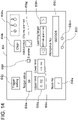
- the trigger setting input receiver 69 includes (a) a target value entry field 69a, which is for inputting a target dimension of a workpiece (a value indicated in the figure), (b) an upper limit entry field 69b and a lower limit entry field 69c, which are for inputting upper/lower tolerance limits, respectively, (c) 69e, which is an entry field for inputting block No., (d) 69f, which is checked when the target value and tolerance are in diameter, (e) 69g, which is a check column for initial product and chip exchange time, (f) a learning target axis entry field 69h, which is for inputting information for identifying an axis that is among the axes to move a movable member of the machine tool and that is a target axis for learning, (g) a workpiece number entry field 69i, which is for inputting a learning target workpiece, and (h) a trigger button 69n
- the trigger setting input receiver 69 further includes: a trigger setting button 69j, which is for setting (storing) input data; and a clear button 69k, which is for clearing (deleting) input data.
- the content set using the trigger setting input receiver 69 is effective through all machinings once the trigger setting button 69j is pressed. It is also possible to make a setting for each group of machined portions of a workpiece. For example, by switching between "1", “2", and "3" on the trigger button 69n, it is possible to set the above-described item data separately for a group made up of the machined portion having a diameter ⁇ of 35.0, the machined portion having a diameter ⁇ of 82.0, and the machined portion having a diameter ⁇ of 176.0, illustrated in FIG. 3 .
- the machining data collector 67 includes: a trigger information automatic collector 71, which automatically collects the machining data set at the trigger setting input receiver 69; and a trigger information memory storage 73, which stores trigger information in a memory.
- the trigger information automatic collector 71 automatically collects: the date and time when the machined portion set at the trigger setting input receiver was actually machined by the machine tool 1; and an offset. Then, the trigger information automatic collector 71 stores the collected information in the trigger information memory storage 73.
- offset is intended to mean data input by an operator. For example, if the accuracy with which the workpiece W is machined gradually degrades over time while the workpiece W is being machined, an offset can be forcibly implemented so that the dimension of the machined portion is secured within the tolerance range. It is possible to store this offset data and use this offset data to calculate an actual thermal displacement correction amount. Specifically, by adding this offset value, an accurate amount of thermal displacement correction can be calculated. Further, it is possible to input an offset after machining of a workpiece ends and before machining of a next workpiece starts. Thus, insofar as the machining accuracy of a workpiece W is monitored, implementing an offset eliminates or minimizes occurrence of a defective product in the machining performed at or after the offset.
- the dimension data input receiver 75 is a screen used in calculating the coefficient of the thermal displacement correction equation by machine learning. Specifically, dimension measurement data obtained by measuring a post-machining dimension of a machined portion set as a learning target is collected and input on the dimension data input receiver 75 based on the setting of the trigger setting input receiver 69.
- the dimension data input receiver 75 is made up of any one of (1) to (3).
- a semi-automatic "machining dimension call-up screen GUI (external measurement) 77” which receives an input of a measurement result measured outside the machine tool.
- a “machining dimension call-up automatic (internal measurement) 79” which automatically calls up all dimension measurement data measured in the machine tool 1.
- a “machining dimension manually input GUI 81” which receives a manual input of all machining dimension measurement data associated with a learning target axis. It is to be noted that a machining dimension may not necessarily be obtained by measuring a workpiece itself.
- the learning data generation/generation result display 83 generates learning data by comparing the machining data collected by the machining data collector 67 with the dimension measurement data collected and input by the dimension data input receiver 75 (learning data generator 85). Then, the learning data generation/generation result display 83 displays the generated result on the generation result display 87.
- the learning condition setter 89 sets, on a learning weight setting screen 91, a learning weight to the machined portion selected on a learning target selection screen 93.
- the machine learning executor 95 causes a correction coefficient calculator 97 to execute a machine learning based on the learning data and calculate a correction coefficient in a thermal displacement correction equation, which is used to correct a displacement caused by a change in the temperature of the machine tool 1.
- the learning result display/executor 99 displays a simulation graph of pre-machine learning and post-machine learning results on the estimated value display 103. As described later, when a post-machine learning simulation result is satisfactory, a user presses a learning result application button 101 to cause the memory rewriting instructor 105 to rewrite the thermal displacement correction equation stored in the thermal displacement correction equation memory 41 with the post-machine learning correction coefficient.
- the user may re-set a learning weight and/or a learning target, thus repeating a machine learning until a satisfactory simulation result is obtained.
- This ensures a correction coefficient used in a thermal displacement correction equation for a thermal displacement correction suitable for an environment in which a machine tool is provided.
- the trigger information automatic collector 71 collects machining data based on the content selected at the trigger setting input receiver 69.
- the trigger setting input receiver 69 includes, for example: the target value entry field 69a; an upper limit tolerance entry field 69b; a lower limit tolerance entry field 69c; a block No. entry field 69e, which is for inputting a block No. indicating a machining target portion in a workpiece machining program; the column 69f, which is a check column for workpiece diameter; the column 69g, which is a check column for initial product and chip exchange; the learning target axis entry field 69h, which is for inputting information for identifying a learning target axis; and the workpiece number entry field 69i, which is for inputting workpiece number.
- the trigger setting input receiver 69 further includes: the trigger setting button 69j, which is for setting (storing) input data; and the clear button 69k, which is for clearing (deleting) input data.
- the above-described items include at least one of: machining program number; and information for identifying a learning target axis. This makes it easier for the operator to select a machining target portion to which the operator wants to pay special attention, such as a portion of strict tolerance. As a result, a learning target can be determined accurately. This ensures a correction coefficient used in a thermal displacement correction equation for a thermal displacement correction suitable for an environment in which a machine tool is provided.
- the controller or the machine tool according to this embodiment makes it easier to select a particular step, which normally takes much more time. As a result, machining data necessary for machine learning is efficiently collected.
- the trigger information collected at step S01 and stored in a memory has a file layout as illustrated in FIG. 6 , for example. Specifically, the date and time when the machined portion corresponding to the trigger information is machined by the machine tool 1 are first stored as machining data. Subsequently to the date and time data, next various data are stored in a memory.
- Trigger# is a number assigned to a machined portion of a workpiece. When "1" is assigned to the initial product, this indicates that a tool exchange has been performed. When "0" is assigned to the initial product, this indicates that no tool exchange is performed.
- Target value is a target dimension of machining. Offset is the amount of movement of the cutting edge input by the operator. Upper limit and Lower limit are those of tolerance.
- Learning target is information for identifying an axis that is among the axes to move a movable member of the machine tool and that is a learning target axis (for example, "HD1 Y axis upper tool rest” indicates the Y axis for machining the workpiece at the first workpiece spindle side using upper tool rest).
- Workpiece No. is information for identifying a machining program.
- various machining data are stored in one row in a file so that the data are correlated with each other.
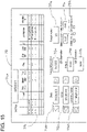
- FIG. 15 illustrates an example input receiver on which information such as machining dimension are manually input.
- This input receiver includes: a workpiece number entry field 75a, which is for inputting workpiece number; a date entry field 75b, which is for inputting date of machining; a machining time entry field 75c, which is for inputting time of machining; a learning target axis entry field 75d, which is for inputting information for identifying a learning target axis; a measurement value entry field 75e, which is for inputting a measurement value; an offset entry field 75f, which is for inputting an offset; a target value entry field 75g, which is for inputting a workpiece target value; an upper limit tolerance entry field 75h, which is for inputting an upper limit tolerance; and a lower limit tolerance entry field 75i, which is for inputting a lower limit tolerance. It is to be noted that all the entry fields excluding the measurement value entry field are automatically filled
- data such as the data illustrated in FIG. 7 is used, for example.
- the dimension data input receiver 75 includes a window 751. By pressing an input button 75j, all the input dimension data are displayed in the window 751.
- the window 751 is scrollable.
- the input items included in the dimension data input receiver will not be limited to the above-described input items; any other input items are possible insofar as they enable the operator to determine which machining data an actual machining dimension and the associated machining correspond to.
- FIG. 15 illustrates a manual input screen
- this input screen is not intended in a limiting sense.
- a possible input screen is that an item for identifying machining dimension data to call up can be input. For example, it is possible to obtain necessary machining dimension data only by identifying the date and time of machining and a dimension measurement position.
- machining dimension measurement data possible methods are: calling up externally measured machining dimension measurement data; automatically calling up internally measured machining dimension measurement data; and manually inputting machining dimension measurement data.
- the controller or the machine tool according to this embodiment is capable of measuring machining dimension measurement data by these various methods. This configuration ensures that a suitable method can be freely selected based on machining dimension characteristics and/or a purpose of adjustment. This configuration also provides a design significantly easily handleable for the operator of the machine tool.
- machining dimension data it is possible to employ either of the following methods: a method that sets a target item including a learning target and then collects dimension data of a particular machined portion corresponding to the target item that has been set; and a method that obtains all machining dimension data in advance and extracts a piece of machining dimension data that is selected from the all machining dimension data and that corresponds to the target item.
- a method that sets a target item including a learning target and then collects dimension data of a particular machined portion corresponding to the target item that has been set and a method that obtains all machining dimension data in advance and extracts a piece of machining dimension data that is selected from the all machining dimension data and that corresponds to the target item.
- the learning data generation/generation result display 83 integrates the machining data collected by the machining data collector 67 with the dimension data specified by the dimension data input receiver 75. As a result, learning data actually used in machine learning is identified. It is to be noted, however, that in a case of manual input, the integration processing is performed at the time of manual input.
- the generation result display 87 illustrated in FIG. 2 displays a content as illustrated in, for example, FIG. 8 .
- the content includes, from left, the date and time of machining, trigger#, initial product, measurement value, target value, offset, upper limit tolerance, lower limit tolerance, indication or non-indication of diameter, information for identifying a learning target axis, and workpiece number.
- the generation result display 87 displays a list of these integrated data. This ensures that input values of workpiece numbers can be easily compared with each other by rearranging the corresponding data. As a result, even if the operator makes an erroneous input, the erroneous input can be easily identified.
- the data collected at step S05 and stored in a memory has a file layout as illustrated in FIG. 8 , for example.
- the trigger information is generated by integrating the dimension data based on the date and time of machining
- the learning data includes the following various data.
- Trigger# is a number assigned to a machined portion of a workpiece. When "1" is assigned to the initial product, this indicates that a tool exchange has been performed.
- Measurement value is dimension data that has been measured.
- Target value is a target dimension of machining. Offset is the amount of movement of the cutting edge input by the operator. Upper limit and Lower limit are those of tolerance.
- ⁇ is 1, the data value is in diameter.
- Learning target is information for identifying a learning target axis.
- Workpiece No. is information for identifying a machining program. Thus, various machining data are stored in one row in a file so that the data are correlated with each other.
- the learning data generation/generation result display 83 determines whether there is a data mismatch between the machining data collected by the machining data collector 67 and the machining dimension data specified by the dimension data input receiver 75.
- the procedure goes back to step S03, where a re-input of dimension data is demanded.
- the procedure proceeds to step S09.
- the learning condition setter 89 sets a learning condition. Specifically, the learning condition setter 89 selects a machined portion of the workpiece as a learning target, and determines a learning weight condition.
- a learning weight condition can be set on an individual-machined-portion basis. For example, there may be a machining target portion that is among a plurality of machining target portions and that is desired to be prioritized over other machining target portions in increasing machining accuracy. In this case, a learning weight condition can be set on this machining target portion. This ensures a correction coefficient used in a thermal displacement correction equation for a thermal displacement correction suitable for an environment in which a machine tool is provided.
- the machine learning executor 95 performs a machine learning (regression analysis) with the selection at step S09 taken into consideration.
- the machine learning executor 95 reads (1) learning function data ⁇ , which is stored in the memory 39. Also, the machine learning executor 95 reads (2) a thermal displacement estimation log, which is thermal displacement correction data at the actual machining time. Further, the machine learning executor 95 reads (3) a temperature log, which has been detected and stored at predetermined intervals.
- the learning function data ⁇ is learning data used when the current correction coefficient was calculated. It is to be noted, however, that the (1) data is not essential data, and may be omitted.
- thermal displacement correction log Data read as the thermal displacement correction log subsequently to the date and time when the workpiece was machined are movement position data of tool rests such as the X axis upper tool rest, the Y axis upper tool rest, and the Z axis upper tool rest.
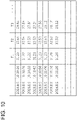
- FIG. 10 an example temperature log will be described.
- the temperature log is such that temperatures at the temperature sensors T1 to T6 are read at, for example, 10-second intervals, and each temperature is stored in correlation with the date and time of reading. This ensures that the X axis upper tool rest, the Y axis upper tool rest, and the Z axis upper tool rest corresponding to a date and time can be correlated with the temperature corresponding to the same date and time.
- the machine learning executor 95 reads learning data.
- learning data is intended to mean machining dimension data specified by the learning data generation/generation result display 83.
- the machine learning executor 95 reads a learning weight condition.
- learning weight condition is intended to mean a condition for which the number of data of a particular learning target regarded as important is increased when one workpiece is machined, so as to set a weight given to the learning target.
- the thermal displacement correction as a whole can be adjusted by prioritizing the accuracy of an important portion of a machining target workpiece over the accuracy of another portion of the workpiece.
- the machining accuracy of a workpiece as a whole can be set within a desired range. This ensures a correction coefficient used in a thermal displacement correction equation for a thermal displacement correction suitable for an environment in which a machine tool is provided.
- the level of weighting can be selected from five levels. At level five, which is the highest level, the number of data of a weighting target may be increased by, for example, 50 times, after which the data may be reflected in the thermal displacement correction as a whole.
- the machine learning executor 95 converts the learning data into "no-thermal-displacement-correction data".
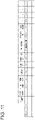
- the machine learning executor 95 performs processing of converting the measurement value that is included in the learning data read at step S15 and that is illustrated in, for example, FIG. 11 into dimension data that is for a case where no correction was made and that is illustrated in, for example, FIG. 12 .
- Trigger# is a number assigned to a machined portion of a workpiece. When "1" is assigned to the initial product, this indicates that a tool exchange has been performed.
- Measurement value is dimension data that has been measured.
- Target value is a target dimension of machining.
- Offset is the amount of movement of the cutting edge input by the operator. Upper limit and Lower limit are those of tolerance.
- ⁇ is 1, the data value is in diameter.
- Learning target is information for identifying a learning target axis.
- Workpiece No. is information for identifying a machining program. Correction amount is a correction position on the tool cutting edge.
- Temperature data is such that a temperature at a date and time of machining is stored. Thus, various machining data are stored in one row in a file so that the data are correlated with each other.
- the data illustrated in FIG. 12 is such that the measurement value included in the data illustrated in FIG. 11 is replaced with dimension data for a case where no correction was made. Otherwise, the data illustrated in FIGs. 11 and 12 are identical.
- the dimension data input into the dimension data input receiver 75 is a result of a past thermal displacement correction already performed. Under the circumstances, in order to perform a new machine learning, it is necessary to: remove the influence of the thermal displacement correction to retrieve the state in which no thermal displacement correction was performed; and reflect a result of a new machine learning.
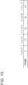
- the machine learning executor 95 extracts, based on the setting made at the learning condition setter 89, a "weight" for the learning data from a weight table.
- weighting is to: extract 5 as a weight at LeveL 1; extract 10 as a weight at LeveL 2; extract 20 as a weight at LeveL 3; extract 35 as a weight at LeveL 4; and extract 50 as a weight at LeveL 5.
- weight values indicate that the number of data of interest is increased by adding a number of data corresponding to a weight value, after which a re-calculation is performed. This indicates that as the weight becomes greater, the number of data increases, and this increases the influence on the correction amount.
- the machine learning executor 95 increases the amount of the "no-thermal-displacement-correction data" by an amount equivalent to the weight.
- the machine learning executor 95 adds the increased "no-thermal-displacement-correction data" and the learning function data ⁇ together, and then obtains a new correction coefficient by solving an inverse matrix.
- the learning function data ⁇ and data obtained during an actual machining are stored.
- the learning function data ⁇ is stored in the memory 39, and the actual machining data is stored in the temperature logger 31 and the thermal displacement estimated amount logger 45.
- the learning function data ⁇ which is stored in the memory 39, includes temperature matrix ( ⁇ ) and thermal displacement amount matrix ( y ).
- temperature matrix a number of pieces of temperature data equal to the number of samples are arranged in the vertical direction, and measurement values corresponding to the respective temperature sensors are arranged in the lateral direction.
- thermal displacement amount matrix a number of pieces of displacement data equal to the number of samples are arranged in the vertical direction.
- Equation 2 A regression analysis is performed and the correction coefficient ( ⁇ ) is obtained by solving Equation 2 so that the thermal displacement correction amount matrix ( yc ) is as close as possible to the thermal displacement amount matrix ( y ).
- ⁇ ' denotes a transposed matrix of ⁇ .
- the correction coefficient ( ⁇ ) thus obtained is regarded as an original (pre-learning) correction coefficient.
- ⁇ ⁇ ′ ⁇ ⁇ ⁇ 1 ⁇ ⁇ ′ ⁇ y
- the left side matrix which is temperature data in the case of performing actual machining
- the right side matrix which is the thermal displacement amount
- ⁇ ' ⁇ and ⁇ 'Y which are products obtained from multiplications using the transposed matrix ⁇ ' of ⁇ , are added to the original data that is stored. Then, the resulting sum is multiplied by an inverse matrix. As a result, a post-learning, new correction coefficient ⁇ _new is obtained.
- ⁇ _ new ⁇ ′ ⁇ ⁇ + ⁇ ′ ⁇ ⁇ ⁇ 1 ⁇ ⁇ ′ ⁇ y + ⁇ ′ ⁇ Y
- the learning result display/executor 99 displays, on the estimated value display 103, a simulation graph obtained using the new correction coefficient.
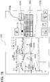
- FIG. 16 illustrates an example simulation graph displayed on the estimated value display 103.
- the simulation graph shows simulations results associated with three kinds of workpiece numbers, namely, "W0001", “W0002”, “W0003".
- the workpiece number "W0001" is a simulation graph associated with a left portion 103d
- the workpiece number "W0002” is a simulation graph associated with a middle portion 103e
- the workpiece number "W0003” is a simulation graph associated with a right portion 103f.
- data 103a which is indicated by symbol " ⁇ " is data in a case where no correction was performed
- data 103b which is indicated by a black filled circle, is data of a measurement result obtained by the operator
- data 103c which is indicated by a white-background square outline, is data of a result in a case where the new correction coefficient was used.
- the controller or the machine tool displays, for all machining target portions that have been specified, a simulation graph of estimated values associated with a machining performed using a post-learning correction coefficient.
- machining results associated with three workpiece numbers are displayed at a time. This enables the operator to check whether all the machining results are kept within a desired tolerance.
- estimated values associated with a plurality of machining target portions are displayed simultaneously. This manner of display enables the operator to easily visually check how the machining accuracy at each portion changes and whether a necessary tolerance is secured. This ensures a correction coefficient used in a thermal displacement correction equation for a thermal displacement correction suitable for an environment in which a machine tool is provided.
- the operator makes a determination as to whether a simulation result shows a sufficient level of machining accuracy.
- the operator sets the learning level to, for example, a heavy level using a learning level setting column 103g illustrated in FIG. 16 .
- the operator presses a learning button 103h to return the learning level processing to step S09.
- the operator may repeat this operation until the operator determines that a sufficient level of machining accuracy is secured, with the result data kept within the tolerance range.
- step S31 When the operator has determined that the simulation result shows a sufficient level of machining accuracy, the procedure proceeds to step S31.
- step S31 the operator presses a memory rewriting execution button 103j to rewrite the content of the thermal displacement correction equation memory 41 of the memory 39 illustrated in FIG. 2 .
- the dimension data may be processed through the following steps.
- This method ensures that from the start of learning, necessary data can be selected from all the learning data accumulated.
- buttons 691 and 69m illustrated in FIG. 14 are switchable using buttons 691 and 69m illustrated in FIG. 14 .
- the data of the machining data and/or the correction parameter used in this embodiment may be transferred to a controller and/or a machine tool that are similar in kind to the controller and/or the machine tool according to this embodiment. That is, a result obtained in one apparatus (device) may be shared with a similar kind of apparatus (device) that operates under similar conditions. Thus, data may be horizontally expanded. This effectively increases the operation efficiency with which a plurality of similar apparatuses (devices) are operated.
- the operator only has to select an item that requires a machining accuracy (an example item is a machining program number) and press the machine learning execution button. In this manner, the operator is able to obtain a simulation result based on machining data. Additionally, the operator is able to visually check, in the form of a list, results for all machined portions that the operator desires to check. This enables the operator to easily determine whether each portion is kept within a specified tolerance.
- controller or the machine tool performs a learning of all machined portions collectively, and sets a correction coefficient that satisfies all the machined portions. This reduces the occurrence of a result showing a deviation from the target dimension.
- a learning level of machine learning can be set based on the degree of importance on a workpiece basis or on a workpiece-machined-portion basis, and a learning of a plurality of workpieces is performed collectively. This reduces the labor involved in adjustment work and ensures that fine adjustments are easily performed. Also, there may be a case where it is necessary to manually set a thermal displacement correction amount that varies on an individual-machined-portion basis. In this case, if there is a large difference between the thermal displacement correction amounts set for the machined portions, a stepped machined surface may occur at a portion where adjacent machined portions abut. This issue is dealt with by the configuration of the above-described embodiment, in which a correction coefficient is automatically set by selecting a machined portion. This configuration eliminates or minimizes erroneous setting due to human error, preventing such a situation in which a stepped machined surface occurs.
- section termed as function section may be implemented by a CPU including a storage device such as a memory and software introduced in these elements, or may be implemented by an electronic circuit, a logic circuit, and/or other related devices.
- section termed as display may be implemented by a screen, or the data input-output function of the display may be implemented by a sensor.
- controller and/or the machine tool according to the above-described embodiment may also be applied to a lathe, a machining apparatus, and a discharge machining apparatus, among other apparatuses or devices.
- Reference Signs List
Landscapes
- Engineering & Computer Science (AREA)
- Physics & Mathematics (AREA)
- General Physics & Mathematics (AREA)
- Automation & Control Theory (AREA)
- Human Computer Interaction (AREA)
- Manufacturing & Machinery (AREA)
- Artificial Intelligence (AREA)
- Software Systems (AREA)
- Mechanical Engineering (AREA)
- Evolutionary Computation (AREA)
- Computer Vision & Pattern Recognition (AREA)
- Medical Informatics (AREA)
- Theoretical Computer Science (AREA)
- Health & Medical Sciences (AREA)
- Data Mining & Analysis (AREA)
- Computing Systems (AREA)
- General Engineering & Computer Science (AREA)
- Mathematical Physics (AREA)
- Automatic Control Of Machine Tools (AREA)
- Numerical Control (AREA)
Abstract
Description
- The present invention relates to a controller, a machine tool, a calculation method, and a program.
- Components of a machine tool undergo thermal expansion due to heat generated by operating the machine tool and external heat around the machine tool. Thermal expansion is known to cause an error in the positioning between the cutting edge of a tool and a workpiece machined, to the detriment of the accuracy with which a machine tool machines a workpiece. Such thermal expansion-caused degradation in the accuracy of the positioning between the cutting edge of a tool and a workpiece machined is referred to as thermal displacement.
- In light of thermal expansion considerations, some numerical controllers (hereinafter referred to as "controller(s)") for controlling machine tools have a function to correct thermal displacement. In this case, a thermal displacement correcting function employed is implemented by: providing each of main components constituting a machine tool with a temperature sensor; multiplying the temperature of each component by a coefficient; obtaining a sum of the values obtained by the multiplications; and regarding the sum as the amount of thermal displacement correction.
- There are, however, a large number of heat sources that can cause thermal displacement, and it is not easy to correct a thermal displacement accurately.
-
Patent literature 1 discloses a machine tool that includes a thermal displacement correction amount setting changer provided with a plurality of temperature sensors mounted on components constituting the machine tool. Based on temperatures from the plurality of temperature sensors, the machine tool estimates a drive-system thermal displacement amount and an environment temperature-system thermal displacement amount. Then, the machine tool subjects these amounts to correction magnification processing and adds the resulting values of the amounts together. In this manner, the machine tool calculates the total amount of thermal displacement correction. - PTL1:
JP6001211B1 - It is an object of the present invention to provide a controller, a machine tool, a calculation method, and a program that calculate a correction coefficient used in a thermal displacement correction equation for a thermal displacement correction suitable for an environment in which a machine tool is provided.
- In order to solve the above-described problem, a representative controller and a representative machine tool according to the present invention each include: a machining data collector configured to collect machining data including a date and a time when at least one machined portion that is a part of a workpiece and that was set as a learning target was machined by a machine tool; a temperature collector configured to collect, at predetermined time intervals, temperature data obtained at a plurality of positions on the machine tool; a dimension data input receiver configured to receive an input of dimension measurement data obtained by measuring a dimension of the at least one machined portion after the at least one machined portion has been machined; a learning data generator configured to generate learning data including the machining data and the dimension measurement data; and a machine learning executor configured to execute a machine learning based on the temperature data and the learning data, and configured to calculate a correction coefficient used in a thermal displacement correction equation for correcting a displacement caused by a change in a temperature of the machine tool.
- A representative calculation method according to the present invention includes: setting at least one machined portion of a workpiece as a learning target; collecting machining data including a date and a time when the at least one machined portion was machined by a machine tool; collecting, at predetermined time intervals, temperature data obtained at a plurality of positions on the machine tool; receiving an input of dimension measurement data obtained by measuring a dimension of the at least one machined portion after the at least one machined portion has been machined; generating learning data including the machining data and the dimension measurement data; and executing a machine learning based on the temperature data and the learning data, and calculating a correction coefficient used in a thermal displacement correction equation for correcting a displacement caused by a change in a temperature of the machine tool.
- Further, a representative program according to the present invention is a program for causing a computer to execute the above-described calculation method.
- The present invention provides a controller, a machine tool, a calculation method, and a program that calculate a correction coefficient used in a thermal displacement correction equation for a thermal displacement correction suitable for an environment in which a machine tool is provided. Problems, configurations, and effects other than those described above will become apparent from the following description of embodiments.
-
- [
FIG. 1] FIG. 1 is a perspective view of a configuration of a machine tool according to an embodiment. - [
FIG. 2] FIG. 2 is a block diagram of a controller provided in the machine tool according to the embodiment. - [
FIG. 3] FIG. 3 illustrates a relationship between machined portion and block No. - [
FIG. 4] FIG. 4 is a flowchart of how a learning function section operates. - [
FIG. 5] FIG. 5 is a flowchart of a learning calculation. - [
FIG. 6] FIG. 6 illustrates a file layout of trigger information. - [
FIG. 7] FIG. 7 illustrates a file layout of dimension data. - [
FIG. 8] FIG. 8 illustrates a file layout of integrated data. - [
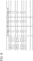
FIG. 9] FIG. 9 illustrates a file layout of a thermal displacement correction log. - [
FIG. 10] FIG. 10 illustrates a file layout of a temperature log. - [
FIG. 11] FIG. 11 illustrates a file layout of correction-including dimension data in learning data. - [
FIG. 12] FIG. 12 illustrates a file layout of no-correction dimension data in the learning data. - [
FIG. 13] FIG. 13 illustrates a file layout of a learning weight. - [
FIG. 14] FIG. 14 is a diagram illustrating an example trigger setting input receiver. - [
FIG. 15] FIG. 15 is a diagram illustrating an example dimension data input receiver (where machining dimensions are manually input). - [
FIG. 16] FIG. 16 illustrates an estimated value display. - Embodiments of the present invention will be described by referring to the accompanying drawings.
-
FIG. 1 illustrates a main configuration of amachine tool 1 according to this embodiment. The machine tool according to this embodiment includes: a workpiece holder that holds a workpiece; and a tool holder that holds a tool. With this configuration, the machine tool machines the workpiece using the tool by rotating at least one of the workpiece and the tool and moving at least one of the workpiece and the tool in a predetermined direction. - The machine tool also includes a plurality of temperature sensors mounted on components constituting the machine tool.
- Specifically, the
machine tool 1 includes: abed 3; afirst workpiece headstock 5, which is fixed to thebed 3; afirst workpiece spindle 7, which is mounted on thefirst workpiece headstock 5 and rotatable in C axis direction; acarriage base 18, which is a movable member movable on thebed 3 along Y axis direction and Z axis direction; acarriage 9, which is placed on thecarriage base 18; asaddle 10, which is a movable member movable on thecarriage 9 along X axis direction; atool headstock 11, which is mounted on thesaddle 10 and swingable along B axis direction; atool spindle 13, which is a rotatable tool holder mounted on thetool headstock 11; and acontroller 23, which controls these components. - It is to be noted that X axis, Y axis, and Z axis are regarded as axes along which a movable member moves. It is also to be noted that B axis is intended to mean a movement axis of the
tool spindle 13 in the direction in which thetool spindle 13 rotates about the Y axis, and that the C axis is intended to mean a movement axis of thefirst workpiece spindle 7 or asecond workpiece spindle 19 in the direction in which the first workpiece spindle 7 or thesecond workpiece spindle 19 rotates about the Z axis. - A tool TL is attached to the
tool spindle 13, and a workpiece W1 is attached to achuck 15, which is a workpiece holder mounted on thefirst workpiece spindle 7. With the tool TL and the workpiece W1 in this arrangement, the workpiece W1 is machined using the tool TL. - The
machine tool 1 further includes asecond workpiece headstock 17, which is movable on thebed 3 along the Z axis direction. Thesecond workpiece headstock 17 includes thesecond workpiece spindle 19, which is rotatable along the C axis direction. A workpiece W2 is attached to achuck 21, which is a workpiece holder mounted on thesecond workpiece spindle 19. With the workpiece W2 in this arrangement, the workpiece W2 is machined using the tool TL as well. - It is to be noted that while the
tool spindle 13 of themachine tool 1 illustrated inFIG. 1 has a configuration of an upper tool rest, thetool spindle 13 may have a configuration of a lower tool rest in addition to a configuration of an upper tool rest. - As illustrated in
FIG. 1 , temperature sensors T1 to T6 are mounted on the above-described components of the machine tool 1 (the temperature sensors are indicated by dots or broken line circles inFIG. 1 ). Specifically, the temperature sensor T1 is mounted on thetool headstock 11. The temperature sensor T2 is mounted on thecarriage 9. The temperature sensor T3 is mounted on thecarriage base 18. The temperature sensor T4 is mounted on thefirst workpiece headstock 5. The temperature sensor T5 is mounted on thebed 3 at or near its center portion immediately under the machining region, considering that the center portion is greatly affected by heating involved in cutting. The temperature sensor T6 is mounted on thesecond workpiece headstock 17. - Thus, the temperature sensors T1 to T6 are respectively mounted on the
tool headstock 11, thecarriage 9, thecarriage base 18, thefirst workpiece headstock 5, thebed 3, and thesecond workpiece headstock 17. This arrangement ensures that not only temperatures at particular positions on themachine tool 1 but also temperatures at various other positions on themachine tool 1 are measured. - It is to be noted that when the number of temperature sensors that the machine tool includes is n, the amount of thermal displacement correction for the cutting edge can be calculated by solving the Formula shown below for each of the X axis, the Y axis, and the Z axis. It is to be noted that for purposes of illustration, only a single Formula for calculating the amount of thermal displacement correction is shown, and that in actual situations, three correction equations are solved to calculate the amounts of thermal displacement correction for the X axis, the Y axis, and the Z axis.

- The amount of thermal displacement correction thus calculated is added to position commands transmitted to an
X axis motor 59, aY axis motor 61, and aZ axis motor 63, which are mounted on predetermined components. In this manner, the movement of the cutting edge is corrected. - As can be seen from the above description, to automatically calculate an appropriate amount of thermal displacement correction for a machine tool means to automatically calculate the correction coefficients a1 to an in the above-described equation so that an appropriate amount of thermal displacement correction is calculated.
- As illustrated in
FIG. 1 , thecontroller 23 of themachine tool 1 is communicably connected to themachine tool 1. The communication between thecontroller 23 and themachine tool 1 may be made through acable 27 or using another communication means such as wireless communication. Thecontroller 23 is implemented by a computer, another information processing device, and a storage device, and includes elements such as a CPU, a RAM, and a ROM, not illustrated. - A
display 25 may be mounted on thecontroller 23 or in the form of a structure separate from thecontroller 23. Thedisplay 25 may also serve as a trigger settinginput receiver 69, a learning data generation/generation result display 83, ageneration result display 87, and an estimatedvalue display 103, which are illustrated inFIG. 2 . Thedisplay 25 is also capable of displaying various kinds of data and serving as an input-output device. Therefore, thedisplay 25 may also serve as the trigger settinginput receiver 69 and a dimensiondata input receiver 75. For example, thedisplay 25 may be implemented in the form of a touch panel on which an input and an output are made. -
FIG. 2 is a diagram illustrating a hardware configuration of thecontroller 23, which is provided in themachine tool 1. - The
controller 23 includes: atemperature collector 29, which is associated with the temperature sensors T1 to T6; a thermal displacementcorrection amount estimator 33; amemory 39, which is made up of elements such as an SRAM; a thermal displacement estimatedamount logger 45; and acommander 47. - The
temperature collector 29 includes atemperature logger 31. At predetermined time intervals (for example, 10-second intervals), thetemperature collector 29 collects and stores temperature data of a plurality of positions on themachine tool 1 from the temperature sensors T1 to T6. - The thermal displacement
correction amount estimator 33 reads a correction equation from a thermal displacementcorrection equation memory 41, which is stored in thememory 39. Then, the thermal displacementcorrection amount estimator 33 calculates a thermal displacement correction amount by solving this correction equation. - The thermal displacement estimated
amount logger 45 stores the value of the thermal displacement correction amount obtained at the thermal displacementcorrection amount estimator 33. - The
commander 47 outputs: a movement command indicating a correction amount X 51, which is for the X axis; a movement command indicating a correction amount Y53, which is for the Y axis; and a movement command indicating a correction amount Z55, which is for the Z axis. - The
machine tool 1 also includes a thermal displacementcorrection motion executor 57. The thermal displacementcorrection motion executor 57 adds the above-described correction amounts to the respective position commands for the X, Y, and Z axes, and causes theX axis motor 59, theY axis motor 61, and theZ axis motor 63 to move the cutting edge in the X, Y, and Z axes by amounts indicated by the position commands. Each of theX axis motor 59, theY axis motor 61, and theZ axis motor 63 is made up of a servo motor, for example. With the configuration described above, the workpiece W1 is machined into proper dimensions within a tolerance range. - A
learning function section 65 includes amachining data collector 67, the dimensiondata input receiver 75, the learning data generation/generation result display 83, alearning condition setter 89, amachine learning executor 95, a learning result display/executor 99, and amemory rewriting instructor 105. - The
machining data collector 67 is a function section for selecting machining data (log data) that is to be subjected to machine learning. For this purpose, in order to identify the kind of log data to collect, it is necessary at themachining data collector 67 to set, as a learning target, items such as: information for identifying an axis along which to move a movable member of the machine tool; and a machined portion. The trigger settinginput receiver 69 is an input receiver for identifying such collection data. - In light of this necessity, the following items can be specified at the trigger setting input receiver 69: (1) information concerning initial product and chip exchange, (2) specification of diameter/radius, (3) target value, (4) upper tolerance limit, (5) lower tolerance limit, (6) learning target position (for example, "upper tool rest of first workpiece spindle X axis"), (7) workpiece No. (workpiece number), (8) trigger No. (trigger number), and (9) block No. (block number). Among these items, (7) workpiece No. is information for identifying a machining program, and (9) block No. is a number indicating a command position of an individual machined portion in the machining program. Thus, workpiece No. and block No. are data used later for specifying a machined portion and calculating a thermal displacement correction amount. For example, temperatures are automatically measured at predetermined time intervals at the temperature sensors T1 to T6 (which are provided at predetermined positions on the machine tool 1) and are stored in correlation with measurement times. Also, the date and time when the current workpiece was machined are input, ensuring that the temperature at the machining time can be checked. Then, by inputting dimension measurement data at the actual machining time, a difference between the target dimension and the actual dimension can be calculated. Then, by correlating the difference with the temperatures measured at the temperature sensors T1 to T6, which are provided on the
machine tool 1, learning data can be obtained. It is to be noted that the dimension measurement data difference may be calculated based on an initial product dimension. - By referring to
FIG. 3 , a relationship between a machined portion and block No. will be described.FIG. 3 illustrates a cross-section of a part of a final product obtained by machining the workpiece W using themachine tool 1. The workpiece W exemplified here has a cylindrical portion having a diameter φ of 176.0, a cylindrical portion having a diameter φ of 120.0, a cylindrical portion having a diameter φ of 82.0, and a cylindrical portion having a diameter φ of 35.0. Adjacent cylindrical portions are connected to each other by a continuous inclined surface. Block Nos. indicate portions of the workpiece W represented by numbers starting with "N" inFIG. 3 , namely, N001 to N018. Using a block No. facilitates the identification of a command position of an individual machined portion in the machining program in machining the workpiece W. For example, the command for machining the cylindrical portion having a diameter φ of 176.0 is described in block No. "N013", the command for machining the cylindrical portion having a diameter φ of 82.0 is described in "N009", and the command for machining the cylindrical portion having a diameter φ of 35.0 is described in "N007". Incidentally, in some cases, it is necessary to identify a machined portion where a high level of accuracy is required in conforming with tolerance and to machine this machined portion with a higher level of accuracy. In this example, the machined portion having a diameter φ of 35.0 and the machined portion having a diameter φ of 82.0 will be assumed as corresponding to such machined portion. In this case, block Nos. "N007" and "N009" are used to set, as learning targets, these machined portions where a high level of accuracy is required in conforming with tolerance. That is, a machined portion can be specified by a number indicating a position in the machining program. - A specific example of the trigger setting
input receiver 69 is illustrated inFIG. 14 . The trigger settinginput receiver 69 includes (a) a targetvalue entry field 69a, which is for inputting a target dimension of a workpiece (a value indicated in the figure), (b) an upperlimit entry field 69b and a lowerlimit entry field 69c, which are for inputting upper/lower tolerance limits, respectively, (c) 69e, which is an entry field for inputting block No., (d) 69f, which is checked when the target value and tolerance are in diameter, (e) 69g, which is a check column for initial product and chip exchange time, (f) a learning targetaxis entry field 69h, which is for inputting information for identifying an axis that is among the axes to move a movable member of the machine tool and that is a target axis for learning, (g) a workpiecenumber entry field 69i, which is for inputting a learning target workpiece, and (h) atrigger button 69n, which is for specifying trigger number. There are three different kinds of trigger setting; by selecting "1", "2", or "3" on thetrigger button 69n, the trigger setting can be switched between the three different kinds. - The trigger setting
input receiver 69 further includes: atrigger setting button 69j, which is for setting (storing) input data; and aclear button 69k, which is for clearing (deleting) input data. - It is to be noted that the content set using the trigger setting
input receiver 69 is effective through all machinings once thetrigger setting button 69j is pressed. It is also possible to make a setting for each group of machined portions of a workpiece. For example, by switching between "1", "2", and "3" on thetrigger button 69n, it is possible to set the above-described item data separately for a group made up of the machined portion having a diameter φ of 35.0, the machined portion having a diameter φ of 82.0, and the machined portion having a diameter φ of 176.0, illustrated inFIG. 3 . In this case, if the machined portion having a diameter φ of 35.0 and the machined portion having a diameter φ of 82.0 have important dimensions, it is possible to set a greater learning weight, described later, for the machined portions. This increases the efficacy of the amount of thermal displacement correction. - The
machining data collector 67 includes: a trigger informationautomatic collector 71, which automatically collects the machining data set at the trigger settinginput receiver 69; and a triggerinformation memory storage 73, which stores trigger information in a memory. - The trigger information
automatic collector 71 automatically collects: the date and time when the machined portion set at the trigger setting input receiver was actually machined by themachine tool 1; and an offset. Then, the trigger informationautomatic collector 71 stores the collected information in the triggerinformation memory storage 73. - An offset will be described. As used herein, the term "offset" is intended to mean data input by an operator. For example, if the accuracy with which the workpiece W is machined gradually degrades over time while the workpiece W is being machined, an offset can be forcibly implemented so that the dimension of the machined portion is secured within the tolerance range. It is possible to store this offset data and use this offset data to calculate an actual thermal displacement correction amount. Specifically, by adding this offset value, an accurate amount of thermal displacement correction can be calculated. Further, it is possible to input an offset after machining of a workpiece ends and before machining of a next workpiece starts. Thus, insofar as the machining accuracy of a workpiece W is monitored, implementing an offset eliminates or minimizes occurrence of a defective product in the machining performed at or after the offset.
- The dimension
data input receiver 75 is a screen used in calculating the coefficient of the thermal displacement correction equation by machine learning. Specifically, dimension measurement data obtained by measuring a post-machining dimension of a machined portion set as a learning target is collected and input on the dimensiondata input receiver 75 based on the setting of the trigger settinginput receiver 69. - The dimension
data input receiver 75 is made up of any one of (1) to (3). (1) A semi-automatic "machining dimension call-up screen GUI (external measurement) 77", which receives an input of a measurement result measured outside the machine tool. (2) A "machining dimension call-up automatic (internal measurement) 79", which automatically calls up all dimension measurement data measured in themachine tool 1. (3) A "machining dimension manually inputGUI 81", which receives a manual input of all machining dimension measurement data associated with a learning target axis. It is to be noted that a machining dimension may not necessarily be obtained by measuring a workpiece itself. - It is possible to: attach a touch sensor to the
tool spindle 13 illustrated inFIG. 1 ; measure, using the touch sensor, a change in a coordinate of a predetermined position on themachine tool 1; and regard the measured change as dimension measurement data. - The learning data generation/
generation result display 83 generates learning data by comparing the machining data collected by themachining data collector 67 with the dimension measurement data collected and input by the dimension data input receiver 75 (learning data generator 85). Then, the learning data generation/generation result display 83 displays the generated result on thegeneration result display 87. - The
learning condition setter 89 sets, on a learningweight setting screen 91, a learning weight to the machined portion selected on a learningtarget selection screen 93. - The
machine learning executor 95 causes acorrection coefficient calculator 97 to execute a machine learning based on the learning data and calculate a correction coefficient in a thermal displacement correction equation, which is used to correct a displacement caused by a change in the temperature of themachine tool 1. - Processings performed by the
learning condition setter 89 and themachine learning executor 95 will be described later in "Operation of Learning Function Section". - The learning result display/
executor 99 displays a simulation graph of pre-machine learning and post-machine learning results on the estimatedvalue display 103. As described later, when a post-machine learning simulation result is satisfactory, a user presses a learningresult application button 101 to cause thememory rewriting instructor 105 to rewrite the thermal displacement correction equation stored in the thermal displacementcorrection equation memory 41 with the post-machine learning correction coefficient. - When, in contrast, the post-machine learning simulation result is unsatisfactory, the user may re-set a learning weight and/or a learning target, thus repeating a machine learning until a satisfactory simulation result is obtained. This ensures a correction coefficient used in a thermal displacement correction equation for a thermal displacement correction suitable for an environment in which a machine tool is provided.
- Next, an operation of the
learning function section 65 will be described by referring to the flowcharts illustrated inFIGs. 4 and5 . - As illustrated in
FIG. 4 , at step S01, the trigger informationautomatic collector 71 collects machining data based on the content selected at the trigger settinginput receiver 69. - As illustrated in
FIG. 14 , the trigger settinginput receiver 69 includes, for example: the targetvalue entry field 69a; an upper limittolerance entry field 69b; a lower limittolerance entry field 69c; a blockNo. entry field 69e, which is for inputting a block No. indicating a machining target portion in a workpiece machining program; thecolumn 69f, which is a check column for workpiece diameter; thecolumn 69g, which is a check column for initial product and chip exchange; the learning targetaxis entry field 69h, which is for inputting information for identifying a learning target axis; and the workpiecenumber entry field 69i, which is for inputting workpiece number. - The trigger setting
input receiver 69 further includes: thetrigger setting button 69j, which is for setting (storing) input data; and theclear button 69k, which is for clearing (deleting) input data. - The above-described items include at least one of: machining program number; and information for identifying a learning target axis. This makes it easier for the operator to select a machining target portion to which the operator wants to pay special attention, such as a portion of strict tolerance. As a result, a learning target can be determined accurately. This ensures a correction coefficient used in a thermal displacement correction equation for a thermal displacement correction suitable for an environment in which a machine tool is provided.
- While the input items constituting the trigger setting
input receiver 69 will not be limited to the above-described items, the controller or the machine tool according to this embodiment makes it easier to select a particular step, which normally takes much more time. As a result, machining data necessary for machine learning is efficiently collected. - The trigger information collected at step S01 and stored in a memory has a file layout as illustrated in
FIG. 6 , for example. Specifically, the date and time when the machined portion corresponding to the trigger information is machined by themachine tool 1 are first stored as machining data. Subsequently to the date and time data, next various data are stored in a memory. Trigger# is a number assigned to a machined portion of a workpiece. When "1" is assigned to the initial product, this indicates that a tool exchange has been performed. When "0" is assigned to the initial product, this indicates that no tool exchange is performed. Target value is a target dimension of machining. Offset is the amount of movement of the cutting edge input by the operator. Upper limit and Lower limit are those of tolerance. When φ is 1, the data value is in diameter. Learning target is information for identifying an axis that is among the axes to move a movable member of the machine tool and that is a learning target axis (for example, "HD1 Y axis upper tool rest" indicates the Y axis for machining the workpiece at the first workpiece spindle side using upper tool rest). Workpiece No. is information for identifying a machining program. - Thus, various machining data are stored in one row in a file so that the data are correlated with each other.
- Next, at step S03, dimension data is input into the dimension
data input receiver 75 as a result of machining work.FIG. 15 illustrates an example input receiver on which information such as machining dimension are manually input. This input receiver includes: a workpiecenumber entry field 75a, which is for inputting workpiece number; adate entry field 75b, which is for inputting date of machining; a machiningtime entry field 75c, which is for inputting time of machining; a learning targetaxis entry field 75d, which is for inputting information for identifying a learning target axis; a measurementvalue entry field 75e, which is for inputting a measurement value; an offsetentry field 75f, which is for inputting an offset; a targetvalue entry field 75g, which is for inputting a workpiece target value; an upper limittolerance entry field 75h, which is for inputting an upper limit tolerance; and a lower limittolerance entry field 75i, which is for inputting a lower limit tolerance. It is to be noted that all the entry fields excluding the measurement value entry field are automatically filled out with data collected by the machining data collector, and that the operator manually inputs a machining dimension into measurement value entry field based on these pieces of information. - When the operator manually inputs a machining dimension, data such as the data illustrated in
FIG. 7 is used, for example. - Referring to
FIG. 15 , the dimensiondata input receiver 75 includes awindow 751. By pressing aninput button 75j, all the input dimension data are displayed in thewindow 751. Thewindow 751 is scrollable. - The input items included in the dimension data input receiver will not be limited to the above-described input items; any other input items are possible insofar as they enable the operator to determine which machining data an actual machining dimension and the associated machining correspond to.
- Also, while
FIG. 15 illustrates a manual input screen, this input screen is not intended in a limiting sense. In such a case where a machining dimension is automatically externally measured, or in such a case where a machining dimension is called up from measurement data inside the machine tool, a possible input screen is that an item for identifying machining dimension data to call up can be input. For example, it is possible to obtain necessary machining dimension data only by identifying the date and time of machining and a dimension measurement position. - Regarding how to obtain machining dimension measurement data, possible methods are: calling up externally measured machining dimension measurement data; automatically calling up internally measured machining dimension measurement data; and manually inputting machining dimension measurement data. the controller or the machine tool according to this embodiment is capable of measuring machining dimension measurement data by these various methods. This configuration ensures that a suitable method can be freely selected based on machining dimension characteristics and/or a purpose of adjustment. This configuration also provides a design significantly easily handleable for the operator of the machine tool.
- Regarding how to obtain machining dimension data, it is possible to employ either of the following methods: a method that sets a target item including a learning target and then collects dimension data of a particular machined portion corresponding to the target item that has been set; and a method that obtains all machining dimension data in advance and extracts a piece of machining dimension data that is selected from the all machining dimension data and that corresponds to the target item. Thus, there are various methods of collecting dimension data, and this broadens the range of machining program development.
- Next, at step S05, the learning data generation/
generation result display 83 integrates the machining data collected by themachining data collector 67 with the dimension data specified by the dimensiondata input receiver 75. As a result, learning data actually used in machine learning is identified. It is to be noted, however, that in a case of manual input, the integration processing is performed at the time of manual input. - As a result of the integration of the machining data collected by the
machining data collector 67 and the dimension data specified by the dimensiondata input receiver 75, thegeneration result display 87 illustrated inFIG. 2 displays a content as illustrated in, for example,FIG. 8 . Specifically, the content includes, from left, the date and time of machining, trigger#, initial product, measurement value, target value, offset, upper limit tolerance, lower limit tolerance, indication or non-indication of diameter, information for identifying a learning target axis, and workpiece number. - Thus, the
generation result display 87 displays a list of these integrated data. This ensures that input values of workpiece numbers can be easily compared with each other by rearranging the corresponding data. As a result, even if the operator makes an erroneous input, the erroneous input can be easily identified. - Thus, the data collected at step S05 and stored in a memory has a file layout as illustrated in
FIG. 8 , for example. Since the trigger information is generated by integrating the dimension data based on the date and time of machining, the learning data includes the following various data. Trigger# is a number assigned to a machined portion of a workpiece. When "1" is assigned to the initial product, this indicates that a tool exchange has been performed. Measurement value is dimension data that has been measured. Target value is a target dimension of machining. Offset is the amount of movement of the cutting edge input by the operator. Upper limit and Lower limit are those of tolerance. When φ is 1, the data value is in diameter. Learning target is information for identifying a learning target axis. Workpiece No. is information for identifying a machining program. Thus, various machining data are stored in one row in a file so that the data are correlated with each other. - At step S07, the learning data generation/
generation result display 83 determines whether there is a data mismatch between the machining data collected by themachining data collector 67 and the machining dimension data specified by the dimensiondata input receiver 75. When the learning data generation/generation result display 83 has determined that there is a data mismatch, the procedure goes back to step S03, where a re-input of dimension data is demanded. When the learning data generation/generation result display 83 has determined that there is no data mismatch, the procedure proceeds to step S09. - Next, at step S09, the
learning condition setter 89 sets a learning condition. Specifically, thelearning condition setter 89 selects a machined portion of the workpiece as a learning target, and determines a learning weight condition. - In the controller or the machine tool according to this embodiment, a learning weight condition can be set on an individual-machined-portion basis. For example, there may be a machining target portion that is among a plurality of machining target portions and that is desired to be prioritized over other machining target portions in increasing machining accuracy. In this case, a learning weight condition can be set on this machining target portion. This ensures a correction coefficient used in a thermal displacement correction equation for a thermal displacement correction suitable for an environment in which a machine tool is provided.
- This will be described later in "Details of Learning Calculation".
- At step S11, the
machine learning executor 95 performs a machine learning (regression analysis) with the selection at step S09 taken into consideration. - By referring to
FIG. 5 , the content of the learning calculation performed at S11 will be described as S13 through S25. - At step S13, the
machine learning executor 95 reads (1) learning function data Σ, which is stored in thememory 39. Also, themachine learning executor 95 reads (2) a thermal displacement estimation log, which is thermal displacement correction data at the actual machining time. Further, themachine learning executor 95 reads (3) a temperature log, which has been detected and stored at predetermined intervals. - In this respect, (1) the learning function data Σ is learning data used when the current correction coefficient was calculated. It is to be noted, however, that the (1) data is not essential data, and may be omitted.
- By referring to
FIG. 9 , an example thermal displacement correction log will be described. Data read as the thermal displacement correction log subsequently to the date and time when the workpiece was machined are movement position data of tool rests such as the X axis upper tool rest, the Y axis upper tool rest, and the Z axis upper tool rest. By referring toFIG. 10 , an example temperature log will be described. The temperature log is such that temperatures at the temperature sensors T1 to T6 are read at, for example, 10-second intervals, and each temperature is stored in correlation with the date and time of reading. This ensures that the X axis upper tool rest, the Y axis upper tool rest, and the Z axis upper tool rest corresponding to a date and time can be correlated with the temperature corresponding to the same date and time. - At step S15, the
machine learning executor 95 reads learning data. As used herein, the term "learning data" is intended to mean machining dimension data specified by the learning data generation/generation result display 83. - At step S17, the
machine learning executor 95 reads a learning weight condition. As used herein, the term "learning weight condition" is intended to mean a condition for which the number of data of a particular learning target regarded as important is increased when one workpiece is machined, so as to set a weight given to the learning target. - In performing a thermal displacement correction in a machine tool, it is necessary to control a large number of targets of the machine tool individually for each machined portion of a workpiece. For example, it is necessary to control the upper tool rests and the lower tool rests of the X, Y, and Z axes of the machine tool individually. Each of these large number of learning targets is different from each other in terms of degree of importance and/or influence on another control target. Under the circumstances, it is possible to increase or decrease the number of data of a particular learning target so as to control the influence that the learning target has on the machining of the workpiece as a whole. Thus, a weight is set on an individual-learning-target basis. This ensures that the thermal displacement correction as a whole can be adjusted by prioritizing the accuracy of an important portion of a machining target workpiece over the accuracy of another portion of the workpiece. At the same time, the machining accuracy of a workpiece as a whole can be set within a desired range. This ensures a correction coefficient used in a thermal displacement correction equation for a thermal displacement correction suitable for an environment in which a machine tool is provided.
- Specifically, the level of weighting can be selected from five levels. At level five, which is the highest level, the number of data of a weighting target may be increased by, for example, 50 times, after which the data may be reflected in the thermal displacement correction as a whole.
- At step S19, the
machine learning executor 95 converts the learning data into "no-thermal-displacement-correction data". - Specifically, at step S19, the
machine learning executor 95 performs processing of converting the measurement value that is included in the learning data read at step S15 and that is illustrated in, for example,FIG. 11 into dimension data that is for a case where no correction was made and that is illustrated in, for example,FIG. 12 . - In the learning data example illustrated in
FIG. 11 , the following various data are stored in a memory subsequently to the machining date and time data. Trigger# is a number assigned to a machined portion of a workpiece. When "1" is assigned to the initial product, this indicates that a tool exchange has been performed. Measurement value is dimension data that has been measured. Target value is a target dimension of machining. Offset is the amount of movement of the cutting edge input by the operator. Upper limit and Lower limit are those of tolerance. When φ is 1, the data value is in diameter. Learning target is information for identifying a learning target axis. Workpiece No. is information for identifying a machining program. Correction amount is a correction position on the tool cutting edge. Temperature data is such that a temperature at a date and time of machining is stored. Thus, various machining data are stored in one row in a file so that the data are correlated with each other. - The data illustrated in
FIG. 12 is such that the measurement value included in the data illustrated inFIG. 11 is replaced with dimension data for a case where no correction was made. Otherwise, the data illustrated inFIGs. 11 and12 are identical. - In the example illustrated in
FIG. 12 , the value of the no-correction data is calculated as follows:
- In this equation, "35.010" corresponds to the measured dimension value illustrated in
FIG. 11 . Also, "0.02" corresponds to the offset illustrated inFIGs. 11 and12 . - Further, "-0.0206" is obtained by converting the correction amount illustrated in
FIGs. 11 and12 into a value of the same unit as the dimension data. - At step S19, the above-described processing is performed because of a reason described below. The dimension data input into the dimension
data input receiver 75 is a result of a past thermal displacement correction already performed. Under the circumstances, in order to perform a new machine learning, it is necessary to: remove the influence of the thermal displacement correction to retrieve the state in which no thermal displacement correction was performed; and reflect a result of a new machine learning. - At step S21, the
machine learning executor 95 extracts, based on the setting made at thelearning condition setter 89, a "weight" for the learning data from a weight table. - As illustrated in
FIG. 13 , a specific example of weighting is to: extract 5 as a weight atLeveL 1; extract 10 as a weight atLeveL 2; extract 20 as a weight atLeveL 3; extract 35 as a weight at LeveL 4; and extract 50 as a weight atLeveL 5. These weight values indicate that the number of data of interest is increased by adding a number of data corresponding to a weight value, after which a re-calculation is performed. This indicates that as the weight becomes greater, the number of data increases, and this increases the influence on the correction amount. - At step S23, the
machine learning executor 95 increases the amount of the "no-thermal-displacement-correction data" by an amount equivalent to the weight. - At step S25, the
machine learning executor 95 adds the increased "no-thermal-displacement-correction data" and the learning function data Σ together, and then obtains a new correction coefficient by solving an inverse matrix. - A specific example of how to calculate in the processing at step S25 will be described.
- In the machine tool, the learning function data Σ and data obtained during an actual machining (this data will be hereinafter also referred to as "actual machining data") are stored. The learning function data Σ is stored in the
memory 39, and the actual machining data is stored in thetemperature logger 31 and the thermal displacement estimatedamount logger 45. - The learning function data Σ, which is stored in the
memory 39, includes temperature matrix (Π) and thermal displacement amount matrix (y). In the temperature matrix, a number of pieces of temperature data equal to the number of samples are arranged in the vertical direction, and measurement values corresponding to the respective temperature sensors are arranged in the lateral direction. In the thermal displacement amount matrix, a number of pieces of displacement data equal to the number of samples are arranged in the vertical direction. - As seen in
Equation 1, by multiplying the temperature matrix (Π) by correction coefficient (α), thermal displacement correction amount matrix (yc) is obtained for each sample. That is, there is a relationship represented by yc = Π · α.
- A regression analysis is performed and the correction coefficient (α) is obtained by solving
Equation 2 so that the thermal displacement correction amount matrix (yc) is as close as possible to the thermal displacement amount matrix (y). InEquation 2, Π' denotes a transposed matrix of Π. The correction coefficient (α) thus obtained is regarded as an original (pre-learning) correction coefficient.
- In contrast, data in the case of performing actual machining is represented by the following
Equation 3.
- In this Equation, the left side matrix, which is temperature data in the case of performing actual machining, will be referred to as data η, and the right side matrix, which is the thermal displacement amount, will be referred to as Y.
- Then, η'η and η'Y, which are products obtained from multiplications using the transposed matrix η' of η, are added to the original data that is stored. Then, the resulting sum is multiplied by an inverse matrix. As a result, a post-learning, new correction coefficient α_new is obtained.
- The new correction coefficient (after learning) thus obtained is represented by the following Equation.

- Thus, actual machining data is added to the learning function data Σ, which is stored in the
memory 39. This eliminates or minimizes a large degree of deviation of the learning result, realizing a stable operation. It is to be noted, however, that the actual machining data is smaller in data volume than the learning function data Σ, which is stored in thememory 39, and that an effect attributed to the actual machining data may less likely to be appreciated. In light of this, it is possible to cause the machine learning executor to change the learning weight condition so as to emphasize an effect attributed to the actual machining data. Specifically, this can be realized by multiplying the actual machining data by weight ω, as inEquation 5.
- At step S27, the learning result display/
executor 99 displays, on the estimatedvalue display 103, a simulation graph obtained using the new correction coefficient. -
FIG. 16 illustrates an example simulation graph displayed on the estimatedvalue display 103. In this example, the simulation graph shows simulations results associated with three kinds of workpiece numbers, namely, "W0001", "W0002", "W0003". - Specifically, the workpiece number "W0001" is a simulation graph associated with a
left portion 103d, the workpiece number "W0002" is a simulation graph associated with amiddle portion 103e, and the workpiece number "W0003" is a simulation graph associated with aright portion 103f. - In this example,
data 103a, which is indicated by symbol "×", is data in a case where no correction was performed;data 103b, which is indicated by a black filled circle, is data of a measurement result obtained by the operator; anddata 103c, which is indicated by a white-background square outline, is data of a result in a case where the new correction coefficient was used. - the controller or the machine tool according to this embodiment displays, for all machining target portions that have been specified, a simulation graph of estimated values associated with a machining performed using a post-learning correction coefficient. In the
FIG. 16 example, machining results associated with three workpiece numbers are displayed at a time. This enables the operator to check whether all the machining results are kept within a desired tolerance. - That is, estimated values associated with a plurality of machining target portions are displayed simultaneously. This manner of display enables the operator to easily visually check how the machining accuracy at each portion changes and whether a necessary tolerance is secured. This ensures a correction coefficient used in a thermal displacement correction equation for a thermal displacement correction suitable for an environment in which a machine tool is provided.
- At step S29, the operator makes a determination as to whether a simulation result shows a sufficient level of machining accuracy. When the operator has determined that the machining accuracy is insufficient, the operator sets the learning level to, for example, a heavy level using a learning
level setting column 103g illustrated inFIG. 16 . Then, the operator presses alearning button 103h to return the learning level processing to step S09. The operator may repeat this operation until the operator determines that a sufficient level of machining accuracy is secured, with the result data kept within the tolerance range. - When the operator has determined that the simulation result shows a sufficient level of machining accuracy, the procedure proceeds to step S31.
- At step S31, the operator presses a memory
rewriting execution button 103j to rewrite the content of the thermal displacementcorrection equation memory 41 of thememory 39 illustrated inFIG. 2 . - Description will be made with regard to a modification of the input of dimension data performed at step S03. The dimension data may be processed through the following steps.
- [1-1] Data is input into the trigger screen, and trigger information is stored.
- [2-1] In the range specified by trigger information, all learning data excluding a measurement value are collected only once.
- [3-1] After a machining, a measurement value (dimension data) at the date and time of the machining is input.
- [4-1] [2-1] and [3-1] are repeated by a number of times equal to or less than the number of workpieces to be machined; or [2-1] is repeated and then [3-1] is collectively performed by a number of times equal to or less than the number of workpieces.
- [5-1] A learning is performed according to a learning flow.
This method ensures that data necessary for learning can be stored in a memory based on trigger information from an initial stage of data accumulation. This eliminates the need for, at a later step, identifying a data range from which to extract data necessary for learning. The dimension data may also be processed using the following method. - [1-2] Data is input into the trigger screen, and trigger information is stored.
- [2-2] All learning data excluding a measurement value are always collected, irrespective of trigger information.
- [3-2] After a machining, data is extracted that is necessary for learning and that is associated with workpiece No. and block No. in the range specified by the trigger information.
- [4-2] After the machining, a measurement value (dimension data) at the date and time of the machining is input.
- [5-2] A learning is performed according to a learning flow.
- This method ensures that from the start of learning, necessary data can be selected from all the learning data accumulated.
- The above-described two kinds of methods are
switchable using buttons FIG. 14 . - It is to be noted that the data of the machining data and/or the correction parameter used in this embodiment may be transferred to a controller and/or a machine tool that are similar in kind to the controller and/or the machine tool according to this embodiment. That is, a result obtained in one apparatus (device) may be shared with a similar kind of apparatus (device) that operates under similar conditions. Thus, data may be horizontally expanded. This effectively increases the operation efficiency with which a plurality of similar apparatuses (devices) are operated.
- As has been described hereinbefore, with the controller or the machine tool according to this embodiment, the operator only has to select an item that requires a machining accuracy (an example item is a machining program number) and press the machine learning execution button. In this manner, the operator is able to obtain a simulation result based on machining data. Additionally, the operator is able to visually check, in the form of a list, results for all machined portions that the operator desires to check. This enables the operator to easily determine whether each portion is kept within a specified tolerance.
- Also, the controller or the machine tool according to this embodiment performs a learning of all machined portions collectively, and sets a correction coefficient that satisfies all the machined portions. This reduces the occurrence of a result showing a deviation from the target dimension.
- Further, a learning level of machine learning can be set based on the degree of importance on a workpiece basis or on a workpiece-machined-portion basis, and a learning of a plurality of workpieces is performed collectively. This reduces the labor involved in adjustment work and ensures that fine adjustments are easily performed. Also, there may be a case where it is necessary to manually set a thermal displacement correction amount that varies on an individual-machined-portion basis. In this case, if there is a large difference between the thermal displacement correction amounts set for the machined portions, a stepped machined surface may occur at a portion where adjacent machined portions abut. This issue is dealt with by the configuration of the above-described embodiment, in which a correction coefficient is automatically set by selecting a machined portion. This configuration eliminates or minimizes erroneous setting due to human error, preventing such a situation in which a stepped machined surface occurs.
- While the present invention has been described by means of an embodiment, it will be readily appreciated that the technical scope of the present invention will not be limited to the above-described embodiment, and that the above-described embodiment may be changed or modified in many different ways. It will also be readily appreciated that the above-described embodiment changed or modified in many different ways are also encompassed within the technical scope of the present invention.
- Further, in the present invention, it will be readily appreciated that the section termed as function section may be implemented by a CPU including a storage device such as a memory and software introduced in these elements, or may be implemented by an electronic circuit, a logic circuit, and/or other related devices. It will also be readily appreciated that the section termed as display may be implemented by a screen, or the data input-output function of the display may be implemented by a sensor.
- It will also be readily appreciated that the controller and/or the machine tool according to the above-described embodiment may also be applied to a lathe, a machining apparatus, and a discharge machining apparatus, among other apparatuses or devices. Reference Signs List
- 1: Machine tool, 3: Bed, 5: First workpiece headstock, 7: First workpiece spindle, 9: Carriage, 10: Saddle, 11: Tool headstock, 13: Tool spindle, 15: Chuck, 17: Second workpiece headstock, 18: Carriage base, 19: Second workpiece spindle, 21: Chuck, 23: Controller, 25: Display, 27: Cable, 29: Temperature collector, 33: Thermal displacement correction amount estimator, 65: Learning function section, 67: Machining data collector, 69: Trigger setting input receiver, 71: Trigger information automatic collector, 75: Dimension data input receiver, 83: Learning data generation/generation result display, 87: Generation result display, 89: Learning condition setter, 95: Machine learning executor, 103: Estimated value display
Claims (15)
- A controller comprising:a machining data collector configured to collect machining data comprising a date and a time when at least one machined portion that is a part of a workpiece and that was set as a learning target was machined by a machine tool;a temperature collector configured to collect, at predetermined time intervals, temperature data obtained at a plurality of positions on the machine tool;a dimension data input receiver configured to receive an input of dimension measurement data obtained by measuring a dimension of the at least one machined portion after the at least one machined portion has been machined;a learning data generator configured to generate learning data comprising the machining data and the dimension measurement data; anda machine learning executor configured to execute a machine learning based on the temperature data and the learning data, and configured to calculate a correction coefficient used in a thermal displacement correction equation for correcting a displacement caused by a change in a temperature of the machine tool.
- The controller according to claim 1, further comprising a learning condition setter configured to set a learning weight condition in a stepwise manner.
- The controller according to claim 2, wherein the learning condition setter is configured to set the learning weight condition for each of the at least one machined portion.
- The controller according to any one of claims 1 to 3, further comprising an estimated value display configured to display an estimated value associated with a machining in which the correction coefficient calculated after the machine learning is applied.
- The controller according to claim 4, wherein the estimated value display is configured to display estimated values associated with a machining of a plurality of machined portions when the correction coefficient calculated after the machine learning is applied in the machining.
- The controller according to any one of claims 1 to 5, wherein the machining data further comprises information for identifying an axis that is among axes configured to move a movable member of the machine tool and that was set as the learning target.
- The controller according to any one of claims 1 to 6, wherein the machining data further comprises information for identifying a machining program that is among machining programs for machining the workpiece and that was set as the learning target.
- The controller according to claim 7, wherein the at least one machined portion is identified by a number indicating a position in the machining program set as the learning target.
- The controller according to any one of claims 1 to 8, wherein the machining data collector comprises a trigger setting input receiver configured to receive an input of the at least one machined portion as the learning target.
- The controller according to any one of claims 1 to 9, wherein the learning data generator is configured to generate the learning data when:the machining data collector has collected all the machining data except of the dimension measurement data after the at least one machined portion has been machined; andthe dimension data input receiver(i) has received the input of the dimension measurement data every time one workpiece has been machined, and repeatedly received the input by a number equal to a number of workpieces, or(ii) has repeatedly collected the learning data by a number equal to the number of workpieces, and then received an input of a collection of the dimension measurement data equal to the number of the workpieces.
- The controller according to any one of claims 1 to 10, wherein the dimension measurement data is collected from one means selected from:means for calling externally measured machining dimension measurement data;means for calling internally measured machining dimension measurement data;means for receiving a manual input of machining dimension measurement data; andmeans for calculating machining dimension measurement data associated with the workpiece by measuring a change in a coordinate of a predetermined position of the machine tool.
- The controller according to any one of claims 1 to 11, wherein the learning data comprises offset data for correcting a machining dimension of the workpiece.
- A machine tool comprising:a machining data collector configured to collect machining data comprising a date and a time when at least one machined portion that is a part of a workpiece and that was set as a learning target was machined by a machine tool;a temperature collector configured to collect, at predetermined time intervals, temperature data obtained at a plurality of positions on the machine tool;a dimension data input receiver configured to receive an input of dimension measurement data obtained by measuring a dimension of the at least one machined portion after the at least one machined portion has been machined;a learning data generator configured to generate learning data comprising the machining data and the dimension measurement data; anda machine learning executor configured to execute a machine learning based on the temperature data and the learning data, and configured to calculate a correction coefficient used in a thermal displacement correction equation for correcting a displacement caused by a change in a temperature of the machine tool.
- A calculation method comprising:setting at least one machined portion of a workpiece as a learning target;collecting machining data comprising a date and a time when the at least one machined portion was machined by a machine tool;collecting, at predetermined time intervals, temperature data obtained at a plurality of positions on the machine tool;receiving an input of dimension measurement data obtained by measuring a dimension of the at least one machined portion after the at least one machined portion has been machined;generating learning data comprising the machining data and the dimension measurement data; andexecuting a machine learning based on the temperature data and the learning data, and calculating a correction coefficient used in a thermal displacement correction equation for correcting a displacement caused by a change in a temperature of the machine tool.
- A program for causing a computer to execute:a step of storing machining data comprising a date and a time when at least one machined portion that is a part of a workpiece and that was set as a learning target was machined by a machine tool;a step of collecting, at predetermined time intervals, temperature data obtained at a plurality of positions on the machine tool;a step of storing dimension measurement data obtained by measuring a dimension of the at least one machined portion after the at least one machined portion has been machined;a step of generating learning data comprising the machining data and the dimension measurement data; anda step of: executing a machine learning based on the temperature data and the learning data; and calculating a correction coefficient used in a thermal displacement correction equation for correcting a displacement caused by a change in a temperature of the machine tool.
Applications Claiming Priority (1)
| Application Number | Priority Date | Filing Date | Title |
|---|---|---|---|
| PCT/JP2019/034450 WO2021044491A1 (en) | 2019-09-02 | 2019-09-02 | Control device, machine tool, calculation method, and program |
Publications (3)
| Publication Number | Publication Date |
|---|---|
| EP4012520A1 true EP4012520A1 (en) | 2022-06-15 |
| EP4012520A4 EP4012520A4 (en) | 2022-08-17 |
| EP4012520B1 EP4012520B1 (en) | 2023-05-10 |
Family
ID=73043597
Family Applications (1)
| Application Number | Title | Priority Date | Filing Date |
|---|---|---|---|
| EP19944154.4A Active EP4012520B1 (en) | 2019-09-02 | 2019-09-02 | Control device, machine tool, calculation method, and program |
Country Status (5)
| Country | Link |
|---|---|
| US (1) | US12339639B2 (en) |
| EP (1) | EP4012520B1 (en) |
| JP (1) | JP6784868B1 (en) |
| CN (1) | CN114341752B (en) |
| WO (1) | WO2021044491A1 (en) |
Families Citing this family (2)
| Publication number | Priority date | Publication date | Assignee | Title |
|---|---|---|---|---|
| WO2024057532A1 (en) | 2022-09-16 | 2024-03-21 | ヤマザキマザック株式会社 | Composite machining device, control method for composite machining device, and program for executing control method |
| CN118513861B (en) * | 2024-05-28 | 2025-05-02 | 台州市东部数控设备有限公司 | Special machine tool for valve and machining method |
Family Cites Families (21)
| Publication number | Priority date | Publication date | Assignee | Title |
|---|---|---|---|---|
| JPH03208540A (en) * | 1990-01-12 | 1991-09-11 | Murata Mach Ltd | Automatically controlled machining device |
| JP2820170B2 (en) * | 1991-05-29 | 1998-11-05 | 三菱電機株式会社 | Method and apparatus for creating machining command of NC machine tool |
| JPH068107A (en) * | 1992-06-29 | 1994-01-18 | Hitachi Seiko Ltd | Thermal displacement compensation method for machine tool |
| JP2003208540A (en) | 2002-01-11 | 2003-07-25 | Ricoh Microelectronics Co Ltd | Information providing method and information provider |
| JP4082598B2 (en) * | 2003-08-01 | 2008-04-30 | キタムラ機械株式会社 | Method and apparatus for correcting thermal displacement of numerically controlled machine tool |
| JP5837148B1 (en) | 2014-06-18 | 2015-12-24 | ファナック株式会社 | Machine tool thermal displacement compensation device |
| WO2016067874A1 (en) * | 2014-10-29 | 2016-05-06 | ヤマザキマザック株式会社 | Machine tool equipped with device for changing setting of thermal displacement correction amount |
| JP5969676B1 (en) * | 2015-09-30 | 2016-08-17 | ファナック株式会社 | Machine learning device and machine learning method for optimizing frequency of tool correction of machine tool, and machine tool including the machine learning device |
| DE112017004424T5 (en) * | 2016-09-02 | 2019-06-19 | Mitsubishi Electric Corporation | Command value generation device |
| JP6450724B2 (en) * | 2016-10-18 | 2019-01-09 | ファナック株式会社 | Machine learning device and machining system for learning setting values of machining program of machine tool |
| JP6464203B2 (en) * | 2017-01-10 | 2019-02-06 | ファナック株式会社 | Machine learning device for machine tool and thermal displacement correction device |
| JP6464220B2 (en) * | 2017-03-21 | 2019-02-06 | ファナック株式会社 | Machine learning device and thermal displacement correction device |
| JP6592039B2 (en) * | 2017-07-04 | 2019-10-16 | ファナック株式会社 | Thermal displacement correction device |
| US10452052B2 (en) * | 2017-07-13 | 2019-10-22 | Autodesk, Inc. | Method and system for processing machine data before completion of machining |
| JP6608879B2 (en) * | 2017-07-21 | 2019-11-20 | ファナック株式会社 | Machine learning device, numerical control device, numerical control system, and machine learning method |
| JP6695843B2 (en) * | 2017-09-25 | 2020-05-20 | ファナック株式会社 | Device and robot system |
| JP6691087B2 (en) * | 2017-10-04 | 2020-04-28 | ファナック株式会社 | Thermal displacement correction system |
| JP2020053550A (en) * | 2018-09-27 | 2020-04-02 | 株式会社荏原製作所 | Polishing device, polishing method, and machine learning device |
| JP6875347B2 (en) * | 2018-10-12 | 2021-05-26 | ファナック株式会社 | Thermal displacement compensator and numerical control device |
| JP6882364B2 (en) * | 2019-04-23 | 2021-06-02 | ファナック株式会社 | Machine learning device and thermal displacement compensator |
| JP7010877B2 (en) * | 2019-04-25 | 2022-01-26 | ファナック株式会社 | Machine learning equipment, numerical control system and machine learning method |
-
2019
- 2019-09-02 JP JP2020513931A patent/JP6784868B1/en active Active
- 2019-09-02 WO PCT/JP2019/034450 patent/WO2021044491A1/en not_active Ceased
- 2019-09-02 EP EP19944154.4A patent/EP4012520B1/en active Active
- 2019-09-02 CN CN201980099787.2A patent/CN114341752B/en active Active
-
2022
- 2022-02-25 US US17/680,294 patent/US12339639B2/en active Active
Also Published As
| Publication number | Publication date |
|---|---|
| CN114341752B (en) | 2023-06-13 |
| WO2021044491A1 (en) | 2021-03-11 |
| EP4012520B1 (en) | 2023-05-10 |
| JPWO2021044491A1 (en) | 2021-09-27 |
| US20220179391A1 (en) | 2022-06-09 |
| JP6784868B1 (en) | 2020-11-11 |
| US12339639B2 (en) | 2025-06-24 |
| CN114341752A (en) | 2022-04-12 |
| EP4012520A4 (en) | 2022-08-17 |
Similar Documents
| Publication | Publication Date | Title |
|---|---|---|
| US10274932B2 (en) | Machining-information management device and tool-path generation device | |
| KR102123173B1 (en) | Automatic conversion device for thermal displacement compensation parameters and conversion method for machine tools | |
| US12339639B2 (en) | Controller, machine tool, calculation method, and non-transitory computer readable storage medium | |
| US4456960A (en) | Method and device for detecting tool abnormality in machine tools | |
| JP6423769B2 (en) | Machining system with machining accuracy maintenance function | |
| JP2016218550A (en) | Numerical control device for confirming fitting state of tool used in machining | |
| JPWO2012157687A1 (en) | Thermal displacement correction apparatus and thermal displacement correction method | |
| CN104423317A (en) | Data acquisition device for acquiring cause of stoppage of drive axis and information relating thereto | |
| CN107957709B (en) | Information processing unit | |
| US20040002827A1 (en) | Data analysis method and apparatus therefor | |
| CN108326837A (en) | Offline programming device and location parameter bearing calibration | |
| CN103959186B (en) | Data management device and data management method | |
| KR20220066555A (en) | Machine tool tool information management device and method | |
| JP7126639B1 (en) | MACHINING CONDITION GENERATING DEVICE, ELECTRICAL DISCHARGE MACHINING SYSTEM, MACHINING CONDITION GENERATING METHOD, AND ELECTRICAL DISCHARGE MACHINING METHOD | |
| EP3950220A1 (en) | Fluctuation amount estimation device in machine tool and correction amount calculation device | |
| CN110096029B (en) | Thermal displacement correction device | |
| US7069175B2 (en) | Method and apparatus for supporting measurement of object to be measured | |
| JP5860074B2 (en) | Numerical control system for machine tools with efficient periodic inspection of parts | |
| JP2012128736A (en) | Standard time formulation device, standard time formulation system, standard time formulation method, and program | |
| JP6680811B2 (en) | Processing time prediction device | |
| CN109613888A (en) | Numerical control device | |
| KR20140077983A (en) | Data management device, data management method, and data management program | |
| US11880681B2 (en) | Software analysis apparatus | |
| JP5019544B2 (en) | Displacement correction formula generating apparatus in machine tool and displacement correction formula generating method in machine tool | |
| JP2019096083A (en) | Ability evaluation system |
Legal Events
| Date | Code | Title | Description |
|---|---|---|---|
| STAA | Information on the status of an ep patent application or granted ep patent |
Free format text: STATUS: THE INTERNATIONAL PUBLICATION HAS BEEN MADE |
|
| PUAI | Public reference made under article 153(3) epc to a published international application that has entered the european phase |
Free format text: ORIGINAL CODE: 0009012 |
|
| STAA | Information on the status of an ep patent application or granted ep patent |
Free format text: STATUS: REQUEST FOR EXAMINATION WAS MADE |
|
| 17P | Request for examination filed |
Effective date: 20220308 |
|
| AK | Designated contracting states |
Kind code of ref document: A1 Designated state(s): AL AT BE BG CH CY CZ DE DK EE ES FI FR GB GR HR HU IE IS IT LI LT LU LV MC MK MT NL NO PL PT RO RS SE SI SK SM TR |
|
| STAA | Information on the status of an ep patent application or granted ep patent |
Free format text: STATUS: EXAMINATION IS IN PROGRESS |
|
| A4 | Supplementary search report drawn up and despatched |
Effective date: 20220718 |
|
| RIC1 | Information provided on ipc code assigned before grant |
Ipc: G06N 20/00 20190101ALI20220712BHEP Ipc: G05B 19/408 20060101ALI20220712BHEP Ipc: G05B 13/02 20060101ALI20220712BHEP Ipc: G05B 19/4155 20060101ALI20220712BHEP Ipc: B23Q 15/18 20060101ALI20220712BHEP Ipc: G05B 19/404 20060101AFI20220712BHEP |
|
| 17Q | First examination report despatched |
Effective date: 20220729 |
|
| DAV | Request for validation of the european patent (deleted) | ||
| DAX | Request for extension of the european patent (deleted) | ||
| GRAP | Despatch of communication of intention to grant a patent |
Free format text: ORIGINAL CODE: EPIDOSNIGR1 |
|
| STAA | Information on the status of an ep patent application or granted ep patent |
Free format text: STATUS: GRANT OF PATENT IS INTENDED |
|
| INTG | Intention to grant announced |
Effective date: 20230201 |
|
| GRAS | Grant fee paid |
Free format text: ORIGINAL CODE: EPIDOSNIGR3 |
|
| GRAA | (expected) grant |
Free format text: ORIGINAL CODE: 0009210 |
|
| STAA | Information on the status of an ep patent application or granted ep patent |
Free format text: STATUS: THE PATENT HAS BEEN GRANTED |
|
| AK | Designated contracting states |
Kind code of ref document: B1 Designated state(s): AL AT BE BG CH CY CZ DE DK EE ES FI FR GB GR HR HU IE IS IT LI LT LU LV MC MK MT NL NO PL PT RO RS SE SI SK SM TR |
|
| REG | Reference to a national code |
Ref country code: GB Ref legal event code: FG4D |
|
| REG | Reference to a national code |
Ref country code: AT Ref legal event code: REF Ref document number: 1567301 Country of ref document: AT Kind code of ref document: T Effective date: 20230515 Ref country code: CH Ref legal event code: EP |
|
| REG | Reference to a national code |
Ref country code: DE Ref legal event code: R096 Ref document number: 602019028978 Country of ref document: DE |
|
| REG | Reference to a national code |
Ref country code: IE Ref legal event code: FG4D |
|
| REG | Reference to a national code |
Ref country code: LT Ref legal event code: MG9D |
|
| REG | Reference to a national code |
Ref country code: NL Ref legal event code: MP Effective date: 20230510 |
|
| REG | Reference to a national code |
Ref country code: AT Ref legal event code: MK05 Ref document number: 1567301 Country of ref document: AT Kind code of ref document: T Effective date: 20230510 |
|
| PG25 | Lapsed in a contracting state [announced via postgrant information from national office to epo] |
Ref country code: SE Free format text: LAPSE BECAUSE OF FAILURE TO SUBMIT A TRANSLATION OF THE DESCRIPTION OR TO PAY THE FEE WITHIN THE PRESCRIBED TIME-LIMIT Effective date: 20230510 Ref country code: PT Free format text: LAPSE BECAUSE OF FAILURE TO SUBMIT A TRANSLATION OF THE DESCRIPTION OR TO PAY THE FEE WITHIN THE PRESCRIBED TIME-LIMIT Effective date: 20230911 Ref country code: NO Free format text: LAPSE BECAUSE OF FAILURE TO SUBMIT A TRANSLATION OF THE DESCRIPTION OR TO PAY THE FEE WITHIN THE PRESCRIBED TIME-LIMIT Effective date: 20230810 Ref country code: NL Free format text: LAPSE BECAUSE OF FAILURE TO SUBMIT A TRANSLATION OF THE DESCRIPTION OR TO PAY THE FEE WITHIN THE PRESCRIBED TIME-LIMIT Effective date: 20230510 Ref country code: ES Free format text: LAPSE BECAUSE OF FAILURE TO SUBMIT A TRANSLATION OF THE DESCRIPTION OR TO PAY THE FEE WITHIN THE PRESCRIBED TIME-LIMIT Effective date: 20230510 Ref country code: AT Free format text: LAPSE BECAUSE OF FAILURE TO SUBMIT A TRANSLATION OF THE DESCRIPTION OR TO PAY THE FEE WITHIN THE PRESCRIBED TIME-LIMIT Effective date: 20230510 |
|
| PG25 | Lapsed in a contracting state [announced via postgrant information from national office to epo] |
Ref country code: RS Free format text: LAPSE BECAUSE OF FAILURE TO SUBMIT A TRANSLATION OF THE DESCRIPTION OR TO PAY THE FEE WITHIN THE PRESCRIBED TIME-LIMIT Effective date: 20230510 Ref country code: PL Free format text: LAPSE BECAUSE OF FAILURE TO SUBMIT A TRANSLATION OF THE DESCRIPTION OR TO PAY THE FEE WITHIN THE PRESCRIBED TIME-LIMIT Effective date: 20230510 Ref country code: LV Free format text: LAPSE BECAUSE OF FAILURE TO SUBMIT A TRANSLATION OF THE DESCRIPTION OR TO PAY THE FEE WITHIN THE PRESCRIBED TIME-LIMIT Effective date: 20230510 Ref country code: LT Free format text: LAPSE BECAUSE OF FAILURE TO SUBMIT A TRANSLATION OF THE DESCRIPTION OR TO PAY THE FEE WITHIN THE PRESCRIBED TIME-LIMIT Effective date: 20230510 Ref country code: IS Free format text: LAPSE BECAUSE OF FAILURE TO SUBMIT A TRANSLATION OF THE DESCRIPTION OR TO PAY THE FEE WITHIN THE PRESCRIBED TIME-LIMIT Effective date: 20230910 Ref country code: HR Free format text: LAPSE BECAUSE OF FAILURE TO SUBMIT A TRANSLATION OF THE DESCRIPTION OR TO PAY THE FEE WITHIN THE PRESCRIBED TIME-LIMIT Effective date: 20230510 Ref country code: GR Free format text: LAPSE BECAUSE OF FAILURE TO SUBMIT A TRANSLATION OF THE DESCRIPTION OR TO PAY THE FEE WITHIN THE PRESCRIBED TIME-LIMIT Effective date: 20230811 |
|
| PG25 | Lapsed in a contracting state [announced via postgrant information from national office to epo] |
Ref country code: FI Free format text: LAPSE BECAUSE OF FAILURE TO SUBMIT A TRANSLATION OF THE DESCRIPTION OR TO PAY THE FEE WITHIN THE PRESCRIBED TIME-LIMIT Effective date: 20230510 |
|
| PG25 | Lapsed in a contracting state [announced via postgrant information from national office to epo] |
Ref country code: SK Free format text: LAPSE BECAUSE OF FAILURE TO SUBMIT A TRANSLATION OF THE DESCRIPTION OR TO PAY THE FEE WITHIN THE PRESCRIBED TIME-LIMIT Effective date: 20230510 |
|
| PG25 | Lapsed in a contracting state [announced via postgrant information from national office to epo] |
Ref country code: SM Free format text: LAPSE BECAUSE OF FAILURE TO SUBMIT A TRANSLATION OF THE DESCRIPTION OR TO PAY THE FEE WITHIN THE PRESCRIBED TIME-LIMIT Effective date: 20230510 Ref country code: SK Free format text: LAPSE BECAUSE OF FAILURE TO SUBMIT A TRANSLATION OF THE DESCRIPTION OR TO PAY THE FEE WITHIN THE PRESCRIBED TIME-LIMIT Effective date: 20230510 Ref country code: RO Free format text: LAPSE BECAUSE OF FAILURE TO SUBMIT A TRANSLATION OF THE DESCRIPTION OR TO PAY THE FEE WITHIN THE PRESCRIBED TIME-LIMIT Effective date: 20230510 Ref country code: EE Free format text: LAPSE BECAUSE OF FAILURE TO SUBMIT A TRANSLATION OF THE DESCRIPTION OR TO PAY THE FEE WITHIN THE PRESCRIBED TIME-LIMIT Effective date: 20230510 Ref country code: DK Free format text: LAPSE BECAUSE OF FAILURE TO SUBMIT A TRANSLATION OF THE DESCRIPTION OR TO PAY THE FEE WITHIN THE PRESCRIBED TIME-LIMIT Effective date: 20230510 Ref country code: CZ Free format text: LAPSE BECAUSE OF FAILURE TO SUBMIT A TRANSLATION OF THE DESCRIPTION OR TO PAY THE FEE WITHIN THE PRESCRIBED TIME-LIMIT Effective date: 20230510 |
|
| REG | Reference to a national code |
Ref country code: DE Ref legal event code: R097 Ref document number: 602019028978 Country of ref document: DE |
|
| PLBE | No opposition filed within time limit |
Free format text: ORIGINAL CODE: 0009261 |
|
| STAA | Information on the status of an ep patent application or granted ep patent |
Free format text: STATUS: NO OPPOSITION FILED WITHIN TIME LIMIT |
|
| 26N | No opposition filed |
Effective date: 20240213 |
|
| REG | Reference to a national code |
Ref country code: CH Ref legal event code: PL |
|
| PG25 | Lapsed in a contracting state [announced via postgrant information from national office to epo] |
Ref country code: SI Free format text: LAPSE BECAUSE OF FAILURE TO SUBMIT A TRANSLATION OF THE DESCRIPTION OR TO PAY THE FEE WITHIN THE PRESCRIBED TIME-LIMIT Effective date: 20230510 |
|
| PG25 | Lapsed in a contracting state [announced via postgrant information from national office to epo] |
Ref country code: LU Free format text: LAPSE BECAUSE OF NON-PAYMENT OF DUE FEES Effective date: 20230902 |
|
| REG | Reference to a national code |
Ref country code: BE Ref legal event code: MM Effective date: 20230930 |
|
| PG25 | Lapsed in a contracting state [announced via postgrant information from national office to epo] |
Ref country code: SI Free format text: LAPSE BECAUSE OF FAILURE TO SUBMIT A TRANSLATION OF THE DESCRIPTION OR TO PAY THE FEE WITHIN THE PRESCRIBED TIME-LIMIT Effective date: 20230510 Ref country code: LU Free format text: LAPSE BECAUSE OF NON-PAYMENT OF DUE FEES Effective date: 20230902 Ref country code: MC Free format text: LAPSE BECAUSE OF FAILURE TO SUBMIT A TRANSLATION OF THE DESCRIPTION OR TO PAY THE FEE WITHIN THE PRESCRIBED TIME-LIMIT Effective date: 20230510 |
|
| REG | Reference to a national code |
Ref country code: IE Ref legal event code: MM4A |
|
| PG25 | Lapsed in a contracting state [announced via postgrant information from national office to epo] |
Ref country code: IE Free format text: LAPSE BECAUSE OF NON-PAYMENT OF DUE FEES Effective date: 20230902 |
|
| PG25 | Lapsed in a contracting state [announced via postgrant information from national office to epo] |
Ref country code: CH Free format text: LAPSE BECAUSE OF NON-PAYMENT OF DUE FEES Effective date: 20230930 |
|
| PG25 | Lapsed in a contracting state [announced via postgrant information from national office to epo] |
Ref country code: IE Free format text: LAPSE BECAUSE OF NON-PAYMENT OF DUE FEES Effective date: 20230902 Ref country code: CH Free format text: LAPSE BECAUSE OF NON-PAYMENT OF DUE FEES Effective date: 20230930 |
|
| PG25 | Lapsed in a contracting state [announced via postgrant information from national office to epo] |
Ref country code: BE Free format text: LAPSE BECAUSE OF NON-PAYMENT OF DUE FEES Effective date: 20230930 |
|
| PG25 | Lapsed in a contracting state [announced via postgrant information from national office to epo] |
Ref country code: BG Free format text: LAPSE BECAUSE OF FAILURE TO SUBMIT A TRANSLATION OF THE DESCRIPTION OR TO PAY THE FEE WITHIN THE PRESCRIBED TIME-LIMIT Effective date: 20230510 |
|
| PG25 | Lapsed in a contracting state [announced via postgrant information from national office to epo] |
Ref country code: BG Free format text: LAPSE BECAUSE OF FAILURE TO SUBMIT A TRANSLATION OF THE DESCRIPTION OR TO PAY THE FEE WITHIN THE PRESCRIBED TIME-LIMIT Effective date: 20230510 |
|
| PG25 | Lapsed in a contracting state [announced via postgrant information from national office to epo] |
Ref country code: CY Free format text: LAPSE BECAUSE OF FAILURE TO SUBMIT A TRANSLATION OF THE DESCRIPTION OR TO PAY THE FEE WITHIN THE PRESCRIBED TIME-LIMIT; INVALID AB INITIO Effective date: 20190902 |
|
| PG25 | Lapsed in a contracting state [announced via postgrant information from national office to epo] |
Ref country code: HU Free format text: LAPSE BECAUSE OF FAILURE TO SUBMIT A TRANSLATION OF THE DESCRIPTION OR TO PAY THE FEE WITHIN THE PRESCRIBED TIME-LIMIT; INVALID AB INITIO Effective date: 20190902 |
|
| PGFP | Annual fee paid to national office [announced via postgrant information from national office to epo] |
Ref country code: DE Payment date: 20250730 Year of fee payment: 7 |
|
| PGFP | Annual fee paid to national office [announced via postgrant information from national office to epo] |
Ref country code: IT Payment date: 20250825 Year of fee payment: 7 |
|
| PGFP | Annual fee paid to national office [announced via postgrant information from national office to epo] |
Ref country code: GB Payment date: 20250731 Year of fee payment: 7 |
|
| PGFP | Annual fee paid to national office [announced via postgrant information from national office to epo] |
Ref country code: FR Payment date: 20250808 Year of fee payment: 7 |
|
| PG25 | Lapsed in a contracting state [announced via postgrant information from national office to epo] |
Ref country code: TR Free format text: LAPSE BECAUSE OF FAILURE TO SUBMIT A TRANSLATION OF THE DESCRIPTION OR TO PAY THE FEE WITHIN THE PRESCRIBED TIME-LIMIT Effective date: 20230510 |