EP4012449A1 - Target detection device - Google Patents
Target detection device Download PDFInfo
- Publication number
- EP4012449A1 EP4012449A1 EP20851063.6A EP20851063A EP4012449A1 EP 4012449 A1 EP4012449 A1 EP 4012449A1 EP 20851063 A EP20851063 A EP 20851063A EP 4012449 A1 EP4012449 A1 EP 4012449A1
- Authority
- EP
- European Patent Office
- Prior art keywords
- target
- detection
- virtual image
- detected
- sensor
- Prior art date
- Legal status (The legal status is an assumption and is not a legal conclusion. Google has not performed a legal analysis and makes no representation as to the accuracy of the status listed.)
- Granted
Links
Images
Classifications
-
- G—PHYSICS
- G01—MEASURING; TESTING
- G01S—RADIO DIRECTION-FINDING; RADIO NAVIGATION; DETERMINING DISTANCE OR VELOCITY BY USE OF RADIO WAVES; LOCATING OR PRESENCE-DETECTING BY USE OF THE REFLECTION OR RERADIATION OF RADIO WAVES; ANALOGOUS ARRANGEMENTS USING OTHER WAVES
- G01S13/00—Systems using the reflection or reradiation of radio waves, e.g. radar systems; Analogous systems using reflection or reradiation of waves whose nature or wavelength is irrelevant or unspecified
- G01S13/02—Systems using reflection of radio waves, e.g. primary radar systems; Analogous systems
- G01S13/06—Systems determining position data of a target
- G01S13/42—Simultaneous measurement of distance and other co-ordinates
-
- G—PHYSICS
- G01—MEASURING; TESTING
- G01S—RADIO DIRECTION-FINDING; RADIO NAVIGATION; DETERMINING DISTANCE OR VELOCITY BY USE OF RADIO WAVES; LOCATING OR PRESENCE-DETECTING BY USE OF THE REFLECTION OR RERADIATION OF RADIO WAVES; ANALOGOUS ARRANGEMENTS USING OTHER WAVES
- G01S13/00—Systems using the reflection or reradiation of radio waves, e.g. radar systems; Analogous systems using reflection or reradiation of waves whose nature or wavelength is irrelevant or unspecified
- G01S13/86—Combinations of radar systems with non-radar systems, e.g. sonar, direction finder
- G01S13/865—Combination of radar systems with lidar systems
-
- G—PHYSICS
- G01—MEASURING; TESTING
- G01S—RADIO DIRECTION-FINDING; RADIO NAVIGATION; DETERMINING DISTANCE OR VELOCITY BY USE OF RADIO WAVES; LOCATING OR PRESENCE-DETECTING BY USE OF THE REFLECTION OR RERADIATION OF RADIO WAVES; ANALOGOUS ARRANGEMENTS USING OTHER WAVES
- G01S13/00—Systems using the reflection or reradiation of radio waves, e.g. radar systems; Analogous systems using reflection or reradiation of waves whose nature or wavelength is irrelevant or unspecified
- G01S13/86—Combinations of radar systems with non-radar systems, e.g. sonar, direction finder
- G01S13/867—Combination of radar systems with cameras
-
- G—PHYSICS
- G01—MEASURING; TESTING
- G01S—RADIO DIRECTION-FINDING; RADIO NAVIGATION; DETERMINING DISTANCE OR VELOCITY BY USE OF RADIO WAVES; LOCATING OR PRESENCE-DETECTING BY USE OF THE REFLECTION OR RERADIATION OF RADIO WAVES; ANALOGOUS ARRANGEMENTS USING OTHER WAVES
- G01S13/00—Systems using the reflection or reradiation of radio waves, e.g. radar systems; Analogous systems using reflection or reradiation of waves whose nature or wavelength is irrelevant or unspecified
- G01S13/87—Combinations of radar systems, e.g. primary radar and secondary radar
-
- G—PHYSICS
- G01—MEASURING; TESTING
- G01S—RADIO DIRECTION-FINDING; RADIO NAVIGATION; DETERMINING DISTANCE OR VELOCITY BY USE OF RADIO WAVES; LOCATING OR PRESENCE-DETECTING BY USE OF THE REFLECTION OR RERADIATION OF RADIO WAVES; ANALOGOUS ARRANGEMENTS USING OTHER WAVES
- G01S13/00—Systems using the reflection or reradiation of radio waves, e.g. radar systems; Analogous systems using reflection or reradiation of waves whose nature or wavelength is irrelevant or unspecified
- G01S13/88—Radar or analogous systems specially adapted for specific applications
- G01S13/93—Radar or analogous systems specially adapted for specific applications for anti-collision purposes
- G01S13/931—Radar or analogous systems specially adapted for specific applications for anti-collision purposes of land vehicles
-
- G—PHYSICS
- G01—MEASURING; TESTING
- G01S—RADIO DIRECTION-FINDING; RADIO NAVIGATION; DETERMINING DISTANCE OR VELOCITY BY USE OF RADIO WAVES; LOCATING OR PRESENCE-DETECTING BY USE OF THE REFLECTION OR RERADIATION OF RADIO WAVES; ANALOGOUS ARRANGEMENTS USING OTHER WAVES
- G01S7/00—Details of systems according to groups G01S13/00, G01S15/00, G01S17/00
- G01S7/02—Details of systems according to groups G01S13/00, G01S15/00, G01S17/00 of systems according to group G01S13/00
- G01S7/28—Details of pulse systems
- G01S7/285—Receivers
- G01S7/295—Means for transforming co-ordinates or for evaluating data, e.g. using computers
-
- G—PHYSICS
- G01—MEASURING; TESTING
- G01S—RADIO DIRECTION-FINDING; RADIO NAVIGATION; DETERMINING DISTANCE OR VELOCITY BY USE OF RADIO WAVES; LOCATING OR PRESENCE-DETECTING BY USE OF THE REFLECTION OR RERADIATION OF RADIO WAVES; ANALOGOUS ARRANGEMENTS USING OTHER WAVES
- G01S7/00—Details of systems according to groups G01S13/00, G01S15/00, G01S17/00
- G01S7/02—Details of systems according to groups G01S13/00, G01S15/00, G01S17/00 of systems according to group G01S13/00
- G01S7/35—Details of non-pulse systems
- G01S7/352—Receivers
- G01S7/354—Extracting wanted echo-signals
-
- G—PHYSICS
- G01—MEASURING; TESTING
- G01S—RADIO DIRECTION-FINDING; RADIO NAVIGATION; DETERMINING DISTANCE OR VELOCITY BY USE OF RADIO WAVES; LOCATING OR PRESENCE-DETECTING BY USE OF THE REFLECTION OR RERADIATION OF RADIO WAVES; ANALOGOUS ARRANGEMENTS USING OTHER WAVES
- G01S7/00—Details of systems according to groups G01S13/00, G01S15/00, G01S17/00
- G01S7/02—Details of systems according to groups G01S13/00, G01S15/00, G01S17/00 of systems according to group G01S13/00
- G01S7/41—Details of systems according to groups G01S13/00, G01S15/00, G01S17/00 of systems according to group G01S13/00 using analysis of echo signal for target characterisation; Target signature; Target cross-section
-
- G—PHYSICS
- G08—SIGNALLING
- G08G—TRAFFIC CONTROL SYSTEMS
- G08G1/00—Traffic control systems for road vehicles
- G08G1/16—Anti-collision systems
- G08G1/166—Anti-collision systems for active traffic, e.g. moving vehicles, pedestrians, bikes
Definitions
- the present invention relates to a target detection device that detects a target using a plurality of sensors.
- a millimeter-wave radar is used as one of sensors that detect targets such as obstacles and pedestrians with high accuracy.
- a plurality of reception antennas are arranged in an array, and the angular direction of the target is calculated based on amplitude/phase information of a reception signal of each antenna.
- ⁇ /2 the angular direction exceeds the boundary value
- a virtual image is generated due to phase folding.
- the virtual image is generated, there is a concern that the angular direction in which the target is actually present is erroneously calculated.
- the virtual image is removed to prevent an erroneous detection.
- the radar device includes transmission means for respectively outputting first, second, and third transmission waves from first, second, and third transmission antennas having transmission directions that are sequentially different from each other in a horizontal direction, first phase folding determination means for determining whether or not an angle of a target is an angle with phase folding, based on a first reception level of a reception signal by the first transmission antenna and a third reception level of a reception signal by the third transmission antenna, and second phase folding determination means for determining whether or not the angle of the target is the angle with phase folding, based on the determination result and a second reception level of a reception signal by the second transmission antenna.
- a direction detection device disclosed in PTL 2 includes a configuration in which a position at which a target is required to be detected on an image pickup screen picked up by a CCD camera is calculated based on a distance, a relative speed, and a direction of the target, which are detected using a radar wave, and then it is determined whether or not the target is present at the calculated position. Then, a configuration as follows is made. If the target is not present, the direction is calculated again assuming that a phase difference ⁇ of the reception signal used to calculate the direction of the target has phase folding. A prediction position at which a target object is required to be detected on the image pickup screen is calculated using the calculated direction. Then, if the target is present at the prediction position, a direction correction in which the direction used to calculate the prediction position is used as the direction of the target is performed.
- the target (virtual image) detected by determining that the angle of the target is an angle with phase folding can be removed.
- an actual target may be present at the position of the virtual image generated due to phase folding, in an overlapping manner.
- the threshold value for determining phase folding is not appropriate, there is a concern that the actual target is regarded as a virtual image by the determination and is erroneously removed. The reason is as follows.
- An object of the present invention is to provide a target detection device that detects a target by suppressing a virtual image without overlooking an actual target even when the virtual image generated by phase folding and the actual target overlap each other.
- a target detection device includes a first sensor that detects a target in a first field of view, a second sensor that detects a target in a second field of view, that is larger than the first field of view, and a target analysis unit that receives, as an input, detection information on a first target detected by the first sensor and detection information on a second target detected by the second sensor, and outputs a presence probability indicating a position at which the target is actually present.
- the detection information includes a position and characteristic information of the target, and a detection accuracy indicating how accurately the target has been detected.
- the target analysis unit includes an identical target determination unit that determines whether or not the first target is identical to the second target by comparing a position and characteristic information of the first target with a position and characteristic information of the second target, and an accuracy correction calculation unit that corrects a detection accuracy of the first target by using a detection accuracy of the second target and calculates a presence probability that the first target is actually present, when, as a result of the determination of the identical target determination unit, the first target is estimated to be a virtual image of the second target.
- the present invention it is possible to obtain an effect of preventing an erroneous detection of a target due to a virtual image and preventing an undetection of a target that is actually present, and the reliability of a target detection device is improved.
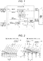
- FIG. 1 is a block diagram illustrating a configuration of a target detection device according to an embodiment.
- a target detection device 1 is configured by a first sensor 10, a second sensor 20, and a target analysis unit 30.
- the first sensor 10 is a millimeter-wave radar for a long distance with a small field of view.
- the second sensor 20 is a wide-angle sensor with a large field of view. As the wide-angle sensor 20, a medium-range radar, a stereo camera, a LiDAR, or the like is used.
- the target analysis unit 30 combines pieces of information (position, characteristic, detection accuracy) on targets detected by the first sensor 10 and the second sensor 20.
- the target analysis unit 30 corrects detection accuracies in consideration of a virtual image, and calculates a presence probability.
- Target information used to be combined and calculated by the target analysis unit 30 is transmitted to, for example, a driving control device 2 and used for autonomous driving control of the vehicle.
- the millimeter-wave radar 10 detects a target 1 when the reception level of a millimeter-wave signal reflected by an object, an SNR, or the like exceeds a set threshold value. At this time, a detection accuracy P1 indicating how accurately the target has been detected is output by how much a detection signal level exceeds the threshold value, in addition to the position U1 of the detected target 1. Furthermore, characteristic information such as the speed V1 of the target 1 and a reflection cross-section area (target size) S1 is also obtained and output by signal processing specific to the millimeter-wave radar 10.
- the wide-angle sensor 20 outputs the position U2 and a detection accuracy P2 of the target 2, which are detected by a target detection algorithm, are output together with the characteristic information such as the speed V2 and a reflection cross-section area (target size) S2.
- the target analysis unit 30 corrects the influence of the virtual image, and calculates and outputs a presence probability that the target is actually present.
- the virtual image transformation unit 101 performs transformation of a position by calculating a position F ⁇ U2 ⁇ at which a virtual image is expected to be generated in the case of the millimeter-wave radar 10 from the position U2 of the target 2, that is detected by the wide-angle sensor 20.
- the virtual image transformation unit 101 is passed as it is.
- the identical target determination unit 102 determines whether or not the target 1 detected by the millimeter-wave radar 10 is identical to the target 2 detected by the wide-angle sensor 20. That is, when the position F ⁇ U2 ⁇ of the virtual image of the target 2, that is transformed by the virtual image transformation unit 101 overlaps the position U1 of the target 1 of the millimeter-wave radar 10, and the characteristic information such as the speed V1 and the reflection cross-section area S1 coincides with the characteristic information such as the speed V2 and the reflection cross-section area S2, it is determined that the target 1 is identical to the target 2.
- the accuracy in such a determination can also be made accurate, and it is effective to reflect the accuracy in target information.
- the accuracy correction calculation unit 103 uses the detection accuracy P1 detected by the millimeter-wave radar 10 and the detection accuracy P2 detected by the wide-angle sensor 20 to perform a correction calculation of the detection accuracies of the target 1 and the target 2 in consideration of the virtual image.
- the calculation result is output as the probabilities (presence probabilities) Q1 and Q2 that the target 1 and the target 2 are actually present at this position.
- the combination processing unit 104 performs combination processing (weighting averaging) on the position U1 and the characteristic information (speed V1 and reflection cross-section area S1) of the target 1, and the position U2 and the characteristic information (speed V2 and reflection cross section S2) of the target 2.
- a false image inverse transformation unit 105 performs inverse transformation of the position of the target 2 to the original coordinates. Then, the target positions (U1' and U2) and the characteristic information (V1', V2', S1', and S2') combined by the combination processing unit 104 are output.
- the driving control device 2 receives, as an input, the presence probabilities Q1 and Q2 of the targets 1 and 2 and the position information and the characteristic information after the combination, and performs autonomous driving control of a vehicle. In this manner, it is possible to construct a portion of an autonomous driving system by combining the target detection device 1 and the driving control device 2.
- FIG. 2 is a diagram illustrating a virtual image generation mechanism in the millimeter-wave radar.
- the millimeter-wave radar 10 uses a reception array configured by a plurality of reception antennas 200 in order to detect the angular direction ⁇ of a target.
- a transmission signal of a specific frequency (wavelength ⁇ ) emitted from a transmission antenna (not illustrated) is reflected by a target and is received by the reception antenna 200.
- FIG. 2(a) illustrates a phase relation between reception signals in the respective reception antennas when a reception antenna interval d is small (d ⁇ ⁇ /2).
- FIG. 2 (b) illustrates a phase relation between reception signals in the reception antennas when the reception antenna interval d is large (d > ⁇ /2) .
- Reception signals X 1 to X 8 of the respective reception antennas 200 have a regular phase difference ⁇ 1 between adjacent antennas, in accordance with the angular direction ⁇ 1 of a target 201 to be detected.
- the angular direction ⁇ 1 of the target 201 can be obtained from the regular phase difference ⁇ 1 between the reception signals X 1 to X 8 .
- the regular phase difference ⁇ 1 does not exceed ⁇ 180 deg regardless of the angular direction ⁇ 1 of the target 201.
- a one-to-one relation is established between the phase difference ⁇ 1 and the angular direction ⁇ 1, and the virtual image of the target 201 is not generated.
- the antenna size is large in order to increase the antenna gain, and thus it is difficult to make the reception antenna distance d smaller than the half wavelength ⁇ /2 (about 2 mm).
- FIG. 2(b) illustrates the case where the antenna interval d is larger than the half wavelength ⁇ /2.
- the target detection is corrected by combining the wide-angle sensor 20 that does not cause the phase folding.
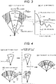
- FIG. 3 is a diagram illustrating comparison between detection characteristics between the millimeter-wave radar and the wide-angle sensor.
- FIG. 3(a) illustrates a field range of view and
- FIG. 3(b) illustrates angular-direction dependency of the gain.
- the position of a vehicle equipped with the millimeter-wave radar and the wide-angle sensor is set to 300. If a field range of view 301 (solid line, field ⁇ 1 of view) of the millimeter-wave radar 10 for a long distance is compared with a field range of view (broken line, field ⁇ 2 of view) 302 of the wide-angle sensor 20, when the detection distance is larger, the field of view is smaller ( ⁇ 1 ⁇ 2).
- the reason for obtaining such a field range of view is, as described with reference to FIG. 2 , that, when the radar is used for a long distance, the antenna size increases in order to increase the gain of the reception antenna, and the field of view is reduced as a result of increasing the antenna interval.
- a gain 303 of the millimeter-wave radar 10 has a large main lobe of the gain in a narrow angular range, but the gain decreases with a side lobe as the angular direction ⁇ increases.
- An occurrence boundary 304 of phase folding is set to an angular direction in which the phase difference between the adjacent antennas, which is determined by the antenna arrangement interval is 180 deg, and which is the same as a range of the main lobe of the gain 303 of the millimeter-wave radar.
- a gain 305 of the wide-angle sensor 20 gradually decreases as the angular direction ⁇ increases, and intersects with the gain 303 of the millimeter-wave radar. That is, in a range on the right side (range in which phase folding occurs) beyond the occurrence boundary 304 of phase folding in the millimeter-wave radar, the gain 305 of the wide-angle sensor is made larger than the gain 303 of the radar.
- FIG. 3(a) illustrates the position of a target detected as an example.
- a target 307 outside the main lobe is detected as a virtual image 306 in the field of view 301 of the millimeter-wave radar 10.
- the position of the target 307 is at a distant position in the field of view 302 of the wide-angle sensor 20, but the target 307 can also be detected by the wide-angle sensor 20 with the relation of the gain illustrated in FIG. 3(b) . It is a precondition of the present embodiment that such a gain relation is established.
- the wide-angle sensor 20 is a radar for a medium-range use for wide-angle applications, it is possible to realize a target detection device that is resistant to environmental changes without breaking the gain relation even in an environment such as darkness or rain. Furthermore, by sharing the transmission antenna and the transmission signal of the wide-angle sensor (medium-range radar) 20 with the radar 10 for a long distance, it is possible to construct a target detection device that has no environmental change such as changes in propagation characteristics and reflection state from a target and has higher robust property.
- the present embodiment is characterized by adding not only the position information of targets detected by the first and second sensors (millimeter-wave radar and wide-angle sensor) but also the information on the detection accuracy and using the information on the detection accuracy when pieces of data from the respective sensors are combined.
- the detection accuracy is an index that reflects the intensity of a detection signal when the targets are detected by the respective sensors.
- the detection accuracy is a numerical value obtained by using information such as an SNR, a size, and a distance of the detected target, and performing normalization between 0 and 100% in consideration of a difference in detection sensitivity between the sensors.
- FIG. 4 is a diagram illustrating an example of calculating the presence probability of a target when a virtual image is generated, in the accuracy correction calculation unit 103.
- FIG. 4 quantitatively illustrates that, when the millimeter-wave radar for a long distance detects a virtual image of a target, the target detected by the millimeter-wave radar is the virtual image, by using the detection accuracies of the millimeter-wave radar and the wide-angle sensor and calculating the presence probability.
- FIG. 4(a) illustrates the detection result by the millimeter-wave radar 10. It is assumed that a target 401 is detected in the field of view 301, and the detection accuracy P1 is 40%. However, it is assumed that the target 401 detected here is a virtual image of a target 402 detected by the wide-angle sensor 20 in FIG. 4(b) .
- FIG. 4(b) illustrates the detection result by the wide-angle sensor 20. It is assumed that the target 402 is detected outside the boundary 304, and the detection accuracy P2 is 70%. The target 402 is actual present, and corresponds to the target 401 (virtual image) detected by the millimeter-wave radar in FIG. 4(a) .
- FIG. 4(c) illustrates the correspondence of whether or not the two detected targets 401 and 402 are identical to each other.
- the position U2 of the target 402 detected by the wide-angle sensor is transformed into the position F ⁇ U2 ⁇ at which the target is predicted to be generated as a virtual image by the millimeter-wave radar, and the position after the transformation is indicated as the target 403.
- processing of moving to a position that is line-symmetrical with respect to the occurrence boundary 304 of phase folding, that is, a position folded by the line of the occurrence boundary 304 is performed.
- the position F ⁇ U2 ⁇ of the target 403 of the wide-angle sensor after the transformation is similar to the position U1 of the target 401 of the millimeter-wave radar, and the characteristic information such as the speed and the reflection cross-section area of the target 402 of the wide-angle sensor is similar to the characteristic information such as the speed and the reflection cross-section area of the target 401 of the millimeter-wave radar, it is determined that the target 402 of the wide-angle sensor is identical to the target 401 of the millimeter-wave radar. The determination is made by using not only the position information but also the characteristic information of the target such as the speed and the reflection cross-section area. The reason is as follows.
- the target that is actually present is erroneously determined to be a target by a virtual image.
- the target that is actually present is removed as the virtual image.
- the erroneous determination is reduced by setting a condition that the characteristic information is similar in addition to the position information.
- the target 401 detected by the millimeter-wave radar is identical to the target 402 detected by the wide-angle sensor, and it can be estimated that the target 401 of the millimeter-wave radar is a virtual image.
- whether or not the detected target is actually present at the detected position is quantitatively analyzed using the presence probability.
- FIG. 4(d) illustrates the calculation result of the presence probability of the detected target.
- the presence probabilities Q1 and Q2 indicating whether or not each target is actually present are calculated by combining the detection accuracy P1 of the target 401 and the detection accuracy P2 of the target 402, and correcting the detection accuracy in consideration of the virtual image.
- a calculation expression used here is as follows.
- the detection accuracy P1 of the target 401 by the millimeter-wave radar and the detection accuracy P2 of the target 402 by the wide-angle sensor are set, the presence probability Q1 of the target 401 considering the virtual image and the presence probability of the target 402 considering the virtual image Q2 is obtained by the following expressions.
- Q 1 P 1 ⁇ 1 ⁇ P 2
- Q 2 1 ⁇ 1 ⁇ P 2 ⁇ 1 ⁇ P 1 ⁇ P 2
- the presence probabilities obtained by the calculation are transmitted to the driving control device 2, and then are compared to a threshold value (for example, 20%) provided separately.
- a threshold value for example, 20%
- the accuracy correction calculation unit 103 calculates the presence probability of targets by using the detection accuracy of the target detected by the millimeter-wave radar and the detection accuracy of the target detected by the wide-angle sensor, and thus performs a correction so that the presence probability of the target having a possibility that the target is a virtual image is decreased, and the presence probability of the target (real image) being the source for generating a virtual image increases in accordance with the detection accuracy of the virtual image. This makes it possible to quantitatively determine whether or not the target is actually present, improve the reliability of the determination as compared with the related art, and prevent the erroneous detection of the target due to the generation of a virtual image.
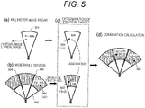
- FIG. 5 is a diagram illustrating an example of calculating the presence probability when the position of a virtual image overlaps another target.
- the presence probability indicates that the target detected by the millimeter-wave radar is a real image.
- FIG. 5(b) illustrates the detection result by the wide-angle sensor 20. It is assumed that the target (502) that is actually present is detected outside the boundary 304, and the detection accuracy P2 is 70%. A target corresponding to a real image portion of the target 501 in FIG. 5(a) is not detected inside the boundary 304. This is because, as described in FIG. 3 , the gain of the wide-angle sensor 20 is smaller than the gain of the millimeter-wave radar 10 inside the boundary 304.
- FIG. 5(c) illustrates the resultant obtained by transforming the position of the target 502 detected by the wide-angle sensor into the position at which the target is predicted to be generated as a virtual image by the millimeter-wave radar, and the position after the transformation is indicated as the target 503.
- the target 501 of the millimeter-wave radar and the target 503 of the wide-angle sensor after the transformation are determined to be identical to each other.
- FIG. 5(d) illustrates the calculation result of the presence probability of the detected target.
- the calculation in this case can be performed by using the expressions (1) and (2) as in the description made with reference to FIG. 4 , and the description in the middle will be omitted.
- the driving control device 2 it is determined that there is a high possibility that the target 501 is a target that is actually present, by comparing the probability with the threshold value (for example, 20%) provided separately, and the control is performed with the target 501 left.
- the driving control device 2 connected to the target detection device 1 determines the setting of the threshold value of the presence probability.
- the driving control device 2 sets an optimum threshold value in advance in accordance with applications such as driver assist applications and fully autonomous driving applications, and the driving conditions of the vehicle at that time.
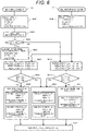
- FIG. 6 is a flowchart illustrating the entirety of analysis processing of a target by the target analysis unit 30.
- the analysis processing includes the calculation of the presence probability described with reference to FIGS. 4 and 5 .
- the processing contents of each step will be described.
- S601 Input information on the target 1 detected by the millimeter-wave radar 10.
- the information includes the three-dimensional position U1 (x1, y1, z1), the speed V1, the area S1, and the detection accuracy P1 of the target 1. Then, the information is transferred to S606 and S610.
- S602 Input information on the target 2 detected by the wide-angle sensor 20 at substantially the same timing as S601.
- the information includes the three-dimensional position U2 (x2, y2, z2), the speed V2, the area S2, and the detection accuracy P2 of the target 2.
- S604 Determine whether or not the angular direction ⁇ 2 of the target 2 obtained in S603 is a direction in which a virtual image is generated due to phase folding in the millimeter-wave radar 10. That is, it is determined whether or not to satisfy ⁇ 2> Th0 (occurrence boundary).
- the determination result is Yes (when the virtual image is generated)
- the process proceeds to S605.
- the determination result is No (when no virtual image is generated)
- the process proceeds to S610.
- the virtual image transformation unit 101 performs coordinate transformation for a position at which the virtual image is generated due to the folding of the target 2, and also performs transformation on the speed and the area in consideration of the folding. Data after the transformation to a virtual image is represented by the symbol F ⁇ _ ⁇ .
- the identical target determination unit 102 performs a calculating for determining whether or not the target 2 detected by the wide-angle sensor after virtual image transformation is identical to the target 1 detected by the millimeter-wave radar. In the calculation, a position error ⁇ U, a speed error ⁇ V, and an area error ⁇ S are calculated.
- S607 Determine whether or not all the position error ⁇ U, the speed error ⁇ V, and the area error ⁇ S which are calculated are smaller than threshold values Th1, Th2, and Th3 set in advance.
- the determination result is Yes, it is determined that the virtual image of the target 2 is identical to the target 1, Then, the process proceeds to S608.
- the determination result is No, it is determined that the target 1 is not identical to the target 2, and then the process proceeds to S609.
- S608 When it is determined in S607 that the targets are identical to each other, perform combination calculation of target information on the premise that the target 1 detected by the millimeter-wave radar is a virtual image. First, the accuracy correction calculation unit 103 calculates the presence probabilities Q1 and Q2 of the respective targets by using the detection accuracy P1 of the target 1 detected by the millimeter-wave radar and the detection accuracy P2 of the target 2 detected by the wide-angle sensor. In the calculation, the above expressions (1) and (2) are used.
- the combination processing unit 104 combines the target information (position U1, speed V1, and area S1) of the target 1 and the target information U2, V2, and S2 of the virtual image of the target 2 by weighting average or the like. Each piece of the target information after the combination is indicated by adding a dash symbol in FIG. 6 . Thus, it is possible to improve the detection accuracy of the target information.
- the pieces of target information of the target 1 and the target 2 subjected to the above processing are transferred to S613.
- S609 When it is determined in S607 that the targets are not identical to each other, the pieces of information on the target 1 and target 2 are transferred to S613 without performing particular processing. That is, the detection accuracies P1 and P2 themselves become the presence probabilities Q1 and Q2.
- the identical target determination unit 102 performs a calculation for determining whether or not the target 2 of the wide-angle sensor is identical to the target 1 of the millimeter-wave radar, without performing virtual image transformation. In the calculation, similar to S606, the position error ⁇ U, the speed error ⁇ V, and the area error ⁇ S are calculated.
- S611 Similar to S607, determine whether or not all the position error ⁇ U, the speed error ⁇ V, and the area error ⁇ S are smaller than threshold values Th1, Th2, and Th3. When the determination result is Yes, it is determined that the virtual image of the target 2 is identical to the target 1, Then, the process proceeds to S612. When the determination result is No, it is determined that the target 1 is not identical to the target 2. Then, the process proceeds to S609.
- the value is used as the presence probability of the target information after the correction. With this correction, the accuracy of the presence probability is improved.
- the combination processing unit 104 combines the pieces of target information (position, speed, and area) of the target 1 and the target 2. At this time, the reliability of the detection information is improved by performing weighting averaging or the like based on the detection accuracies P1 and P2 of the target 1 and the target 2.
- the target information (position U', speed V', and area S') after the combination is transferred to S613 together with the presence probability Q.
- the driving control device 2 determines how to control the vehicle in a state where the driving control device finally determines the presence state of a target based on the target information (position, speed, and area) and the presence probabilities Q (Q1 and Q2) that are transmitted from the target detection device 1, while comparing the transmitted target information with the target information previously detected.
- the control by the driving control device 2 is performed as follows, for example, by setting the threshold value of the presence probability Q of the target to 20%.
- the threshold value of the presence probability Q of the target is appropriately set in advance in accordance with the application.
- the target detection device in the present embodiment an erroneous detection of a virtual image due to phase folding to be a target that is actually present is prevented, and, even when the virtual image overlaps the position of another target that is actually present, overlooking the target that is actually present does not occur. This makes it possible to provide a target detection device having high reliability.
Landscapes
- Engineering & Computer Science (AREA)
- Radar, Positioning & Navigation (AREA)
- Remote Sensing (AREA)
- Physics & Mathematics (AREA)
- General Physics & Mathematics (AREA)
- Computer Networks & Wireless Communication (AREA)
- Electromagnetism (AREA)
- Radar Systems Or Details Thereof (AREA)
- Traffic Control Systems (AREA)
Abstract
Description
- The present invention relates to a target detection device that detects a target using a plurality of sensors.
- In an autonomous driving system of a vehicle, a millimeter-wave radar is used as one of sensors that detect targets such as obstacles and pedestrians with high accuracy. In the millimeter-wave radar, a plurality of reception antennas are arranged in an array, and the angular direction of the target is calculated based on amplitude/phase information of a reception signal of each antenna. The longer a distance from one end to the other end of the arranged antennas, that is, the longer an aperture length, the higher a resolution. Here, it is known that, if the antennas are arranged at intervals longer than the half of the wavelength (λ/2) of the reception signal, and the angular direction exceeds the boundary value, a virtual image is generated due to phase folding. When the virtual image is generated, there is a concern that the angular direction in which the target is actually present is erroneously calculated. Thus, the virtual image is removed to prevent an erroneous detection.
- In this regard, in a radar device disclosed in
PTL 1, an object is to reliably obtain an angle at which a target is actually present. The radar device includes transmission means for respectively outputting first, second, and third transmission waves from first, second, and third transmission antennas having transmission directions that are sequentially different from each other in a horizontal direction, first phase folding determination means for determining whether or not an angle of a target is an angle with phase folding, based on a first reception level of a reception signal by the first transmission antenna and a third reception level of a reception signal by the third transmission antenna, and second phase folding determination means for determining whether or not the angle of the target is the angle with phase folding, based on the determination result and a second reception level of a reception signal by the second transmission antenna. - A direction detection device disclosed in
PTL 2 includes a configuration in which a position at which a target is required to be detected on an image pickup screen picked up by a CCD camera is calculated based on a distance, a relative speed, and a direction of the target, which are detected using a radar wave, and then it is determined whether or not the target is present at the calculated position. Then, a configuration as follows is made. If the target is not present, the direction is calculated again assuming that a phase difference Δθ of the reception signal used to calculate the direction of the target has phase folding. A prediction position at which a target object is required to be detected on the image pickup screen is calculated using the calculated direction. Then, if the target is present at the prediction position, a direction correction in which the direction used to calculate the prediction position is used as the direction of the target is performed. -
- PTL 1:
JP 2015-68724 A - PTL 2:
JP 2007-263986 A - When a virtual image is generated due to phase folding in a millimeter-wave radar, according to the configuration in
PTL 1, the target (virtual image) detected by determining that the angle of the target is an angle with phase folding can be removed. However, an actual target may be present at the position of the virtual image generated due to phase folding, in an overlapping manner. In such a case, in the technique disclosed inPTL 1, if the threshold value for determining phase folding is not appropriate, there is a concern that the actual target is regarded as a virtual image by the determination and is erroneously removed. The reason is as follows. When a virtual image at a deep angle position and the actual target at a shallow angle position overlap each other due to phase folding, if the transmission antenna is switched, the level of a reception signal changes by an influence of the virtual image. Thus, there is a high possibility that the actual target is overlooked and is determined to be a virtual image. - The above description is similarly applied to the configuration in
PTL 2. If another target is present at the original position assuming phase folding, there is a concern that the actual target is erroneously determined to be a virtual image due to phase folding and, then removed. In this case as well, there is a concern that the actual target is set to be not detected. - An object of the present invention is to provide a target detection device that detects a target by suppressing a virtual image without overlooking an actual target even when the virtual image generated by phase folding and the actual target overlap each other.
- According to the present invention, a target detection device includes a first sensor that detects a target in a first field of view, a second sensor that detects a target in a second field of view, that is larger than the first field of view, and a target analysis unit that receives, as an input, detection information on a first target detected by the first sensor and detection information on a second target detected by the second sensor, and outputs a presence probability indicating a position at which the target is actually present. The detection information includes a position and characteristic information of the target, and a detection accuracy indicating how accurately the target has been detected. The target analysis unit includes an identical target determination unit that determines whether or not the first target is identical to the second target by comparing a position and characteristic information of the first target with a position and characteristic information of the second target, and an accuracy correction calculation unit that corrects a detection accuracy of the first target by using a detection accuracy of the second target and calculates a presence probability that the first target is actually present, when, as a result of the determination of the identical target determination unit, the first target is estimated to be a virtual image of the second target.
- According to the present invention, it is possible to obtain an effect of preventing an erroneous detection of a target due to a virtual image and preventing an undetection of a target that is actually present, and the reliability of a target detection device is improved.
-
- [
FIG. 1] FIG. 1 is a block diagram illustrating a configuration of a target detection device according to an embodiment. - [
FIG. 2] FIG. 2 is a diagram illustrating a virtual image generation mechanism in a millimeter-wave radar. - [
FIG. 3] FIG. 3 is a diagram illustrating a comparison of detection characteristics between the millimeter-wave radar and a wide-angle sensor. - [
FIG. 4] FIG. 4 is a diagram illustrating an example of calculating a presence probability of a target when a virtual image is generated. - [
FIG. 5] FIG. 5 is a diagram illustrating an example of calculating the presence probability when a position of the virtual image overlaps another target. - [
FIG. 6] FIG. 6 is a flowchart illustrating an entirety of analysis processing of a target. - An embodiment of the present invention will be described with reference to the drawings.
-
FIG. 1 is a block diagram illustrating a configuration of a target detection device according to an embodiment. Atarget detection device 1 is configured by afirst sensor 10, asecond sensor 20, and atarget analysis unit 30. Thefirst sensor 10 is a millimeter-wave radar for a long distance with a small field of view. Thesecond sensor 20 is a wide-angle sensor with a large field of view. As the wide-angle sensor 20, a medium-range radar, a stereo camera, a LiDAR, or the like is used. Thetarget analysis unit 30 combines pieces of information (position, characteristic, detection accuracy) on targets detected by thefirst sensor 10 and thesecond sensor 20. The target analysis unit 30 corrects detection accuracies in consideration of a virtual image, and calculates a presence probability. Target information used to be combined and calculated by thetarget analysis unit 30 is transmitted to, for example, adriving control device 2 and used for autonomous driving control of the vehicle. - The millimeter-
wave radar 10 detects atarget 1 when the reception level of a millimeter-wave signal reflected by an object, an SNR, or the like exceeds a set threshold value. At this time, a detection accuracy P1 indicating how accurately the target has been detected is output by how much a detection signal level exceeds the threshold value, in addition to the position U1 of the detectedtarget 1. Furthermore, characteristic information such as the speed V1 of thetarget 1 and a reflection cross-section area (target size) S1 is also obtained and output by signal processing specific to the millimeter-wave radar 10. - Similarly, the wide-
angle sensor 20 outputs the position U2 and a detection accuracy P2 of thetarget 2, which are detected by a target detection algorithm, are output together with the characteristic information such as the speed V2 and a reflection cross-section area (target size) S2. - The operation of the
target analysis unit 30 will be described. In the millimeter-wave radar 10 for a long distance with a small field of view, when a target is present outside the field of view, a virtual image of the target is generated inside the field of view and is detected. On the other hand, in the wide-angle sensor 20 having a large field of view, no virtual image is generated for the target within the field of view. That is, it is possible to also detect a target that is present at an angle that is greatly inclined from a front direction, as a real image. Further, it is possible to calculate the position at which the virtual image is generated in the field of view, from the position of the target that is actually present outside the field of view. Thus, thetarget analysis unit 30 corrects the influence of the virtual image, and calculates and outputs a presence probability that the target is actually present. - The virtual
image transformation unit 101 performs transformation of a position by calculating a position F{U2} at which a virtual image is expected to be generated in the case of the millimeter-wave radar 10 from the position U2 of thetarget 2, that is detected by the wide-angle sensor 20. When the position U2 of thetarget 2 is at an angle close to the front direction in which a virtual image is not generated by the millimeter-wave radar 10, the virtualimage transformation unit 101 is passed as it is. - The identical
target determination unit 102 determines whether or not thetarget 1 detected by the millimeter-wave radar 10 is identical to thetarget 2 detected by the wide-angle sensor 20. That is, when the position F{U2} of the virtual image of thetarget 2, that is transformed by the virtualimage transformation unit 101 overlaps the position U1 of thetarget 1 of the millimeter-wave radar 10, and the characteristic information such as the speed V1 and the reflection cross-section area S1 coincides with the characteristic information such as the speed V2 and the reflection cross-section area S2, it is determined that thetarget 1 is identical to thetarget 2. The accuracy in such a determination can also be made accurate, and it is effective to reflect the accuracy in target information. - When it is determined that the
target 1 is identical to thetarget 2, thetarget 1 detected by the millimeter-wave radar 10 is estimated to be a virtual image of thetarget 2. Therefore, the accuracycorrection calculation unit 103 uses the detection accuracy P1 detected by the millimeter-wave radar 10 and the detection accuracy P2 detected by the wide-angle sensor 20 to perform a correction calculation of the detection accuracies of thetarget 1 and thetarget 2 in consideration of the virtual image. The calculation result is output as the probabilities (presence probabilities) Q1 and Q2 that thetarget 1 and thetarget 2 are actually present at this position. - The
combination processing unit 104 performs combination processing (weighting averaging) on the position U1 and the characteristic information (speed V1 and reflection cross-section area S1) of thetarget 1, and the position U2 and the characteristic information (speed V2 and reflection cross section S2) of thetarget 2. - When the virtual
image transformation unit 101 performs coordinate transformation of the position of thetarget 2, a false imageinverse transformation unit 105 performs inverse transformation of the position of thetarget 2 to the original coordinates. Then, the target positions (U1' and U2) and the characteristic information (V1', V2', S1', and S2') combined by thecombination processing unit 104 are output. - The driving
control device 2 receives, as an input, the presence probabilities Q1 and Q2 of thetargets target detection device 1 and the drivingcontrol device 2. -
FIG. 2 is a diagram illustrating a virtual image generation mechanism in the millimeter-wave radar. The millimeter-wave radar 10 uses a reception array configured by a plurality ofreception antennas 200 in order to detect the angular direction θ of a target. A transmission signal of a specific frequency (wavelength λ) emitted from a transmission antenna (not illustrated) is reflected by a target and is received by thereception antenna 200.FIG. 2(a) illustrates a phase relation between reception signals in the respective reception antennas when a reception antenna interval d is small (d < λ/2).FIG. 2 (b) illustrates a phase relation between reception signals in the reception antennas when the reception antenna interval d is large (d > λ/2) . - The case of (a) will be described. Reception signals X1 to X8 of the
respective reception antennas 200 have a regular phase difference ϕ1 between adjacent antennas, in accordance with the angular direction θ1 of atarget 201 to be detected. Conversely, the angular direction θ1 of thetarget 201 can be obtained from the regular phase difference ϕ1 between the reception signals X1 to X8. When the reception antenna interval d is shorter than the half wavelength λ/2, the regular phase difference ϕ1 does not exceed ±180 deg regardless of the angular direction θ1 of thetarget 201. Thus, a one-to-one relation is established between the phase difference ϕ1 and the angular direction θ1, and the virtual image of thetarget 201 is not generated. - However, in the radar for long distance applications, that uses a high frequency such as millimeter waves (for example, 76 GHz, wavelength λ = about 4 mm), the antenna size is large in order to increase the antenna gain, and thus it is difficult to make the reception antenna distance d smaller than the half wavelength λ/2 (about 2 mm).
-
FIG. 2(b) illustrates the case where the antenna interval d is larger than the half wavelength λ/2. When atarget 202 is in a deep angular direction θ2, a regular phase difference ϕ2 between the reception signals exceeds ±180 deg. Thus, it is not possible to distinguish the regular phase difference ϕ2 from a phase difference ϕ3 in a case of a shallow angular direction θ3. That is, a relation of ϕ2 = ϕ3 ± 180deg is obtained. Therefore, thetarget 202 in the deep angular direction θ2 is erroneously detected as atarget 203 in the shallow angular direction θ3. This phenomenon is called phase folding, and thetarget 203 in the shallow angular direction θ3 is detected as a virtual image of thetarget 202 at the deep angular direction θ2. - In the present embodiment, in the case of the millimeter-
wave radar 10 for long distance applications, in order to suppress a virtual image generated due to phase folding, the target detection is corrected by combining the wide-angle sensor 20 that does not cause the phase folding. -
FIG. 3 is a diagram illustrating comparison between detection characteristics between the millimeter-wave radar and the wide-angle sensor.FIG. 3(a) illustrates a field range of view andFIG. 3(b) illustrates angular-direction dependency of the gain. By combining the detection characteristics of the millimeter-wave radar and the wide-angle sensor in this relation, it is possible to suppress a virtual image generated due to phase folding. - In
FIG. 3(a) , the position of a vehicle equipped with the millimeter-wave radar and the wide-angle sensor is set to 300. If a field range of view 301 (solid line, field α1 of view) of the millimeter-wave radar 10 for a long distance is compared with a field range of view (broken line, field α2 of view) 302 of the wide-angle sensor 20, when the detection distance is larger, the field of view is smaller (α1 <α2). The reason for obtaining such a field range of view is, as described with reference toFIG. 2 , that, when the radar is used for a long distance, the antenna size increases in order to increase the gain of the reception antenna, and the field of view is reduced as a result of increasing the antenna interval. - In
FIG. 3(b) , again 303 of the millimeter-wave radar 10 has a large main lobe of the gain in a narrow angular range, but the gain decreases with a side lobe as the angular direction θ increases. Anoccurrence boundary 304 of phase folding is set to an angular direction in which the phase difference between the adjacent antennas, which is determined by the antenna arrangement interval is 180 deg, and which is the same as a range of the main lobe of thegain 303 of the millimeter-wave radar. - On the other hand, a
gain 305 of the wide-angle sensor 20 gradually decreases as the angular direction θ increases, and intersects with thegain 303 of the millimeter-wave radar. That is, in a range on the right side (range in which phase folding occurs) beyond theoccurrence boundary 304 of phase folding in the millimeter-wave radar, thegain 305 of the wide-angle sensor is made larger than thegain 303 of the radar. Thus, when a virtual image can be seen due to phase folding in a millimeter-wave radar, a real image as the source of the virtual image can also be seen in a wide-angle sensor. -
FIG. 3(a) illustrates the position of a target detected as an example. When reflection by the target to be detected is strong, atarget 307 outside the main lobe is detected as avirtual image 306 in the field ofview 301 of the millimeter-wave radar 10. At this time, the position of thetarget 307 is at a distant position in the field ofview 302 of the wide-angle sensor 20, but thetarget 307 can also be detected by the wide-angle sensor 20 with the relation of the gain illustrated inFIG. 3(b) . It is a precondition of the present embodiment that such a gain relation is established. - Here, as long as the wide-
angle sensor 20 is a radar for a medium-range use for wide-angle applications, it is possible to realize a target detection device that is resistant to environmental changes without breaking the gain relation even in an environment such as darkness or rain. Furthermore, by sharing the transmission antenna and the transmission signal of the wide-angle sensor (medium-range radar) 20 with theradar 10 for a long distance, it is possible to construct a target detection device that has no environmental change such as changes in propagation characteristics and reflection state from a target and has higher robust property. - The present embodiment is characterized by adding not only the position information of targets detected by the first and second sensors (millimeter-wave radar and wide-angle sensor) but also the information on the detection accuracy and using the information on the detection accuracy when pieces of data from the respective sensors are combined. Here, the detection accuracy is an index that reflects the intensity of a detection signal when the targets are detected by the respective sensors. Specifically, the detection accuracy is a numerical value obtained by using information such as an SNR, a size, and a distance of the detected target, and performing normalization between 0 and 100% in consideration of a difference in detection sensitivity between the sensors. By using the value of the detection accuracy obtained in this manner, it is possible to calculate the probability (presence probability) that the target is actually present at the position in consideration of the generation of the virtual image.
-
FIG. 4 is a diagram illustrating an example of calculating the presence probability of a target when a virtual image is generated, in the accuracycorrection calculation unit 103.FIG. 4 quantitatively illustrates that, when the millimeter-wave radar for a long distance detects a virtual image of a target, the target detected by the millimeter-wave radar is the virtual image, by using the detection accuracies of the millimeter-wave radar and the wide-angle sensor and calculating the presence probability. -
FIG. 4(a) illustrates the detection result by the millimeter-wave radar 10. It is assumed that atarget 401 is detected in the field ofview 301, and the detection accuracy P1 is 40%. However, it is assumed that thetarget 401 detected here is a virtual image of atarget 402 detected by the wide-angle sensor 20 inFIG. 4(b) . -
FIG. 4(b) illustrates the detection result by the wide-angle sensor 20. It is assumed that thetarget 402 is detected outside theboundary 304, and the detection accuracy P2 is 70%. Thetarget 402 is actual present, and corresponds to the target 401 (virtual image) detected by the millimeter-wave radar inFIG. 4(a) . - Here, the reason that the detection accuracy P2 (= 70%) of the wide-angle sensor is higher than the detection accuracy P1 (= 40%) of the millimeter-wave radar is that the
gain 305 of the wide-angle sensor is greater than thegain 303 of the millimeter-wave radar in a range in which phase folding occurs (outside the boundary 304) as inFIG. 3 . -
FIG. 4(c) illustrates the correspondence of whether or not the two detectedtargets target 402 detected by the wide-angle sensor is transformed into the position F{U2} at which the target is predicted to be generated as a virtual image by the millimeter-wave radar, and the position after the transformation is indicated as thetarget 403. In the transformation of the position, processing of moving to a position that is line-symmetrical with respect to theoccurrence boundary 304 of phase folding, that is, a position folded by the line of theoccurrence boundary 304 is performed. - When the position F{U2} of the
target 403 of the wide-angle sensor after the transformation is similar to the position U1 of thetarget 401 of the millimeter-wave radar, and the characteristic information such as the speed and the reflection cross-section area of thetarget 402 of the wide-angle sensor is similar to the characteristic information such as the speed and the reflection cross-section area of thetarget 401 of the millimeter-wave radar, it is determined that thetarget 402 of the wide-angle sensor is identical to thetarget 401 of the millimeter-wave radar. The determination is made by using not only the position information but also the characteristic information of the target such as the speed and the reflection cross-section area. The reason is as follows. - For example, there may be other targets near the position at which the virtual image is generated. In a method of determining whether or not the targets are identical to each other only by the positions of the targets corresponding to each other, there is a concern that the target that is actually present is erroneously determined to be a target by a virtual image. As a result of the erroneous determination, the target that is actually present is removed as the virtual image. For example, in the case of autonomous driving, the risk of collision with an obstacle that is actually present increases. In particular, in a situation where many targets are detected, the erroneous determination may occur frequently. Thus, the erroneous determination is reduced by setting a condition that the characteristic information is similar in addition to the position information. Although both the speed and the reflection cross-section area (target size) are taken up as characteristic information here, either one is also effective, and other type of characteristic information may be added.
- From the above description, it can be determined that the
target 401 detected by the millimeter-wave radar is identical to thetarget 402 detected by the wide-angle sensor, and it can be estimated that thetarget 401 of the millimeter-wave radar is a virtual image. In the present embodiment, further, whether or not the detected target is actually present at the detected position is quantitatively analyzed using the presence probability. -
FIG. 4(d) illustrates the calculation result of the presence probability of the detected target. In the calculation, the presence probabilities Q1 and Q2 indicating whether or not each target is actually present are calculated by combining the detection accuracy P1 of thetarget 401 and the detection accuracy P2 of thetarget 402, and correcting the detection accuracy in consideration of the virtual image. - For the
target 401 of the millimeter-wave radar, the detection accuracy P1 is 40%, but the probability that the target is a virtual image is considered to be 70% which is the detection accuracy P2 of thetarget 402 of the wide-angle sensor. That is, the probability that thetarget 401 is a virtual image is 40% × 70% = 28%. Conversely, the probability that thetarget 401 is not a virtual image (that is, the probability that thetarget 401 is a real image) is considered to be the remaining portion that is 100-70 = 30% of thedetection accuracy 70% of thetarget 402, and the presence probability Q1 that thetarget 401 is actually present is 40% x 30% = 12%.FIG. 4(d) illustrates the presence probability Q1 (= 12%) of thetarget 404 after correction, which correspond to the detection accuracy P1 of thetarget 401. - On the other hand, the probability that the
target 402 of the wide-angle sensor is not present is 30% because the detection accuracy P2 is 70%. Further, as described above, since the probability that thetarget 401 is present as a virtual image is 28%, the probability that thetarget 401 is not present as the virtual image is 72%. From the above description, the probability that thetarget 402 is not present is 30% × 72% = about 22%, and the presence probability Q2 is about 78%.FIG. 4(d) illustrates the presence probability Q2 (= 78%) of thetarget 405 after the correction, which corresponds to the detection accuracy P2 of thetarget 402. - A calculation expression used here is as follows. When the detection accuracy P1 of the
target 401 by the millimeter-wave radar and the detection accuracy P2 of thetarget 402 by the wide-angle sensor are set, the presence probability Q1 of thetarget 401 considering the virtual image and the presence probability of thetarget 402 considering the virtual image Q2 is obtained by the following expressions.

- According to the calculation result in
FIG. 4(d) , the probability that the target 401 (404) detected by the millimeter-wave radar is a real image is low (Q1 = 12%), and the probability that the target 402 (405) detected by the wide-angle sensor is a real image is high (Q2 = 78%). The presence probabilities obtained by the calculation are transmitted to the drivingcontrol device 2, and then are compared to a threshold value (for example, 20%) provided separately. Thus, it is determined that there is a high possibility that thetarget 401 detected by the millimeter-wave radar is a virtual image, and control is performed with thetarget 401 removed. - As described above, the accuracy
correction calculation unit 103 calculates the presence probability of targets by using the detection accuracy of the target detected by the millimeter-wave radar and the detection accuracy of the target detected by the wide-angle sensor, and thus performs a correction so that the presence probability of the target having a possibility that the target is a virtual image is decreased, and the presence probability of the target (real image) being the source for generating a virtual image increases in accordance with the detection accuracy of the virtual image. This makes it possible to quantitatively determine whether or not the target is actually present, improve the reliability of the determination as compared with the related art, and prevent the erroneous detection of the target due to the generation of a virtual image. -
FIG. 5 is a diagram illustrating an example of calculating the presence probability when the position of a virtual image overlaps another target. Here, when another target is actually present at the position where a virtual image is generated, the presence probability indicates that the target detected by the millimeter-wave radar is a real image. -
FIG. 5(a) illustrates the detection result by the millimeter-wave radar 10. It is assumed that atarget 501 is detected, and the detection accuracy P1 is 90%. However, it is assumed that thetarget 501 detected here indicates that the virtual image of atarget 502 detected by the wide-angle sensor 20 inFIG. 5(b) overlaps another target (real image) at the same position. In addition, the reason that the detection accuracy P1 (= 90%) of thetarget 501 is higher than the detection accuracy P1 (= 40%) of thetarget 401 inFIG. 4(a) is that a signal level increases by the overlap between the virtual image and the other target (real image). -
FIG. 5(b) illustrates the detection result by the wide-angle sensor 20. It is assumed that the target (502) that is actually present is detected outside theboundary 304, and the detection accuracy P2 is 70%. A target corresponding to a real image portion of thetarget 501 inFIG. 5(a) is not detected inside theboundary 304. This is because, as described inFIG. 3 , the gain of the wide-angle sensor 20 is smaller than the gain of the millimeter-wave radar 10 inside theboundary 304. -
FIG. 5(c) illustrates the resultant obtained by transforming the position of thetarget 502 detected by the wide-angle sensor into the position at which the target is predicted to be generated as a virtual image by the millimeter-wave radar, and the position after the transformation is indicated as thetarget 503. Here, similar to the description made with reference toFIG. 4 , it is assumed that thetarget 501 of the millimeter-wave radar and thetarget 503 of the wide-angle sensor after the transformation are determined to be identical to each other. -
FIG. 5(d) illustrates the calculation result of the presence probability of the detected target. The calculation in this case can be performed by using the expressions (1) and (2) as in the description made with reference toFIG. 4 , and the description in the middle will be omitted. - The presence probability of the
target 504 after correction considering the virtual image, which corresponds to thetarget 501 detected by the millimeter-wave radar is Q1 = 27%. On the other hand, the presence probability of thetarget 505 after correction considering the virtual image, which corresponds to thetarget 502 detected by the wide-angle sensor is Q2 = 92%. According to such calculation results, the probability Q1 = 27% that the target 501 (504) detected by the millimeter-wave radar is a real image is higher than the probability Q1 = 12% of the target 401 (404) inFIG. 4 . In the drivingcontrol device 2, it is determined that there is a high possibility that thetarget 501 is a target that is actually present, by comparing the probability with the threshold value (for example, 20%) provided separately, and the control is performed with thetarget 501 left. - That is, it is possible to prevent an occurrence of a situation in which a target that is actually present is not detected, by leaving the target having a presence probability that is equal to or greater than a predetermined value when the virtual image and the target that is actually present overlap each other. As a result, it is possible to avoid the risk of collision with an obstacle by completely removing the target as in the related art.
- The driving
control device 2 connected to thetarget detection device 1 determines the setting of the threshold value of the presence probability. The drivingcontrol device 2 sets an optimum threshold value in advance in accordance with applications such as driver assist applications and fully autonomous driving applications, and the driving conditions of the vehicle at that time. -
FIG. 6 is a flowchart illustrating the entirety of analysis processing of a target by thetarget analysis unit 30. The analysis processing includes the calculation of the presence probability described with reference toFIGS. 4 and5 . The processing contents of each step will be described. - S601: Input information on the
target 1 detected by the millimeter-wave radar 10. The information includes the three-dimensional position U1 (x1, y1, z1), the speed V1, the area S1, and the detection accuracy P1 of thetarget 1. Then, the information is transferred to S606 and S610. - S602: Input information on the
target 2 detected by the wide-angle sensor 20 at substantially the same timing as S601. The information includes the three-dimensional position U2 (x2, y2, z2), the speed V2, the area S2, and the detection accuracy P2 of thetarget 2. - S603: Obtain the angular direction θ of the
target 2 output from the wide-angle sensor 20 from the position information (x2, y2) (calculation expression θ2 = atan(y2/x2)) . - S604: Determine whether or not the angular direction θ2 of the
target 2 obtained in S603 is a direction in which a virtual image is generated due to phase folding in the millimeter-wave radar 10. That is, it is determined whether or not to satisfy θ2> Th0 (occurrence boundary). When the determination result is Yes (when the virtual image is generated), the process proceeds to S605. When the determination result is No (when no virtual image is generated), the process proceeds to S610. - S605: The virtual
image transformation unit 101 performs coordinate transformation for a position at which the virtual image is generated due to the folding of thetarget 2, and also performs transformation on the speed and the area in consideration of the folding. Data after the transformation to a virtual image is represented by the symbol F{_}. - S606: The identical
target determination unit 102 performs a calculating for determining whether or not thetarget 2 detected by the wide-angle sensor after virtual image transformation is identical to thetarget 1 detected by the millimeter-wave radar. In the calculation, a position error ΔU, a speed error ΔV, and an area error ΔS are calculated. - S607: Determine whether or not all the position error ΔU, the speed error ΔV, and the area error ΔS which are calculated are smaller than threshold values Th1, Th2, and Th3 set in advance. When the determination result is Yes, it is determined that the virtual image of the
target 2 is identical to thetarget 1, Then, the process proceeds to S608. When the determination result is No, it is determined that thetarget 1 is not identical to thetarget 2, and then the process proceeds to S609. In this determination, it is also possible to quantify how accurately the targets can be determined to be identical to each other, depending on how much margin (difference from the threshold value) is provided for the threshold values Th1, Th2, and Th3 set in advance. - S608: When it is determined in S607 that the targets are identical to each other, perform combination calculation of target information on the premise that the
target 1 detected by the millimeter-wave radar is a virtual image. First, the accuracycorrection calculation unit 103 calculates the presence probabilities Q1 and Q2 of the respective targets by using the detection accuracy P1 of thetarget 1 detected by the millimeter-wave radar and the detection accuracy P2 of thetarget 2 detected by the wide-angle sensor. In the calculation, the above expressions (1) and (2) are used. - The
combination processing unit 104 combines the target information (position U1, speed V1, and area S1) of thetarget 1 and the target information U2, V2, and S2 of the virtual image of thetarget 2 by weighting average or the like. Each piece of the target information after the combination is indicated by adding a dash symbol inFIG. 6 . Thus, it is possible to improve the detection accuracy of the target information. The pieces of target information of thetarget 1 and thetarget 2 subjected to the above processing are transferred to S613. - S609: When it is determined in S607 that the targets are not identical to each other, the pieces of information on the
target 1 andtarget 2 are transferred to S613 without performing particular processing. That is, the detection accuracies P1 and P2 themselves become the presence probabilities Q1 and Q2. - S610: When the determination in S604 is No (when no virtual image is generated), the identical
target determination unit 102 performs a calculation for determining whether or not thetarget 2 of the wide-angle sensor is identical to thetarget 1 of the millimeter-wave radar, without performing virtual image transformation. In the calculation, similar to S606, the position error ΔU, the speed error ΔV, and the area error ΔS are calculated. - S611: Similar to S607, determine whether or not all the position error ΔU, the speed error ΔV, and the area error ΔS are smaller than threshold values Th1, Th2, and Th3. When the determination result is Yes, it is determined that the virtual image of the
target 2 is identical to thetarget 1, Then, the process proceeds to S612. When the determination result is No, it is determined that thetarget 1 is not identical to thetarget 2. Then, the process proceeds to S609. - S612: When it is determined in S611 that the targets are identical to each other, perform combination calculation of the target information. First, the accuracy
correction calculation unit 103 corrects the detection accuracy of the target information to obtain the presence probability. From the probability (1-P1) that thetarget 1 of the millimeter-wave radar is not present and the probability (1-P2) that thetarget 2 of the wide-angle sensor is not present, the probability that both the sensors erroneously detect the presence is (1-P1) × (1-P2). From this, the presence probability Q is as follows:
- In addition, the value is used as the presence probability of the target information after the correction. With this correction, the accuracy of the presence probability is improved.
- In addition, the
combination processing unit 104 combines the pieces of target information (position, speed, and area) of thetarget 1 and thetarget 2. At this time, the reliability of the detection information is improved by performing weighting averaging or the like based on the detection accuracies P1 and P2 of thetarget 1 and thetarget 2. The target information (position U', speed V', and area S') after the combination is transferred to S613 together with the presence probability Q. - S613: The driving
control device 2 determines how to control the vehicle in a state where the driving control device finally determines the presence state of a target based on the target information (position, speed, and area) and the presence probabilities Q (Q1 and Q2) that are transmitted from thetarget detection device 1, while comparing the transmitted target information with the target information previously detected. - The control by the driving
control device 2 is performed as follows, for example, by setting the threshold value of the presence probability Q of the target to 20%. When a target is detected at a position far away in a traveling direction with a presence probability Q = 30%, tracking of the target is started while starting deceleration. Alternatively, if a target is detected at a short distance but the presence probability Q is as low as 10%, and it is not possible to be associated with the previous tracking target, only the tracking is started on the premise that the target is not actually present. Then, when the probability Q rises to 90% in the next frame after the tracking starts, it is determined to be in a situation in which the brake is applied, and the vehicle is controlled. Since the threshold value of the presence probability for performing such determination and control differs depending on the applications such as the driver assist applications and the fully autonomous driving applications, the threshold value is appropriately set in advance in accordance with the application. - As described above, according to the target detection device in the present embodiment, an erroneous detection of a virtual image due to phase folding to be a target that is actually present is prevented, and, even when the virtual image overlaps the position of another target that is actually present, overlooking the target that is actually present does not occur. This makes it possible to provide a target detection device having high reliability.
-
- 1
- target detection device
- 2
- driving control device
- 10
- millimeter-wave radar (first sensor)
- 20
- wide-angle sensor (second sensor)
- 30
- target analysis unit
- 101
- virtual image transformation unit
- 102
- identical target determination unit
- 103
- accuracy correction calculation unit
- 104
- combination processing unit
- 105
- false image inverse transformation unit
- 200
- reception antenna
- 301
- field range of view of millimeter-wave radar
- 302
- field range of view of wide-angle sensor
- 303
- gain of millimeter-wave radar
- 304
- occurrence boundary of phase folding
- 305
- gain of wide-angle sensor
- 401 to 405, 501 to 505
- target
- P1, P2
- detection accuracy
- Q1, Q2
- presence probability
Claims (10)
- A target detection device comprising:a first sensor that detects a target in a first field of view;a second sensor that detects a target in a second field of view that is larger than the first field of view; anda target analysis unit that receives, as an input, detection information on a first target detected by the first sensor and detection information on a second target detected by the second sensor, and outputs a presence probability indicating a position at which the target is actually present,wherein the detection information includes a position and characteristic information of the target, and a detection accuracy indicating how accurately the target has been detected,the target analysis unit includesan identical target determination unit that determines whether or not the first target is identical to the second target by comparing a position and characteristic information of the first target with a position and characteristic information of the second target, andan accuracy correction calculation unit that corrects a detection accuracy of the first target by using a detection accuracy of the second target and calculates a presence probability that the first target is actually present, when, as a result of the determination of the identical target determination unit, the first target is estimated to be a virtual image of the second target.
- The target detection device according to claim 1, whereinthe target analysis unit further includes a virtual image transformation unit that transforms the position of the second target into a position at which the virtual image is generated within the first field of view, when the second target is detected outside the first field of view, andthe identical target determination unit compares the position of the first target with the position of the second target obtained by transformation of the virtual image transformation unit.
- The target detection device according to claim 2, wherein a gain of the second sensor is greater than a gain of the first sensor in a range outside the first field of view.
- The target detection device according to claim 3, wherein the first sensor is a long-range radar, and the second sensor is a medium-range radar.
- The target detection device according to claim 4, wherein the long-range radar and the medium-range radar transmit a common transmission signal from a common transmission antenna.
- The target detection device according to claim 1, wherein the characteristic information includes at least one of a speed and an area of the target.
- The target detection device according to claim 1, wherein, when, as the result of the determination of the identical target determination unit, the first target is estimated not to be the virtual image of the second target, the accuracy correction calculation unit outputs the detection accuracy of the first target and the detection accuracy of the second target as the presence probability that the first target is actually present, and a presence probability that the second target is actually present, respectively.
- The target detection device according to claim 1, wherein, when the first target is estimated to be the virtual image of the second target, and the detection accuracies of the first target and the second target are respectively P1 and P2, the accuracy correction calculation unit calculates the presence probabilities Q1 and Q2 of the first target and the second target by the following expressions.


- A target detection method comprising:a step of detecting a target by a first sensor having a first field of view;a step of detecting a target by a second sensor having a second field of view, that is larger than the first field of view; anda target analysis step of outputting a presence probability indicating a position at which the target is actually present, from detection information on a first target detected by the first sensor and detection information on a second target detected by the second sensor,wherein the detection information includes a position and characteristic information of the target, and a detection accuracy indicating how accurately the target has been detected,the target analysis step includesa determination step of determining whether or not the first target is identical to the second target by comparing a position and characteristic information of the first target with a position and characteristic information of the second target, anda calculation step of correcting a detection accuracy of the first target by using a detection accuracy of the second target and calculating a presence probability that the first target is actually present, when, as a result of the determination, the first target is estimated to be a virtual image of the second target.
- The target detection method according to claim 9, whereinthe target analysis step further includes a transformation step of transforming the position of the second target into a position at which the virtual image is generated within the first field of view, when the second target is detected outside the first field of view, andin the determination step, the position of the first target is compared with the position of the second target obtained by transformation in the transformation step.
Applications Claiming Priority (2)
| Application Number | Priority Date | Filing Date | Title |
|---|---|---|---|
| JP2019145622A JP7233340B2 (en) | 2019-08-07 | 2019-08-07 | Target detection device |
| PCT/JP2020/018610 WO2021024562A1 (en) | 2019-08-07 | 2020-05-08 | Target detection device |
Publications (3)
| Publication Number | Publication Date |
|---|---|
| EP4012449A1 true EP4012449A1 (en) | 2022-06-15 |
| EP4012449A4 EP4012449A4 (en) | 2023-08-02 |
| EP4012449B1 EP4012449B1 (en) | 2025-06-25 |
Family
ID=74502593
Family Applications (1)
| Application Number | Title | Priority Date | Filing Date |
|---|---|---|---|
| EP20851063.6A Active EP4012449B1 (en) | 2019-08-07 | 2020-05-08 | Target detection device |
Country Status (3)
| Country | Link |
|---|---|
| EP (1) | EP4012449B1 (en) |
| JP (1) | JP7233340B2 (en) |
| WO (1) | WO2021024562A1 (en) |
Families Citing this family (5)
| Publication number | Priority date | Publication date | Assignee | Title |
|---|---|---|---|---|
| JP7397759B2 (en) * | 2020-05-29 | 2023-12-13 | 日立Astemo株式会社 | electronic control unit |
| CN113296092B (en) * | 2021-05-24 | 2023-01-20 | 北京环境特性研究所 | Radar detection method and device based on multi-source information fusion and storage medium |
| CN113253236B (en) * | 2021-07-07 | 2021-10-01 | 长沙莫之比智能科技有限公司 | Rainy-day clutter suppression method based on millimeter-wave radar |
| WO2026115753A1 (en) * | 2024-11-28 | 2026-06-04 | 三菱電機株式会社 | Object detection apparatus |
| JP7734883B1 (en) * | 2024-11-28 | 2025-09-05 | 三菱電機株式会社 | Object detection device |
Family Cites Families (7)
| Publication number | Priority date | Publication date | Assignee | Title |
|---|---|---|---|---|
| JP5145986B2 (en) * | 2008-02-05 | 2013-02-20 | 日産自動車株式会社 | Object detection apparatus and distance measuring method |
| JP5075656B2 (en) * | 2008-02-05 | 2012-11-21 | 本田技研工業株式会社 | Object detection device |
| JP5018943B2 (en) * | 2010-09-07 | 2012-09-05 | 株式会社デンソー | Radar equipment |
| JP6205729B2 (en) * | 2013-01-21 | 2017-10-04 | 株式会社デンソー | Radar equipment |
| JP5835243B2 (en) * | 2013-02-07 | 2015-12-24 | 株式会社デンソー | Target recognition device |
| TWI590969B (en) * | 2014-08-20 | 2017-07-11 | 啟碁科技股份有限公司 | Pre-warning method and vehicle radar system |
| JP6550887B2 (en) * | 2015-04-21 | 2019-07-31 | 日産自動車株式会社 | Vehicle control apparatus and vehicle control method |
-
2019
- 2019-08-07 JP JP2019145622A patent/JP7233340B2/en active Active
-
2020
- 2020-05-08 EP EP20851063.6A patent/EP4012449B1/en active Active
- 2020-05-08 WO PCT/JP2020/018610 patent/WO2021024562A1/en not_active Ceased
Also Published As
| Publication number | Publication date |
|---|---|
| JP7233340B2 (en) | 2023-03-06 |
| JP2021025945A (en) | 2021-02-22 |
| EP4012449B1 (en) | 2025-06-25 |
| WO2021024562A1 (en) | 2021-02-11 |
| EP4012449A4 (en) | 2023-08-02 |
Similar Documents
| Publication | Publication Date | Title |
|---|---|---|
| EP4012449B1 (en) | Target detection device | |
| US9500748B2 (en) | Target recognition apparatus | |
| US11467277B2 (en) | Object recognition apparatus and object recognition method | |
| US8054216B2 (en) | Radar device and target angle detection method | |
| US10366295B2 (en) | Object recognition apparatus | |
| JP4883246B2 (en) | Object detection apparatus and object detection method | |
| EP2894617A1 (en) | Collision determination device and collision determination method | |
| US10429500B2 (en) | Tracking apparatus, tracking method, and computer-readable storage medium | |
| WO2017057058A1 (en) | Information processing device, information processing method, and program | |
| EP3588135B1 (en) | Method of determining an alignment error of an antenna and vehicle with an antenna and a detection device | |
| US20190061748A1 (en) | Collision prediction apparatus | |
| US10191148B2 (en) | Radar system for vehicle and method for measuring azimuth therein | |
| EP2912488B1 (en) | Method for detecting interference in a received signal of a radar sensor, driver assistance device and motor vehicle | |
| EP3779505B1 (en) | Detection of blocked radar sensor | |
| US20240255612A1 (en) | Radar device | |
| US20200108837A1 (en) | Device, method, and system for controling road curvature of vehicle | |
| US11226409B2 (en) | In-vehicle radar device | |
| US20210003695A1 (en) | Radar apparatus | |
| US11624818B2 (en) | Method and device for checking the plausibility of a transverse movement | |
| US6686868B2 (en) | Radar ranging device for performing merging process on a plurality of detected targets | |
| US20170254881A1 (en) | Apparatus for detecting axial misalignment | |
| US11933887B2 (en) | Apparatus and method for controlling radar | |
| JPWO2007015288A1 (en) | Axis deviation amount estimation method and axis deviation amount estimation device | |
| JP2002296350A (en) | Object detection device | |
| JP7742950B2 (en) | Alignment detection for vehicle radar transceivers |
Legal Events
| Date | Code | Title | Description |
|---|---|---|---|
| STAA | Information on the status of an ep patent application or granted ep patent |
Free format text: STATUS: THE INTERNATIONAL PUBLICATION HAS BEEN MADE |
|
| PUAI | Public reference made under article 153(3) epc to a published international application that has entered the european phase |
Free format text: ORIGINAL CODE: 0009012 |
|
| STAA | Information on the status of an ep patent application or granted ep patent |
Free format text: STATUS: REQUEST FOR EXAMINATION WAS MADE |
|
| 17P | Request for examination filed |
Effective date: 20211215 |
|
| AK | Designated contracting states |
Kind code of ref document: A1 Designated state(s): AL AT BE BG CH CY CZ DE DK EE ES FI FR GB GR HR HU IE IS IT LI LT LU LV MC MK MT NL NO PL PT RO RS SE SI SK SM TR |
|
| DAV | Request for validation of the european patent (deleted) | ||
| DAX | Request for extension of the european patent (deleted) | ||
| A4 | Supplementary search report drawn up and despatched |
Effective date: 20230705 |
|
| RIC1 | Information provided on ipc code assigned before grant |
Ipc: G01S 13/42 20060101ALI20230629BHEP Ipc: G01S 7/35 20060101ALI20230629BHEP Ipc: G01S 7/295 20060101ALI20230629BHEP Ipc: G01S 7/41 20060101ALI20230629BHEP Ipc: G01S 7/292 20060101ALI20230629BHEP Ipc: G01S 7/40 20060101ALI20230629BHEP Ipc: G01S 13/04 20060101ALI20230629BHEP Ipc: G08G 1/16 20060101ALI20230629BHEP Ipc: G01S 13/931 20200101ALI20230629BHEP Ipc: G01S 13/87 20060101ALI20230629BHEP Ipc: G01S 13/86 20060101AFI20230629BHEP |
|
| STAA | Information on the status of an ep patent application or granted ep patent |
Free format text: STATUS: EXAMINATION IS IN PROGRESS |
|
| 17Q | First examination report despatched |
Effective date: 20240404 |
|
| GRAP | Despatch of communication of intention to grant a patent |
Free format text: ORIGINAL CODE: EPIDOSNIGR1 |
|
| STAA | Information on the status of an ep patent application or granted ep patent |
Free format text: STATUS: GRANT OF PATENT IS INTENDED |
|
| INTG | Intention to grant announced |
Effective date: 20250324 |
|
| GRAS | Grant fee paid |
Free format text: ORIGINAL CODE: EPIDOSNIGR3 |
|
| GRAA | (expected) grant |
Free format text: ORIGINAL CODE: 0009210 |
|
| STAA | Information on the status of an ep patent application or granted ep patent |
Free format text: STATUS: THE PATENT HAS BEEN GRANTED |
|
| AK | Designated contracting states |
Kind code of ref document: B1 Designated state(s): AL AT BE BG CH CY CZ DE DK EE ES FI FR GB GR HR HU IE IS IT LI LT LU LV MC MK MT NL NO PL PT RO RS SE SI SK SM TR |
|
| REG | Reference to a national code |
Ref country code: GB Ref legal event code: FG4D |
|
| REG | Reference to a national code |
Ref country code: CH Ref legal event code: EP |
|
| REG | Reference to a national code |
Ref country code: CH Ref legal event code: EP |
|
| REG | Reference to a national code |
Ref country code: IE Ref legal event code: FG4D |
|
| REG | Reference to a national code |
Ref country code: DE Ref legal event code: R096 Ref document number: 602020053465 Country of ref document: DE |
|
| PG25 | Lapsed in a contracting state [announced via postgrant information from national office to epo] |
Ref country code: FI Free format text: LAPSE BECAUSE OF FAILURE TO SUBMIT A TRANSLATION OF THE DESCRIPTION OR TO PAY THE FEE WITHIN THE PRESCRIBED TIME-LIMIT Effective date: 20250625 |
|
| REG | Reference to a national code |
Ref country code: LT Ref legal event code: MG9D |
|
| PG25 | Lapsed in a contracting state [announced via postgrant information from national office to epo] |
Ref country code: NO Free format text: LAPSE BECAUSE OF FAILURE TO SUBMIT A TRANSLATION OF THE DESCRIPTION OR TO PAY THE FEE WITHIN THE PRESCRIBED TIME-LIMIT Effective date: 20250925 Ref country code: GR Free format text: LAPSE BECAUSE OF FAILURE TO SUBMIT A TRANSLATION OF THE DESCRIPTION OR TO PAY THE FEE WITHIN THE PRESCRIBED TIME-LIMIT Effective date: 20250926 |
|
| PG25 | Lapsed in a contracting state [announced via postgrant information from national office to epo] |
Ref country code: BG Free format text: LAPSE BECAUSE OF FAILURE TO SUBMIT A TRANSLATION OF THE DESCRIPTION OR TO PAY THE FEE WITHIN THE PRESCRIBED TIME-LIMIT Effective date: 20250625 |
|
| PG25 | Lapsed in a contracting state [announced via postgrant information from national office to epo] |
Ref country code: HR Free format text: LAPSE BECAUSE OF FAILURE TO SUBMIT A TRANSLATION OF THE DESCRIPTION OR TO PAY THE FEE WITHIN THE PRESCRIBED TIME-LIMIT Effective date: 20250625 |
|
| PG25 | Lapsed in a contracting state [announced via postgrant information from national office to epo] |
Ref country code: RS Free format text: LAPSE BECAUSE OF FAILURE TO SUBMIT A TRANSLATION OF THE DESCRIPTION OR TO PAY THE FEE WITHIN THE PRESCRIBED TIME-LIMIT Effective date: 20250925 |
|
| PG25 | Lapsed in a contracting state [announced via postgrant information from national office to epo] |
Ref country code: LV Free format text: LAPSE BECAUSE OF FAILURE TO SUBMIT A TRANSLATION OF THE DESCRIPTION OR TO PAY THE FEE WITHIN THE PRESCRIBED TIME-LIMIT Effective date: 20250625 |
|
| REG | Reference to a national code |
Ref country code: NL Ref legal event code: MP Effective date: 20250625 |
|
| PG25 | Lapsed in a contracting state [announced via postgrant information from national office to epo] |
Ref country code: NL Free format text: LAPSE BECAUSE OF FAILURE TO SUBMIT A TRANSLATION OF THE DESCRIPTION OR TO PAY THE FEE WITHIN THE PRESCRIBED TIME-LIMIT Effective date: 20250625 |
|
| PG25 | Lapsed in a contracting state [announced via postgrant information from national office to epo] |
Ref country code: PT Free format text: LAPSE BECAUSE OF FAILURE TO SUBMIT A TRANSLATION OF THE DESCRIPTION OR TO PAY THE FEE WITHIN THE PRESCRIBED TIME-LIMIT Effective date: 20251027 |
|
| REG | Reference to a national code |
Ref country code: AT Ref legal event code: MK05 Ref document number: 1807011 Country of ref document: AT Kind code of ref document: T Effective date: 20250625 |
|
| PG25 | Lapsed in a contracting state [announced via postgrant information from national office to epo] |
Ref country code: IS Free format text: LAPSE BECAUSE OF FAILURE TO SUBMIT A TRANSLATION OF THE DESCRIPTION OR TO PAY THE FEE WITHIN THE PRESCRIBED TIME-LIMIT Effective date: 20251025 |
|
| PG25 | Lapsed in a contracting state [announced via postgrant information from national office to epo] |
Ref country code: SM Free format text: LAPSE BECAUSE OF FAILURE TO SUBMIT A TRANSLATION OF THE DESCRIPTION OR TO PAY THE FEE WITHIN THE PRESCRIBED TIME-LIMIT Effective date: 20250625 Ref country code: AT Free format text: LAPSE BECAUSE OF FAILURE TO SUBMIT A TRANSLATION OF THE DESCRIPTION OR TO PAY THE FEE WITHIN THE PRESCRIBED TIME-LIMIT Effective date: 20250625 |
|
| PG25 | Lapsed in a contracting state [announced via postgrant information from national office to epo] |
Ref country code: CZ Free format text: LAPSE BECAUSE OF FAILURE TO SUBMIT A TRANSLATION OF THE DESCRIPTION OR TO PAY THE FEE WITHIN THE PRESCRIBED TIME-LIMIT Effective date: 20250625 |
|
| PG25 | Lapsed in a contracting state [announced via postgrant information from national office to epo] |
Ref country code: PL Free format text: LAPSE BECAUSE OF FAILURE TO SUBMIT A TRANSLATION OF THE DESCRIPTION OR TO PAY THE FEE WITHIN THE PRESCRIBED TIME-LIMIT Effective date: 20250625 |
|
| PG25 | Lapsed in a contracting state [announced via postgrant information from national office to epo] |
Ref country code: EE Free format text: LAPSE BECAUSE OF FAILURE TO SUBMIT A TRANSLATION OF THE DESCRIPTION OR TO PAY THE FEE WITHIN THE PRESCRIBED TIME-LIMIT Effective date: 20250625 |
|
| PG25 | Lapsed in a contracting state [announced via postgrant information from national office to epo] |
Ref country code: SK Free format text: LAPSE BECAUSE OF FAILURE TO SUBMIT A TRANSLATION OF THE DESCRIPTION OR TO PAY THE FEE WITHIN THE PRESCRIBED TIME-LIMIT Effective date: 20250625 |
|
| PG25 | Lapsed in a contracting state [announced via postgrant information from national office to epo] |
Ref country code: ES Free format text: LAPSE BECAUSE OF FAILURE TO SUBMIT A TRANSLATION OF THE DESCRIPTION OR TO PAY THE FEE WITHIN THE PRESCRIBED TIME-LIMIT Effective date: 20250625 |
|
| REG | Reference to a national code |
Ref country code: DE Ref legal event code: R097 Ref document number: 602020053465 Country of ref document: DE |
|
| PG25 | Lapsed in a contracting state [announced via postgrant information from national office to epo] |
Ref country code: DK Free format text: LAPSE BECAUSE OF FAILURE TO SUBMIT A TRANSLATION OF THE DESCRIPTION OR TO PAY THE FEE WITHIN THE PRESCRIBED TIME-LIMIT Effective date: 20250625 |
|
| PG25 | Lapsed in a contracting state [announced via postgrant information from national office to epo] |
Ref country code: IT Free format text: LAPSE BECAUSE OF FAILURE TO SUBMIT A TRANSLATION OF THE DESCRIPTION OR TO PAY THE FEE WITHIN THE PRESCRIBED TIME-LIMIT Effective date: 20250625 |
|
| PLBE | No opposition filed within time limit |
Free format text: ORIGINAL CODE: 0009261 |
|
| STAA | Information on the status of an ep patent application or granted ep patent |
Free format text: STATUS: NO OPPOSITION FILED WITHIN TIME LIMIT |
|
| REG | Reference to a national code |
Ref country code: CH Ref legal event code: L10 Free format text: ST27 STATUS EVENT CODE: U-0-0-L10-L00 (AS PROVIDED BY THE NATIONAL OFFICE) Effective date: 20260507 |
|
| 26N | No opposition filed |
Effective date: 20260326 |
|
| PG25 | Lapsed in a contracting state [announced via postgrant information from national office to epo] |
Ref country code: LT Free format text: LAPSE BECAUSE OF FAILURE TO SUBMIT A TRANSLATION OF THE DESCRIPTION OR TO PAY THE FEE WITHIN THE PRESCRIBED TIME-LIMIT Effective date: 20250625 |
|
| PGFP | Annual fee paid to national office [announced via postgrant information from national office to epo] |
Ref country code: DE Payment date: 20260402 Year of fee payment: 7 |
|
| PG25 | Lapsed in a contracting state [announced via postgrant information from national office to epo] |
Ref country code: SE Free format text: LAPSE BECAUSE OF FAILURE TO SUBMIT A TRANSLATION OF THE DESCRIPTION OR TO PAY THE FEE WITHIN THE PRESCRIBED TIME-LIMIT Effective date: 20250625 |