EP4012446B1 - A radar processor - Google Patents
A radar processor Download PDFInfo
- Publication number
- EP4012446B1 EP4012446B1 EP20213499.5A EP20213499A EP4012446B1 EP 4012446 B1 EP4012446 B1 EP 4012446B1 EP 20213499 A EP20213499 A EP 20213499A EP 4012446 B1 EP4012446 B1 EP 4012446B1
- Authority
- EP
- European Patent Office
- Prior art keywords
- velocity
- radar
- range
- data
- doppler
- Prior art date
- Legal status (The legal status is an assumption and is not a legal conclusion. Google has not performed a legal analysis and makes no representation as to the accuracy of the status listed.)
- Active
Links
- 238000012937 correction Methods 0.000 claims description 155
- 238000000034 method Methods 0.000 claims description 49
- 239000011159 matrix material Substances 0.000 claims description 48
- 238000012545 processing Methods 0.000 claims description 42
- 238000003491 array Methods 0.000 claims description 21
- 230000001131 transforming effect Effects 0.000 claims description 3
- 230000001419 dependent effect Effects 0.000 claims description 2
- 230000000875 corresponding effect Effects 0.000 description 43
- 230000001629 suppression Effects 0.000 description 11
- 230000008569 process Effects 0.000 description 5
- 230000006872 improvement Effects 0.000 description 4
- 238000013459 approach Methods 0.000 description 3
- 230000006399 behavior Effects 0.000 description 3
- 238000001914 filtration Methods 0.000 description 3
- 230000001052 transient effect Effects 0.000 description 3
- 230000005540 biological transmission Effects 0.000 description 2
- 230000008859 change Effects 0.000 description 2
- 238000004891 communication Methods 0.000 description 2
- 230000008878 coupling Effects 0.000 description 2
- 238000010168 coupling process Methods 0.000 description 2
- 238000005859 coupling reaction Methods 0.000 description 2
- 238000013501 data transformation Methods 0.000 description 2
- 230000007423 decrease Effects 0.000 description 2
- 238000004519 manufacturing process Methods 0.000 description 2
- 239000000463 material Substances 0.000 description 2
- 238000005259 measurement Methods 0.000 description 2
- 230000004044 response Effects 0.000 description 2
- 230000035945 sensitivity Effects 0.000 description 2
- 230000003321 amplification Effects 0.000 description 1
- 230000015556 catabolic process Effects 0.000 description 1
- 230000006835 compression Effects 0.000 description 1
- 238000007906 compression Methods 0.000 description 1
- 238000010276 construction Methods 0.000 description 1
- 230000002596 correlated effect Effects 0.000 description 1
- 125000004122 cyclic group Chemical class 0.000 description 1
- 238000006731 degradation reaction Methods 0.000 description 1
- 230000003111 delayed effect Effects 0.000 description 1
- 238000009434 installation Methods 0.000 description 1
- 230000000873 masking effect Effects 0.000 description 1
- 238000003199 nucleic acid amplification method Methods 0.000 description 1
- 230000010363 phase shift Effects 0.000 description 1
- 230000009467 reduction Effects 0.000 description 1
- 238000005070 sampling Methods 0.000 description 1
Images


Classifications
-
- G—PHYSICS
- G01—MEASURING; TESTING
- G01S—RADIO DIRECTION-FINDING; RADIO NAVIGATION; DETERMINING DISTANCE OR VELOCITY BY USE OF RADIO WAVES; LOCATING OR PRESENCE-DETECTING BY USE OF THE REFLECTION OR RERADIATION OF RADIO WAVES; ANALOGOUS ARRANGEMENTS USING OTHER WAVES
- G01S13/00—Systems using the reflection or reradiation of radio waves, e.g. radar systems; Analogous systems using reflection or reradiation of waves whose nature or wavelength is irrelevant or unspecified
- G01S13/02—Systems using reflection of radio waves, e.g. primary radar systems; Analogous systems
- G01S13/50—Systems of measurement based on relative movement of target
- G01S13/52—Discriminating between fixed and moving objects or between objects moving at different speeds
- G01S13/522—Discriminating between fixed and moving objects or between objects moving at different speeds using transmissions of interrupted pulse modulated waves
- G01S13/524—Discriminating between fixed and moving objects or between objects moving at different speeds using transmissions of interrupted pulse modulated waves based upon the phase or frequency shift resulting from movement of objects, with reference to the transmitted signals, e.g. coherent MTi
- G01S13/53—Discriminating between fixed and moving objects or between objects moving at different speeds using transmissions of interrupted pulse modulated waves based upon the phase or frequency shift resulting from movement of objects, with reference to the transmitted signals, e.g. coherent MTi performing filtering on a single spectral line and associated with one or more range gates with a phase detector or a frequency mixer to extract the Doppler information, e.g. pulse Doppler radar
- G01S13/532—Discriminating between fixed and moving objects or between objects moving at different speeds using transmissions of interrupted pulse modulated waves based upon the phase or frequency shift resulting from movement of objects, with reference to the transmitted signals, e.g. coherent MTi performing filtering on a single spectral line and associated with one or more range gates with a phase detector or a frequency mixer to extract the Doppler information, e.g. pulse Doppler radar using a bank of range gates or a memory matrix
-
- G—PHYSICS
- G01—MEASURING; TESTING
- G01S—RADIO DIRECTION-FINDING; RADIO NAVIGATION; DETERMINING DISTANCE OR VELOCITY BY USE OF RADIO WAVES; LOCATING OR PRESENCE-DETECTING BY USE OF THE REFLECTION OR RERADIATION OF RADIO WAVES; ANALOGOUS ARRANGEMENTS USING OTHER WAVES
- G01S13/00—Systems using the reflection or reradiation of radio waves, e.g. radar systems; Analogous systems using reflection or reradiation of waves whose nature or wavelength is irrelevant or unspecified
- G01S13/02—Systems using reflection of radio waves, e.g. primary radar systems; Analogous systems
- G01S13/50—Systems of measurement based on relative movement of target
- G01S13/58—Velocity or trajectory determination systems; Sense-of-movement determination systems
- G01S13/583—Velocity or trajectory determination systems; Sense-of-movement determination systems using transmission of continuous unmodulated waves, amplitude-, frequency-, or phase-modulated waves and based upon the Doppler effect resulting from movement of targets
- G01S13/584—Velocity or trajectory determination systems; Sense-of-movement determination systems using transmission of continuous unmodulated waves, amplitude-, frequency-, or phase-modulated waves and based upon the Doppler effect resulting from movement of targets adapted for simultaneous range and velocity measurements
-
- G—PHYSICS
- G01—MEASURING; TESTING
- G01S—RADIO DIRECTION-FINDING; RADIO NAVIGATION; DETERMINING DISTANCE OR VELOCITY BY USE OF RADIO WAVES; LOCATING OR PRESENCE-DETECTING BY USE OF THE REFLECTION OR RERADIATION OF RADIO WAVES; ANALOGOUS ARRANGEMENTS USING OTHER WAVES
- G01S7/00—Details of systems according to groups G01S13/00, G01S15/00, G01S17/00
- G01S7/02—Details of systems according to groups G01S13/00, G01S15/00, G01S17/00 of systems according to group G01S13/00
- G01S7/28—Details of pulse systems
- G01S7/285—Receivers
- G01S7/288—Coherent receivers
- G01S7/2883—Coherent receivers using FFT processing
-
- G—PHYSICS
- G01—MEASURING; TESTING
- G01S—RADIO DIRECTION-FINDING; RADIO NAVIGATION; DETERMINING DISTANCE OR VELOCITY BY USE OF RADIO WAVES; LOCATING OR PRESENCE-DETECTING BY USE OF THE REFLECTION OR RERADIATION OF RADIO WAVES; ANALOGOUS ARRANGEMENTS USING OTHER WAVES
- G01S7/00—Details of systems according to groups G01S13/00, G01S15/00, G01S17/00
- G01S7/02—Details of systems according to groups G01S13/00, G01S15/00, G01S17/00 of systems according to group G01S13/00
- G01S7/35—Details of non-pulse systems
- G01S7/352—Receivers
- G01S7/356—Receivers involving particularities of FFT processing
-
- G—PHYSICS
- G01—MEASURING; TESTING
- G01S—RADIO DIRECTION-FINDING; RADIO NAVIGATION; DETERMINING DISTANCE OR VELOCITY BY USE OF RADIO WAVES; LOCATING OR PRESENCE-DETECTING BY USE OF THE REFLECTION OR RERADIATION OF RADIO WAVES; ANALOGOUS ARRANGEMENTS USING OTHER WAVES
- G01S7/00—Details of systems according to groups G01S13/00, G01S15/00, G01S17/00
- G01S7/02—Details of systems according to groups G01S13/00, G01S15/00, G01S17/00 of systems according to group G01S13/00
- G01S7/40—Means for monitoring or calibrating
-
- G—PHYSICS
- G01—MEASURING; TESTING
- G01S—RADIO DIRECTION-FINDING; RADIO NAVIGATION; DETERMINING DISTANCE OR VELOCITY BY USE OF RADIO WAVES; LOCATING OR PRESENCE-DETECTING BY USE OF THE REFLECTION OR RERADIATION OF RADIO WAVES; ANALOGOUS ARRANGEMENTS USING OTHER WAVES
- G01S7/00—Details of systems according to groups G01S13/00, G01S15/00, G01S17/00
- G01S7/02—Details of systems according to groups G01S13/00, G01S15/00, G01S17/00 of systems according to group G01S13/00
- G01S7/41—Details of systems according to groups G01S13/00, G01S15/00, G01S17/00 of systems according to group G01S13/00 using analysis of echo signal for target characterisation; Target signature; Target cross-section
-
- G—PHYSICS
- G01—MEASURING; TESTING
- G01S—RADIO DIRECTION-FINDING; RADIO NAVIGATION; DETERMINING DISTANCE OR VELOCITY BY USE OF RADIO WAVES; LOCATING OR PRESENCE-DETECTING BY USE OF THE REFLECTION OR RERADIATION OF RADIO WAVES; ANALOGOUS ARRANGEMENTS USING OTHER WAVES
- G01S13/00—Systems using the reflection or reradiation of radio waves, e.g. radar systems; Analogous systems using reflection or reradiation of waves whose nature or wavelength is irrelevant or unspecified
- G01S13/87—Combinations of radar systems, e.g. primary radar and secondary radar
- G01S13/878—Combination of several spaced transmitters or receivers of known location for determining the position of a transponder or a reflector
-
- G—PHYSICS
- G01—MEASURING; TESTING
- G01S—RADIO DIRECTION-FINDING; RADIO NAVIGATION; DETERMINING DISTANCE OR VELOCITY BY USE OF RADIO WAVES; LOCATING OR PRESENCE-DETECTING BY USE OF THE REFLECTION OR RERADIATION OF RADIO WAVES; ANALOGOUS ARRANGEMENTS USING OTHER WAVES
- G01S13/00—Systems using the reflection or reradiation of radio waves, e.g. radar systems; Analogous systems using reflection or reradiation of waves whose nature or wavelength is irrelevant or unspecified
- G01S13/88—Radar or analogous systems specially adapted for specific applications
- G01S13/93—Radar or analogous systems specially adapted for specific applications for anti-collision purposes
- G01S13/931—Radar or analogous systems specially adapted for specific applications for anti-collision purposes of land vehicles
- G01S2013/9327—Sensor installation details
- G01S2013/93271—Sensor installation details in the front of the vehicles
-
- G—PHYSICS
- G01—MEASURING; TESTING
- G01S—RADIO DIRECTION-FINDING; RADIO NAVIGATION; DETERMINING DISTANCE OR VELOCITY BY USE OF RADIO WAVES; LOCATING OR PRESENCE-DETECTING BY USE OF THE REFLECTION OR RERADIATION OF RADIO WAVES; ANALOGOUS ARRANGEMENTS USING OTHER WAVES
- G01S7/00—Details of systems according to groups G01S13/00, G01S15/00, G01S17/00
- G01S7/02—Details of systems according to groups G01S13/00, G01S15/00, G01S17/00 of systems according to group G01S13/00
- G01S7/40—Means for monitoring or calibrating
- G01S7/4004—Means for monitoring or calibrating of parts of a radar system
Definitions
- the present disclosure relates to a radar processor for processing radar data.
- WO 2018/115370 A1 describes an automotive spread MIMO-configured radar system comprising a plurality of transceiver antenna units for transmitting mutually orthogonal radar waves and, for each transceiver antenna unit, a plurality of range gates to indicate a range detected by the transceiver antenna unit.
- US 2018/0231652 A1 describes a radar sensing system with a receiver configured for installation and use on the vehicle that is able to receive radio signals that include transmitted radio signals reflected from objects in the environment.
- a processor samples the received radio signals to produce a sampled stream.
- the processor processes the sampled stream such that the sampled stream is correlated with various delayed versions of a baseband signal. The correlations are used to determine an improved range, velocity, and angle of targets in the environment.
- a radar processor for processing a frame of radar data received from one or more targets, the frame of radar data having a carrier frequency and comprising a sequence of codewords with a codeword repetition interval, wherein the carrier frequency and the codeword repetition interval define an unambiguous velocity range, the radar processor configured to:
- the radar processor may be further configured to determine a velocity of each of the one or more targets based on the range-Doppler map.
- the correction algorithm may comprise a plurality of correction matrices, each correction matrix corresponding to a different set of Doppler correction frequencies each with an associated velocity range.
- the radar processor may be configured to:
- the radar processor may be configured to receive the a-priori data from a second radar processor.
- the radar processor may be further configured to:
- the radar processor may be configured to multiply the second velocity data array with each one of the subset of correction matrices to obtain the one or more second corrected arrays.
- the radar processor may be configured to determine a consolidated correction matrix based on the subset of correction matrices
- the radar processor may be configured to:
- the frame of radar data may be a phase modulated continuous wave, PMCW, frame of radar data and the radar processor is suitable for use in a PMCW radar system.
- the radar processor may be configured to receive the frame of radar data from a plurality of receivers in a multiple input multiple output, MIMO, radar system arrangement.
- a radar system comprising any radar processor disclosed herein.
- the radar system may be an automotive radar system.
- a method for processing a frame of radar data received from one or more targets the frame of radar data having a carrier frequency and comprising a sequence of codewords with a codeword repetition interval, wherein the carrier frequency and the codeword repetition interval define an unambiguous velocity range, the method comprising:
- Automotive radars are sensors that are able to extract range, velocity and azimuthal/elevational angle information of multiple objects (or targets) by transmitting and receiving radio-frequency (RF) electromagnetic waves.
- RF radio-frequency
- Doppler frequency shifts are known to distort radar waveforms, while each waveform shows different tolerance to the Doppler frequency shifts.
- Frequency-Modulated Continuous Wave (FMCW) radars are known for their robustness against Doppler.
- PMCW Phase-Modulated Continuous Wave
- correction for the individual Doppler-shifted waveforms can be complex because reflections may be received from all target objects simultaneously.
- the present disclosure provides a radar processor and method for processing radar data to correct for Doppler shifts in a way that is more tolerant to Doppler shifts including for PMCW radars.
- the disclosed radar processor can advantageously correct for Doppler shifts corresponding to velocities that fall both inside and outside an unambiguous velocity range.
- a PMCW radar can transmit codeword(s) that feature (nearly-)perfect auto- and cross-correlation sidelobes in order to achieve sufficient dynamic range.
- code families that exhibit these exceptional properties are the Almost Perfect Autocorrelation Sequences (APAS) or Zero-Correlation Zone (ZCZ) sequences.
- APAS Almost Perfect Autocorrelation Sequences
- ZCZ Zero-Correlation Zone
- dynamic range is a crucial aspect that should be in the range of 80-90 dB to avoid target masking (similar to near-far problem in communication, but more extreme).
- the nearly-perfect correlation properties of the above-mentioned sequences can deteriorate the radar performance significantly when they are exposed to a moving target.
- the Doppler frequency shift resulting from the moving target can impact the sequences within a single code and destroy the zero-sidelobe behaviour.
- a received radar signal may be considered as a transmitted waveform x(t) that is reflected from K targets, where each target at distance R k is moving at constant velocity v k , which respectively induces a round-trip delay ⁇ k which is assumed to be constant for the duration of the waveform and Doppler frequency shift f D,k (narrowband assumption).
- Figure 1 illustrates a method 100 for processing received radar data by a radar processor of a PMCW radar system.
- the radar processor may receive a time domain data array.
- the time domain data array may comprise the received signal, y , arranged in a 2-dimensional array with a first (fast) axis corresponding to a symbol or sample of a transmitted codeword, c , and a second (slow) axis corresponding to a number, N , of transmitted codewords (or consecutively transmitted codewords).
- the radar processor may receive the received signal y from an output of an analog-to-digital converter (ADC).
- ADC analog-to-digital converter
- the radar processor can first apply a time-domain matched filter (sliding window) to get the distance to the targets:
- n is a slow axis index
- l is a fast axis index
- m is a delay index related to the distance
- c is the codeword of length L c that is transmitted N times
- y is the received signal of length NL c samples.
- the codeword repetition interval is equal to L c ⁇ T c , where T c is a duration of a codeword bit, equal to the inverse of the bit rate of the transmitted code bits.
- the k th target reflection experiences a phase behaviour that is linear with its velocity.
- a linear phase increase or decrease manifests itself as a frequency, which can be efficiently calculated by a Fast Fourier transform over the slow-time period to provide a range-Doppler map, U [n,m] :
- the method 100 of Figure 1 can result in unsatisfactory sidelobe level appearance or amplification.
- the method 100 may also identify targets with a velocity falling outside an unambiguous velocity range (defined by the radar system) as having a velocity within the unambiguous velocity range due to velocity aliasing or velocity folding.
- the unambiguous velocity range is defined by a carrier frequency of the frame and the codeword repetition interval, T CRI , of a sequence of codewords within the frame.
- the unambiguous velocity range is a term well known in the art and corresponds to ⁇ v ua , a maximum unambiguous radial velocity of a target relative to the radar processor or radar system.
- the maximum unambiguous radial velocity, v ua is defined by the codeword repetition time T CRI of the PMCW radar: v ua ⁇ ⁇ 4 T CRI ms ⁇ 1
- T CRI The code repetition interval, T CRI , may be considered as the sampling period of the linear phase in equation (3). If T CRI is too large, relative to a target velocity, the target is under sampled and phase changes larger than +/-n may be obtained. These phase changes cannot be distinguished from phase changes that are smaller than +/- n. The resulting ambiguity is referred to as velocity aliasing.
- Selection of the codeword repetition interval typically comprises a trade-off between maximising the unambiguous velocity range by using short codeword repetition intervals and maximising the unambiguous distance or other code related properties, such as the code set size (relating to the number of simultaneous transmit antennas), the zero-correlation widths / sidelobe behaviour, by using long codeword repetition intervals.
- the unambiguous distance is defined by the following equation: D ua ⁇ c T CRI 2 m
- One or more example radar processors and methods disclosed herein can overcome this trade-off by detecting targets with target velocities falling outside the unambiguous velocity range. Furthermore, examples of the present disclosure provide improved sidelobe suppression by performing Doppler shift correction prior to range processing.
- Figure 2 illustrates a method 200 for processing radar data received from one or more targets by a radar processor of a PMCW radar system according to an embodiment of the present disclosure.
- the method comprises the radar processor: receiving a frame of radar data, y(t), the frame of radar data having a carrier frequency and comprising a sequence of codewords, wherein the carrier frequency and the codeword repetition interval define an unambiguous velocity range; transforming 206 the frame to obtain a velocity data array, S [n,m] ; applying 208 a correction algorithm, A, to the velocity data array to correct a Doppler shift of the frame (resulting from target velocities of the one or more targets relative to the radar processor) to obtain a corrected array, S' [n,m], wherein applying the correction algorithm comprises correcting the velocity data array with a set of Doppler correction frequencies corresponding to a set of velocity gates, wherein at least one Doppler correction frequency corresponds to a velocity gate outside the unambiguous velocity range; and performing 226, 228, 230 range processing on the corrected array, S' [n,m], to obtain a range-Doppler map, U.
- the radar processor can detect target velocities with ambiguous velocities falling outside the unambiguous velocity range.
- the Doppler corrected range-Doppler map, U is extended beyond the unambiguous velocity range where conventionally ambiguous targets can be identified.
- the radar processor applies the correction algorithm by multiplying 208 the velocity data array, S [n,m], with each one of a plurality of correction matrices, A -1 , A 0 , A 1 , to obtain a respective plurality of corrected arrays, S' - 1 , S' 0 , S' 1 .
- Each correction matrix, A -1 , A 0 , A 1 may correspond to a different set of Doppler correction frequencies each with a corresponding velocity range.
- the set of Doppler correction frequencies for a first correction matrix, A 0 may correspond to the unambiguous velocity range and the set of Doppler correction frequencies for a second correction matrix, A -1 , A 1 , may correspond to an ambiguous velocity range outside the unambiguous velocity range.
- the method may comprise performing 226, 228, 230 range processing on each of the plurality of corrected arrays, S' -1 , S' 0 , S' 1 , to obtain a respective plurality of range-Doppler maps, U -1 , U 0 , U 1 .
- the plurality of range-Doppler maps, U -1 , U 0 , U 1 may form a single range-Doppler map, U.
- the PMCW radar system may transmit and receive the frame of radar data.
- the radar processor may receive a frame of time-domain radar data, y(t), as a data array, Y.
- the data array, Y may comprise the received signal, y(t), arranged in a 2-dimensional array with a first (fast) axis corresponding to a symbol or sample of a transmitted codeword, c, and a second (slow) axis corresponding to a number, N , of transmitted codewords (or consecutively transmitted codewords) in the frame.
- the method may comprise the radar processor arranging the received signal, y(t), as the data array, Y.
- the radar processor may receive the radar data from multiple receivers and arrange the data array as a data cube.
- the radar processor may receive the received signal, y(t), from an output of an analog-to-digital converter (ADC).
- ADC analog-to-digital converter
- the transmitted codewords within the frame may be identical, to enable construction of the data array, Y .
- the radar system may carry out low-rate communication by changing codewords (for multiple transmitters) on a frame-to-frame basis.
- the radar processor After the radar processor receives all time-domain ADC data for the frame, the radar processor transforms 206 the frame to obtain a velocity data array, S . In this way, the radar processor can extract the velocities of all targets in the received data. In this example, the radar processor obtains the velocity data array, S, by taking an FFT along the second (slow-time) axis of the data array (corresponding to consecutively transmitted codewords).
- the resulting velocity data array, S from equation (7) contains the one or more targets separated by velocity, whose energy can be concentrated in a specific velocity gate (or bin) across all fast-time samples.
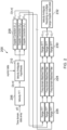
- FIG. 3 provides a schematic illustration of the data transformation in an example FFT step 306 such as the Fourier transform step of equation 7.
- a data array 312 of a frame of data received from an ADC of the radar system is illustrated on the left-hand side of Figure 3 .
- the data array is arranged with a first, fast axis 314 corresponding to the number of bits, L c , of each codeword and a second, slow axis 316 corresponding to the number of codewords, N , in the frame.
- each moving target imparts a corresponding Doppler frequency shift on the frame of radar data.
- the radar processor receives the frame of data 312 comprising the frequency shifts.
- a first phase response 318 along the first axis 314 resulting from the Doppler shift from the first target can be seen for each of the N codewords as sloping dotted lines 318 having a first gradient.
- a second phase response 320 along the first axis 314 resulting from the Doppler shift from the second target can be seen for each of the N codewords as sloping dashed lines 320 having a second gradient.
- the radar processor performs a FFT 306 along the second, slow axis 316 of the data array 312 to obtain the velocity data array 322, illustrated on the right hand side of the figure.
- the velocity data array 322 comprises a first fast axis corresponding to the first, fast axis 314 of the data array 312.
- a second axis 324 of the velocity data array 322 corresponds to a sequence of N velocity bins each corresponding to a range of target velocities. As illustrated by the figure, only the 3 rd and 7 th velocity bin of the velocity data array 322 comprise any data because these bins respectively encompass the first and second velocities of the first and second targets. In this way, by performing an FFT 306 on the data array 312 to obtain the velocity data array 322, the radar processor can separate received signals within the data frame based on their corresponding target velocity profile.
- the radar processor corrects 208 Doppler shifts in the velocity data array.
- the radar processor applies a Doppler correction by multiplying the velocity data array, S , by each one of a plurality of correction matrices, A -1 , A 0 , A 1 , to obtain a respective plurality of corrected arrays, S' -1 , S' 0 , S' 1 .
- Each correction matrix, A -1 , A 0 , A 1 corresponds to a different velocity range, as discussed further below.
- the correction (or compensation) matrices, A -1 , A 0 , A 1 can correct for phase variation along the first, fast axis of the velocity data array, resulting from the Doppler frequency shift.
- the radar processor can correct for phase variation by de-rotating the Doppler distortions over the fast-time bits / samples. Correcting for phase variation before range processing can provide range-Doppler maps having target peaks with improved sidelobe suppression.
- the first correction matrix, A 0 corresponds to a set of Doppler frequencies associated with the unambiguous velocity range.
- the radar processor can perform the Doppler compensation using predetermined knowledge of the velocity FFT output.
- the values of the first correction matrix, A 0 can be predetermined based on the unambiguous velocity range.
- Equation (10) holds for non-ambiguous targets in the velocity domain (that is targets with a velocity within the unambiguous velocity range).
- the radar processor can perform range processing to extract range information for the corrected array, S' 0 .
- the radar processor may extract the range information using a matched filtering operation in the frequency domain. Therefore, the radar processor transforms the corrected array, S 0 ' , from time-domain to frequency domain along the first, fast axis (the codeword dimension) using an FFT operation. Similarly, the radar processor transforms the transmitted codeword, c, to the frequency domain.
- the radar processor can perform range processing on the corrected array, S', to determine a Doppler compensated range-Doppler map, U 0 .
- the radar processor may perform 226 a Range FFT to transform the corrected array, S 0 ' , and the codeword, c, into the frequency domain.
- the radar processor may apply 228 a frequency domain matched filter to the frequency domain corrected array and codeword followed by a range inverse FFT (IFFT) 230 to obtain the range-Doppler map, U 0 .
- IFFT range inverse FFT
- the radar processor may extract the range information in the time-domain, instead of the frequency domain approach.
- the radar processor can perform an IFFT step (instead of a FFT) on the corrected data array along the slow axis to return to the time domain.
- the radar processor may then perform a filter-convolution using a matched filter.
- the radar processor may perform the time domain matched filtering using a sliding correlator.
- the radar processor may determine 232 a velocity of each of the one or more targets based on the Doppler compensated range-Doppler map, U.
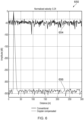
- Figures 5 to 7 illustrate a comparison of range-Doppler data produced by a radar processor using the uncompensated method of Figure 1 and the Doppler-compensated method of Figure 2 (for a single unambiguous correction matrix, A 0 ).
- Figures 5 to 7 illustrate range-Doppler data for which only the first correction matrix, A 0 , has been applied corresponding to the unambiguous velocity range [-145.5, 145.5) km/h. Ambiguous velocity resolving using a plurality of correction matrices is discussed further below in relation to Figures 8 and 9 .
- Figures 5 to 7 illustrate the improvement in sidelobe suppression of the Doppler compensated method of Figure 2 . The improvement in sidelobe suppression arises by performing Doppler correction prior to range processing.
- the range-Doppler data is illustrated for a single target having a target velocity of 70.4 km/h. The target velocity falls within the unambiguous velocity range [-145.5, 145.5) km/h.
- Figure 5 illustrates an example in which the target velocity is off-grid
- Figure 6 illustrates an example in which the target velocity is on-grid.
- An on-grid target velocity refers to a target velocity that corresponds to one of the discrete Doppler correction frequencies (equation 8) used in the correction matrix, A 0 .
- An off-grid target velocity refers to a target velocity corresponding to a frequency between two of the discrete Doppler correction frequencies.
- Both Figures 5 and 6 include a target range profile 550, 650 and range-Doppler maps 552, 652.
- the target range profiles 550, 650 illustrate the range data in the velocity bin corresponding to the target velocity of 70.4 km/h.
- the target range profiles 550, 650 illustrate uncompensated range profiles 554, 654 obtained using the uncompensated method of Figure 1 , and Doppler compensated range profiles 556, 656 obtained using the Doppler compensated method of Figure 2 .
- the Figures illustrate that the Doppler compensated range profiles 556, 656 have an improved sidelobe suppression compared to the uncompensated profiles 554, 654 for both off-grid and on-grid target velocities.
- the sidelobe suppression improves from ⁇ 38 dB to ⁇ 78 dB for the off-grid example of Figure 5 and from ⁇ 38 dB to ⁇ 330 dB for the on-grid example of Figure 6 .
- the range-Doppler maps 552, 652 include an uncompensated range-Doppler map 558, 658 and a Doppler compensated range-Doppler map 560, 660.
- the range-Doppler maps 552, 652 illustrate similar data to the target range profiles 550, 650.
- the on-grid range-Doppler map 660 illustrates that the ⁇ 330 dB sidelobe suppression is only obtained for the on-grid velocity gate corresponding to the target velocity. Adjacent velocity gates have a noise floor at ⁇ 75 dB which is a similar level to the side-lobe suppression obtained for the off-grid Doppler compensated target range profile 556.
- Figure 7 illustrates a further example in which a multiple input multiple output (MIMO) arrangement has been applied using the CDMA principle.
- MIMO multiple input multiple output
- the figure illustrates an uncompensated range-Doppler map 762 and a Doppler compensated range-Doppler map 764 for a single input single output (SISO) example where 1 transceiver is active such that 1 codeword is used.
- the figure further illustrates an uncompensated range-Doppler map 766 and a Doppler compensated range-Doppler map 768 for a MIMO example where 4 transceivers are active such that 4 unique codewords are present in the data.
- the figures illustrate that improved sidelobe suppression is obtained for both SISO and MIMO examples. This shows that the sidelobe suppression improvement is obtained for superimposed signals originating from multiple transmit antennas, hence the techniques mitigate the Doppler artefacts on both the auto- and cross-correlation properties.
- the radar processor may receive the frame of radar data as a data array from each receiver and arrange the data arrays as a data cube. Each data array may correspond to a different codeword or a single codeword arranged in a time-staggered manner.
- the radar processor may process the data cube in the same way as described above for a single data array.
- the radar processor can transform the data cube along the slow axis to obtain a velocity data cube and then correct the velocity data cube using the correction algorithm. In this way, the radar processor can correct the data from each receiver using the same correction algorithm (such as the same plurality of correction matrices).
- the radar processor may perform range processing on a corrected velocity data cube to obtain the range-Doppler map. Performing the range processing may comprise matched filtering each corrected velocity data array in the corrected velocity data cube with the respective codeword.
- the maximum unambiguous velocity, v ua is determined by the pulse repetition time and the carrier wavelength of the radar system.
- the maximum unambiguous velocity, v ua 145.5 km/h.
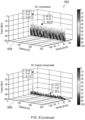
- Figure 8 illustrates an uncompensated range-Doppler map obtained by the uncompensated method of Figure 1 for three moving targets.
- the three moving targets comprise one unambiguous target with a target velocity falling inside the unambiguous velocity range [-145, 145) km/h and two ambiguous targets with respective target velocities falling outside the unambiguous velocity range.
- the three targets are defined by:
- the figure illustrates that the uncompensated method is unable to distinguish between the unambiguous and unambiguous targets.
- the range-Doppler map estimates target velocities as -51 km/h, 80 km/h and 115 km/h. Therefore, the target velocities of the first target, R 0 , and third target, R 2 , are estimated incorrectly. These two target velocities exceed the maximum unambiguous velocity
- the disclosed radar processors and methods can resolve ambiguous target velocities by applying 208 Doppler correction by applying a set of Doppler correction frequencies wherein at least one Doppler correction frequency corresponds to a velocity outside the unambiguous velocity range.
- the radar processor applies plurality of correction matrices, A -1 , A 0 , A 1 , to the velocity data array, S , prior to range processing 226, 228, 230.
- the first correction matrix, A 0 is based on a set of Doppler correction frequencies corresponding to the unambiguous velocity range.
- a second correction matrix, A -1 , and a third correction matrix, A 1 are based on respective sets of Doppler correction frequencies corresponding to velocity gates outside the unambiguous velocity range.
- the radar processor may correct for the Doppler shifts by multiplying the velocity data array, S, by each of the plurality of correction matrices, A -1 , A 0 , A 1 , to obtain a respective plurality of corrected arrays, S' -1 , S' 0 , S' 1 .
- the radar processor may then perform range processing on each of the corrected arrays, S' -1 , S' 0 , S' 1 , to obtain a respective plurality of Doppler compensated Range-Doppler maps, U -1 , U 0 , U 1 .
- the radar processor may perform range processing on each of the corrected arrays, S' -1 , S' 0 , S' 1 , in the same manner as described above for the first corrected array, S' 0 .
- the radar processor can determine 232 one or more true target velocities from the plurality of Doppler compensated Range-Doppler maps, U -1 , U 0 , U 1 .
- the radar processor effectively applies multiple hypotheses to the target velocities.
- each correction matrix is defined individually for the velocity ranges [-3 v ua , -v ua ), [- v ua , v ua ) and [ v ua , 3 v ua ), respectively.
- the radar processor applies a particular correction matrix to a target with a target velocity falling outside the velocity range of that matrix, the resulting signal to noise ratio (SNR) loss will be very high for that target.
- the radar processor compensates the target velocity with a wrongly estimated Doppler frequency according to equations 10 and 11 resulting in an extreme signal-to-noise ratio (SNR) loss for the target. Therefore, even though the target velocity may still be effectively folded back into the range, the peak is not identifiable because the application of the correction matrix destroys the peak.
- the target (ghost) peak will vanish, due to limited coherency of the incorrectly compensated signal, while only a ridge along the range profile remains along the full target's ambiguous velocity bin.
- the radar processor can effectively extend its velocity range beyond the unambiguous velocity range for a particular carrier frequency and pulse duration.
- the radar processor provides a plurality of range-Doppler maps, U -1 , U 0 , U 1 , with only the targets present in the velocity region that is desired. Therefore, velocity ambiguity is resolved the plurality of correction matrices A -1 , A 0 , A 1 .
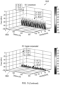
- Figure 9 illustrates a plurality of Doppler compensated range Doppler maps produced by a radar processor according to an embodiment of the present disclosure.
- the same three targets, R 0 , R 1 , R 2 are used as described above in relation to Figure 8 .
- a first range-Doppler map 972 corresponds to the first correction matrix, A 0 , and the unambiguous velocity range of [- v ua , -v ua ) [-145.5, 145.5) km/h.
- a target peak can be seen corresponding to the first target, R 0 , with a velocity of 80 km/h.
- no peaks are seen in the velocity gates corresponding to the folded velocities of the second and third targets, R 1 , R 2 , with target velocities falling outside the unambiguous range of the first correction matrix, A 0 .
- a second range-Doppler map 970 corresponds to the second correction matrix, A -1 , with a corresponding velocity range of [-3 v ua , -v ua ) [-436.5, -145.5) km/h outside the unambiguous velocity range, [- v ua , - v ua ).
- a target peak can be seen corresponding to the third target, R 2 , with a velocity of -175 km/h. No peaks are seen in the velocity gates corresponding to the folded velocities of the first and second targets, R 0 , R 1 , with target velocities falling outside the velocity range of the second correction matrix, A -1 .
- a third range-Doppler map 974 corresponds to the third correction matrix, A 1 , with an velocity range of [ v ua , 3 v ua ) [145.5, 436.5) km/h outside the unambiguous velocity range, [- v ua , - v ua ).
- a target peak can be seen corresponding to the second target, R 2 , with a velocity of 240 km/h. No peaks are seen in the velocity gates corresponding to the folded velocities of the first and third targets, R 0 , R 2 , with target velocities falling outside the velocity range of the third correction matrix, A 1 .
- the second target moving at v 1 240 km h -1 undergoes most of the peak power losses.
- the third range-Doppler map indicates that the Doppler compensation approach results in a peak power increase of 13.79 dB compared to the corresponding peak in the uncompensated range-Doppler map of Figure 8 . Therefore, the Doppler compensation of the radar processor provides increased sensitivity (due to sidelobe reduction and peak power enhancement) combined with ambiguity resolving capabilities.
- the first to third range-Doppler maps 970, 972, 974 illustrate that when a target is present in an adjacent velocity region, with respect to the velocity region of interest, range compression results in a ridge (that is likely to fall under the thermal noise floor). This results from the application of the incorrect correction matrix which has been applied as compensation for the specific target.
- the formed ridge will exceed the levels achieved for the optimally suppressed sidelobes, but may still be below the inherent, non-compensated Doppler sidelobe level (as presented in Figure 8 ).
- the peaks of the targets fall below the ridge due to incoherency with the transmitted signal.
- the range ridges in the second range Doppler map 972 fall well below the thermal noise floor, even for high SNR targets (55.9dB between peak power and noise ridge).
- the noise ridge of the two times backfolded ambiguous target can increase by approximately 30 dB. In practice, this is very unlikely to happen due to the generally short code repetition interval in PMCW/OFDM radars, hence relatively high v ua .
- the radar processor may selectively apply the plurality of correction matrices for received frames of radar data to alleviate any additional computational burden. In this way, the radar processor can acquire a-priori information on the target velocities present for a particular frame of data and then selectively apply a subset of the plurality of correction matrices for subsequent frames. The subset of correction matrices will correspond to the correction matrices with a velocity range encompassing one of the target velocities.
- the radar processor may perform an optional step of determining 210 a subset of correction matrices based on received a-priori data comprising information on the target velocities.
- the a-priori data may be received from another radar system.
- the a-priori data may be received from a memory or a register.
- the radar processor may be configured to determine the one or more target velocities for a particular frame of radar data and store the one or more target velocities in the memory as the a-priori data for use with a subsequent frame of radar data.
- the radar processor may determine a subset of correction matrices each with a corresponding set of Doppler frequencies corresponding to velocity gates encompassing the one or more target velocities. The radar processor may then correct the velocity data array with only the subset of correction matrices and not correct the velocity data array with any correction matrices not in the subset of correction matrices.
- the radar processor may selectively apply the full plurality of correction matrices (for example, the three Doppler compensation matrices, A -1 , A 0 , A 1 ) for a first frame of data.
- the radar processor can use the target velocities detected in the first frame as a-priori information for subsequent frames.
- the radar processor may receive a-priori information on the target velocities of the one or more targets from another radar system.
- the radar processor may correct a second frame of data with the subset of correction matrices (A 0 , A 1 ).
- the radar processor may determine a second velocity data array by performing a FFT on the second frame of data and multiply the second velocity data array by each correction matrix of the subset of correction matrices.
- the radar processor may determine a consolidated correction matrix based on the subset of correction matrices and multiply the second velocity data array with the consolidated correction matrix.
- the radar processor may determine a set of Doppler correction frequencies of the consolidated correction matrix by determining one or more Doppler correction frequencies in each of the subset of correction matrices that correspond to velocity gates encompassing the target velocities determined in the first frame.
- the one or more Doppler correction frequencies of the consolidated matrix may include Doppler correction frequencies adjacent to the Doppler correction frequencies encompassing the targets to allow for a change in velocity of the targets.
- the consolidated correction matrix may then comprise the one or more Doppler correction frequencies (and optionally adjacent Doppler correction frequencies) from each correction matrix of the subset of correction matrices.
- the consolidated correction matrix consists of rows that correspond with the targets' detected Doppler shifts f D ′ n , as defined in equation 10.
- the consolidated matrix comprises a set of Doppler correction frequencies corresponding to a set of velocity gates and at least one of the Doppler correction frequencies corresponds to a velocity gate outside the unambiguous velocity range.
- the radar processor may multiply the consolidated correction matrix with the second velocity data array to correct a Doppler shift of the frame.
- the radar processor may selectively apply the full plurality of correction matrices periodically, for example, once every K frames. In this way, the radar processor can update the subset of correction matrices periodically. The radar processor can then correct frames based on the subset for the intervening K-1 frames.
- a radar system may use a first codeword repetition interval for a first frame (and optionally every K frames) and a second codeword repetition interval for subsequent frames (intervening frames), wherein the first codeword repetition interval is shorter than the second codeword repetition interval.
- the first frame may have a large unambiguous velocity range and the radar processor may determine the target velocities present using the first correction matrix, A0, corresponding to the unambiguous velocity range. The target velocities can then be stored as the a-priori data.
- the radar processor may apply a correction algorithm with a set of Doppler correction frequencies corresponding to the target velocities and at least one of the set of Doppler correction frequencies may correspond to a velocity gate outside the unambiguous velocity range.
- the radar system may operate in a multimode in which initially the T CRI is small (and codeword short) to determine target velocity information. The system then switches to a mode with large T CRI (long codeword, better sensitivity) in which target velocities can become ambiguous.
- the radar processor can apply Doppler correction frequencies outside the unambiguous velocity range and use the a-priori data from the first frame to solve the ambiguities.
- the radar processor determines that there are ambiguous targets with target velocities outside the unambiguous velocity range, it can apply additional single or multiple adjusted correction matrix/matrices.
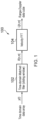
- FIG 4 illustrates a PMCW radar system 440 comprising a radar processor 442 according to the present invention.
- the radar processor may implement the method of Figure 2 or any other methods according to embodiments of the present disclosure.
- the PMCW radar system 440 comprises the radar processor 442 and a transceiver 448.
- the transceiver 448 may be an RF transceiver and transmit frames of radar data via an antenna.
- the radar data may comprise the sequence of N codewords as described above.
- the radar processor 442 may generate a digital signal corresponding to the frames of radar data and pass it to a digital to analogue converter (DAC) 444.
- the DAC 444 can convert the digital signal to an analogue signal for transmission by the transceiver as an RF signal.
- the transmitted frames may reflect off one or more targets (not illustrated) and return to the radar system 440. Any targets moving at a velocity relative to the radar system 440 will impart a Doppler frequency shift on the transmitted frame dependent on the velocity.
- the transceiver 448 may receive the reflected frames of radar data via the antenna and pass the received analogue signal to an ADC 446.
- the ADC 446 may convert the analogue signal to a digital received signal, y.
- the radar processor 442 may receive the frame of radar data from the ADC 446. The radar processor 442 may then process the radar data as described above.
- the radar system 440 and radar processor 442 may receive a frame of radar data transmitted by another antenna in a multiple antenna arrangement such as a code-division multiple access (CDMA) set up.
- CDMA code-division multiple access
- the disclosed radar processor and signal processing techniques can be applied in all radar systems.
- FMCW radar systems the disclosed processor can provide a solution to reduce the range-velocity coupling.
- DMR digitally modulated radar
- OFDM orthogonal frequency division multiplexing
- OTFS orthogonal time frequency space
- the disclosed processor and methods may correct for the Doppler distortions that those radar sensors are typically sensitive to. Therefore, the disclosed embodiments are suitable for NextGen DMR radar sensors.
- the disclosed radar processor and method is particularly suitable for PMCW radars, or any alternative radar signal, that is characterized by the repeated transmission of a waveform within a measurement frame.
- the compensation technique is non-iterative, scenario-independent and also provides velocity ambiguity resolving.
- the radar processor and method first extract the velocity profiles, followed by the range profiles. This approach allows for de-rotating the phase evolution along the fast time samples from the estimated velocity profiles. After this correction, range processing is performed to produce the range-Doppler map.
- the disclosed radar processor can correct Doppler shifts caused by objects moving within the unambiguous velocity range and can be extended by parallel use of correction matrices that correspond to velocities beyond the unambiguous velocity range.
- one or more correction matrices can be used in parallel in order to detect objects moving with ambiguous velocities.
- a Phase-Modulated Continuous Wave (PMCW) RADAR transmits digital codes, that are intrinsically highly intolerant to Doppler shifts.
- the disclosed radar processors can perform a non-iterative and scenario-independent technique that significantly decreases the Doppler-induced performance degradation.
- additional processing power may be provided to maintain an update rate or increase the latency to compensate all data being collected before range processing commences.
- the set of instructions/method steps described above are implemented as functional and software instructions embodied as a set of executable instructions which are effected on a computer or machine which is programmed with and controlled by said executable instructions. Such instructions are loaded for execution on a processor (such as one or more CPUs).
- processor includes microprocessors, microcontrollers, processor modules or subsystems (including one or more microprocessors or microcontrollers), or other control or computing devices.
- a processor can refer to a single component or to plural components.
- the set of instructions/methods illustrated herein and data and instructions associated therewith are stored in respective storage devices, which are implemented as one or more non-transient machine or computer-readable or computer-usable storage media or mediums.
- Such computer-readable or computer usable storage medium or media is (are) considered to be part of an article (or article of manufacture).
- An article or article of manufacture can refer to any manufactured single component or multiple components.
- the non-transient machine or computer usable media or mediums as defined herein excludes signals, but such media or mediums may be capable of receiving and processing information from signals and/or other transient mediums.
- Example embodiments of the material discussed in this specification can be implemented in whole or in part through network, computer, or data based devices and/or services. These may include cloud, internet, intranet, mobile, desktop, processor, look-up table, microcontroller, consumer equipment, infrastructure, or other enabling devices and services. As may be used herein and in the claims, the following non-exclusive definitions are provided.
- one or more instructions or steps discussed herein are automated.
- the terms automated or automatically mean controlled operation of an apparatus, system, and/or process using computers and/or mechanical/electrical devices without the necessity of human intervention, observation, effort and/or decision.
- any components said to be coupled may be coupled or connected either directly or indirectly.
- additional components may be located between the two components that are said to be coupled.
Landscapes
- Engineering & Computer Science (AREA)
- Radar, Positioning & Navigation (AREA)
- Remote Sensing (AREA)
- Physics & Mathematics (AREA)
- Computer Networks & Wireless Communication (AREA)
- General Physics & Mathematics (AREA)
- Spectroscopy & Molecular Physics (AREA)
- Radar Systems Or Details Thereof (AREA)
Description
- The present disclosure relates to a radar processor for processing radar data.
-
WO 2018/115370 A1 describes an automotive spread MIMO-configured radar system comprising a plurality of transceiver antenna units for transmitting mutually orthogonal radar waves and, for each transceiver antenna unit, a plurality of range gates to indicate a range detected by the transceiver antenna unit. -
US 2018/0231652 A1 describes a radar sensing system with a receiver configured for installation and use on the vehicle that is able to receive radio signals that include transmitted radio signals reflected from objects in the environment. A processor samples the received radio signals to produce a sampled stream. The processor processes the sampled stream such that the sampled stream is correlated with various delayed versions of a baseband signal. The correlations are used to determine an improved range, velocity, and angle of targets in the environment. - According to a first aspect of the present disclosure there is provided a radar processor for processing a frame of radar data received from one or more targets, the frame of radar data having a carrier frequency and comprising a sequence of codewords with a codeword repetition interval, wherein the carrier frequency and the codeword repetition interval define an unambiguous velocity range, the radar processor configured to:
- receive the frame of radar data;
- transform the frame to obtain a velocity data array;
- apply a correction algorithm to the velocity data array to correct a Doppler shift of the frame to obtain a corrected array, wherein the correction algorithm comprises a set of Doppler correction frequencies corresponding to a set of velocity gates and at least one Doppler correction frequency corresponds to a velocity gate outside the unambiguous velocity range; and
- perform range processing on the corrected array to obtain a range-Doppler map.
- In one or more embodiments, the radar processor may be further configured to determine a velocity of each of the one or more targets based on the range-Doppler map.
- In one or more embodiments, the correction algorithm may comprise a plurality of correction matrices, each correction matrix corresponding to a different set of Doppler correction frequencies each with an associated velocity range. The radar processor may be configured to:
- apply the correction algorithm by multiplying the velocity data array with each one of the plurality of correction matrices to obtain a plurality of respective corrected arrays; and
- perform range processing on the plurality of corrected arrays to obtain the range-Doppler map.
- In one or more embodiments, the radar processor may be configured to receive the a-priori data from a second radar processor.
- In one or more embodiments, the radar processor may be further configured to:
- determine a velocity of each of the one or more targets based on the range-Doppler map for the frame of data;
- determine a subset of correction matrices comprising correction matrices with a velocity range encompassing one or more of the velocities of each of the one or more targets;
- receive a second frame of time-domain radar data;
- transform the second frame to obtain a second velocity data array;
- correct the second velocity data array based on the subset of correction matrices to obtain one or more second corrected arrays;
- perform range processing on the one or more second corrected arrays to obtain a second range-Doppler map.
- In one or more embodiments, the radar processor may be configured to multiply the second velocity data array with each one of the subset of correction matrices to obtain the one or more second corrected arrays.
- In one or more embodiments, the radar processor may be configured to determine a consolidated correction matrix based on the subset of correction matrices;
- multiply the second velocity data array with the consolidated correction matrix to obtain a consolidated second corrected array; and
- perform range processing on the consolidated second corrected array to obtain the second range-Doppler map.
- In one or more embodiments, the radar processor may be configured to:
- receive a third frame of time-domain radar data;
- transform the third frame to obtain a third velocity data array;
- multiply the velocity data array with each one of the plurality of correction matrices, to obtain a plurality of respective third corrected arrays;
- perform range processing on the plurality of third corrected arrays to obtain a third range-Doppler map;
- determine a velocity of each of the one or more targets based on the third range-Doppler map for the third frame of data; and
- update the subset of correction matrices comprising correction matrices with a velocity range encompassing one or more of the velocities of each of the one or more targets.
- In one or more embodiments, the frame of radar data may be a phase modulated continuous wave, PMCW, frame of radar data and the radar processor is suitable for use in a PMCW radar system.
- In one or more embodiments, the radar processor may be configured to receive the frame of radar data from a plurality of receivers in a multiple input multiple output, MIMO, radar system arrangement.
- According to a second aspect of the present disclosure, there is provided a radar system comprising any radar processor disclosed herein.
- In one or more embodiments, the radar system may be an automotive radar system.
- According to a further aspect of the present disclosure, there is provided a method for processing a frame of radar data received from one or more targets, the frame of radar data having a carrier frequency and comprising a sequence of codewords with a codeword repetition interval, wherein the carrier frequency and the codeword repetition interval define an unambiguous velocity range, the method comprising:
- receiving the frame of radar data;
- transforming the frame to obtain a velocity data array;
- applying a correction algorithm to the velocity data array to correct a Doppler shift of the frame to obtain a corrected array, wherein applying the correction algorithm comprises applying a set of Doppler correction frequencies corresponding to a set of velocity gates, wherein at least one Doppler correction frequency corresponds to a velocity gate outside the unambiguous velocity range; and
- performing range processing on the corrected array to obtain a range-Doppler map.
- The figures and Detailed Description that follow also exemplify various example embodiments. Various example embodiments may be more completely understood in consideration of the following Detailed Description in connection with the accompanying Drawings.
- One or more embodiments will now be described by way of example only with reference to the accompanying drawings in which:
-
Figure 1 illustrates a method for processing received radar data by a radar processor of a PMCW radar system; -
Figure 2 illustrates a method for processing radar data received from one or more targets by a radar processor of a PMCW radar system according to the present invention; -
Figure 3 provides a schematic illustration of the data transformation in an example FFT step; -
Figure 4 illustrates a PMCW radar system comprising a radar processor according to the present invention; -
Figure 5 illustrates a first example comparison of range-Doppler data produced by a radar processor using the uncompensated method ofFigure 1 and the Doppler-compensated method ofFigure 2 ; -
Figure 6 illustrates a second example comparison of range-Doppler data produced by a radar processor using the uncompensated method ofFigure 1 and the Doppler-compensated method ofFigure 2 ; -
Figure 7 illustrates a third example comparison of range-Doppler data produced by a radar processor using the uncompensated method ofFigure 1 and the Doppler-compensated method ofFigure 2 ; -
Figure 8 illustrates an uncompensated range-Doppler map obtained by the uncompensated method ofFigure 1 for three moving targets; and -
Figure 9 illustrates a plurality of Doppler compensated range Doppler maps produced by a radar processor according to an embodiment of the present disclosure. - Automotive radars are sensors that are able to extract range, velocity and azimuthal/elevational angle information of multiple objects (or targets) by transmitting and receiving radio-frequency (RF) electromagnetic waves. Although the measurement frames of the sensors are of short time duration, rapidly changing scenarios can highly affect the radar's performance. Doppler frequency shifts are known to distort radar waveforms, while each waveform shows different tolerance to the Doppler frequency shifts. Frequency-Modulated Continuous Wave (FMCW) radars are known for their robustness against Doppler. On the other hand, Phase-Modulated Continuous Wave (PMCW) radars may be less tolerant to artefacts arising from Doppler shifts. In radar, correction for the individual Doppler-shifted waveforms can be complex because reflections may be received from all target objects simultaneously. The present disclosure provides a radar processor and method for processing radar data to correct for Doppler shifts in a way that is more tolerant to Doppler shifts including for PMCW radars. The disclosed radar processor can advantageously correct for Doppler shifts corresponding to velocities that fall both inside and outside an unambiguous velocity range.
- A PMCW radar can transmit codeword(s) that feature (nearly-)perfect auto- and cross-correlation sidelobes in order to achieve sufficient dynamic range. Examples of code families that exhibit these exceptional properties are the Almost Perfect Autocorrelation Sequences (APAS) or Zero-Correlation Zone (ZCZ) sequences. In radar, dynamic range is a crucial aspect that should be in the range of 80-90 dB to avoid target masking (similar to near-far problem in communication, but more extreme).
- The nearly-perfect correlation properties of the above-mentioned sequences can deteriorate the radar performance significantly when they are exposed to a moving target. The Doppler frequency shift resulting from the moving target can impact the sequences within a single code and destroy the zero-sidelobe behaviour.
- A received radar signal may be considered as a transmitted waveform x(t) that is reflected from K targets, where each target at distance Rk is moving at constant velocity vk, which respectively induces a round-trip delay τk which is assumed to be constant for the duration of the waveform and Doppler frequency shift fD,k (narrowband assumption). Then, the received signal, y(t), can be denoted as:

- Here, the Doppler shift equals fD,k = 2vk /λ, where λ is the wavelength of the carrier.
-
Figure 1 illustrates amethod 100 for processing received radar data by a radar processor of a PMCW radar system. - The radar processor may receive a time domain data array. The time domain data array may comprise the received signal, y, arranged in a 2-dimensional array with a first (fast) axis corresponding to a symbol or sample of a transmitted codeword, c, and a second (slow) axis corresponding to a number, N, of transmitted codewords (or consecutively transmitted codewords). The radar processor may receive the received signal y from an output of an analog-to-digital converter (ADC).
- At
step 102, the radar processor can first apply a time-domain matched filter (sliding window) to get the distance to the targets:
- At
step 104, the radar processor can estimate the Doppler frequencies using a Fast Fourier Transform (FFT), since the phase shift between the consecutively transmitted codewords (referred to as slow-time samples) of the kth target reflection can be denoted as:
- The kth target reflection experiences a phase behaviour that is linear with its velocity. A linear phase increase or decrease manifests itself as a frequency, which can be efficiently calculated by a Fast Fourier transform over the slow-time period to provide a range-Doppler map, U[n,m]:

- The
method 100 ofFigure 1 can result in unsatisfactory sidelobe level appearance or amplification. As discussed further below, themethod 100 may also identify targets with a velocity falling outside an unambiguous velocity range (defined by the radar system) as having a velocity within the unambiguous velocity range due to velocity aliasing or velocity folding. For a particular frame of radar data, the unambiguous velocity range is defined by a carrier frequency of the frame and the codeword repetition interval, TCRI, of a sequence of codewords within the frame. The unambiguous velocity range is a term well known in the art and corresponds to ±vua, a maximum unambiguous radial velocity of a target relative to the radar processor or radar system. The maximum unambiguous radial velocity, vua , is defined by the codeword repetition time TCRI of the PMCW radar:
- The code repetition interval, TCRI, may be considered as the sampling period of the linear phase in equation (3). If TCRI is too large, relative to a target velocity, the target is under sampled and phase changes larger than +/-n may be obtained. These phase changes cannot be distinguished from phase changes that are smaller than +/- n. The resulting ambiguity is referred to as velocity aliasing.
- Selection of the codeword repetition interval typically comprises a trade-off between maximising the unambiguous velocity range by using short codeword repetition intervals and maximising the unambiguous distance or other code related properties, such as the code set size (relating to the number of simultaneous transmit antennas), the zero-correlation widths / sidelobe behaviour, by using long codeword repetition intervals. The unambiguous distance is defined by the following equation:

- One or more example radar processors and methods disclosed herein can overcome this trade-off by detecting targets with target velocities falling outside the unambiguous velocity range. Furthermore, examples of the present disclosure provide improved sidelobe suppression by performing Doppler shift correction prior to range processing.
-
Figure 2 illustrates amethod 200 for processing radar data received from one or more targets by a radar processor of a PMCW radar system according to an embodiment of the present disclosure. - The method comprises the radar processor: receiving a frame of radar data, y(t), the frame of radar data having a carrier frequency and comprising a sequence of codewords, wherein the carrier frequency and the codeword repetition interval define an unambiguous velocity range; transforming 206 the frame to obtain a velocity data array, S[n,m]; applying 208 a correction algorithm, A, to the velocity data array to correct a Doppler shift of the frame (resulting from target velocities of the one or more targets relative to the radar processor) to obtain a corrected array, S'[n,m], wherein applying the correction algorithm comprises correcting the velocity data array with a set of Doppler correction frequencies corresponding to a set of velocity gates, wherein at least one Doppler correction frequency corresponds to a velocity gate outside the unambiguous velocity range; and performing 226, 228, 230 range processing on the corrected array, S'[n,m], to obtain a range-Doppler map, U.
- By including at least one Doppler correction frequency corresponding to a velocity gate outside the unambiguous velocity range, the radar processor can detect target velocities with ambiguous velocities falling outside the unambiguous velocity range. In particular, the Doppler corrected range-Doppler map, U, is extended beyond the unambiguous velocity range where conventionally ambiguous targets can be identified.
- In the illustrated example, the radar processor applies the correction algorithm by multiplying 208 the velocity data array, S[n,m], with each one of a plurality of correction matrices, A-1, A0, A1, to obtain a respective plurality of corrected arrays, S' -1 , S'0 , S'1 . Each correction matrix, A-1, A0, A1, may correspond to a different set of Doppler correction frequencies each with a corresponding velocity range. The set of Doppler correction frequencies for a first correction matrix, A0, may correspond to the unambiguous velocity range and the set of Doppler correction frequencies for a second correction matrix, A-1, A1, may correspond to an ambiguous velocity range outside the unambiguous velocity range. The method may comprise performing 226, 228, 230 range processing on each of the plurality of corrected arrays, S'-1, S'0 , S'1, to obtain a respective plurality of range-Doppler maps, U-1, U0, U1. The plurality of range-Doppler maps, U-1, U0, U1, may form a single range-Doppler map, U.
- The PMCW radar system may transmit and receive the frame of radar data. As discussed in relation to
Figure 1 , the radar processor may receive a frame of time-domain radar data, y(t), as a data array, Y. The data array, Y, may comprise the received signal, y(t), arranged in a 2-dimensional array with a first (fast) axis corresponding to a symbol or sample of a transmitted codeword, c, and a second (slow) axis corresponding to a number, N, of transmitted codewords (or consecutively transmitted codewords) in the frame. In some examples, the method may comprise the radar processor arranging the received signal, y(t), as the data array, Y. In some examples, the radar processor may receive the radar data from multiple receivers and arrange the data array as a data cube. The radar processor may receive the received signal, y(t), from an output of an analog-to-digital converter (ADC). - In some examples, the transmitted codewords within the frame may be identical, to enable construction of the data array, Y. In some examples, the radar system may carry out low-rate communication by changing codewords (for multiple transmitters) on a frame-to-frame basis.
- After the radar processor receives all time-domain ADC data for the frame, the radar processor transforms 206 the frame to obtain a velocity data array, S. In this way, the radar processor can extract the velocities of all targets in the received data. In this example, the radar processor obtains the velocity data array, S, by taking an FFT along the second (slow-time) axis of the data array (corresponding to consecutively transmitted codewords). The FFT process can be written mathematically as:

-
Figure 3 provides a schematic illustration of the data transformation in anexample FFT step 306 such as the Fourier transform step ofequation 7. - A
data array 312 of a frame of data received from an ADC of the radar system is illustrated on the left-hand side ofFigure 3 . The data array is arranged with a first,fast axis 314 corresponding to the number of bits, Lc , of each codeword and a second,slow axis 316 corresponding to the number of codewords, N, in the frame. - In this example there are two moving targets: a first moving target moving at a first velocity, v1, and a second moving target moving at a second velocity, v2. Each moving target imparts a corresponding Doppler frequency shift on the frame of radar data. The radar processor receives the frame of
data 312 comprising the frequency shifts. - A
first phase response 318 along thefirst axis 314 resulting from the Doppler shift from the first target can be seen for each of the N codewords as sloping dottedlines 318 having a first gradient. Asecond phase response 320 along thefirst axis 314 resulting from the Doppler shift from the second target can be seen for each of the N codewords as sloping dashedlines 320 having a second gradient. - The radar processor performs a
FFT 306 along the second,slow axis 316 of thedata array 312 to obtain thevelocity data array 322, illustrated on the right hand side of the figure. Thevelocity data array 322 comprises a first fast axis corresponding to the first,fast axis 314 of thedata array 312. Asecond axis 324 of thevelocity data array 322 corresponds to a sequence of N velocity bins each corresponding to a range of target velocities. As illustrated by the figure, only the 3rd and 7th velocity bin of thevelocity data array 322 comprise any data because these bins respectively encompass the first and second velocities of the first and second targets. In this way, by performing anFFT 306 on thedata array 312 to obtain thevelocity data array 322, the radar processor can separate received signals within the data frame based on their corresponding target velocity profile. - Returning to
Figure 2 , following performance of theFFT 206, the radar processor corrects 208 Doppler shifts in the velocity data array. In this example, the radar processor applies a Doppler correction by multiplying the velocity data array, S, by each one of a plurality of correction matrices, A-1, A0, A1, to obtain a respective plurality of corrected arrays, S'-1, S'0 , S'1 . Each correction matrix, A-1, A0, A1, corresponds to a different velocity range, as discussed further below. The correction (or compensation) matrices, A-1, A0, A1, can correct for phase variation along the first, fast axis of the velocity data array, resulting from the Doppler frequency shift. In this way, the radar processor can correct for phase variation by de-rotating the Doppler distortions over the fast-time bits / samples. Correcting for phase variation before range processing can provide range-Doppler maps having target peaks with improved sidelobe suppression. - We first consider the correction of the velocity data array for unambiguous targets having velocities within the unambiguous velocity range to illustrate the improvement of sidelobe suppression of the Doppler compensated method of
Figure 2 relative to the uncompensated method ofFigure 1 . Such unambiguous targets can be corrected by applying the first correction matrix, A0. The correction of the velocity data array for targets having a velocity outside the unambiguous velocity range through application of Doppler frequencies corresponding to velocity gates outside the unambiguous velocity range, is discussed further below in relation toFigure 9 . - The first correction matrix, A0, corresponds to a set of Doppler frequencies associated with the unambiguous velocity range. The radar processor can perform the Doppler compensation using predetermined knowledge of the velocity FFT output. In other words, the values of the first correction matrix, A0, can be predetermined based on the unambiguous velocity range. By definition of the FFT (-π ≤ ω < π), the unambiguous set of Doppler frequencies (unambiguously normalized estimated frequency range) corresponding to each of the velocity gates in the unambiguous velocity range is:

- Every individual estimated Doppler frequency corresponds to an independent phase evolution over the fast-axis samples, which can be defined as:

- Combining Equations (8) and (9), can provide the Doppler-induced phase change on the slow-time and fast-time axes, respectively, to provide the first compensation matrix, A0, as:

- Equation (10) holds for non-ambiguous targets in the velocity domain (that is targets with a velocity within the unambiguous velocity range). The radar processor can correct the velocity data array, S, by applying an element-wise matrix multiplication with the compensation matrix, A0 , to obtain a respective corrected array, S0':

- Following
determination 208 of the corrected array, S'0 , the radar processor can perform range processing to extract range information for the corrected array, S'0 . - In some examples, the radar processor may extract the range information using a matched filtering operation in the frequency domain. Therefore, the radar processor transforms the corrected array, S0', from time-domain to frequency domain along the first, fast axis (the codeword dimension) using an FFT operation. Similarly, the radar processor transforms the transmitted codeword, c, to the frequency domain.
- In this way, the radar processor can perform range processing on the corrected array, S', to determine a Doppler compensated range-Doppler map, U0. The radar processor may perform 226 a Range FFT to transform the corrected array, S0', and the codeword, c, into the frequency domain. The radar processor may apply 228 a frequency domain matched filter to the frequency domain corrected array and codeword followed by a range inverse FFT (IFFT) 230 to obtain the range-Doppler map, U0. The steps of performing this cyclic correlation in the frequency domain can be written as:

- In other examples, the radar processor may extract the range information in the time-domain, instead of the frequency domain approach. In such examples, the radar processor can perform an IFFT step (instead of a FFT) on the corrected data array along the slow axis to return to the time domain. The radar processor may then perform a filter-convolution using a matched filter. The radar processor may perform the time domain matched filtering using a sliding correlator.
- The radar processor may determine 232 a velocity of each of the one or more targets based on the Doppler compensated range-Doppler map, U.
-
Figures 5 to 7 illustrate a comparison of range-Doppler data produced by a radar processor using the uncompensated method ofFigure 1 and the Doppler-compensated method ofFigure 2 (for a single unambiguous correction matrix, A0).Figures 5 to 7 illustrate range-Doppler data for which only the first correction matrix, A0, has been applied corresponding to the unambiguous velocity range [-145.5, 145.5) km/h. Ambiguous velocity resolving using a plurality of correction matrices is discussed further below in relation toFigures 8 and9 .Figures 5 to 7 illustrate the improvement in sidelobe suppression of the Doppler compensated method ofFigure 2 . The improvement in sidelobe suppression arises by performing Doppler correction prior to range processing. - In
Figures 5 and6 , a PMCW waveform is constructed using an APAS sequence of length Lc = 2586 with N = 256 codes being repetitively transmitted. The compensation is independent of the codeword being applied. The range-Doppler data is illustrated for a single target having a target velocity of 70.4 km/h. The target velocity falls within the unambiguous velocity range [-145.5, 145.5) km/h.Figure 5 illustrates an example in which the target velocity is off-grid andFigure 6 illustrates an example in which the target velocity is on-grid. An on-grid target velocity refers to a target velocity that corresponds to one of the discrete Doppler correction frequencies (equation 8) used in the correction matrix, A0. An off-grid target velocity refers to a target velocity corresponding to a frequency between two of the discrete Doppler correction frequencies. - Both
Figures 5 and6 include atarget range profile Doppler maps Figure 1 , and Doppler compensatedrange profiles Figure 2 . The Figures illustrate that the Doppler compensatedrange profiles uncompensated profiles Figure 5 and from ~38 dB to ~ 330 dB for the on-grid example ofFigure 6 . - The range-
Doppler maps Doppler map Doppler map Doppler maps range Doppler map 660 also includes data from a velocity gate (v=71.61 km/h) adjacent to the target velocity gate (v=71.47 km/h). The on-grid range-Doppler map 660 illustrates that the ~330 dB sidelobe suppression is only obtained for the on-grid velocity gate corresponding to the target velocity. Adjacent velocity gates have a noise floor at ~ 75 dB which is a similar level to the side-lobe suppression obtained for the off-grid Doppler compensatedtarget range profile 556. -
Figure 7 illustrates a further example in which a multiple input multiple output (MIMO) arrangement has been applied using the CDMA principle. A ZCZ sequence is used with a sequence length of Lc = 2048 and number of transmitted codewords N = 256. - The figure illustrates an uncompensated range-
Doppler map 762 and a Doppler compensated range-Doppler map 764 for a single input single output (SISO) example where 1 transceiver is active such that 1 codeword is used. The figure further illustrates an uncompensated range-Doppler map 766 and a Doppler compensated range-Doppler map 768 for a MIMO example where 4 transceivers are active such that 4 unique codewords are present in the data. The figures illustrate that improved sidelobe suppression is obtained for both SISO and MIMO examples. This shows that the sidelobe suppression improvement is obtained for superimposed signals originating from multiple transmit antennas, hence the techniques mitigate the Doppler artefacts on both the auto- and cross-correlation properties. - In a MIMO example, the radar processor may receive the frame of radar data as a data array from each receiver and arrange the data arrays as a data cube. Each data array may correspond to a different codeword or a single codeword arranged in a time-staggered manner. The radar processor may process the data cube in the same way as described above for a single data array. The radar processor can transform the data cube along the slow axis to obtain a velocity data cube and then correct the velocity data cube using the correction algorithm. In this way, the radar processor can correct the data from each receiver using the same correction algorithm (such as the same plurality of correction matrices). The radar processor may perform range processing on a corrected velocity data cube to obtain the range-Doppler map. Performing the range processing may comprise matched filtering each corrected velocity data array in the corrected velocity data cube with the respective codeword.
- As described above (equation 5), the maximum unambiguous velocity, vua , is determined by the pulse repetition time and the carrier wavelength of the radar system. For a radar system configured with a code repetition interval, TCRI = 23.5 µs and a carrier frequency, fc = 79 GHz, the maximum unambiguous velocity, vua = 145.5 km/h.
-
Figure 8 illustrates an uncompensated range-Doppler map obtained by the uncompensated method ofFigure 1 for three moving targets. The three moving targets comprise one unambiguous target with a target velocity falling inside the unambiguous velocity range [-145, 145) km/h and two ambiguous targets with respective target velocities falling outside the unambiguous velocity range. The targets are arranged at the same distance having the same radar cross section, RCS = 10 dBm2. The three targets are defined by: - R 0 = 20m, v 0 = 80 km h -1
- R 1 = 20m, v 1 = 240 km h -1
- R 2 = 20m, v 2 = -175 km h -1
- The figure illustrates that the uncompensated method is unable to distinguish between the unambiguous and unambiguous targets. The range-Doppler map estimates target velocities as -51 km/h, 80 km/h and 115 km/h. Therefore, the target velocities of the first target, R0, and third target, R2, are estimated incorrectly. These two target velocities exceed the maximum unambiguous velocity |vk | > vua and their true velocities fold back into the unambiguous velocity range. As expected, all three targets are detected with relatively high range sidelobes of ~ 30dB below the peak level.
- Returning to
figure 2 , the disclosed radar processors and methods can resolve ambiguous target velocities by applying 208 Doppler correction by applying a set of Doppler correction frequencies wherein at least one Doppler correction frequency corresponds to a velocity outside the unambiguous velocity range. In the example ofFigure 2 , the radar processor applies plurality of correction matrices, A-1, A0, A1, to the velocity data array, S, prior torange processing range processing - By applying a plurality of correction matrices, A-1, A0, A1, the radar processor effectively applies multiple hypotheses to the target velocities. The plurality of correction matrices, A-1, A0, A1, correspond to differing velocity ranges as follows:


- Therefore, each correction matrix is defined individually for the velocity ranges [-3vua, -vua ), [-vua, vua ) and [vua , 3vua ), respectively.
- When the radar processor applies a particular correction matrix to a target with a target velocity falling outside the velocity range of that matrix, the resulting signal to noise ratio (SNR) loss will be very high for that target. In other words, the radar processor compensates the target velocity with a wrongly estimated Doppler frequency according to
equations 10 and 11 resulting in an extreme signal-to-noise ratio (SNR) loss for the target. Therefore, even though the target velocity may still be effectively folded back into the range, the peak is not identifiable because the application of the correction matrix destroys the peak. The target (ghost) peak will vanish, due to limited coherency of the incorrectly compensated signal, while only a ridge along the range profile remains along the full target's ambiguous velocity bin. As a result, only targets with their true target velocity within the specific velocity range of a correction matrix can be detected using that correction matrix. By applying multiple correction matrices, the radar processor can effectively extend its velocity range beyond the unambiguous velocity range for a particular carrier frequency and pulse duration. The radar processor provides a plurality of range-Doppler maps, U-1, U0, U1, with only the targets present in the velocity region that is desired. Therefore, velocity ambiguity is resolved the plurality of correction matrices A-1, A0, A1. -
Figure 9 illustrates a plurality of Doppler compensated range Doppler maps produced by a radar processor according to an embodiment of the present disclosure. The same three targets, R0, R1, R2 are used as described above in relation toFigure 8 . - A first range-
Doppler map 972 corresponds to the first correction matrix, A0, and the unambiguous velocity range of [-vua , -vua ) [-145.5, 145.5) km/h. A target peak can be seen corresponding to the first target, R0, with a velocity of 80 km/h. Unlike the range-Doppler map ofFigure 8 with the same unambiguous velocity range, no peaks are seen in the velocity gates corresponding to the folded velocities of the second and third targets, R1, R2, with target velocities falling outside the unambiguous range of the first correction matrix, A0. - A second range-
Doppler map 970 corresponds to the second correction matrix, A-1, with a corresponding velocity range of [-3vua, -vua ) [-436.5, -145.5) km/h outside the unambiguous velocity range, [-vua , -vua ). A target peak can be seen corresponding to the third target, R2, with a velocity of -175 km/h. No peaks are seen in the velocity gates corresponding to the folded velocities of the first and second targets, R0, R1, with target velocities falling outside the velocity range of the second correction matrix, A-1. - A third range-
Doppler map 974 corresponds to the third correction matrix, A1, with an velocity range of [vua, 3vua ) [145.5, 436.5) km/h outside the unambiguous velocity range, [-v ua, -vua ). A target peak can be seen corresponding to the second target, R2, with a velocity of 240 km/h. No peaks are seen in the velocity gates corresponding to the folded velocities of the first and third targets, R0, R2, with target velocities falling outside the velocity range of the third correction matrix, A1. - The second target moving at v 1 = 240 km h -1 undergoes most of the peak power losses. The third range-Doppler map indicates that the Doppler compensation approach results in a peak power increase of 13.79 dB compared to the corresponding peak in the uncompensated range-Doppler map of
Figure 8 . Therefore, the Doppler compensation of the radar processor provides increased sensitivity (due to sidelobe reduction and peak power enhancement) combined with ambiguity resolving capabilities. - The first to third range-
Doppler maps Figure 8 ). However, the peaks of the targets fall below the ridge due to incoherency with the transmitted signal. For example, the range ridges in the secondrange Doppler map 972 fall well below the thermal noise floor, even for high SNR targets (55.9dB between peak power and noise ridge). - However, in the presence of at least two targets in two non-consecutive velocity ranges, e.g.[(2n - 1) · vua , (2n + 1) · vua ) and [(2n + 1) · vua , (2n + 3) · vua ) with n being any integer number (as shown in the illustrated example n = 2 and the second and third targets at 240 km/h and -175 km/h, respectively), the noise ridge of the two times backfolded ambiguous target can increase by approximately 30 dB. In practice, this is very unlikely to happen due to the generally short code repetition interval in PMCW/OFDM radars, hence relatively high vua.
- Performing Doppler compensation with the plurality of correction matrices to enable ambiguity resolving may require duplicate processing steps compared to the uncompensated range-Doppler processing of
Figure 1 . Therefore, in one or more examples, the radar processor may selectively apply the plurality of correction matrices for received frames of radar data to alleviate any additional computational burden. In this way, the radar processor can acquire a-priori information on the target velocities present for a particular frame of data and then selectively apply a subset of the plurality of correction matrices for subsequent frames. The subset of correction matrices will correspond to the correction matrices with a velocity range encompassing one of the target velocities. - Referring back to
Figure 2 , the radar processor may perform an optional step of determining 210 a subset of correction matrices based on received a-priori data comprising information on the target velocities. In some examples, the a-priori data may be received from another radar system. In other examples, the a-priori data may be received from a memory or a register. The radar processor may be configured to determine the one or more target velocities for a particular frame of radar data and store the one or more target velocities in the memory as the a-priori data for use with a subsequent frame of radar data. Following receipt of the a-priori data, the radar processor may determine a subset of correction matrices each with a corresponding set of Doppler frequencies corresponding to velocity gates encompassing the one or more target velocities. The radar processor may then correct the velocity data array with only the subset of correction matrices and not correct the velocity data array with any correction matrices not in the subset of correction matrices. - In one example, the radar processor may selectively apply the full plurality of correction matrices (for example, the three Doppler compensation matrices, A-1, A0, A1) for a first frame of data. The radar processor can then determine the target velocities present (for example R0 = 80 km/h and R1 = 240 km/h) based on the range-Doppler map for the first frame and determine the subset of the plurality of correction matrices (in this example, A0 and A1) with velocity ranges encompassing the detected target velocities. In this way, the radar processor can use the target velocities detected in the first frame as a-priori information for subsequent frames. In other examples, the radar processor may receive a-priori information on the target velocities of the one or more targets from another radar system.
- The radar processor may correct a second frame of data with the subset of correction matrices (A0, A1). In one example, the radar processor may determine a second velocity data array by performing a FFT on the second frame of data and multiply the second velocity data array by each correction matrix of the subset of correction matrices. In other examples, the radar processor may determine a consolidated correction matrix based on the subset of correction matrices and multiply the second velocity data array with the consolidated correction matrix. The radar processor may determine a set of Doppler correction frequencies of the consolidated correction matrix by determining one or more Doppler correction frequencies in each of the subset of correction matrices that correspond to velocity gates encompassing the target velocities determined in the first frame. The one or more Doppler correction frequencies of the consolidated matrix may include Doppler correction frequencies adjacent to the Doppler correction frequencies encompassing the targets to allow for a change in velocity of the targets. The consolidated correction matrix may then comprise the one or more Doppler correction frequencies (and optionally adjacent Doppler correction frequencies) from each correction matrix of the subset of correction matrices. As a result, the consolidated correction matrix consists of rows that correspond with the targets' detected Doppler shifts

equation 10. In this way, the consolidated matrix comprises a set of Doppler correction frequencies corresponding to a set of velocity gates and at least one of the Doppler correction frequencies corresponds to a velocity gate outside the unambiguous velocity range. The radar processor may multiply the consolidated correction matrix with the second velocity data array to correct a Doppler shift of the frame. - The radar processor may selectively apply the full plurality of correction matrices periodically, for example, once every K frames. In this way, the radar processor can update the subset of correction matrices periodically. The radar processor can then correct frames based on the subset for the intervening K-1 frames.
- In some examples, a radar system may use a first codeword repetition interval for a first frame (and optionally every K frames) and a second codeword repetition interval for subsequent frames (intervening frames), wherein the first codeword repetition interval is shorter than the second codeword repetition interval. In this way, the first frame may have a large unambiguous velocity range and the radar processor may determine the target velocities present using the first correction matrix, A0, corresponding to the unambiguous velocity range. The target velocities can then be stored as the a-priori data. For subsequent frames with the longer code repetition interval and smaller unambiguous velocity ranges, the radar processor may apply a correction algorithm with a set of Doppler correction frequencies corresponding to the target velocities and at least one of the set of Doppler correction frequencies may correspond to a velocity gate outside the unambiguous velocity range. In this way, the radar system may operate in a multimode in which initially the TCRI is small (and codeword short) to determine target velocity information. The system then switches to a mode with large TCRI (long codeword, better sensitivity) in which target velocities can become ambiguous. However, the radar processor can apply Doppler correction frequencies outside the unambiguous velocity range and use the a-priori data from the first frame to solve the ambiguities.
- In this way, once the radar processor determines that there are ambiguous targets with target velocities outside the unambiguous velocity range, it can apply additional single or multiple adjusted correction matrix/matrices.
-
Figure 4 illustrates aPMCW radar system 440 comprising aradar processor 442 according to the present invention. The radar processor may implement the method ofFigure 2 or any other methods according to embodiments of the present disclosure. - In this example, the
PMCW radar system 440 comprises theradar processor 442 and atransceiver 448. Thetransceiver 448 may be an RF transceiver and transmit frames of radar data via an antenna. The radar data may comprise the sequence of N codewords as described above. Theradar processor 442 may generate a digital signal corresponding to the frames of radar data and pass it to a digital to analogue converter (DAC) 444. TheDAC 444 can convert the digital signal to an analogue signal for transmission by the transceiver as an RF signal. - The transmitted frames may reflect off one or more targets (not illustrated) and return to the
radar system 440. Any targets moving at a velocity relative to theradar system 440 will impart a Doppler frequency shift on the transmitted frame dependent on the velocity. - The
transceiver 448 may receive the reflected frames of radar data via the antenna and pass the received analogue signal to anADC 446. TheADC 446 may convert the analogue signal to a digital received signal, y. Theradar processor 442 may receive the frame of radar data from theADC 446. Theradar processor 442 may then process the radar data as described above. - It will be further appreciated the
radar system 440 andradar processor 442 may receive a frame of radar data transmitted by another antenna in a multiple antenna arrangement such as a code-division multiple access (CDMA) set up. - The disclosed radar processor and signal processing techniques can be applied in all radar systems. In FMCW radar systems, the disclosed processor can provide a solution to reduce the range-velocity coupling. In digitally modulated radar (DMR) systems, like PMCW, orthogonal frequency division multiplexing (OFDM) and orthogonal time frequency space (OTFS), the disclosed processor and methods may correct for the Doppler distortions that those radar sensors are typically sensitive to. Therefore, the disclosed embodiments are suitable for NextGen DMR radar sensors.
- The disclosed radar processor and method is particularly suitable for PMCW radars, or any alternative radar signal, that is characterized by the repeated transmission of a waveform within a measurement frame. The compensation technique is non-iterative, scenario-independent and also provides velocity ambiguity resolving.
- The radar processor and method first extract the velocity profiles, followed by the range profiles. This approach allows for de-rotating the phase evolution along the fast time samples from the estimated velocity profiles. After this correction, range processing is performed to produce the range-Doppler map.
- The disclosed radar processor can correct Doppler shifts caused by objects moving within the unambiguous velocity range and can be extended by parallel use of correction matrices that correspond to velocities beyond the unambiguous velocity range. Hence, one or more correction matrices can be used in parallel in order to detect objects moving with ambiguous velocities.
- A Phase-Modulated Continuous Wave (PMCW) RADAR transmits digital codes, that are intrinsically highly intolerant to Doppler shifts. The disclosed radar processors can perform a non-iterative and scenario-independent technique that significantly decreases the Doppler-induced performance degradation.
- In some examples, additional processing power may be provided to maintain an update rate or increase the latency to compensate all data being collected before range processing commences.
- The instructions and/or flowchart steps in the above figures can be executed in any order, unless a specific order is explicitly stated. Also, those skilled in the art will recognize that while one example set of instructions/method has been discussed, the material in this specification can be combined in a variety of ways to yield other examples as well, and are to be understood within a context provided by this detailed description.
- In some example embodiments the set of instructions/method steps described above are implemented as functional and software instructions embodied as a set of executable instructions which are effected on a computer or machine which is programmed with and controlled by said executable instructions. Such instructions are loaded for execution on a processor (such as one or more CPUs). The term processor includes microprocessors, microcontrollers, processor modules or subsystems (including one or more microprocessors or microcontrollers), or other control or computing devices. A processor can refer to a single component or to plural components.
- In other examples, the set of instructions/methods illustrated herein and data and instructions associated therewith are stored in respective storage devices, which are implemented as one or more non-transient machine or computer-readable or computer-usable storage media or mediums. Such computer-readable or computer usable storage medium or media is (are) considered to be part of an article (or article of manufacture). An article or article of manufacture can refer to any manufactured single component or multiple components. The non-transient machine or computer usable media or mediums as defined herein excludes signals, but such media or mediums may be capable of receiving and processing information from signals and/or other transient mediums.
- Example embodiments of the material discussed in this specification can be implemented in whole or in part through network, computer, or data based devices and/or services. These may include cloud, internet, intranet, mobile, desktop, processor, look-up table, microcontroller, consumer equipment, infrastructure, or other enabling devices and services. As may be used herein and in the claims, the following non-exclusive definitions are provided.
- In one example, one or more instructions or steps discussed herein are automated. The terms automated or automatically (and like variations thereof) mean controlled operation of an apparatus, system, and/or process using computers and/or mechanical/electrical devices without the necessity of human intervention, observation, effort and/or decision.
- It will be appreciated that any components said to be coupled may be coupled or connected either directly or indirectly. In the case of indirect coupling, additional components may be located between the two components that are said to be coupled.
- It is intended that the following claims cover all possible example embodiments.
Claims (15)
- A radar processor (442) for processing a frame (312) of radar data received from one or more targets, the frame of radar data having a carrier frequency and comprising a sequence of codewords with a codeword repetition interval, wherein the carrier frequency and the codeword repetition interval define an unambiguous velocity range, the radar processor configured to:receive the frame (312) of radar data;transform the frame (312) to obtain a velocity data array (322);apply a correction algorithm to the velocity data array (322) to correct a Doppler shift of the frame to obtain a corrected array, wherein the correction algorithm comprises a set of Doppler correction frequencies corresponding to a set of velocity gates and at least one Doppler correction frequency corresponds to a velocity gate outside the unambiguous velocity range; andperform range processing on the corrected array to obtain a range-Doppler map (552, 652).
- The radar processor (442) of claim 1, further configured to determine a velocity of each of the one or more targets based on the range-Doppler map (552, 652).
- The radar processor (442) of any preceding claim, wherein the correction algorithm comprises a plurality of correction matrices, each correction matrix corresponding to a different set of Doppler correction frequencies each with an associated velocity range, and wherein the radar processor is configured to:apply the correction algorithm by multiplying the velocity data array with each one of the plurality of correction matrices to obtain a plurality of respective corrected arrays; andperform range processing on the plurality of corrected arrays to obtain the range-Doppler map (552, 652).
- The radar processor (442) of any preceding claim, further configured to:receive a-priori data providing information on the target velocities of the one or more targets at an earlier time; anddetermine the set of Doppler frequencies based on the a-priori data.
- The radar processor (442) of claim 4, wherein the radar processor is configured to:determine a velocity of each of the one or more targets based on the range-Doppler map (552, 652) for the frame (312) of data;store the velocity of each of the one or more targets as the a-priori data; andreceive the a-priori data for use with a subsequent frame of radar data.
- The radar processor (442) of claim 4, wherein the radar processor is configured to receive the a-priori data from a second radar processor.
- The radar processor (442) of claim 3 or any of claims 4 to 6 when dependent upon claim 3, further configured to:determine a velocity of each of the one or more targets based on the range-Doppler map (552, 652) for the frame of data;determine a subset of correction matrices comprising correction matrices with a velocity range encompassing one or more of the velocities of each of the one or more targets;receive a second frame of time-domain radar data;transform the second frame to obtain a second velocity data array;correct the second velocity data array based on the subset of correction matrices to obtain one or more second corrected arrays;perform range processing on the one or more second corrected arrays to obtain a second range-Doppler map.
- The radar processor (442) of claim 7, configured to multiply the second velocity data array with each one of the subset of correction matrices to obtain the one or more second corrected arrays.
- The radar processor (442) of claim 7, configured to:determine a consolidated correction matrix based on the subset of correction matrices;multiply the second velocity data array with the consolidated correction matrix to obtain a consolidated second corrected array; andperform range processing on the consolidated second corrected array to obtain the second range-Doppler map.
- The radar processor (442) of any of claims 7 to 9 configured to:receive a third frame of time-domain radar data;transform the third frame to obtain a third velocity data array;multiply the velocity data array with each one of the plurality of correction matrices, to obtain a plurality of respective third corrected arrays;perform range processing on the plurality of third corrected arrays to obtain a third range-Doppler map;determine a velocity of each of the one or more targets based on the third range-Doppler map for the third frame of data; andupdate the subset of correction matrices comprising correction matrices with a velocity range encompassing one or more of the velocities of each of the one or more targets.
- The radar processor (442) of any preceding claim wherein the frame (312) of radar data is a phase modulated continuous wave, PMCW, frame of radar data and the radar processor is suitable for use in a PMCW radar system.
- The radar processor (442) of any preceding claim, wherein the radar processor is configured to receive the frame (312) of radar data from a plurality of receivers in a multiple input multiple output radar system arrangement.
- A radar system (440) comprising the radar processor (442) of any preceding claim.
- The radar system (440) of claim 13, wherein the radar system is an automotive radar system.
- A method for processing a frame (312) of radar data received from one or more targets, the frame of radar data having a carrier frequency and comprising a sequence of codewords with a codeword repetition interval, wherein the carrier frequency and the codeword repetition interval define an unambiguous velocity range, the method comprising:receiving the frame (312) of radar data;transforming the frame (312) to obtain a velocity data array (322);applying a correction algorithm to the velocity data array (322) to correct a Doppler shift of the frame to obtain a corrected array, wherein applying the correction algorithm comprises applying a set of Doppler correction frequencies corresponding to a set of velocity gates, wherein at least one Doppler correction frequency corresponds to a velocity gate outside the unambiguous velocity range; andperforming range processing on the corrected array to obtain a range-Doppler map (552, 652).
Priority Applications (3)
| Application Number | Priority Date | Filing Date | Title |
|---|---|---|---|
| EP20213499.5A EP4012446B1 (en) | 2020-12-11 | 2020-12-11 | A radar processor |
| US17/451,515 US20220187438A1 (en) | 2020-12-11 | 2021-10-20 | Radar processor |
| CN202111500056.XA CN114624700A (en) | 2020-12-11 | 2021-12-09 | Radar processor |
Applications Claiming Priority (1)
| Application Number | Priority Date | Filing Date | Title |
|---|---|---|---|
| EP20213499.5A EP4012446B1 (en) | 2020-12-11 | 2020-12-11 | A radar processor |
Publications (2)
| Publication Number | Publication Date |
|---|---|
| EP4012446A1 EP4012446A1 (en) | 2022-06-15 |
| EP4012446B1 true EP4012446B1 (en) | 2024-03-20 |
Family
ID=73834332
Family Applications (1)
| Application Number | Title | Priority Date | Filing Date |
|---|---|---|---|
| EP20213499.5A Active EP4012446B1 (en) | 2020-12-11 | 2020-12-11 | A radar processor |
Country Status (3)
| Country | Link |
|---|---|
| US (1) | US20220187438A1 (en) |
| EP (1) | EP4012446B1 (en) |
| CN (1) | CN114624700A (en) |
Families Citing this family (1)
| Publication number | Priority date | Publication date | Assignee | Title |
|---|---|---|---|---|
| WO2020196003A1 (en) * | 2019-03-28 | 2020-10-01 | ソニーセミコンダクタソリューションズ株式会社 | Signal processing device, signal processing method, program, and information processing device |
Family Cites Families (5)
| Publication number | Priority date | Publication date | Assignee | Title |
|---|---|---|---|---|
| US9689967B1 (en) * | 2016-04-07 | 2017-06-27 | Uhnder, Inc. | Adaptive transmission and interference cancellation for MIMO radar |
| US11163055B2 (en) * | 2016-12-23 | 2021-11-02 | Iee International Electronics & Engineering S.A. | Time and frequency synchronization for spread radar systems |
| WO2018146530A1 (en) * | 2017-02-10 | 2018-08-16 | Uhnder, Inc. | Reduced complexity fft-based correlation for automotive radar |
| US10754008B2 (en) * | 2018-02-15 | 2020-08-25 | GM Global Technology Operations LLC | Vehicle radar system that addresses doppler frequency shift and method of using the same |
| WO2021206769A1 (en) * | 2020-04-06 | 2021-10-14 | Intel Corporation | Apparatus, system and method of radar antenna calibration |
-
2020
- 2020-12-11 EP EP20213499.5A patent/EP4012446B1/en active Active
-
2021
- 2021-10-20 US US17/451,515 patent/US20220187438A1/en active Pending
- 2021-12-09 CN CN202111500056.XA patent/CN114624700A/en active Pending
Also Published As
| Publication number | Publication date |
|---|---|
| EP4012446A1 (en) | 2022-06-15 |
| US20220187438A1 (en) | 2022-06-16 |
| CN114624700A (en) | 2022-06-14 |
Similar Documents
| Publication | Publication Date | Title |
|---|---|---|
| US10509103B2 (en) | Radar device | |
| US11428796B2 (en) | Frequency modulated continuous wave radar system | |
| US11378649B2 (en) | Methods and apparatus for velocity detection in MIMO radar including velocity ambiguity resolution | |
| CN110824444B (en) | MIMO radar decoding for resolving velocity ambiguities | |
| US9971028B2 (en) | Method and apparatus for detecting target using radar | |
| EP3021132B1 (en) | Mimo radar system | |
| US11906618B2 (en) | MIMO radar apparatuses and MIMO radar methods | |
| JP6035165B2 (en) | Radar equipment | |
| JP6818541B2 (en) | Radar device and positioning method | |
| WO2017187337A1 (en) | Software defined automotive radar systems | |
| CN111157981A (en) | Multiple-input multiple-output frequency modulation continuous wave radar system | |
| JP2017173227A (en) | Radar system and radar method | |
| JP2017146273A (en) | Radar system | |
| EP4012446B1 (en) | A radar processor | |
| JP4723880B2 (en) | Radio wave induction device | |
| KR20190124488A (en) | Method of signal subspace based DoA estimation for automotive radar system | |
| Li et al. | Blind velocities mitigation for MIMO GMTI radar with Doppler division multiple access waveforms | |
| Hassanien et al. | Resolving Target Ambiguities in Automotive Radar Using DDMA Techniques | |
| JP6688977B2 (en) | Radar equipment | |
| US20230176188A1 (en) | Target tracking using circulated time division multiplexing of multiple-input multiple-output radar | |
| Yanyan et al. | Technique of Doppler compensation for phase-coded signal pulse compression | |
| Ahmed et al. | Target Detection and Localization Using Frequency Domain Sparse Radar | |
| EP3819662A1 (en) | A vehicle radar with frequency diversity | |
| Kahlert et al. | Doppler Ambiguity Resolution for a PMCW Automotive Radar System | |
| KR20230034082A (en) | TDM FMCW Radar Apparatus and Signal Processing Method for the Apparatus |
Legal Events
| Date | Code | Title | Description |
|---|---|---|---|
| PUAI | Public reference made under article 153(3) epc to a published international application that has entered the european phase |
Free format text: ORIGINAL CODE: 0009012 |
|
| STAA | Information on the status of an ep patent application or granted ep patent |
Free format text: STATUS: THE APPLICATION HAS BEEN PUBLISHED |
|
| AK | Designated contracting states |
Kind code of ref document: A1 Designated state(s): AL AT BE BG CH CY CZ DE DK EE ES FI FR GB GR HR HU IE IS IT LI LT LU LV MC MK MT NL NO PL PT RO RS SE SI SK SM TR |
|
| STAA | Information on the status of an ep patent application or granted ep patent |
Free format text: STATUS: REQUEST FOR EXAMINATION WAS MADE |
|
| 17P | Request for examination filed |
Effective date: 20221215 |
|
| RBV | Designated contracting states (corrected) |
Designated state(s): AL AT BE BG CH CY CZ DE DK EE ES FI FR GB GR HR HU IE IS IT LI LT LU LV MC MK MT NL NO PL PT RO RS SE SI SK SM TR |
|
| GRAP | Despatch of communication of intention to grant a patent |
Free format text: ORIGINAL CODE: EPIDOSNIGR1 |
|
| STAA | Information on the status of an ep patent application or granted ep patent |
Free format text: STATUS: GRANT OF PATENT IS INTENDED |
|
| INTG | Intention to grant announced |
Effective date: 20231218 |
|
| GRAS | Grant fee paid |
Free format text: ORIGINAL CODE: EPIDOSNIGR3 |
|
| GRAA | (expected) grant |
Free format text: ORIGINAL CODE: 0009210 |
|
| STAA | Information on the status of an ep patent application or granted ep patent |
Free format text: STATUS: THE PATENT HAS BEEN GRANTED |
|
| AK | Designated contracting states |
Kind code of ref document: B1 Designated state(s): AL AT BE BG CH CY CZ DE DK EE ES FI FR GB GR HR HU IE IS IT LI LT LU LV MC MK MT NL NO PL PT RO RS SE SI SK SM TR |
|
| REG | Reference to a national code |
Ref country code: GB Ref legal event code: FG4D |
|
| REG | Reference to a national code |
Ref country code: CH Ref legal event code: EP |
|
| REG | Reference to a national code |
Ref country code: DE Ref legal event code: R096 Ref document number: 602020027465 Country of ref document: DE |