EP4012402B1 - Bildgebung von elastischen wellenleitern, die durch einen übergang miteinander verbunden sind - Google Patents
Bildgebung von elastischen wellenleitern, die durch einen übergang miteinander verbunden sind Download PDFInfo
- Publication number
- EP4012402B1 EP4012402B1 EP21212170.1A EP21212170A EP4012402B1 EP 4012402 B1 EP4012402 B1 EP 4012402B1 EP 21212170 A EP21212170 A EP 21212170A EP 4012402 B1 EP4012402 B1 EP 4012402B1
- Authority
- EP
- European Patent Office
- Prior art keywords
- wave
- imaging
- sensors
- fields
- junction
- Prior art date
- Legal status (The legal status is an assumption and is not a legal conclusion. Google has not performed a legal analysis and makes no representation as to the accuracy of the status listed.)
- Active
Links
Images

Classifications
-
- G—PHYSICS
- G01—MEASURING; TESTING
- G01N—INVESTIGATING OR ANALYSING MATERIALS BY DETERMINING THEIR CHEMICAL OR PHYSICAL PROPERTIES
- G01N29/00—Investigating or analysing materials by the use of ultrasonic, sonic or infrasonic waves; Visualisation of the interior of objects by transmitting ultrasonic or sonic waves through the object
- G01N29/04—Analysing solids
- G01N29/06—Visualisation of the interior, e.g. acoustic microscopy
- G01N29/0654—Imaging
-
- G—PHYSICS
- G01—MEASURING; TESTING
- G01N—INVESTIGATING OR ANALYSING MATERIALS BY DETERMINING THEIR CHEMICAL OR PHYSICAL PROPERTIES
- G01N29/00—Investigating or analysing materials by the use of ultrasonic, sonic or infrasonic waves; Visualisation of the interior of objects by transmitting ultrasonic or sonic waves through the object
- G01N29/22—Details, e.g. general constructional or apparatus details
- G01N29/30—Arrangements for calibrating or comparing, e.g. with standard objects
-
- G—PHYSICS
- G01—MEASURING; TESTING
- G01N—INVESTIGATING OR ANALYSING MATERIALS BY DETERMINING THEIR CHEMICAL OR PHYSICAL PROPERTIES
- G01N29/00—Investigating or analysing materials by the use of ultrasonic, sonic or infrasonic waves; Visualisation of the interior of objects by transmitting ultrasonic or sonic waves through the object
- G01N29/04—Analysing solids
- G01N29/043—Analysing solids in the interior, e.g. by shear waves
-
- G—PHYSICS
- G01—MEASURING; TESTING
- G01N—INVESTIGATING OR ANALYSING MATERIALS BY DETERMINING THEIR CHEMICAL OR PHYSICAL PROPERTIES
- G01N29/00—Investigating or analysing materials by the use of ultrasonic, sonic or infrasonic waves; Visualisation of the interior of objects by transmitting ultrasonic or sonic waves through the object
- G01N29/22—Details, e.g. general constructional or apparatus details
- G01N29/221—Arrangements for directing or focusing the acoustical waves
-
- G—PHYSICS
- G01—MEASURING; TESTING
- G01N—INVESTIGATING OR ANALYSING MATERIALS BY DETERMINING THEIR CHEMICAL OR PHYSICAL PROPERTIES
- G01N29/00—Investigating or analysing materials by the use of ultrasonic, sonic or infrasonic waves; Visualisation of the interior of objects by transmitting ultrasonic or sonic waves through the object
- G01N29/44—Processing the detected response signal, e.g. electronic circuits specially adapted therefor
- G01N29/4463—Signal correction, e.g. distance amplitude correction [DAC], distance gain size [DGS], noise filtering
-
- G—PHYSICS
- G01—MEASURING; TESTING
- G01N—INVESTIGATING OR ANALYSING MATERIALS BY DETERMINING THEIR CHEMICAL OR PHYSICAL PROPERTIES
- G01N29/00—Investigating or analysing materials by the use of ultrasonic, sonic or infrasonic waves; Visualisation of the interior of objects by transmitting ultrasonic or sonic waves through the object
- G01N29/44—Processing the detected response signal, e.g. electronic circuits specially adapted therefor
- G01N29/4472—Mathematical theories or simulation
-
- G—PHYSICS
- G01—MEASURING; TESTING
- G01N—INVESTIGATING OR ANALYSING MATERIALS BY DETERMINING THEIR CHEMICAL OR PHYSICAL PROPERTIES
- G01N29/00—Investigating or analysing materials by the use of ultrasonic, sonic or infrasonic waves; Visualisation of the interior of objects by transmitting ultrasonic or sonic waves through the object
- G01N29/44—Processing the detected response signal, e.g. electronic circuits specially adapted therefor
- G01N29/52—Processing the detected response signal, e.g. electronic circuits specially adapted therefor using inversion methods other that spectral analysis, e.g. conjugated gradient inversion
-
- G—PHYSICS
- G01—MEASURING; TESTING
- G01N—INVESTIGATING OR ANALYSING MATERIALS BY DETERMINING THEIR CHEMICAL OR PHYSICAL PROPERTIES
- G01N2291/00—Indexing codes associated with group G01N29/00
- G01N2291/01—Indexing codes associated with the measuring variable
- G01N2291/015—Attenuation, scattering
-
- G—PHYSICS
- G01—MEASURING; TESTING
- G01N—INVESTIGATING OR ANALYSING MATERIALS BY DETERMINING THEIR CHEMICAL OR PHYSICAL PROPERTIES
- G01N2291/00—Indexing codes associated with group G01N29/00
- G01N2291/02—Indexing codes associated with the analysed material
- G01N2291/028—Material parameters
- G01N2291/0289—Internal structure, e.g. defects, grain size, texture
-
- G—PHYSICS
- G01—MEASURING; TESTING
- G01N—INVESTIGATING OR ANALYSING MATERIALS BY DETERMINING THEIR CHEMICAL OR PHYSICAL PROPERTIES
- G01N2291/00—Indexing codes associated with group G01N29/00
- G01N2291/04—Wave modes and trajectories
- G01N2291/042—Wave modes
- G01N2291/0425—Parallel to the surface, e.g. creep waves
-
- G—PHYSICS
- G01—MEASURING; TESTING
- G01N—INVESTIGATING OR ANALYSING MATERIALS BY DETERMINING THEIR CHEMICAL OR PHYSICAL PROPERTIES
- G01N2291/00—Indexing codes associated with group G01N29/00
- G01N2291/04—Wave modes and trajectories
- G01N2291/042—Wave modes
- G01N2291/0427—Flexural waves, plate waves, e.g. Lamb waves, tuning fork, cantilever
Definitions
- the invention relates to the field of non-destructive testing of mechanical structures or integrated health monitoring and more precisely to the methods of imaging such structures with the objective of detecting the presence of defects and imaging them.
- the invention relates more precisely to a method of imaging elastic waveguides interconnected by a junction.
- the structure is composed of one or more guides of constant section, the guides being interconnected by means of a junction of any shape.
- the structure to be imaged is made up of several rails or several tubes or pipes welded together.
- the invention also applies to medical imaging with the aim of imaging the bones of the body.
- the invention also applies to a structure composed of a waveguide of constant section connected to a terminal piece of any shape.
- the LSM linear sampling imaging method allows for high-frequency guided wave imaging unlike usual imaging methods which are often limited to lower frequencies.
- the so-called modal LSM method exploits all guided propagation modes unlike other imaging methods which are based on the selection of a particular mode.
- a general problem to solve consists of adapting this imaging method to image elastic waveguide type structures interconnected by junctions of any shape and without having access to the interior of the structure.
- references [1] and [2] describe the application of the modal LSM imaging method in the case of a two-dimensional structure such as a plate or guide of constant section. However, the method described does not take into account the case of several guides connected by a junction of any shape.
- Reference [3] develops theoretical principles applicable to waveguide junctions but only for acoustic waves and assuming being able to emit guided modes and measure the corresponding diffracted waves on sections of the guide, therefore being able to have access to section of the guide, which is not always possible.
- Reference [4] also describes a method for analytical propagation of elastic fields in waveguides presenting a disturbance, applicable to reference fields for waveguide junctions.
- the present invention relates to an imaging method based on the modal LSM imaging method applicable to elastic waveguide junctions.
- the method has the advantage of being able to image structures of complex shapes at high frequency from sensors positioned only on the surface of the structure.
- the reference wave fields are calculated by means of a digital resolution by finite elements.
- the reference wavefields are calculated by means of a digital resolution by finite elements in a zone defined by the junction then are propagated analytically in each waveguide.
- the image of the structure is determined from the inverse of the norm of the vector H at any point of the structure to be imaged.
- the steps of the method are executed for several operating frequencies.
- the imaging of the structure is determined from a sum of the squared norms of the H vectors calculated for different operating frequencies, at any point of the structure to be imaged.
- the elastic wave sensors are positioned on the surface of the structure or integrated into the structure.
- the invention also relates to an imaging device comprising a network of elastic wave sensors intended to be positioned on a structure to be imaged and a processing unit capable of receiving the signals acquired by the sensors and configured to execute the steps of the imaging method according to the invention.
- the elastic wave sensors are chosen from piezoelectric transducers, electromagnetic acoustic transducers or Bragg grating sensors on optical fiber.
- the elastic wave sensors are positioned on the surface of the structure or integrated into the structure.
- the invention aims to provide an imaging method for structures composed of waveguides of constant sections connected together by a junction of any shape.
- FIG. 1 An example of a structure 100 to be imaged is represented schematically on the figure 1 in top view.
- This structure is composed of three identical waveguides 101,102,103 each having a constant section.
- the three tubes are interconnected by means of a junction 104 of any shape (spherical for the example of the figure 1 ).
- the number of waveguides can be any.
- the structure can also be composed of a single waveguide connected at one end to a tip of any shape.
- the sections of the guides can be of variable shapes (circular, rectangular, square, or any shape), the materials constituting them can also be different.
- a waveguide is generally modeled, in mathematical form, by the product of a bounded section ⁇ and an axis assumed to be infinite.
- the length of the guide is not infinite but modeling using guided waves is valid as long as the length of the guide along its axis is large compared to the diameter of the section. This property is particularly true for rail or pipe type structures.
- the elastic ultrasound waves propagating in these structures can be decomposed into several guided propagation modes.
- Each guided mode can be modeled by the product of a function of the transverse variable defined in the section (called transverse function) and a function of the axial variable defining the position along the axis of the guide.
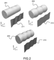
- FIG. 2 schematizes several examples of guided modes in a structure having the shape of a tube for a harmonic wave in time, of angular frequency ⁇ .
- the examples given are generalized to the transient regime by a Fourier transform with respect to time.
- the examples of the figure 2 correspond to guided modes of torsion (201), compression (202) and flexion (203) type.
- Or e 3 r denotes the unit vector of the guide axis r.
- the diffracted field is the field obtained after subtraction of the field incident, which is the field propagating in the absence of a fault.
- the sum of the diffracted field and the incident field is called the total field.
- the field diffracted by a defect in a waveguide can be expressed according to the different modes. More precisely, all fields can be expressed on a modal basis (base defined by the modes), the defect can be characterized by the diffraction of the different modes, represented in a diffraction matrix.
- the diffraction matrix S is the projection of the diffracted fields associated with the different incident modes onto the transverse functions associated with the different modes, and this following the directions of propagation in the guides.
- the diffraction matrix therefore presents four blocks in a simple guide, corresponding respectively to an incident field propagating in the direction of increasing, respectively decreasing axial coordinates, for a diffracted field propagating in the direction of increasing, respectively decreasing axial coordinates.
- the diffraction matrix S makes it possible to describe the diffraction by the defect of any incident field.
- N guides with N strictly greater than 2, by defining the N 2 blocks of the diffraction matrix, these blocks corresponding to the diffracted fields propagating in the N guides for the different incident fields propagating in these N guides.
- junction 104 In the case of a guide 101 connected to a junction 104 (as shown in figure 1 ), the diffraction of the junction and the defect are treated separately.
- This total field is called reference field and noted u not j , ref for the nth incident mode u not j of the guide j. It corresponds to the sum of the incident field and the diffracted field on junction 104.
- this defect also generates a diffracted field.
- the field diffracted by the defect corresponds to the diffraction by the defect of the reference field.
- Document [1] describes the application of a digital resolution method called LSM (Linear Sampling Method) to the imaging of elastic waveguides.
- LSM Linear Sampling Method
- This method is based on the diffraction matrix S which corresponds to the projection, on the transverse functions of the modes of the different guides, of the different diffracted fields associated with the reference fields, in other words the diffracted fields associated with the single defect to be imaged.
- the LSM method is applicable both when all the blocks of the matrix are accessible and when only certain blocks are accessible, namely when only certain reference fields have been emitted and certain diffracted fields have been measured.
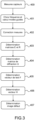
- FIG. 3 describes, on a flowchart, the steps of implementing a method of imaging a structure of the type described in figure 1 .
- the invention is implemented by means of elastic ultrasonic wave sensors 110,111.
- the sensors are chosen from piezoelectric transducers, electromagnetic acoustic transducers (for example of the EMAT or magnetostrictive patch type) or Bragg grating sensors on optical fiber.
- the sensors 110,111 can be positioned on the surface of the structure or integrated into it in selected locations sufficiently far from the defects and the junction.
- Each sensor 110,111 is connected to a signal acquisition chain and all of the sensors are connected to a processing unit 120 which is configured to execute the imaging method according to one of the embodiments of the invention.
- the processing unit 120 can be produced in software and/or hardware form from a processor and a memory.
- the processor can be a generic processor, a specific processor, an application-specific integrated circuit (also known as ASIC for “Application-Specific Integrated Circuit”) or an array of in situ programmable gates (also known as the English name of FPGA for “Field-Programmable Gate Array”).
- the results provided by the processing unit can be displayed on a computer screen or directly on an interface forming part of the device.
- the sensors can be arranged on either side or only on one side of the zone to be imaged. Their positions can be determined randomly or in a regular pattern.
- Each sensor can combine both the function of transmitter and receiver or only one of the two functions.
- the method which is the subject of the invention begins with a first step 400 of acquiring measurements of ultrasonic signals by the different sensors acting as receiving sensors.
- Different acquisition methods can be considered, for example a sequential acquisition during which each transmitter successively generates an elastic wave in the structure and a measurement of the propagated signal is carried out by all the receivers for each elastic wave emitted.
- a temporal Fourier transform is then applied to the measurements, and the different guided modes are determined from the reference structure by a digital method, for example a “SAFE” type method.
- the method which is the subject of the invention is applicable for one or more frequencies of the bandwidth. We therefore select in step 401 a frequency of interest.
- correction signals are subtracted from the measurements, corresponding to the ultrasonic signals acquired in the same configuration on the structure 100 but in the absence of a defect.
- These signals can be obtained for example by a measurement on the healthy, defect-free structure 100, or by a finite element calculation or by simulation. In the latter case, the guided modes determined in step 401 are used to obtain these signals.
- the measurements are grouped into a matrix whose rows correspond to the emissions and the columns correspond to the receivers. Each measurement consists of a sequence of samples obtained for a predetermined acquisition duration. In other words, the measurements are characterized by three dimensions: the transmitter index, the receiver index and the time sample index.
- several transmitters can transmit signals simultaneously.
- the sequence of measurements can be carried out in various ways by varying the sequencing and the number of transmissions, receptions and also the acquisition duration.
- emissions can be simultaneous or successive by several sensors.
- the modal coefficients being the projections of the fields on the transverse functions of the modes in the section of the guide, it is necessary to have access to the latter to calculate them.
- a solution proposed in reference [2] consists of establishing a link between measurements acquired on the surface of the waveguide and the diffraction matrix.
- the principle is as follows: consider a set of sources and receivers positioned on the surface of the waveguide.
- the numbers, positions and types (piezoelectric, EMAT, etc.) of sensors acting as sources may be identical or different from those acting as receivers.
- the sources and receivers are assumed to be located away from the fault along the axis. Under these conditions, it is possible to decompose the fields measured by the receivers for each source as combinations of the guided modes, and to retain in this combination only the contributions of the propagative modes, the other contributions having, by hypothesis, been attenuated. before reaching the sensors.
- the transmission matrices ⁇ and reception depend only on the guided modes, and the sources and receivers. Note that the number of sources and receivers can be greater than the number of propagating modes, the matrices R and ⁇ are rectangular in general, the system must then be resolved in the least squares sense.
- the transmission matrices ⁇ and reception matrices are therefore determined as follows.
- reception and transmission functions are defined by the characteristics of the sensors (their type, transmission power, etc.).
- matrices and ⁇ are constructed by blocks, the extra-diagonal blocks being zero. Indeed, we see in the previous expressions that, for the matrix R, each row corresponds to a sensor while each column corresponds to a guided mode. This is always the case in the case of sensors positioned on several guides, but the guided modes correspond to the different guides. Thus, the coefficient corresponding to the integral for a sensor on a first guide for a mode associated with another guide is zero. This analysis is also valid for the matrix ⁇ by reversing the rows and columns.
- the emission matrix ⁇ has the dimensions of the product of the sum of the number of transmitters on each guide by the sum of the number of propagative guided modes in each guide.
- the reception matrix R has the dimensions of the product of the sum of the number of receivers on each guide by the sum of the number of propagative guided modes in each guide.
- U is the diffraction matrix determined in step 404 which only contains the contributions of the fields diffracted by the defect to be imaged.
- H(x) is a vector of modal components to be determined at any point x of a sampling grid defining the area to be imaged.
- H(x) is linked to the image obtained by the method which is the subject of the invention. This is a vector that we seek to determine in order to image the structure.
- F(x) is a vector which depends on the characteristics of the structure to be imaged without defects, that is to say the healthy structure. This vector can be calculated by simulating the propagation of the guided modes in the defect-free structure. In other words, F(x) corresponds to the theoretical response of the defect-free structure.
- This vector are the projections of the Green tensor of the domain (which corresponds to the defect-free structure), on the transverse functions of the guided modes.
- the wave fields are vector and the Green function corresponds to a tensor of order 2.
- the Green tensor is written as a function of the reference fields.
- reference field u not j ref corresponding to the response of the structure in the absence of a fault, to the incident guided mode n of the guide j.
- the reference field corresponds to the total field diffracted by the defect-free structure as explained in the preamble.
- each guide r (excluding junction) are defined as the product of a function of the local transverse variable x s r and an oscillating and/or exponentially decreasing function of the local axial variable x 3 r .
- ⁇ m r is the wave number of the mode m of the guide r
- R r is the coordinate along the axis of the guide r of the section ⁇ r and u m r , ref the reference field associated with the mode m of the guide r .
- the vector F(x) can be determined by means of relation (7) having previously calculated the reference fields (fields diffracted by the structure in the absence of defects) by solving the system (5).
- the final vector H is calculated for each position x of the sampling grid, for an angular frequency ⁇ and for a polarization p.
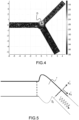
- FIG 4 illustrates an imaging result obtained by the method which is the subject of the invention for a structure of the type of figure 1 having a defect D.
- a difficulty inherent to the modal LSM method generalized to guide junctions is the need to numerically calculate the reference fields for each point of the area to be imaged in order to calculate the vector F(x). Indeed, as explained previously, this calculation requires numerically solving the system of equations (5) in each guide r connected to the junction.
- one solution is to couple the resolution of the numerical problem with an analytical propagation of the reference fields. Indeed, when calculating the reference fields using equations (5) the calculation domain coincides with the sampling area for the LSM method, delimited by the sections ⁇ l .
- the solution proposed here consists of defining the sections ⁇ l close to the junction for the finite element calculation, then analytically propagating the reference field obtained for the guides of constant section.
- u m r ref (associated with the defect-free structure for the incident mode m in the guide r) and let u scat be the field diffracted by the defect-free junction.
- u scat u m r , ref ⁇ u m r in the guide r defined by the structure as shown in Figure 6.
- u scat u m r , ref u scat in the rest of the guide (excluding junction).
- u m r ref is the solution to (5).
- the reference field u m r , ref was calculated in the finite element domain.
- HAS not L X not L , Y L u scat ⁇ L .
- the finite element calculation carried out almost directly provides the variable y l ( u scat ): in fact, the finite element calculation provides Y L u m r , ref thanks to the use of the operators T l , and the variable Y m r is obtained in the calculation of the modes by digital resolution, for example by a SAFE method.
- the values of the reference fields at the other points of the sampling grid are therefore deduced by an analytical propagation calculation. of the incident field and the field diffracted by the disturbance, inexpensive in terms of calculation time and memory.
- the vector F(x) is then calculated and steps 405,406,407 of the method described previously are applied.
Landscapes
- Physics & Mathematics (AREA)
- General Physics & Mathematics (AREA)
- Pathology (AREA)
- Chemical & Material Sciences (AREA)
- Analytical Chemistry (AREA)
- Biochemistry (AREA)
- General Health & Medical Sciences (AREA)
- Health & Medical Sciences (AREA)
- Immunology (AREA)
- Life Sciences & Earth Sciences (AREA)
- Acoustics & Sound (AREA)
- Engineering & Computer Science (AREA)
- Signal Processing (AREA)
- Algebra (AREA)
- Mathematical Physics (AREA)
- Pure & Applied Mathematics (AREA)
- Mathematical Optimization (AREA)
- Mathematical Analysis (AREA)
- Spectroscopy & Molecular Physics (AREA)
- Investigating Or Analyzing Materials By The Use Of Ultrasonic Waves (AREA)
- Mechanical Light Control Or Optical Switches (AREA)
Claims (13)
- Verfahren zum Abbilden einer Struktur (100) bestehend aus mindestens einem Wellenleiter (101, 102, 103), der mit einem Knotenpunkt (104) verbunden ist, wobei die Struktur geführte Ausbreitungsmoden elastischer Wellen unterstützt, wobei die Struktur (100) mindestens einen Defekt aufweist, wobei das Verfahren die folgenden Schritte umfasst:- Erfassen (400), für mindestens eine Betriebsfrequenz, mehrerer Messwerte von sich in der Struktur (100) ausbreitenden Signalen mittels einer Vielzahl von Paaren von nicht kolokalisierten Sensoren (110, 111) für elastische Wellen, wobei die Messwerte in einer Messmatrixorganisiert werden, deren Dimensionen gleich der Anzahl von Sendersensoren durch die Anzahl von Empfängersensoren sind,
 - Bestimmen (401) einer Vielzahl von durch die Struktur geführten Ausbreitungsmoden,- Korrigieren (402) der Messwerte auf der Basis von Ultraschallsignalen, die für dieselbe Struktur (100) in Abwesenheit eines Defekts gemessen oder simuliert wurden,- Umwandeln (403, 404) der Messmatrixin eine Beugungsmatrix von Wellenfeldern U,- Bestimmen, an jedem Punkt eines Abtastrasters (405), eines für die defektfreie Struktur (100) charakteristischen Testvektors F, dessen Komponenten die Projektionen eines Green-Tensors des defektfreien Bereichs auf die Querfunktionen der geführten Ausbreitungsmoden sind,- Anwenden (406) einer numerischen Inversionsmethode zum Bestimmen eines Vektors H von Modalkomponenten, so dass an jedem Punkt eines Abtastrasters U.H=F,- Bestimmen (407) eines Bildes der Struktur auf der Basis des Vektors H.
- Bildgebungsverfahren nach Anspruch 1, wobei die Beugungsmatrix U mittels der Beziehung

- Bildgebungsverfahren nach einem der vorhergehenden Ansprüche, wobei der Testvektor F bestimmt wird (405) durch:- Berechnen von Referenzwellenfeldern, die Summen von einfallenden Wellenfeldern und durch den Knotenpunkt (104) gebeugten Wellenfeldern in Abwesenheit eines Defekts in der Struktur (100) entsprechen,- Bestimmen des Testvektors F auf der Basis der berechneten Referenzwellenfelder.
- Bildgebungsverfahren nach Anspruch 3, wobei die Referenzwellenfelder mithilfe einer numerischen Finite-Elemente-Auflösung berechnet werden.
- Bildgebungsverfahren nach Anspruch 4, wobei die Referenzwellenfelder mittels einer numerischen Finite-Elemente-Auflösung in einer durch den Knotenpunkt (104) definierten Zone berechnet werden und sich dann analytisch in jedem Wellenleiter (101, 102, 103) ausbreiten.
- Bildgebungsverfahren nach Anspruch 5, wobei die Referenzwellenfelder in jedem Wellenleiter auf der Basis der Referenzwellenfelder in dem Knotenpunkt mittels folgender Schritte berechnet werden:- Bestimmen der am Knotenpunkt gebeugten Wellenfelder auf der Basis der Referenzwellenfelder,- Ausbreiten der durch den Knotenpunkt gebeugten Wellenfelder in jedem Wellenleiter durch Berechnen der Summe der geführten Ausbreitungsmoden, die mit den Modalkoeffizienten der gebeugten Wellenfelder gewichtet sind,- Bestimmen der Referenzwellenfelder in jedem Wellenleiter als die Summe der ausgebreiteten gebeugten Wellenfelder und der geführten Ausbreitungsmoden.
- Bildgebungsverfahren nach einem der vorhergehenden Ansprüche, wobei das Bild der Struktur auf der Basis des Kehrwerts der Norm des H-Vektors an jedem beliebigen Punkt der abzubildenden Struktur bestimmt wird.
- Bildgebungsverfahren nach einem der Ansprüche 1 bis 6, wobei die Schritte des Verfahrens für mehrere Betriebsfrequenzen ausgeführt werden.
- Bildgebungsverfahren nach Anspruch 8, wobei die Abbildung der Struktur auf der Basis einer Summe der quadrierten Normen der für verschiedene Betriebsfrequenzen berechneten H-Vektoren an jedem beliebigen Punkt der abzubildenden Struktur bestimmt wird.
- Bildgebungsverfahren nach einem der vorhergehenden Ansprüche, wobei die Sensoren für elastische Wellen auf der Oberfläche der Struktur positioniert oder in die Struktur integriert sind.
- Bildgebungsvorrichtung, die eine Anordnung von zum Positionieren auf einer abzubildenden Struktur bestimmten Sensoren für elastische Wellen und eine Verarbeitungseinheit umfasst, die zum Empfangen der von den Sensoren erfassten Signale ausgelegt und zum Ausführen der Schritte des Bildgebungsverfahrens nach einem der vorhergehenden Ansprüche konfiguriert ist.
- Bildgebungsvorrichtung nach Anspruch 11, wobei die Sensoren für elastische Wellen aus piezoelektrischen Wandlern, elektromagnetischen akustischen Wandlern und faseroptischen Bragg-Gitter-Sensoren ausgewählt sind.
- Bildgebungsvorrichtung nach Anspruch 11 oder 12, wobei die Sensoren für elastische Wellen auf der Oberfläche der Struktur positioniert oder in die Struktur integriert sind.
Applications Claiming Priority (1)
| Application Number | Priority Date | Filing Date | Title |
|---|---|---|---|
| FR2012832A FR3117215B1 (fr) | 2020-12-08 | 2020-12-08 | Imagerie de guides d’ondes élastiques interconnectés par une jonction |
Publications (3)
| Publication Number | Publication Date |
|---|---|
| EP4012402A1 EP4012402A1 (de) | 2022-06-15 |
| EP4012402B1 true EP4012402B1 (de) | 2023-10-04 |
| EP4012402C0 EP4012402C0 (de) | 2023-10-04 |
Family
ID=74347369
Family Applications (1)
| Application Number | Title | Priority Date | Filing Date |
|---|---|---|---|
| EP21212170.1A Active EP4012402B1 (de) | 2020-12-08 | 2021-12-03 | Bildgebung von elastischen wellenleitern, die durch einen übergang miteinander verbunden sind |
Country Status (4)
| Country | Link |
|---|---|
| US (1) | US12216088B2 (de) |
| EP (1) | EP4012402B1 (de) |
| ES (1) | ES2967471T3 (de) |
| FR (1) | FR3117215B1 (de) |
Families Citing this family (1)
| Publication number | Priority date | Publication date | Assignee | Title |
|---|---|---|---|---|
| CN114778691B (zh) * | 2022-06-16 | 2022-09-06 | 南京航空航天大学 | 一种变阵列形式的超声导波定量化成像方法 |
Family Cites Families (1)
| Publication number | Priority date | Publication date | Assignee | Title |
|---|---|---|---|---|
| ITMI20150556A1 (it) * | 2015-04-16 | 2016-10-16 | Univ Bologna Alma Mater Studiorum | Dispositivo, sistema e metodo per la diagnostica strutturale in tempo reale con onde elastiche guidate |
-
2020
- 2020-12-08 FR FR2012832A patent/FR3117215B1/fr active Active
-
2021
- 2021-12-03 EP EP21212170.1A patent/EP4012402B1/de active Active
- 2021-12-03 ES ES21212170T patent/ES2967471T3/es active Active
- 2021-12-06 US US17/543,270 patent/US12216088B2/en active Active
Also Published As
| Publication number | Publication date |
|---|---|
| FR3117215B1 (fr) | 2022-12-09 |
| EP4012402A1 (de) | 2022-06-15 |
| EP4012402C0 (de) | 2023-10-04 |
| US12216088B2 (en) | 2025-02-04 |
| ES2967471T3 (es) | 2024-04-30 |
| US20220178883A1 (en) | 2022-06-09 |
| FR3117215A1 (fr) | 2022-06-10 |
Similar Documents
| Publication | Publication Date | Title |
|---|---|---|
| EP3707503B1 (de) | Überwachung der strukturellen gesundheit für eine industriestruktur | |
| Rossetto et al. | Locating a weak change using diffuse waves: Theoretical approach and inversion procedure | |
| EP3824280B1 (de) | Verfahren und systeme zur nichtinvasiven charakterisierung eines heterogenen mediums mittels ultraschall | |
| Ilonidis et al. | Detection of emerging sunspot regions in the solar interior | |
| Chehami et al. | Detection and localization of a defect in a reverberant plate using acoustic field correlation | |
| EP2294452B1 (de) | Messverfahren und -Vorrichtung unter Verwendung von Wellenausbreitung | |
| EP3077795B1 (de) | Prüfung einer industriestruktur | |
| CA1322395C (fr) | Dispositif d'emission et de reception d'un rayonnement micro-onde, pour imagerie d'objets enfouis | |
| EP2440140B1 (de) | Methode und ultraschallgerät zur characterisierung eines mediums | |
| EP2972072B1 (de) | Spannungsmessvorrichtung | |
| Larose et al. | Fluctuations of correlations and Green’s function reconstruction: role of scattering | |
| US20180106765A1 (en) | Ultrasonic inspection technique to assess bond quality in composite structures | |
| EP0124442B1 (de) | Verfahren und Vorrichtung zur akustischen Holographie bei Verwendung eines räumlich begrenzten Ultraschallstrahlenbündels | |
| EP1580524B1 (de) | Verfahren und Vorrichtung zur Charakterisierung von Strukturschäden mittels Moiré- Schatten | |
| EP3084416B1 (de) | Verfahren zur verarbeitung von signalen aus einer ultraschallsondenerfassung, entsprechendes computerprogramm und ultraschallsondenvorrichtung | |
| EP3899523B1 (de) | Verfahren zur ultraschallbildgebung mittels zweidimensionaler fourier-transformation, zugehörige ultraschallsondenvorrichtung und computerprogramm | |
| FR3099580A1 (fr) | Procédé et système de caractérisation ultrasonore non invasive d’un milieu hétérogène | |
| EP4012402A1 (de) | Bildgebung von elastischen wellenleitern, die durch einen übergang miteinander verbunden sind | |
| Narumanchi et al. | Laser ultrasonic imaging of subsurface defects with the linear sampling method | |
| WO2024074252A1 (fr) | Procede d'imagerie ultrasonore par transformee de fourier multidimensionnelle a l'aide de deux transducteurs multielements distincts | |
| EP0197582B1 (de) | Verfahren und Vorrichtung zur Untersuchung von Medien mittels Ultraschall-Echographie | |
| EP3044580B1 (de) | Verfahren zur zerstörungsfreien ultraschallprüfung eines bauteils mittels echoanalyse | |
| EP2929343B1 (de) | Vorrichtung und verfahren zur ultraschalllbildgebeung mit filterung von artefakten aufgrund von interferenzen zwischen rekonstruktionsmoden | |
| EP4217727B1 (de) | Kalibrierungsverfahren für an zylinderartige strukturen angepasste geführte elastische wellentomografie | |
| EP4563996A1 (de) | Verfahren zur automatischen kalibrierung eines ultraschallwandlers |
Legal Events
| Date | Code | Title | Description |
|---|---|---|---|
| PUAI | Public reference made under article 153(3) epc to a published international application that has entered the european phase |
Free format text: ORIGINAL CODE: 0009012 |
|
| STAA | Information on the status of an ep patent application or granted ep patent |
Free format text: STATUS: REQUEST FOR EXAMINATION WAS MADE |
|
| 17P | Request for examination filed |
Effective date: 20211203 |
|
| AK | Designated contracting states |
Kind code of ref document: A1 Designated state(s): AL AT BE BG CH CY CZ DE DK EE ES FI FR GB GR HR HU IE IS IT LI LT LU LV MC MK MT NL NO PL PT RO RS SE SI SK SM TR |
|
| RIC1 | Information provided on ipc code assigned before grant |
Ipc: G01N 29/06 20060101ALI20230403BHEP Ipc: G01N 29/04 20060101ALI20230403BHEP Ipc: G01N 29/44 20060101AFI20230403BHEP |
|
| GRAP | Despatch of communication of intention to grant a patent |
Free format text: ORIGINAL CODE: EPIDOSNIGR1 |
|
| STAA | Information on the status of an ep patent application or granted ep patent |
Free format text: STATUS: GRANT OF PATENT IS INTENDED |
|
| INTG | Intention to grant announced |
Effective date: 20230516 |
|
| GRAS | Grant fee paid |
Free format text: ORIGINAL CODE: EPIDOSNIGR3 |
|
| GRAA | (expected) grant |
Free format text: ORIGINAL CODE: 0009210 |
|
| STAA | Information on the status of an ep patent application or granted ep patent |
Free format text: STATUS: THE PATENT HAS BEEN GRANTED |
|
| AK | Designated contracting states |
Kind code of ref document: B1 Designated state(s): AL AT BE BG CH CY CZ DE DK EE ES FI FR GB GR HR HU IE IS IT LI LT LU LV MC MK MT NL NO PL PT RO RS SE SI SK SM TR |
|
| REG | Reference to a national code |
Ref country code: GB Ref legal event code: FG4D Free format text: NOT ENGLISH |
|
| REG | Reference to a national code |
Ref country code: CH Ref legal event code: EP |
|
| REG | Reference to a national code |
Ref country code: IE Ref legal event code: FG4D Free format text: LANGUAGE OF EP DOCUMENT: FRENCH |
|
| REG | Reference to a national code |
Ref country code: DE Ref legal event code: R096 Ref document number: 602021005624 Country of ref document: DE |
|
| U01 | Request for unitary effect filed |
Effective date: 20231017 |
|
| U07 | Unitary effect registered |
Designated state(s): AT BE BG DE DK EE FI FR IT LT LU LV MT NL PT SE SI Effective date: 20231025 |
|
| REG | Reference to a national code |
Ref country code: NO Ref legal event code: T2 Effective date: 20231004 |
|
| U20 | Renewal fee for the european patent with unitary effect paid |
Year of fee payment: 3 Effective date: 20240119 |
|
| PG25 | Lapsed in a contracting state [announced via postgrant information from national office to epo] |
Ref country code: GR Free format text: LAPSE BECAUSE OF FAILURE TO SUBMIT A TRANSLATION OF THE DESCRIPTION OR TO PAY THE FEE WITHIN THE PRESCRIBED TIME-LIMIT Effective date: 20240105 |
|
| PG25 | Lapsed in a contracting state [announced via postgrant information from national office to epo] |
Ref country code: IS Free format text: LAPSE BECAUSE OF FAILURE TO SUBMIT A TRANSLATION OF THE DESCRIPTION OR TO PAY THE FEE WITHIN THE PRESCRIBED TIME-LIMIT Effective date: 20240204 |
|
| PG25 | Lapsed in a contracting state [announced via postgrant information from national office to epo] |
Ref country code: IS Free format text: LAPSE BECAUSE OF FAILURE TO SUBMIT A TRANSLATION OF THE DESCRIPTION OR TO PAY THE FEE WITHIN THE PRESCRIBED TIME-LIMIT Effective date: 20240204 Ref country code: GR Free format text: LAPSE BECAUSE OF FAILURE TO SUBMIT A TRANSLATION OF THE DESCRIPTION OR TO PAY THE FEE WITHIN THE PRESCRIBED TIME-LIMIT Effective date: 20240105 |
|
| REG | Reference to a national code |
Ref country code: ES Ref legal event code: FG2A Ref document number: 2967471 Country of ref document: ES Kind code of ref document: T3 Effective date: 20240430 |
|
| PG25 | Lapsed in a contracting state [announced via postgrant information from national office to epo] |
Ref country code: RS Free format text: LAPSE BECAUSE OF FAILURE TO SUBMIT A TRANSLATION OF THE DESCRIPTION OR TO PAY THE FEE WITHIN THE PRESCRIBED TIME-LIMIT Effective date: 20231004 Ref country code: PL Free format text: LAPSE BECAUSE OF FAILURE TO SUBMIT A TRANSLATION OF THE DESCRIPTION OR TO PAY THE FEE WITHIN THE PRESCRIBED TIME-LIMIT Effective date: 20231004 Ref country code: HR Free format text: LAPSE BECAUSE OF FAILURE TO SUBMIT A TRANSLATION OF THE DESCRIPTION OR TO PAY THE FEE WITHIN THE PRESCRIBED TIME-LIMIT Effective date: 20231004 |
|
| REG | Reference to a national code |
Ref country code: DE Ref legal event code: R097 Ref document number: 602021005624 Country of ref document: DE |
|
| PG25 | Lapsed in a contracting state [announced via postgrant information from national office to epo] |
Ref country code: CZ Free format text: LAPSE BECAUSE OF FAILURE TO SUBMIT A TRANSLATION OF THE DESCRIPTION OR TO PAY THE FEE WITHIN THE PRESCRIBED TIME-LIMIT Effective date: 20231004 |
|
| PG25 | Lapsed in a contracting state [announced via postgrant information from national office to epo] |
Ref country code: SK Free format text: LAPSE BECAUSE OF FAILURE TO SUBMIT A TRANSLATION OF THE DESCRIPTION OR TO PAY THE FEE WITHIN THE PRESCRIBED TIME-LIMIT Effective date: 20231004 |
|
| PG25 | Lapsed in a contracting state [announced via postgrant information from national office to epo] |
Ref country code: SM Free format text: LAPSE BECAUSE OF FAILURE TO SUBMIT A TRANSLATION OF THE DESCRIPTION OR TO PAY THE FEE WITHIN THE PRESCRIBED TIME-LIMIT Effective date: 20231004 Ref country code: SK Free format text: LAPSE BECAUSE OF FAILURE TO SUBMIT A TRANSLATION OF THE DESCRIPTION OR TO PAY THE FEE WITHIN THE PRESCRIBED TIME-LIMIT Effective date: 20231004 Ref country code: RO Free format text: LAPSE BECAUSE OF FAILURE TO SUBMIT A TRANSLATION OF THE DESCRIPTION OR TO PAY THE FEE WITHIN THE PRESCRIBED TIME-LIMIT Effective date: 20231004 Ref country code: CZ Free format text: LAPSE BECAUSE OF FAILURE TO SUBMIT A TRANSLATION OF THE DESCRIPTION OR TO PAY THE FEE WITHIN THE PRESCRIBED TIME-LIMIT Effective date: 20231004 |
|
| PLBE | No opposition filed within time limit |
Free format text: ORIGINAL CODE: 0009261 |
|
| STAA | Information on the status of an ep patent application or granted ep patent |
Free format text: STATUS: NO OPPOSITION FILED WITHIN TIME LIMIT |
|
| PG25 | Lapsed in a contracting state [announced via postgrant information from national office to epo] |
Ref country code: MC Free format text: LAPSE BECAUSE OF FAILURE TO SUBMIT A TRANSLATION OF THE DESCRIPTION OR TO PAY THE FEE WITHIN THE PRESCRIBED TIME-LIMIT Effective date: 20231004 |
|
| PG25 | Lapsed in a contracting state [announced via postgrant information from national office to epo] |
Ref country code: MC Free format text: LAPSE BECAUSE OF FAILURE TO SUBMIT A TRANSLATION OF THE DESCRIPTION OR TO PAY THE FEE WITHIN THE PRESCRIBED TIME-LIMIT Effective date: 20231004 |
|
| 26N | No opposition filed |
Effective date: 20240705 |
|
| REG | Reference to a national code |
Ref country code: IE Ref legal event code: MM4A |
|
| PG25 | Lapsed in a contracting state [announced via postgrant information from national office to epo] |
Ref country code: IE Free format text: LAPSE BECAUSE OF NON-PAYMENT OF DUE FEES Effective date: 20231203 |
|
| U1H | Name or address of the proprietor changed after the registration of the unitary effect |
Owner name: ECOLE NATIONALE SUPERIEURE DE TECHNIQUES AVANCEES; FR Owner name: COMMISSARIAT A L'ENERGIE ATOMIQUE ET AUX ENERGIESALTERNATIVES; FR |
|
| PG25 | Lapsed in a contracting state [announced via postgrant information from national office to epo] |
Ref country code: IE Free format text: LAPSE BECAUSE OF NON-PAYMENT OF DUE FEES Effective date: 20231203 |
|
| PGFP | Annual fee paid to national office [announced via postgrant information from national office to epo] |
Ref country code: NO Payment date: 20241216 Year of fee payment: 4 |
|
| U20 | Renewal fee for the european patent with unitary effect paid |
Year of fee payment: 4 Effective date: 20241218 |
|
| PGFP | Annual fee paid to national office [announced via postgrant information from national office to epo] |
Ref country code: ES Payment date: 20250117 Year of fee payment: 4 |
|
| PG25 | Lapsed in a contracting state [announced via postgrant information from national office to epo] |
Ref country code: CY Free format text: LAPSE BECAUSE OF FAILURE TO SUBMIT A TRANSLATION OF THE DESCRIPTION OR TO PAY THE FEE WITHIN THE PRESCRIBED TIME-LIMIT; INVALID AB INITIO Effective date: 20211203 |
|
| REG | Reference to a national code |
Ref country code: CH Ref legal event code: PL |
|
| PG25 | Lapsed in a contracting state [announced via postgrant information from national office to epo] |
Ref country code: CH Free format text: LAPSE BECAUSE OF NON-PAYMENT OF DUE FEES Effective date: 20241231 |
|
| PG25 | Lapsed in a contracting state [announced via postgrant information from national office to epo] |
Ref country code: TR Free format text: LAPSE BECAUSE OF FAILURE TO SUBMIT A TRANSLATION OF THE DESCRIPTION OR TO PAY THE FEE WITHIN THE PRESCRIBED TIME-LIMIT Effective date: 20231004 |
|
| PG25 | Lapsed in a contracting state [announced via postgrant information from national office to epo] |
Ref country code: HU Free format text: LAPSE BECAUSE OF FAILURE TO SUBMIT A TRANSLATION OF THE DESCRIPTION OR TO PAY THE FEE WITHIN THE PRESCRIBED TIME-LIMIT; INVALID AB INITIO Effective date: 20211203 |
|
| PG25 | Lapsed in a contracting state [announced via postgrant information from national office to epo] |
Ref country code: CH Free format text: THE PATENT HAS BEEN ANNULLED BY A DECISION OF A NATIONAL AUTHORITY Effective date: 20241231 |
|
| U90 | Renewal fees not paid: noting of loss of rights |
Free format text: RENEWAL FEE NOT PAID FOR YEAR 05 Effective date: 20260709 |