EP4012382A1 - Hydrogen permeation test device - Google Patents
Hydrogen permeation test device Download PDFInfo
- Publication number
- EP4012382A1 EP4012382A1 EP20863388.3A EP20863388A EP4012382A1 EP 4012382 A1 EP4012382 A1 EP 4012382A1 EP 20863388 A EP20863388 A EP 20863388A EP 4012382 A1 EP4012382 A1 EP 4012382A1
- Authority
- EP
- European Patent Office
- Prior art keywords
- hydrogen
- testing device
- permeability testing
- amount
- sodium silicate
- Prior art date
- Legal status (The legal status is an assumption and is not a legal conclusion. Google has not performed a legal analysis and makes no representation as to the accuracy of the status listed.)
- Granted
Links
Images


Classifications
-
- G—PHYSICS
- G01—MEASURING; TESTING
- G01N—INVESTIGATING OR ANALYSING MATERIALS BY DETERMINING THEIR CHEMICAL OR PHYSICAL PROPERTIES
- G01N27/00—Investigating or analysing materials by the use of electric, electrochemical, or magnetic means
- G01N27/02—Investigating or analysing materials by the use of electric, electrochemical, or magnetic means by investigating impedance
- G01N27/04—Investigating or analysing materials by the use of electric, electrochemical, or magnetic means by investigating impedance by investigating resistance
- G01N27/041—Investigating or analysing materials by the use of electric, electrochemical, or magnetic means by investigating impedance by investigating resistance of a solid body
-
- G—PHYSICS
- G01—MEASURING; TESTING
- G01N—INVESTIGATING OR ANALYSING MATERIALS BY DETERMINING THEIR CHEMICAL OR PHYSICAL PROPERTIES
- G01N27/00—Investigating or analysing materials by the use of electric, electrochemical, or magnetic means
- G01N27/26—Investigating or analysing materials by the use of electric, electrochemical, or magnetic means by investigating electrochemical variables; by using electrolysis or electrophoresis
-
- G—PHYSICS
- G01—MEASURING; TESTING
- G01N—INVESTIGATING OR ANALYSING MATERIALS BY DETERMINING THEIR CHEMICAL OR PHYSICAL PROPERTIES
- G01N27/00—Investigating or analysing materials by the use of electric, electrochemical, or magnetic means
- G01N27/26—Investigating or analysing materials by the use of electric, electrochemical, or magnetic means by investigating electrochemical variables; by using electrolysis or electrophoresis
- G01N27/403—Cells and electrode assemblies
- G01N27/413—Concentration cells using liquid electrolytes measuring currents or voltages in voltaic cells
-
- G—PHYSICS
- G01—MEASURING; TESTING
- G01N—INVESTIGATING OR ANALYSING MATERIALS BY DETERMINING THEIR CHEMICAL OR PHYSICAL PROPERTIES
- G01N13/00—Investigating surface or boundary effects, e.g. wetting power; Investigating diffusion effects; Analysing materials by determining surface, boundary, or diffusion effects
- G01N13/04—Investigating osmotic effects
-
- G—PHYSICS
- G01—MEASURING; TESTING
- G01N—INVESTIGATING OR ANALYSING MATERIALS BY DETERMINING THEIR CHEMICAL OR PHYSICAL PROPERTIES
- G01N17/00—Investigating resistance of materials to the weather, to corrosion, or to light
-
- G—PHYSICS
- G01—MEASURING; TESTING
- G01N—INVESTIGATING OR ANALYSING MATERIALS BY DETERMINING THEIR CHEMICAL OR PHYSICAL PROPERTIES
- G01N17/00—Investigating resistance of materials to the weather, to corrosion, or to light
- G01N17/006—Investigating resistance of materials to the weather, to corrosion, or to light of metals
-
- G—PHYSICS
- G01—MEASURING; TESTING
- G01N—INVESTIGATING OR ANALYSING MATERIALS BY DETERMINING THEIR CHEMICAL OR PHYSICAL PROPERTIES
- G01N27/00—Investigating or analysing materials by the use of electric, electrochemical, or magnetic means
- G01N27/26—Investigating or analysing materials by the use of electric, electrochemical, or magnetic means by investigating electrochemical variables; by using electrolysis or electrophoresis
- G01N27/28—Electrolytic cell components
-
- G—PHYSICS
- G01—MEASURING; TESTING
- G01N—INVESTIGATING OR ANALYSING MATERIALS BY DETERMINING THEIR CHEMICAL OR PHYSICAL PROPERTIES
- G01N27/00—Investigating or analysing materials by the use of electric, electrochemical, or magnetic means
- G01N27/26—Investigating or analysing materials by the use of electric, electrochemical, or magnetic means by investigating electrochemical variables; by using electrolysis or electrophoresis
- G01N27/416—Systems
-
- G—PHYSICS
- G01—MEASURING; TESTING
- G01N—INVESTIGATING OR ANALYSING MATERIALS BY DETERMINING THEIR CHEMICAL OR PHYSICAL PROPERTIES
- G01N33/00—Investigating or analysing materials by specific methods not covered by groups G01N1/00 - G01N31/00
- G01N33/20—Metals
- G01N33/202—Constituents thereof
- G01N33/2022—Non-metallic constituents
- G01N33/2025—Gaseous constituents
Definitions
- the present disclosure relates to a hydrogen permeability testing device capable of evaluating the amount of hydrogen in a metal material even at low temperatures.
- the bolts for the automobile suspension system may be exposed not only to the atmosphere, wind and rain when the automobile runs, but also to a strongly corrosive environment with an antifreezing agent such as NaCl or CaCl 2 spread in the wintertime for road deicing.
- Non Patent Document 1 Various methods have been proposed aiming at measuring the amount of hydrogen in a metal material.
- thermal desorption spectroscopy such as described in Non Patent Document 1 has been proposed as a common technique.
- a metal material is heated, and desorbed hydrogen is detected with use of a mass spectrometer or gas chromatography, whereby the amount and mode of existence of hydrogen in the metal material are evaluated.
- the amount of entered hydrogen however, largely varies depending on changes of temperature, humidity, amount of adhered salt or the like, and it has been difficult to evaluate temporal changes in the amount of entered hydrogen by the method described in Non Patent Document 1.
- An electrochemical hydrogen permeation method such as described in Non Patent Document 2 has been proposed as a common technique for evaluating the temporal changes in the amount of entered hydrogen.
- hydrogen is allowed to enter a metal material, with the aid of electrochemical cathode polarization or a corrosion-related cathode reaction, through one face (that is, hydrogen entry face) of the metal material.
- the entered hydrogen is rapidly oxidized by anodically polarizing the metal face on the opposite side (that is, hydrogen detection face) at an electric potential at which an oxidation reaction represented by H ⁇ H + + e can proceed rapidly enough, and the oxidation current is detected to estimate the amount of hydrogen.
- Non Patent Document 3 describes a test method capable of evaluating hydrogen entry in an atmospheric corrosive environment by exposing of the hydrogen entry face to the atmosphere.
- the method described in Non-Patent Document 3 uses an aqueous solution that contains NaOH, as a solution for oxidizing hydrogen (that is, a hydrogen detection solution) on the hydrogen detection face.
- a solution for oxidizing hydrogen that is, a hydrogen detection solution
- the antifreezing agent needs to be spread in a wintertime, the NaOH-containing aqueous solution freezes at low temperatures in such a wintertime. Freezing of the aqueous solution causes volume expansion of the aqueous solution, and has occasionally damaged the testing device.
- Non Patent Document 4 discloses an electrochemical hydrogen permeation method with use of an organic compound added to a hydrogen detection solution to depress the freezing point.
- the method described in Non Patent Document 4 uses a 0.2 M KOH solution in alcohol, containing a small amount of water, as a hydrogen detection solution, thus enabling the hydrogen permeability test applicable to a wide temperature range of 230 K to 300 K (-43°C to 27°C).
- Patent Document 1 proposes an electrochemical hydrogen permeation method that uses an organic compound added to a hydrogen detection solution so as to prevent freezing of the hydrogen detection solution.
- Patent Document 1 discusses a method for depressing the freezing point of the electrolytic solution to -5°C or lower, and discloses a hydrogen permeation test with use of hydrogen detection solutions prepared by adding various ratios of dimethyl sulfoxide (DMSO) to a 0.1 N aqueous NaOH solution.
- DMSO dimethyl sulfoxide
- Patent Document 1 JP 5754566 B2
- Non Patent Document 4 uses alcohol in the hydrogen detection solution.
- the alcohol in this case is oxidized when anodic polarization is induced on the hydrogen detection face at an electric potential for oxidizing hydrogen, and this oxidation reaction occasionally increases a noise current called a residual current. If the residual current is large, fluctuation in the residual current (i.e. noise) would mask hydrogen permeation current that occurs in response to entry of a trace amount of hydrogen. That is, it has been difficult to detect a trace amount of hydrogen caused by corrosion with high sensitivity.
- Patent Document 1 enables detection of a trace amount of hydrogen caused by corrosion, etc. by using DMSO as an organic compound to reduce the residual current.
- the method described in Patent Document 1 has, however, been aimed at depressing the freezing point of the electrolytic solution (that is, a hydrogen detection solution) to - 5°C or below, and has not necessarily been sufficient for use at very low temperatures such as -15°C or below. That is, Example described in Patent Document 1 are guessed to be difficult to carry out the hydrogen permeation test at very low temperatures such as -15°C or below, since the freezing point of the electrolytic solution (that is, the hydrogen detection solution) is - 12°C at the lowest.
- Embodiments of the present invention have been made under such circumstances, and an object of which is to provide a hydrogen permeability testing device capable of estimating the amount of hydrogen in a metal material, over a wide temperature range from very low temperatures at the freezing point or below, up to room temperature.
- An aspect 1 of the present invention is directed to a hydrogen permeability testing device for measuring the amount of hydrogen entering a metal material by using an electrochemical hydrogen permeation method, wherein the hydrogen permeability testing device comprises:
- An aspect 2 of embodiments of the present invention is directed to the hydrogen permeability testing device according to the aspect 1, wherein a relationship between Baumé degree Bh of the aqueous sodium silicate solution and an operating temperatureT (°C) satisfies T ⁇ -0.5 ⁇ exp (0.09 ⁇ Bh).
- An aspect 3 of embodiments of the present invention is directed to the hydrogen permeability testing device according to the aspect 1 or 2, wherein a molar ratio of SiO 2 /Na 2 O in the aqueous sodium silicate solution is 3.5 or smaller.
- An aspect 4 of embodiments of the present invention relates to the hydrogen permeability testing device according to any one of the aspects 1 to 3, wherein a concentration of a sodium silicate solution in the aqueous sodium silicate solution is 10% by mass or higher.
- An aspect 5 of embodiments of the present invention is directed to the hydrogen permeability testing device according to any one of the aspects 1 to 4, wherein the metal plating is formed of any one of Ni, Pd and Au.
- An aspect 6 of embodiments of the present invention relates to a method for measuring the amount of hydrogen, wherein the method comprising:
- the amount of hydrogen in a metal material can be measured over a wide temperature range from very low temperatures at the freezing point or below, up to room temperature.
- the inventors have intensively studied a hydrogen permeability testing device capable of (1) causing a small residual current when anodically polarizing at an electric potential for oxidizing hydrogen on the hydrogen detection face, (2) causing no corrosion of the metal material concerned, and (3) causing no damage on the hydrogen permeability testing device even at very low temperatures at the freezing point or below (for example, -15°C or below).
- the inventors consequently found that the residual current can be reduced without corroding the metal material concerned, by using a concentrated aqueous sodium silicate solution (that is, soda silicate) as the hydrogen detection solution in a predetermined structure.
- the inventors also found that the amount of hydrogen can be measured without damaging the hydrogen permeability testing device, even at very low temperatures which are the freezing point or below.
- the concentrated aqueous sodium silicate solution is, however, highly viscous and difficult to handle, as compared with aqueous sodium hydroxide solution having been used conventionally as the hydrogen detection solution. Therefore, the concentrated aqueous sodium silicate solution has not been used conventionally for the hydrogen permeability testing device.
- FIG. 1 is a schematic drawing illustrating a hydrogen permeability testing device 1 according to the embodiments of the present invention.
- a hydrogen permeability testing device 1 according to the embodiments of the present invention has a metal specimen 2, electrolytic vessels 3a, 3b, potentiostats/galvanostats 7a, 7b, and a recorder 8. Note that the potentiostat/galvanostat 7b and the recorder 8 constitute the "measurement unit" specified in CLAIMS.
- the two electrolytic vessels 3a, 3b are arranged opposed to each other, while placing the metal specimen 2 in between.
- a hole (not illustrated) through which the metal specimen 2 is contacted with a later-described solution 6a or a hydrogen detection solution 6b is provided at a part where the metal specimen 2 is attached.
- the electrolytic vessel 3a contains the solution 6a for making hydrogen enter the metal specimen 2.
- the solution 6a may be a solution having been used in a conventional hydrogen permeability testing device, and is a 0.1 M NaOH solution as an example.
- a counter electrode 4a is immersed.
- the potentiostat/galvanostat 7a is connected to the metal specimen 2 and the counter electrode 4a.
- the electrolytic vessel 3b contains the hydrogen detection solution 6b.
- the hydrogen detection solution 6b will be detailed later.
- a counter electrode 4b and a reference electrode 5b are immersed.
- the potentiostat/galvanostat 7b is connected to the metal specimen 2, the counter electrode 4b, and the reference electrode 5b.
- the recorder 8 is connected to the potentiostat/galvanostat 7b.
- the hydrogen permeability testing device 1 measures the amount of hydrogen that enters the metal specimen 2, with use of an electrochemical hydrogen permeation method.
- the electrochemical hydrogen permeation method per se has been known conventionally as a method for measuring a hydrogen permeability coefficient in steel plate.
- a surface of the metal specimen 2 in the electrolytic vessel 3a on the left side (may be occasionally referred to as "cathode side", hereinafter) is cathodically polarized at a constant electric potential or a constant current to generate and charge hydrogen.
- the metal specimen 2 is anodically polarized at a constant electric potential. This oxidizes hydrogen having permeated through the metal specimen 2 into hydrogen ion to produce oxidation-induced current, and the amount of permeated hydrogen can be determined from the current value.
- a structure on the cathode side is not limited specially, and any one of conventional structures is applicable for it. Note that, in the embodiments of the present invention, the structure on the cathode side is omissible. That is, in the embodiments of the present invention, a structure as illustrated in Fig. 4 described later may be applied. Generation and charging of hydrogen in this case are enabled, for example, by making the cathode side of the metal specimen 2 corrode in the atmosphere, etc.. The metal specimen 2 and structures of the anode side will be explained below.
- the metal specimen 2 is a target to be measured for the amount of hydrogen.
- the metal specimen 2 may have any shape of plate, rod, bolt or the like.
- the metal specimen 2 illustrated in Fig. 1 has a plate shape.
- the thickness is preferably 0.1 mm to 10 mm.
- the metal specimen 2 illustrated in Fig. 1 has a hydrogen entry face 2a through which hydrogen enters, and a hydrogen detection face 2b on which the entered hydrogen is detected.
- the metal specimen 2 may have strain introduced to the surface thereof by mechanical working such as cutting or polishing during manufacture. Results of measurement of the amount of hydrogen, especially the diffusion coefficient of hydrogen, may vary with the introduced strain. Therefore, it is preferable to electrolytically polish so that a position at a depth of 10 ⁇ m or deeper below the metal surface of the hydrogen detection face 2b will expose.
- a metal plating is formed on the hydrogen detection face 2b. With the metal plating thus formed, a trace amount of hydrogen can be easily detected. Specifically, this reduces a passivation-maintaining current of the hydrogen detection face 2b, and makes the oxidation reaction represented by H ⁇ H + + e smoothly progress.
- the passivation-maintaining current is a sort of the residual current. Reduction of the passivation-maintaining current can reduce the residual current, and enables easy detection of a trace amount of hydrogen.
- Type of the metal plating is preferably selected from materials having a small passivation-maintaining current, a dense and poreless structure, such as Ni plating, Pd plating, or Au plating. Method for plating is preferably electroplating, electroless plating, or vacuum evaporation by sputtering since these methods are easy to controll plating thickness, and can suppress unnecessary entry of hydrogen.
- Too small plating thickness may cause exposure of the base, resulting in increase of the passivation-maintaining current, and delay of the oxidation reaction represented by H ⁇ H + + e.
- the plating thickness is therefore preferably 1 nm or thicker, and more preferably 10 nm or thicker. Meanwhile if the plating thickness is too large, hydrogen diffusion in the plating acts as a rate-limiting process, so that the hydrogen diffusion coefficient may be underestimated.
- the plating thickness is therefore preferably 1000 nm or thinner, and more preferably 500 nm or thinner.
- the hydrogen detection solution 6b contained in the electrolytic vessel 3b is an electrolyte solution that ionizes hydrogen having been permeated through the metal specimen 2.
- the hydrogen detection solution 6b in the embodiments of the present invention is aqueous sodium silicate solution.
- Use of the aqueous sodium silicate solution can suppress the passivation-maintaining current of the hydrogen detection face 2b at room temperature, without corroding the anode side of the metal material 2, and can consequently suppress the residual current down to 10 nA/cm 2 or below.
- the residual current, if 10 nA/cm 2 or below, is considered to be suppressed enough, and enables highly sensitive measurement of hydrogen permeation current.
- the residual current is preferably reduced to 8 nA/cm 2 or below, and more preferably 5 nA/cm 2 or below.
- the residual current is most preferably 0 nA/cm 2 .
- the aqueous sodium silicate solution may be prepared by adding sodium silicate solution to water.
- aqueous sodium hydroxide solution may be used in place of water.
- the concentration of sodium hydroxide preferably ranges from 0% by mass to 10% by mass, in order to suppress the residual current from increasing.
- the sodium silicate solution is usually represented by a molecular formula Na 2 O ⁇ nSiO 2 ⁇ mH 2 O.
- Coefficient n represents a molar ratio of SiO 2 to Na 2 O. It is called sodium orthosilicate if the molar ratio n is 0.5, and is called sodium metasilicate if the molar ratio n is 1. Both of them are crystalline and usually in the form of powder.
- aqueous sodium silicate solution in this specification means commercially available undiluted solution of sodium silicate solution.
- aqueous sodium silicate solution means a solution obtained by diluting the sodium silicate solution with water.
- JIS standard JIS K1408: 1966 specifies sodium silicate Type 1 (SiO 2 : 35 to 38%, Na 2 O: 17 to 19%), sodium silicate Type 2 (SiO 2 : 34 to 36%, Na 2 O: 14 to 15%), sodium silicate Type 3 (SiO 2 : 28 to 30%, Na 2 O: 9 to 10%), sodium metasilicate Type 1 (SiO 2 : 27.5 to 29%, Na 2 O: 28.5 to 30%), and sodium metasilicate Type 2 (SiO 2 : 19 to 22%, Na 2 O: 20 to 22%). That is, the sodium silicate solution contains 19 to 38% by mass of SiO 2 , 9 to 30% by mass of Na 2 O, and the balance is almost water.
- the molar ratio n is preferably 3.5 or smaller, since too large molar ratio n may result in insufficient depression of freezing point.
- the molar ratio is more preferably 2.5 or smaller, and even more preferably 2.2 or smaller.
- the lower limit of the molar ratio n although not specifically limited, is preferably 1.0 or larger from the viewpoint of reducing the viscosity, and is more preferably 1.5 or larger.
- pH of the aqueous sodium silicate solution is preferably kept in the alkaline range. Too low pH may fail in passivating the hydrogen detection face 2b.
- the pH is therefore preferably 8 or higher, and more preferably 10 or higher.
- too high pH results in excessive increase of the passivation-maintaining current, so that the pH is preferably 14 or lower, and more preferably 13.5 or lower.
- the pH may be measured by a usual method, for example, by using of pH meter or pH test paper.
- the pH of the aqueous sodium silicate solution may vary depending on the concentration of the aqueous sodium silicate solution described later ,etc. Therefore, it is preferable that the aqueous sodium silicate solution, prepared with determining the concentration, the aforementioned molar ratio n, and so forth, has the pH within the aforementioned preferred range as a result.
- the Baumé degree Bh of the aqueous sodium silicate solution in the hydrogen detection solution 6b is preferably increased to sufficiently depress the freezing point.
- the Baumé degree Bh is a measurement unit of specific gravity. The inventors found by studying intensively that it is preferable to adjust a relationship between the Baumé degree Bh of the aqueous sodium silicate solution and operating temperature T (°C) so as to satisfy "T ⁇ -0.5 ⁇ exp(0.09 ⁇ Bh)".
- a value on the right side of the above relational expression is set to a temperature higher than the freezing point of the aqueous sodium silicate solution, that is, an appropriate temperature at which the aqueous sodium silicate solution would not freeze.
- the sodium silicate solution is preferably added to water or the like, so as to adjust the Baumé degree Bh to 26 or larger if the lower limit of the operating temperature T is -5°C or above; to 33 or larger for a lower limit of -10°C or above; and to 41 or larger for a lower limit of -20°C or above.
- the freezing point of the aqueous sodium silicate solution itself is 0°C or lower, preferably -5°C or lower, more preferably -10°C or lower, and even more preferably -15°C or lower.
- the concentration of the aqueous sodium silicate solution is therefore preferably 10% by mass or higher.
- the content is more preferably 20% by mass or higher, and even more preferably 40% by mass or higher.
- too high concentration of the aqueous sodium silicate solution excessively increases the viscosity to make the handling difficult.
- the concentration of the aqueous sodium silicate solution is therefore preferably 98% by mass or lower.
- the concentration is more preferably 95% by mass or lower.
- the sodium silicate solution is highly viscous, when mixing the sodium silicate solution with water or the like for use air bubbles may be inevitably mixed therein during the mixing.
- the air bubbles if adsorbed on the metal specimen 2, suppress the electrochemical reaction on the hydrogen detection face 2b.
- the aqueous sodium silicate solution therefore needs to remove the air bubbles mixed therein.
- the method for removing the air bubbles is preferably as follows. That is, first, the sodium silicate solution is mixed with water or the like, and the mixed solution is contained in the electrolytic vessel 3b.
- the counter electrode 4b, the reference electrode 5b, and so forth are arranged, that is, the preparation before measuring the amount of hydrogen is completed, and then the arrangement is left in this state for 5 hours or longer.
- the leaving time is preferably 8 hours or longer, and more preferably 12 hours or longer. This successfully expels the air bubbles entrained in the sodium silicate aqueous solution.
- the leaving time is preferably 100 hours or shorter from the viewpoint of work efficiency, and is more preferably 80 hours or shorter.
- the reference electrode 5b and the counter electrode 4b are electrodes for anodically polarizing the hydrogen detection face 2b at an electric potential for oxidizing hydrogen.
- the reference electrode 5b generally commercially available silver-silver chloride electrode, a saturated calomel electrode, or the like is preferably used, so as to stabilize the electric potential in the hydrogen detection solution 6b.
- Hydrogen detection at low temperatures may, however, freeze the internal solution of the silver-silver chloride electrode or the saturated calomel electrode.
- a noble metal such as Pt, Ag, or Ir is preferably used as a pseudo-reference electrode.
- the reference electrode 5b may have any shape of rod, plate, or spiral.
- the counter electrode 4b it is preferable to use a noble metal such as Pt, Ag, or Ir which is non-susceptible itself to redox reaction.
- the counter electrode 4b may have any shape of rod, plate, or spiral.
- the potentiostat/galvanostat 7b measures a current value obtainable from the hydrogen detection face 2b.
- the potentiostat/galvanostat 7b may be any of conventional devices capable of measuring fine current.
- the potentiostat/galvanostat 7b is also preferably allowed for electric potential control, so that the hydrogen detection face 2b may be anodically polarized at an electric potential at which the oxidation reaction represented by H ⁇ H + + e can progress rapidly enough.
- the electric potential of the hydrogen detection face 2b is set within the range from -1 V to 1 V with respect to the reference electrode 5b, so as to lower the passivation-maintaining current at the hydrogen detection face 2b.
- the electric potential of the hydrogen detection face 2b is preferably set to -500 mV or above, and more preferably 0 V or above, with respect to the reference electrode 5b.
- the electric potential of the hydrogen detection face 2b is preferably set to 800 mV or below, and more preferably 500 mV or below, with respect to the reference electrode 5b. With the electric potential of the hydrogen detection face 2b set within the range from -1 V to 1 V, and with use of the aforementioned appropriate metal specimen 2 and the aqueous sodium silicate solution, the passivation-maintaining current can be reduced, and the residual current can be suppressed to 10 nA/cm 2 or below as a result.
- the recorder 8 measures and records the current value that corresponds to the amount of permeated hydrogen on the hydrogen detection face 2b. Any of conventional devices is applicable to the recorder 8.
- Example of the hydrogen permeability testing device according to the embodiments of the present invention will be specifically described, in comparison with Comparative Example.
- the following Example is, however, not intended to limit the present invention, and can be carried out with appropriate modifications within a range that can conform to the gist described previously or later. Also any of such modifications is included in the scope of the present invention.
- a specimen of 32 mm in diameter and 0.5 mm thick was manufactured from a commercially available SCM435 steel material.
- the surface of the specimen was wet-polished with an emery paper No. 1500, washed with water, degreased with acetone, and dried. Both surfaces of the specimen were then electrolytically polished using a chromic acid-saturated phosphoric acid solution, and one face of the specimen on the side of the hydrogen detection face was plated with Ni in a Watts bath.
- the electropolishing was carried out so that a position at a depth of 10 ⁇ m to 50 ⁇ m from the surface of the specimen exposes.
- the thickness of the Ni plating was adjusted to 100 nm to 1000 nm.
- the thus manufactured metal specimen was sandwiched between two acrylic vessels (that is, electrolytic vessels) each having a hole of 8 mm in diameter.
- an aqueous sodium silicate solution prepared by adding 10 wt% of water to sodium silicate solution Type 1 (from Kishida Chemical Co., Ltd.) was added as the hydrogen detection solution (that is, 90% by mass aqueous sodium silicate solution was added).
- an experiment was concurrently conducted with use of a 0.2 M aqueous sodium hydroxide solution, whose concentration would not increase the passivation-maintaining current, as the hydrogen detection solution.
- the Baumé degrees of the 90% by mass aqueous sodium silicate solution and the 0.2 M aqueous sodium hydroxide solution at room temperature (about 20°C) were 52.6 and 0, respectively.
- the Baumé degree was estimated by measuring the weight and volume of the thus formulated solutions, with a weight scale and a measuring cylinder, respectively.
- the molar ratio SiO 2 /Na 2 O of the aqueous sodium silicate solution Type 1 used here was approximately 2.
- pH of the 90% by mass aqueous sodium silicate solution was 13 when measured with a pH meter.
- the hydrogen detection face was anodically polarized while using platinum as the counter electrode, and iridium as the reference electrode, at an electric potential of 0.15 V relative to iridium.
- the aqueous sodium silicate solution was then leaved to stand for 12 hours or longer, so as to remove the air bubbles mixed therein.
- the residual current was then checked as being 10 nA/cm 2 or lower.
- thermocouple was immersed in the hydrogen detection solution for temperature measurement.
- the hydrogen permeability testing device was kept in a cooling container.
- the test was conducted indoor, without using the cooling container, while setting the room temperature to around 18°C to 21°C.
- a solution prepared by adding 40 vol% of ethylene glycol as an antifreezing agent to a 0.2 N aqueous NaOH solution was added in the vessel on the side of the hydrogen entry face.
- the hydrogen entry face of the specimen was cathodically polarized at a current density of 1 ⁇ A/mm 2 with use of platinum as the counter electrode, thereby making hydrogen enter the metal specimen.
- Current value obtained from the hydrogen detection face was measured as the hydrogen permeation current, with use of a potentiostat/galvanostat.
- the electric potential of the metal specimen was set to 0.15 V relative to iridium.
- Fig. 2 is a graph illustrating relation between the test temperature and the hydrogen permeability coefficient. Note that in Comparative Example in which the 0.2 M aqueous sodium hydroxide solution was used, the hydrogen detection solution was freezed approximately at -1°C or below. The hydrogen permeation test at -1°C or below was therefore not conducted when the 0.2 M aqueous sodium hydroxide solution was used in the test. As can be understood from Table 1 and Fig.
- Example with use of the 90% by mass aqueous sodium silicate solution showed a maximum hydrogen permeability coefficient, which is equivalent to that obtainable in a case with use of a conventional aqueous sodium hydroxide solution.
- Example was also successful in detecting the amount of hydrogen even at -19.2°C. Therefore, it was found that the hydrogen permeability testing device according to the embodiments of the present invention can measure the amount of hydrogen in the metal material, over a wide temperature range from very low temperatures such as -15°C or below up to room temperature.
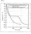
- FIG. 3 illustrates temporal changes in temperature of the thermocouple immersed in the hydrogen detection solution, measured when the hydrogen permeability testing device at room temperature was stored in a cooling container kept at around -20°C. Comparative Example with use of the 0.2 M aqueous sodium hydroxide solution was found to cause freezing, since the temperature reached a plateau at around -1°C. In contrast, Example with use of the 90% by mass aqueous sodium silicate solution was found to give a freezing point of -15°C or below, since the temperature was decreased without causing freezing.
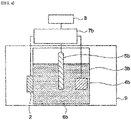
- FIG. 4 is a schematic drawing illustrating a hydrogen permeability testing device used for evaluating the durability.
- the metal specimen 2 manufactured as described above was attached to the acrylic vessel 3b having a hole of 16 mm in diameter.
- the reference electrode 5b and the counter electrode 4b were arranged in the acrylic vessel 3b, so as to simulate the aforementioned hydrogen permeation test.
- the potentiostat/galvanostat 7b and the recorder 8 were connected to the device, but without voltage application or the like during the evaluation of durability.
- the 90% by mass aqueous sodium silicate solution was added as the hydrogen detection solution 6b into the acrylic vessel 3b.
- Comparative Example a device was also prepared, in which the 0.2 M aqueous sodium hydroxide solution was added as the hydrogen detection solution 6b in the acrylic vessel 3b.
- the testing device was kept for about 24 hours, in a cooling container 9 maintained at -20°C.
- Table 2 summarizes occurrence or absence of crack of the acrylic vessel 3b in the hydrogen permeability testing device. Comparative Example with use of the 0.2 M aqueous sodium hydroxide solution was found to cause crack of the acrylic vessel 3b in the hydrogen permeability testing device, and leakage of the hydrogen detection solution 6b.
- Example with use of the 90% by mass aqueous sodium silicate solution was found to cause no crack of the acrylic vessel 3b in the hydrogen permeability testing device. Therefore, it was found that the hydrogen permeability testing device according to the embodiments of the present invention excels in durability at low temperatures.
- Embodiments of the present invention can provide a device capable of evaluating, even at low temperatures, the amount of hydrogen in metal materials, which is one of the dominant factors of sudden crack (delayed fracture) of the metal materials when the metal materials used in various industrial machines including automobiles and transport machines are exposed to a corrosive environment due to the atmosphere, wind, rain, sea salt, snow melting agents for roads or the like.
Landscapes
- Life Sciences & Earth Sciences (AREA)
- Chemical & Material Sciences (AREA)
- Health & Medical Sciences (AREA)
- General Physics & Mathematics (AREA)
- Pathology (AREA)
- Immunology (AREA)
- Physics & Mathematics (AREA)
- Analytical Chemistry (AREA)
- Biochemistry (AREA)
- General Health & Medical Sciences (AREA)
- Electrochemistry (AREA)
- Chemical Kinetics & Catalysis (AREA)
- Molecular Biology (AREA)
- Biodiversity & Conservation Biology (AREA)
- Ecology (AREA)
- Environmental & Geological Engineering (AREA)
- Environmental Sciences (AREA)
- Engineering & Computer Science (AREA)
- Food Science & Technology (AREA)
- Medicinal Chemistry (AREA)
- Testing Resistance To Weather, Investigating Materials By Mechanical Methods (AREA)
- Separation Using Semi-Permeable Membranes (AREA)
- Investigating Or Analyzing Non-Biological Materials By The Use Of Chemical Means (AREA)
Abstract
Description
- The present disclosure relates to a hydrogen permeability testing device capable of evaluating the amount of hydrogen in a metal material even at low temperatures.
- Low fuel consumption of automobiles has been demanded in recent years, from the viewpoint of global environmental issues, for which weight reduction of vehicle bodies has been underway as one of solutions. As an exemplary method for reducing the weight, an effort has been made to strengthen bolts for automobile suspension system, thereby downsizing the bolts. Use of high-strength steel, however, poses a problem that a steel material during use would corrode to produce hydrogen, and the hydrogen if enters the steel would cause delayed fracture. Unlike a high-strength steel plate used for a body frame, the bolts for the automobile suspension system may be exposed not only to the atmosphere, wind and rain when the automobile runs, but also to a strongly corrosive environment with an antifreezing agent such as NaCl or CaCl2 spread in the wintertime for road deicing.
- For prevention of the delayed fracture, a key point is to estimate the amount of hydrogen in a metal material, which is one of the dominant factors. In particular, in the wintertime when the antifreezing agent is spread, some places would experience very low temperatures such as -15°C or below. There is therefore a need for a testing device that can evaluate the amount of hydrogen with high sensitivity, even set at such very low temperatures.
- Various methods have been proposed aiming at measuring the amount of hydrogen in a metal material. For example, thermal desorption spectroscopy such as described in
Non Patent Document 1 has been proposed as a common technique. According to the thermal desorption spectroscopy described inNon Patent Document 1, a metal material is heated, and desorbed hydrogen is detected with use of a mass spectrometer or gas chromatography, whereby the amount and mode of existence of hydrogen in the metal material are evaluated. The amount of entered hydrogen, however, largely varies depending on changes of temperature, humidity, amount of adhered salt or the like, and it has been difficult to evaluate temporal changes in the amount of entered hydrogen by the method described inNon Patent Document 1. - An electrochemical hydrogen permeation method such as described in
Non Patent Document 2 has been proposed as a common technique for evaluating the temporal changes in the amount of entered hydrogen. In the electrochemical hydrogen permeation method, hydrogen is allowed to enter a metal material, with the aid of electrochemical cathode polarization or a corrosion-related cathode reaction, through one face (that is, hydrogen entry face) of the metal material. According to the electrochemical hydrogen permeation method, the entered hydrogen is rapidly oxidized by anodically polarizing the metal face on the opposite side (that is, hydrogen detection face) at an electric potential at which an oxidation reaction represented by H → H+ + e can proceed rapidly enough, and the oxidation current is detected to estimate the amount of hydrogen. - The electrochemical hydrogen permeation method, originally reported by Devanathan et al., has been modified or improved in various ways suitably for applications. For example,
Non Patent Document 3 describes a test method capable of evaluating hydrogen entry in an atmospheric corrosive environment by exposing of the hydrogen entry face to the atmosphere. The method described in Non-PatentDocument 3, uses an aqueous solution that contains NaOH, as a solution for oxidizing hydrogen (that is, a hydrogen detection solution) on the hydrogen detection face. However, when the antifreezing agent needs to be spread in a wintertime, the NaOH-containing aqueous solution freezes at low temperatures in such a wintertime. Freezing of the aqueous solution causes volume expansion of the aqueous solution, and has occasionally damaged the testing device. - As a method for measuring the amount of entered hydrogen at low temperatures, Non Patent Document 4 discloses an electrochemical hydrogen permeation method with use of an organic compound added to a hydrogen detection solution to depress the freezing point. The method described in Non Patent Document 4 uses a 0.2 M KOH solution in alcohol, containing a small amount of water, as a hydrogen detection solution, thus enabling the hydrogen permeability test applicable to a wide temperature range of 230 K to 300 K (-43°C to 27°C).
- Similarly,
Patent Document 1 proposes an electrochemical hydrogen permeation method that uses an organic compound added to a hydrogen detection solution so as to prevent freezing of the hydrogen detection solution.Patent Document 1 discusses a method for depressing the freezing point of the electrolytic solution to -5°C or lower, and discloses a hydrogen permeation test with use of hydrogen detection solutions prepared by adding various ratios of dimethyl sulfoxide (DMSO) to a 0.1 N aqueous NaOH solution. - Patent Document 1:
JP 5754566 B2 -
- Non Patent Document 1: Kenichi Takai, Zairyo-to-Kankyo, 60, 230 (2011)
- Non Patent Document 2: M. A. V. Devanathan and Z. Stachurski, J. Electrochem. Soc., 111, 619 (1964)
- Non Patent Document 3: Tomohiko Omura et al., Zairyo-to-Kankyo, 54, 61 (2005)
- Non Patent Document 4: H. Hagi et al., Transactions of the Japan Institute of Metals, 20, 349 (1979)
- The method described in Non Patent Document 4, however, uses alcohol in the hydrogen detection solution.
- The alcohol in this case is oxidized when anodic polarization is induced on the hydrogen detection face at an electric potential for oxidizing hydrogen, and this oxidation reaction occasionally increases a noise current called a residual current. If the residual current is large, fluctuation in the residual current (i.e. noise) would mask hydrogen permeation current that occurs in response to entry of a trace amount of hydrogen. That is, it has been difficult to detect a trace amount of hydrogen caused by corrosion with high sensitivity.
- The method described in
Patent Document 1 enables detection of a trace amount of hydrogen caused by corrosion, etc. by using DMSO as an organic compound to reduce the residual current. The method described inPatent Document 1 has, however, been aimed at depressing the freezing point of the electrolytic solution (that is, a hydrogen detection solution) to - 5°C or below, and has not necessarily been sufficient for use at very low temperatures such as -15°C or below. That is, Example described inPatent Document 1 are guessed to be difficult to carry out the hydrogen permeation test at very low temperatures such as -15°C or below, since the freezing point of the electrolytic solution (that is, the hydrogen detection solution) is - 12°C at the lowest. - As another method for enabling the hydrogen permeation test at very low temperatures, a method adding a large amount of sodium hydroxide having been used conventionally as an inorganic substance is considered. This is because addition of a large amount of sodium hydroxide can largely depress the freezing point. Such addition of a large amount of sodium hydroxide, however, excessively increases pH of the solution. This unfortunately corrodes a metal plating such as Ni, Pd used for the hydrogen detection face, increases the residual current, making it difficult to detect a trace amount of hydrogen.
- Embodiments of the present invention have been made under such circumstances, and an object of which is to provide a hydrogen permeability testing device capable of estimating the amount of hydrogen in a metal material, over a wide temperature range from very low temperatures at the freezing point or below, up to room temperature.
- An
aspect 1 of the present invention is directed to a hydrogen permeability testing device for measuring the amount of hydrogen entering a metal material by using an electrochemical hydrogen permeation method, wherein the hydrogen permeability testing device comprises: - a metal specimen having a hydrogen entry face through which hydrogen enters, a hydrogen detection face on which the entered hydrogen is detected, and a metal plating which is formed on the hydrogen detection face to efficiently detect the entered hydrogen;
- a reference electrode and a counter electrode for making an electrochemical reaction progress;
- an electrolytic vessel that is provided on a side of the hydrogen detection face, houses the reference electrode and the counter electrode, and contains an aqueous sodium silicate solution having a freezing point of 0°C or lower and capable of suppressing a residual current to 10 nA/cm2 or below when an electric potential of the hydrogen detection face is set at -1 V to 1 V relative to the reference electrode; and
- a measurement unit which measures the amount of hydrogen based on a current value resulted from the electrochemical reaction.
- An
aspect 2 of embodiments of the present invention is directed to the hydrogen permeability testing device according to theaspect 1, wherein a relationship between Baumé degree Bh of the aqueous sodium silicate solution and an operating temperatureT (°C) satisfies T ≥ -0.5 × exp (0.09 × Bh). - An
aspect 3 of embodiments of the present invention is directed to the hydrogen permeability testing device according to theaspect - An aspect 4 of embodiments of the present invention relates to the hydrogen permeability testing device according to any one of the
aspects 1 to 3, wherein a concentration of a sodium silicate solution in the aqueous sodium silicate solution is 10% by mass or higher. - An
aspect 5 of embodiments of the present invention is directed to the hydrogen permeability testing device according to any one of theaspects 1 to 4, wherein the metal plating is formed of any one of Ni, Pd and Au. - An
aspect 6 of embodiments of the present invention relates to a method for measuring the amount of hydrogen, wherein the method comprising: - preparing the hydrogen permeability testing device according to any one of the
aspects 1 to 5; - leaving the hydrogen permeability testing device to stand for 5 hours or longer after the preparing; and
- measuring, after the leaving for 5 hours or longer, the amount of hydrogen based on a current value resulted from the electrochemical reaction.
- According to the embodiments of the present invention, the amount of hydrogen in a metal material can be measured over a wide temperature range from very low temperatures at the freezing point or below, up to room temperature.
-
-
Fig. 1 is a schematic drawing illustrating a hydrogen permeability testing device according to the embodiments of the present invention. -
Fig. 2 is a graph illustrating relation between test temperatures and hydrogen permeability coefficients in Example. -
Fig. 3 is a graph illustrating temporal changes in temperature by a thermocouple placed in hydrogen detection solutions in Example. -
Fig. 4 is a schematic drawing illustrating a hydrogen permeability testing device used for evaluating durability in Example. - Aiming at solving the aforementioned problem, the inventors of the present application have intensively studied in pursuit of that a hydrogen detection solution does not freeze even at lower temperatures at the freezing point or below (for example, -15°C or below). As a common method for depressing the freezing point of a solvent, a method utilizing of a phenomenon of freezing point depression due to addition of an inorganic substance or an organic substance is exemplified. However, as mentioned above, there has been a problem that the added inorganic substance or the organic substance has increased residual current, or promoted corrosion of the metal material used for the hydrogen detection face.
- The inventors have intensively studied a hydrogen permeability testing device capable of (1) causing a small residual current when anodically polarizing at an electric potential for oxidizing hydrogen on the hydrogen detection face, (2) causing no corrosion of the metal material concerned, and (3) causing no damage on the hydrogen permeability testing device even at very low temperatures at the freezing point or below (for example, -15°C or below). The inventors consequently found that the residual current can be reduced without corroding the metal material concerned, by using a concentrated aqueous sodium silicate solution (that is, soda silicate) as the hydrogen detection solution in a predetermined structure. The inventors also found that the amount of hydrogen can be measured without damaging the hydrogen permeability testing device, even at very low temperatures which are the freezing point or below. The concentrated aqueous sodium silicate solution is, however, highly viscous and difficult to handle, as compared with aqueous sodium hydroxide solution having been used conventionally as the hydrogen detection solution. Therefore, the concentrated aqueous sodium silicate solution has not been used conventionally for the hydrogen permeability testing device.
- A hydrogen permeability testing device according to the embodiments of the present invention will be detailed referring to
Fig. 1. Fig. 1 is a schematic drawing illustrating a hydrogenpermeability testing device 1 according to the embodiments of the present invention. A hydrogenpermeability testing device 1 according to the embodiments of the present invention has ametal specimen 2,electrolytic vessels recorder 8. Note that the potentiostat/galvanostat 7b and therecorder 8 constitute the "measurement unit" specified in CLAIMS. - The two
electrolytic vessels metal specimen 2 in between. In each of theelectrolytic vessels metal specimen 2 is contacted with a later-describedsolution 6a or ahydrogen detection solution 6b is provided at a part where themetal specimen 2 is attached. Theelectrolytic vessel 3a contains thesolution 6a for making hydrogen enter themetal specimen 2. Thesolution 6a may be a solution having been used in a conventional hydrogen permeability testing device, and is a 0.1 M NaOH solution as an example. In thesolution 6a, acounter electrode 4a is immersed. The potentiostat/galvanostat 7a is connected to themetal specimen 2 and thecounter electrode 4a. Theelectrolytic vessel 3b contains thehydrogen detection solution 6b. Thehydrogen detection solution 6b will be detailed later. In thehydrogen detection solution 6b, acounter electrode 4b and areference electrode 5b are immersed. The potentiostat/galvanostat 7b is connected to themetal specimen 2, thecounter electrode 4b, and thereference electrode 5b. Therecorder 8 is connected to the potentiostat/galvanostat 7b. - The hydrogen
permeability testing device 1 according to the embodiments of the present invention measures the amount of hydrogen that enters themetal specimen 2, with use of an electrochemical hydrogen permeation method. The electrochemical hydrogen permeation method per se has been known conventionally as a method for measuring a hydrogen permeability coefficient in steel plate. InFig. 1 , a surface of themetal specimen 2 in theelectrolytic vessel 3a on the left side (may be occasionally referred to as "cathode side", hereinafter) is cathodically polarized at a constant electric potential or a constant current to generate and charge hydrogen. On the other hand, in theelectrolytic vessel 3b on the right side (may be occasionally referred to as "anode side", hereinafter), themetal specimen 2 is anodically polarized at a constant electric potential. This oxidizes hydrogen having permeated through themetal specimen 2 into hydrogen ion to produce oxidation-induced current, and the amount of permeated hydrogen can be determined from the current value. A structure on the cathode side is not limited specially, and any one of conventional structures is applicable for it. Note that, in the embodiments of the present invention, the structure on the cathode side is omissible. That is, in the embodiments of the present invention, a structure as illustrated inFig. 4 described later may be applied. Generation and charging of hydrogen in this case are enabled, for example, by making the cathode side of themetal specimen 2 corrode in the atmosphere, etc.. Themetal specimen 2 and structures of the anode side will be explained below. - The
metal specimen 2 is a target to be measured for the amount of hydrogen. Themetal specimen 2 may have any shape of plate, rod, bolt or the like. Themetal specimen 2 illustrated inFig. 1 has a plate shape. For the plate shape, the thickness is preferably 0.1 mm to 10 mm. Themetal specimen 2 illustrated inFig. 1 has ahydrogen entry face 2a through which hydrogen enters, and ahydrogen detection face 2b on which the entered hydrogen is detected. Themetal specimen 2 may have strain introduced to the surface thereof by mechanical working such as cutting or polishing during manufacture. Results of measurement of the amount of hydrogen, especially the diffusion coefficient of hydrogen, may vary with the introduced strain. Therefore, it is preferable to electrolytically polish so that a position at a depth of 10 µm or deeper below the metal surface of thehydrogen detection face 2b will expose. - On the
hydrogen detection face 2b, a metal plating is formed. With the metal plating thus formed, a trace amount of hydrogen can be easily detected. Specifically, this reduces a passivation-maintaining current of thehydrogen detection face 2b, and makes the oxidation reaction represented by H → H+ + e smoothly progress. The passivation-maintaining current is a sort of the residual current. Reduction of the passivation-maintaining current can reduce the residual current, and enables easy detection of a trace amount of hydrogen. Type of the metal plating is preferably selected from materials having a small passivation-maintaining current, a dense and poreless structure, such as Ni plating, Pd plating, or Au plating. Method for plating is preferably electroplating, electroless plating, or vacuum evaporation by sputtering since these methods are easy to controll plating thickness, and can suppress unnecessary entry of hydrogen. - Too small plating thickness may cause exposure of the base, resulting in increase of the passivation-maintaining current, and delay of the oxidation reaction represented by H → H+ + e. The plating thickness is therefore preferably 1 nm or thicker, and more preferably 10 nm or thicker. Meanwhile if the plating thickness is too large, hydrogen diffusion in the plating acts as a rate-limiting process, so that the hydrogen diffusion coefficient may be underestimated. The plating thickness is therefore preferably 1000 nm or thinner, and more preferably 500 nm or thinner.
- The
hydrogen detection solution 6b contained in theelectrolytic vessel 3b is an electrolyte solution that ionizes hydrogen having been permeated through themetal specimen 2. Thehydrogen detection solution 6b in the embodiments of the present invention is aqueous sodium silicate solution. Use of the aqueous sodium silicate solution can suppress the passivation-maintaining current of thehydrogen detection face 2b at room temperature, without corroding the anode side of themetal material 2, and can consequently suppress the residual current down to 10 nA/cm2 or below. The residual current, if 10 nA/cm2 or below, is considered to be suppressed enough, and enables highly sensitive measurement of hydrogen permeation current. The residual current is preferably reduced to 8 nA/cm2 or below, and more preferably 5 nA/cm2 or below. The residual current is most preferably 0 nA/cm2. - The aqueous sodium silicate solution may be prepared by adding sodium silicate solution to water. Note that aqueous sodium hydroxide solution may be used in place of water. When using the aqueous sodium hydroxide solution, the concentration of sodium hydroxide preferably ranges from 0% by mass to 10% by mass, in order to suppress the residual current from increasing. The sodium silicate solution is usually represented by a molecular formula Na2O·nSiO2·mH2O. Coefficient n represents a molar ratio of SiO2 to Na2O. It is called sodium orthosilicate if the molar ratio n is 0.5, and is called sodium metasilicate if the molar ratio n is 1. Both of them are crystalline and usually in the form of powder. It has an amorphous form if the molar ratio n is larger than 1, enables continuous variation in the molar ratio n, and usually exists in the form of aqueous solution called water glass, or soda silicate, etc.. Note that the term "sodium silicate solution" in this specification means commercially available undiluted solution of sodium silicate solution. Meanwhile, the term "aqueous sodium silicate solution" means a solution obtained by diluting the sodium silicate solution with water.
- JIS standard (JIS K1408: 1966) specifies sodium silicate Type 1 (SiO2: 35 to 38%, Na2O: 17 to 19%), sodium silicate Type 2 (SiO2: 34 to 36%, Na2O: 14 to 15%), sodium silicate Type 3 (SiO2: 28 to 30%, Na2O: 9 to 10%), sodium metasilicate Type 1 (SiO2: 27.5 to 29%, Na2O: 28.5 to 30%), and sodium metasilicate Type 2 (SiO2: 19 to 22%, Na2O: 20 to 22%). That is, the sodium silicate solution contains 19 to 38% by mass of SiO2, 9 to 30% by mass of Na2O, and the balance is almost water. In the embodiments of the present invention, the molar ratio n is preferably 3.5 or smaller, since too large molar ratio n may result in insufficient depression of freezing point. The molar ratio is more preferably 2.5 or smaller, and even more preferably 2.2 or smaller. The lower limit of the molar ratio n, although not specifically limited, is preferably 1.0 or larger from the viewpoint of reducing the viscosity, and is more preferably 1.5 or larger.
- In order to suppress the passivation-maintaining current of the metal plating on the
hydrogen detection face 2b, pH of the aqueous sodium silicate solution is preferably kept in the alkaline range. Too low pH may fail in passivating thehydrogen detection face 2b. The pH is therefore preferably 8 or higher, and more preferably 10 or higher. On the other hand, too high pH results in excessive increase of the passivation-maintaining current, so that the pH is preferably 14 or lower, and more preferably 13.5 or lower. The pH may be measured by a usual method, for example, by using of pH meter or pH test paper. The pH of the aqueous sodium silicate solution may vary depending on the concentration of the aqueous sodium silicate solution described later ,etc.. Therefore, it is preferable that the aqueous sodium silicate solution, prepared with determining the concentration, the aforementioned molar ratio n, and so forth, has the pH within the aforementioned preferred range as a result. - Hydrogen detection at low temperatures may damage the hydrogen
permeability testing device 1 due to freeze of thehydrogen detection solution 6b and the volume expansion. Hence, in the embodiments of the present invention, the Baumé degree Bh of the aqueous sodium silicate solution in thehydrogen detection solution 6b is preferably increased to sufficiently depress the freezing point. The Baumé degree Bh is a measurement unit of specific gravity. The inventors found by studying intensively that it is preferable to adjust a relationship between the Baumé degree Bh of the aqueous sodium silicate solution and operating temperature T (°C) so as to satisfy "T ≥ -0.5 × exp(0.09 × Bh)". A value on the right side of the above relational expression is set to a temperature higher than the freezing point of the aqueous sodium silicate solution, that is, an appropriate temperature at which the aqueous sodium silicate solution would not freeze. Specifically, the sodium silicate solution is preferably added to water or the like, so as to adjust the Baumé degree Bh to 26 or larger if the lower limit of the operating temperature T is -5°C or above; to 33 or larger for a lower limit of -10°C or above; and to 41 or larger for a lower limit of -20°C or above. Note that the freezing point of the aqueous sodium silicate solution itself is 0°C or lower, preferably -5°C or lower, more preferably -10°C or lower, and even more preferably -15°C or lower. - For hydrogen detection at low temperatures, too low concentration of the sodium silicate solution in the aqueous sodium silicate solution may fail in sufficiently depressing the freezing point, and may damage the hydrogen
permeability testing device 1. The concentration of the aqueous sodium silicate solution is therefore preferably 10% by mass or higher. The content is more preferably 20% by mass or higher, and even more preferably 40% by mass or higher. On the other hand, too high concentration of the aqueous sodium silicate solution excessively increases the viscosity to make the handling difficult. The concentration of the aqueous sodium silicate solution is therefore preferably 98% by mass or lower. The concentration is more preferably 95% by mass or lower. Note that although variation in the molar ratio SiO2/Na2O in the sodium silicate solution to be used may vary the preferred concentration range, a desired effect can be obtained regardless of such variation in the molar ratio of the sodium silicate solution, within the aforementioned preferred concentration ranges. - Since the sodium silicate solution is highly viscous, when mixing the sodium silicate solution with water or the like for use air bubbles may be inevitably mixed therein during the mixing. The air bubbles, if adsorbed on the
metal specimen 2, suppress the electrochemical reaction on thehydrogen detection face 2b. The aqueous sodium silicate solution therefore needs to remove the air bubbles mixed therein. The method for removing the air bubbles is preferably as follows. That is, first, the sodium silicate solution is mixed with water or the like, and the mixed solution is contained in theelectrolytic vessel 3b. Thecounter electrode 4b, thereference electrode 5b, and so forth are arranged, that is, the preparation before measuring the amount of hydrogen is completed, and then the arrangement is left in this state for 5 hours or longer. The leaving time is preferably 8 hours or longer, and more preferably 12 hours or longer. This successfully expels the air bubbles entrained in the sodium silicate aqueous solution. The leaving time is preferably 100 hours or shorter from the viewpoint of work efficiency, and is more preferably 80 hours or shorter. By using the aqueous sodium silicate solution, from which the air bubbles are removed, for the measurement, the amount of hydrogen can be appropriately measured based on a current value resulted from the electrochemical reaction described later. - The
reference electrode 5b and thecounter electrode 4b are electrodes for anodically polarizing thehydrogen detection face 2b at an electric potential for oxidizing hydrogen. For thereference electrode 5b, generally commercially available silver-silver chloride electrode, a saturated calomel electrode, or the like is preferably used, so as to stabilize the electric potential in thehydrogen detection solution 6b. Hydrogen detection at low temperatures may, however, freeze the internal solution of the silver-silver chloride electrode or the saturated calomel electrode. Hence, for the hydrogen detection at low temperatures, a noble metal such as Pt, Ag, or Ir is preferably used as a pseudo-reference electrode. Thereference electrode 5b may have any shape of rod, plate, or spiral. For thecounter electrode 4b, it is preferable to use a noble metal such as Pt, Ag, or Ir which is non-susceptible itself to redox reaction. Thecounter electrode 4b may have any shape of rod, plate, or spiral. - The potentiostat/
galvanostat 7b measures a current value obtainable from thehydrogen detection face 2b. The potentiostat/galvanostat 7b may be any of conventional devices capable of measuring fine current. The potentiostat/galvanostat 7b is also preferably allowed for electric potential control, so that thehydrogen detection face 2b may be anodically polarized at an electric potential at which the oxidation reaction represented by H → H+ + e can progress rapidly enough. The electric potential of thehydrogen detection face 2b is set within the range from -1 V to 1 V with respect to thereference electrode 5b, so as to lower the passivation-maintaining current at thehydrogen detection face 2b. The electric potential of thehydrogen detection face 2b is preferably set to -500 mV or above, and more preferably 0 V or above, with respect to thereference electrode 5b. The electric potential of thehydrogen detection face 2b is preferably set to 800 mV or below, and more preferably 500 mV or below, with respect to thereference electrode 5b. With the electric potential of thehydrogen detection face 2b set within the range from -1 V to 1 V, and with use of the aforementionedappropriate metal specimen 2 and the aqueous sodium silicate solution, the passivation-maintaining current can be reduced, and the residual current can be suppressed to 10 nA/cm2 or below as a result. Therecorder 8 measures and records the current value that corresponds to the amount of permeated hydrogen on thehydrogen detection face 2b. Any of conventional devices is applicable to therecorder 8. - Next, Example of the hydrogen permeability testing device according to the embodiments of the present invention will be specifically described, in comparison with Comparative Example. The following Example is, however, not intended to limit the present invention, and can be carried out with appropriate modifications within a range that can conform to the gist described previously or later. Also any of such modifications is included in the scope of the present invention.
- A specimen of 32 mm in diameter and 0.5 mm thick was manufactured from a commercially available SCM435 steel material. The surface of the specimen was wet-polished with an emery paper No. 1500, washed with water, degreased with acetone, and dried. Both surfaces of the specimen were then electrolytically polished using a chromic acid-saturated phosphoric acid solution, and one face of the specimen on the side of the hydrogen detection face was plated with Ni in a Watts bath. The electropolishing was carried out so that a position at a depth of 10 µm to 50 µm from the surface of the specimen exposes. The thickness of the Ni plating was adjusted to 100 nm to 1000 nm.
- The thus manufactured metal specimen was sandwiched between two acrylic vessels (that is, electrolytic vessels) each having a hole of 8 mm in diameter. Into the container on the side of the hydrogen detection face, an aqueous sodium silicate solution prepared by adding 10 wt% of water to sodium silicate solution Type 1 (from Kishida Chemical Co., Ltd.) was added as the hydrogen detection solution (that is, 90% by mass aqueous sodium silicate solution was added). For Comparative Example, an experiment was concurrently conducted with use of a 0.2 M aqueous sodium hydroxide solution, whose concentration would not increase the passivation-maintaining current, as the hydrogen detection solution. The Baumé degrees of the 90% by mass aqueous sodium silicate solution and the 0.2 M aqueous sodium hydroxide solution at room temperature (about 20°C) were 52.6 and 0, respectively. The Baumé degree was estimated by measuring the weight and volume of the thus formulated solutions, with a weight scale and a measuring cylinder, respectively. The molar ratio SiO2/Na2O of the aqueous sodium
silicate solution Type 1 used here was approximately 2. pH of the 90% by mass aqueous sodium silicate solution was 13 when measured with a pH meter. - In order to promote passivation of Ni applied to the hydrogen detection face, the hydrogen detection face was anodically polarized while using platinum as the counter electrode, and iridium as the reference electrode, at an electric potential of 0.15 V relative to iridium. The aqueous sodium silicate solution was then leaved to stand for 12 hours or longer, so as to remove the air bubbles mixed therein. The residual current was then checked as being 10 nA/cm2 or lower.
- A thermocouple was immersed in the hydrogen detection solution for temperature measurement. For an experiment maintaining at low temperatures equal to or lower than room temperature, the hydrogen permeability testing device was kept in a cooling container. When a test is conducted at room temperature, the test was conducted indoor, without using the cooling container, while setting the room temperature to around 18°C to 21°C. After checking that the test temperature was constant, a solution prepared by adding 40 vol% of ethylene glycol as an antifreezing agent to a 0.2 N aqueous NaOH solution was added in the vessel on the side of the hydrogen entry face.
- On the cathode side, the hydrogen entry face of the specimen was cathodically polarized at a current density of 1 µA/mm2 with use of platinum as the counter electrode, thereby making hydrogen enter the metal specimen. Current value obtained from the hydrogen detection face was measured as the hydrogen permeation current, with use of a potentiostat/galvanostat. The electric potential of the metal specimen was set to 0.15 V relative to iridium. The hydrogen permeability coefficient was then determined from the equation below, with use of the area and the thickness of the specimen.

- The test was terminated 90 minutes after the start of the cathode polarization, and maximum values of the hydrogen permeability coefficient obtained at the individual test temperatures are summarized in Table 1 and
Fig. 2. Fig. 2 is a graph illustrating relation between the test temperature and the hydrogen permeability coefficient. Note that in Comparative Example in which the 0.2 M aqueous sodium hydroxide solution was used, the hydrogen detection solution was freezed approximately at -1°C or below. The hydrogen permeation test at -1°C or below was therefore not conducted when the 0.2 M aqueous sodium hydroxide solution was used in the test. As can be understood from Table 1 andFig. 2 , Example with use of the 90% by mass aqueous sodium silicate solution showed a maximum hydrogen permeability coefficient, which is equivalent to that obtainable in a case with use of a conventional aqueous sodium hydroxide solution. Example was also successful in detecting the amount of hydrogen even at -19.2°C. Therefore, it was found that the hydrogen permeability testing device according to the embodiments of the present invention can measure the amount of hydrogen in the metal material, over a wide temperature range from very low temperatures such as -15°C or below up to room temperature. - The freezing point of the 90% by mass aqueous sodium silicate solution was checked.
Fig. 3 illustrates temporal changes in temperature of the thermocouple immersed in the hydrogen detection solution, measured when the hydrogen permeability testing device at room temperature was stored in a cooling container kept at around -20°C. Comparative Example with use of the 0.2 M aqueous sodium hydroxide solution was found to cause freezing, since the temperature reached a plateau at around -1°C. In contrast, Example with use of the 90% by mass aqueous sodium silicate solution was found to give a freezing point of -15°C or below, since the temperature was decreased without causing freezing.[Table 1] Hydrogen detection solution Test temperature (°C) Hydrogen permeability coefficient (nA/cm) Category 90% aqueous sodium silicate solution 20.5 167 Example -1.2 46 -19.2 20 0.2 M aqueous sodium hydroxide solution 18.9 179 Comparative Example 0 57 - Durability of the hydrogen permeability testing device was evaluated.
Fig. 4 is a schematic drawing illustrating a hydrogen permeability testing device used for evaluating the durability. As illustrated inFig. 4 , themetal specimen 2 manufactured as described above was attached to theacrylic vessel 3b having a hole of 16 mm in diameter. In this durability evaluation, thereference electrode 5b and thecounter electrode 4b were arranged in theacrylic vessel 3b, so as to simulate the aforementioned hydrogen permeation test. Also the potentiostat/galvanostat 7b and therecorder 8 were connected to the device, but without voltage application or the like during the evaluation of durability. The 90% by mass aqueous sodium silicate solution was added as thehydrogen detection solution 6b into theacrylic vessel 3b. As Comparative Example, a device was also prepared, in which the 0.2 M aqueous sodium hydroxide solution was added as thehydrogen detection solution 6b in theacrylic vessel 3b. For evaluation of the durability of the hydrogen permeability testing device at low temperatures, the testing device was kept for about 24 hours, in a cooling container 9 maintained at -20°C. Table 2 summarizes occurrence or absence of crack of theacrylic vessel 3b in the hydrogen permeability testing device. Comparative Example with use of the 0.2 M aqueous sodium hydroxide solution was found to cause crack of theacrylic vessel 3b in the hydrogen permeability testing device, and leakage of thehydrogen detection solution 6b. In contrast, Example with use of the 90% by mass aqueous sodium silicate solution was found to cause no crack of theacrylic vessel 3b in the hydrogen permeability testing device. Therefore, it was found that the hydrogen permeability testing device according to the embodiments of the present invention excels in durability at low temperatures.[Table 2] Hydrogen detection solution Damage of vessel kept under cooling Category 90% aqueous sodium silicate solution Not damaged Example 0.2 M aqueous sodium hydroxide solution Damaged Comparative Example - This application claims priority based on
Japanese Patent Application No. 2019-165535 filed on September 11, 2019 Japanese Patent Application No. 2019-165535 - Embodiments of the present invention can provide a device capable of evaluating, even at low temperatures, the amount of hydrogen in metal materials, which is one of the dominant factors of sudden crack (delayed fracture) of the metal materials when the metal materials used in various industrial machines including automobiles and transport machines are exposed to a corrosive environment due to the atmosphere, wind, rain, sea salt, snow melting agents for roads or the like.
-
- 1: Hydrogen permeability testing device
- 2: Metal specimen
- 3a, 3b: Electrolytic vessel
- 4a, 4b: Counter electrode
- 5b: Reference electrode
- 6b: Hydrogen detection vessel
- 7a, 7b: Potentiostat/galvanostat
- 8: Recorder
Claims (15)
- A hydrogen permeability testing device for measuring an amount of hydrogen entering a metal material by using an electrochemical hydrogen permeation method, wherein the hydrogen permeability testing device comprises:a metal specimen having a hydrogen entry face through which hydrogen enters, a hydrogen detection face on which the entered hydrogen is detected, and a metal plating which is formed on the hydrogen detection face to efficiently detect the entered hydrogen;a reference electrode and a counter electrode for making an electrochemical reaction progress;an electrolytic vessel that is provided on a side of the hydrogen detection face, houses the reference electrode and the counter electrode, and contains an aqueous sodium silicate solution having a freezing point of 0°C or lower and capable of suppressing a residual current to 10 nA/cm2 or below when an electric potential of the hydrogen detection face is set at -1 V to 1 V relative to the reference electrode; anda measurement unit which measures the amount of hydrogen based on a current value resulted from the electrochemical reaction.
- The hydrogen permeability testing device according to claim 1, wherein a relationship between Baume degree Bh of the aqueous sodium silicate solution and an operating temperature T (°C) satisfies T ≥ -0.5 × exp(0.09 × Bh).
- The hydrogen permeability testing device according to claim 1 or 2, wherein a molar ratio of SiO2/Na2O in the aqueous sodium silicate solution is 3.5 or smaller.
- The hydrogen permeability testing device according to claim 1 or 2, wherein a concentration of a sodium silicate solution in the aqueous sodium silicate solution is 10% by mass or higher.
- The hydrogen permeability testing device according to claim 3, wherein a concentration of a sodium silicate solution in the aqueous sodium silicate solution is 10% by mass or higher.
- The hydrogen permeability testing device according to claim 1 or 2, wherein the metal plating is formed of any one of Ni, Pd and Au.
- The hydrogen permeability testing device according to claim 3, wherein the metal plating is formed of any one of Ni, Pd and Au.
- The hydrogen permeability testing device according to claim 4, wherein the metal plating is formed of any one of Ni, Pd and Au.
- The hydrogen permeability testing device according to claim 5, wherein the metal plating is formed of any one of Ni, Pd and Au.
- A method for measuring an amount of hydrogen, wherein the method comprises:preparing the hydrogen permeability testing device according to claim 1 or 2;leaving the hydrogen permeability testing device to stand for 5 hours or longer after the preparing; andmeasuring, after the leaving for 5 hours or longer, the amount of hydrogen based on a current value resulted from the electrochemical reaction.
- A method for measuring an amount of hydrogen, wherein the method comprises:preparing the hydrogen permeability testing device according to claim 3;leaving the hydrogen permeability testing device to stand for 5 hours or longer after the preparing; andmeasuring, after the leaving for 5 hours or longer, the amount of hydrogen based on a current value resulted from the electrochemical reaction.
- A method for measuring an amount of hydrogen, wherein the method comprises:preparing the hydrogen permeability testing device according to claim 4;leaving the hydrogen permeability testing device to stand for 5 hours or longer after the preparing; andmeasuring, after the leaving for 5 hours or longer, the amount of hydrogen based on a current value resulted from the electrochemical reaction.
- A method for measuring an amount of hydrogen, wherein the method comprises:preparing the hydrogen permeability testing device according to claim 5;leaving the hydrogen permeability testing device to stand for 5 hours or longer after the preparing; andmeasuring, after the leaving for 5 hours or longer, the amount of hydrogen based on a current value resulted from the electrochemical reaction.
- A method for measuring an amount of hydrogen, wherein the method comprises:preparing the hydrogen permeability testing device according to claim 6;leaving the hydrogen permeability testing device to stand for 5 hours or longer after the preparing; andmeasuring, after the leaving for 5 hours or longer, the amount of hydrogen based on a current value resulted from the electrochemical reaction.
- A method for measuring an amount of hydrogen, wherein the method comprises:preparing the hydrogen permeability testing device according to any one of claims 7 to 9;leaving the hydrogen permeability testing device to stand for 5 hours or longer after the preparing; andmeasuring, after the leaving for 5 hours or longer, the amount of hydrogen based on a current value resulted from the electrochemical reaction.
Applications Claiming Priority (2)
| Application Number | Priority Date | Filing Date | Title |
|---|---|---|---|
| JP2019165535A JP7149242B2 (en) | 2019-09-11 | 2019-09-11 | Hydrogen permeation test device |
| PCT/JP2020/033116 WO2021049379A1 (en) | 2019-09-11 | 2020-09-01 | Hydrogen permeation test device |
Publications (3)
| Publication Number | Publication Date |
|---|---|
| EP4012382A1 true EP4012382A1 (en) | 2022-06-15 |
| EP4012382A4 EP4012382A4 (en) | 2022-10-12 |
| EP4012382B1 EP4012382B1 (en) | 2024-03-13 |
Family
ID=74864002
Family Applications (1)
| Application Number | Title | Priority Date | Filing Date |
|---|---|---|---|
| EP20863388.3A Active EP4012382B1 (en) | 2019-09-11 | 2020-09-01 | Hydrogen permeation test device |
Country Status (6)
| Country | Link |
|---|---|
| US (1) | US12656302B2 (en) |
| EP (1) | EP4012382B1 (en) |
| JP (1) | JP7149242B2 (en) |
| CN (1) | CN114364975B (en) |
| FI (1) | FI4012382T3 (en) |
| WO (1) | WO2021049379A1 (en) |
Families Citing this family (11)
| Publication number | Priority date | Publication date | Assignee | Title |
|---|---|---|---|---|
| CN112114169B (en) * | 2020-08-26 | 2021-08-10 | 哈尔滨工业大学 | Double-electrolytic-cell device for micro-area electrochemical test and using method thereof |
| WO2022208611A1 (en) * | 2021-03-29 | 2022-10-06 | 日本電信電話株式会社 | Surface hydrogen amount analysis method, surface hydrogen amount analysis device, and surface hydrogen amount analysis program |
| WO2023135700A1 (en) * | 2022-01-13 | 2023-07-20 | 日本電信電話株式会社 | Concrete test piece, production method for concrete test piece, and method for measuring hydrogen content |
| CN114384002B (en) * | 2022-01-20 | 2024-03-01 | 江苏徐工工程机械研究院有限公司 | Methods for testing the corrosion resistance of ceramic membranes and methods for testing the quality of ceramic membranes |
| JP7845072B2 (en) * | 2022-06-16 | 2026-04-14 | 株式会社Ihi | Test equipment |
| CN114993889A (en) * | 2022-08-04 | 2022-09-02 | 有研工程技术研究院有限公司 | A kind of hydrogen permeation test method of metal surface hydrogen barrier coating |
| CN115979939B (en) * | 2023-02-13 | 2026-05-15 | 中国石油大学(华东) | An in-situ hydrogen permeation and corrosion coupled high-pressure vessel |
| WO2024218815A1 (en) * | 2023-04-17 | 2024-10-24 | 日本電信電話株式会社 | Metal test piece |
| CN116609232A (en) * | 2023-06-14 | 2023-08-18 | 中国航空制造技术研究院 | Device and method for detecting content of introduced hydrogen in electroplating process of conductor in real time |
| WO2025215762A1 (en) * | 2024-04-10 | 2025-10-16 | Ntt株式会社 | Specimen and method for measuring amount of hydrogen intrusion |
| CN119736575B (en) * | 2024-12-23 | 2026-05-01 | 西安理工大学 | Wear-resistant hydrogen permeation layer of sheet titanium alloy and preparation method thereof |
Family Cites Families (23)
| Publication number | Priority date | Publication date | Assignee | Title |
|---|---|---|---|---|
| JPS5551807A (en) | 1978-10-09 | 1980-04-15 | Toray Ind Inc | Spinning in magnetic field |
| US5266228A (en) * | 1991-08-29 | 1993-11-30 | Basf Corporation | Corrosion-inhibiting automotive coolant solutions containing effective amounts of sodium silicate having a low ratio of silica to sodium oxide |
| JPH06196731A (en) * | 1991-11-25 | 1994-07-15 | Canon Inc | Method for recovering performance of photoelectric conversion body having short-circuited portion |
| JP3495543B2 (en) * | 1997-02-17 | 2004-02-09 | 三菱重工業株式会社 | Evaluation method for creep damage of tempered martensitic steel |
| JP4093675B2 (en) | 1999-03-31 | 2008-06-04 | 株式会社神戸製鋼所 | Manufacturing method of steel sheet for coating with excellent hydrogen embrittlement resistance and corrosion resistance |
| JP2003121406A (en) | 2001-10-19 | 2003-04-23 | Hitachi Ltd | Electrochemical measurement cell for metallic materials |
| KR20060030011A (en) * | 2003-01-29 | 2006-04-07 | 후쿠타니 기쿠코 | Antifreeze, and rust inhibitor which can be used for this |
| FR2877018B1 (en) * | 2004-10-25 | 2007-09-21 | Snecma Moteurs Sa | MICRO ARC OXIDATION PROCESS FOR MAKING A COATING ON A METALLIC SUBSTRATE, AND USE THEREOF |
| JP4533731B2 (en) * | 2004-11-30 | 2010-09-01 | アマノ株式会社 | Electrolyzed water for alkaline cleaning, its production method and production device |
| JP4936781B2 (en) * | 2006-04-26 | 2012-05-23 | 株式会社ネオス | Method for producing weathering steel |
| JP2010013548A (en) | 2008-07-03 | 2010-01-21 | Highway Touhoku:Kk | Road surface antifreezing agent |
| EP2354091B1 (en) * | 2010-02-06 | 2017-11-29 | Cognis IP Management GmbH | Silicate solutions stable in storage |
| JP5754566B2 (en) | 2011-08-26 | 2015-07-29 | Jfeスチール株式会社 | Device for measuring the amount of hydrogen penetrating into metal |
| JP5687645B2 (en) | 2012-03-05 | 2015-03-18 | 日本電信電話株式会社 | Hydrogen storage evaluation method |
| JP6049134B2 (en) | 2012-10-02 | 2016-12-21 | 日本電信電話株式会社 | Method for suppressing hydrogen intrusion into steel |
| CN104685350A (en) * | 2012-10-03 | 2015-06-03 | 杰富意钢铁株式会社 | Measuring device for hydrogen intrusion into metal |
| CN202994715U (en) * | 2012-12-14 | 2013-06-12 | 中国石油大学(华东) | Double-cell test device for hydrogen penetration of metal |
| JP6256757B2 (en) * | 2014-01-15 | 2018-01-10 | 公立大学法人 富山県立大学 | Antifreeze and its usage |
| JP6588806B2 (en) * | 2015-11-16 | 2019-10-09 | アズビル株式会社 | Hydrogen permeation prevention membrane |
| CN108226024B (en) | 2018-03-14 | 2020-12-25 | 中国科学院海洋研究所 | Vehicle-mounted atmospheric corrosion hydrogen permeation monitoring sensor and monitoring method |
| JP7058528B2 (en) | 2018-03-19 | 2022-04-22 | ソーラーフロンティア株式会社 | Mounting structure of solar cell module |
| CN108428948B (en) * | 2018-04-04 | 2020-07-10 | 浙江天地之光电池制造有限公司 | Electrolyte of lead crystal storage battery, preparation method of electrolyte and lead crystal storage battery |
| JP7032651B2 (en) * | 2018-07-17 | 2022-03-09 | 日本電信電話株式会社 | Hydrogen analysis system |
-
2019
- 2019-09-11 JP JP2019165535A patent/JP7149242B2/en active Active
-
2020
- 2020-09-01 US US17/641,781 patent/US12656302B2/en active Active
- 2020-09-01 EP EP20863388.3A patent/EP4012382B1/en active Active
- 2020-09-01 CN CN202080063324.3A patent/CN114364975B/en active Active
- 2020-09-01 WO PCT/JP2020/033116 patent/WO2021049379A1/en not_active Ceased
- 2020-09-01 FI FIEP20863388.3T patent/FI4012382T3/en active
Also Published As
| Publication number | Publication date |
|---|---|
| CN114364975A (en) | 2022-04-15 |
| US20220373506A1 (en) | 2022-11-24 |
| FI4012382T3 (en) | 2024-05-13 |
| CN114364975B (en) | 2024-02-20 |
| JP7149242B2 (en) | 2022-10-06 |
| JP2021043076A (en) | 2021-03-18 |
| EP4012382B1 (en) | 2024-03-13 |
| US12656302B2 (en) | 2026-06-16 |
| EP4012382A4 (en) | 2022-10-12 |
| WO2021049379A1 (en) | 2021-03-18 |
Similar Documents
| Publication | Publication Date | Title |
|---|---|---|
| EP4012382B1 (en) | Hydrogen permeation test device | |
| KR101725747B1 (en) | Apparatus for measuring amount of hydrogen penetrated into metal | |
| JP5700673B2 (en) | Method for measuring amount of hydrogen penetrating into metal and method for monitoring amount of hydrogen penetrating into metal part of moving body | |
| JP5754566B2 (en) | Device for measuring the amount of hydrogen penetrating into metal | |
| CN108072602B (en) | Electrochemical method for accelerating corrosion of stainless steel weld joint area | |
| JP2011179893A (en) | Method for measuring amount of hydrogen penetrated into metal and method for monitoring amount of hydrogen penetrated into metal region of moving body | |
| JP5777098B2 (en) | Method for measuring amount of hydrogen penetrating into metal and method for monitoring amount of hydrogen penetrating into metal part of moving body | |
| CN111684021B (en) | Corrosion protection of metal substrates | |
| JP7492944B2 (en) | Hydrogen charging method and hydrogen embrittlement characteristic evaluation method | |
| US4874434A (en) | Method of treating a titanium structure | |
| Jin et al. | Continuous monitoring of steel corrosion condition in concrete under drying/wetting exposure to chloride solution by embedded MnO2 sensor | |
| JP2013044716A (en) | Method for measuring amount of hydrogen penetrated into metal and method for monitoring amount of hydrogen penetrated into metal portion of moving body | |
| JP5979731B2 (en) | Method for monitoring the amount of hydrogen entering the metal part of a moving object | |
| JP2012083140A (en) | Method for predicting corrosion rate of metal, and prediction system of corrosion life of metal | |
| JP6172097B2 (en) | Monitoring method of intrusion hydrogen amount into steel constituting car body | |
| Huang et al. | Effect of dodecylamine on the corrosion behaviour of zinc in ammonium chloride solution | |
| Levy | Corrosion Inhibitors in Automotive Coolant Media. Action of Polarization Characteristics of Steel | |
| JP6130447B2 (en) | Method for monitoring the amount of hydrogen entering the metal part of a moving object | |
| TWI502196B (en) | Measurement device for intrusion of hydrogen into the metal | |
| Šoljić et al. | Applicability of the paste electrolyte cell for in situ electrochemical testing the surface protection of bronze | |
| JP7776399B2 (en) | Hydrogen charging method and hydrogen embrittlement property evaluation method | |
| WO2024079877A1 (en) | Method for evaluating hydrogen evolution reaction | |
| JP2024065941A (en) | Hydrogen charging method and hydrogen embrittlement characteristic evaluation method | |
| Xiao et al. | Localized electrochemical impedance spectroscopy study on the corrosion behavior of Fe-Cr alloy in the solution with Cl− and SO42− | |
| Rybalka et al. | Simple method for stabilizing solution pH in an electrochemical cell |
Legal Events
| Date | Code | Title | Description |
|---|---|---|---|
| STAA | Information on the status of an ep patent application or granted ep patent |
Free format text: STATUS: THE INTERNATIONAL PUBLICATION HAS BEEN MADE |
|
| PUAI | Public reference made under article 153(3) epc to a published international application that has entered the european phase |
Free format text: ORIGINAL CODE: 0009012 |
|
| STAA | Information on the status of an ep patent application or granted ep patent |
Free format text: STATUS: REQUEST FOR EXAMINATION WAS MADE |
|
| 17P | Request for examination filed |
Effective date: 20220310 |
|
| AK | Designated contracting states |
Kind code of ref document: A1 Designated state(s): AL AT BE BG CH CY CZ DE DK EE ES FI FR GB GR HR HU IE IS IT LI LT LU LV MC MK MT NL NO PL PT RO RS SE SI SK SM TR |
|
| A4 | Supplementary search report drawn up and despatched |
Effective date: 20220909 |
|
| RIC1 | Information provided on ipc code assigned before grant |
Ipc: G01N 27/416 20060101ALI20220905BHEP Ipc: G01N 27/28 20060101ALI20220905BHEP Ipc: G01N 27/26 20060101ALI20220905BHEP Ipc: G01N 17/00 20060101AFI20220905BHEP |
|
| DAV | Request for validation of the european patent (deleted) | ||
| DAX | Request for extension of the european patent (deleted) | ||
| GRAP | Despatch of communication of intention to grant a patent |
Free format text: ORIGINAL CODE: EPIDOSNIGR1 |
|
| STAA | Information on the status of an ep patent application or granted ep patent |
Free format text: STATUS: GRANT OF PATENT IS INTENDED |
|
| INTG | Intention to grant announced |
Effective date: 20230627 |
|
| GRAJ | Information related to disapproval of communication of intention to grant by the applicant or resumption of examination proceedings by the epo deleted |
Free format text: ORIGINAL CODE: EPIDOSDIGR1 |
|
| STAA | Information on the status of an ep patent application or granted ep patent |
Free format text: STATUS: REQUEST FOR EXAMINATION WAS MADE |
|
| GRAP | Despatch of communication of intention to grant a patent |
Free format text: ORIGINAL CODE: EPIDOSNIGR1 |
|
| STAA | Information on the status of an ep patent application or granted ep patent |
Free format text: STATUS: GRANT OF PATENT IS INTENDED |
|
| INTC | Intention to grant announced (deleted) | ||
| INTG | Intention to grant announced |
Effective date: 20231129 |
|
| P01 | Opt-out of the competence of the unified patent court (upc) registered |
Effective date: 20231220 |
|
| GRAS | Grant fee paid |
Free format text: ORIGINAL CODE: EPIDOSNIGR3 |
|
| GRAA | (expected) grant |
Free format text: ORIGINAL CODE: 0009210 |
|
| STAA | Information on the status of an ep patent application or granted ep patent |
Free format text: STATUS: THE PATENT HAS BEEN GRANTED |
|
| AK | Designated contracting states |
Kind code of ref document: B1 Designated state(s): AL AT BE BG CH CY CZ DE DK EE ES FI FR GB GR HR HU IE IS IT LI LT LU LV MC MK MT NL NO PL PT RO RS SE SI SK SM TR |
|
| REG | Reference to a national code |
Ref country code: GB Ref legal event code: FG4D |
|
| REG | Reference to a national code |
Ref country code: CH Ref legal event code: EP |
|
| REG | Reference to a national code |
Ref country code: DE Ref legal event code: R096 Ref document number: 602020027339 Country of ref document: DE |
|
| REG | Reference to a national code |
Ref country code: IE Ref legal event code: FG4D |
|
| REG | Reference to a national code |
Ref country code: SE Ref legal event code: TRGR |
|
| REG | Reference to a national code |
Ref country code: FI Ref legal event code: FGE |
|
| PG25 | Lapsed in a contracting state [announced via postgrant information from national office to epo] |
Ref country code: LT Free format text: LAPSE BECAUSE OF FAILURE TO SUBMIT A TRANSLATION OF THE DESCRIPTION OR TO PAY THE FEE WITHIN THE PRESCRIBED TIME-LIMIT Effective date: 20240313 |
|
| REG | Reference to a national code |
Ref country code: LT Ref legal event code: MG9D |
|
| PG25 | Lapsed in a contracting state [announced via postgrant information from national office to epo] |
Ref country code: GR Free format text: LAPSE BECAUSE OF FAILURE TO SUBMIT A TRANSLATION OF THE DESCRIPTION OR TO PAY THE FEE WITHIN THE PRESCRIBED TIME-LIMIT Effective date: 20240614 |
|
| REG | Reference to a national code |
Ref country code: NL Ref legal event code: MP Effective date: 20240313 |
|
| PG25 | Lapsed in a contracting state [announced via postgrant information from national office to epo] |
Ref country code: HR Free format text: LAPSE BECAUSE OF FAILURE TO SUBMIT A TRANSLATION OF THE DESCRIPTION OR TO PAY THE FEE WITHIN THE PRESCRIBED TIME-LIMIT Effective date: 20240313 Ref country code: RS Free format text: LAPSE BECAUSE OF FAILURE TO SUBMIT A TRANSLATION OF THE DESCRIPTION OR TO PAY THE FEE WITHIN THE PRESCRIBED TIME-LIMIT Effective date: 20240613 |
|
| PG25 | Lapsed in a contracting state [announced via postgrant information from national office to epo] |
Ref country code: ES Free format text: LAPSE BECAUSE OF FAILURE TO SUBMIT A TRANSLATION OF THE DESCRIPTION OR TO PAY THE FEE WITHIN THE PRESCRIBED TIME-LIMIT Effective date: 20240313 |
|
| PG25 | Lapsed in a contracting state [announced via postgrant information from national office to epo] |
Ref country code: RS Free format text: LAPSE BECAUSE OF FAILURE TO SUBMIT A TRANSLATION OF THE DESCRIPTION OR TO PAY THE FEE WITHIN THE PRESCRIBED TIME-LIMIT Effective date: 20240613 Ref country code: LT Free format text: LAPSE BECAUSE OF FAILURE TO SUBMIT A TRANSLATION OF THE DESCRIPTION OR TO PAY THE FEE WITHIN THE PRESCRIBED TIME-LIMIT Effective date: 20240313 Ref country code: HR Free format text: LAPSE BECAUSE OF FAILURE TO SUBMIT A TRANSLATION OF THE DESCRIPTION OR TO PAY THE FEE WITHIN THE PRESCRIBED TIME-LIMIT Effective date: 20240313 Ref country code: GR Free format text: LAPSE BECAUSE OF FAILURE TO SUBMIT A TRANSLATION OF THE DESCRIPTION OR TO PAY THE FEE WITHIN THE PRESCRIBED TIME-LIMIT Effective date: 20240614 Ref country code: ES Free format text: LAPSE BECAUSE OF FAILURE TO SUBMIT A TRANSLATION OF THE DESCRIPTION OR TO PAY THE FEE WITHIN THE PRESCRIBED TIME-LIMIT Effective date: 20240313 Ref country code: BG Free format text: LAPSE BECAUSE OF FAILURE TO SUBMIT A TRANSLATION OF THE DESCRIPTION OR TO PAY THE FEE WITHIN THE PRESCRIBED TIME-LIMIT Effective date: 20240313 |
|
| REG | Reference to a national code |
Ref country code: AT Ref legal event code: MK05 Ref document number: 1666182 Country of ref document: AT Kind code of ref document: T Effective date: 20240313 |
|
| PG25 | Lapsed in a contracting state [announced via postgrant information from national office to epo] |
Ref country code: LV Free format text: LAPSE BECAUSE OF FAILURE TO SUBMIT A TRANSLATION OF THE DESCRIPTION OR TO PAY THE FEE WITHIN THE PRESCRIBED TIME-LIMIT Effective date: 20240313 |
|
| PG25 | Lapsed in a contracting state [announced via postgrant information from national office to epo] |
Ref country code: NL Free format text: LAPSE BECAUSE OF FAILURE TO SUBMIT A TRANSLATION OF THE DESCRIPTION OR TO PAY THE FEE WITHIN THE PRESCRIBED TIME-LIMIT Effective date: 20240313 |
|
| PG25 | Lapsed in a contracting state [announced via postgrant information from national office to epo] |
Ref country code: NL Free format text: LAPSE BECAUSE OF FAILURE TO SUBMIT A TRANSLATION OF THE DESCRIPTION OR TO PAY THE FEE WITHIN THE PRESCRIBED TIME-LIMIT Effective date: 20240313 |
|
| PG25 | Lapsed in a contracting state [announced via postgrant information from national office to epo] |
Ref country code: IS Free format text: LAPSE BECAUSE OF FAILURE TO SUBMIT A TRANSLATION OF THE DESCRIPTION OR TO PAY THE FEE WITHIN THE PRESCRIBED TIME-LIMIT Effective date: 20240713 |
|
| PG25 | Lapsed in a contracting state [announced via postgrant information from national office to epo] |
Ref country code: SM Free format text: LAPSE BECAUSE OF FAILURE TO SUBMIT A TRANSLATION OF THE DESCRIPTION OR TO PAY THE FEE WITHIN THE PRESCRIBED TIME-LIMIT Effective date: 20240313 Ref country code: PT Free format text: LAPSE BECAUSE OF FAILURE TO SUBMIT A TRANSLATION OF THE DESCRIPTION OR TO PAY THE FEE WITHIN THE PRESCRIBED TIME-LIMIT Effective date: 20240715 |
|
| PG25 | Lapsed in a contracting state [announced via postgrant information from national office to epo] |
Ref country code: CZ Free format text: LAPSE BECAUSE OF FAILURE TO SUBMIT A TRANSLATION OF THE DESCRIPTION OR TO PAY THE FEE WITHIN THE PRESCRIBED TIME-LIMIT Effective date: 20240313 Ref country code: EE Free format text: LAPSE BECAUSE OF FAILURE TO SUBMIT A TRANSLATION OF THE DESCRIPTION OR TO PAY THE FEE WITHIN THE PRESCRIBED TIME-LIMIT Effective date: 20240313 |
|
| PG25 | Lapsed in a contracting state [announced via postgrant information from national office to epo] |
Ref country code: AT Free format text: LAPSE BECAUSE OF FAILURE TO SUBMIT A TRANSLATION OF THE DESCRIPTION OR TO PAY THE FEE WITHIN THE PRESCRIBED TIME-LIMIT Effective date: 20240313 |
|
| PG25 | Lapsed in a contracting state [announced via postgrant information from national office to epo] |
Ref country code: PL Free format text: LAPSE BECAUSE OF FAILURE TO SUBMIT A TRANSLATION OF THE DESCRIPTION OR TO PAY THE FEE WITHIN THE PRESCRIBED TIME-LIMIT Effective date: 20240313 |
|
| PG25 | Lapsed in a contracting state [announced via postgrant information from national office to epo] |
Ref country code: SK Free format text: LAPSE BECAUSE OF FAILURE TO SUBMIT A TRANSLATION OF THE DESCRIPTION OR TO PAY THE FEE WITHIN THE PRESCRIBED TIME-LIMIT Effective date: 20240313 |
|
| PG25 | Lapsed in a contracting state [announced via postgrant information from national office to epo] |
Ref country code: SM Free format text: LAPSE BECAUSE OF FAILURE TO SUBMIT A TRANSLATION OF THE DESCRIPTION OR TO PAY THE FEE WITHIN THE PRESCRIBED TIME-LIMIT Effective date: 20240313 Ref country code: SK Free format text: LAPSE BECAUSE OF FAILURE TO SUBMIT A TRANSLATION OF THE DESCRIPTION OR TO PAY THE FEE WITHIN THE PRESCRIBED TIME-LIMIT Effective date: 20240313 Ref country code: RO Free format text: LAPSE BECAUSE OF FAILURE TO SUBMIT A TRANSLATION OF THE DESCRIPTION OR TO PAY THE FEE WITHIN THE PRESCRIBED TIME-LIMIT Effective date: 20240313 Ref country code: PT Free format text: LAPSE BECAUSE OF FAILURE TO SUBMIT A TRANSLATION OF THE DESCRIPTION OR TO PAY THE FEE WITHIN THE PRESCRIBED TIME-LIMIT Effective date: 20240715 Ref country code: PL Free format text: LAPSE BECAUSE OF FAILURE TO SUBMIT A TRANSLATION OF THE DESCRIPTION OR TO PAY THE FEE WITHIN THE PRESCRIBED TIME-LIMIT Effective date: 20240313 Ref country code: IS Free format text: LAPSE BECAUSE OF FAILURE TO SUBMIT A TRANSLATION OF THE DESCRIPTION OR TO PAY THE FEE WITHIN THE PRESCRIBED TIME-LIMIT Effective date: 20240713 Ref country code: EE Free format text: LAPSE BECAUSE OF FAILURE TO SUBMIT A TRANSLATION OF THE DESCRIPTION OR TO PAY THE FEE WITHIN THE PRESCRIBED TIME-LIMIT Effective date: 20240313 Ref country code: CZ Free format text: LAPSE BECAUSE OF FAILURE TO SUBMIT A TRANSLATION OF THE DESCRIPTION OR TO PAY THE FEE WITHIN THE PRESCRIBED TIME-LIMIT Effective date: 20240313 Ref country code: AT Free format text: LAPSE BECAUSE OF FAILURE TO SUBMIT A TRANSLATION OF THE DESCRIPTION OR TO PAY THE FEE WITHIN THE PRESCRIBED TIME-LIMIT Effective date: 20240313 |
|
| PG25 | Lapsed in a contracting state [announced via postgrant information from national office to epo] |
Ref country code: IT Free format text: LAPSE BECAUSE OF FAILURE TO SUBMIT A TRANSLATION OF THE DESCRIPTION OR TO PAY THE FEE WITHIN THE PRESCRIBED TIME-LIMIT Effective date: 20240313 |
|
| REG | Reference to a national code |
Ref country code: DE Ref legal event code: R097 Ref document number: 602020027339 Country of ref document: DE |
|
| PG25 | Lapsed in a contracting state [announced via postgrant information from national office to epo] |
Ref country code: IT Free format text: LAPSE BECAUSE OF FAILURE TO SUBMIT A TRANSLATION OF THE DESCRIPTION OR TO PAY THE FEE WITHIN THE PRESCRIBED TIME-LIMIT Effective date: 20240313 |
|
| PG25 | Lapsed in a contracting state [announced via postgrant information from national office to epo] |
Ref country code: DK Free format text: LAPSE BECAUSE OF FAILURE TO SUBMIT A TRANSLATION OF THE DESCRIPTION OR TO PAY THE FEE WITHIN THE PRESCRIBED TIME-LIMIT Effective date: 20240313 |
|
| PLBE | No opposition filed within time limit |
Free format text: ORIGINAL CODE: 0009261 |
|
| STAA | Information on the status of an ep patent application or granted ep patent |
Free format text: STATUS: NO OPPOSITION FILED WITHIN TIME LIMIT |
|
| PG25 | Lapsed in a contracting state [announced via postgrant information from national office to epo] |
Ref country code: DK Free format text: LAPSE BECAUSE OF FAILURE TO SUBMIT A TRANSLATION OF THE DESCRIPTION OR TO PAY THE FEE WITHIN THE PRESCRIBED TIME-LIMIT Effective date: 20240313 |
|
| 26N | No opposition filed |
Effective date: 20241216 |
|
| REG | Reference to a national code |
Ref country code: DE Ref legal event code: R119 Ref document number: 602020027339 Country of ref document: DE |
|
| PG25 | Lapsed in a contracting state [announced via postgrant information from national office to epo] |
Ref country code: SI Free format text: LAPSE BECAUSE OF FAILURE TO SUBMIT A TRANSLATION OF THE DESCRIPTION OR TO PAY THE FEE WITHIN THE PRESCRIBED TIME-LIMIT Effective date: 20240313 Ref country code: MC Free format text: LAPSE BECAUSE OF FAILURE TO SUBMIT A TRANSLATION OF THE DESCRIPTION OR TO PAY THE FEE WITHIN THE PRESCRIBED TIME-LIMIT Effective date: 20240313 |
|
| REG | Reference to a national code |
Ref country code: CH Ref legal event code: PL |
|
| PG25 | Lapsed in a contracting state [announced via postgrant information from national office to epo] |
Ref country code: LU Free format text: LAPSE BECAUSE OF NON-PAYMENT OF DUE FEES Effective date: 20240901 |
|
| GBPC | Gb: european patent ceased through non-payment of renewal fee |
Effective date: 20240901 |
|
| PG25 | Lapsed in a contracting state [announced via postgrant information from national office to epo] |
Ref country code: DE Free format text: LAPSE BECAUSE OF NON-PAYMENT OF DUE FEES Effective date: 20250401 |
|
| PG25 | Lapsed in a contracting state [announced via postgrant information from national office to epo] |
Ref country code: GB Free format text: LAPSE BECAUSE OF NON-PAYMENT OF DUE FEES Effective date: 20240901 |
|
| REG | Reference to a national code |
Ref country code: BE Ref legal event code: MM Effective date: 20240930 |
|
| PG25 | Lapsed in a contracting state [announced via postgrant information from national office to epo] |
Ref country code: BE Free format text: LAPSE BECAUSE OF NON-PAYMENT OF DUE FEES Effective date: 20240930 |
|
| PG25 | Lapsed in a contracting state [announced via postgrant information from national office to epo] |
Ref country code: FR Free format text: LAPSE BECAUSE OF NON-PAYMENT OF DUE FEES Effective date: 20240930 |
|
| PG25 | Lapsed in a contracting state [announced via postgrant information from national office to epo] |
Ref country code: CH Free format text: LAPSE BECAUSE OF NON-PAYMENT OF DUE FEES Effective date: 20240930 |
|
| PG25 | Lapsed in a contracting state [announced via postgrant information from national office to epo] |
Ref country code: IE Free format text: LAPSE BECAUSE OF NON-PAYMENT OF DUE FEES Effective date: 20240901 |
|
| PGFP | Annual fee paid to national office [announced via postgrant information from national office to epo] |
Ref country code: FI Payment date: 20250912 Year of fee payment: 6 |
|
| PGFP | Annual fee paid to national office [announced via postgrant information from national office to epo] |
Ref country code: NO Payment date: 20250909 Year of fee payment: 6 |
|
| PGFP | Annual fee paid to national office [announced via postgrant information from national office to epo] |
Ref country code: SE Payment date: 20250702 Year of fee payment: 6 |
|
| PG25 | Lapsed in a contracting state [announced via postgrant information from national office to epo] |
Ref country code: CY Free format text: LAPSE BECAUSE OF FAILURE TO SUBMIT A TRANSLATION OF THE DESCRIPTION OR TO PAY THE FEE WITHIN THE PRESCRIBED TIME-LIMIT; INVALID AB INITIO Effective date: 20200901 |
|
| PG25 | Lapsed in a contracting state [announced via postgrant information from national office to epo] |
Ref country code: HU Free format text: LAPSE BECAUSE OF FAILURE TO SUBMIT A TRANSLATION OF THE DESCRIPTION OR TO PAY THE FEE WITHIN THE PRESCRIBED TIME-LIMIT; INVALID AB INITIO Effective date: 20200901 |
|
| PG25 | Lapsed in a contracting state [announced via postgrant information from national office to epo] |
Ref country code: TR Free format text: LAPSE BECAUSE OF FAILURE TO SUBMIT A TRANSLATION OF THE DESCRIPTION OR TO PAY THE FEE WITHIN THE PRESCRIBED TIME-LIMIT Effective date: 20240313 |