EP4012282A1 - Portable air purifier - Google Patents
Portable air purifier Download PDFInfo
- Publication number
- EP4012282A1 EP4012282A1 EP21209324.9A EP21209324A EP4012282A1 EP 4012282 A1 EP4012282 A1 EP 4012282A1 EP 21209324 A EP21209324 A EP 21209324A EP 4012282 A1 EP4012282 A1 EP 4012282A1
- Authority
- EP
- European Patent Office
- Prior art keywords
- air purifier
- filter part
- irradiator
- portable air
- disposed
- Prior art date
- Legal status (The legal status is an assumption and is not a legal conclusion. Google has not performed a legal analysis and makes no representation as to the accuracy of the status listed.)
- Pending
Links
- 230000001954 sterilising effect Effects 0.000 claims abstract description 150
- 238000004659 sterilization and disinfection Methods 0.000 claims abstract description 66
- 230000000903 blocking effect Effects 0.000 claims description 17
- 230000004308 accommodation Effects 0.000 claims description 13
- 238000007599 discharging Methods 0.000 claims description 8
- 239000011247 coating layer Substances 0.000 claims description 5
- 239000000428 dust Substances 0.000 description 8
- 244000052616 bacterial pathogen Species 0.000 description 7
- 241000700605 Viruses Species 0.000 description 6
- 239000002245 particle Substances 0.000 description 6
- 238000004887 air purification Methods 0.000 description 5
- 230000006872 improvement Effects 0.000 description 5
- 238000002310 reflectometry Methods 0.000 description 5
- 239000011248 coating agent Substances 0.000 description 4
- 238000000576 coating method Methods 0.000 description 4
- 230000000694 effects Effects 0.000 description 4
- 238000009434 installation Methods 0.000 description 4
- 239000007789 gas Substances 0.000 description 3
- 238000005286 illumination Methods 0.000 description 3
- 244000005700 microbiome Species 0.000 description 3
- 239000000126 substance Substances 0.000 description 3
- 241000894006 Bacteria Species 0.000 description 2
- XAGFODPZIPBFFR-UHFFFAOYSA-N aluminium Chemical compound [Al] XAGFODPZIPBFFR-UHFFFAOYSA-N 0.000 description 2
- 229910052782 aluminium Inorganic materials 0.000 description 2
- 239000004599 antimicrobial Substances 0.000 description 2
- 239000003205 fragrance Substances 0.000 description 2
- 238000002347 injection Methods 0.000 description 2
- 239000007924 injection Substances 0.000 description 2
- 238000012423 maintenance Methods 0.000 description 2
- 230000008439 repair process Effects 0.000 description 2
- VYZAMTAEIAYCRO-UHFFFAOYSA-N Chromium Chemical compound [Cr] VYZAMTAEIAYCRO-UHFFFAOYSA-N 0.000 description 1
- 206010020751 Hypersensitivity Diseases 0.000 description 1
- 239000000853 adhesive Substances 0.000 description 1
- 230000001070 adhesive effect Effects 0.000 description 1
- 230000007815 allergy Effects 0.000 description 1
- 230000000845 anti-microbial effect Effects 0.000 description 1
- 238000007664 blowing Methods 0.000 description 1
- 230000015556 catabolic process Effects 0.000 description 1
- 230000008859 change Effects 0.000 description 1
- 230000008878 coupling Effects 0.000 description 1
- 238000010168 coupling process Methods 0.000 description 1
- 238000005859 coupling reaction Methods 0.000 description 1
- 238000006731 degradation reaction Methods 0.000 description 1
- 230000001419 dependent effect Effects 0.000 description 1
- 238000005516 engineering process Methods 0.000 description 1
- 239000004744 fabric Substances 0.000 description 1
- 230000017525 heat dissipation Effects 0.000 description 1
- 239000012535 impurity Substances 0.000 description 1
- 238000003780 insertion Methods 0.000 description 1
- 230000037431 insertion Effects 0.000 description 1
- 238000004519 manufacturing process Methods 0.000 description 1
- 239000000463 material Substances 0.000 description 1
- 238000012986 modification Methods 0.000 description 1
- 230000004048 modification Effects 0.000 description 1
- 238000000746 purification Methods 0.000 description 1
- 230000005855 radiation Effects 0.000 description 1
Images




Classifications
-
- B—PERFORMING OPERATIONS; TRANSPORTING
- B01—PHYSICAL OR CHEMICAL PROCESSES OR APPARATUS IN GENERAL
- B01D—SEPARATION
- B01D46/00—Filters or filtering processes specially modified for separating dispersed particles from gases or vapours
- B01D46/66—Regeneration of the filtering material or filter elements inside the filter
- B01D46/80—Chemical processes for the removal of the retained particles, e.g. by burning
- B01D46/84—Chemical processes for the removal of the retained particles, e.g. by burning by heating only
-
- F—MECHANICAL ENGINEERING; LIGHTING; HEATING; WEAPONS; BLASTING
- F24—HEATING; RANGES; VENTILATING
- F24F—AIR-CONDITIONING; AIR-HUMIDIFICATION; VENTILATION; USE OF AIR CURRENTS FOR SCREENING
- F24F8/00—Treatment, e.g. purification, of air supplied to human living or working spaces otherwise than by heating, cooling, humidifying or drying
- F24F8/80—Self-contained air purifiers
-
- F—MECHANICAL ENGINEERING; LIGHTING; HEATING; WEAPONS; BLASTING
- F24—HEATING; RANGES; VENTILATING
- F24F—AIR-CONDITIONING; AIR-HUMIDIFICATION; VENTILATION; USE OF AIR CURRENTS FOR SCREENING
- F24F8/00—Treatment, e.g. purification, of air supplied to human living or working spaces otherwise than by heating, cooling, humidifying or drying
- F24F8/20—Treatment, e.g. purification, of air supplied to human living or working spaces otherwise than by heating, cooling, humidifying or drying by sterilisation
-
- A—HUMAN NECESSITIES
- A61—MEDICAL OR VETERINARY SCIENCE; HYGIENE
- A61L—METHODS OR APPARATUS FOR STERILISING MATERIALS OR OBJECTS IN GENERAL; DISINFECTION, STERILISATION OR DEODORISATION OF AIR; CHEMICAL ASPECTS OF BANDAGES, DRESSINGS, ABSORBENT PADS OR SURGICAL ARTICLES; MATERIALS FOR BANDAGES, DRESSINGS, ABSORBENT PADS OR SURGICAL ARTICLES
- A61L9/00—Disinfection, sterilisation or deodorisation of air
- A61L9/16—Disinfection, sterilisation or deodorisation of air using physical phenomena
- A61L9/18—Radiation
- A61L9/20—Ultraviolet radiation
-
- B—PERFORMING OPERATIONS; TRANSPORTING
- B01—PHYSICAL OR CHEMICAL PROCESSES OR APPARATUS IN GENERAL
- B01D—SEPARATION
- B01D46/00—Filters or filtering processes specially modified for separating dispersed particles from gases or vapours
- B01D46/0002—Casings; Housings; Frame constructions
-
- B—PERFORMING OPERATIONS; TRANSPORTING
- B01—PHYSICAL OR CHEMICAL PROCESSES OR APPARATUS IN GENERAL
- B01D—SEPARATION
- B01D46/00—Filters or filtering processes specially modified for separating dispersed particles from gases or vapours
- B01D46/0039—Filters or filtering processes specially modified for separating dispersed particles from gases or vapours with flow guiding by feed or discharge devices
- B01D46/0047—Filters or filtering processes specially modified for separating dispersed particles from gases or vapours with flow guiding by feed or discharge devices for discharging the filtered gas
- B01D46/0049—Filters or filtering processes specially modified for separating dispersed particles from gases or vapours with flow guiding by feed or discharge devices for discharging the filtered gas containing fixed gas displacement elements or cores
-
- B—PERFORMING OPERATIONS; TRANSPORTING
- B01—PHYSICAL OR CHEMICAL PROCESSES OR APPARATUS IN GENERAL
- B01D—SEPARATION
- B01D46/00—Filters or filtering processes specially modified for separating dispersed particles from gases or vapours
- B01D46/24—Particle separators, e.g. dust precipitators, using rigid hollow filter bodies
-
- B—PERFORMING OPERATIONS; TRANSPORTING
- B01—PHYSICAL OR CHEMICAL PROCESSES OR APPARATUS IN GENERAL
- B01D—SEPARATION
- B01D46/00—Filters or filtering processes specially modified for separating dispersed particles from gases or vapours
- B01D46/42—Auxiliary equipment or operation thereof
- B01D46/4218—Influencing the heat transfer which act passively, e.g. isolations, heat sinks, cooling ribs
-
- F—MECHANICAL ENGINEERING; LIGHTING; HEATING; WEAPONS; BLASTING
- F24—HEATING; RANGES; VENTILATING
- F24F—AIR-CONDITIONING; AIR-HUMIDIFICATION; VENTILATION; USE OF AIR CURRENTS FOR SCREENING
- F24F8/00—Treatment, e.g. purification, of air supplied to human living or working spaces otherwise than by heating, cooling, humidifying or drying
- F24F8/10—Treatment, e.g. purification, of air supplied to human living or working spaces otherwise than by heating, cooling, humidifying or drying by separation, e.g. by filtering
-
- F—MECHANICAL ENGINEERING; LIGHTING; HEATING; WEAPONS; BLASTING
- F24—HEATING; RANGES; VENTILATING
- F24F—AIR-CONDITIONING; AIR-HUMIDIFICATION; VENTILATION; USE OF AIR CURRENTS FOR SCREENING
- F24F8/00—Treatment, e.g. purification, of air supplied to human living or working spaces otherwise than by heating, cooling, humidifying or drying
- F24F8/20—Treatment, e.g. purification, of air supplied to human living or working spaces otherwise than by heating, cooling, humidifying or drying by sterilisation
- F24F8/22—Treatment, e.g. purification, of air supplied to human living or working spaces otherwise than by heating, cooling, humidifying or drying by sterilisation using UV light
-
- A—HUMAN NECESSITIES
- A61—MEDICAL OR VETERINARY SCIENCE; HYGIENE
- A61L—METHODS OR APPARATUS FOR STERILISING MATERIALS OR OBJECTS IN GENERAL; DISINFECTION, STERILISATION OR DEODORISATION OF AIR; CHEMICAL ASPECTS OF BANDAGES, DRESSINGS, ABSORBENT PADS OR SURGICAL ARTICLES; MATERIALS FOR BANDAGES, DRESSINGS, ABSORBENT PADS OR SURGICAL ARTICLES
- A61L2209/00—Aspects relating to disinfection, sterilisation or deodorisation of air
- A61L2209/10—Apparatus features
- A61L2209/12—Lighting means
-
- A—HUMAN NECESSITIES
- A61—MEDICAL OR VETERINARY SCIENCE; HYGIENE
- A61L—METHODS OR APPARATUS FOR STERILISING MATERIALS OR OBJECTS IN GENERAL; DISINFECTION, STERILISATION OR DEODORISATION OF AIR; CHEMICAL ASPECTS OF BANDAGES, DRESSINGS, ABSORBENT PADS OR SURGICAL ARTICLES; MATERIALS FOR BANDAGES, DRESSINGS, ABSORBENT PADS OR SURGICAL ARTICLES
- A61L2209/00—Aspects relating to disinfection, sterilisation or deodorisation of air
- A61L2209/10—Apparatus features
- A61L2209/14—Filtering means
-
- A—HUMAN NECESSITIES
- A61—MEDICAL OR VETERINARY SCIENCE; HYGIENE
- A61L—METHODS OR APPARATUS FOR STERILISING MATERIALS OR OBJECTS IN GENERAL; DISINFECTION, STERILISATION OR DEODORISATION OF AIR; CHEMICAL ASPECTS OF BANDAGES, DRESSINGS, ABSORBENT PADS OR SURGICAL ARTICLES; MATERIALS FOR BANDAGES, DRESSINGS, ABSORBENT PADS OR SURGICAL ARTICLES
- A61L2209/00—Aspects relating to disinfection, sterilisation or deodorisation of air
- A61L2209/10—Apparatus features
- A61L2209/15—Supporting means, e.g. stands, hooks, holes for hanging
-
- B—PERFORMING OPERATIONS; TRANSPORTING
- B01—PHYSICAL OR CHEMICAL PROCESSES OR APPARATUS IN GENERAL
- B01D—SEPARATION
- B01D2273/00—Operation of filters specially adapted for separating dispersed particles from gases or vapours
- B01D2273/30—Means for generating a circulation of a fluid in a filtration system, e.g. using a pump or a fan
-
- F—MECHANICAL ENGINEERING; LIGHTING; HEATING; WEAPONS; BLASTING
- F24—HEATING; RANGES; VENTILATING
- F24F—AIR-CONDITIONING; AIR-HUMIDIFICATION; VENTILATION; USE OF AIR CURRENTS FOR SCREENING
- F24F13/00—Details common to, or for air-conditioning, air-humidification, ventilation or use of air currents for screening
- F24F13/20—Casings or covers
- F24F2013/205—Mounting a ventilator fan therein
-
- F—MECHANICAL ENGINEERING; LIGHTING; HEATING; WEAPONS; BLASTING
- F24—HEATING; RANGES; VENTILATING
- F24F—AIR-CONDITIONING; AIR-HUMIDIFICATION; VENTILATION; USE OF AIR CURRENTS FOR SCREENING
- F24F2221/00—Details or features not otherwise provided for
- F24F2221/12—Details or features not otherwise provided for transportable
-
- F—MECHANICAL ENGINEERING; LIGHTING; HEATING; WEAPONS; BLASTING
- F24—HEATING; RANGES; VENTILATING
- F24F—AIR-CONDITIONING; AIR-HUMIDIFICATION; VENTILATION; USE OF AIR CURRENTS FOR SCREENING
- F24F8/00—Treatment, e.g. purification, of air supplied to human living or working spaces otherwise than by heating, cooling, humidifying or drying
- F24F8/10—Treatment, e.g. purification, of air supplied to human living or working spaces otherwise than by heating, cooling, humidifying or drying by separation, e.g. by filtering
- F24F8/108—Treatment, e.g. purification, of air supplied to human living or working spaces otherwise than by heating, cooling, humidifying or drying by separation, e.g. by filtering using dry filter elements
-
- F—MECHANICAL ENGINEERING; LIGHTING; HEATING; WEAPONS; BLASTING
- F24—HEATING; RANGES; VENTILATING
- F24F—AIR-CONDITIONING; AIR-HUMIDIFICATION; VENTILATION; USE OF AIR CURRENTS FOR SCREENING
- F24F8/00—Treatment, e.g. purification, of air supplied to human living or working spaces otherwise than by heating, cooling, humidifying or drying
- F24F8/10—Treatment, e.g. purification, of air supplied to human living or working spaces otherwise than by heating, cooling, humidifying or drying by separation, e.g. by filtering
- F24F8/15—Treatment, e.g. purification, of air supplied to human living or working spaces otherwise than by heating, cooling, humidifying or drying by separation, e.g. by filtering by chemical means
- F24F8/167—Treatment, e.g. purification, of air supplied to human living or working spaces otherwise than by heating, cooling, humidifying or drying by separation, e.g. by filtering by chemical means using catalytic reactions
Definitions
- a portable air purifier and more specifically, a portable air purifier that uses a light ray for sterilization to sterilize a filter part.
- Air purifiers are devices that are widely used in our daily lives.
- the devices can filter physical particles such as dust, fine dust, ultra fine dust and the like, chemical substances such as odorant particles, harmful gases and the like, and microorganisms such as germs, viruses and the like, to purify air.
- a large-sized air purifier is used in a house that is 100 square meters or greater.
- the air purifier can be provided with a filter for physical particles such as dust and the like, a filter for chemical substances such as gas and the like, and a filter for microorganisms such as germs, viruses and the like. That is, such a large-sized air purifier capable of accommodating various types of filters can be used in a large space.
- the large-sized air purifier is rarely used in a small space such as a studio apartment, a space in a vehicle and the like considering space availability, mobility and energy efficiency. Additionally, a user who moves from place to place usually uses a small-sized air purifier. Under the circumstances, there is a growing need for a portable air purifier that is easy to carry.
- the portable air purifiers need to be small and lightweight enough for users to carry such that the users easily carry and use the portable air purifiers anywhere. That is, the portable air purifiers are useful for people who often go out and move from place to place instead of staying in a place such as a house.
- a portable air purifier has a limited size such that a user carries the portable air purifier readily. Accordingly, the portable air purifier is not provided with an additional sterilizer for sterilizing the filter inside a housing.
- part of the light ray for sterilization can leak out of the housing.
- the invention is specified by the independent claim. Preferred embodiments are defined in the dependent claims.
- the present disclosure is directed to a portable air purifier in which a sterilizer for sterilizing a filter part may be installed in a housing.
- the present disclosure is directed to a portable air purifier that may block a light ray for sterilization aiming at a filter part from being irradiated out of a housing.
- the present disclosure is directed to a portable air purifier in which an incident angle and an irradiation distance of a light ray for sterilization aiming at a filter part may be ensured despite a limited size of a housing.
- a sterilizer may be disposed on a lower side of a filter part.
- the sterilizer configured to irradiate a light ray for sterilization and sterilize the filter part may be disposed on the lower side of the filter part. Additionally, the sterilizer may be disposed on an inner side of the housing, facing an entrance part, and an exterior of the housing may not be scaled up despite the installation of the sterilizer, thereby making it possible to provide a compact-sized portable air purifier and sterilize the filter part.
- the portable air purifier according to the present disclosure may block a light ray for sterilization aiming at the filter part from being irradiated out of the housing.
- a reflector may be disposed around an outer perimeter of an irradiator, and a light ray for sterilization irradiated from the irradiator to the filter part may be blocked from being irradiated out of the entrance part by the reflector.
- the portable air purifier according to the disclosure may ensure an incident angle and an irradiation distance of a light ray for sterilization aiming at the filter part despite a limited size of the housing.
- the reflector disposed around the outer perimeter of the irradiator may have a funnel shape to reflect a light ray for sterilization to the filter part, and may include a reflective coating to increase reflectivity.
- a proper incident angle and irradiation distance of a light ray for sterilization may be ensured.
- a portable air purifier in one embodiment may include a housing provided with an entrance part forming a passage for suctioning air, a filter part disposed on an upper side of the entrance part and configured to purify air suctioned into the entrance part and moving upward, an irradiator disposed on a lower side of the filter part, installed at a height where the irradiator overlaps the entrance part and configured to irradiate a light ray for sterilization to the filter part, and a sterilizing and supporting part configured to support the irradiator, fixed to the housing and disposed around the outer perimeter of the irradiator.
- the irradiator may include a printed circuit board supported by the sterilizing and supporting part and disposed on the lower side of the filter part, and a sterilizing light source disposed on the printed circuit board and configured to irradiate a light ray for sterilization to the filter part.
- centers of the sterilizing light source and the filter part may be aligned with each other in an up-down direction.
- the sterilizing and supporting part may include a support body disposed around the outer perimeter of the irradiator and configured to reflect a light ray for sterilization irradiated from the sterilizing light source to the filter part.
- the support body may include a reflector being concave toward the filter part, provided with the sterilizing light source at a center thereof, and configured to reflect light irradiated from the sterilizing light source to the filter part, and an inner supporter extended to a lower side of the reflector and configured to support the printed circuit board of the irradiator.
- the support body may further include a heat dissipating hole part forming a plurality of holes on the reflector and configured to air-cool the irradiator.
- the heat dissipating hole part may be provided with a plurality of long holes having a circular arc shape around the sterilizing light source.
- the reflector may be disposed on an inner side of the housing, facing the entrance part.
- the reflector may include a first reflecting body disposed around a perimeter of the sterilizing light source and spaced from the sterilizing light source, and a second reflecting body extended from the first reflecting body upward at a slant.
- the second reflecting body may be formed into a funnel an upper side of which is open, and may have an inner diameter that gradually increases from the first reflecting body toward the filter part.
- the inner supporter may include an inner bracket extended to the lower side of the reflector, and a held hook bent from a lower side of the inner bracket inward to the irradiator and held at an edge of the irradiator.
- the support body may further include a blocking body extended downward from an outer edge of the reflector.
- the blocking body may be formed into a cylinder a lower side of which is open, and a center of the blocking body and a center of the entrance part may be aligned with each other
- the sterilizing and supporting part may further include a support bracket extended to a lower side of the support body and fixed to the housing.
- a portable air purifier in one embodiment may include a first case provided therein with an accommodation space, provided with an entrance part for suctioning air on a lateral surface of a lower portion thereof and provided with an outlet for discharging air on an upper side thereof, a second case connected to the lower portion of the first case, a filter part installed inside the first case and configured to purify air suctioned into the entrance part, a fan module disposed between the filter part and the outlet and configured to rotate a fan to blow air toward the outlet, an irradiator disposed on a lower side of the filter part and configured to irradiate a light ray for sterilization to the filter part, and a sterilizing and supporting part configured to support the irradiator, fixed to at least one of the first case and the second case and disposed around an outer perimeter of the irradiator.
- centers of the first case, the filter part, the fan module and the irradiator may be aligned with one another in an up-down direction.
- the sterilizing and supporting part may include a support body disposed around the outer perimeter of the irradiator and configured to reflect a light ray for sterilization irradiated from the irradiator to the filter part, and a support bracket extended to a lower side of the support body and fixed to at least one of the first case and the second case.
- the support body may include a reflector being concave toward the filter part, provided with the irradiator at a center thereof, and configured to reflect light irradiated from the irradiator to the filter part, and an inner supporter extended to a lower side of the reflector and configured to support a printed circuit board of the irradiator.
- the support body may further include a heat dissipating hole part forming a plurality of holes on the reflector and configured to air-cool the irradiator.
- a reflective coating layer may be formed on a surface of the reflector.
- a portable air purifier according to the disclosure may prevent pollution of air since a filter part is sterilized by a light ray for sterilization irradiated from a sterilizer.
- the portable air purifier according to the disclosure may ensure space availability and have a compact size since the sterilizer is installed in a space where an entrance part is installed.
- the portable air purifier according to the disclosure may prevent a light ray for sterilization aiming at the filter part from being irradiated out of a housing such that the portable air purifier is reliably used.
- the portable air purifier according to the disclosure may reliably ensure an incident angle and an irradiation distance of a light ray for sterilization even in a limited area as a result of installation of a reflector provided with a reflective coating such that the sterilizer provides improved sterilization efficiency.
- first means a first component
- second means a second component unless stated to the contrary.
- one component When one component is described as being “in an upper portion (or a lower portion)" of another component, or “on (or under)” another component, one component can be disposed on the upper surface (or under the lower surface) of another component, and an additional component can be interposed between another component and one component on (or under) another component.
- one component When one component is described as being “connected”, “coupled”, or “connected” to another component, one component can be directly connected, coupled or connected to another component. However, it is also to be understood that an additional component can be “interposed” between the two components, or the two components can be “connected”, “coupled”, or “connected” through an additional component.
- each component can be provided as a single one or a plurality of ones, unless explicitly stated to the contrary.
- a and/or B as used herein can denote A, B or A and B, and the terms “C to D” can denote C or greater and D or less, unless stated to the contrary.
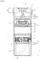
- FIG. 1 is a cross-sectional view showing a portable air purifier 1 of a first embodiment
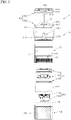
- FIG. 2 is a cross-sectional view separately showing the portable air purifier 1 of the first embodiment
- FIG. 3 is a perspective view separately showing the portable air purifier 1 of the first embodiment.
- the portable air purifier 1 of the first embodiment may have an approximately cylindrical shape.
- the portable air purifier 1 may include at least one of a housing 10, a filter part 40, a fan module 70, a discharge part 140, a sterilizer 200 and a rotation supporter 300.
- the housing 10 may be provided with an entrance part 22, and provided therein with the filter part 40, the sterilizer 200 and the fan module 70.
- the housing 10 may form an air flow path in an up-down direction. Since the air flow path having a cylindrical shape is formed inside the housing 10, frictional resistance of air moving in the up-down direction may decrease.
- centers of the entrance part 22, the filter part 40, the sterilizer 200, the fan module 70, the rotation supporter 300 and an outlet 24 may be aligned in the up-down direction along a rotation axis extending line E that passes through the center of the housing 10 in the up-down direction. Accordingly, air moving along the housing 10 from a lower side to an upper side may flow linearly in a perpendicular direction, resulting in a decrease in the length of the flow path of the air, and flow resistance of the air may decrease, thereby improving air purification efficiency.
- the rotation axis extending line E may be the same as a rotation center of a fan member included in the fan module 70, and may be aligned with a perpendicular reference line that passes through the center of the hosing 10 and extends in the up-down direction.
- the perpendicular reference line When the portable air purifier 1 is placed on a horizontal surface, the perpendicular reference line may be aligned with a perpendicular line or the rotation axis extending line E.
- the housing 10 may be comprised of a single member, or a plurality of members, for example.
- the portable air purifier 1 may be entirely formed into a cylinder that is elongated in the up-down direction and stands. Accordingly, a user may use the portable air purifier 1 in a state where the portable air purifier 1 lies or stands. Further, the portable air purifier 1 may be used in a state where the portable air purifier 1 is installed in a groove part such as a cup holder that is concave downward, in a place such as a rocking vehicle. Thus, the portable air purifier 1 may be reliably disposed in its place.
- Directions are defined as follows. Under the assumption that a portion in a direction where the discharge part 140 is disposed with respect to the first case 20 is defined as an upper portion, and a portion in a direction where a second case 30 is disposed with respect to the first case 20 is defined as a lower portion, a "first direction" denotes an up-down direction or an axial direction. The first direction may be referred to as a perpendicular direction. Additionally, a "second direction” denotes a direction perpendicular to the first direction, i.e., a left-right direction, a horizontal direction or a radial direction.
- the portable air purifier 1 of this embodiment may include a housing 10, a filter part 40, a fan module 70 and a sterilizer 200.
- the portable air purifier 1 may further include a discharge part 140 and a battery 290.
- the housing 10 may include a first case 20 and a second case 30.
- the first case 20 and the second case 30 may form a skeleton of the exterior of the portable air purifier 1. Exteriors of lateral and bottom surfaces of the portable air purifier 1 may be formed by the first case 20 and the second case 30.
- the first case 20 and the second case 30 may be provided therein with an accommodation space 21.
- the accommodation space 21 may accommodate the filter part 40, the fan module 70, the sterilizer 200, the rotation supporter 300, electronic components including the battery 290, and the like.
- the first case 20 and the second case 30 may have enough strength to protect the accommodated components from an external impact, for example.
- the filter part 40 may be installed in the accommodation space 21 of the first case 20 and disposed between the fan module 70 and the entrance part 22. That is, the filter part 40 may be disposed under/below the fan module 70 and may purify air suctioned through the entrance part 22 of the portable air purifier 1. The air, which is purified while passing through the filter part 40, may pass through the fan module 70 and the discharge part 140 and may be discharged from an upper portion of the portable air purifier 1.
- the filter part 40 disposed on an upper side of the entrance part 22 and configured to purify air suctioned into the entrance part 22 and moving upward, may be installed inside the first case 20 to face the entrance part 22.
- the filter part 40 may be formed into a cylinder that is elongated in the up-down direction.
- a predetermined distance may be set between an upper end of the entrance part 22 and a lower end of the filter part 40. The distance may be determined considering an incident angle and an irradiation distance of a light ray for sterilization irradiated from an irradiator 280. Additionally, the distance may also be determined considering reflectivity and performance of a reflector 230.
- the filter part 40 may be comprised of a single filter, or when necessary, may be comprised of a plurality of filters in a state of being stacked.
- the filter part 40 may be further provided with a filter case (not illustrated) for fixing a filter.
- the filter case may be fixed to an inside of the first case 20 and may be provided therein with an insertion space for accommodating a filter.
- the fan module 70 may be accommodated in the accommodation space 21 of the first case 20 and disposed between the discharge part 140 and the filter part 40. Specifically, the fan module 70 may be disposed between the outlet 24 and the filter part 40. That is, the fan module 70 may be disposed on/over the filter part 40, and the outlet 24, the rotation supporter 300, the discharge part 140 and a rotation guide 400 may be disposed on/over the fan module 70.
- the fan module 70 may suction air introduced into a lower portion of the filter part 40 through the entrance part 22 and discharge the air from the upper portion of the first case 20.
- a rotation center of the discharge part 140 may be aligned with the center of the fan module 70 in the up-down direction.
- the air suctioned through the entrance part 22 may pass through the filter part 40, the fan module 70, a guide vane 356 and the discharge part 140 consecutively while moving upward, and may be discharged from an upper side of the portable air purifier 1.
- the fan module 70 includes a mixed flow fan, for example.
- the fan module 70 may suction the air having passed through the filter part 40 in the axial direction and discharge the air in a direction between the axial direction and the radial direction.
- the discharge part 140 may be rotatably disposed on an upper side of the first case 20 and may guide a discharge direction of air moved upward through the outlet 24.
- the rotation supporter 300 may be disposed on/over the first case 20, and the discharge part 140 may be rotatably disposed at/mounted onto the rotation supporter 300.
- the discharge part 140 may have upper and lower sides that are both open, and air moved to a lower portion of the discharge part 140 through the rotation supporter may be discharge out of the portable air purifier 1 through an upper portion of the discharge part 140.
- the sterilizer 200 may be disposed under/below the filter part 40 and fixed to at least one of the first case 20 and the second case 30.
- the sterilizer 200 may be spaced a predetermined distance apart from the filter part 40, and irradiate a light ray for sterilization toward the filter part 40.
- the light ray for sterilization irradiated by the sterilizer 200 is harmful to the human body. Accordingly, a position of the sterilizer 200 may be determined such that the light ray for sterilization does not leak out of the portable air purifier 1 through the entrance part 22.
- the sterilizer 200 may be disposed on an inner side of the housing 10, facing the entrance part 22, an exterior of the housing 10 may not be scaled up despite installation of the sterilizer 200, thereby making it possible to provide a compact-sized portable air purifier 1 and sterilize the filter part 40.
- the battery 290 may be installed in the accommodation space 21 provided inside the second case 30 and disposed under/below the sterilizer 200.
- the battery 290 may supply power for driving the portable air purifier 1.
- the accommodation space 21 provided in the portable air purifier 1 may be divided into a first area A and a second area B.
- an upper area may be the first area A
- a lower area may be the second area B.
- the first area A and the second area B may be conceptually divided areas rather than physically divided areas.
- the accommodation space 21 in the first case 20 and the accommodation space 21 in the second case 30, which form the skeleton of the portable air purifier 1, may be the first area A and the second area B respectively.
- Components in relation to the suction, purification, discharge and sterilization of air may be disposed in the first area A. That is, the entrance part 22, the filter part 40, the fan module 70, the rotation supporter 300, the discharge part 140 and the sterilizer 200 for sterilizing the filter part 40 may be disposed in the first area A. Accordingly, in the first area A, air may flow from the lower side to the upper side, and a discharge direction of air may be adjusted through the discharge part 140 that is rotatably installed.
- the entrance part 22 may be installed in the first case 20, and the entrance part 22 may be provided with a plurality of entrance holes 23 as a passage for suctioning air.
- the outlet 24 as a passage for discharging air purified in the first area A, and the discharge part 140 rotatably disposed at/mounted onto the rotation supporter 300 may be disposed on/over the first case 20. Accordingly, the first case 20 may be provided therein with an air flow path connecting the filter part 40, the fan module 70 and the discharge part 140.
- the sterilizer 200 may be disposed in an inner space of the housing 10, facing the entrance part 22. Accordingly, the housing 10 may not be scaled up to install the sterilizer 200, and space availability may improve.
- the entrance part 22, the filter part 40, the fan module 70, the discharge part 140, the sterilizer 200, and the outlet 24 may be installed in the first area A.
- a passage for allowing air, suctioned into the portable air purifier 1, to pass through the air purifier may be formed in the first area A.
- Components that do not directly relate to a flow of air for air purification may be disposed in the second area B. That is, a controller including a PCB, the battery 290 and the like may be installed in the second area B.
- the housing 10 may be formed into a cylinder that has a vertical length greater than a lateral length.
- the first area A in the upper portion may have a vertical length greater than a vertical length of the second area B in the lower portion. That is, in the portable air purifier 1 that stands vertically, the first area A in the upper portion may be greater than the second area B in the lower portion.
- the discharge part 140 may be rotatably disposed at/mounted onto the rotation supporter 300. Accordingly, a discharge direction of air purified in the upper portion of the portable air purifier 1 may be readily adjusted, and air purified in the portable air purifier 1 may reach the face of the user more readily.
- the portable air purifier 1 When the portable air purifier 1 is placed and used on a bottom surface placed further downward than the face of the user, the portable air purifier 1 may stand vertically rather than lie transversely to allow more air, purified in the portable air purifier 1, to reach the face of the user.
- the sterilizing and supporting part 210 is arranged along a perimeter of the irradiator 280, a light ray for sterilization aiming at the filter part 40 may be blocked from being irradiated out of the housing 10 through the entrance part 22.
- the irradiator 280 may be provided with a reflector 230 around an outer perimeter thereof, and a light ray for sterilization irradiated from the irradiator 280 to the filter part 40 may be prevented from being irradiated out of the entrance part 22 and may be guided and irradiated to a lower side of the filter part 40 by the reflector 230.
- a portable air purifier 1 of the first embodiment may include at least one of a housing 10, a filter part 40, a fan module 70, a discharge part 140, and a sterilizer 200.
- the portable air purifier 1 in the first embodiment may further include a rotation supporter 300 and a battery 290.
- the housing 10 may include a first case 20 and a second case 30.
- the first case 20 may be provided with an accommodation space 21 therein and an entrance part 22 for suctioning air on a lateral surface of a lower portion thereof.
- the first case 20 may be formed into a cylinder and have upper and lower sides that are open.
- the first case 20 may be comprised of a single component, or when necessary, may be comprised of a plurality of members.
- a first case 20 in the first embodiment is comprised of a plurality of members, and each member may be fitted-coupled, coupled using an adhesive or welded and may be coupled in various ways such as a connection using a fastening member 195 including a bolt and the like.
- Air may be suctioned through the lateral surface of the lower portion of the first case 20 and discharged through an upper side of the first case 20.
- the entrance part 22 provided with entrance holes 23 may be disposed along a perimeter of a lower portion of the first case 20.
- the first case 20 may be provided with an outlet 24 for discharging air, on the upper side thereof.
- a filter part 40 may be disposed on an upper side in a way that the filter part 40 is spaced from the entrance part 22. Accordingly, air may move uniformly across an entire surface of the filter part 40.
- the entrance part 22 may be provided with a plurality of entrance holes 23.
- the entrance hole 23 may be disposed at a slant in an oblique line shape, and when necessary, formed into an inequality sign.
- the entrance hole 23 may be modified in various ways. For example, to increase a flow rate of air flowing into the filter part 40, the entrance hole 23 may be additionally formed on a lateral surface of the housing 10, on which the filter part 40 is disposed.
- the housing 10 may be modified in various ways.
- the hosing 10 may be comprised of three or more members.
- the second case 30 may connect to the lower portion of the first case 20, and may be modified in various ways within the technical scope in which the second case is provided therein with a space in which electronic components including a battery 290 is installed.
- At least one of the first case 20 and the second case 30 may be formed into a cylindrical case.
- the first case 20 and the second case 30 may both be formed into a cylinder or the second case 30 may only be formed into a cylinder.
- the first case 20 may only be formed into a cylinder.
- the user may readily hold an outer perimeter of the second case 30 in the hand, and the second case 30 may be easily held in a vehicle's cup holder provided with a groove part ordinarily having a circular cross section.
- an air flow path may be formed inside the first case 20, and no air flow path may be formed inside the second case 30. Accordingly, air may be smoothly suctioned and discharged through the first case 20 even when the second case 30 is held in the cup holder or the user's hand, thereby ensuring improvement in usability and convenience.
- the inner housing 35 for supporting a sterilizer 200 may be disposed on the second case 30.
- the inner housing 35 may be formed into a plate and may support a lower portion of the sterilizer 200.
- An inner housing 35 in the first embodiment may be formed into a circular plate, and may shield an upper side of the second case 30.
- the inner housing 35 may be fixed to at least one of the first case 20 and the second case 30 and provided with a hole for fixing a support bracket 270 of the sterilizer 200.
- the inner housing 35 may be disposed between the first case 20 and the second case 30 and may shield the lower portion of the first case 20. Additionally, the inner housing 35 may be disposed on a lower side of the sterilizer 200, and may be modified in various ways within the technical scope in which the inner housing connects to the housing 10 and movement of the inner housing is restricted.
- Air suctioned into the first case 20 through the entrance part 22 may be blocked from moving to the second case 30 by the inner housing 35 such that a flow rate of air moving to the fan module 70 increases, thereby ensuring improvement in air purification performance of the portable air purifier 1.
- the filter part 40 may be disposed inside the first case 20 and may be modified in various ways within the technical scope in which the filter part purifies air suctioned into the entrance part 22.
- a filter part 40 in the first embodiment maybe formed into a cylinder.
- the first case 20 may be formed into a circular pipe, and the filter part 40 installed in the first case 20 may be formed into a cylinder in contact with the inside of the first case 20. Accordingly, impurities in air passing through the first case 20 may be removed effectively.
- a transverse cross section of the filter part 40 may have a circular shape, the filter part 40 may have the largest area in the first case 20. Additionally, the filter part 40 may be formed into a cylinder, and when upper and lower ends of cloth of the filter part 40 are cut, pressure loss may be minimized, and performance of the filter part 40 may be maximized.
- An outer diameter of the filter part 40 may be greater than a diameter of an entrance through which air is suctioned into the fan module 70. Accordingly, volume of the filter part 40 may be maximized.
- the filter part 40, the fan module 70, the sterilizer 200, the discharge part 140 may be disposed along the housing 10 in the up-down direction, and air may also flow in the up-down direction. That is, air may flow linearly in a direction the same as the direction in which the filter part 40, the fan module 70 and the discharge part 140 are disposed, as a result of operation of the fan module 70.
- An antimicrobial HEPA filter may be used as a filter part 40 in the first embodiment.
- an irradiator 280 may not operate, and the filter part 40 may not be sterilized correctly.
- a HEPA filter to which an antimicrobial agent is applied may be used as the filter part 40.
- the fan module 70 may be disposed between the filter part 40 and the outlet 24, and may be modified in various ways within the technical scope in which the fan module rotates a fan to blow air toward the outlet 24.
- the first case 20 may not be scaled-up despite fixation or a coupling of the fan module 70 since the shape of the fan module 70 matches or corresponds to the cylindrical shape of the inside of the first case 20, thereby making a product smaller.
- the portable air purifier 1 according to the present disclosure when applied to a vehicle, the portable air purifier 1 may be small enough to fit into a cup holder.
- a fan of the fan module 70 may be comprised of a mixed flow fan, and an inner structure of the fan module 70 may change to mount the mixed flow fan.
- a fan member 90 according to the disclosure may rotate as a result of operation of a motor.
- a rotation shaft of the motor configured to rotate the fan member 90 may only connect to the fan member 90.
- a rotor may be installed in the fan member 90, and a stator may be installed in the fan housing 80 the rotation of which is restricted. Since a magnetic field of the stator changes, the shaft connected to the fan member 90 may rotate along with the rotor such that the rotor and the fan member 90 rotate around the stator.
- the configuration of the motor for rotating the fan member 90 is well known. Thus, detailed description in relation to this is omitted.
- a fan module 70 in the first embodiment may include a fan housing 80, a fan member 90, and a fan base 130.
- the fan housing 80 may be fixed to the inside of the first case 20, and may be modified in various ways within the technical scope in which the fan housing is provided therein with a space for rotating the fan member 90.
- the fan member 90 may be rotatably installed in the fan housing 80, and may be modified in various ways within the technical scope in which the fan member moves air toward the discharge part 140.
- a mixed flow fan may be used as the fan member 90 but not limited.
- Another type of fan may also be used as the fan member 90 according to the disclosure.
- the fan base 130 may be coupled to a lower side of the fan housing 80, and may be modified in various ways within the technical scope in which the fan base guides air having passed through the filter part 40 into the fan member 90.
- the fan base 130 may be disposed between the filter part 40 and the fan member 90.
- An edge of the fan base 130 may have a shape corresponding to a shape of an edge of the filter part 40.
- the fan base 130 may be formed into a ring provided with a hollow hole/may be installed in a ring shape provided with a hollow hole.
- the discharge part 140 may be rotatably disposed at/mounted onto a rotation supporter 300, and may be modified in various ways within the technical scope in which the discharge part adjusts a discharge direction of air having passed through the fan module 70.
- the discharge part 140 according to the disclosure may be rotatably disposed at/mounted onto a sphere-shaped ball joint 370 installed in the rotation supporter 300 and may rotate smoothly.
- the discharge part 140 may be open in the up-down direction and may rotatably connect to the rotation supporter 300. Accordingly, the discharge part 140 may adjust a discharge direction of air having passed through the fan module 70.
- a discharge part 140 in the first embodiment may include a first discharge part 150 and a second discharge part 160.
- the first discharge part 150 may be disposed on one side of the ball joint 370 (an upper side in FIG. 2 ), and may be modified in various ways within the technical scope in which the first discharge part is provided with a plurality of vanes 156 configured to guide discharge of air.
- a first discharge part 150 in the first embodiment may include a first discharge core 152, a first discharge body 154, and a vane 156.
- the first discharge core 152 may surround an upper side of the sphere shape of the ball joint 370 and may be disposed on an upper side of a core member 310. Additionally, the first discharge body 154 may surround an outside of the first discharge core 152 in a ring shape, and an outside of the first discharge body 154 may be formed into a curved surface.
- first discharge core 152 and the first discharge body 154 may be connected by a plurality of vanes 156, the first discharge core 152, the first discharge body 154 and the vanes 156 may rotate together.
- the second discharge part 160 may be disposed on the other side of the ball joint 370 (a lower side in FIG. 2 ) and connected to the first discharge part 150, and may be modified in various ways within the technical scope in which the second discharge part rotates around the ball joint 370 together with the first discharge part 150.
- a second discharge part 160 in the first embodiment may include a second discharge core 161, a second discharge body 162, and a discharging and supporting part 163.
- the second discharge core 161 may surround a lower side of the sphere shape of the ball joint 370 and may be disposed on a lower side of the first discharge core 152. Additionally, the second discharge body 162 may surround an outside of the second discharge core 161 in a ring shape, and an outside of the second discharge body 162 may be formed into a curved surface.
- the second discharge core 161 and the second discharge body 162 may be connected by a plurality of discharging and supporting parts 163, the second discharge core 161, the second discharge body 162, and the discharging and supporting parts 163 may rotate together.
- the rotation supporter 300 may be modified in various ways within the technical scope in which the rotation supporter rotatably supports the discharge part 140 disposed in the outlet 24 of the housing 10.
- a rotation supporter 300 in the first embodiment may include a core member 310, a core supporter 350 and a ball joint 370.
- the core member 310 may be disposed on a lower side of the discharge part 140 and extended toward the discharge part 140.
- the core member 310 may be disposed on the lower side of the discharge part 140 configured to adjust a discharge direction of air and extended from a center of the outlet 24 toward the discharge part 140.
- An outside of the core member 310 may be formed into a curved surface, and a transverse cross section of the core member 310 may gradually become narrow from a lower side of the core member 310, connected to the core supporter 350, toward the ball joint 370. Accordingly, resistance of air moving from the lower side of ... to the upper side thereof may be minimized.
- the outside of the core member 310 may be formed into a curved surface, and may be modified in various ways.
- a transverse cross section of the core member remains constant or changes from the lower side of the core member, connected to the core supporter 350, toward the ball joint 370.
- the core member 310 may have a circular cone shape, and the transverse cross section of the core member may gradually decrease further toward the upper side of the core member.
- the core supporter 350 may be modified in various ways within the technical scope in which the core supporter supports a lower portion of the core member 310 and is fixed to the housing 10.
- a vane disposed at/installed in the core supporter 350 may be modified in various ways.
- the vane may be extended radially or installed in a spiral shape with respect to the core member 310.
- the ball joint 370 may be modified in various ways within the technical scope in which a lower side of the ball joint is coupled to the core member 310 such that movement of the ball joint 370 is restricted, and an upper side of the ball joint is inserted into the discharge part 140 and rotatably supports the discharge part 140.
- the ball joint 370 may have a sphere-shaped end, may be disposed inside the discharge part 140 and may rotatably support the discharge part 140.
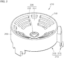
- FIG. 7 is a cut-away perspective view partially showing the sterilizing and supporting part 210 in the first embodiment
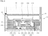
- FIG. 8 is a view showing the sterilizer 200 in the first embodiment disposed on a lower side of a filter part 40.
- the sterilizer 200 may be disposed on a lower side of the filter part 40 and disposed at the same height as that of the entrance part 22. Since the sterilizer 200 and the entrance part 22 are disposed at the same height, the air purifier according to the present disclosure may ensure improvement in space availability unlike an air purifier in which a sterilizer 200 is disposed on an upper side of an entrance part 22, and the housing 10 according to the disclosure may be disposed at a low position unlike a housing 10 of the air purifier in which the sterilizer 200 is disposed on the upper side of the entrance part 22.
- the sterilizer 200 may be modified in various ways within the technical scope in which the sterilizer irradiates a light ray for sterilization to sterilize the filter part 40.
- the sterilize 200 in the first embodiment may include a sterilizing and supporting part 210 and an irradiator 280.
- the sterilizing and supporting part 210 may be fixed to the housing 10 while supporting the irradiator 280.
- the sterilizing and supporting part 210 may be modified in various ways within the technical scope in which the sterilizing and supporting part is disposed around an outer perimeter of the irradiator 280.
- the sterilizing and supporting part 210 in the first embodiment may be fixed to at least one of the first case 20 and the second case 30.
- the sterilizing and supporting part 210 may include a support body 220 and a support bracket 270.
- the support body 220 may be disposed around the outer perimeter of the irradiator 280, and may be modified in various ways within the technical scope in which the support body reflects a light ray for sterilization irradiated from a sterilizing light source 282 to the filter part 40.
- a support body 220 in the first embodiment may include at least one of a reflector 230, an inner supporter 240, a heat dissipating hole part 250 and a blocking body 260.
- the reflector 230 may be concave toward the filter part 40 and provided with the sterilizing light source 282 of the irradiator 280 at a center thereof.
- the reflector 230 may reflect light irradiated from the sterilizing light source 282 of the irradiator 280 toward the filter part 40.
- the reflector 230 may be disposed on an inner side of the housing 10, facing the entrance part 22. Since ultraviolet rays used as the sterilizing light source 282 are harmful to the human body, the support body 220 including the reflector 230 may be installed to prevent a light ray for sterilization from being irradiator out of the housing 10. The reflector 230 may be installed to block a light ray for sterilization from being irradiated to the housing 10, which is an injection mold, except for the filter part 40, or from leaking out of the housing 10 through the entrance part 22. The reflector 230 may be designed considering an incident angle of a light ray for sterilization and a surface area of the filter part 40.
- the reflector 230 may be formed into a funnel, an upper side of which is open, and an upper end of the reflector 230 may be disposed on the same line as an upper end of the entrance part 22 or disposed higher than the upper end of the entrance part 22. Accordingly, a light ray for sterilization irradiated from the sterilizing light source 282 may be prevented from being irradiated out of the entrance part 22.
- an angle of the reflector 230 may be designed not to limit a light ray for sterilization toward an edge of the filter part 40.
- a reflector 230 in the first embodiment may include a first reflecting body 232 and a second reflecting body 234.
- the first reflecting body 232 may be disposed along a perimeter of the sterilizing light source 282 and spaced a predetermined distance D apart from the sterilizing light source 282.
- the second reflecting body 234 may extend upward from the first reflecting body 232 at a slant.
- a second reflecting body 234 in the first embodiment may be formed into a funnel an upper side of which is open, and an inner diameter of the second reflecting body 234 may gradually increase from the first reflecting body 232 toward the filter part 40.
- a reflecting and coating layer may be formed on a surface of the reflector 230.
- the surface of the reflector 230 which is an injection mold may be coated with a material such as aluminum, chrome and the like having high reflectivity such that the reflector 230 serves as a reflecting plate.
- the first reflecting body 232 facing the sterilizing light source 282 may only be provided with a coating layer.
- the second reflecting body 234 may also be provided with a coating layer.
- reflectivity may be 90 %.
- the reflecting surface of the first reflecting body 232, facing the sterilizing light source 282, may be installed while forming a predetermined angle F with a horizontal line.
- a predetermined angle F of a reflecting surface in the first embodiment may be a slant angle of 805 degrees. Accordingly, a light ray for sterilization irradiated from the sterilizing light source 282 may be directly irradiated to the edge of the filter part 40, or may reflect off the first reflecting body 232 and then be irradiated to the edge of the filter part 40, thereby minimizing loss of the light ray for sterilization. Since the reflector 230 is installed as describe above, an average illumination may improve to 6%, and a minimum illumination may improve to 26% with respect to UVC-LED 10mW.
- a predetermined distance D between a sterilizing light source 282 and a first reflecting body 232 in the first embodiment may be 1.4 mm to 5 mm.
- a distance between the sterilizing light source 282 and the filter part 40 is referred to as a first length G1 and that a radius of a lower surface of the filter part 40 is referred to as a second length G2.
- a second length G2 in the first embodiment may be 1.8 to 2.2 times greater than a first length G1.
- the inner supporter 240 may be modified in various ways within the technical scope in which the inner supporter extends to a lower side of the reflector 230 and supports the printed circuit board 281 of the irradiator 280.
- An inner supporter 240 in the first embodiment may include an inner bracket 242 extended to the lower side of the reflector 230, and a held hook 244 bent inward from a lower side of the inner bracket 242 to the irradiator 282 and held at an edge of the irradiator 280.
- a plurality of inner supporters 240 may be provided and extended to the lower side of the reflector 230.
- the inner supporter 240 may operate like a hook, and may be held at an outer edge of the printed circuit board 281. Accordingly, the printed circuit board 281 may be fixed to an inside of the support body 220.
- the heat dissipating hole part 250 may form a plurality of holes at the reflector 230. Since air moves through the heat dissipating hole part 250, the heat dissipating hole part 250 may air-cool the irradiator 280.
- the heat dissipating hole part 250 may be provided with a plurality of long holes having a circular arc shape around the sterilizing light source 282. In the heat dissipating hole part 250, a slit hole extended in a circular arc form may be disposed around the sterilizing light source 282.
- the printed circuit board 281 of the irradiator 280 disposed on a lower side of the irradiator 280 may be air-cooled, thereby improving heat dissipation performance of the sterilizing light source 282 using a UVC LED.
- the blocking body 260 may extend from an outer edge of the reflector 230 to the lower side thereof.
- the blocking body 260 may be formed into a cylinder a lower side of which is open, and centers of the blocking body 260 and the entrance part 22 may be aligned with each other. Since the blocking body 260 is provided, the blocking body 260 may block movement of the sterilizing light source 282 although the sterilizing light source 282 is irradiated from the irradiator 280 to the lower side of the reflector 230.
- the reflector 230 may block the light ray for sterilization primarily, and the blocking body 260 may block the light ray for sterilization secondarily.
- the support bracket 270 may be modified in various ways within the technical scope in which the support bracket extends to a lower side of the support body 220 and is fixed to the housing 10.
- the support bracket 270 may extend to the lower side of the support body 220 and may be fixed to at least one of the first case 20 and the second case 30 or may be fixed to the inner housing 35 shielding the upper side of the second case 30.
- a support bracket 270 in the first embodiment may be coupled to the inner housing 35 having a plate shape in a hook form. Accordingly, the sterilizer 200 may be installed and disassembled easily, and time and costs spent for maintenance and repairs of the sterilizer 200 may decrease.
- the irradiator 280 may be disposed on the lower side of the filter part 40 and disposed at a height where the irradiator 280 overlaps the entrance part 22, and may irradiate a light ray for sterilization to the filter part 40. Additionally, movement of the irradiator 280 may be restricted by the sterilizing and supporting part 210 and may be on a perpendicular reference line that passes through a radius-wise center of the entrance part 22 in the up-down direction. The perpendicular reference line and the rotation axis extending line may form the same straight line. Further, the centers of the first case 20, the filter part 40, the fan module 70 and the irradiator 280 may be aligned in the up-down direction.
- a sterilizing light source 282 supplying a relatively small amount of light may sterilize an entire surface area of the lower end of the filter part 40, thereby reducing costs incurred for manufacturing, maintenance and repairs.
- the irradiator 280 may be modified in various ways within the technical scope in which the irradiator is disposed at a position higher than or the same as that of the upper end of the entrance part 22.
- An irradiator 280 in the first embodiment may include a printed circuit board 281 and a sterilizing light source 282.
- the printed circuit board 281 may be fixed to an inside of the sterilizing and supporting part 210, and the sterilizing light source 282 configured to irradiate a light ray for sterilization may be disposed on an upper side of the printed circuit board 281 or inside the printed circuit board 281.
- the printed circuit board 281 may be held by the inner supporter 240 included in the support body 220 such that movement of the printed circuit board 281 is restricted.
- the sterilizing light source 282 disposed on the printed circuit board 281 may be disposed on the lower side of the filter part 40 and may irradiate a light ray for sterilization at an incident angle set to face an upper side on which the filter part 40 is disposed. Since radius-wise centers of the sterilizing light source 282 and the filter part 40 are aligned in the up-down direction, a light ray for sterilization may be uniformly irradiated to a lower portion of the filter part 40.
- the sterilizing light source 282 may be a UVC LED, and a variety of sterilizing devices may be used within the technical scope in which the sterilizing light source sterilizes germs in the filter part 40.
- the reflector 230 is disposed along the perimeter of the sterilizing light source 282 although the sterilizing light source 282 of the sterilizer 200 and the entrance part 22 are disposed at the same height, a light ray for sterilization may be prevented from being irradiated out of the first case 20 through the entrance part 22.
- an incident angle of the UVC LED configured to irradiate a light ray for sterilization is limited. Accordingly, when a proper distance between the filter part 40 and the UVC LED is not ensured, the edge of the filter part 40 may not be sterilized by the UVC LED.
- a light ray for sterilization may be uniformly irradiated to the lower portion of the filter part 40, thereby ensuring improvement in sterilization performance.
- the reflector 230 may be disposed around the outer perimeter of the irradiator 280 and formed into a funnel, the reflector 230 may reflect a light ray for sterilization to the filter part 40.
- reflectivity increases thanks to the reflective coating of the reflector 230, an incident angle and an irradiation distance of a light ray for sterilization may be ensured even in a limited space.
- the entrance part 22 for suctioning external air may be disposed around the outer perimeter of the first case 20. Accordingly, air outside the first case 20 may move into the first case 20 through the entrance part 22 such that a flow rate of suctioned air increases.
- air outside the portable air purifier 1 may flow into the portable air purifier 1.
- the air outside the portable air purifier 1 may form a spiral-shaped air flow rotating around an outer perimeter of the inner supporter 240 while passing through the entrance holes 23.
- the air which flows into the first case 20 and moves upward while rotating in a spiral shape, may move up toward the filter part 40, rotating a perimeter of the sterilizer 200. Additionally, the air having passed through the filter part 40 may move to an upper side of the housing 10 through the fan module 70.
- the filter part 40, the fan module 70 and the rotation supporter 300 are disposed on one straight line in the up-down direction, flow loss may be minimized and air may be effectively suctioned and filtered.
- Air suctioned into the fan module 70 may be discharged from an upper side of the fan module 70 and may move into the discharge part 140. Since the discharge part 140 rotates within predetermined angles, a direction of discharged air may be adjusted depending on an angle at which the discharge part 140 is installed.
- an inside of the discharge part 140 may form a concave groove part. Accordingly, discharge resistance of air, the direction of which is changed through the discharge part 140, may decrease. Further, since the filter part 40, the fan module 70 and the discharge part 140 are disposed on one straight line in the up-down direction, flow loss of air may be minimized, air may be effectively suctioned and filtered, and purified air may be effectively discharged.
- Germs in the air may be collected in the filter part 40, and a light ray for sterilization irradiated from the sterilizing light source 282 may be irradiated to the lower portion of the filter part 40, A light ray for sterilization may be directly irradiated to the filter part 40 or may reflect off the reflector 230 and then be irradiated to the lower portion of the filter part 40 to sterilize the filter part 40.
- the sterilizing light source 282 may use a light ray having a wavelength of 275 nm that shows high sterilization efficiency as a light ray for sterilization, and considering a UV radiation range on the surface of the filter part 40 using a HEPA filter and reliability of a filter, the first length G1 as an irradiation distance may be set to 17.7 mm or so.
- sterilization performance may improve, but after the filter part 40 is used for a long time, degradation of the filter part 40 may cause damage to an exterior of the filter part 40 or particle removal performance of the filter part 40 may deteriorate. Additionally, when an optimal distance between the filter part 40 and the sterilizing light source 282 is not maintained, an amount of light reaching the edge of the filter part 40 may decrease, and sterilization performance may deteriorate. With the sterilizer 200 according to the present disclosure, surface illumination may be ensured even for the edge of the filter part 40, and reliability of the filter part 40 may be ensured.
- a portable air purifier 1 provided with the sterilizer 200 When a portable air purifier 1 provided with the sterilizer 200 is installed in a vehicle, germs and viruses in the vehicle may be attached to the filter part 40 and then a light ray for sterilization may be irradiated to eliminate the germs attached to the filter part 40.
- Bacteria and viruses in polluted air suctioned into an inlet of a vehicle may be collected using an electrostatic force of the filter part 40 using a HEPA filter. Then a light ray for sterilization may be irradiated to eliminate the bacteria and viruses collected in the filter part 40.
- FIG. 9 is a cross-sectional view showing a sterilizer 400 of a second embodiment
- FIG. 10 is a perspective view showing the sterilizer 400 of the second embodiment
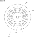
- FIG. 11 is a plan view showing the sterilizer 400 of the second embodiment.
- the sterilizer 400 of the second embodiment may include a sterilizing and supporting part 410 and an irradiator 480.
- the sterilizing and supporting part 410 may support a lower portion of the irradiator 480, may be disposed on an inner side of a housing 10, facing an entrance part 22, and may include a support body 420 and a support part 470.
- a support body 420 in the second embodiment may include a reflector 230, a heat dissipating hole part 450, and a blocking body 460.
- the reflector 430 may be formed into a funnel an upper side of which is open, and may be provided with the radiator 480 configured to irradiate a light ray for sterilization at a concave center thereof.
- the heat dissipating hole parts 450 may air-cool the irradiator 480 fixed to the support body 420.
- the reflector 430 may be provided with the blocking body 460 having a pipe shape around an outer perimeter thereof.
- the support body 420 may be supported by the support part 470.
- the support part 470 may be modified in various ways within the technical scope in which the supporting part protrudes upward from a center of an inner housing 35 and supports a lower portion of the support body 420.
- the support part 470 may be disposed at a center of the entrance part 22 in a radial direction thereof, and a transverse cross section of the support part 470 may have a circular shape to reduce friction between the support part 470 and air.
- the support part 470 may be formed into a pillar that protrudes upward from the center of the inner housing 35.
- the support part 470 may be formed into a cylinder or a circular cone.
- a support part 470 in the second embodiment may have a transverse cross section that gradually becomes narrow from a lower side to an upper side, and since the support part 470 is disposed at a center of a first case 20, where the entrance part 22 is formed, friction between the support part 470 and air may be minimized.
- the transverse cross section of the support part 470 may have a circular shape, and air suctioned through the entrance part 22 may move to an upper side on which a filter part 40 is disposed while rotating an outside of the support part 470. That is, the sterilizer 400 may be disposed in a central portion of the first case 20, and air suctioned through the entrance part 22 may move up while rotating around an outer perimeter of the sterilizer 400. Accordingly, flow resistance of the sterilizer 400 may decrease.
- a radius-wise center of the support part 470, a rotation center of a fan member 90 and a radius-wise center of the filter part 40 may be on one straight line in the perpendicular direction. In this case, resistance against a flow of air moving from the lower side to the upper side may decrease, and air may flow more smoothly. Thus, the portable air purifier 1 may ensure improvement in air purification performance.
- FIG. 12 is a plan view showing a sterilizer 500 of a third embodiment.
- the sterilizer 500 of the third embodiment may include a sterilizing and supporting part 510 and an irradiator 560.
- the sterilizing and supporting part 510 may include a reflector 530 and a heat dissipating hole part 550, and the irradiator 560 configured to irradiate a light ray for sterilization may be disposed at a concave center of the reflector 530.
- the reflector 530 may be provided with a plurality of heat dissipating hole parts 550 forming a circular hole. Accordingly, the heat dissipating hole parts 550 may air-cool the irradiator 560 fixed to the sterilizing and supporting part 510.
- the heat dissipating hole part 550 may be formed into various shapes including a triangle, a polygon and the like, and may be modified in various ways within the technical scope in which the heat dissipating hole part air-cools the irradiator 560.
Landscapes
- Chemical & Material Sciences (AREA)
- Engineering & Computer Science (AREA)
- Chemical Kinetics & Catalysis (AREA)
- Combustion & Propulsion (AREA)
- Mechanical Engineering (AREA)
- General Engineering & Computer Science (AREA)
- Health & Medical Sciences (AREA)
- Life Sciences & Earth Sciences (AREA)
- Veterinary Medicine (AREA)
- Epidemiology (AREA)
- Physics & Mathematics (AREA)
- Animal Behavior & Ethology (AREA)
- General Health & Medical Sciences (AREA)
- Public Health (AREA)
- Thermal Sciences (AREA)
- Disinfection, Sterilisation Or Deodorisation Of Air (AREA)
- Structures Of Non-Positive Displacement Pumps (AREA)
- Apparatus For Disinfection Or Sterilisation (AREA)
- Respiratory Apparatuses And Protective Means (AREA)
- Sampling And Sample Adjustment (AREA)
- Filtering Of Dispersed Particles In Gases (AREA)
Abstract
Description
- Disclosed herein is a portable air purifier, and more specifically, a portable air purifier that uses a light ray for sterilization to sterilize a filter part.
- Air purifiers are devices that are widely used in our daily lives. The devices can filter physical particles such as dust, fine dust, ultra fine dust and the like, chemical substances such as odorant particles, harmful gases and the like, and microorganisms such as germs, viruses and the like, to purify air.
- People cannot live without air purifiers in an industrial society since more and more people are greatly affected by fine dust and suffer from allergies. Accordingly, there is a growing demand for the devices. Additionally, as living standards improve, the demand for the air purifiers grows.
- Ordinarily, a large-sized air purifier is used in a house that is 100 square meters or greater. The air purifier can be provided with a filter for physical particles such as dust and the like, a filter for chemical substances such as gas and the like, and a filter for microorganisms such as germs, viruses and the like. That is, such a large-sized air purifier capable of accommodating various types of filters can be used in a large space.
- However, the large-sized air purifier is rarely used in a small space such as a studio apartment, a space in a vehicle and the like considering space availability, mobility and energy efficiency. Additionally, a user who moves from place to place usually uses a small-sized air purifier. Under the circumstances, there is a growing need for a portable air purifier that is easy to carry.
- The portable air purifiers need to be small and lightweight enough for users to carry such that the users easily carry and use the portable air purifiers anywhere. That is, the portable air purifiers are useful for people who often go out and move from place to place instead of staying in a place such as a house.
- In a prior art document (
KR Patent Publication No. 10-2020-0037187 - A portable air purifier has a limited size such that a user carries the portable air purifier readily. Accordingly, the portable air purifier is not provided with an additional sterilizer for sterilizing the filter inside a housing.
- Further, when a light ray for sterilization is used to sterilize the filter, part of the light ray for sterilization can leak out of the housing.
- Furthermore, when a light ray for sterilization is used to sterilize the filter, a proper incident angle and an irradiation distance of the light ray for sterilization cannot be properly ensured due to a limited size of the housing. As a result, the filter cannot be sterilized properly.
- A background art in relation to the subject matter of the present disclosure is disclosed in
KR Patent Publication No. 10-2020-0037187 (titled Portable Air Caring Apparatus and published on April 08, 2020 - The invention is specified by the independent claim. Preferred embodiments are defined in the dependent claims. The present disclosure is directed to a portable air purifier in which a sterilizer for sterilizing a filter part may be installed in a housing.
- The present disclosure is directed to a portable air purifier that may block a light ray for sterilization aiming at a filter part from being irradiated out of a housing.
- The present disclosure is directed to a portable air purifier in which an incident angle and an irradiation distance of a light ray for sterilization aiming at a filter part may be ensured despite a limited size of a housing.
- Aspects according to the present disclosure are not limited to the above ones, and other aspects and advantages that are not mentioned above can be clearly understood from the following description and can be more clearly understood from the embodiments set forth herein. Additionally, the aspects and advantages in the present disclosure can be realized via means and combinations thereof that are described in the appended claims.
- In a portable air purifier according to the present disclosure, a sterilizer may be disposed on a lower side of a filter part.
- Specifically, the sterilizer configured to irradiate a light ray for sterilization and sterilize the filter part may be disposed on the lower side of the filter part. Additionally, the sterilizer may be disposed on an inner side of the housing, facing an entrance part, and an exterior of the housing may not be scaled up despite the installation of the sterilizer, thereby making it possible to provide a compact-sized portable air purifier and sterilize the filter part.
- The portable air purifier according to the present disclosure may block a light ray for sterilization aiming at the filter part from being irradiated out of the housing.
- Specifically, a reflector may be disposed around an outer perimeter of an irradiator, and a light ray for sterilization irradiated from the irradiator to the filter part may be blocked from being irradiated out of the entrance part by the reflector.
- The portable air purifier according to the disclosure may ensure an incident angle and an irradiation distance of a light ray for sterilization aiming at the filter part despite a limited size of the housing.
- Specifically, the reflector disposed around the outer perimeter of the irradiator may have a funnel shape to reflect a light ray for sterilization to the filter part, and may include a reflective coating to increase reflectivity. Thus, a proper incident angle and irradiation distance of a light ray for sterilization may be ensured.
- A portable air purifier in one embodiment may include a housing provided with an entrance part forming a passage for suctioning air, a filter part disposed on an upper side of the entrance part and configured to purify air suctioned into the entrance part and moving upward, an irradiator disposed on a lower side of the filter part, installed at a height where the irradiator overlaps the entrance part and configured to irradiate a light ray for sterilization to the filter part, and a sterilizing and supporting part configured to support the irradiator, fixed to the housing and disposed around the outer perimeter of the irradiator.
- The irradiator may include a printed circuit board supported by the sterilizing and supporting part and disposed on the lower side of the filter part, and a sterilizing light source disposed on the printed circuit board and configured to irradiate a light ray for sterilization to the filter part.
- Additionally, centers of the sterilizing light source and the filter part may be aligned with each other in an up-down direction.
- The sterilizing and supporting part may include a support body disposed around the outer perimeter of the irradiator and configured to reflect a light ray for sterilization irradiated from the sterilizing light source to the filter part.
- The support body may include a reflector being concave toward the filter part, provided with the sterilizing light source at a center thereof, and configured to reflect light irradiated from the sterilizing light source to the filter part, and an inner supporter extended to a lower side of the reflector and configured to support the printed circuit board of the irradiator.
- The support body may further include a heat dissipating hole part forming a plurality of holes on the reflector and configured to air-cool the irradiator.
- The heat dissipating hole part may be provided with a plurality of long holes having a circular arc shape around the sterilizing light source.
- The reflector may be disposed on an inner side of the housing, facing the entrance part.
- The reflector may include a first reflecting body disposed around a perimeter of the sterilizing light source and spaced from the sterilizing light source, and a second reflecting body extended from the first reflecting body upward at a slant.
- The second reflecting body may be formed into a funnel an upper side of which is open, and may have an inner diameter that gradually increases from the first reflecting body toward the filter part.
- The inner supporter may include an inner bracket extended to the lower side of the reflector, and a held hook bent from a lower side of the inner bracket inward to the irradiator and held at an edge of the irradiator.
- The support body may further include a blocking body extended downward from an outer edge of the reflector.
- The blocking body may be formed into a cylinder a lower side of which is open, and a center of the blocking body and a center of the entrance part may be aligned with each other
- The sterilizing and supporting part may further include a support bracket extended to a lower side of the support body and fixed to the housing.
- A portable air purifier in one embodiment may include a first case provided therein with an accommodation space, provided with an entrance part for suctioning air on a lateral surface of a lower portion thereof and provided with an outlet for discharging air on an upper side thereof, a second case connected to the lower portion of the first case, a filter part installed inside the first case and configured to purify air suctioned into the entrance part, a fan module disposed between the filter part and the outlet and configured to rotate a fan to blow air toward the outlet, an irradiator disposed on a lower side of the filter part and configured to irradiate a light ray for sterilization to the filter part, and a sterilizing and supporting part configured to support the irradiator, fixed to at least one of the first case and the second case and disposed around an outer perimeter of the irradiator.
- Additionally, centers of the first case, the filter part, the fan module and the irradiator may be aligned with one another in an up-down direction.
- The sterilizing and supporting part may include a support body disposed around the outer perimeter of the irradiator and configured to reflect a light ray for sterilization irradiated from the irradiator to the filter part, and a support bracket extended to a lower side of the support body and fixed to at least one of the first case and the second case.
- The support body may include a reflector being concave toward the filter part, provided with the irradiator at a center thereof, and configured to reflect light irradiated from the irradiator to the filter part, and an inner supporter extended to a lower side of the reflector and configured to support a printed circuit board of the irradiator.
- The support body may further include a heat dissipating hole part forming a plurality of holes on the reflector and configured to air-cool the irradiator.
- Further, a reflective coating layer may be formed on a surface of the reflector.
- A portable air purifier according to the disclosure may prevent pollution of air since a filter part is sterilized by a light ray for sterilization irradiated from a sterilizer.
- The portable air purifier according to the disclosure may ensure space availability and have a compact size since the sterilizer is installed in a space where an entrance part is installed.
- The portable air purifier according to the disclosure may prevent a light ray for sterilization aiming at the filter part from being irradiated out of a housing such that the portable air purifier is reliably used.
- The portable air purifier according to the disclosure may reliably ensure an incident angle and an irradiation distance of a light ray for sterilization even in a limited area as a result of installation of a reflector provided with a reflective coating such that the sterilizer provides improved sterilization efficiency.
- Specific effects are described along with the above-described effects in the section of Detailed Description.
- The accompanying drawings constitute a part of the specification, illustrate one or more embodiments in the disclosure, and together with the specification, explain the disclosure, wherein:
-
FIG. 1 is a cross-sectional view showing a portable air purifier of a first embodiment; -
FIG. 2 is a cross-sectional view separately showing the portable air purifier of the first embodiment; -
FIG. 3 is a perspective view separately showing the portable air purifier ofthe first embodiment; -
FIG. 4 is a cross-sectional view showing a sterilizer of the first embodiment installed on an inner side of a housing, facing an entrance part; -
FIG. 5 is a perspective view showing an upper portion of a sterilizing and supporting part of the first embodiment; -
FIG. 6 is a perspective view showing a lower portion of the sterilizing and supporting part of the first embodiment; -
FIG. 7 is a cut-away perspective view showing the sterilizing and supporting part of the first embodiment; -
FIG. 8 is a view showing the sterilizer of the first embodiment disposed on a lower side of a filter part; -
FIG. 9 is a cross-sectional view showing a sterilizer of a second embodiment; -
FIG. 10 is a perspective view showing the sterilizer of the second embodiment; -
FIG. 11 is a plan view showing the sterilizer of the second embodiment; and -
FIG. 12 is a plan view showing a sterilizer of a third embodiment. - The above-described aspects, features and advantages are specifically described hereunder with reference to the accompanying drawings such that one having ordinary skill in the art to which the present disclosure pertains can easily implement the technical concepts of the disclosure. In the disclosure, detailed description of known technologies in relation to the subject matter of the disclosure is omitted if it is deemed to make the gist of the disclosure unnecessarily vague. Below, preferred embodiments according to the disclosure are specifically described with reference to the accompanying drawings. In the drawings, identical reference numerals can denote identical or similar components.
- The terms "first", "second" and the like are used herein only to distinguish one component from another component. Thus, the components should not be limited by the terms. Certainly, a first component can be a second component unless stated to the contrary.
- When one component is described as being "in an upper portion (or a lower portion)" of another component, or "on (or under)" another component, one component can be disposed on the upper surface (or under the lower surface) of another component, and an additional component can be interposed between another component and one component on (or under) another component.
- When one component is described as being "connected", "coupled", or "connected" to another component, one component can be directly connected, coupled or connected to another component. However, it is also to be understood that an additional component can be "interposed" between the two components, or the two components can be "connected", "coupled", or "connected" through an additional component.
- Throughout the disclosure, each component can be provided as a single one or a plurality of ones, unless explicitly stated to the contrary.
- The singular forms "a", "an" and "the" are intended to include the plural forms as well, unless explicitly indicated otherwise. It should be further understood that the terms "comprise" or "include" and the like, set forth herein, are not interpreted as necessarily including all the stated components or steps but can be interpreted as excluding some of the stated components or steps or can be interpreted as including additional components or steps.
- Throughout the disclosure, the terms "A and/or B" as used herein can denote A, B or A and B, and the terms "C to D" can denote C or greater and D or less, unless stated to the contrary.
-
FIG. 1 is a cross-sectional view showing aportable air purifier 1 of a first embodiment,FIG. 2 is a cross-sectional view separately showing theportable air purifier 1 of the first embodiment, andFIG. 3 is a perspective view separately showing theportable air purifier 1 of the first embodiment. - As illustrated in
FIG. 1 to 3 , theportable air purifier 1 of the first embodiment may have an approximately cylindrical shape. Theportable air purifier 1 may include at least one of ahousing 10, afilter part 40, afan module 70, adischarge part 140, asterilizer 200 and arotation supporter 300. - The
housing 10 may be provided with anentrance part 22, and provided therein with thefilter part 40, thesterilizer 200 and thefan module 70. Thehousing 10 may form an air flow path in an up-down direction. Since the air flow path having a cylindrical shape is formed inside thehousing 10, frictional resistance of air moving in the up-down direction may decrease. - Additionally, centers of the
entrance part 22, thefilter part 40, thesterilizer 200, thefan module 70, therotation supporter 300 and anoutlet 24 may be aligned in the up-down direction along a rotation axis extending line E that passes through the center of thehousing 10 in the up-down direction. Accordingly, air moving along thehousing 10 from a lower side to an upper side may flow linearly in a perpendicular direction, resulting in a decrease in the length of the flow path of the air, and flow resistance of the air may decrease, thereby improving air purification efficiency. - The rotation axis extending line E may be the same as a rotation center of a fan member included in the
fan module 70, and may be aligned with a perpendicular reference line that passes through the center of the hosing 10 and extends in the up-down direction. - When the
portable air purifier 1 is placed on a horizontal surface, the perpendicular reference line may be aligned with a perpendicular line or the rotation axis extending line E. Thehousing 10 may be comprised of a single member, or a plurality of members, for example. - The
portable air purifier 1 may be entirely formed into a cylinder that is elongated in the up-down direction and stands. Accordingly, a user may use theportable air purifier 1 in a state where theportable air purifier 1 lies or stands. Further, theportable air purifier 1 may be used in a state where theportable air purifier 1 is installed in a groove part such as a cup holder that is concave downward, in a place such as a rocking vehicle. Thus, theportable air purifier 1 may be reliably disposed in its place. - Directions are defined as follows. Under the assumption that a portion in a direction where the
discharge part 140 is disposed with respect to thefirst case 20 is defined as an upper portion, and a portion in a direction where asecond case 30 is disposed with respect to thefirst case 20 is defined as a lower portion, a "first direction" denotes an up-down direction or an axial direction. The first direction may be referred to as a perpendicular direction. Additionally, a "second direction" denotes a direction perpendicular to the first direction, i.e., a left-right direction, a horizontal direction or a radial direction. - The
portable air purifier 1 of this embodiment may include ahousing 10, afilter part 40, afan module 70 and asterilizer 200. Theportable air purifier 1 may further include adischarge part 140 and abattery 290. - The
housing 10 may include afirst case 20 and asecond case 30. Thefirst case 20 and thesecond case 30 may form a skeleton of the exterior of theportable air purifier 1. Exteriors of lateral and bottom surfaces of theportable air purifier 1 may be formed by thefirst case 20 and thesecond case 30. Thefirst case 20 and thesecond case 30 may be provided therein with anaccommodation space 21. Theaccommodation space 21 may accommodate thefilter part 40, thefan module 70, thesterilizer 200, therotation supporter 300, electronic components including thebattery 290, and the like. Thefirst case 20 and thesecond case 30 may have enough strength to protect the accommodated components from an external impact, for example. - The
filter part 40 may be installed in theaccommodation space 21 of thefirst case 20 and disposed between thefan module 70 and theentrance part 22. That is, thefilter part 40 may be disposed under/below thefan module 70 and may purify air suctioned through theentrance part 22 of theportable air purifier 1. The air, which is purified while passing through thefilter part 40, may pass through thefan module 70 and thedischarge part 140 and may be discharged from an upper portion of theportable air purifier 1. - The
filter part 40, disposed on an upper side of theentrance part 22 and configured to purify air suctioned into theentrance part 22 and moving upward, may be installed inside thefirst case 20 to face theentrance part 22. Thefilter part 40 may be formed into a cylinder that is elongated in the up-down direction. - Since the
filter part 40 is disposed on the upper side of theentrance part 22, thefilter part 40 may not be seen from theentrance part 40. Additionally, a predetermined distance may be set between an upper end of theentrance part 22 and a lower end of thefilter part 40. The distance may be determined considering an incident angle and an irradiation distance of a light ray for sterilization irradiated from anirradiator 280. Additionally, the distance may also be determined considering reflectivity and performance of areflector 230. - The
filter part 40 may be comprised of a single filter, or when necessary, may be comprised of a plurality of filters in a state of being stacked. Thefilter part 40 may be further provided with a filter case (not illustrated) for fixing a filter. - The filter case may be fixed to an inside of the
first case 20 and may be provided therein with an insertion space for accommodating a filter. - The
fan module 70 may be accommodated in theaccommodation space 21 of thefirst case 20 and disposed between thedischarge part 140 and thefilter part 40. Specifically, thefan module 70 may be disposed between theoutlet 24 and thefilter part 40. That is, thefan module 70 may be disposed on/over thefilter part 40, and theoutlet 24, therotation supporter 300, thedischarge part 140 and arotation guide 400 may be disposed on/over thefan module 70. Thefan module 70 may suction air introduced into a lower portion of thefilter part 40 through theentrance part 22 and discharge the air from the upper portion of thefirst case 20. - A rotation center of the
discharge part 140 may be aligned with the center of thefan module 70 in the up-down direction. The air suctioned through theentrance part 22 may pass through thefilter part 40, thefan module 70, a guide vane 356 and thedischarge part 140 consecutively while moving upward, and may be discharged from an upper side of theportable air purifier 1. - In this embodiment, the
fan module 70 includes a mixed flow fan, for example. Thefan module 70 may suction the air having passed through thefilter part 40 in the axial direction and discharge the air in a direction between the axial direction and the radial direction. - The
discharge part 140 may be rotatably disposed on an upper side of thefirst case 20 and may guide a discharge direction of air moved upward through theoutlet 24. Therotation supporter 300 may be disposed on/over thefirst case 20, and thedischarge part 140 may be rotatably disposed at/mounted onto therotation supporter 300. Thedischarge part 140 may have upper and lower sides that are both open, and air moved to a lower portion of thedischarge part 140 through the rotation supporter may be discharge out of theportable air purifier 1 through an upper portion of thedischarge part 140. - The
sterilizer 200 may be disposed under/below thefilter part 40 and fixed to at least one of thefirst case 20 and thesecond case 30. Thesterilizer 200 may be spaced a predetermined distance apart from thefilter part 40, and irradiate a light ray for sterilization toward thefilter part 40. The light ray for sterilization irradiated by thesterilizer 200 is harmful to the human body. Accordingly, a position of thesterilizer 200 may be determined such that the light ray for sterilization does not leak out of theportable air purifier 1 through theentrance part 22. - Since the
sterilizer 200 may be disposed on an inner side of thehousing 10, facing theentrance part 22, an exterior of thehousing 10 may not be scaled up despite installation of thesterilizer 200, thereby making it possible to provide a compact-sizedportable air purifier 1 and sterilize thefilter part 40. - The
battery 290 may be installed in theaccommodation space 21 provided inside thesecond case 30 and disposed under/below thesterilizer 200. Thebattery 290 may supply power for driving theportable air purifier 1. - The
accommodation space 21 provided in theportable air purifier 1 may be divided into a first area A and a second area B. When theaccommodation space 21 is divided in the up-down direction, an upper area may be the first area A, and a lower area may be the second area B. The first area A and the second area B may be conceptually divided areas rather than physically divided areas. - In one embodiment, the
accommodation space 21 in thefirst case 20 and theaccommodation space 21 in thesecond case 30, which form the skeleton of theportable air purifier 1, may be the first area A and the second area B respectively. - Components in relation to the suction, purification, discharge and sterilization of air may be disposed in the first area A. That is, the
entrance part 22, thefilter part 40, thefan module 70, therotation supporter 300, thedischarge part 140 and thesterilizer 200 for sterilizing thefilter part 40 may be disposed in the first area A. Accordingly, in the first area A, air may flow from the lower side to the upper side, and a discharge direction of air may be adjusted through thedischarge part 140 that is rotatably installed. - The
entrance part 22 may be installed in thefirst case 20, and theentrance part 22 may be provided with a plurality of entrance holes 23 as a passage for suctioning air. Theoutlet 24 as a passage for discharging air purified in the first area A, and thedischarge part 140 rotatably disposed at/mounted onto therotation supporter 300 may be disposed on/over thefirst case 20. Accordingly, thefirst case 20 may be provided therein with an air flow path connecting thefilter part 40, thefan module 70 and thedischarge part 140. - Additionally, the
sterilizer 200 may be disposed in an inner space of thehousing 10, facing theentrance part 22. Accordingly, thehousing 10 may not be scaled up to install thesterilizer 200, and space availability may improve. - That is, the
entrance part 22, thefilter part 40, thefan module 70, thedischarge part 140, thesterilizer 200, and theoutlet 24 may be installed in the first area A. A passage for allowing air, suctioned into theportable air purifier 1, to pass through the air purifier may be formed in the first area A. - Components that do not directly relate to a flow of air for air purification may be disposed in the second area B. That is, a controller including a PCB, the
battery 290 and the like may be installed in the second area B. - In this embodiment, the
housing 10 may be formed into a cylinder that has a vertical length greater than a lateral length. The first area A in the upper portion may have a vertical length greater than a vertical length of the second area B in the lower portion. That is, in theportable air purifier 1 that stands vertically, the first area A in the upper portion may be greater than the second area B in the lower portion. - The
discharge part 140 may be rotatably disposed at/mounted onto therotation supporter 300. Accordingly, a discharge direction of air purified in the upper portion of theportable air purifier 1 may be readily adjusted, and air purified in theportable air purifier 1 may reach the face of the user more readily. - When the
portable air purifier 1 is placed and used on a bottom surface placed further downward than the face of the user, theportable air purifier 1 may stand vertically rather than lie transversely to allow more air, purified in theportable air purifier 1, to reach the face of the user. - To this end, when air is discharge from the upper portion of the
portable air purifier 1 through thedischarge part 140 rotated in a predetermined direction in a state where theportable air purifier 1 stands vertically, more air purified in theportable air purifier 1 may reach the face of the user. - Since the sterilizing and supporting
part 210 is arranged along a perimeter of theirradiator 280, a light ray for sterilization aiming at thefilter part 40 may be blocked from being irradiated out of thehousing 10 through theentrance part 22. Theirradiator 280 may be provided with areflector 230 around an outer perimeter thereof, and a light ray for sterilization irradiated from theirradiator 280 to thefilter part 40 may be prevented from being irradiated out of theentrance part 22 and may be guided and irradiated to a lower side of thefilter part 40 by thereflector 230. - A
portable air purifier 1 of the first embodiment may include at least one of ahousing 10, afilter part 40, afan module 70, adischarge part 140, and asterilizer 200. Theportable air purifier 1 in the first embodiment may further include arotation supporter 300 and abattery 290. - The
housing 10 may include afirst case 20 and asecond case 30. Thefirst case 20 may be provided with anaccommodation space 21 therein and anentrance part 22 for suctioning air on a lateral surface of a lower portion thereof. Thefirst case 20 may be formed into a cylinder and have upper and lower sides that are open. Thefirst case 20 may be comprised of a single component, or when necessary, may be comprised of a plurality of members. Afirst case 20 in the first embodiment is comprised of a plurality of members, and each member may be fitted-coupled, coupled using an adhesive or welded and may be coupled in various ways such as a connection using a fastening member 195 including a bolt and the like. - Air may be suctioned through the lateral surface of the lower portion of the
first case 20 and discharged through an upper side of thefirst case 20. To this end, theentrance part 22 provided with entrance holes 23 may be disposed along a perimeter of a lower portion of thefirst case 20. Thefirst case 20 may be provided with anoutlet 24 for discharging air, on the upper side thereof. - In a state in which the
entrance part 22 for suctioning air is disposed around an outer perimeter of thefirst case 20, afilter part 40 may be disposed on an upper side in a way that thefilter part 40 is spaced from theentrance part 22. Accordingly, air may move uniformly across an entire surface of thefilter part 40. - The
entrance part 22 may be provided with a plurality of entrance holes 23. Theentrance hole 23 may be disposed at a slant in an oblique line shape, and when necessary, formed into an inequality sign. Theentrance hole 23 may be modified in various ways. For example, to increase a flow rate of air flowing into thefilter part 40, theentrance hole 23 may be additionally formed on a lateral surface of thehousing 10, on which thefilter part 40 is disposed. - The
housing 10 may be modified in various ways. For example, the hosing 10 may be comprised of three or more members. - The
second case 30 may connect to the lower portion of thefirst case 20, and may be modified in various ways within the technical scope in which the second case is provided therein with a space in which electronic components including abattery 290 is installed. - At least one of the
first case 20 and thesecond case 30 may be formed into a cylindrical case. Thefirst case 20 and thesecond case 30 may both be formed into a cylinder or thesecond case 30 may only be formed into a cylinder. When necessary, thefirst case 20 may only be formed into a cylinder. - In the case of a
second case 30 having a cylindrical shape and extending in the up-down direction, the user may readily hold an outer perimeter of thesecond case 30 in the hand, and thesecond case 30 may be easily held in a vehicle's cup holder provided with a groove part ordinarily having a circular cross section. - In the case of a
first case 20 having a cylindrical shape, friction, caused as a result of contact between air, which moves upward while passing through thefirst case 20, and an inside of thefirst case 20 having a curved shape, may be reduced, thereby enabling the air to flow more smoothly. - Additionally, an air flow path may be formed inside the
first case 20, and no air flow path may be formed inside thesecond case 30. Accordingly, air may be smoothly suctioned and discharged through thefirst case 20 even when thesecond case 30 is held in the cup holder or the user's hand, thereby ensuring improvement in usability and convenience. - The
inner housing 35 for supporting asterilizer 200 may be disposed on thesecond case 30. Theinner housing 35 may be formed into a plate and may support a lower portion of thesterilizer 200. Aninner housing 35 in the first embodiment may be formed into a circular plate, and may shield an upper side of thesecond case 30. - The
inner housing 35 may be fixed to at least one of thefirst case 20 and thesecond case 30 and provided with a hole for fixing asupport bracket 270 of thesterilizer 200. - The
inner housing 35 may be disposed between thefirst case 20 and thesecond case 30 and may shield the lower portion of thefirst case 20. Additionally, theinner housing 35 may be disposed on a lower side of thesterilizer 200, and may be modified in various ways within the technical scope in which the inner housing connects to thehousing 10 and movement of the inner housing is restricted. - Air suctioned into the
first case 20 through theentrance part 22 may be blocked from moving to thesecond case 30 by theinner housing 35 such that a flow rate of air moving to thefan module 70 increases, thereby ensuring improvement in air purification performance of theportable air purifier 1. - The
filter part 40 may be disposed inside thefirst case 20 and may be modified in various ways within the technical scope in which the filter part purifies air suctioned into theentrance part 22. Afilter part 40 in the first embodiment maybe formed into a cylinder. - The
first case 20 may be formed into a circular pipe, and thefilter part 40 installed in thefirst case 20 may be formed into a cylinder in contact with the inside of thefirst case 20. Accordingly, impurities in air passing through thefirst case 20 may be removed effectively. - A transverse cross section of the
filter part 40 may have a circular shape, thefilter part 40 may have the largest area in thefirst case 20. Additionally, thefilter part 40 may be formed into a cylinder, and when upper and lower ends of cloth of thefilter part 40 are cut, pressure loss may be minimized, and performance of thefilter part 40 may be maximized. - An outer diameter of the
filter part 40 may be greater than a diameter of an entrance through which air is suctioned into thefan module 70. Accordingly, volume of thefilter part 40 may be maximized. - In this embodiment, the
filter part 40, thefan module 70, thesterilizer 200, thedischarge part 140 may be disposed along thehousing 10 in the up-down direction, and air may also flow in the up-down direction. That is, air may flow linearly in a direction the same as the direction in which thefilter part 40, thefan module 70 and thedischarge part 140 are disposed, as a result of operation of thefan module 70. - When air flows linearly, resistance against an air flow may decrease, and air may flow more smoothly. Thus, a sufficient amount of air may be suctioned and discharged by the
fan module 70, and air purification performance of theportable air purifier 1 may improve. - An antimicrobial HEPA filter may be used as a
filter part 40 in the first embodiment. When power is not properly supplied to thesterilizer 200, anirradiator 280 may not operate, and thefilter part 40 may not be sterilized correctly. To solve the problem, a HEPA filter to which an antimicrobial agent is applied may be used as thefilter part 40. - The
fan module 70 may be disposed between thefilter part 40 and theoutlet 24, and may be modified in various ways within the technical scope in which the fan module rotates a fan to blow air toward theoutlet 24. - When a circular mixed flow fan module is applied to the
fan module 70, thefirst case 20 may not be scaled-up despite fixation or a coupling of thefan module 70 since the shape of thefan module 70 matches or corresponds to the cylindrical shape of the inside of thefirst case 20, thereby making a product smaller. Additionally, when theportable air purifier 1 according to the present disclosure is applied to a vehicle, theportable air purifier 1 may be small enough to fit into a cup holder. - Since a circular mixed flow fan module is applied to the
fan module 70, a small-sized upward discharge-type air purifier, which ensures maximized hydrodynamic performance, may be provided. A fan of thefan module 70 may be comprised of a mixed flow fan, and an inner structure of thefan module 70 may change to mount the mixed flow fan. - A
fan member 90 according to the disclosure may rotate as a result of operation of a motor. A rotation shaft of the motor configured to rotate thefan member 90 may only connect to thefan member 90. A rotor may be installed in thefan member 90, and a stator may be installed in thefan housing 80 the rotation of which is restricted. Since a magnetic field of the stator changes, the shaft connected to thefan member 90 may rotate along with the rotor such that the rotor and thefan member 90 rotate around the stator. The configuration of the motor for rotating thefan member 90 is well known. Thus, detailed description in relation to this is omitted. - A
fan module 70 in the first embodiment may include afan housing 80, afan member 90, and afan base 130. - The
fan housing 80 may be fixed to the inside of thefirst case 20, and may be modified in various ways within the technical scope in which the fan housing is provided therein with a space for rotating thefan member 90. - The
fan member 90 may be rotatably installed in thefan housing 80, and may be modified in various ways within the technical scope in which the fan member moves air toward thedischarge part 140. - In one embodiment, a mixed flow fan may be used as the
fan member 90 but not limited. Another type of fan may also be used as thefan member 90 according to the disclosure. - The
fan base 130 may be coupled to a lower side of thefan housing 80, and may be modified in various ways within the technical scope in which the fan base guides air having passed through thefilter part 40 into thefan member 90. - The
fan base 130 may be disposed between thefilter part 40 and thefan member 90. An edge of thefan base 130 may have a shape corresponding to a shape of an edge of thefilter part 40. For example, when thefilter part 40 has a cylindrical shape and the edge of thefilter part 40 has a circular shape, thefan base 130 may be formed into a ring provided with a hollow hole/may be installed in a ring shape provided with a hollow hole. - As illustrated in
FIGS. 1 to 3 , thedischarge part 140 may be rotatably disposed at/mounted onto arotation supporter 300, and may be modified in various ways within the technical scope in which the discharge part adjusts a discharge direction of air having passed through thefan module 70. Thedischarge part 140 according to the disclosure may be rotatably disposed at/mounted onto a sphere-shaped ball joint 370 installed in therotation supporter 300 and may rotate smoothly. - The
discharge part 140 may be open in the up-down direction and may rotatably connect to therotation supporter 300. Accordingly, thedischarge part 140 may adjust a discharge direction of air having passed through thefan module 70. Adischarge part 140 in the first embodiment may include afirst discharge part 150 and asecond discharge part 160. - The
first discharge part 150 may be disposed on one side of the ball joint 370 (an upper side inFIG. 2 ), and may be modified in various ways within the technical scope in which the first discharge part is provided with a plurality ofvanes 156 configured to guide discharge of air. Afirst discharge part 150 in the first embodiment may include afirst discharge core 152, afirst discharge body 154, and avane 156. - The
first discharge core 152 may surround an upper side of the sphere shape of the ball joint 370 and may be disposed on an upper side of acore member 310. Additionally, thefirst discharge body 154 may surround an outside of thefirst discharge core 152 in a ring shape, and an outside of thefirst discharge body 154 may be formed into a curved surface. - Since the
first discharge core 152 and thefirst discharge body 154 may be connected by a plurality ofvanes 156, thefirst discharge core 152, thefirst discharge body 154 and thevanes 156 may rotate together. - The
second discharge part 160 may be disposed on the other side of the ball joint 370 (a lower side inFIG. 2 ) and connected to thefirst discharge part 150, and may be modified in various ways within the technical scope in which the second discharge part rotates around the ball joint 370 together with thefirst discharge part 150. Asecond discharge part 160 in the first embodiment may include asecond discharge core 161, asecond discharge body 162, and a discharging and supportingpart 163. - The
second discharge core 161 may surround a lower side of the sphere shape of the ball joint 370 and may be disposed on a lower side of thefirst discharge core 152. Additionally, thesecond discharge body 162 may surround an outside of thesecond discharge core 161 in a ring shape, and an outside of thesecond discharge body 162 may be formed into a curved surface. - Since the
second discharge core 161 and thesecond discharge body 162 may be connected by a plurality of discharging and supportingparts 163, thesecond discharge core 161, thesecond discharge body 162, and the discharging and supportingparts 163 may rotate together. - The
rotation supporter 300 may be modified in various ways within the technical scope in which the rotation supporter rotatably supports thedischarge part 140 disposed in theoutlet 24 of thehousing 10. Arotation supporter 300 in the first embodiment may include acore member 310, acore supporter 350 and a ball joint 370. - The
core member 310 may be disposed on a lower side of thedischarge part 140 and extended toward thedischarge part 140. Thecore member 310 may be disposed on the lower side of thedischarge part 140 configured to adjust a discharge direction of air and extended from a center of theoutlet 24 toward thedischarge part 140. - An outside of the
core member 310 may be formed into a curved surface, and a transverse cross section of thecore member 310 may gradually become narrow from a lower side of thecore member 310, connected to thecore supporter 350, toward the ball joint 370. Accordingly, resistance of air moving from the lower side of ... to the upper side thereof may be minimized. - Alternatively, the outside of the
core member 310 may be formed into a curved surface, and may be modified in various ways. For example, a transverse cross section of the core member remains constant or changes from the lower side of the core member, connected to thecore supporter 350, toward the ball joint 370. - The
core member 310 may have a circular cone shape, and the transverse cross section of the core member may gradually decrease further toward the upper side of the core member. - The
core supporter 350 may be modified in various ways within the technical scope in which the core supporter supports a lower portion of thecore member 310 and is fixed to thehousing 10. - A vane disposed at/installed in the
core supporter 350 may be modified in various ways. For example, the vane may be extended radially or installed in a spiral shape with respect to thecore member 310. - The ball joint 370 may be modified in various ways within the technical scope in which a lower side of the ball joint is coupled to the
core member 310 such that movement of the ball joint 370 is restricted, and an upper side of the ball joint is inserted into thedischarge part 140 and rotatably supports thedischarge part 140. The ball joint 370 may have a sphere-shaped end, may be disposed inside thedischarge part 140 and may rotatably support thedischarge part 140. -
FIG. 7 is a cut-away perspective view partially showing the sterilizing and supportingpart 210 in the first embodiment, andFIG. 8 is a view showing thesterilizer 200 in the first embodiment disposed on a lower side of afilter part 40. - As illustrated in
FIGS. 1 ,7 and8 , thesterilizer 200 may be disposed on a lower side of thefilter part 40 and disposed at the same height as that of theentrance part 22. Since thesterilizer 200 and theentrance part 22 are disposed at the same height, the air purifier according to the present disclosure may ensure improvement in space availability unlike an air purifier in which asterilizer 200 is disposed on an upper side of anentrance part 22, and thehousing 10 according to the disclosure may be disposed at a low position unlike ahousing 10 of the air purifier in which thesterilizer 200 is disposed on the upper side of theentrance part 22. Thesterilizer 200 may be modified in various ways within the technical scope in which the sterilizer irradiates a light ray for sterilization to sterilize thefilter part 40. Thesterilize 200 in the first embodiment may include a sterilizing and supportingpart 210 and anirradiator 280. - The sterilizing and supporting
part 210 may be fixed to thehousing 10 while supporting theirradiator 280. The sterilizing and supportingpart 210 may be modified in various ways within the technical scope in which the sterilizing and supporting part is disposed around an outer perimeter of theirradiator 280. The sterilizing and supportingpart 210 in the first embodiment may be fixed to at least one of thefirst case 20 and thesecond case 30. The sterilizing and supportingpart 210 may include asupport body 220 and asupport bracket 270. - The
support body 220 may be disposed around the outer perimeter of theirradiator 280, and may be modified in various ways within the technical scope in which the support body reflects a light ray for sterilization irradiated from a sterilizinglight source 282 to thefilter part 40. Asupport body 220 in the first embodiment may include at least one of areflector 230, aninner supporter 240, a heat dissipatinghole part 250 and a blockingbody 260. - The
reflector 230 may be concave toward thefilter part 40 and provided with the sterilizinglight source 282 of theirradiator 280 at a center thereof. Thereflector 230 may reflect light irradiated from the sterilizinglight source 282 of theirradiator 280 toward thefilter part 40. - The
reflector 230 may be disposed on an inner side of thehousing 10, facing theentrance part 22. Since ultraviolet rays used as the sterilizinglight source 282 are harmful to the human body, thesupport body 220 including thereflector 230 may be installed to prevent a light ray for sterilization from being irradiator out of thehousing 10. Thereflector 230 may be installed to block a light ray for sterilization from being irradiated to thehousing 10, which is an injection mold, except for thefilter part 40, or from leaking out of thehousing 10 through theentrance part 22. Thereflector 230 may be designed considering an incident angle of a light ray for sterilization and a surface area of thefilter part 40. - The
reflector 230 may be formed into a funnel, an upper side of which is open, and an upper end of thereflector 230 may be disposed on the same line as an upper end of theentrance part 22 or disposed higher than the upper end of theentrance part 22. Accordingly, a light ray for sterilization irradiated from the sterilizinglight source 282 may be prevented from being irradiated out of theentrance part 22. - Additionally, an angle of the
reflector 230 may be designed not to limit a light ray for sterilization toward an edge of thefilter part 40. Areflector 230 in the first embodiment may include a first reflectingbody 232 and a second reflectingbody 234. - The first reflecting
body 232 may be disposed along a perimeter of the sterilizinglight source 282 and spaced a predetermined distance D apart from the sterilizinglight source 282. - The second reflecting
body 234 may extend upward from the first reflectingbody 232 at a slant. A second reflectingbody 234 in the first embodiment may be formed into a funnel an upper side of which is open, and an inner diameter of the second reflectingbody 234 may gradually increase from the first reflectingbody 232 toward thefilter part 40. - A reflecting and coating layer may be formed on a surface of the
reflector 230. The surface of thereflector 230 which is an injection mold may be coated with a material such as aluminum, chrome and the like having high reflectivity such that thereflector 230 serves as a reflecting plate. - The first reflecting
body 232 facing the sterilizinglight source 282 may only be provided with a coating layer. When necessary, the second reflectingbody 234 may also be provided with a coating layer. When thereflector 230 is coated with aluminum, reflectivity may be 90 %. - The reflecting surface of the first reflecting
body 232, facing the sterilizinglight source 282, may be installed while forming a predetermined angle F with a horizontal line. A predetermined angle F of a reflecting surface in the first embodiment may be a slant angle of 805 degrees. Accordingly, a light ray for sterilization irradiated from the sterilizinglight source 282 may be directly irradiated to the edge of thefilter part 40, or may reflect off the first reflectingbody 232 and then be irradiated to the edge of thefilter part 40, thereby minimizing loss of the light ray for sterilization. Since thereflector 230 is installed as describe above, an average illumination may improve to 6%, and a minimum illumination may improve to 26% with respect to UVC-LED 10mW. - A predetermined distance D between a sterilizing
light source 282 and a first reflectingbody 232 in the first embodiment may be 1.4 mm to 5 mm. Suppose that a distance between the sterilizinglight source 282 and thefilter part 40 is referred to as a first length G1 and that a radius of a lower surface of thefilter part 40 is referred to as a second length G2. In this case, a second length G2 in the first embodiment may be 1.8 to 2.2 times greater than a first length G1. - The
inner supporter 240 may be modified in various ways within the technical scope in which the inner supporter extends to a lower side of thereflector 230 and supports the printedcircuit board 281 of theirradiator 280. Aninner supporter 240 in the first embodiment may include aninner bracket 242 extended to the lower side of thereflector 230, and a heldhook 244 bent inward from a lower side of theinner bracket 242 to theirradiator 282 and held at an edge of theirradiator 280. - A plurality of
inner supporters 240 may be provided and extended to the lower side of thereflector 230. Theinner supporter 240 may operate like a hook, and may be held at an outer edge of the printedcircuit board 281. Accordingly, the printedcircuit board 281 may be fixed to an inside of thesupport body 220. - The heat dissipating
hole part 250 may form a plurality of holes at thereflector 230. Since air moves through the heat dissipatinghole part 250, the heat dissipatinghole part 250 may air-cool theirradiator 280. The heat dissipatinghole part 250 may be provided with a plurality of long holes having a circular arc shape around the sterilizinglight source 282. In the heat dissipatinghole part 250, a slit hole extended in a circular arc form may be disposed around the sterilizinglight source 282. As a result of the installation of the heat dissipatinghole part 250, the printedcircuit board 281 of theirradiator 280 disposed on a lower side of theirradiator 280 may be air-cooled, thereby improving heat dissipation performance of the sterilizinglight source 282 using a UVC LED. - The blocking
body 260 may extend from an outer edge of thereflector 230 to the lower side thereof. The blockingbody 260 may be formed into a cylinder a lower side of which is open, and centers of the blockingbody 260 and theentrance part 22 may be aligned with each other. Since the blockingbody 260 is provided, the blockingbody 260 may block movement of the sterilizinglight source 282 although the sterilizinglight source 282 is irradiated from theirradiator 280 to the lower side of thereflector 230. Accordingly, when a light ray for sterilization is about to be irradiated out of thehousing 10 through theentrance part 22, thereflector 230 may block the light ray for sterilization primarily, and the blockingbody 260 may block the light ray for sterilization secondarily. - The
support bracket 270 may be modified in various ways within the technical scope in which the support bracket extends to a lower side of thesupport body 220 and is fixed to thehousing 10. Thesupport bracket 270 may extend to the lower side of thesupport body 220 and may be fixed to at least one of thefirst case 20 and thesecond case 30 or may be fixed to theinner housing 35 shielding the upper side of thesecond case 30. - A
support bracket 270 in the first embodiment may be coupled to theinner housing 35 having a plate shape in a hook form. Accordingly, thesterilizer 200 may be installed and disassembled easily, and time and costs spent for maintenance and repairs of thesterilizer 200 may decrease. - The
irradiator 280 may be disposed on the lower side of thefilter part 40 and disposed at a height where theirradiator 280 overlaps theentrance part 22, and may irradiate a light ray for sterilization to thefilter part 40. Additionally, movement of theirradiator 280 may be restricted by the sterilizing and supportingpart 210 and may be on a perpendicular reference line that passes through a radius-wise center of theentrance part 22 in the up-down direction. The perpendicular reference line and the rotation axis extending line may form the same straight line. Further, the centers of thefirst case 20, thefilter part 40, thefan module 70 and theirradiator 280 may be aligned in the up-down direction. - When the
filter part 40 is disposed on an upper side of theirradiator 280, a sterilizinglight source 282 supplying a relatively small amount of light may sterilize an entire surface area of the lower end of thefilter part 40, thereby reducing costs incurred for manufacturing, maintenance and repairs. - The
irradiator 280 may be modified in various ways within the technical scope in which the irradiator is disposed at a position higher than or the same as that of the upper end of theentrance part 22. Anirradiator 280 in the first embodiment may include a printedcircuit board 281 and a sterilizinglight source 282. The printedcircuit board 281 may be fixed to an inside of the sterilizing and supportingpart 210, and the sterilizinglight source 282 configured to irradiate a light ray for sterilization may be disposed on an upper side of the printedcircuit board 281 or inside the printedcircuit board 281. - The printed
circuit board 281 may be held by theinner supporter 240 included in thesupport body 220 such that movement of the printedcircuit board 281 is restricted. The sterilizinglight source 282 disposed on the printedcircuit board 281 may be disposed on the lower side of thefilter part 40 and may irradiate a light ray for sterilization at an incident angle set to face an upper side on which thefilter part 40 is disposed. Since radius-wise centers of the sterilizinglight source 282 and thefilter part 40 are aligned in the up-down direction, a light ray for sterilization may be uniformly irradiated to a lower portion of thefilter part 40. - The sterilizing
light source 282 may be a UVC LED, and a variety of sterilizing devices may be used within the technical scope in which the sterilizing light source sterilizes germs in thefilter part 40. - Since the
reflector 230 is disposed along the perimeter of the sterilizinglight source 282 although the sterilizinglight source 282 of thesterilizer 200 and theentrance part 22 are disposed at the same height, a light ray for sterilization may be prevented from being irradiated out of thefirst case 20 through theentrance part 22. - In the related art, an incident angle of the UVC LED configured to irradiate a light ray for sterilization is limited. Accordingly, when a proper distance between the
filter part 40 and the UVC LED is not ensured, the edge of thefilter part 40 may not be sterilized by the UVC LED. - According to the present disclosure, thanks to the
reflector 230 and the reflective coating of thereflector 230, a light ray for sterilization may be uniformly irradiated to the lower portion of thefilter part 40, thereby ensuring improvement in sterilization performance. Since thereflector 230 may be disposed around the outer perimeter of theirradiator 280 and formed into a funnel, thereflector 230 may reflect a light ray for sterilization to thefilter part 40. Additionally, since reflectivity increases thanks to the reflective coating of thereflector 230, an incident angle and an irradiation distance of a light ray for sterilization may be ensured even in a limited space. - The
entrance part 22 for suctioning external air may be disposed around the outer perimeter of thefirst case 20. Accordingly, air outside thefirst case 20 may move into thefirst case 20 through theentrance part 22 such that a flow rate of suctioned air increases. - As a result of operation of the
fan module 70, air outside theportable air purifier 1 may flow into theportable air purifier 1. In this case, the air outside theportable air purifier 1 may form a spiral-shaped air flow rotating around an outer perimeter of theinner supporter 240 while passing through the entrance holes 23. - The air, which flows into the
first case 20 and moves upward while rotating in a spiral shape, may move up toward thefilter part 40, rotating a perimeter of thesterilizer 200. Additionally, the air having passed through thefilter part 40 may move to an upper side of thehousing 10 through thefan module 70. - While the air passes through the
filter part 40, physical particles such as dust, fine dust, ultra fine dust and the like, chemical substances such as odorant particles, harmful gases and the like, microorganisms such as germs, viruses and the like in the air may be filtered. - Since the
filter part 40, thefan module 70 and therotation supporter 300 are disposed on one straight line in the up-down direction, flow loss may be minimized and air may be effectively suctioned and filtered. - Air suctioned into the
fan module 70 may be discharged from an upper side of thefan module 70 and may move into thedischarge part 140. Since thedischarge part 140 rotates within predetermined angles, a direction of discharged air may be adjusted depending on an angle at which thedischarge part 140 is installed. - Additionally, an inside of the
discharge part 140 may form a concave groove part. Accordingly, discharge resistance of air, the direction of which is changed through thedischarge part 140, may decrease. Further, since thefilter part 40, thefan module 70 and thedischarge part 140 are disposed on one straight line in the up-down direction, flow loss of air may be minimized, air may be effectively suctioned and filtered, and purified air may be effectively discharged. - Germs in the air may be collected in the
filter part 40, and a light ray for sterilization irradiated from the sterilizinglight source 282 may be irradiated to the lower portion of thefilter part 40, A light ray for sterilization may be directly irradiated to thefilter part 40 or may reflect off thereflector 230 and then be irradiated to the lower portion of thefilter part 40 to sterilize thefilter part 40. - The sterilizing
light source 282 may use a light ray having a wavelength of 275 nm that shows high sterilization efficiency as a light ray for sterilization, and considering a UV radiation range on the surface of thefilter part 40 using a HEPA filter and reliability of a filter, the first length G1 as an irradiation distance may be set to 17.7 mm or so. - As the
filter part 40 and the sterilizinglight source 282 become closer, sterilization performance may improve, but after thefilter part 40 is used for a long time, degradation of thefilter part 40 may cause damage to an exterior of thefilter part 40 or particle removal performance of thefilter part 40 may deteriorate. Additionally, when an optimal distance between thefilter part 40 and the sterilizinglight source 282 is not maintained, an amount of light reaching the edge of thefilter part 40 may decrease, and sterilization performance may deteriorate. With thesterilizer 200 according to the present disclosure, surface illumination may be ensured even for the edge of thefilter part 40, and reliability of thefilter part 40 may be ensured. - When a
portable air purifier 1 provided with thesterilizer 200 is installed in a vehicle, germs and viruses in the vehicle may be attached to thefilter part 40 and then a light ray for sterilization may be irradiated to eliminate the germs attached to thefilter part 40. - Bacteria and viruses in polluted air suctioned into an inlet of a vehicle may be collected using an electrostatic force of the
filter part 40 using a HEPA filter. Then a light ray for sterilization may be irradiated to eliminate the bacteria and viruses collected in thefilter part 40. -
FIG. 9 is a cross-sectional view showing asterilizer 400 of a second embodiment,FIG. 10 is a perspective view showing thesterilizer 400 of the second embodiment, andFIG. 11 is a plan view showing thesterilizer 400 of the second embodiment. - As illustrated in
FIGS. 9 to 11 , thesterilizer 400 of the second embodiment may include a sterilizing and supporting part 410 and anirradiator 480. - The sterilizing and supporting part 410 may support a lower portion of the
irradiator 480, may be disposed on an inner side of ahousing 10, facing anentrance part 22, and may include asupport body 420 and asupport part 470. - A
support body 420 in the second embodiment may include areflector 230, a heat dissipatinghole part 450, and a blockingbody 460. Thereflector 430 may be formed into a funnel an upper side of which is open, and may be provided with theradiator 480 configured to irradiate a light ray for sterilization at a concave center thereof. - Since a plurality of heat dissipating
hole parts 450, forming a slit hole circumferentially, is disposed at thereflector 430, the heat dissipatinghole parts 450 may air-cool the irradiator 480 fixed to thesupport body 420. Thereflector 430 may be provided with the blockingbody 460 having a pipe shape around an outer perimeter thereof. - The
support body 420 may be supported by thesupport part 470. Thesupport part 470 may be modified in various ways within the technical scope in which the supporting part protrudes upward from a center of aninner housing 35 and supports a lower portion of thesupport body 420. Thesupport part 470 may be disposed at a center of theentrance part 22 in a radial direction thereof, and a transverse cross section of thesupport part 470 may have a circular shape to reduce friction between thesupport part 470 and air. - The
support part 470 may be formed into a pillar that protrudes upward from the center of theinner housing 35. Thesupport part 470 may be formed into a cylinder or a circular cone. Asupport part 470 in the second embodiment may have a transverse cross section that gradually becomes narrow from a lower side to an upper side, and since thesupport part 470 is disposed at a center of afirst case 20, where theentrance part 22 is formed, friction between thesupport part 470 and air may be minimized. - The transverse cross section of the
support part 470 may have a circular shape, and air suctioned through theentrance part 22 may move to an upper side on which afilter part 40 is disposed while rotating an outside of thesupport part 470. That is, thesterilizer 400 may be disposed in a central portion of thefirst case 20, and air suctioned through theentrance part 22 may move up while rotating around an outer perimeter of thesterilizer 400. Accordingly, flow resistance of thesterilizer 400 may decrease. - A radius-wise center of the
support part 470, a rotation center of afan member 90 and a radius-wise center of thefilter part 40 may be on one straight line in the perpendicular direction. In this case, resistance against a flow of air moving from the lower side to the upper side may decrease, and air may flow more smoothly. Thus, theportable air purifier 1 may ensure improvement in air purification performance. -
FIG. 12 is a plan view showing asterilizer 500 of a third embodiment. As illustrated inFIG. 12 , thesterilizer 500 of the third embodiment may include a sterilizing and supportingpart 510 and anirradiator 560. The sterilizing and supportingpart 510 may include areflector 530 and a heat dissipatinghole part 550, and theirradiator 560 configured to irradiate a light ray for sterilization may be disposed at a concave center of thereflector 530. - The
reflector 530 may be provided with a plurality of heat dissipatinghole parts 550 forming a circular hole. Accordingly, the heat dissipatinghole parts 550 may air-cool the irradiator 560 fixed to the sterilizing and supportingpart 510. The heat dissipatinghole part 550 may be formed into various shapes including a triangle, a polygon and the like, and may be modified in various ways within the technical scope in which the heat dissipating hole part air-cools theirradiator 560. - The embodiments are described above with reference to a number of illustrative embodiments thereof. However, the present disclosure is not intended to limit the embodiments and drawings set forth herein, and numerous other modifications and embodiments can be drawn by one skilled in the art without departing from the technical concept of the disclosure. Further, the effects and predictable effects based on the configurations in the disclosure are to be included within the range of the disclosure though not explicitly described in the description of the embodiments.
[Description of Reference Numeral] 1: Portable air purifier 240: Inner supporter 10: Housing 242: Inner bracket 20: First case 244: Held hook 21: Accommodation space 250: Heat dissipating hole part 22: Entrance part 260: Blocking body 23: Entrance hole 270: Support bracket 24: Outlet 280: Irradiator 30: Second case 281: Printed circuit board 35: Inner housing 282: Sterilizing light source 40: Filter part 290: Battery 70: Fan module 300: Rotation supporter 80: Fan housing 310: Core member 90: Fan member 350: Core supporter 130: Fan base 370: Ball joint 140: Discharge part 400: Sterilizer 150: First discharge part 410: Sterilizing and supporting part 152: First discharge core 420: Support body 154: First discharge body 430: Reflector 156: Vane 160: Second discharge part 161: Second discharge core 162: Second discharge body 163: Discharging and supporting part 200: Sterilizer 210: Sterilizing and supporting part 220: Support body 230: Reflector 232: First reflecting body 234: Second reflecting body 450: Heat dissipating hole part 460: Blocking body 470: Support part 480: Irradiator 500: Sterilizer 510: Sterilizing and supporting part 530: Reflector 550: Heat dissipating hole part 560: Irradiator A: First area B: Second area D: Predetermined distance G1: First length G2: Second length F: Predetermined angle
Claims (15)
- A portable air purifier (1), comprising:a housing (10) provided with an entrance part (22) forming a passage for suctioning air;a filter part (40) disposed on an upper side of the entrance part (22) and configured to purify air suctioned into the entrance part (22) and moving upward;an irradiator (280) disposed on a lower side of the filter part (40), installed at a height where the irradiator (280) overlaps the entrance part (22) and configured to irradiate a light ray for sterilization to the filter part (40); anda sterilizing and supporting part (210) configured to support the irradiator (280), fixed to the housing (10) and disposed around an outer perimeter of the irradiator (280).
- The portable air purifier of claim 1, wherein the irradiator (280) comprises:a printed circuit board (281) supported by the sterilizing and supporting part (210) and disposed on the lower side of the filter part (40); anda sterilizing light source (282) disposed on the printed circuit board (281) and configured to irradiate a light ray for sterilization to the filter part (40).
- The portable air purifier of claim 2, wherein centers of the sterilizing light source (282) and the filter part (40) are aligned with each other in an up-down direction.
- The portable air purifier of claim 2 or 3, wherein the sterilizing and supporting part (210) comprises:
a support body (220) disposed around the outer perimeter of the irradiator (280) and configured to reflect a light ray for sterilization irradiated from the sterilizing light source (282) to the filter part (40). - The portable air purifier of claim 4, wherein the support body (220) comprises:a reflector (230) being concave toward the filter part (40), provided with the sterilizing light source (282) at a center thereof, and configured to reflect light irradiated from the sterilizing light source (282) to the filter part (40); andan inner supporter (240) extended to a lower side of the reflector (230) and configured to support the printed circuit board (281) of the irradiator (280).
- The portable air purifier of claim 5, wherein the support body (220) further comprises:a heat dissipating hole part (250) forming a plurality of holes on the reflector (230) and configured to air-cool the irradiator (280),wherein optionally the heat dissipating hole part (250) comprises a plurality of long holes having a circular arc shape around the sterilizing light source (282).
- The portable air purifier of claim 5 or 6, wherein the reflector (230) is disposed on an inner side of the housing (10), facing the entrance part (22).
- The portable air purifier of any one of claims 5 to 7, wherein the reflector (230) comprises:a first reflecting body (232) installed along a perimeter of the sterilizing light source (282) and spaced from the sterilizing light source (282); anda second reflecting body (234) extended from the first reflecting body (232) upward at a slant.
- The portable air purifier of claim 6, wherein the second reflecting body (234) is formed into a funnel, an upper side of which is open, and has an inner diameter which gradually increases from the first reflecting body (232) toward the filter part (40).
- The portable air purifier of any one of claims 5 to 9, wherein the inner supporter (240) comprises:an inner bracket (242) extended to the lower side of the reflector (230); anda held hook (244) bent from a lower side of the inner bracket (242) inwardly towards the irradiator (280) and holding an edge of the irradiator (280).
- The portable air purifier of any one of claims 5 to 10, wherein the support body (220) further comprises:a blocking body (260) extended downward from an outer edge of the reflector (230),wherein optionally the blocking body (260) is formed into a cylinder, a lower side of which is open, and a center of the blocking body (260) and a center of the entrance part (22) are aligned with each other.
- The portable air purifier of any one of claims 4 to 11, wherein the sterilizing and supporting part (210) further comprises:
a support bracket (270) extended to a lower side of the support body (220) and fixed to the housing (10). - The portable air purifier of any one of claims 1 to 12, wherein:the housing (10) comprises a first case (20) provided therein with an accommodation space (21), provided with the entrance part (22) for suctioning air on a lateral surface of a lower portion thereof and provided with an outlet (23) for discharging air on an upper side thereof;the housing (10) comprises a second case (30) connected to the lower portion of the first case (20);the filter part (40) is installed inside the first case (20) and configured to purify air suctioned into the entrance part (22);the portable air purifier (1) further comprises a fan module (70) disposed between the filter part (40) and the outlet (23) and configured to rotate a fan (90) to blow air toward the outlet (23); andthe sterilizing and supporting part (210) is fixed to at least one of the first case (20) and the second case (30).
- The portable air purifier of claim 13, wherein centers of the first case (20), the filter part (40), the fan module (70) and the irradiator (280) are aligned with one another in an up-down direction.
- The portable air purifier of any one of claims 5 to 14, wherein a reflective coating layer is formed on a surface of the reflector (230).
Applications Claiming Priority (2)
| Application Number | Priority Date | Filing Date | Title |
|---|---|---|---|
| KR20200174528 | 2020-12-14 | ||
| KR1020200188335A KR102580280B1 (en) | 2020-12-14 | 2020-12-30 | Portable air caring apparatus |
Publications (1)
| Publication Number | Publication Date |
|---|---|
| EP4012282A1 true EP4012282A1 (en) | 2022-06-15 |
Family
ID=78709329
Family Applications (1)
| Application Number | Title | Priority Date | Filing Date |
|---|---|---|---|
| EP21209324.9A Pending EP4012282A1 (en) | 2020-12-14 | 2021-11-19 | Portable air purifier |
Country Status (5)
| Country | Link |
|---|---|
| US (1) | US12134062B2 (en) |
| EP (1) | EP4012282A1 (en) |
| JP (1) | JP7422723B2 (en) |
| CN (1) | CN114623550B (en) |
| TW (1) | TWI807424B (en) |
Families Citing this family (11)
| Publication number | Priority date | Publication date | Assignee | Title |
|---|---|---|---|---|
| CN115727455B (en) * | 2021-08-31 | 2026-03-10 | Lg电子株式会社 | Blower fan |
| US12410925B2 (en) * | 2022-01-11 | 2025-09-09 | Bissell Inc. | Air purifier and air purifier accessory |
| US12416421B2 (en) * | 2022-05-13 | 2025-09-16 | Bissell Inc. | Air purifier with light-deflecting structure |
| KR102741946B1 (en) * | 2022-07-14 | 2024-12-11 | 엘지전자 주식회사 | Air Cleaner |
| KR102759572B1 (en) | 2022-07-14 | 2025-01-23 | 엘지전자 주식회사 | Air purifier |
| KR102721550B1 (en) | 2022-07-14 | 2024-10-23 | 엘지전자 주식회사 | Air cleaner |
| CN117628612A (en) * | 2022-08-15 | 2024-03-01 | 广东美的环境电器制造有限公司 | Humidification purifier |
| JP2024036864A (en) * | 2022-09-06 | 2024-03-18 | 株式会社クリスタルシステム | Virus infection prevention device |
| US20260104176A1 (en) * | 2024-10-14 | 2026-04-16 | Hector De Pena | Portable ventilation fan assembly |
| CN119353748A (en) * | 2024-11-01 | 2025-01-24 | 东莞市宝人电器科技有限公司 | Air purifier |
| CN121197985B (en) * | 2025-11-25 | 2026-02-24 | 成都益志科技有限责任公司 | A flow guide support device for an all-metal sealed adsorption tower with thermal compensation structure |
Citations (8)
| Publication number | Priority date | Publication date | Assignee | Title |
|---|---|---|---|---|
| US20080019861A1 (en) * | 2003-10-27 | 2008-01-24 | Silderhuis Hermannus Gerhardus | Air Treatment Method and Device |
| KR20160065389A (en) * | 2014-11-28 | 2016-06-09 | 서울바이오시스 주식회사 | An Air Purifier |
| US20160303272A1 (en) * | 2013-08-09 | 2016-10-20 | Seoul Viosys Co., Ltd. | Air purifying apparatus having shuntable air duct |
| KR20190102538A (en) * | 2018-02-26 | 2019-09-04 | 엘지전자 주식회사 | Plasma sterilizing module and air purifier including for the same |
| KR20200037187A (en) | 2017-09-11 | 2020-04-08 | 엘지전자 주식회사 | Portable air caring apparatus |
| CN111397019A (en) * | 2020-04-07 | 2020-07-10 | 许青松 | Respiratory ward purification system |
| KR102132859B1 (en) * | 2019-01-31 | 2020-07-13 | 정현종 | Portable air purifier |
| CN111412416A (en) * | 2020-03-18 | 2020-07-14 | 深圳市中电照明股份有限公司 | Ultraviolet sterilizing lamp |
Family Cites Families (15)
| Publication number | Priority date | Publication date | Assignee | Title |
|---|---|---|---|---|
| US20050163648A1 (en) * | 2004-01-26 | 2005-07-28 | Liang Michael Y. | Method and apparatus for sterilizing air in large volumes by radiation of ultraviolet rays |
| JP2005334162A (en) * | 2004-05-25 | 2005-12-08 | Fujitsu General Ltd | Ultraviolet irradiation unit and air conditioner equipped with it |
| JP2011198473A (en) | 2010-03-17 | 2011-10-06 | Igari Industry Co Ltd | Condensing optical element and device using the same |
| DE102014012870A1 (en) * | 2013-09-05 | 2015-03-05 | Seoul Viosys Co., Ltd. | Air purifier using ultraviolet rays |
| KR20160015084A (en) * | 2014-07-30 | 2016-02-12 | 서울바이오시스 주식회사 | Air purifier |
| US10517980B2 (en) | 2014-11-06 | 2019-12-31 | Seoul Viosys Co., Ltd. | Compact air cleaner using UV LED and photocatalytic filter |
| KR101769817B1 (en) | 2015-10-30 | 2017-08-30 | 엘지전자 주식회사 | apparatus for both humidification and air cleaning |
| KR101949354B1 (en) * | 2015-10-30 | 2019-05-10 | 엘지전자 주식회사 | apparatus for both humidification and air cleaning |
| SG11201808757VA (en) * | 2015-12-11 | 2018-11-29 | Aps Japan Co Ltd | Photocatalytic air cleaning structure for air cleaner, air cleaner having the air cleaning structure, and photocatalytic filter for use in the air cleaning structure |
| KR20180079766A (en) | 2017-01-02 | 2018-07-11 | 서울바이오시스 주식회사 | Air cleaner |
| US10933159B2 (en) * | 2017-03-16 | 2021-03-02 | Bluezone Ip Holding Llc | Air treatment method |
| JP6995507B2 (en) | 2017-06-23 | 2022-01-14 | 株式会社クリーンベンチャー21 | Small air purifier |
| JP6985733B2 (en) | 2017-12-11 | 2021-12-22 | Apsジャパン株式会社 | Photocatalytic device |
| CN109323342A (en) * | 2018-09-29 | 2019-02-12 | 佛山科学技术学院 | An environmentally friendly air purifier |
| KR20200075412A (en) * | 2018-12-18 | 2020-06-26 | 주식회사 허니아이티 | Air cleaner for vehicle |
-
2021
- 2021-07-29 CN CN202110863783.6A patent/CN114623550B/en active Active
- 2021-09-16 TW TW110134697A patent/TWI807424B/en active
- 2021-10-22 US US17/508,169 patent/US12134062B2/en active Active
- 2021-11-19 EP EP21209324.9A patent/EP4012282A1/en active Pending
- 2021-12-09 JP JP2021199771A patent/JP7422723B2/en active Active
Patent Citations (8)
| Publication number | Priority date | Publication date | Assignee | Title |
|---|---|---|---|---|
| US20080019861A1 (en) * | 2003-10-27 | 2008-01-24 | Silderhuis Hermannus Gerhardus | Air Treatment Method and Device |
| US20160303272A1 (en) * | 2013-08-09 | 2016-10-20 | Seoul Viosys Co., Ltd. | Air purifying apparatus having shuntable air duct |
| KR20160065389A (en) * | 2014-11-28 | 2016-06-09 | 서울바이오시스 주식회사 | An Air Purifier |
| KR20200037187A (en) | 2017-09-11 | 2020-04-08 | 엘지전자 주식회사 | Portable air caring apparatus |
| KR20190102538A (en) * | 2018-02-26 | 2019-09-04 | 엘지전자 주식회사 | Plasma sterilizing module and air purifier including for the same |
| KR102132859B1 (en) * | 2019-01-31 | 2020-07-13 | 정현종 | Portable air purifier |
| CN111412416A (en) * | 2020-03-18 | 2020-07-14 | 深圳市中电照明股份有限公司 | Ultraviolet sterilizing lamp |
| CN111397019A (en) * | 2020-04-07 | 2020-07-10 | 许青松 | Respiratory ward purification system |
Also Published As
| Publication number | Publication date |
|---|---|
| TW202223304A (en) | 2022-06-16 |
| JP7422723B2 (en) | 2024-01-26 |
| TWI807424B (en) | 2023-07-01 |
| CN114623550B (en) | 2024-05-17 |
| JP2022094329A (en) | 2022-06-24 |
| US20220184543A1 (en) | 2022-06-16 |
| CN114623550A (en) | 2022-06-14 |
| US12134062B2 (en) | 2024-11-05 |
Similar Documents
| Publication | Publication Date | Title |
|---|---|---|
| EP4012282A1 (en) | Portable air purifier | |
| US11986760B2 (en) | Portable air purifier | |
| US12102952B2 (en) | Portable air purifier | |
| US12121843B2 (en) | Portable air purifier | |
| US12546494B2 (en) | Portable air purifier | |
| KR102580280B1 (en) | Portable air caring apparatus | |
| US11717782B2 (en) | Mixed flow fan module and portable air purifier with mixed flow fan module | |
| KR101883220B1 (en) | Ultraviolet sterilization module for air purification that improves the reflectance of ultraviolet lamp to increase sterilizing power and Ultraviolet sterilizer for air purification including thereof | |
| CN213542783U (en) | an air disinfection device | |
| KR102518857B1 (en) | Blower fan with intergrated sterilization module | |
| KR102910226B1 (en) | Safety fan module and portable air purifier having the same | |
| KR102580261B1 (en) | Mixed flow fan module and portable air purifier with mixed flow fan module | |
| TWI702368B (en) | Air purifier and air purifying cylinder | |
| KR20220013879A (en) | Portable air caring apparatus | |
| CN113803840A (en) | Purification and sterilization structure and air purifier | |
| CN112439093A (en) | Novel ultraviolet sterilization device | |
| CN224136040U (en) | An air sterilizer that combines filtration and disinfection | |
| KR20200029232A (en) | Sterilization apparatus and home appliance including the same | |
| US20250180233A1 (en) | Air-purifying device | |
| KR20220084948A (en) | Portable air caring apparatus | |
| KR20240048444A (en) | Assembly method of air sterilization module, air purifier and air sterilization module | |
| KR20220014261A (en) | Portable air caring apparatus | |
| WO2022208373A1 (en) | Uvc sanitation module and relative modular sanitation assembly | |
| KR20200135262A (en) | Sterilization module and home appliance including the same |
Legal Events
| Date | Code | Title | Description |
|---|---|---|---|
| PUAI | Public reference made under article 153(3) epc to a published international application that has entered the european phase |
Free format text: ORIGINAL CODE: 0009012 |
|
| STAA | Information on the status of an ep patent application or granted ep patent |
Free format text: STATUS: REQUEST FOR EXAMINATION WAS MADE |
|
| 17P | Request for examination filed |
Effective date: 20211218 |
|
| AK | Designated contracting states |
Kind code of ref document: A1 Designated state(s): AL AT BE BG CH CY CZ DE DK EE ES FI FR GB GR HR HU IE IS IT LI LT LU LV MC MK MT NL NO PL PT RO RS SE SI SK SM TR |
|
| RBV | Designated contracting states (corrected) |
Designated state(s): AL AT BE BG CH CY CZ DE DK EE ES FI FR GB GR HR HU IE IS IT LI LT LU LV MC MK MT NL NO PL PT RO RS SE SI SK SM TR |
|
| STAA | Information on the status of an ep patent application or granted ep patent |
Free format text: STATUS: EXAMINATION IS IN PROGRESS |
|
| 17Q | First examination report despatched |
Effective date: 20240206 |