EP4012174B1 - Procédé et dispositif de fonctionnement d'une éolienne - Google Patents
Procédé et dispositif de fonctionnement d'une éolienne Download PDFInfo
- Publication number
- EP4012174B1 EP4012174B1 EP20212975.5A EP20212975A EP4012174B1 EP 4012174 B1 EP4012174 B1 EP 4012174B1 EP 20212975 A EP20212975 A EP 20212975A EP 4012174 B1 EP4012174 B1 EP 4012174B1
- Authority
- EP
- European Patent Office
- Prior art keywords
- wind turbine
- point
- actual
- state
- tower
- Prior art date
- Legal status (The legal status is an assumption and is not a legal conclusion. Google has not performed a legal analysis and makes no representation as to the accuracy of the status listed.)
- Active
Links
- 238000000034 method Methods 0.000 title claims description 59
- 238000005259 measurement Methods 0.000 claims description 25
- 230000006870 function Effects 0.000 claims description 20
- 230000011218 segmentation Effects 0.000 claims description 12
- 238000011156 evaluation Methods 0.000 claims description 8
- 230000001133 acceleration Effects 0.000 claims description 5
- 238000004590 computer program Methods 0.000 claims description 2
- 238000003860 storage Methods 0.000 claims description 2
- 230000000875 corresponding effect Effects 0.000 description 39
- 230000000694 effects Effects 0.000 description 10
- 230000008859 change Effects 0.000 description 8
- 230000001276 controlling effect Effects 0.000 description 8
- 230000007613 environmental effect Effects 0.000 description 8
- 238000007781 pre-processing Methods 0.000 description 8
- 230000008901 benefit Effects 0.000 description 7
- 238000005452 bending Methods 0.000 description 6
- 238000011161 development Methods 0.000 description 6
- 230000018109 developmental process Effects 0.000 description 6
- 238000001514 detection method Methods 0.000 description 4
- 230000008569 process Effects 0.000 description 4
- 230000002123 temporal effect Effects 0.000 description 4
- 230000009466 transformation Effects 0.000 description 4
- 238000013461 design Methods 0.000 description 3
- 238000010586 diagram Methods 0.000 description 3
- 238000013459 approach Methods 0.000 description 2
- 238000009826 distribution Methods 0.000 description 2
- 230000005284 excitation Effects 0.000 description 2
- 230000001105 regulatory effect Effects 0.000 description 2
- 210000001015 abdomen Anatomy 0.000 description 1
- 230000009471 action Effects 0.000 description 1
- 230000002596 correlated effect Effects 0.000 description 1
- 230000001419 dependent effect Effects 0.000 description 1
- 238000009795 derivation Methods 0.000 description 1
- 238000000605 extraction Methods 0.000 description 1
- 230000005669 field effect Effects 0.000 description 1
- 230000003993 interaction Effects 0.000 description 1
- 238000012423 maintenance Methods 0.000 description 1
- 238000004519 manufacturing process Methods 0.000 description 1
- 239000000463 material Substances 0.000 description 1
- 238000012544 monitoring process Methods 0.000 description 1
- 230000010355 oscillation Effects 0.000 description 1
- 239000002245 particle Substances 0.000 description 1
- 238000003825 pressing Methods 0.000 description 1
- 238000011002 quantification Methods 0.000 description 1
- 230000009467 reduction Effects 0.000 description 1
- 238000012552 review Methods 0.000 description 1
- 238000004088 simulation Methods 0.000 description 1
- 239000007787 solid Substances 0.000 description 1
- 238000012546 transfer Methods 0.000 description 1
Images


Classifications
-
- F—MECHANICAL ENGINEERING; LIGHTING; HEATING; WEAPONS; BLASTING
- F03—MACHINES OR ENGINES FOR LIQUIDS; WIND, SPRING, OR WEIGHT MOTORS; PRODUCING MECHANICAL POWER OR A REACTIVE PROPULSIVE THRUST, NOT OTHERWISE PROVIDED FOR
- F03D—WIND MOTORS
- F03D17/00—Monitoring or testing of wind motors, e.g. diagnostics
-
- F—MECHANICAL ENGINEERING; LIGHTING; HEATING; WEAPONS; BLASTING
- F05—INDEXING SCHEMES RELATING TO ENGINES OR PUMPS IN VARIOUS SUBCLASSES OF CLASSES F01-F04
- F05B—INDEXING SCHEME RELATING TO WIND, SPRING, WEIGHT, INERTIA OR LIKE MOTORS, TO MACHINES OR ENGINES FOR LIQUIDS COVERED BY SUBCLASSES F03B, F03D AND F03G
- F05B2270/00—Control
- F05B2270/30—Control parameters, e.g. input parameters
- F05B2270/33—Proximity of blade to tower
-
- F—MECHANICAL ENGINEERING; LIGHTING; HEATING; WEAPONS; BLASTING
- F05—INDEXING SCHEMES RELATING TO ENGINES OR PUMPS IN VARIOUS SUBCLASSES OF CLASSES F01-F04
- F05B—INDEXING SCHEME RELATING TO WIND, SPRING, WEIGHT, INERTIA OR LIKE MOTORS, TO MACHINES OR ENGINES FOR LIQUIDS COVERED BY SUBCLASSES F03B, F03D AND F03G
- F05B2270/00—Control
- F05B2270/30—Control parameters, e.g. input parameters
- F05B2270/342—Wave conditions, e.g. amplitude, frequency or direction
-
- F—MECHANICAL ENGINEERING; LIGHTING; HEATING; WEAPONS; BLASTING
- F05—INDEXING SCHEMES RELATING TO ENGINES OR PUMPS IN VARIOUS SUBCLASSES OF CLASSES F01-F04
- F05B—INDEXING SCHEME RELATING TO WIND, SPRING, WEIGHT, INERTIA OR LIKE MOTORS, TO MACHINES OR ENGINES FOR LIQUIDS COVERED BY SUBCLASSES F03B, F03D AND F03G
- F05B2270/00—Control
- F05B2270/80—Devices generating input signals, e.g. transducers, sensors, cameras or strain gauges
- F05B2270/804—Optical devices
- F05B2270/8042—Lidar systems
-
- Y—GENERAL TAGGING OF NEW TECHNOLOGICAL DEVELOPMENTS; GENERAL TAGGING OF CROSS-SECTIONAL TECHNOLOGIES SPANNING OVER SEVERAL SECTIONS OF THE IPC; TECHNICAL SUBJECTS COVERED BY FORMER USPC CROSS-REFERENCE ART COLLECTIONS [XRACs] AND DIGESTS
- Y02—TECHNOLOGIES OR APPLICATIONS FOR MITIGATION OR ADAPTATION AGAINST CLIMATE CHANGE
- Y02E—REDUCTION OF GREENHOUSE GAS [GHG] EMISSIONS, RELATED TO ENERGY GENERATION, TRANSMISSION OR DISTRIBUTION
- Y02E10/00—Energy generation through renewable energy sources
- Y02E10/70—Wind energy
- Y02E10/72—Wind turbines with rotation axis in wind direction
Definitions
- the present invention relates to a method and a device for operating a wind turbine.
- sensors can be used to monitor the movement of the rotor blades of a wind turbine.
- these methods rely on measurement data within the turbine.
- these turbine-internal signals make it difficult to make a statement about the relevant influencing variables of the control of a wind turbine, for example the tower clearance, since the blade tip cannot be measured from the blade root by sensors arranged on the inside.
- US 2018/171984 A1 describes a system for monitoring the deflection of the rotor blades of a wind turbine.
- the object of the present invention is to improve a method and a device for operating a wind turbine in such a way that an actual structural state of at least one point of a rotor blade can be observed reliably and precisely in order to derive influencing variables for the control of the wind turbine on this basis can.
- the above-mentioned task is solved by a method for operating a wind turbine, which includes several measurements using at least one first lidar sensor, which is designed as a solid-state lidar sensor.
- Solid state lidar sensors not only have the advantage of freedom of drive, but are particularly ideal for use on wind turbines. This is because one Wind turbine has many rotating components and it is therefore particularly advantageous due to the gyroscopic effects if a lidar sensor is used that does not have any moving components, such as scanning mirrors.
- the lidar sensor primarily includes a transmitting unit and a receiving unit.
- the measurements are primarily light transit time measurements. Time-of-flight measurements are based on the time-of-flight principle.
- the receiving elements are in particular avalanche photodetectors, for example single-photon avalanche diodes, SPAD.
- the first lidar sensor is arranged on the outside of the wind turbine in such a way that it rotates with the rotor blades of the wind turbine. Based on the lidar data, an actual structural state of at least one point of a rotor blade, in particular at least one point of each rotor blade, of the wind turbine is observed. In particular, a point whose actual structural state is observed is referred to as a point to be observed.
- actual structural state of the point to be observed means a deflection of the point relative to a normal position and/or a speed of the point and/or an acceleration of the point. These can be understood as parameters of the actual structural state.
- a point whose actual structural state is observed is referred to below as a point to be observed.
- the at least one rotor blade is exposed to various influences from its immediate surroundings or the forces resulting therefrom, in particular the prevailing wind. Furthermore, forces act on the rotor blade due to its rotation. This can cause the rotor blade to bend accordingly. There is even a bend to a certain extent, as the rotor blades are deliberately designed to be flexible so that the increasingly longer rotor blades do not break. In this respect, certain points can deviate from their normal position, i.e. a position without corresponding environmental influences and without rotation.
- the deflection of the point relative to a normal position can mean a linear deflection in a direction perpendicular to a longitudinal direction of the rotor blade.
- the term “deflection” can also mean a torsion of the point relative to the normal position, in other words a rotational deflection. This results from the fact that the rotor blade can twist around its own axis due to the forces acting on it.
- the actual structural state can include both linear deflection and torsion.
- the measurements are used to determine, in particular to obtain, lidar data.
- the lidar data is preferably point clouds.
- the measurements take place at different times, so that lidar data is available at different times.
- the actual structural state is determined at different points in time using one measurement from the lidar sensor and thus observed.
- one measurement takes place at regular intervals, in particular continuously.
- the at least one first lidar sensor is arranged on a hub of the wind turbine, in particular between the rotor blades, most preferably in the middle between the rotor blades.
- the at least one first lidar sensor can be arranged in the root area of a rotor blade.
- the lidar sensor is arranged such that it detects the at least one rotor blade essentially vertically.
- no sensors are used that are arranged on the rotor blade tip. Locally placed sensors at the tip of the blade are usually no longer usable after a lightning strike. This is where the decisive advantages of non-contact measurement using lidar sensors come from.
- first lidar sensors are used, which are designed and/or arranged as described above.
- a lidar sensor is arranged between two rotor blades.
- the first are lidar sensors arranged so that exactly one rotor blade can be assigned to each first lidar sensor.
- the first lidar sensor can be aligned in such a way that it can measure both the close range (root area) and the long range (area around the blade tip) of the rotor blade and/or another rotor blade and/or all rotor blades.
- an actual structural state of at least one point of all rotor blades is observed.
- the at least one point does not have to be firmly defined on the rotor blade.
- a firmly defined and/or a non-defined point can therefore be observed.
- a point that is not firmly defined does not have to be a specific point on the rotor blade.
- An example of a firmly defined point is the rotor blade tip.
- An example of a point that is not firmly defined is the point of the rotor blade that is closest to the tower.
- this next point can correspond to fixed, defined points on the rotor blade that differ over time. For example, at a first point in time the rotor blade tip can represent the closest point to the tower, while at a second point in time a point on the belly of the rotor blade corresponds to this.
- the method can include several measurements of at least one second lidar sensor, which is preferably also designed as a solid-state lidar sensor.
- the measurements mainly take place at the same times as the measurements of the first lidar sensors.
- the at least one second lidar sensor is arranged on the outside of the wind turbine in such a way that it does not rotate with the rotor blades. It is therefore a tower-proof lidar sensor.
- the at least one second lidar sensor is arranged in particular on the nacelle and/or on the tower. Preferably it is around several second lidar sensors.
- at least one second lidar sensor is arranged on an underside of the gondola. There are preferably two second lidar sensors on the underside of the nacelle, especially on two opposite sides of the tower.
- at least one, in particular exactly one, second lidar sensor can be located on a back side of the gondola and/or on the top side of the gondola.
- the at least one second lidar sensor can be aligned on the underside of the nacelle in such a way that it can measure a tower of the wind turbine along its entire length.
- the at least one second lidar sensor on the top of the nacelle is aligned in such a way that it can measure the rotating rotor blades.
- at least one second lidar sensor can be arranged on the foundation of the wind turbine at the base of the tower, aligned in such a way that it can measure the tower along its entire length. Negative interaction with the first lidar sensors can be achieved during rotor blade operation by selectively switching off the second lidar sensors on the foundation.
- An advantage of the at least one second lidar sensor is its relatively safe location, since it is the last to be exposed to flow and is therefore less negatively influenced by weather conditions.
- the at least one second lidar sensor can detect the rotor blades with integrated tower effects.
- the term “tower effect” primarily refers to tower vibrations, which also result from the action of corresponding forces, analogous to the rotor blades, from the tower properties and the operation of the wind turbine and environmental influences.
- the term “tower property” describes in particular properties, such as the mass or stiffness distribution, from which the expected structural dynamic behavior of the tower can be derived. Since the at least one second lidar sensor is more strongly coupled to the tower, it can be used to eliminate undesirable tower effects, for example a distortion of the calibration due to non-negligible tower vibrations.
- the method particularly includes the prior definition of at least one wind turbine state, wherein a wind turbine state is defined by at least one environmental state and at least one operating state.
- the environmental state includes in particular a wind state, wherein the wind state includes a direction and/or a turbulence intensity and/or a wind rotation over height and/or a mean speed and/or a shear of the wind.
- the direction is to be understood in particular in relation to the wind turbine. In other words, this means the angle at which the wind acts on the wind turbine, i.e. in particular whether the wind hits the rotor blades from the front, side or rear.
- the wind rotation over height i.e. a distance from the ground, is particularly important for flexible structures such as the rotor blades.
- the environmental condition may include a wave condition.
- the wind turbine is in particular an offshore wind turbine.
- the wave condition describes in particular a three-dimensional propagation speed and a height profile of the propagation speed of the wave.
- the operating state can in particular include a pitch state of the rotor blade and/or a rotor speed of the wind turbine and/or a power output of the wind turbine.
- the term “pitch state” is to be understood in particular as meaning a pitch angle and/or a pitch rate and/or a pitch acceleration.
- the operating state can include a blade state, which describes whether the respective rotor blade is in a flapwise, edgewise or torsion state. In a flapwise blade condition, a blade is stressed dominantly in the flapping direction, whereas in an edgewise blade condition, a blade is stressed dominantly in the pivoting direction.
- the rotor speed of the wind turbine can be understood as the average of the speeds of the rotor blades.
- the above-mentioned parameters can be used to describe a wind turbine condition as precisely as possible. An example would be that the rotor blades are in a direction of dominant stress and the wind is pressing on the rotor blades from the front.
- a wind turbine state is particularly preferably defined for all possible combinations, so that all possible states in which a wind turbine can be are covered.
- the lidar data is pre-processed after detection.
- the preprocessing includes in particular the transformation of the lidar data from different lidar sensors, in particular all first and/or second lidar sensors, into a common coordinate system. A common point cloud can therefore be obtained. This takes advantage of the fact that the exact positioning, the alignment with regard to the rotor blades and thus the dynamic detection of the field of view of the lidar sensors are known.
- the lidar data from the lidar sensors that have recorded the same rotor blade are transformed into a common coordinate system.
- the lidar data from all lidar sensors can also be transformed.
- the lidar data can be calibrated and filtered beforehand, preferably depending on the wind turbine condition.
- the preprocessing of the lidar data can provide for a cross-correlation of the lidar data of all first lidar sensors with the lidar data of the second lidar sensors in order to be able to calculate out portions of the lidar data of the first lidar sensors that are based, for example, on a vibration of the tower.
- the knowledge of the exact positioning, the alignment with regard to the rotor blades and thus the dynamic capture of the field of view of the lidar sensors is used.
- the shape or in other words the pattern of the tower is searched for in the lidar data, which leads to the recognition of corresponding segments that can be assigned to the tower.
- the segments described above that are assigned to the tower can be correlated with corresponding segments from other, in particular tower-proof, lidar sensors. In this way, the assignment of the segments to the tower is verified, so to speak.
- the segments that can be assigned to the tower are then eliminated. This is done primarily by deleting the corresponding points from the lidar data from the first lidar sensors.
- the procedure primarily includes an assessment of the current wind turbine condition or the condition prevailing at the time the lidar data was recorded.
- Current values of at least one wind turbine parameter, in particular at least one operating state and/or at least one environmental state, are taken into account for the assessment. These current values are also referred to below as wind turbine data.
- the method includes determining an actual shape of the rotor blade based on at least one approximation function.
- the approximation function is primarily concerned with the inherent shapes of the rotor blade. Every structure, for example every rotor blade and the tower of the wind turbine, reacts to external excitation, for example by wind or waves, at a certain frequency with its own oscillations, depending on the frequency of the excitation. Every structure has so-called natural frequencies. These are the frequencies at which the structure vibrates when it is deflected and left to its own devices. A eigenform can each be assigned to the natural frequencies. This is the form that the structure would take if it were left to its own devices when stimulated.
- the first natural frequency is particularly relevant, the associated first natural shape of which essentially consists of a bending deformation of the tower. It is therefore also called the “first natural bending frequency”.
- the corresponding eigenform is the “first bending mode”.
- the second and/or third natural frequency and the corresponding natural shape could also be relevant.
- the first and/or second and/or third mode shape is used as the approximation function.
- the selection of the at least one approximation function takes place in particular as a function of the wind turbine condition. Furthermore, the selection can take place depending on an objective.
- the approach can take place, for example, with the aim of avoiding a collision between the rotor blade and the tower, in other words, ensuring sufficient tower clearance.
- the first mode shape is primarily used for approximation, as it approximates the blade in such a way that the minimum distance to the tower of the actual shape is greater than with the other mode shapes.
- the first mode shape is placed in particular through the point of the lidar data that is closest to the tower, as the estimate is then the most conservative and therefore the safest. Another point is the end of the respective point of the rotor blade on the hub. Due to the course of the first mode shape, the distance to the tower is then always at least the distance of the lidar data to the tower.
- At least one point to be observed is determined based on the actual shape.
- the point to be observed is not defined on the lidar data, but on the actual form determined from it.
- the point of the rotor blade, in particular on the actual shape, which is closest to the tower is observed, either to corresponding, preferably preprocessed, lidar data of the tower or to a corresponding actual shape of the tower.
- the approach preferably ensures that the actual shape of the rotor blade comes closer to the tower or its lidar data or actual shape than the lidar data of the rotor blade.
- the approximation, in particular using the first mode shape, is more conservative in the sense and creates additional security, since, for example, despite a possible inaccuracy with regard to the measurement data or a possible sudden development over time, one can be sure that a minimum value with regard to the tower clearance is not fallen below.
- the shape or pattern of the rotor blade can be searched for in the lidar data before approaching.
- points from the point cloud can be added to a recognized shape.
- an interpolation function is placed in an area in which points are to be added and, based on their position, points from the lidar data are added and/or new points are added.
- the interpolation can be carried out in such a way that the closer an area in which a point is to be added is to the flexible rotor blades (for example in the area of the blade tip), the higher the order is selected for an interpolation function.
- the minimum order of the interpolation function is one.
- the interpolation function describes the bending line of the rotor blade.
- the added points can primarily be base points. If, for example, only one point is considered, for example at the tip of the blade, then support points between the blade root and this point (corresponding to the interpolation function that can be reconstructed with only one point on the blade tip, in other words bending line) are supplemented from the lidar data and/or new points are added .
- the resulting lidar data in other words the corresponding 3D point cloud, ensures that the rotor blade path can be continuously differentiated at least once. Due to the temporal tracking of the lidar data, a jump-free temporal progression of the 3D point cloud and thus ultimately an estimate of the rotor blade movement in the sense of a monotonous reconstruction of the movement, in particular of all rotor blades, is made possible. It can also be estimated, particularly based on the wind turbine parameters, how the movement of the rotor blades could change in the future, for example based on how stable wind turbine parameters currently are or have changed recently.
- lidar data which can then be approximated using at least one approximation function to determine the actual shape.
- the approximation serves in particular to simplify the further steps of the method, as these could only be carried out with a great deal of effort using the actual lidar data.
- the current form enables a targeted reduction in system order and ultimately a simplification of the procedure.
- the method can include a segmentation of the lidar data of the at least one lidar sensor for the at least one rotor blade.
- the lidar data is divided into different segments, whereby the actual shape of the rotor blade can be determined segment by segment, in particular based on a respective approximation per segment.
- the method further preferably includes setting at least one point to be observed, preferably on the previously determined actual shape.
- it can be determined that the point is observed that is closest to the tower, in particular closest to preferably pre-processed lidar data or an actual shape of the tower. It can therefore be determined on the actual form which point this is and based on this point, for example the distance to the tower, can be determined.
- at least one, most preferably exactly one, point to be observed can be defined per segment.
- several points can be defined per segment. The observation of several points, especially distributed in width, can be used within a segment to provide information about the local torsion.
- the observed actual structural state is compared with the corresponding lidar data.
- it determines how well the actual shape represents the lidar data.
- residuals are determined in particular at various locations on the leaf in corresponding leaf sections in the transverse direction.
- the residuals are primarily the deviation between the lidar data and the actual shape determined by approximation. This serves in particular to adapt the selection of the approximation functions and/or the approximation functions themselves and/or the definition of the wind turbine states. In other words, this is a review of the assumptions made previously.
- the actual structural state is time-tracked, ie plotted over time, so that a trajectory of the actual structural state is created.
- one, in particular several, most preferably all, parameters defining the actual structural state are tracked.
- At least one influencing variable for controlling the wind turbine can be derived. This is based in particular on the actual structural state of the at least one point to be observed.
- the derived influencing variable can also be tracked and thus compared as an actual influencing variable, for example with a target influencing variable or a target range, and intervention can be made in the event of a predefined deviation by controlling the wind turbine.
- the actual shape can be viewed in sections.
- cuts in a transverse direction to the longitudinal direction of the rotor blade are to be understood.
- the cuts can also preferably be tracked.
- the actual structural states of the points of the corresponding section can therefore be observed.
- the deflection of the points can be observed.
- global processes e.g. global torsion
- rotation of the rotor blade and ultimately the torsion processes that actually take place can be determined.
- the lidar data can be compared with the actual form.
- the condition of the wind turbine can be taken into account. If the wind turbine is in a certain state, it could be possible, for example, to detect a change in the course of the lidar data compared to when the wind turbine was first put into operation, which could indicate severe material fatigue.
- effects can be perceived that change relatively slowly, for example the wind direction or wind shear.
- a quasi-steady wind pressure creates a partial rotor position-angle-independent alignment of the flexible parts of the blade (e.g. the rotor blade tip). This could be determined by observing the actual structural states, especially the deflection, of the corresponding points on the rotor blade. The effects determined in this way could be summed up across all rotor blades, which allows a global wind direction to be recorded (at least initially in the sense of the wind turbine under consideration).
- the method can in particular include determining lidar data regarding the tower.
- the lidar data can be pre-processed accordingly, so that there is a course of the tower that can be continuously differentiated at least once.
- the method can include determining an actual shape of the tower. For this purpose, several measurements of at least one second lidar sensor can also be used to determine, in particular obtain, lidar data. Furthermore, the method can include observing an actual structural state of at least one point of a tower of the wind turbine. The actual structural state is also preferably defined by a deflection of the point relative to a normal position and/or a speed of the point and/or an acceleration of the point.
- the method can also include determining an actual shape of the tower from the lidar data, which can be approximated, as described above, analogously to the rotor blade. Furthermore, segmentation can also be carried out here.
- at least one point to be observed can be determined, preferably based on the determined actual shape or the lidar data. The point can again preferably be the point of the tower or its actual shape that is closest to one of the rotor blades, in particular closest to the corresponding actual shapes. Is this point determined on the lidar data or the actual shape of the tower and the corresponding one Point on the actual shape of the rotor blades can also be used to determine the actual tower clearance.
- the method can also include a comparison of the actual structural state with the corresponding lidar data and, if necessary, an adjustment of the definition of the wind turbine state in relation to the tower.
- the actual structural state of the point of the tower can also be tracked in time and a corresponding trajectory can be created.
- An influencing variable for controlling the wind turbine can be derived, particularly in conjunction with the corresponding data regarding the at least one point of a rotor blade to be observed.
- an influencing variable for controlling the wind turbine is an actual tower clearance of the wind turbine.
- the actual tower clearance is determined in particular from the difference of at least one deflection of the observed actual structural state of at least one point of the tower and at least one deflection of the observed actual structural state of at least one point of the rotor blade.
- the actual structural states of the point of the rotor blade and the point of the tower are taken into account, which are based on literature determined at the same time.
- the tower clearance is tracked, in other words it is determined regularly and in particular compared with a target tower clearance as a target value or a target range.
- the term “tower clearance” is primarily understood to mean a minimum distance between a point on the surface of the tower and a point on the rotor surface of the rotor.
- the tower clearance represents the minimum distance between the tower surface and the rotor surface, including the surface of all rotor blades.
- the point on the rotor surface does not necessarily have to be the rotor blade tip, since the rotor blade can also be in position depending on the condition of the wind turbine can bend in the middle.
- the point on the tower preferably based on the lidar data or the actual shape, can therefore preferably be observed, which is closest to the rotor blades, ie to the rotor surface, while with regard to the rotor blades the point is also observed which is closest to the tower.
- the two points on the corresponding actual shapes are observed, the distance between which becomes minimal and the actual tower clearance is determined at this distance.
- the at least one influencing variable can also be observed and tracked.
- a trajectory is thus created on the basis of which the temporal development of the influencing variable can be observed. This enables real-time observation of actual structural states and preferably an influencing variable derived from them. Furthermore, a temporal prediction of a development of the actual structural state and/or an influencing variable can also be made based on the observation, in particular the trajectory. It can therefore be estimated in advance how an actual structural value and/or an influencing variable derived from it will change over time and can therefore be intervened as predictively as possible. In particular, the estimation of the movement of the rotor blades and a corresponding prediction of the movement are included.
- the method includes a definition of a corresponding target value or target range of the influencing variable, with the target value or the target range being achieved and maintained by means of a control.
- Real-time control of the influencing variables can therefore be achieved.
- the regulation is preferably achieved through active control of the wind turbine.
- the method can therefore include an adjustment and/or regulation of the tower clearance, in particular a real-time control, in order to maintain a target tower clearance within the framework of a value or range, in other words a minimum distance.
- the regulation is preferably achieved by actively controlling the wind turbine, namely by adjusting at least one pitch angle of a rotor blade using the pitch adjustment unit.
- Maintaining a specified minimum distance between the rotor blades and the tower of a wind turbine i.e. maintaining a target value or remaining within a target range with regard to the actual tower clearance, is crucial with regard to the manufacture, certification and operation of wind turbines and one of the most important security features. Since real-time measurement or real-time observation of the actual tower clearance is possible based on the method described above, existing wind turbines can advantageously be controlled. New wind turbines can therefore be less conservative be designed. In other words, a tower clearance-neutral wind turbine design is made possible.
- wind turbines when setting and regulating the tower clearance, wind turbines can continue to be operated with almost the same energy yield after reaching the initially planned service life. It also makes it possible for wind turbines to be operated with almost the same energy yield during their service life in more difficult wind conditions than assumed when they were built.
- a stiffening of the rotor blades is also not required. This means that the associated disadvantages, such as the additional mass that has to be absorbed by the downstream overall support structure, for example the hub and the tower foundation, and the corresponding increase in costs can be avoided.
- the actual tower clearance also optimally reflects the current situation in the corresponding wind turbine.
- rows of wind fields are used simulatively in wind turbine design. In many cases, the statistical distribution of these wind fields does not coincide with the actual winds at the respective wind turbine locations. However, the wind fields have a strong impact on the actual tower clearance.
- this gap between simulation and the field effects i.e. the actual situation in the field, can be closed by actively maintaining an adjustable minimum distance between the tower and the rotor surface despite different winds. A minimum distance between the tower and the rotor surface can be maintained regardless of the flow become. Since a tower clearance-safe mode can be achieved because the tower clearance is monitored effectively and safely, a "power boost" can take place.
- the turbine can extract more energy from the wind and feed more energy into the electrical grid than normal.
- the approximation and thus the determination of the actual form can be checked over time.
- lidar data is preferably determined at different points in time
- a new approximation of the actual form can be carried out on the basis of the correspondingly more current lidar data, which turns out to be different than before.
- the selection of the at least one influencing variable for the approximation of the corresponding or the next lidar data can be adjusted. For example, if the actual tower clearance is already very small and therefore very close to the target value or at the lower end of the target range, a more conservative selection can be made. For example, in such a case, the order of the approximation function can be reduced.
- it can be specified that the first mode shape is always used for the approximation.
- rotor speed in particular the fourth harmonic of the rotor speed.
- the latter is often an indication of wake effects, also known as “wake”, which can be particularly relevant if the wind turbine is part of a wind farm.
- wake also known as "wake”
- a front turbine influences the rear one in a negative sense by changing the flow.
- the fourth harmonic of the rotor speed is more visible on the individual rotor blades than on the entire rotor.
- the rotor speed is heavily low-pass filtered due to the inertia of the rotating system (i.e. rotor and generator). The presence of the fourth harmonic is made possible on the basis of the present method.
- the present method is implemented with regard to several wind turbines in a wind farm, a quantification of the wake effects can be made possible by correlating the lidar data with regard to different wind turbines in time and space. This would make it possible to set operating modes at the wind farm level in such a way that that the wind farm is operated overall with better performance and load. Structural stress-dependent operational management of the wind farm can thus be achieved. This wind farm information obtained can in turn be used in the design of the wind turbine. Repowering could also be optimized accordingly.
- the method advantageously comprises a control of the wind turbine based on at least one influencing variable, the control comprising a change of a control parameter, wherein a control parameter is preferably an operating state of the wind turbine.
- a control parameter is preferably an operating state of the wind turbine.
- the pitch state of each of the rotor blades can be adjusted using a pitch adjustment unit.
- the pitch angle can be adjusted individually for each of the rotor blades, so that an individual control parameter can be changed for each rotor blade. This is implemented in particular as part of “individual pitch controls”.
- the pitch state can be adjusted collectively for all rotor blades, in particular as part of a “collective pitch control”.
- variables can also be determined using the method. These include blade or rotor anomalies and/or a torsion of at least one of the rotor blades, preferably all of the rotor blades, and/or a pitch condition.
- the actual torsion is determined and tracked as an influencing variable. It can also be predicted.
- the invention can relate to a wind turbine comprising a previously described device.
- This is primarily a wind turbine with an output of 1 MW or more.
- it is a weak wind system.
- a weak wind system is a wind turbine that is built for locations with weak wind, especially for an annual wind average of less than 7.5 m/s. These are, for example, locations around cities (due to, among other things, the denser development).
- the ratio of blade length to tower length is noticeably larger (compared to strong wind turbines), so that compliance with tower clearance plays a particularly important role in these systems.
- the invention relates to a device for operating at least one wind turbine, wherein the device comprises at least one first lidar sensor for carrying out several measurements and therefore for determining lidar data for determining an actual structural state of at least one point of a rotor blade of a wind turbine.
- the actual structural state of at least one point is defined as described above.
- the device comprises at least one second lidar sensor, most preferably all first and second lidar sensors.
- the device includes an evaluation unit for observing the actual structural state.
- the evaluation unit is primarily part of a control unit.
- the control unit can take into account wind turbine data and objectives for the operation of the wind turbine. These are real-time objectives, such as restrictions on power, loads and/or pitch adjustment, i.e. a change in the pitch state.
- the device can include an external controller to which the data from the control unit, in particular a corresponding control recommendation, are passed on. Additional wind turbine data can also flow into the external controller.
- the external controller is designed to give a control signal to a pitch adjustment unit of the wind turbine.
- the external controller can be designed to pass on a control signal to a generator control module and/or a grid feed module.
- the evaluation unit can have an interface so that determined data can be processed with a time delay, for example using SCADA systems.
- a transfer to the pitch adjustment unit can, as described above, serve to regulate a desired tower clearance.
- the rotor speed can be determined and used as the actual rotor speed in the speed control, which is carried out by means of the pitch adjustment unit.
- the device primarily includes a preprocessing module in which the lidar data from the lidar sensors are preprocessed. Furthermore, it can include a segmentation module that carries out a corresponding segmentation taking into account the previously defined wind turbine states. The actual structural states can be time-tracked and/or predicted in a tracking module of the device.
- the device can include a structural state observation module in which the actual structural states are compared with the lidar data.
- the device can also include a module for determining at least one influencing variable, which is designed to determine and/or track at least one influencing variable. Furthermore, the module can predict the development of influencing variables over time. The module can issue a control recommendation for the external controller.
- the device is designed to carry out a method described above.
- the invention further comprises a computer program product which comprises a computer-readable storage medium on which a program is stored which, after it has been loaded into the memory of the computer, enables a computer to carry out a method for classifying objects and/or for measuring distances as described above , if necessary in conjunction with a device described above.
- Figure 1 shows a process diagram of a method 100 according to the invention.
- the method 100 in particular includes several measurements 103 by means of at least one first lidar sensor 11a for determining 105 of lidar data 17 as well as an observation 102 of an actual structural state of at least one point of a rotor blade 51 of the wind turbine 50, in other words of a point 22 to be observed, on a basis of the determined lidar data 17. Furthermore, the determination 105 of the lidar data 17 can include several measurements 104 using a second lidar sensor 11b.
- a definition 101 of at least one wind turbine state 25 takes place beforehand.
- the lidar data 17 can be preprocessed 106.
- the preprocessing 106 can include a transformation 107 of the lidar data 17 from different lidar sensors into a common coordinate system. Furthermore, a cross-correlation 108 of the writers 17 of the first lidar sensors 11a and the writers 17 of the second lidar sensors 11b can take place as part of the preprocessing 106.
- the method 100 includes in particular an assessment 109 of the current wind turbine state, for which current values of at least one wind turbine parameter, in particular at least one operating state and/or at least one environmental state, are taken into account.
- the method 100 can include determining 110 the actual shape 20 of the rotor blade from the lidar data 17.
- the actual shape 20 is approximated 111 in particular by means of at least one approximation shape.
- the lidar data 17 can be segmented 112 beforehand. In other words, the actual shape of the rotor blade 51 is then determined segment by segment.
- a point 22 to be observed can be set. This can also be done in segments in order to define a relevant point on the actual form 20 that describes the wind turbine state 25 as a point 22 to be observed, especially for each segment 21.
- the method can include a comparison 114 of the observed actual structural state with the corresponding lidar data. This can be used in particular for an adjustment 115 of the selection of the approximation functions, the approximation functions and/or the definition of the wind turbine state 25.
- the method 100 preferably includes tracking 116 of the actual structural state of the at least one point to be observed.
- a trajectory 23a can be created 117.
- the approximation i.e. the selection of the at least one approximation function, can be checked 118.
- the actual shape of the tower 52 can be determined 119. Furthermore, the actual structural state of at least one point of the tower 52 of the wind turbine 50 can be observed. To do this, all of the steps mentioned above can be carried out.
- the method 100 can include the derivation 130 of an influencing variable for controlling the wind turbine 50.
- an actual tower clearance is determined 131, in particular tracked.
- the wind turbine is controlled 132 on the basis of the at least one influencing variable.
- Figure 2 shows a front view of an upper section of a wind turbine 50 with a device 10 according to the invention.
- the wind turbine 50 includes three rotor blades 51, which are in Figure 2 are not shown in full length.
- the device 10 includes first lidar sensors 11a, which are arranged in such a way that they rotate with the rotor blades 51.
- the first lidar sensors 11a are arranged in particular between the rotor blades 51 of the wind turbine 50, specifically on the outside of a hub 53 of the wind turbine 50. In one of the first lidar sensors 11a, the corresponding detection area 11c is in Figure 2 to see.
- a rotor blade 51 is assigned to a first lidar sensor 11a, with the respective first lidar sensor 11a being aligned in such a way that it can detect the rotor blade 51 from the root area to the blade tip.
- Figure 3 shows a side view of the upper section of the wind turbine 50 with the device 10 according to the invention Figure 2 .
- the device 10 also includes second lidar sensors 11b, which are arranged in such a way that they do not rotate with the rotor blades 51.
- the second lidar sensors 11b are arranged on the nacelle 54.
- a second lidar sensor 11b is arranged on the top 54a of the gondola 54, one on the back 54c of the gondola 54 and two on the underside 54b of the gondola 54, namely on different sides of the tower 52.
- Figure 4 shows a side view of the entire wind turbine 50, in particular its foundation 55, on which two second lidar sensors 11b are also arranged.
- the lidar sensors arranged in the upper section are in Figure 4 not shown for reasons of clarity.
- Figure 6 describes a device 10 according to the invention, which, in addition to the first lidar sensors 11a and the second lidar sensors 11b, also includes a control unit 12.
- a control unit 12 In addition to the lidar data 17 from the lidar sensors 11 flow into the control unit 12 Wind turbine data 15 and objectives 16 of the operation of the wind turbine 50. These are real-time objectives, such as restrictions on power, loads and/or a pitch adjustment, ie a change in the pitch state.
- the corresponding data from the control unit 12 are passed on to an external controller 14, in which further wind turbine data 15a can flow. These can be blade loads or the current power fed in.
- the external controller 14 then sends a control signal to a pitch adjustment unit 29 of the wind turbine 50.
- the control unit 12 includes an evaluation unit 13, which is shown in an enlarged view in the upper right part of the Figure 6 is shown. Both lidar data 17 and wind turbine data 15 flow into the evaluation unit 13.
- the lidar data 17 are preprocessed in a preprocessing module 18.
- a corresponding segmentation is carried out in a segmentation module 19, taking into account the previously defined wind turbine states 25.
- the actual structural states are tracked over time in a tracking module 23.
- a trajectory 23a is shown above the tracking module 23 as an example.
- the actual structural states can be compared with the lidar data as part of a structural state observation module 24. This serves to compare the prevailing reality and the previously defined wind turbine states and thus to optimize the definition of the wind turbine states.
- the results of the tracking module 23 are incorporated into a module 26 for determining at least one influencing variable. Furthermore, the results of the structural condition observation module 24 flow in. At least one influencing factor is determined and tracked. A trajectory of an influencing variable below the module 26 is shown as an example. Furthermore, the module 26 can predict the development of influencing variables over time. Based on the results of the module 26 for determining at least one influencing variable, control recommendations 27 are issued, which are then forwarded to the external controller 14. Furthermore, other sizes 28 can also be determined. This includes a determination of rotor blade or rotor anomalies and/or a determination of the torsion of at least one of the rotor blades, preferably all rotor blades, and/or an assessment of the pitch condition.
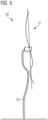
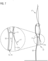
- Figure 7 shows a determination of an actual shape 20 based on lidar data 17
- Figure 7 a wind turbine 50 with corresponding rotor blades 51 and a tower 52 is shown. It can be seen how the lidar data 17 that were determined deviate from the actual course 51a of the rotor blades 51.
- the actual shape 20 is approximated by means of an approximate shape, namely the first eigenshape 70. This is placed through the end of the rotor blades 51, which adjoins the hub 53, as well as through the next point 71 of the lidar data 17 Tower 52.
- FIG 7 the corresponding lidar data from tower 52 can be seen. It can be seen how the distance 73 to these based on the actual shape 20 is significantly smaller than the distance 72 based on the respective lidar data of the rotor blade 51.
- the distance 73 can be defined as the actual tower clearance 74.
- Figure 8 describes the regulation of the actual tower clearance 74.
- FIG 8 divided into three areas.
- In the middle there is a schematic wind turbine 50 comprising rotor blades 51 and a tower 52, with the actual tower clearance 74 being shown purely schematically.
- the actual tower clearance 74 is shown on the Y-axis of the diagram and the corresponding time is shown on the X-axis.
- On the left side it is now shown how the actual tower clearance 74 flows into a corresponding control loop.
- the actual tower clearance 74 is compared with the target range 75.
- a pitch adjustment unit 29 can influence the wind turbine 50, namely the pitch of the rotor blades, in order to regulate the actual tower clearance 74.
- the actual tower clearance 74 can be determined again using the evaluation unit 13.
Claims (11)
- Procédé (100) de fonctionnement d'une éolienne (50) comprenant plusieurs pales de rotor (51), dans lequel le procédé (100) comprend une pluralité de mesures (103) au moyen d'au moins un premier capteur lidar (11a) pour déterminer (105) des données lidar (17), dans lequel le au moins un premier capteur lidar (11a) consiste en un capteur lidar à semi-conducteurs, le au moins un premier capteur lidar (11a) est disposé à l'extérieur de l'éolienne (50) de telle sorte que le premier capteur lidar (11a) tourne avec les pales du rotor (51) de l'éolienne (50), dans lequel sur la base des données lidar (17), un état structurel réel d'au moins un point d'une pale de rotor (51) de l'éolienne (50) est observé, dans lequel un point dont l'état structurel réel est observé est désigné comme le point à observer (22), dans lequel l'état structurel réel du point (22) à observer comprend une déviation du point par rapport à une position normale et/ou une vitesse du point et/ou une accélération du point, dans lequel le procédé comprend la détermination (110) d'une forme réelle de la pale de rotor (51), dans lequel la détermination (110) comprend une approximation (111) de la forme réelle de la pale de rotor sur la base d'au moins une fonction d'approximation, dans lequel la première et/ou la deuxième et/ou la troisième forme naturelle de la pale de rotor (51) est utilisée comme fonction d'approximation, dans lequel le procédé (100) comprend une détermination (113) de l'au moins un point (22) à observer sur la base de la forme réelle.
- Procédé (100) selon la revendication 1, caractérisé en ce que le procédé (100) comprend la définition précédente (101) d'au moins un état d'éolienne (25), dans lequel un état d'éolienne (25) est défini par au moins un état environnemental et au moins un état de fonctionnement.
- Procédé (100) selon la revendication 2, caractérisé en ce que l'état environnemental comprend une condition de vent, dans lequel l'état de vent est une direction et/ou une intensité de turbulence et/ou une dérive du vent par rapport à l'altitude et/ou une vitesse moyenne et/ou un cisaillement du vent, ou dans lequel l'état environnemental comprend une condition de houle, dans lequel l'état de houle comprend une vitesse de propagation tridimensionnelle et un profil de hauteur de la vitesse de propagation de houle.
- Procédé (100) selon la revendication 2 ou 3, caractérisé en ce que l'état de fonctionnement comprend un état de pas de la pale de rotor (51) et/ou une vitesse de rotor de l'éolienne (50) et/ou une puissance de l'éolienne (50).
- Procédé (100) selon la revendication 1, caractérisé en ce que le procédé (100) comprend une segmentation (112) des données lidar (17) du au moins un premier capteur lidar (11a) pour l'au moins une pale de rotor (51) avant qu'une forme réelle (20) soit déterminée à partir des données lidar (17).
- Procédé (100) selon une des revendications 1 ou 5, caractérisé en ce que l'état structurel réel du point à observer est comparé (114) aux données lidar (17).
- Procédé (100) selon une quelconque des revendications précédentes, caractérisé en ce que l'état structurel réel est suivi dans le temps (116), de sorte qu'une trajectoire (23a) de l'état structurel réel soit créée.
- Procédé (100) selon une des revendications 6 ou 7,
caractérisé en ce que le procédé comprend la dérivation (130) d'au moins une grandeur d'influence pour commander l'éolienne (50). - Procédé (100) selon une quelconque des revendications précédentes, caractérisé en ce que le procédé (100) comprend une pluralité de mesures utilisant au moins un deuxième capteur lidar (11b) pour déterminer des données lidar (17),dans lequel l'au moins un deuxième capteur lidar (11b) consiste en un capteur lidar à semi-conducteurs,dans lequel l'au moins un deuxième capteur lidar (11b) est agencé à l'extérieur de l'éolienne (50) de telle sorte que le deuxième capteur lidar (11b) ne tourne pas avec les pales de rotor (51) de l'éolienne (50),dans lequel une forme réelle de la tour (52) est déterminée sur la base des données lidar (17),dans lequel le procédé comprend l'observation d'un état structurel réel d'au moins un point de la tour de l'éolienne,dans lequel une grandeur d'influence pour commander l'éolienne (50) est un jeu de tour réel de l'éolienne (50),dans lequel un état structurel réel d'au moins un point respectivement de toutes les pales du rotor est observé,dans lequel l'état réel d'un point observé sur la forme réelle de la tour est observé, qui est le plus proche de la forme réelle des pales du rotor,dans lequel l'état réel d'un point est observé sur la forme réelle des pales du rotor, qui est située au plus près de la forme réelle de la tour,dans lequel le jeu réel de la tour est déterminé à partir de la distance entre les deux points.
- Dispositif (10) de fonctionnement d'une éolienne (50) comprenant plusieurs pales de rotor (51), dans lequel le dispositif (10) comprend au moins un premier capteur lidar (11a) pour effectuer une pluralité de mesures et déterminer des données lidar (17),dans lequel le dispositif (10) comprend en outre une unité d'évaluation (13) pour observer l'état structurel réel d'au moins un point d'une pale de rotor (51) de l'éolienne (50),dans lequel l'au moins un premier capteur lidar (11a) est situé à l'extérieur de l'éolienne (50) de manière à ce que le premier capteur lidar (11a) tourne avec les pales de rotor (51) de l'éolienne (50),dans lequel un point, dont l'état structurel réel est observé, est désigné comme le point à observer (22),dans lequel l'état structurel réel du point (22) à observer comprend une déviation du point par rapport à une position normale et/ou une vitesse du point et /ou une accélération du point,dans lequel le dispositif (10) est adapté pour mettre en oeuvre un procédé (100) selon une des revendications 1 à 9.
- Produit de programme informatique, qui comprend un support de mémorisation lisible par ordinateur sur lequel est mémorisé un programme qui, après avoir été chargé dans la mémoire de l'ordinateur, permet à un ordinateur de mettre en oeuvre un procédé (100) selon une quelconque des revendications 1 à 9 en relation avec un dispositif (10) selon la revendication 10.
Priority Applications (2)
| Application Number | Priority Date | Filing Date | Title |
|---|---|---|---|
| EP20212975.5A EP4012174B1 (fr) | 2020-12-10 | 2020-12-10 | Procédé et dispositif de fonctionnement d'une éolienne |
| PCT/EP2021/080542 WO2022122257A1 (fr) | 2020-12-10 | 2021-11-03 | Procédé et dispositif de mise en fonctionnement d'une éolienne |
Applications Claiming Priority (1)
| Application Number | Priority Date | Filing Date | Title |
|---|---|---|---|
| EP20212975.5A EP4012174B1 (fr) | 2020-12-10 | 2020-12-10 | Procédé et dispositif de fonctionnement d'une éolienne |
Publications (2)
| Publication Number | Publication Date |
|---|---|
| EP4012174A1 EP4012174A1 (fr) | 2022-06-15 |
| EP4012174B1 true EP4012174B1 (fr) | 2023-10-11 |
Family
ID=73792994
Family Applications (1)
| Application Number | Title | Priority Date | Filing Date |
|---|---|---|---|
| EP20212975.5A Active EP4012174B1 (fr) | 2020-12-10 | 2020-12-10 | Procédé et dispositif de fonctionnement d'une éolienne |
Country Status (2)
| Country | Link |
|---|---|
| EP (1) | EP4012174B1 (fr) |
| WO (1) | WO2022122257A1 (fr) |
Family Cites Families (2)
| Publication number | Priority date | Publication date | Assignee | Title |
|---|---|---|---|---|
| EP3555561B1 (fr) * | 2016-12-16 | 2023-09-06 | Innergex Inc. | Système et procédé de surveillance de la déviation des pales d'éoliennes |
| EP3339639A1 (fr) * | 2016-12-21 | 2018-06-27 | Vestas Wind Systems A/S | Système de surveillance d'une pale de turbine éolienne |
-
2020
- 2020-12-10 EP EP20212975.5A patent/EP4012174B1/fr active Active
-
2021
- 2021-11-03 WO PCT/EP2021/080542 patent/WO2022122257A1/fr active Application Filing
Also Published As
| Publication number | Publication date |
|---|---|
| EP4012174A1 (fr) | 2022-06-15 |
| WO2022122257A1 (fr) | 2022-06-16 |
Similar Documents
| Publication | Publication Date | Title |
|---|---|---|
| EP2861867B1 (fr) | Éolienne et procédé de commande d'une éolienne ou d'un parc éolien | |
| EP1132614B1 (fr) | Système de réglage pour une éolienne | |
| EP1817496B1 (fr) | Procede pour optimaliser le fonctionnement d'installations d'energie eolienne | |
| EP2225461B1 (fr) | Procédé permettant de faire fontionner une éolienne | |
| EP2582972B1 (fr) | Procédé et dispositif empêchant une oscillation transversale d'une éolienne | |
| DE112012005771T5 (de) | Windkraftanlage und Verfahren zum Bestimmen von Windkraftanlagenparametern | |
| DE102008020154A1 (de) | Verfahren zum Betreiben einer Windenergieanlage | |
| EP1972781A2 (fr) | Amortissement d'oscillations d'une éolienne | |
| DE102015112594A1 (de) | System und Verfahren für den verbesserten Betrieb von Windparks | |
| EP2956661A1 (fr) | Procédé permettant de contrôler le fonctionnement d'une éolienne et éolienne | |
| DE102009030886A1 (de) | Windenergieanlage mit einer Vielzahl von Windenergievorrichtungen und Verfahren zur Steuerung der Windenergieanlage | |
| DE602004001726T2 (de) | Windkraftanlage mit waagerechter Welle und Verfahren zur Messung des Aufwärtsströmungswinkels | |
| EP4012174B1 (fr) | Procédé et dispositif de fonctionnement d'une éolienne | |
| EP3124787B1 (fr) | Commande et procede de commande d'eolienne | |
| DE102012024272A1 (de) | Verfahren und Vorrichtung zum Verringern eines Rotors einer Windenergieanlage belastenden Nickmoments | |
| EP4227523A1 (fr) | Procédé de fonctionnement d'un parc éolien, éolienne et parc éolien | |
| EP4116576A1 (fr) | Procédé de détection d'une charge extrême sur une éolienne | |
| EP3717770B1 (fr) | Système de régulation destiné à réguler une turbine, procédé destiné à réguler une turbine et turbine d'éolienne | |
| EP3983674B1 (fr) | Procédé permettant de détecter la vitesse du vent, procédé permettant de commander une éolienne, procédé permettant de commander un parc éolien; et éolienne | |
| EP3995691A1 (fr) | Procédé de fonctionnement d'une éolienne, éolienne et parc éolien | |
| EP3499023A1 (fr) | Procédé et système de fonctionnement d'une éolienne | |
| EP3768970B1 (fr) | Procédé pour faire fonctionner une éolienne, éolienne et parc éolien | |
| EP4012171B1 (fr) | Procédé de réglage d'au moins une pale de rotor d'une éolienne ainsi que système et éolienne destinés à la mise en oeuvre du procédé | |
| EP3859146B1 (fr) | Procédé de détermination d'une direction du vent sur une éolienne, système de détermination d'une direction du vent et éolienne | |
| DE102018008391A1 (de) | Steuerung einer Windenegaieanlage |
Legal Events
| Date | Code | Title | Description |
|---|---|---|---|
| PUAI | Public reference made under article 153(3) epc to a published international application that has entered the european phase |
Free format text: ORIGINAL CODE: 0009012 |
|
| STAA | Information on the status of an ep patent application or granted ep patent |
Free format text: STATUS: REQUEST FOR EXAMINATION WAS MADE |
|
| 17P | Request for examination filed |
Effective date: 20220330 |
|
| AK | Designated contracting states |
Kind code of ref document: A1 Designated state(s): AL AT BE BG CH CY CZ DE DK EE ES FI FR GB GR HR HU IE IS IT LI LT LU LV MC MK MT NL NO PL PT RO RS SE SI SK SM TR |
|
| GRAP | Despatch of communication of intention to grant a patent |
Free format text: ORIGINAL CODE: EPIDOSNIGR1 |
|
| STAA | Information on the status of an ep patent application or granted ep patent |
Free format text: STATUS: GRANT OF PATENT IS INTENDED |
|
| RAP1 | Party data changed (applicant data changed or rights of an application transferred) |
Owner name: MICROVISION, INC. |
|
| INTG | Intention to grant announced |
Effective date: 20230517 |
|
| GRAJ | Information related to disapproval of communication of intention to grant by the applicant or resumption of examination proceedings by the epo deleted |
Free format text: ORIGINAL CODE: EPIDOSDIGR1 |
|
| P01 | Opt-out of the competence of the unified patent court (upc) registered |
Effective date: 20230530 |
|
| STAA | Information on the status of an ep patent application or granted ep patent |
Free format text: STATUS: REQUEST FOR EXAMINATION WAS MADE |
|
| INTC | Intention to grant announced (deleted) | ||
| GRAS | Grant fee paid |
Free format text: ORIGINAL CODE: EPIDOSNIGR3 |
|
| STAA | Information on the status of an ep patent application or granted ep patent |
Free format text: STATUS: GRANT OF PATENT IS INTENDED |
|
| GRAP | Despatch of communication of intention to grant a patent |
Free format text: ORIGINAL CODE: EPIDOSNIGR1 |
|
| GRAA | (expected) grant |
Free format text: ORIGINAL CODE: 0009210 |
|
| STAA | Information on the status of an ep patent application or granted ep patent |
Free format text: STATUS: THE PATENT HAS BEEN GRANTED |
|
| INTG | Intention to grant announced |
Effective date: 20230904 |
|
| AK | Designated contracting states |
Kind code of ref document: B1 Designated state(s): AL AT BE BG CH CY CZ DE DK EE ES FI FR GB GR HR HU IE IS IT LI LT LU LV MC MK MT NL NO PL PT RO RS SE SI SK SM TR |
|
| REG | Reference to a national code |
Ref country code: GB Ref legal event code: FG4D Free format text: NOT ENGLISH |
|
| REG | Reference to a national code |
Ref country code: CH Ref legal event code: EP |
|
| REG | Reference to a national code |
Ref country code: DE Ref legal event code: R096 Ref document number: 502020005604 Country of ref document: DE |
|
| REG | Reference to a national code |
Ref country code: IE Ref legal event code: FG4D Free format text: LANGUAGE OF EP DOCUMENT: GERMAN |
|
| PGFP | Annual fee paid to national office [announced via postgrant information from national office to epo] |
Ref country code: FR Payment date: 20231024 Year of fee payment: 4 Ref country code: DE Payment date: 20231024 Year of fee payment: 4 |
|
| REG | Reference to a national code |
Ref country code: LT Ref legal event code: MG9D |
|
| REG | Reference to a national code |
Ref country code: NL Ref legal event code: MP Effective date: 20231011 |
|
| PG25 | Lapsed in a contracting state [announced via postgrant information from national office to epo] |
Ref country code: NL Free format text: LAPSE BECAUSE OF FAILURE TO SUBMIT A TRANSLATION OF THE DESCRIPTION OR TO PAY THE FEE WITHIN THE PRESCRIBED TIME-LIMIT Effective date: 20231011 |
|
| PG25 | Lapsed in a contracting state [announced via postgrant information from national office to epo] |
Ref country code: GR Free format text: LAPSE BECAUSE OF FAILURE TO SUBMIT A TRANSLATION OF THE DESCRIPTION OR TO PAY THE FEE WITHIN THE PRESCRIBED TIME-LIMIT Effective date: 20240112 |
|
| PG25 | Lapsed in a contracting state [announced via postgrant information from national office to epo] |
Ref country code: IS Free format text: LAPSE BECAUSE OF FAILURE TO SUBMIT A TRANSLATION OF THE DESCRIPTION OR TO PAY THE FEE WITHIN THE PRESCRIBED TIME-LIMIT Effective date: 20240211 |
|
| PG25 | Lapsed in a contracting state [announced via postgrant information from national office to epo] |
Ref country code: LT Free format text: LAPSE BECAUSE OF FAILURE TO SUBMIT A TRANSLATION OF THE DESCRIPTION OR TO PAY THE FEE WITHIN THE PRESCRIBED TIME-LIMIT Effective date: 20231011 |