EP4012170B1 - Mehrlappige bullnose-rampe - Google Patents
Mehrlappige bullnose-rampe Download PDFInfo
- Publication number
- EP4012170B1 EP4012170B1 EP21214174.1A EP21214174A EP4012170B1 EP 4012170 B1 EP4012170 B1 EP 4012170B1 EP 21214174 A EP21214174 A EP 21214174A EP 4012170 B1 EP4012170 B1 EP 4012170B1
- Authority
- EP
- European Patent Office
- Prior art keywords
- profile
- ramp
- bullnose
- slope
- curvature
- Prior art date
- Legal status (The legal status is an assumption and is not a legal conclusion. Google has not performed a legal analysis and makes no representation as to the accuracy of the status listed.)
- Active
Links
Images


Classifications
-
- B—PERFORMING OPERATIONS; TRANSPORTING
- B64—AIRCRAFT; AVIATION; COSMONAUTICS
- B64D—EQUIPMENT FOR FITTING IN OR TO AIRCRAFT; FLIGHT SUITS; PARACHUTES; ARRANGEMENT OR MOUNTING OF POWER PLANTS OR PROPULSION TRANSMISSIONS IN AIRCRAFT
- B64D33/00—Arrangement in aircraft of power plant parts or auxiliaries not otherwise provided for
-
- F—MECHANICAL ENGINEERING; LIGHTING; HEATING; WEAPONS; BLASTING
- F02—COMBUSTION ENGINES; HOT-GAS OR COMBUSTION-PRODUCT ENGINE PLANTS
- F02K—JET-PROPULSION PLANTS
- F02K1/00—Plants characterised by the form or arrangement of the jet pipe or nozzle; Jet pipes or nozzles peculiar thereto
- F02K1/54—Nozzles having means for reversing jet thrust
- F02K1/64—Reversing fan flow
- F02K1/70—Reversing fan flow using thrust reverser flaps or doors mounted on the fan housing
- F02K1/72—Reversing fan flow using thrust reverser flaps or doors mounted on the fan housing the aft end of the fan housing being movable to uncover openings in the fan housing for the reversed flow
-
- B—PERFORMING OPERATIONS; TRANSPORTING
- B64—AIRCRAFT; AVIATION; COSMONAUTICS
- B64D—EQUIPMENT FOR FITTING IN OR TO AIRCRAFT; FLIGHT SUITS; PARACHUTES; ARRANGEMENT OR MOUNTING OF POWER PLANTS OR PROPULSION TRANSMISSIONS IN AIRCRAFT
- B64D27/00—Arrangement or mounting of power plants in aircraft; Aircraft characterised by the type or position of power plants
- B64D27/02—Aircraft characterised by the type or position of power plants
- B64D27/10—Aircraft characterised by the type or position of power plants of gas-turbine type
-
- F—MECHANICAL ENGINEERING; LIGHTING; HEATING; WEAPONS; BLASTING
- F05—INDEXING SCHEMES RELATING TO ENGINES OR PUMPS IN VARIOUS SUBCLASSES OF CLASSES F01-F04
- F05D—INDEXING SCHEME FOR ASPECTS RELATING TO NON-POSITIVE-DISPLACEMENT MACHINES OR ENGINES, GAS-TURBINES OR JET-PROPULSION PLANTS
- F05D2250/00—Geometry
- F05D2250/70—Shape
- F05D2250/71—Shape curved
- F05D2250/713—Shape curved inflexed
-
- F—MECHANICAL ENGINEERING; LIGHTING; HEATING; WEAPONS; BLASTING
- F05—INDEXING SCHEMES RELATING TO ENGINES OR PUMPS IN VARIOUS SUBCLASSES OF CLASSES F01-F04
- F05D—INDEXING SCHEME FOR ASPECTS RELATING TO NON-POSITIVE-DISPLACEMENT MACHINES OR ENGINES, GAS-TURBINES OR JET-PROPULSION PLANTS
- F05D2270/00—Control
- F05D2270/01—Purpose of the control system
- F05D2270/17—Purpose of the control system to control boundary layer
Definitions
- the present disclosure relates generally to aircraft propulsion systems and, more particularly, to thrust reversers used in aircraft propulsion systems.
- Aircraft propulsion systems that employ gas turbine engines for thrust typically include a thrust reverser configured to regulate a bypass flow stream within a bypass duct of the gas turbine engine.
- the thrust reverser defines a forward-thrust configuration, in which the bypass flow stream is employed to generate thrust in a forward direction, and a reverse-thrust configuration, in which the bypass flow stream is employed to generate thrust in a reverse direction that is opposite the forward direction.
- Placing the thrust reverser in the reverse-thrust configuration generally redirects the bypass flow stream through a thrust reverser duct located radially outward of the bypass duct.
- the redirection typically includes a significant change in the direction of flow of the bypass flow stream.
- a bullnose ramp or fairing may be utilized to define an inner curvature of the directional change.
- the thrust reverser In order to provide a desired level of performance of the thrust reverser (or a desired magnitude of the reverse-thrust) it may be desirable to design the thrust reverser such that a boundary layer fluid flow within a boundary layer that is adjacent to the bullnose fairing does not separate from the bullnose fairing.
- the inner curvature that is defined by the bullnose ramp or fairing may be dictated by a desired mass flow rate of the bypass flow stream through the reverser duct, a desired average velocity of the bypass flow stream through the reverser duct or the desired magnitude of the reverse-thrust.
- EP 2863038 A1 and US 2015/308376 A1 disclosed prior art assemblies.
- a bullnose ramp for use in a thrust reverser is provided as set forth in claim 1.
- the change in slope between the forward portion and the aft portion is represented by a discontinuity.
- the discontinuity extends between the forward portion and the aft portion at an essentially constant axial position with respect to an axial direction.
- the forward portion is configured to induce separation of a bypass flow stream from a surface of the bullnose ramp and the aft portion is configured to induce reattachment of the bypass flow stream to the surface of the bullnose ramp
- the first profile is a first sinuous profile with respect to an axial direction.
- the second profile is a second sinuous profile with respect to the axial direction.
- the first sinuous profile is characterized by a first curvature profile, the first curvature profile extending from a forward axial position of the bullnose ramp to the transition portion.
- the second sinuous profile is characterized by a second curvature profile, the second curvature profile extending from the transition portion to an aft axial position of the bullnose ramp.
- the first curvature profile is characterized by a first set of curvature values
- the second curvature profile is characterized by a second set of curvature values
- the second set of curvature values is lesser in magnitude than the first set of curvature values
- a thrust reverser is provided according to claim 10.
- the change in slope between the forward portion and the aft portion is represented by a discontinuity in at least one of the change in slope or a rate of change in the change in slope.
- the discontinuity extends between the forward portion and the aft portion at an essentially constant axial position with respect to the axial direction.
- an assembly for an aircraft propulsion system is provided according to claim 13.
- the change in slope between the forward portion and the aft portion is represented by a discontinuity in at least one of the change in slope or a rate of change in the change in slope.
- the change in slope extends between the forward portion and the aft portion at an essentially constant axial position with respect to the axial direction.
- FIGS. 1A and 1B provide schematic illustrations of an aircraft propulsion system 100 with a thrust reverser 102 in a stowed position and a deployed position, respectively.
- the aircraft propulsion system 100 includes a nacelle 104 and a gas turbine engine housed within the nacelle 104.
- the gas turbine engine may be configured as a high-bypass turbofan engine or, alternatively, the gas turbine engine may be configured as any other type of gas turbine engine capable of propelling an aircraft during flight.
- the nacelle 104 is configured to house and provide an aerodynamic cover for the gas turbine engine.
- An outer structure of the nacelle 104 extends along an axial centerline A (or an axial direction) between a nacelle forward end 106 and a nacelle aft end 108.
- the nacelle 104 includes an inlet structure 110, one or more fan cowls 112 (e.g., a left-side fan cowl and a right-side fan cowl) and a nacelle aft structure 114, which is configured as part of or may include the thrust reverser 102.
- the inlet structure 110 is disposed at the nacelle forward end 106.
- the inlet structure 110 is configured to direct a stream of air through an inlet opening 116 at the nacelle forward end 106 and into a fan section of the gas turbine engine.
- Each of the one or more fan cowls 112 is typically disposed axially between the inlet structure 110 and the nacelle aft structure 114. Each of the one or more fan cowls 112 is disposed at ( e.g., on, adjacent or proximate) an aft end 118 of a stationary portion of the nacelle 104, and extends forward to the inlet structure 110. Each of the one or more fan cowls 112 is also generally axially aligned with a fan section of the gas turbine engine. The one or more fan cowls 112 are configured to provide an aerodynamic covering for a fan case 120, which circumscribes the fan section and partially forms a forward outer peripheral boundary of a bypass flow stream of the aircraft propulsion system 100.
- the term "stationary portion” is used above to describe a portion of the nacelle 104 that is stationary during operation of the aircraft propulsion system 100 ( e.g., during takeoff, aircraft flight and landing). However, the stationary portion may be otherwise movable, for example, to provide access for inspection or maintenance of the various components that comprise the aircraft propulsion system 100.
- the nacelle aft structure 114 includes a translating sleeve 122.
- the translating sleeve 122 is disposed at the nacelle aft end 108.
- the translating sleeve 122 extends axially along the axial centerline A (or an axial direction) between a forward end 124 thereof and the nacelle aft end 108.
- the translating sleeve 122 is configured to partially form an aft outer peripheral boundary of the bypass flow stream.
- the translating sleeve 122 may also be configured to form a bypass nozzle 126 for the bypass flow stream with an inner fixed structure of the nacelle 104, which nacelle inner fixed structure houses a core of the gas turbine engine.
- the translating sleeve 122 includes a pair of sleeve segments (e.g. , a first translating sleeve segment and a second translating sleeve segment) arranged on opposing sides of the aircraft propulsion system 100 (one such sleeve segment visible in FIGS. 1A and 1B ).
- the present disclosure is not limited to such an exemplary translating sleeve configuration.
- the translating sleeve 122 may alternatively have a substantially tubular body.
- the translating sleeve 122 may extend up to or more than three-hundred and thirty degrees (330°) about the axial centerline A.
- the translating sleeve 122 is an axially translatable structure.
- Each translating sleeve segment may be slidably connected to one or more stationary structures (e.g. , a pylon and a lower bifurcation) through one or more respective track assemblies.
- Each track assembly may include a rail mated with a track beam; however, the present disclosure is not limited to the foregoing exemplary sliding connection configuration.
- the translating sleeve 122 may translate axially along the axial centerline A and relative to the stationary portion. The translating sleeve 122 may thereby move axially between a forward or stowed position (see FIG.
- the translating sleeve 122 In the forward or stowed position, the translating sleeve 122 provides the functionality described above. In the aft or deployed position, the translating sleeve 122 at least partially (or substantially completely) uncovers at least one or more other components of the thrust reverser 102 such as, but not limited to, a cascade structure 128. In addition, as the translating sleeve 122 moves from the stowed position to the deployed position, one or more blocker doors ( see, e.g., the thrust reverser blocker door assembly 234 illustrated in FIG. 2B ) arranged with the translating sleeve 122 may be deployed to divert bypass air from the bypass flow stream through the cascade structure 128 to provide reverse thrust.
- one or more blocker doors see, e.g., the thrust reverser blocker door assembly 234 illustrated in FIG. 2B ) arranged with the translating sleeve 122 may be deployed to divert bypass air from the bypass flow stream through the cascade structure 1
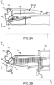
- FIGS. 2A and 2B a partial side-sectional illustration of a thrust reverser 202, similar to the thrust reverser 102 described above with reference to FIGS. 1A and 1B , is provided, in both a stowed position ( see FIG. 2A ) and a deployed position ( see FIG. 2B ).
- the thrust reverser 202 includes a nacelle fixed structure 230, a nacelle translating structure 232 and a thrust reverser blocker door assembly 234.
- the nacelle fixed structure 230 is located at an aft end 218 of a stationary portion of a nacelle, such as, for example, the aft end 118 of the stationary portion of the nacelle 104 described above with reference to FIGS. 1A and 1B .
- aft end 118 of the stationary portion of the nacelle 104 described above with reference to FIGS. 1A and 1B .
- the disclosure contemplates applicability to other types of thrust reversers and blocker door assemblies, including, for example, traditional drag-link style blocker doors mounted on an inner fixed structure. Accordingly, the disclosure should not be construed as limited to the thrust reverser and the related components illustrated at FIGS. 2A and 2B .
- the nacelle fixed structure 230 includes a bullnose ramp 240 (or a bullnose) and an internal nacelle support structure 242.
- bullnose originates from the rounded nose of a bull and typically refers to a smooth, rounded structure or a rounded edge on a surface or object having a smooth, rounded or finished appearance.
- the bullnose ramp 240 is configured to provide a smooth aerodynamic transition from a bypass flow stream B to a thrust reverser duct 244, which extends axially between the internal nacelle support structure 242 and the nacelle translating structure 232.
- the internal nacelle support structure 242 circumscribes and supports the bullnose ramp 240.
- the internal nacelle support structure 242 also provides a base to which a cascade structure 228, similar to the cascade structure 128 described above with reference to FIGS. 1A and 1B , may be mounted.
- the cascade structure 228 may thereby project axially aft from the internal nacelle support structure 242 and downstream of the bullnose ramp 240.
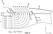
- the thrust reverser 302 includes a nacelle fixed structure 330, a nacelle translating structure 332 and a thrust reverser blocker door assembly 334.
- the nacelle fixed structure 330 includes a bullnose ramp 340 (or a bullnose) and an internal nacelle support structure 342.
- the bullnose ramp 340 is configured to provide a smooth aerodynamic transition from a bypass flow stream B to a thrust reverser duct 344, which extends axially between the internal nacelle support structure 342 and the nacelle translating structure 332.
- the internal nacelle support structure 342 circumscribes and supports the bullnose ramp 340.
- the internal nacelle support structure 342 also provides a base to which a cascade structure 328, similar to the cascade structure 228 described above with reference to FIGS. 2A and 2B , may be mounted.
- the cascade structure 328 may thereby project axially aft from the internal nacelle support structure 342 and downstream of the bullnose ramp 340.
- the cascade structure 328 When the nacelle translating structure 332 is in the deployed position, the cascade structure 328 is uncovered and located within the thrust reverser duct 344. At the same time, a blocker door 335 of the thrust reverser blocker door assembly 334 is deployed, thereby blocking the bypass flow stream B from exiting the bypass flow stream exhaust and forcing the bypass flow stream to turn radially outward and exit the cascade structure 328 as a reverse thrust flow stream T.
- the bullnose ramp 340 provides an aerodynamic surface that functions to smoothly turn the bypass flow stream B toward the cascade structure 328.
- the bullnose ramp 340 may be characterized by a bullnose profile (or a ramp profile) that extends from a forward axial position 350 (or an axial ramp start) to an aft axial position 352 (or an axial ramp end).
- the bullnose profile may be characterized as a functional relationship between a radius R as a function of axial length X between the forward axial position 350 and the aft axial position 352.
- Additional parameters that may be used to characterize the bullnose profile and the radial position of the cascade structure 328 include the radius R of the forward axial position 350, R START , the radial position at the aft axial position 352, R END , and the radius of the cascade structure 328, R CASCADE .
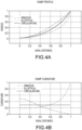
- FIGS. 4A and 4B graphs illustrating various ramp profiles and curvature profiles for a bullnose ramp are illustrated.
- curvature profile is used to enable the curvature to vary along an axial extent of the ramp profile, rather than be constant along the ramp profile.
- FIG. 4A three mathematical profiles - sinuous, elliptical and circular - are provided.
- the axial position along the X-axis is normalized to run from zero to unity, with zero corresponding to a forward axial position (e.g., the forward axial position 350) and unity corresponding to an aft axial position ( e.g., the aft axial position 352) of a bullnose ramp (e.g.
- the bullnose ramp 340 the bullnose ramp 340).
- the radial position along the Y-axis is normalized to run from zero to unity, with zero corresponding to R START and unity corresponding to R END of the bullnose ramp.
- FIG. 4B normalized values of curvature for the three mathematical profiles - sinuous, elliptical and circular - are provided.
- the axial position along the X-axis is normalized in the same fashion as for FIG. 4A , while the curvature along the Y-axis is suitably normalized to run from zero to unity.
- An important distinction to recognize from the profiles presented in FIGS. 4A and 4B is the relative degree of curvature for each of the profiles.
- the curvature of the sinuous profile starts at a start value (Y ⁇ 0.50) at the forward axial position, which is relatively high with respect to an end value (Y ⁇ 0.00) at the aft axial position, where Y indicates the value of curvature on the Y-axis as a function of the axial distance X on the X-axis (or axial extent along the X-axis).
- the curvature of the elliptical profile starts at a start value (Y ⁇ 0.20) at the forward axial position, which is relatively low with respect to an end value (Y ⁇ 1.00) at the aft axial position.
- the curvature for the circular arc is constant along the axial extent of the profile.
- Y refers to the local values of curvature illustrated at FIG. 4B , with the local values of curvature along the X-axis generally understood to mean a reciprocal of the local radii of curvature along the X-axis.
- the foregoing profiles may be considered in the design of a bullnose ramp for various thrust reverser configurations.
- current research suggests the profiles are not optimal for maximizing mass flow through a cascade, which, if successful, may result in an engine design configured to experience less drag during flight via shortening the thrust reverser portion of the engine. More specifically, maximizing the mass flow through the cascade enables the use of shorter cascades where flow separation along the bullnose ramp is reduced. Reducing the amount of flow separation along the bullnose ramp, particularly at the forward region of the cascade, enables an increase in the mass flow through the cascade and a more uniform reverse thrust flow stream T (see FIG. 3 ).
- the velocity vectors through the cascade at the forward region of the cascade may be reduced in magnitude, thereby reducing the mass flow through the cascade and thereby reducing the magnitude of the reverse thrust.
- FIG. 5 a compound profile for a bullnose ramp, such as, for example, the bullnose ramp 240 described above with reference to FIGS. 2A and 2B and the bullnose ramp 340 described above with reference to FIG. 3 , is illustrated.
- solutions to the drawbacks described above, including reducing flow separation along the bullnose ramp, particularly in the region radially inward of the forward region of the cascade are accomplished by introducing a transition portion, which, in various embodiments, may be represented by a discontinuity 560, in the profile of the bullnose ramp, with the discontinuity 560 separating a first profile 562 (or a first axial profile) from a second profile 564 (or a second axial profile), where the two profiles exhibit different degrees of curvature along their axial extent.
- a transition portion which, in various embodiments, may be represented by a discontinuity 560, in the profile of the bullnose ramp, with the discontinuity 560 separating a first profile 562 (or a first axial profile) from a second profile 564 (or a second axial profile), where the two profiles exhibit different degrees of curvature along their axial extent.
- the first profile 562 (“Profile 1") exhibits a larger or greater degree of curvature along the length of the profile (or a smaller or lesser radius of curvature) than does the second profile 564 (“Profile 2").
- the first profile 562 may be characterized by a first curvature profile or a first set of curvature values that extend along the axial length of Profile 1
- the second profile 564 may be characterized by a second curvature profile or a second set of curvature values that extend along the axial length of Profile 2.
- a compound profile 566 is constructed by employing the first profile 562 from a forward axial position (X ⁇ 0.00) ( e.g. , the forward axial position 350 described above with reference to FIG.
- the compound profile 566 then continues from the discontinuity 560 by incorporating the second profile 564 to an aft axial position (X ⁇ 1.00) ( e.g., the aft axial position 352 described above with reference to FIG. 3 ).
- the second profile 564 is incorporated into the compound profile 566 by translating the second profile 564 in a forward direction F, from an axial position (X ⁇ 0.90), where the radial value 568 of the second profile 564 is equal to the radial value of the first profile 562 at the discontinuity 560, to the end of the second profile (X ⁇ 1.20), with the shift, ⁇ X, being approximately equal to ⁇ X ⁇ 0.2, as illustrated.
- each of Profile 1 and Profile 2 is also, according to the claimed invention, characterized by a slope (e.g. , the first derivative of the ramp profile) or may also, in examples not forming part of the claimed invention, be characterized by a rate of change in slope ( e.g. , the second derivative of the ramp profile) along the axial extent.
- the ramp profile extending along the transition portion and, in particular, the discontinuity 560 may be characterized as being C 0 , C 1 or C 2 continuous.
- the discontinuity may be manifest as a crease 241 that extends along an intersection of the bullnose ramp 240 between a forward portion 243 (represented by the first profile 562) and an aft portion 245 (represented by the second profile 564). As illustrated, the crease 241 extends about the bullnose ramp 240 at an essentially constant axial position. In various embodiments, the axial location of the discontinuity 560 (or the crease 241 illustrated in FIG.
- Positioning the discontinuity 560 at an axial location proximate the onset of flow separation allows, or even induces, the flow to separate and then immediately reattach downstream of the discontinuity 560 and on the second profile 564, which, as described above, is characterized by a second set of curvature values having a generally smaller curvature (or larger radius of curvature) than that of a first set of curvature values that characterize the first profile 562.
- the smaller curvature of the second profile 564 provides a surface less amenable to flow separation throughout the remainder of the compound profile 566, thereby providing a more uniform flow, particularly at the forward region of the cascade, which thereby enables an increase in the mass flow through the cascade and a more uniform reverse thrust flow stream T ( see FIG. 3 ).
- the first and second sets of curvature values might be further characterized by integrating the curvature along the lengths of the first and second profiles (taking care to scale any differences in lengths of the profiles) to obtain scalar results representative of the average curvature of the two profiles.
- the foregoing disclosure provides an apparatus and method to improve or increase the mass flow rate through a cascade of a thrust reverser.
- the bullnose structures disclosed above which include the surface profiles of the structures generally immediately upstream of the cascade, prevent or impede flow separation in an upstream region of the cascade where a bypass flow stream is being turned or redirected into the bypass duct where the cascade is positioned.
- the characteristics of the improved flow field e.g., a flow field exhibiting minimal flow separation from the surface of the bullnose) enables the use of cascades having reduced axial length.
- a reduction in the axial length of the cascade enables a reduction in the length of the translating sleeve of the thrust reverser, thereby reducing weight of the propulsion system and reducing aerodynamic drag experienced at the outer surface of the nacelle of the propulsion system during flight.
Landscapes
- Engineering & Computer Science (AREA)
- Aviation & Aerospace Engineering (AREA)
- Chemical & Material Sciences (AREA)
- Combustion & Propulsion (AREA)
- Mechanical Engineering (AREA)
- General Engineering & Computer Science (AREA)
- Structures Of Non-Positive Displacement Pumps (AREA)
Claims (15)
- Bullnose-Rampe (240, 340) zur Verwendung in einem Schubumkehrer, umfassend:einen vorderen Abschnitt (243), wobei der vordere Abschnitt (243) durch ein erstes Profil (562) gekennzeichnet ist, das eine erste Neigung aufweist und sich von einer vorderen axialen Position (350) zu einer axialen Zwischenposition erstreckt;einen hinteren Abschnitt (245), wobei der hintere Abschnitt (245) durch ein zweites Profil (564) gekennzeichnet ist, das eine zweite Neigung aufweist und sich von der axialen Zwischenposition zu einer hinteren axialen Position (352) erstreckt; undeinen Übergangsabschnitt (560), der an der axialen Zwischenposition zwischen dem vorderen Abschnitt (243) und dem hinteren Abschnitt (245) positioniert ist, wobei der Übergangsabschnitt (560) einen Neigungswechsel von der ersten Neigung zu der zweiten Neigung zwischen dem ersten Profil (562) und dem zweiten Profil (564) definiert.
- Bullnose-Rampe (240, 340) nach Anspruch 1, wobei die Neigungsänderung zwischen dem vorderen Abschnitt (243) und dem hinteren Abschnitt (245) durch eine Diskontinuität (560) dargestellt ist.
- Bullnose-Rampe (240, 340) nach Anspruch 2, wobei sich die Diskontinuität (560) zwischen dem vorderen Abschnitt (243) und dem hinteren Abschnitt (245) an einer im Wesentlichen konstanten axialen Position in Bezug auf eine axiale Richtung erstreckt.
- Bullnose-Rampe (240, 340) nach Anspruch 1, 2 oder 3, wobei der vordere Abschnitt (243) dazu konfiguriert ist, eine Trennung eines Umgehungsdurchflussstroms (B) von einer Oberfläche der Bullnose-Rampe (240, 340) zu bewirken, und der hintere Abschnitt (245) dazu konfiguriert ist, eine Wiederanbringung des Umgehungsdurchflussstroms (B) an der Oberfläche der Bullnose-Rampe (240, 340) zu bewirken.
- Bullnose-Rampe (240, 340) nach einem der vorhergehenden Ansprüche, wobei das erste Profil (562) in Bezug auf eine axiale Richtung ein erstes gewundenes Profil ist.
- Bullnose-Rampe (240, 340) nach Anspruch 5, wobei das erste gewundene Profil durch ein erstes Krümmungsprofil gekennzeichnet ist, wobei sich das erste Krümmungsprofil von der vorderen axialen Position der Bullnose-Rampe (240, 340) zu dem Übergangsabschnitt (560) erstreckt.
- Bullnose-Rampe (240, 340) nach Anspruch 5 oder 6, wobei das zweite Profil (564) in Bezug auf die axiale Richtung ein zweites gewundenes Profil ist.
- Bullnose-Rampe (240, 340) nach Anspruch 7, wobei das zweite gewundene Profil durch ein zweites Krümmungsprofil gekennzeichnet ist, wobei sich das zweite Krümmungsprofil von dem Übergangsabschnitt (560) zu der hinteren axialen Position der Bullnose-Rampe (240, 340) erstreckt.
- Bullnose-Rampe (240, 340) nach den Ansprüchen 6 und 8, wobei das erste Krümmungsprofil durch einen ersten Satz von Krümmungswerten gekennzeichnet ist, das zweite Krümmungsprofil durch einen zweiten Satz von Krümmungswerten gekennzeichnet ist und der zweite Satz von Krümmungswerten eine geringere Größe als der erste Satz von Krümmungswerten aufweist.
- Schubumkehrer (202, 302), umfassend:eine Kaskade (228, 328); unddie Bullnose-Rampe (240, 340) nach einem der vorhergehenden Ansprüche, die in einer axialen Richtung stromaufwärts der Kaskade (228, 328) angeordnet ist.
- Schubumkehrer (202, 302) nach Anspruch 10, wobei die Neigungsänderung zwischen dem vorderen Abschnitt (243) und dem hinteren Abschnitt (245) durch eine Diskontinuität (560) in mindestens einer von der Neigungsänderung oder einer Änderungsrate der Neigungsänderung dargestellt wird.
- Schubumkehrer nach Anspruch 11, wobei sich die Diskontinuität (560) zwischen dem vorderen Abschnitt (243) und dem hinteren Abschnitt (245) an einer im Wesentlichen konstanten axialen Position in Bezug auf die axiale Richtung erstreckt.
- Baugruppe für ein Luftfahrzeugantriebssystem, umfassend:eine Gondel (104), wobei die Gondel (104) eine Gondelverschiebestruktur (232, 332) umfasst;eine Kaskade (228, 328), die innerhalb eines Schubumkehrkanals (244, 344) angeordnet ist;eine Blockiertür (335), die dazu konfiguriert ist, einen Abschnitt eines Umgehungsdurchflussstroms (B) zu blockieren; unddie Bullnose-Rampe (240, 340) nach einem der Ansprüche 1 bis 9, die in einer axialen Richtung stromaufwärts der Kaskade (228, 328) angeordnet ist, wobei das erste Profil ein erstes axiales Profil ist und das zweite Profil ein zweites axiales Profil ist.
- Baugruppe nach Anspruch 13, wobei die Neigungsänderung zwischen dem vorderen Abschnitt (243) und dem hinteren Abschnitt (245) durch eine Diskontinuität (560) in mindestens einer von der Neigungsänderung oder einer Änderungsrate der Neigungsänderung dargestellt wird.
- Baugruppe nach Anspruch 13 oder 14, wobei sich die Neigungsänderung zwischen dem vorderen Abschnitt (243) und dem hinteren Abschnitt (245) an einer im Wesentlichen konstanten axialen Position in Bezug auf die axiale Richtung erstreckt.
Applications Claiming Priority (2)
| Application Number | Priority Date | Filing Date | Title |
|---|---|---|---|
| IN202011054154 | 2020-12-12 | ||
| US17/501,862 US11802523B2 (en) | 2020-12-12 | 2021-10-14 | Multi-lobed bullnose ramp |
Publications (2)
| Publication Number | Publication Date |
|---|---|
| EP4012170A1 EP4012170A1 (de) | 2022-06-15 |
| EP4012170B1 true EP4012170B1 (de) | 2024-09-18 |
Family
ID=78851321
Family Applications (1)
| Application Number | Title | Priority Date | Filing Date |
|---|---|---|---|
| EP21214174.1A Active EP4012170B1 (de) | 2020-12-12 | 2021-12-13 | Mehrlappige bullnose-rampe |
Country Status (2)
| Country | Link |
|---|---|
| EP (1) | EP4012170B1 (de) |
| CN (1) | CN114620238A (de) |
Family Cites Families (10)
| Publication number | Priority date | Publication date | Assignee | Title |
|---|---|---|---|---|
| US8201390B2 (en) * | 2007-12-12 | 2012-06-19 | Spirit Aerosystems, Inc. | Partial cascade thrust reverser |
| EP3047133A4 (de) * | 2013-09-19 | 2017-05-10 | United Technologies Corporation | Erweiterte schubumkehrerkaskade |
| US9765729B2 (en) * | 2013-10-17 | 2017-09-19 | Rohr, Inc. | Thrust reverser fan ramp with blocker door pocket |
| US20150107222A1 (en) * | 2013-10-18 | 2015-04-23 | Rohr, Inc. | Thrust reverser fan ramp partially formed on aft end of fan case |
| US9371799B2 (en) * | 2014-04-24 | 2016-06-21 | The Boeing Company | Thrust-reverser assemblies that utilize active flow-control and systems and methods including the same |
| US9387933B2 (en) * | 2014-04-25 | 2016-07-12 | Rohr, Inc. | Ladder cascade torque box |
| US20160273488A1 (en) * | 2015-03-19 | 2016-09-22 | Rohr, Inc. | Cascade vane leading edge |
| US20160341150A1 (en) * | 2015-05-21 | 2016-11-24 | The Boeing Company | Thrust Reverser System and Method with Flow Separation-Inhibiting Blades |
| US10184426B2 (en) * | 2015-06-22 | 2019-01-22 | Rohr, Inc. | Thrust reverser with forward positioned blocker doors |
| GB201815759D0 (en) * | 2018-09-27 | 2018-11-14 | Rolls Royce Plc | Nacelle intake |
-
2021
- 2021-12-10 CN CN202111507313.2A patent/CN114620238A/zh active Pending
- 2021-12-13 EP EP21214174.1A patent/EP4012170B1/de active Active
Also Published As
| Publication number | Publication date |
|---|---|
| EP4012170A1 (de) | 2022-06-15 |
| CN114620238A (zh) | 2022-06-14 |
Similar Documents
| Publication | Publication Date | Title |
|---|---|---|
| EP3594482B1 (de) | Schubumkehrer mit blockerklappensystem | |
| EP2388193B1 (de) | Führungssystem für Triebwerksgondel | |
| US8505307B2 (en) | Translating variable area fan nozzle with split beavertail fairings | |
| EP2399827B1 (de) | Führungssystem für eine Triebwerksgondelanordnung | |
| EP3626959B1 (de) | Schubumkehrer mit schubumkehrklappenfaltgestänge | |
| US10184426B2 (en) | Thrust reverser with forward positioned blocker doors | |
| US11788488B2 (en) | Featured bullnose ramp for a thrust reverser system | |
| US9759087B2 (en) | Translating variable area fan nozzle providing an upstream bypass flow exit | |
| US20160230702A1 (en) | Extended thrust reverser cascade | |
| EP4163487B1 (de) | Schubumkehrsystem mit verborgener drehtür | |
| EP2278147B1 (de) | Flachstrahldüse mit Umsetzung verschiedener Bereiche, die einen stromaufwärtigen Nebenstromaustritt bereitstellt | |
| US10428763B2 (en) | Controlling a relative position at an interface between translating structures of an aircraft nacelle | |
| US11802523B2 (en) | Multi-lobed bullnose ramp | |
| EP4012170B1 (de) | Mehrlappige bullnose-rampe | |
| EP2239449B1 (de) | Gondelanordnung für Mantelstromtriebwerke von Flugzeugen | |
| EP4428356A1 (de) | Schubumkehrvorrichtung mit blockiertürfaltverbindung | |
| US12331701B1 (en) | Thrust reverser blocker door with fairing |
Legal Events
| Date | Code | Title | Description |
|---|---|---|---|
| PUAI | Public reference made under article 153(3) epc to a published international application that has entered the european phase |
Free format text: ORIGINAL CODE: 0009012 |
|
| STAA | Information on the status of an ep patent application or granted ep patent |
Free format text: STATUS: THE APPLICATION HAS BEEN PUBLISHED |
|
| AK | Designated contracting states |
Kind code of ref document: A1 Designated state(s): AL AT BE BG CH CY CZ DE DK EE ES FI FR GB GR HR HU IE IS IT LI LT LU LV MC MK MT NL NO PL PT RO RS SE SI SK SM TR |
|
| STAA | Information on the status of an ep patent application or granted ep patent |
Free format text: STATUS: REQUEST FOR EXAMINATION WAS MADE |
|
| 17P | Request for examination filed |
Effective date: 20221214 |
|
| RBV | Designated contracting states (corrected) |
Designated state(s): AL AT BE BG CH CY CZ DE DK EE ES FI FR GB GR HR HU IE IS IT LI LT LU LV MC MK MT NL NO PL PT RO RS SE SI SK SM TR |
|
| GRAP | Despatch of communication of intention to grant a patent |
Free format text: ORIGINAL CODE: EPIDOSNIGR1 |
|
| STAA | Information on the status of an ep patent application or granted ep patent |
Free format text: STATUS: GRANT OF PATENT IS INTENDED |
|
| INTG | Intention to grant announced |
Effective date: 20240417 |
|
| GRAS | Grant fee paid |
Free format text: ORIGINAL CODE: EPIDOSNIGR3 |
|
| GRAA | (expected) grant |
Free format text: ORIGINAL CODE: 0009210 |
|
| STAA | Information on the status of an ep patent application or granted ep patent |
Free format text: STATUS: THE PATENT HAS BEEN GRANTED |
|
| AK | Designated contracting states |
Kind code of ref document: B1 Designated state(s): AL AT BE BG CH CY CZ DE DK EE ES FI FR GB GR HR HU IE IS IT LI LT LU LV MC MK MT NL NO PL PT RO RS SE SI SK SM TR |
|
| REG | Reference to a national code |
Ref country code: GB Ref legal event code: FG4D |
|
| REG | Reference to a national code |
Ref country code: CH Ref legal event code: EP |
|
| REG | Reference to a national code |
Ref country code: DE Ref legal event code: R096 Ref document number: 602021018925 Country of ref document: DE |
|
| REG | Reference to a national code |
Ref country code: IE Ref legal event code: FG4D |
|
| REG | Reference to a national code |
Ref country code: LT Ref legal event code: MG9D |
|
| PG25 | Lapsed in a contracting state [announced via postgrant information from national office to epo] |
Ref country code: NO Free format text: LAPSE BECAUSE OF FAILURE TO SUBMIT A TRANSLATION OF THE DESCRIPTION OR TO PAY THE FEE WITHIN THE PRESCRIBED TIME-LIMIT Effective date: 20241218 |
|
| PG25 | Lapsed in a contracting state [announced via postgrant information from national office to epo] |
Ref country code: GR Free format text: LAPSE BECAUSE OF FAILURE TO SUBMIT A TRANSLATION OF THE DESCRIPTION OR TO PAY THE FEE WITHIN THE PRESCRIBED TIME-LIMIT Effective date: 20241219 Ref country code: FI Free format text: LAPSE BECAUSE OF FAILURE TO SUBMIT A TRANSLATION OF THE DESCRIPTION OR TO PAY THE FEE WITHIN THE PRESCRIBED TIME-LIMIT Effective date: 20240918 |
|
| PG25 | Lapsed in a contracting state [announced via postgrant information from national office to epo] |
Ref country code: BG Free format text: LAPSE BECAUSE OF FAILURE TO SUBMIT A TRANSLATION OF THE DESCRIPTION OR TO PAY THE FEE WITHIN THE PRESCRIBED TIME-LIMIT Effective date: 20240918 |
|
| PG25 | Lapsed in a contracting state [announced via postgrant information from national office to epo] |
Ref country code: LV Free format text: LAPSE BECAUSE OF FAILURE TO SUBMIT A TRANSLATION OF THE DESCRIPTION OR TO PAY THE FEE WITHIN THE PRESCRIBED TIME-LIMIT Effective date: 20240918 |
|
| PG25 | Lapsed in a contracting state [announced via postgrant information from national office to epo] |
Ref country code: HR Free format text: LAPSE BECAUSE OF FAILURE TO SUBMIT A TRANSLATION OF THE DESCRIPTION OR TO PAY THE FEE WITHIN THE PRESCRIBED TIME-LIMIT Effective date: 20240918 |
|
| REG | Reference to a national code |
Ref country code: NL Ref legal event code: MP Effective date: 20240918 |
|
| PG25 | Lapsed in a contracting state [announced via postgrant information from national office to epo] |
Ref country code: RS Free format text: LAPSE BECAUSE OF FAILURE TO SUBMIT A TRANSLATION OF THE DESCRIPTION OR TO PAY THE FEE WITHIN THE PRESCRIBED TIME-LIMIT Effective date: 20241218 |
|
| PG25 | Lapsed in a contracting state [announced via postgrant information from national office to epo] |
Ref country code: RS Free format text: LAPSE BECAUSE OF FAILURE TO SUBMIT A TRANSLATION OF THE DESCRIPTION OR TO PAY THE FEE WITHIN THE PRESCRIBED TIME-LIMIT Effective date: 20241218 Ref country code: NO Free format text: LAPSE BECAUSE OF FAILURE TO SUBMIT A TRANSLATION OF THE DESCRIPTION OR TO PAY THE FEE WITHIN THE PRESCRIBED TIME-LIMIT Effective date: 20241218 Ref country code: LV Free format text: LAPSE BECAUSE OF FAILURE TO SUBMIT A TRANSLATION OF THE DESCRIPTION OR TO PAY THE FEE WITHIN THE PRESCRIBED TIME-LIMIT Effective date: 20240918 Ref country code: HR Free format text: LAPSE BECAUSE OF FAILURE TO SUBMIT A TRANSLATION OF THE DESCRIPTION OR TO PAY THE FEE WITHIN THE PRESCRIBED TIME-LIMIT Effective date: 20240918 Ref country code: GR Free format text: LAPSE BECAUSE OF FAILURE TO SUBMIT A TRANSLATION OF THE DESCRIPTION OR TO PAY THE FEE WITHIN THE PRESCRIBED TIME-LIMIT Effective date: 20241219 Ref country code: FI Free format text: LAPSE BECAUSE OF FAILURE TO SUBMIT A TRANSLATION OF THE DESCRIPTION OR TO PAY THE FEE WITHIN THE PRESCRIBED TIME-LIMIT Effective date: 20240918 Ref country code: BG Free format text: LAPSE BECAUSE OF FAILURE TO SUBMIT A TRANSLATION OF THE DESCRIPTION OR TO PAY THE FEE WITHIN THE PRESCRIBED TIME-LIMIT Effective date: 20240918 |
|
| REG | Reference to a national code |
Ref country code: AT Ref legal event code: MK05 Ref document number: 1724871 Country of ref document: AT Kind code of ref document: T Effective date: 20240918 |
|
| PG25 | Lapsed in a contracting state [announced via postgrant information from national office to epo] |
Ref country code: NL Free format text: LAPSE BECAUSE OF FAILURE TO SUBMIT A TRANSLATION OF THE DESCRIPTION OR TO PAY THE FEE WITHIN THE PRESCRIBED TIME-LIMIT Effective date: 20240918 |
|
| PG25 | Lapsed in a contracting state [announced via postgrant information from national office to epo] |
Ref country code: PT Free format text: LAPSE BECAUSE OF FAILURE TO SUBMIT A TRANSLATION OF THE DESCRIPTION OR TO PAY THE FEE WITHIN THE PRESCRIBED TIME-LIMIT Effective date: 20250120 Ref country code: IS Free format text: LAPSE BECAUSE OF FAILURE TO SUBMIT A TRANSLATION OF THE DESCRIPTION OR TO PAY THE FEE WITHIN THE PRESCRIBED TIME-LIMIT Effective date: 20250118 |
|
| PG25 | Lapsed in a contracting state [announced via postgrant information from national office to epo] |
Ref country code: RO Free format text: LAPSE BECAUSE OF FAILURE TO SUBMIT A TRANSLATION OF THE DESCRIPTION OR TO PAY THE FEE WITHIN THE PRESCRIBED TIME-LIMIT Effective date: 20240918 Ref country code: SM Free format text: LAPSE BECAUSE OF FAILURE TO SUBMIT A TRANSLATION OF THE DESCRIPTION OR TO PAY THE FEE WITHIN THE PRESCRIBED TIME-LIMIT Effective date: 20240918 |
|
| PG25 | Lapsed in a contracting state [announced via postgrant information from national office to epo] |
Ref country code: ES Free format text: LAPSE BECAUSE OF FAILURE TO SUBMIT A TRANSLATION OF THE DESCRIPTION OR TO PAY THE FEE WITHIN THE PRESCRIBED TIME-LIMIT Effective date: 20240918 |
|
| PG25 | Lapsed in a contracting state [announced via postgrant information from national office to epo] |
Ref country code: EE Free format text: LAPSE BECAUSE OF FAILURE TO SUBMIT A TRANSLATION OF THE DESCRIPTION OR TO PAY THE FEE WITHIN THE PRESCRIBED TIME-LIMIT Effective date: 20240918 Ref country code: AT Free format text: LAPSE BECAUSE OF FAILURE TO SUBMIT A TRANSLATION OF THE DESCRIPTION OR TO PAY THE FEE WITHIN THE PRESCRIBED TIME-LIMIT Effective date: 20240918 |
|
| PG25 | Lapsed in a contracting state [announced via postgrant information from national office to epo] |
Ref country code: CZ Free format text: LAPSE BECAUSE OF FAILURE TO SUBMIT A TRANSLATION OF THE DESCRIPTION OR TO PAY THE FEE WITHIN THE PRESCRIBED TIME-LIMIT Effective date: 20240918 Ref country code: PL Free format text: LAPSE BECAUSE OF FAILURE TO SUBMIT A TRANSLATION OF THE DESCRIPTION OR TO PAY THE FEE WITHIN THE PRESCRIBED TIME-LIMIT Effective date: 20240918 |
|
| PG25 | Lapsed in a contracting state [announced via postgrant information from national office to epo] |
Ref country code: SK Free format text: LAPSE BECAUSE OF FAILURE TO SUBMIT A TRANSLATION OF THE DESCRIPTION OR TO PAY THE FEE WITHIN THE PRESCRIBED TIME-LIMIT Effective date: 20240918 Ref country code: IT Free format text: LAPSE BECAUSE OF FAILURE TO SUBMIT A TRANSLATION OF THE DESCRIPTION OR TO PAY THE FEE WITHIN THE PRESCRIBED TIME-LIMIT Effective date: 20240918 |
|
| REG | Reference to a national code |
Ref country code: DE Ref legal event code: R097 Ref document number: 602021018925 Country of ref document: DE |
|
| PG25 | Lapsed in a contracting state [announced via postgrant information from national office to epo] |
Ref country code: MC Free format text: LAPSE BECAUSE OF FAILURE TO SUBMIT A TRANSLATION OF THE DESCRIPTION OR TO PAY THE FEE WITHIN THE PRESCRIBED TIME-LIMIT Effective date: 20240918 |
|
| PG25 | Lapsed in a contracting state [announced via postgrant information from national office to epo] |
Ref country code: DK Free format text: LAPSE BECAUSE OF FAILURE TO SUBMIT A TRANSLATION OF THE DESCRIPTION OR TO PAY THE FEE WITHIN THE PRESCRIBED TIME-LIMIT Effective date: 20240918 |
|
| PLBE | No opposition filed within time limit |
Free format text: ORIGINAL CODE: 0009261 |
|
| STAA | Information on the status of an ep patent application or granted ep patent |
Free format text: STATUS: NO OPPOSITION FILED WITHIN TIME LIMIT |
|
| REG | Reference to a national code |
Ref country code: CH Ref legal event code: PL |
|
| PG25 | Lapsed in a contracting state [announced via postgrant information from national office to epo] |
Ref country code: LU Free format text: LAPSE BECAUSE OF NON-PAYMENT OF DUE FEES Effective date: 20241213 |
|
| 26N | No opposition filed |
Effective date: 20250619 |
|
| PG25 | Lapsed in a contracting state [announced via postgrant information from national office to epo] |
Ref country code: SE Free format text: LAPSE BECAUSE OF FAILURE TO SUBMIT A TRANSLATION OF THE DESCRIPTION OR TO PAY THE FEE WITHIN THE PRESCRIBED TIME-LIMIT Effective date: 20240918 |
|
| REG | Reference to a national code |
Ref country code: BE Ref legal event code: MM Effective date: 20241231 |
|
| PG25 | Lapsed in a contracting state [announced via postgrant information from national office to epo] |
Ref country code: BE Free format text: LAPSE BECAUSE OF NON-PAYMENT OF DUE FEES Effective date: 20241231 |
|
| PG25 | Lapsed in a contracting state [announced via postgrant information from national office to epo] |
Ref country code: CH Free format text: LAPSE BECAUSE OF NON-PAYMENT OF DUE FEES Effective date: 20241231 |
|
| PG25 | Lapsed in a contracting state [announced via postgrant information from national office to epo] |
Ref country code: IE Free format text: LAPSE BECAUSE OF NON-PAYMENT OF DUE FEES Effective date: 20241213 |
|
| PGFP | Annual fee paid to national office [announced via postgrant information from national office to epo] |
Ref country code: DE Payment date: 20251126 Year of fee payment: 5 |
|
| PGFP | Annual fee paid to national office [announced via postgrant information from national office to epo] |
Ref country code: GB Payment date: 20251119 Year of fee payment: 5 |
|
| PGFP | Annual fee paid to national office [announced via postgrant information from national office to epo] |
Ref country code: FR Payment date: 20251119 Year of fee payment: 5 |