EP4012118A1 - Method of controlling working machine, control system and working machine - Google Patents
Method of controlling working machine, control system and working machine Download PDFInfo
- Publication number
- EP4012118A1 EP4012118A1 EP20212366.7A EP20212366A EP4012118A1 EP 4012118 A1 EP4012118 A1 EP 4012118A1 EP 20212366 A EP20212366 A EP 20212366A EP 4012118 A1 EP4012118 A1 EP 4012118A1
- Authority
- EP
- European Patent Office
- Prior art keywords
- working machine
- base surface
- data processing
- detection information
- processing device
- Prior art date
- Legal status (The legal status is an assumption and is not a legal conclusion. Google has not performed a legal analysis and makes no representation as to the accuracy of the status listed.)
- Pending
Links
- 238000000034 method Methods 0.000 title claims abstract description 56
- 238000001514 detection method Methods 0.000 claims abstract description 246
- 238000012544 monitoring process Methods 0.000 claims abstract description 4
- 238000012545 processing Methods 0.000 claims description 48
- 230000000903 blocking effect Effects 0.000 claims description 29
- 238000004590 computer program Methods 0.000 claims description 25
- 230000007935 neutral effect Effects 0.000 claims description 15
- 238000012546 transfer Methods 0.000 claims description 8
- 230000001960 triggered effect Effects 0.000 description 10
- 239000011295 pitch Substances 0.000 description 6
- 230000008859 change Effects 0.000 description 2
- 238000013135 deep learning Methods 0.000 description 2
- 238000010586 diagram Methods 0.000 description 2
- 238000012986 modification Methods 0.000 description 2
- 230000004048 modification Effects 0.000 description 2
- 230000004044 response Effects 0.000 description 2
- 230000000007 visual effect Effects 0.000 description 2
- 230000009471 action Effects 0.000 description 1
- 238000013459 approach Methods 0.000 description 1
- 238000004891 communication Methods 0.000 description 1
- 238000010276 construction Methods 0.000 description 1
- 230000003247 decreasing effect Effects 0.000 description 1
- 230000001419 dependent effect Effects 0.000 description 1
- 230000006870 function Effects 0.000 description 1
- 239000000463 material Substances 0.000 description 1
- 230000000116 mitigating effect Effects 0.000 description 1
- 238000005096 rolling process Methods 0.000 description 1
Images




Classifications
-
- E—FIXED CONSTRUCTIONS
- E02—HYDRAULIC ENGINEERING; FOUNDATIONS; SOIL SHIFTING
- E02F—DREDGING; SOIL-SHIFTING
- E02F9/00—Component parts of dredgers or soil-shifting machines, not restricted to one of the kinds covered by groups E02F3/00 - E02F7/00
- E02F9/26—Indicating devices
- E02F9/261—Surveying the work-site to be treated
-
- E—FIXED CONSTRUCTIONS
- E02—HYDRAULIC ENGINEERING; FOUNDATIONS; SOIL SHIFTING
- E02F—DREDGING; SOIL-SHIFTING
- E02F3/00—Dredgers; Soil-shifting machines
- E02F3/04—Dredgers; Soil-shifting machines mechanically-driven
- E02F3/28—Dredgers; Soil-shifting machines mechanically-driven with digging tools mounted on a dipper- or bucket-arm, i.e. there is either one arm or a pair of arms, e.g. dippers, buckets
-
- B—PERFORMING OPERATIONS; TRANSPORTING
- B60—VEHICLES IN GENERAL
- B60R—VEHICLES, VEHICLE FITTINGS, OR VEHICLE PARTS, NOT OTHERWISE PROVIDED FOR
- B60R21/00—Arrangements or fittings on vehicles for protecting or preventing injuries to occupants or pedestrians in case of accidents or other traffic risks
- B60R21/01—Electrical circuits for triggering passive safety arrangements, e.g. airbags, safety belt tighteners, in case of vehicle accidents or impending vehicle accidents
- B60R21/013—Electrical circuits for triggering passive safety arrangements, e.g. airbags, safety belt tighteners, in case of vehicle accidents or impending vehicle accidents including means for detecting collisions, impending collisions or roll-over
-
- B—PERFORMING OPERATIONS; TRANSPORTING
- B60—VEHICLES IN GENERAL
- B60W—CONJOINT CONTROL OF VEHICLE SUB-UNITS OF DIFFERENT TYPE OR DIFFERENT FUNCTION; CONTROL SYSTEMS SPECIALLY ADAPTED FOR HYBRID VEHICLES; ROAD VEHICLE DRIVE CONTROL SYSTEMS FOR PURPOSES NOT RELATED TO THE CONTROL OF A PARTICULAR SUB-UNIT
- B60W30/00—Purposes of road vehicle drive control systems not related to the control of a particular sub-unit, e.g. of systems using conjoint control of vehicle sub-units
- B60W30/08—Active safety systems predicting or avoiding probable or impending collision or attempting to minimise its consequences
- B60W30/09—Taking automatic action to avoid collision, e.g. braking and steering
-
- B—PERFORMING OPERATIONS; TRANSPORTING
- B60—VEHICLES IN GENERAL
- B60W—CONJOINT CONTROL OF VEHICLE SUB-UNITS OF DIFFERENT TYPE OR DIFFERENT FUNCTION; CONTROL SYSTEMS SPECIALLY ADAPTED FOR HYBRID VEHICLES; ROAD VEHICLE DRIVE CONTROL SYSTEMS FOR PURPOSES NOT RELATED TO THE CONTROL OF A PARTICULAR SUB-UNIT
- B60W30/00—Purposes of road vehicle drive control systems not related to the control of a particular sub-unit, e.g. of systems using conjoint control of vehicle sub-units
- B60W30/18—Propelling the vehicle
- B60W30/18009—Propelling the vehicle related to particular drive situations
- B60W30/18036—Reversing
-
- E—FIXED CONSTRUCTIONS
- E02—HYDRAULIC ENGINEERING; FOUNDATIONS; SOIL SHIFTING
- E02F—DREDGING; SOIL-SHIFTING
- E02F9/00—Component parts of dredgers or soil-shifting machines, not restricted to one of the kinds covered by groups E02F3/00 - E02F7/00
- E02F9/20—Drives; Control devices
-
- E—FIXED CONSTRUCTIONS
- E02—HYDRAULIC ENGINEERING; FOUNDATIONS; SOIL SHIFTING
- E02F—DREDGING; SOIL-SHIFTING
- E02F9/00—Component parts of dredgers or soil-shifting machines, not restricted to one of the kinds covered by groups E02F3/00 - E02F7/00
- E02F9/20—Drives; Control devices
- E02F9/2025—Particular purposes of control systems not otherwise provided for
-
- E—FIXED CONSTRUCTIONS
- E02—HYDRAULIC ENGINEERING; FOUNDATIONS; SOIL SHIFTING
- E02F—DREDGING; SOIL-SHIFTING
- E02F9/00—Component parts of dredgers or soil-shifting machines, not restricted to one of the kinds covered by groups E02F3/00 - E02F7/00
- E02F9/20—Drives; Control devices
- E02F9/2025—Particular purposes of control systems not otherwise provided for
- E02F9/2045—Guiding machines along a predetermined path
-
- E—FIXED CONSTRUCTIONS
- E02—HYDRAULIC ENGINEERING; FOUNDATIONS; SOIL SHIFTING
- E02F—DREDGING; SOIL-SHIFTING
- E02F9/00—Component parts of dredgers or soil-shifting machines, not restricted to one of the kinds covered by groups E02F3/00 - E02F7/00
- E02F9/20—Drives; Control devices
- E02F9/2058—Electric or electro-mechanical or mechanical control devices of vehicle sub-units
-
- E—FIXED CONSTRUCTIONS
- E02—HYDRAULIC ENGINEERING; FOUNDATIONS; SOIL SHIFTING
- E02F—DREDGING; SOIL-SHIFTING
- E02F9/00—Component parts of dredgers or soil-shifting machines, not restricted to one of the kinds covered by groups E02F3/00 - E02F7/00
- E02F9/20—Drives; Control devices
- E02F9/22—Hydraulic or pneumatic drives
-
- E—FIXED CONSTRUCTIONS
- E02—HYDRAULIC ENGINEERING; FOUNDATIONS; SOIL SHIFTING
- E02F—DREDGING; SOIL-SHIFTING
- E02F9/00—Component parts of dredgers or soil-shifting machines, not restricted to one of the kinds covered by groups E02F3/00 - E02F7/00
- E02F9/20—Drives; Control devices
- E02F9/22—Hydraulic or pneumatic drives
- E02F9/2253—Controlling the travelling speed of vehicles, e.g. adjusting travelling speed according to implement loads, control of hydrostatic transmission
-
- E—FIXED CONSTRUCTIONS
- E02—HYDRAULIC ENGINEERING; FOUNDATIONS; SOIL SHIFTING
- E02F—DREDGING; SOIL-SHIFTING
- E02F9/00—Component parts of dredgers or soil-shifting machines, not restricted to one of the kinds covered by groups E02F3/00 - E02F7/00
- E02F9/20—Drives; Control devices
- E02F9/22—Hydraulic or pneumatic drives
- E02F9/226—Safety arrangements, e.g. hydraulic driven fans, preventing cavitation, leakage, overheating
-
- E—FIXED CONSTRUCTIONS
- E02—HYDRAULIC ENGINEERING; FOUNDATIONS; SOIL SHIFTING
- E02F—DREDGING; SOIL-SHIFTING
- E02F9/00—Component parts of dredgers or soil-shifting machines, not restricted to one of the kinds covered by groups E02F3/00 - E02F7/00
- E02F9/24—Safety devices, e.g. for preventing overload
-
- E—FIXED CONSTRUCTIONS
- E02—HYDRAULIC ENGINEERING; FOUNDATIONS; SOIL SHIFTING
- E02F—DREDGING; SOIL-SHIFTING
- E02F9/00—Component parts of dredgers or soil-shifting machines, not restricted to one of the kinds covered by groups E02F3/00 - E02F7/00
- E02F9/26—Indicating devices
- E02F9/264—Sensors and their calibration for indicating the position of the work tool
-
- G—PHYSICS
- G01—MEASURING; TESTING
- G01C—MEASURING DISTANCES, LEVELS OR BEARINGS; SURVEYING; NAVIGATION; GYROSCOPIC INSTRUMENTS; PHOTOGRAMMETRY OR VIDEOGRAMMETRY
- G01C11/00—Photogrammetry or videogrammetry, e.g. stereogrammetry; Photographic surveying
-
- G—PHYSICS
- G01—MEASURING; TESTING
- G01S—RADIO DIRECTION-FINDING; RADIO NAVIGATION; DETERMINING DISTANCE OR VELOCITY BY USE OF RADIO WAVES; LOCATING OR PRESENCE-DETECTING BY USE OF THE REFLECTION OR RERADIATION OF RADIO WAVES; ANALOGOUS ARRANGEMENTS USING OTHER WAVES
- G01S13/00—Systems using the reflection or reradiation of radio waves, e.g. radar systems; Analogous systems using reflection or reradiation of waves whose nature or wavelength is irrelevant or unspecified
- G01S13/02—Systems using reflection of radio waves, e.g. primary radar systems; Analogous systems
- G01S13/06—Systems determining position data of a target
- G01S13/08—Systems for measuring distance only
- G01S13/32—Systems for measuring distance only using transmission of continuous waves, whether amplitude-, frequency-, or phase-modulated, or unmodulated
-
- G—PHYSICS
- G01—MEASURING; TESTING
- G01S—RADIO DIRECTION-FINDING; RADIO NAVIGATION; DETERMINING DISTANCE OR VELOCITY BY USE OF RADIO WAVES; LOCATING OR PRESENCE-DETECTING BY USE OF THE REFLECTION OR RERADIATION OF RADIO WAVES; ANALOGOUS ARRANGEMENTS USING OTHER WAVES
- G01S13/00—Systems using the reflection or reradiation of radio waves, e.g. radar systems; Analogous systems using reflection or reradiation of waves whose nature or wavelength is irrelevant or unspecified
- G01S13/88—Radar or analogous systems specially adapted for specific applications
- G01S13/93—Radar or analogous systems specially adapted for specific applications for anti-collision purposes
- G01S13/931—Radar or analogous systems specially adapted for specific applications for anti-collision purposes of land vehicles
-
- G—PHYSICS
- G01—MEASURING; TESTING
- G01S—RADIO DIRECTION-FINDING; RADIO NAVIGATION; DETERMINING DISTANCE OR VELOCITY BY USE OF RADIO WAVES; LOCATING OR PRESENCE-DETECTING BY USE OF THE REFLECTION OR RERADIATION OF RADIO WAVES; ANALOGOUS ARRANGEMENTS USING OTHER WAVES
- G01S15/00—Systems using the reflection or reradiation of acoustic waves, e.g. sonar systems
- G01S15/02—Systems using the reflection or reradiation of acoustic waves, e.g. sonar systems using reflection of acoustic waves
- G01S15/06—Systems determining the position data of a target
- G01S15/08—Systems for measuring distance only
- G01S15/32—Systems for measuring distance only using transmission of continuous waves, whether amplitude-, frequency-, or phase-modulated, or unmodulated
-
- G—PHYSICS
- G01—MEASURING; TESTING
- G01S—RADIO DIRECTION-FINDING; RADIO NAVIGATION; DETERMINING DISTANCE OR VELOCITY BY USE OF RADIO WAVES; LOCATING OR PRESENCE-DETECTING BY USE OF THE REFLECTION OR RERADIATION OF RADIO WAVES; ANALOGOUS ARRANGEMENTS USING OTHER WAVES
- G01S15/00—Systems using the reflection or reradiation of acoustic waves, e.g. sonar systems
- G01S15/88—Sonar systems specially adapted for specific applications
- G01S15/93—Sonar systems specially adapted for specific applications for anti-collision purposes
- G01S15/931—Sonar systems specially adapted for specific applications for anti-collision purposes of land vehicles
-
- G—PHYSICS
- G01—MEASURING; TESTING
- G01S—RADIO DIRECTION-FINDING; RADIO NAVIGATION; DETERMINING DISTANCE OR VELOCITY BY USE OF RADIO WAVES; LOCATING OR PRESENCE-DETECTING BY USE OF THE REFLECTION OR RERADIATION OF RADIO WAVES; ANALOGOUS ARRANGEMENTS USING OTHER WAVES
- G01S17/00—Systems using the reflection or reradiation of electromagnetic waves other than radio waves, e.g. lidar systems
- G01S17/02—Systems using the reflection of electromagnetic waves other than radio waves
- G01S17/06—Systems determining position data of a target
- G01S17/08—Systems determining position data of a target for measuring distance only
- G01S17/32—Systems determining position data of a target for measuring distance only using transmission of continuous waves, whether amplitude-, frequency-, or phase-modulated, or unmodulated
-
- G—PHYSICS
- G01—MEASURING; TESTING
- G01S—RADIO DIRECTION-FINDING; RADIO NAVIGATION; DETERMINING DISTANCE OR VELOCITY BY USE OF RADIO WAVES; LOCATING OR PRESENCE-DETECTING BY USE OF THE REFLECTION OR RERADIATION OF RADIO WAVES; ANALOGOUS ARRANGEMENTS USING OTHER WAVES
- G01S17/00—Systems using the reflection or reradiation of electromagnetic waves other than radio waves, e.g. lidar systems
- G01S17/88—Lidar systems specially adapted for specific applications
- G01S17/93—Lidar systems specially adapted for specific applications for anti-collision purposes
- G01S17/931—Lidar systems specially adapted for specific applications for anti-collision purposes of land vehicles
-
- G—PHYSICS
- G05—CONTROLLING; REGULATING
- G05D—SYSTEMS FOR CONTROLLING OR REGULATING NON-ELECTRIC VARIABLES
- G05D1/00—Control of position, course, altitude or attitude of land, water, air or space vehicles, e.g. using automatic pilots
- G05D1/02—Control of position or course in two dimensions
- G05D1/021—Control of position or course in two dimensions specially adapted to land vehicles
-
- B—PERFORMING OPERATIONS; TRANSPORTING
- B60—VEHICLES IN GENERAL
- B60R—VEHICLES, VEHICLE FITTINGS, OR VEHICLE PARTS, NOT OTHERWISE PROVIDED FOR
- B60R21/00—Arrangements or fittings on vehicles for protecting or preventing injuries to occupants or pedestrians in case of accidents or other traffic risks
- B60R21/01—Electrical circuits for triggering passive safety arrangements, e.g. airbags, safety belt tighteners, in case of vehicle accidents or impending vehicle accidents
- B60R21/013—Electrical circuits for triggering passive safety arrangements, e.g. airbags, safety belt tighteners, in case of vehicle accidents or impending vehicle accidents including means for detecting collisions, impending collisions or roll-over
- B60R2021/01304—Electrical circuits for triggering passive safety arrangements, e.g. airbags, safety belt tighteners, in case of vehicle accidents or impending vehicle accidents including means for detecting collisions, impending collisions or roll-over monitoring rough road condition
-
- B—PERFORMING OPERATIONS; TRANSPORTING
- B60—VEHICLES IN GENERAL
- B60W—CONJOINT CONTROL OF VEHICLE SUB-UNITS OF DIFFERENT TYPE OR DIFFERENT FUNCTION; CONTROL SYSTEMS SPECIALLY ADAPTED FOR HYBRID VEHICLES; ROAD VEHICLE DRIVE CONTROL SYSTEMS FOR PURPOSES NOT RELATED TO THE CONTROL OF A PARTICULAR SUB-UNIT
- B60W2300/00—Indexing codes relating to the type of vehicle
- B60W2300/12—Trucks; Load vehicles
Definitions
- the invention relates to a method of controlling a working machine, a control system for controlling a working machine, and a working machine.
- the invention is applicable to various working machines, such as wheel loaders, dumpers and excavators. Although the invention will be described mainly with respect to a wheel loader, the invention is not restricted to this particular vehicle.
- a wheel loader is usually driven in a so-called short loading cycle.
- the short loading cycle may be V-shaped or Y-shaped.
- the wheel loader may be driven forward and reverse in a first direction, change directions, and be driven forward and reverse in a second direction.
- Each movement segment may be approximately 10 meters.
- One or both movement segments may also comprise driving up on a pile.
- the reverse driving is often tricky for the driver. The driver may need to turn his/her head and the view may be obstructed by a hood of the wheel loader. Although there are mirrors, cameras and other system for assisting in rearward driving, it is very difficult to do this task for 8 hours per day and never miss a single obstacle. Reverse driving is also ergonomically bad for the driver when there is a need to turn around to look back.
- JP 3219005 U discloses a construction vehicle capable of suppressing a collision with an obstacle during reverse travel.
- prior art rear detection devices may be useful for detecting an obstacle behind a working machine
- the prior art rear detection devices generate false positives during stockpiling when the working machine drives up on a pile with its front wheels and the rear detection device thereby faces down to the ground.
- Such prior art rear detection devices are therefore not useful for this type of operation with the working machine.
- a driver is therefore likely to be annoyed in case an alarm is issued frequently without a correct reason, or worse, if the working machine is automatically stopped frequently without a correct reason.
- Stockpiling is a normal operating mode of the working machine.
- Countermeasures such as alarms and/or automatic braking should not be triggered every time the rear detection device faces down to the ground. It is however desired to utilize the rear detection devices for detecting true obstacles, for example when a human appears behind the working machine.
- An object of the invention is to improve rear detection functionality in a working machine.
- the object is achieved by a method of controlling a working machine according to claim 1.
- the method comprises monitoring a detection region behind the working machine by means of a rear detection device; and determining whether the working machine is traveling forward or in reverse.
- the method further comprises disregarding an object in the detection region detected by the rear detection device when the working machine is traveling forward.
- the rear detection device may detect the horizontal surface. Since the horizontal surface is not an obstacle that needs to be avoided in this situation, the method can reliably avoid a false positive detection of an object by the rear detection device. The method thereby improves rear detection functionality in the working machine.
- the monitored detection region may have a width substantially corresponding to a width of the working machine and a length of approximately 1.5 m to 3 m. This detection region is often hard for the driver to see directly.
- the detection region may be two-dimensional or three-dimensional.
- the method may be carried out with a working machine of any type as described herein.
- the determination of whether the working machine is traveling forward or in reverse may be made by means of a travel direction sensor. Since some working machines already comprise a rear detection device and a travel direction sensor, the method can be implemented with little or no hardware modification of the working machine.
- the travel direction sensor may determine a rotational direction of one or more wheels of the working machine.
- the method further comprises traveling with the working machine in reverse towards or onto a base surface from an inclined surface, inclined relative to the base surface; detecting the base surface by means of the rear detection device when traveling in reverse towards or onto the base surface; and disregarding the detection of the base surface when traveling in reverse towards or onto the base surface.
- the rear detection device may detect the base surface.
- the base surface may however already have been detected when driving forward onto the inclined surface.
- the detected base surface when driving in reverse is not a new detection event. Since the base surface is not an obstacle that needs to be avoided, the method can reliably avoid a false positive detection of an object by the rear detection device also in this situation. The invention thus avoids false triggering of a previously detected base surface as an obstacle when driving the working machine in reverse down from the inclined surface.
- the inclined surface may be a pile surface of a pile.
- the working machine and the rear detection device may be configured such that the rear detection device can detect a horizontal surface when the rear wheels of the working machine are positioned on the horizontal surface and a pitch of the working machine is 15 degrees to the horizontal surface, e.g. when its front wheels are positioned on the inclined surface.
- the detection of the base surface by means of the rear detection device comprises determining that an object detected by the rear detection device is the base surface when a distance to the object measured by the rear detection device increases when traveling in reverse towards or onto the base surface. This feature is based on the insight that the distance to the base surface increases despite the working machine travels in reverse from the inclined surface towards or onto the base surface. The reason for this is that the pitch of the working machine may change. For example, when the working machine has its front wheels on the inclined surface and its rear wheels on a horizontal surface, the rear detection device may face down to the horizontal surface.
- the working machine When the working machine travels in reverse from this position, the working machine becomes more and more aligned with the horizontal surface. This may cause the rear detection device to read an increased distance, despite traveling in reverse, as the working machine adopts the horizontal orientation on the horizontal surface. The working machine thus pitches until the working machine is horizontally oriented on the horizontal surface.
- the method further comprises traveling with the working machine forward from the base surface and onto the inclined surface, such that the base surface is detected by the rear detection device as first detection information; traveling with the working machine in reverse from the inclined surface towards or onto the base surface, such that the base surface is detected by the rear detection device as second detection information; and determining whether the first detection information corresponds to the second detection information.
- the method can compare the first detection information of the base surface when driving up on the inclined surface with the second detection information when driving down from the inclined surface.
- the method further comprises disregarding the second detection information upon determining that the second detection information corresponds to the first detection information.
- the first detection information can be memorized such that the detection of the base surface a second time when reversing down from the inclined surface does not cause triggering of automatic braking or other countermeasure.
- the second detection information when traveling in reverse does not correspond to the first detection information when traveling forward, it can be concluded that one or more additional objects (in addition to the base surface) has been detected by the rear detection device. In this case, a countermeasure may be needed. The method thereby provides a more reliable collision mitigation.
- the method further comprises automatically triggering a countermeasure upon determining that the second detection information does not correspond to the first detection information.
- the method can thus reliably and correctly detect an obstacle and automatically act on that detection.
- the countermeasure By means of the countermeasure, a collision between the working machine and a detected object other than the base surface can be avoided, or an impact of such collision can be reduced. In this way, the method improves safety of the working machine.
- the automatic triggering of a countermeasure is conditional upon a speed of the working machine being within a countermeasure speed range.
- the countermeasure speed range may be at least 2 km/h, such as at least 3 km/h.
- the countermeasure speed range may be less than 20 km/h, such as less than 15 km/h.
- the countermeasure comprises decelerating the working machine.
- the countermeasure may comprise issuing an audible or visual alarm.
- the countermeasure may be executed for a limited time period, such as 2 s to 3 s.
- An audible or visual alarm may be issued both interior and exterior of the working machine.
- the countermeasure comprises determining whether a forward gear, a neutral gear or a reverse gear of the working machine is active; interrupting a torque transfer through a driveline of the working machine and braking the working machine when the reverse gear is active; and braking the working machine when the neutral gear or the forward gear is active.
- the interruption of the torque transfer through the driveline may comprise switching to the neutral gear.
- the torque transfer through the driveline may not be interrupted.
- the braking of the working machine may comprise braking with 30 % to 70 %, such as 50 %, of a maximum braking torque of the working machine.
- the braking of the working machine may comprise braking with a braking torque such that the working machine stops within the detection region behind the working machine.
- the working machine may comprise a gear direction sensor.
- the gear direction sensor may be distinct from the travel direction sensor. That is, the working machine may travel in reverse with the forward gear (for example when rolling backwards down from a pile), and vice versa.
- the method further comprises determining a blocking zone associated with a position of the working machine when detecting an object in the detection region by the rear detection device when the working machine is traveling forward.
- the working machine may comprise a positioning device for determining the blocking zone. Examples of such positioning device are a GPS (global positioning system) device and an odometer.
- GPS global positioning system
- An odometer has proven to function in this regard, since many work cycles associated with a pile involve substantially straight travel forward and in reverse. However, an odometer in combination with one or more steering angle sensors of the working machine may be used as the positioning device.
- the method may further comprise communicating the blocking zone to a central system, e.g. the cloud.
- a central system e.g. the cloud.
- other working machines can be notified of one or more blocking zones at a worksite.
- a map containing such blocking zones can thereby be provided.
- the determination of the blocking zone is conditional upon that a distance to the detected object is larger than a threshold distance. That is, the blocking zone may be set only when the distance between the working machine and the position where the object was detected increases above the threshold distance.
- the detection of the base surface by means of the rear detection device comprises determining that an object detected by the rear detection device is the base surface when the working machine is within the blocking zone.
- the determination of whether the working machine is within the blocking zone may be made by means of the positioning device.
- the blocking zone is a zone in which automatic triggering of a countermeasure can be suppressed. In case the countermeasure comprises a braking of the working machine, the blocking zone may thus be referred to as a brake blocking zone.
- the inclined surface is inclined 10 degrees to 45 degrees, such as 25 degrees to 35 degrees, relative to the base surface.
- the inclined surface may be inclined at least 15 degrees relative to the base surface.
- the base surface is substantially horizontal, or horizontal.
- the base surface may alternatively be inclined relative to horizontal.
- the rear detection device comprises a distance sensor device or a camera device.
- the distance sensor device may be a sensor configured to emit and detect reflection of electromagnetic waves.
- the distance sensor device may for example be a radar, a lidar, an infrared sensor or an ultrasonic sensor.
- a suitable radar is a continuous-wave frequency-modulated (CWFM) radar.
- the camera device may be a single camera or a stereo camera.
- the working machine is a loader.
- the invention also relates to a control system for controlling a working machine having a rear detection device arranged to monitor a detection region behind the working machine.
- the control system comprises at least one data processing device and at least one memory having a computer program stored thereon.
- the computer program comprises program code which, when executed by the at least one data processing device, causes the at least one data processing device to perform the steps of receiving rear detection information from the rear detection device; and receiving direction information indicative of whether the working machine is traveling forward or in reverse.
- the computer program comprises program code which, when executed by the at least one data processing device, causes the at least one data processing device to perform the step of disregarding rear detection information indicative of an object in the detection region when the working machine is traveling forward.
- the computer program may further comprise program code which, when executed by the at least one data processing device, causes the at least one data processing device to perform, or command performance of, any step as described herein.
- the computer program comprises program code which, when executed by the at least one data processing device, causes the at least one data processing device to perform the steps of determining whether the direction information is indicative of the working machine is traveling in reverse; determining whether the rear detection information is indicative of a base surface when the working machine is traveling in reverse towards or onto the base surface from an inclined surface, inclined relative to the base surface; and disregarding the rear detection information indicative of the base surface when traveling in reverse towards or onto the base surface.
- the computer program comprises program code which, when executed by the at least one data processing device, causes the at least one data processing device to perform the steps of receiving distance information from the rear detection device indicative of a distance to an object in the detection region; and determining that the object is the base surface when the distance increases when traveling in reverse to towards or onto the base surface.
- the computer program comprises program code which, when executed by the at least one data processing device, causes the at least one data processing device to perform the steps of receiving rear detection information indicative of the base surface as first detection information when traveling forward from the base surface and onto the inclined surface; receiving rear detection information indicative of the base surface as second detection information when traveling in reverse from the inclined surface towards or onto the base surface; and determining whether the first detection information corresponds to the second detection information.
- the computer program comprises program code which, when executed by the at least one data processing device, causes the at least one data processing device to perform the step of disregarding the second detection information upon determining that the second detection information corresponds to the first detection information.
- the computer program comprises program code which, when executed by the at least one data processing device, causes the at least one data processing device to perform the step of automatically triggering a countermeasure upon determining that the second detection information does not correspond to the first detection information.
- the countermeasure comprises commanding deceleration of the working machine.
- the computer program comprises program code which, when executed by the at least one data processing device, causes the at least one data processing device to perform the steps of receiving gear information indicative of whether a forward gear, a neutral gear or a reverse gear of the working machine is active; commanding interruption of a torque transfer through a driveline of the working machine and commanding braking of the working machine when the reverse gear is active; and commanding braking of the working machine when the neutral gear or the forward gear is active.
- the computer program comprises program code which, when executed by the at least one data processing device, causes the at least one data processing device to perform the step of determining a blocking zone associated with a position of the working machine when detecting an object in the detection region by the rear detection device when the working machine is traveling forward.
- the computer program comprises program code which, when executed by the at least one data processing device, causes the at least one data processing device to perform the step of determining that an object detected by the rear detection device is the base surface when the working machine is within the blocking zone.
- the inclined surface is inclined 10 degrees to 45 degrees relative to the base surface.
- the base surface is substantially horizontal.
- the invention also relates to a working machine.
- the working machine comprises a control system according to the invention.
- the working machine may be of any type as described herein.
- the working machine further comprises the rear detection device.
- the rear detection device may for example be positioned at a height between 0.3 m to 1.5 m.
- the working machine is a loader, such as a wheel loader.
- the working machine alternatively be a dumper or an excavator.
- Fig. 1 schematically illustrates a side view of a wheel loader 10.
- the wheel loader 10 is one example of a working machine according to the invention.
- the wheel loader 10 comprises a control system 12.
- the wheel loader 10 of this example comprises four wheels 14 and a bucket 16.
- the wheel loader 10 further comprises a rear detection device 18.
- a detection region 20 behind the wheel loader 10 can be monitored.
- the rear detection device 18 may for example be positioned at a height of 0.3 m to 1.5 m above the ground.
- the detection region 20 may for example extend 2.5 m behind the wheel loader 10.
- Fig. 2 schematically illustrates a block diagram of the wheel loader 10.
- the wheel loader 10 of this example further comprises a driveline 22, a gearshift lever 24, a gear direction sensor 26 and a travel direction sensor 28.
- the gearshift lever 24 of this example can be manually put in a forward gear, a neutral gear or a reverse gear.
- the gear direction sensor 26 is arranged to detect whether the forward gear, the neutral gear or the reverse gear is currently applied.
- the gear direction sensor 26 is further configured to send gear information 30 to the control system 12 containing information regarding the position of the gearshift lever 24.
- the travel direction sensor 28 is arranged to determine whether the wheel loader 10 is traveling forward or in reverse. To this end, the travel direction sensor 28 of this specific example monitors a rotational direction of at least one of the wheels 14. The travel direction sensor 28 is further configured to send direction information 32 to the control system 12 containing information regarding the travel direction of the wheel loader 10.
- the rear detection device 18 is here a distance sensor device that can measure a distance to an object behind the wheel loader 10.
- the rear detection device 18 is configured to obtain rear detection information 34 and distance information 36 from the detection region 20 and to send the rear detection information 34 and the distance information 36 to the control system 12.
- the rear detection information 34 and the distance information 36 are illustrated as two signals, the distance information 36 may alternatively be extracted from the rear detection information 34.
- the rear detection device 18 of this specific example is a continuous-wave frequency-modulated (CWFM) radar, but a wide range of alternative rear detection devices may be used instead.
- the rear detection device 18 may also comprise a passive infrared (PIR) sensor.
- PIR passive infrared
- a PIR sensor can detect heated objects in the detection region 20 behind the wheel loader 10.
- an object in the detection region 20 behind the wheel loader 10 can be detected by means of video looming or deep learning.
- Video looming may comprise concluding that an object approaches when its size on an image increases.
- Video looming only requires a single camera.
- an algorithm can be trained to identify objects of interest, e.g. humans.
- the rear detection device 18 comprises a stereo camera.
- a stereo camera is capable of capturing three-dimensional images.
- the control system 12 comprises a data processing device 38 and a memory 40.
- the memory 40 has a computer program stored thereon.
- the computer program comprises program code which, when executed by the data processing device 38, causes the data processing device 38 to perform, or command performance of, various steps as described herein.
- the wheel loader 10 of this example further comprises a GPS 41a and an odometer 41b.
- Each of the GPS 41a and the odometer 41b is in signal communication with the control system 12.
- the GPS 41a and the odometer 41b are examples of a positioning device according to the invention.
- Fig. 3 schematically illustrates the wheel loader 10 and a pile 42 when the wheel loader 10 drives towards the pile 42.
- the wheel loader 10 drives on a horizontal surface 44 and the pile 42 comprises a pile surface 46.
- the horizontal surface 44 and the pile surface 46 are examples of a base surface and an inclined surface, respectively, according to the invention.
- an angle 48 between the pile surface 46 and the horizontal surface 44 is 30 degrees, which is a typical angle of piles of various materials.
- the rear detection device 18 monitors the detection region 20 behind the wheel loader 10.
- Fig. 4 schematically illustrates the wheel loader 10 and the pile 42 when the wheel loader 10 has reached the pile 42
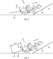
- Fig. 5 schematically illustrates the wheel loader 10 and the pile 42 when the wheel loader 10 drives up onto the pile 42.
- the front wheels are positioned on the pile surface 46 and the rear wheels are positioned on the horizontal surface 44.
- the wheel loader 10 therefore pitches when moving from the Fig. 4 position to the Fig. 5 position relative to the pile 42.
- Fig. 6 schematically illustrates the wheel loader 10 and the pile 42 when the wheel loader 10 drives further up onto the pile 42.
- the wheel loader 10 has pitched further such that the rear detection device 18 detects the horizontal surface 44 as an object 50.
- Fig. 6 shows also shows a distance 52 from the wheel loader 10 to the horizontal surface 44 as measured by the rear detection device 18.
- the wheel loader 10 is pitched 15 degrees relative to the horizontal surface 44.
- the invention disregards such detections when the wheel loader 10 travels forward.
- the invention comprises a determination of whether the wheel loader 10 travels forward or in reverse, e.g. based on the direction information 32 sent from the travel direction sensor 28 to the control system 12. Upon determining that the wheel loader 10 travels forward, the detection event triggered by the detection of the horizontal surface 44 by the rear detection device 18 is ignored. In this way, false positives caused by the horizontal surface 44 can be avoided when driving forward up the pile 42.
- the detection of the horizontal surface 44 can be made based on either of the rear detection information 34 or the distance information 36. In any case, the detection of the horizontal surface 44 by the rear detection device 18 is stored as first detection information, e.g. in the memory 40.
- the position of the working machine 10 may be stored in order to utilize a concept of blocking zones, as described below.
- the position of the wheel loader 10 may be determined by means of the GPS 41a and/or the odometer 41b, and may be stored in the memory 40. In any case, a distance travelled in relation to this position may be monitored.
- the odometer 41b may for example be reset when the object 50 is detected in the detection region 20 by the rear detection device 18 when the wheel loader 10 is traveling forward.
- Fig. 7 schematically illustrates the wheel loader 10 and the pile 42 when the wheel loader 10 drives further up onto the pile 42
- Fig. 8 schematically illustrates the wheel loader 10 and the pile 42 when the wheel loader 10 drives even further up onto the pile 42.
- all wheels are in contact with the pile surface 46.
- the wheel loader 10 is inclined 30 degrees in Fig. 8 .
- the rear wheels are positioned at a junction between the horizontal surface 44 and the pile surface 46.
- the distance 52 as measured by the rear detection device 18 becomes shorter and shorter, despite the wheel loader 10 drives away from the horizontal surface 44. This is due to the successive pitching (counterclockwise in Figs. 6 to 8 ) of the wheel loader 10 from 15 degrees pitch in Fig. 6 to the 30 degrees pitch in Fig. 8 .
- Fig. 9 schematically illustrates the wheel loader 10 and the pile 42 when the wheel loader 10 drives further up onto the pile 42.
- the distance 52 as measured by the rear detection device 18 increases.
- the rear detection information 34 of the horizontal surface 44 as detected by the rear detection device 18 is stored as first detection information.
- Fig. 10 schematically illustrates the wheel loader 10 and the pile 42 when the wheel loader 10 has stopped on the pile 42.
- a blocking zone may be associated with the position of the wheel loader 10 in Fig. 6 (where the object 50 was first detected by the rear detection device 18). Otherwise, the blocking zone may not be set.
- the blocking zone may be represented by one or several positions where the object 50 has been detected by the rear detection device 18 when the wheel loader 10 travels forward. Alternatively, or in addition, the blocking zone may be represented by a distance from one or more of such positions.
- the threshold distance may for example be 10 meters.
- the blocking zone may be wirelessly communicated to a central system.
- a map containing a plurality of such blocking zones can then be created and shared between working machines.
- Fig. 11 schematically illustrates the wheel loader 10 and the pile 42 when the wheel loader 10 travels in reverse from the pile 42 and there is no obstacle behind the wheel loader 10.
- the rear wheels of the wheel loader 10 start to come in contact with the horizontal surface 44.
- the rear detection device 18 detects the horizontal surface 44.
- the horizontal surface 44 is not a true object that needs triggering of a countermeasure.
- the wheel loader 10 backs down there is a need to not trigger the automatic brake all the time.
- the rear detection information 34 of the horizontal surface 44 as detected by the rear detection device 18 is stored as second detection information. From a comparison between Figs. 8 and 11 , it is clear that the second detection information read by the rear detection device 18 in the position of the wheel loader 10 in Fig. 11 corresponds to the first detection information read by the rear detection device 18 in the position of the wheel loader 10 in Fig. 8 . Thus, this event is already triggered. By comparing the first detection information when the wheel loader 10 travels forward up onto the pile 42 with the second detection information when the wheel loader 10 travels in reverse down from the pile 42, it can be concluded that the first detection information and the second detection information represent the same event.
- the detected object 50 is the horizontal surface 44, and not an obstacle that needs triggering of a countermeasure.
- the second detection information is therefore disregarded.
- the first detection information and the second detection information do however not need to be obtained at the exact same position relative to the pile 42.
- a blocking zone has been associated with the Fig. 6 position of the wheel loader 10
- the wheel loader 10 is traveling in reverse and the wheel loader 10 is within the blocking zone.
- the odometer 41b is reset in response to the first detection of the object 50 in the Fig. 6 position.
- the counting by the odometer 41b will decrease. If the wheel loader 10 comes within a threshold blocking distance from the position where the odometer 41b was reset, and the object 50 is detected by the rear detection device 18, it can be determined that the object 50 is the horizontal surface 14 and that no countermeasure should be triggered.
- the threshold blocking distance may for example be 10 meters.
- Fig. 12 schematically illustrates the wheel loader 10 and the pile 42 when the wheel loader 10 travels further in reverse from the pile 42.
- the distance 52 as measured by the rear detection device 18 becomes larger and larger, despite the wheel loader 10 drives towards the horizontal surface 44. This is due to the successive pitching (clockwise in Figs. 11 and 12 ) of the wheel loader 10 when traveling in reverse down from the pile 42.
- the invention exploits this phenomenon by determining that the object 50 as detected by the rear detection device 18 when the distance 52 increases, despite the wheel loader 10 travels in reverse, is the horizontal surface 44.
- a determination that the object 50 detected by the rear detection device 18 is the horizontal surface 44 may however be made in further alternative ways, for example by means of image processing of image data from a camera.
- the rear detection device 18 may be constituted by a camera and the rear detection information 34 may be image data.
- the invention disregards this detection. In this way, false positives generated by the horizontal surface 44 can be avoided also when driving down from the pile 42.
- Fig. 13 schematically illustrates the wheel loader 10 and the pile 42 when the wheel loader 10 travels in reverse from the pile 42.
- an object 54 has appeared behind the wheel loader 10.
- the object 54 is here exemplified as a car.
- the object 54 is a true object. It is therefore desirable to trigger a countermeasure when the object 54 is detected, but not when the horizontal surface 44 is detected.
- the rear detection information 34 of the horizontal surface 44 as detected by the rear detection device 18 is stored as second detection information. From a comparison between Figs. 8 and 13 , it is clear that the second detection information read by the rear detection device 18 in the position of the wheel loader 10 in Fig. 13 does not correspond to the first detection information read by the rear detection device 18 in the position of the wheel loader 10 in Fig. 8 due to the appearance of the object 54.
- the invention therefore causes a countermeasure to be automatically triggered in this case.
- Fig. 14 schematically illustrates the wheel loader 10 and the pile 42 when the wheel loader 10 travels further in reverse from the pile 42 and there is an object 54 behind the wheel loader 10.
- the movement of the wheel loader 10 from the Fig. 11 position to the Fig. 12 position where the distance 52 as measured by the rear detection device 18 increases
- the movement of the wheel loader 10 from the Fig. 13 position to the Fig. 14 position causes the rear detection device 18 to measure a decreasing distance 52.
- a countermeasure is triggered automatically for avoiding collision between the wheel loader 10 and the object 54.
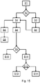
- Fig. 15 is a flowchart outlining general steps of the method according to the invention.
- the method comprises a step S1 of monitoring the detection region 20 behind the wheel loader 10 by means of the rear detection device 18.
- the method further comprises a step S2 of determining whether the wheel loader 10 is traveling forward or in reverse. In case the wheel loader 10 travels forward, the method proceeds to a step S3. In case the wheel loader 10 travels in reverse, the method proceeds to a step S4.
- step S3 the object 50 in the detection region 20 detected by the rear detection device 18 when the wheel loader 10 is traveling forward, is disregarded.
- the method further comprises a step S7, following step S3, of detecting the horizontal surface 44 by the rear detection device 18 as first detection information when traveling with the wheel loader 10 forward from the horizontal surface 44 and onto the pile surface 46.
- step S4 the wheel loader 10 travels in reverse from the pile surface 46 towards or onto the horizontal surface 44. From step S4, the method may proceed to a step S5 or a step S8. Steps S5 and S8 may also be carried out in parallel.
- step S5 the horizontal surface 44 is detected by the rear detection device 18 when the wheel loader 10 travels in reverse towards or onto the horizontal surface 44.
- the method further comprises a step S6, following step S5, of disregarding the detection of the horizontal surface 44 when traveling in reverse towards or onto the horizontal surface 44.
- step S8 the horizontal surface 44 is detected by the rear detection device 18 as second detection information.
- the method further comprises a step S9, following step S8, of determining whether the first detection information corresponds to the second detection information.
- the method proceeds to a step S10. Otherwise, the method proceeds to a step S11.
- step S10 the second detection information is disregarded. That is, no countermeasure is triggered in step S10.
- a countermeasure is automatically triggered.
- the countermeasure is here exemplified as a deceleration of the wheel loader 10.
- the automatic triggering of a countermeasure may be conditional upon a speed of the wheel loader 10 being within a countermeasure speed range of 3 km/h to 15 km/h.
- the method further comprises a step S12 of determining whether a forward gear, a neutral gear or a reverse gear of the wheel loader 10 is active, e.g. by means of the control system 12 based on the gear information 30. In case the reverse gear is active, the method proceeds to a step S13. In case the neutral gear or the forward gear is active, the method proceeds to a step S14. In step S13, the torque transfer through the driveline 22 is interrupted and the wheel loader 10 is braked. In step S14, the wheel loader 10 is braked, e.g. without interrupting the torque transfer through the driveline 22. In any case, the wheel loader 10 may be braked such that the wheel loader 10 comes to a full stop within the detection region 20.
- the method may be tuned by adjusting one or more of the involved parameters.
- examples of such parameters include the height of the rear detection device 18 above the ground, upper and/or lower limit(s) of the countermeasure speed range, size of the detection region 20 etc.
Landscapes
- Engineering & Computer Science (AREA)
- Remote Sensing (AREA)
- Radar, Positioning & Navigation (AREA)
- Structural Engineering (AREA)
- Mining & Mineral Resources (AREA)
- General Engineering & Computer Science (AREA)
- Civil Engineering (AREA)
- Physics & Mathematics (AREA)
- General Physics & Mathematics (AREA)
- Computer Networks & Wireless Communication (AREA)
- Mechanical Engineering (AREA)
- Electromagnetism (AREA)
- Automation & Control Theory (AREA)
- Transportation (AREA)
- Acoustics & Sound (AREA)
- Multimedia (AREA)
- Aviation & Aerospace Engineering (AREA)
- Component Parts Of Construction Machinery (AREA)
Abstract
Description
- The invention relates to a method of controlling a working machine, a control system for controlling a working machine, and a working machine. The invention is applicable to various working machines, such as wheel loaders, dumpers and excavators. Although the invention will be described mainly with respect to a wheel loader, the invention is not restricted to this particular vehicle.
- A wheel loader is usually driven in a so-called short loading cycle. The short loading cycle may be V-shaped or Y-shaped. In the short loading cycle, the wheel loader may be driven forward and reverse in a first direction, change directions, and be driven forward and reverse in a second direction. Each movement segment may be approximately 10 meters. One or both movement segments may also comprise driving up on a pile. The reverse driving is often tricky for the driver. The driver may need to turn his/her head and the view may be obstructed by a hood of the wheel loader. Although there are mirrors, cameras and other system for assisting in rearward driving, it is very difficult to do this task for 8 hours per day and never miss a single obstacle. Reverse driving is also ergonomically bad for the driver when there is a need to turn around to look back.
-
JP 3219005 U - Although some prior art rear detection devices may be useful for detecting an obstacle behind a working machine, the prior art rear detection devices generate false positives during stockpiling when the working machine drives up on a pile with its front wheels and the rear detection device thereby faces down to the ground. Such prior art rear detection devices are therefore not useful for this type of operation with the working machine. A driver is therefore likely to be annoyed in case an alarm is issued frequently without a correct reason, or worse, if the working machine is automatically stopped frequently without a correct reason. Stockpiling is a normal operating mode of the working machine.
- Countermeasures such as alarms and/or automatic braking should not be triggered every time the rear detection device faces down to the ground. It is however desired to utilize the rear detection devices for detecting true obstacles, for example when a human appears behind the working machine.
- An object of the invention is to improve rear detection functionality in a working machine.
- According to a first aspect, the object is achieved by a method of controlling a working machine according to claim 1. The method comprises monitoring a detection region behind the working machine by means of a rear detection device; and determining whether the working machine is traveling forward or in reverse. The method further comprises disregarding an object in the detection region detected by the rear detection device when the working machine is traveling forward.
- When the working machine travels forward from a horizontal surface and onto an inclined surface, the rear detection device may detect the horizontal surface. Since the horizontal surface is not an obstacle that needs to be avoided in this situation, the method can reliably avoid a false positive detection of an object by the rear detection device. The method thereby improves rear detection functionality in the working machine.
- With disregarding the object is meant that no countermeasure for avoiding collision with the object is triggered. Thus, no safety action is taken when the working machine is traveling forward and an object in the detection region is detected by the rear detection device. An object detected by the rear detection device in the detection region may however be used for comparison purposes, as described below.
- The monitored detection region may have a width substantially corresponding to a width of the working machine and a length of approximately 1.5 m to 3 m. This detection region is often hard for the driver to see directly. The detection region may be two-dimensional or three-dimensional.
- The method may be carried out with a working machine of any type as described herein. The determination of whether the working machine is traveling forward or in reverse may be made by means of a travel direction sensor. Since some working machines already comprise a rear detection device and a travel direction sensor, the method can be implemented with little or no hardware modification of the working machine. The travel direction sensor may determine a rotational direction of one or more wheels of the working machine.
- According to one embodiment, the method further comprises traveling with the working machine in reverse towards or onto a base surface from an inclined surface, inclined relative to the base surface; detecting the base surface by means of the rear detection device when traveling in reverse towards or onto the base surface; and disregarding the detection of the base surface when traveling in reverse towards or onto the base surface.
- When the working machine travels in reverse from the inclined surface and towards or onto the base surface, the rear detection device may detect the base surface. The base surface may however already have been detected when driving forward onto the inclined surface. Thus, the detected base surface when driving in reverse is not a new detection event. Since the base surface is not an obstacle that needs to be avoided, the method can reliably avoid a false positive detection of an object by the rear detection device also in this situation. The invention thus avoids false triggering of a previously detected base surface as an obstacle when driving the working machine in reverse down from the inclined surface. The inclined surface may be a pile surface of a pile.
- The working machine and the rear detection device may be configured such that the rear detection device can detect a horizontal surface when the rear wheels of the working machine are positioned on the horizontal surface and a pitch of the working machine is 15 degrees to the horizontal surface, e.g. when its front wheels are positioned on the inclined surface.
- According to one embodiment, the detection of the base surface by means of the rear detection device comprises determining that an object detected by the rear detection device is the base surface when a distance to the object measured by the rear detection device increases when traveling in reverse towards or onto the base surface. This feature is based on the insight that the distance to the base surface increases despite the working machine travels in reverse from the inclined surface towards or onto the base surface. The reason for this is that the pitch of the working machine may change. For example, when the working machine has its front wheels on the inclined surface and its rear wheels on a horizontal surface, the rear detection device may face down to the horizontal surface.
- When the working machine travels in reverse from this position, the working machine becomes more and more aligned with the horizontal surface. This may cause the rear detection device to read an increased distance, despite traveling in reverse, as the working machine adopts the horizontal orientation on the horizontal surface. The working machine thus pitches until the working machine is horizontally oriented on the horizontal surface.
- According to one embodiment, the method further comprises traveling with the working machine forward from the base surface and onto the inclined surface, such that the base surface is detected by the rear detection device as first detection information; traveling with the working machine in reverse from the inclined surface towards or onto the base surface, such that the base surface is detected by the rear detection device as second detection information; and determining whether the first detection information corresponds to the second detection information. In this way, the method can compare the first detection information of the base surface when driving up on the inclined surface with the second detection information when driving down from the inclined surface.
- According to one embodiment, the method further comprises disregarding the second detection information upon determining that the second detection information corresponds to the first detection information. The first detection information can be memorized such that the detection of the base surface a second time when reversing down from the inclined surface does not cause triggering of automatic braking or other countermeasure. In case the second detection information when traveling in reverse does not correspond to the first detection information when traveling forward, it can be concluded that one or more additional objects (in addition to the base surface) has been detected by the rear detection device. In this case, a countermeasure may be needed. The method thereby provides a more reliable collision mitigation.
- According to one embodiment, the method further comprises automatically triggering a countermeasure upon determining that the second detection information does not correspond to the first detection information. The method can thus reliably and correctly detect an obstacle and automatically act on that detection. By means of the countermeasure, a collision between the working machine and a detected object other than the base surface can be avoided, or an impact of such collision can be reduced. In this way, the method improves safety of the working machine.
- According to one variant, the automatic triggering of a countermeasure is conditional upon a speed of the working machine being within a countermeasure speed range. The countermeasure speed range may be at least 2 km/h, such as at least 3 km/h. Alternatively, or in addition, the countermeasure speed range may be less than 20 km/h, such as less than 15 km/h.
- According to one embodiment, the countermeasure comprises decelerating the working machine. Alternatively, or in addition, the countermeasure may comprise issuing an audible or visual alarm. In each case, the countermeasure may be executed for a limited time period, such as 2 s to 3 s. An audible or visual alarm may be issued both interior and exterior of the working machine.
- According to one embodiment, the countermeasure comprises determining whether a forward gear, a neutral gear or a reverse gear of the working machine is active; interrupting a torque transfer through a driveline of the working machine and braking the working machine when the reverse gear is active; and braking the working machine when the neutral gear or the forward gear is active. In case the reverse gear is active, the interruption of the torque transfer through the driveline may comprise switching to the neutral gear. In case the neutral gear or the forward gear is active, the torque transfer through the driveline may not be interrupted.
- In each case, the braking of the working machine may comprise braking with 30 % to 70 %, such as 50 %, of a maximum braking torque of the working machine. Alternatively, or in addition, the braking of the working machine may comprise braking with a braking torque such that the working machine stops within the detection region behind the working machine.
- In order to determine whether the forward gear, the neutral gear or the reverse gear of the working machine is active, the working machine may comprise a gear direction sensor. The gear direction sensor may be distinct from the travel direction sensor. That is, the working machine may travel in reverse with the forward gear (for example when rolling backwards down from a pile), and vice versa.
- According to one embodiment, the method further comprises determining a blocking zone associated with a position of the working machine when detecting an object in the detection region by the rear detection device when the working machine is traveling forward. The working machine may comprise a positioning device for determining the blocking zone. Examples of such positioning device are a GPS (global positioning system) device and an odometer. An odometer has proven to function in this regard, since many work cycles associated with a pile involve substantially straight travel forward and in reverse. However, an odometer in combination with one or more steering angle sensors of the working machine may be used as the positioning device.
- The method may further comprise communicating the blocking zone to a central system, e.g. the cloud. In this way, other working machines can be notified of one or more blocking zones at a worksite. A map containing such blocking zones can thereby be provided.
- According to one example, the determination of the blocking zone is conditional upon that a distance to the detected object is larger than a threshold distance. That is, the blocking zone may be set only when the distance between the working machine and the position where the object was detected increases above the threshold distance.
- According to one embodiment, the detection of the base surface by means of the rear detection device comprises determining that an object detected by the rear detection device is the base surface when the working machine is within the blocking zone. The determination of whether the working machine is within the blocking zone may be made by means of the positioning device. The blocking zone is a zone in which automatic triggering of a countermeasure can be suppressed. In case the countermeasure comprises a braking of the working machine, the blocking zone may thus be referred to as a brake blocking zone.
- According to one embodiment, the inclined surface is inclined 10 degrees to 45 degrees, such as 25 degrees to 35 degrees, relative to the base surface. The inclined surface may be inclined at least 15 degrees relative to the base surface.
- According to one embodiment, the base surface is substantially horizontal, or horizontal. However, the base surface may alternatively be inclined relative to horizontal.
- According to one embodiment, the rear detection device comprises a distance sensor device or a camera device. The distance sensor device may be a sensor configured to emit and detect reflection of electromagnetic waves. The distance sensor device may for example be a radar, a lidar, an infrared sensor or an ultrasonic sensor. One example of a suitable radar is a continuous-wave frequency-modulated (CWFM) radar. The camera device may be a single camera or a stereo camera.
- According to one embodiment, the working machine is a loader.
- The invention also relates to a control system for controlling a working machine having a rear detection device arranged to monitor a detection region behind the working machine. The control system comprises at least one data processing device and at least one memory having a computer program stored thereon. The computer program comprises program code which, when executed by the at least one data processing device, causes the at least one data processing device to perform the steps of receiving rear detection information from the rear detection device; and receiving direction information indicative of whether the working machine is traveling forward or in reverse. The computer program comprises program code which, when executed by the at least one data processing device, causes the at least one data processing device to perform the step of disregarding rear detection information indicative of an object in the detection region when the working machine is traveling forward. The computer program may further comprise program code which, when executed by the at least one data processing device, causes the at least one data processing device to perform, or command performance of, any step as described herein.
- According to one embodiment, the computer program comprises program code which, when executed by the at least one data processing device, causes the at least one data processing device to perform the steps of determining whether the direction information is indicative of the working machine is traveling in reverse; determining whether the rear detection information is indicative of a base surface when the working machine is traveling in reverse towards or onto the base surface from an inclined surface, inclined relative to the base surface; and disregarding the rear detection information indicative of the base surface when traveling in reverse towards or onto the base surface.
- According to one embodiment, the computer program comprises program code which, when executed by the at least one data processing device, causes the at least one data processing device to perform the steps of receiving distance information from the rear detection device indicative of a distance to an object in the detection region; and determining that the object is the base surface when the distance increases when traveling in reverse to towards or onto the base surface.
- According to one embodiment, the computer program comprises program code which, when executed by the at least one data processing device, causes the at least one data processing device to perform the steps of receiving rear detection information indicative of the base surface as first detection information when traveling forward from the base surface and onto the inclined surface; receiving rear detection information indicative of the base surface as second detection information when traveling in reverse from the inclined surface towards or onto the base surface; and determining whether the first detection information corresponds to the second detection information.
- According to one embodiment, the computer program comprises program code which, when executed by the at least one data processing device, causes the at least one data processing device to perform the step of disregarding the second detection information upon determining that the second detection information corresponds to the first detection information.
- According to one embodiment, the computer program comprises program code which, when executed by the at least one data processing device, causes the at least one data processing device to perform the step of automatically triggering a countermeasure upon determining that the second detection information does not correspond to the first detection information.
- According to one embodiment, the countermeasure comprises commanding deceleration of the working machine.
- According to one embodiment, the computer program comprises program code which, when executed by the at least one data processing device, causes the at least one data processing device to perform the steps of receiving gear information indicative of whether a forward gear, a neutral gear or a reverse gear of the working machine is active; commanding interruption of a torque transfer through a driveline of the working machine and commanding braking of the working machine when the reverse gear is active; and commanding braking of the working machine when the neutral gear or the forward gear is active.
- According to one embodiment, the computer program comprises program code which, when executed by the at least one data processing device, causes the at least one data processing device to perform the step of determining a blocking zone associated with a position of the working machine when detecting an object in the detection region by the rear detection device when the working machine is traveling forward.
- According to one embodiment, the computer program comprises program code which, when executed by the at least one data processing device, causes the at least one data processing device to perform the step of determining that an object detected by the rear detection device is the base surface when the working machine is within the blocking zone.
- According to one embodiment, the inclined surface is inclined 10 degrees to 45 degrees relative to the base surface.
- According to one embodiment, the base surface is substantially horizontal.
- The invention also relates to a working machine. The working machine comprises a control system according to the invention. The working machine may be of any type as described herein.
- According to one embodiment, the working machine further comprises the rear detection device. The rear detection device may for example be positioned at a height between 0.3 m to 1.5 m.
- According to one embodiment, the working machine is a loader, such as a wheel loader. The working machine alternatively be a dumper or an excavator.
- Further advantages and advantageous features of the invention are disclosed in the following description and in the dependent claims.
- With reference to the appended drawings, below follows a more detailed description of embodiments of the invention cited as examples.
- In the drawings:
-
Fig. 1 schematically illustrates a side view of a wheel loader; -
Fig. 2 schematically illustrates a block diagram of the wheel loader; -
Fig. 3 schematically illustrates the wheel loader and a pile when the wheel loader drives towards the pile; -
Fig. 4 schematically illustrates the wheel loader and the pile when the wheel loader has reached the pile; -
Fig. 5 schematically illustrates the wheel loader and the pile when the wheel loader drives up onto the pile; -
Fig. 6 schematically illustrates the wheel loader and the pile when the wheel loader drives further up onto the pile; -
Fig. 7 schematically illustrates the wheel loader and the pile when the wheel loader drives further up onto the pile; -
Fig. 8 schematically illustrates the wheel loader and the pile when the wheel loader drives further up onto the pile; -
Fig. 9 schematically illustrates the wheel loader and the pile when the wheel loader drives further up onto the pile; -
Fig. 10 schematically illustrates the wheel loader and the pile when the wheel loader has stopped on the pile; -
Fig. 11 schematically illustrates the wheel loader and the pile when the wheel loader travels in reverse from the pile and there is no obstacle behind the wheel loader; -
Fig. 12 schematically illustrates the wheel loader and the pile when the wheel loader travels further in reverse from the pile and there is no obstacle behind the wheel loader; -
Fig. 13 schematically illustrates the wheel loader and the pile when the wheel loader travels in reverse from the pile and there is an obstacle behind the wheel loader; -
Fig. 14 schematically illustrates the wheel loader and the pile when the wheel loader travels further in reverse from the pile and there is an obstacle behind the wheel loader; and -
Fig. 15 is a flowchart outlining the general steps of the method according to the invention. - In the following, a method of controlling a working machine, a control system for controlling a working machine, and a working machine, will be described. The same reference numerals will be used to denote the same or similar structural features.
-
Fig. 1 schematically illustrates a side view of awheel loader 10. Thewheel loader 10 is one example of a working machine according to the invention. Thewheel loader 10 comprises acontrol system 12. Thewheel loader 10 of this example comprises fourwheels 14 and abucket 16. - The
wheel loader 10 further comprises arear detection device 18. By means of therear detection device 18, adetection region 20 behind thewheel loader 10 can be monitored. Therear detection device 18 may for example be positioned at a height of 0.3 m to 1.5 m above the ground. Thedetection region 20 may for example extend 2.5 m behind thewheel loader 10. -
Fig. 2 schematically illustrates a block diagram of thewheel loader 10. In addition to thecontrol system 12, therear detection device 18 and thewheels 14, thewheel loader 10 of this example further comprises adriveline 22, agearshift lever 24, agear direction sensor 26 and atravel direction sensor 28. - The
gearshift lever 24 of this example can be manually put in a forward gear, a neutral gear or a reverse gear. Thegear direction sensor 26 is arranged to detect whether the forward gear, the neutral gear or the reverse gear is currently applied. Thegear direction sensor 26 is further configured to sendgear information 30 to thecontrol system 12 containing information regarding the position of thegearshift lever 24. - The
travel direction sensor 28 is arranged to determine whether thewheel loader 10 is traveling forward or in reverse. To this end, thetravel direction sensor 28 of this specific example monitors a rotational direction of at least one of thewheels 14. Thetravel direction sensor 28 is further configured to senddirection information 32 to thecontrol system 12 containing information regarding the travel direction of thewheel loader 10. - The
rear detection device 18 is here a distance sensor device that can measure a distance to an object behind thewheel loader 10. Therear detection device 18 is configured to obtainrear detection information 34 anddistance information 36 from thedetection region 20 and to send therear detection information 34 and thedistance information 36 to thecontrol system 12. Although therear detection information 34 and thedistance information 36 are illustrated as two signals, thedistance information 36 may alternatively be extracted from therear detection information 34. - The
rear detection device 18 of this specific example is a continuous-wave frequency-modulated (CWFM) radar, but a wide range of alternative rear detection devices may be used instead. Therear detection device 18 may also comprise a passive infrared (PIR) sensor. A PIR sensor can detect heated objects in thedetection region 20 behind thewheel loader 10. - In case the
rear detection device 18 is a camera, an object in thedetection region 20 behind thewheel loader 10 can be detected by means of video looming or deep learning. Video looming may comprise concluding that an object approaches when its size on an image increases. Video looming only requires a single camera. By means of deep learning, an algorithm can be trained to identify objects of interest, e.g. humans. - As a further example of a
rear detection device 18, therear detection device 18 comprises a stereo camera. A stereo camera is capable of capturing three-dimensional images. - The
control system 12 comprises adata processing device 38 and amemory 40. Thememory 40 has a computer program stored thereon. The computer program comprises program code which, when executed by thedata processing device 38, causes thedata processing device 38 to perform, or command performance of, various steps as described herein. - The
wheel loader 10 of this example further comprises aGPS 41a and anodometer 41b. Each of theGPS 41a and theodometer 41b is in signal communication with thecontrol system 12. TheGPS 41a and theodometer 41b are examples of a positioning device according to the invention. -
Fig. 3 schematically illustrates thewheel loader 10 and apile 42 when thewheel loader 10 drives towards thepile 42. Thewheel loader 10 drives on ahorizontal surface 44 and thepile 42 comprises apile surface 46. Thehorizontal surface 44 and thepile surface 46 are examples of a base surface and an inclined surface, respectively, according to the invention. InFig. 3 , anangle 48 between thepile surface 46 and thehorizontal surface 44 is 30 degrees, which is a typical angle of piles of various materials. Therear detection device 18 monitors thedetection region 20 behind thewheel loader 10. -
Fig. 4 schematically illustrates thewheel loader 10 and thepile 42 when thewheel loader 10 has reached thepile 42, andFig. 5 schematically illustrates thewheel loader 10 and thepile 42 when thewheel loader 10 drives up onto thepile 42. InFig. 5 , the front wheels are positioned on thepile surface 46 and the rear wheels are positioned on thehorizontal surface 44. Thewheel loader 10 therefore pitches when moving from theFig. 4 position to theFig. 5 position relative to thepile 42. -
Fig. 6 schematically illustrates thewheel loader 10 and thepile 42 when thewheel loader 10 drives further up onto thepile 42. InFig. 6 , thewheel loader 10 has pitched further such that therear detection device 18 detects thehorizontal surface 44 as anobject 50.Fig. 6 shows also shows adistance 52 from thewheel loader 10 to thehorizontal surface 44 as measured by therear detection device 18. InFig. 6 , thewheel loader 10 is pitched 15 degrees relative to thehorizontal surface 44. - In the position of the
wheel loader 10 inFig. 6 when thewheel loader 10 travels forward up on thepile 42, thehorizontal surface 44 detected by therear detection device 18 is not an obstacle that should cause any countermeasure. In order to avoid this from happening, the invention disregards such detections when thewheel loader 10 travels forward. The invention comprises a determination of whether thewheel loader 10 travels forward or in reverse, e.g. based on thedirection information 32 sent from thetravel direction sensor 28 to thecontrol system 12. Upon determining that thewheel loader 10 travels forward, the detection event triggered by the detection of thehorizontal surface 44 by therear detection device 18 is ignored. In this way, false positives caused by thehorizontal surface 44 can be avoided when driving forward up thepile 42. - The detection of the
horizontal surface 44 can be made based on either of therear detection information 34 or thedistance information 36. In any case, the detection of thehorizontal surface 44 by therear detection device 18 is stored as first detection information, e.g. in thememory 40. - When the
object 50 is detected by therear detection device 18 and thewheel loader 10 travels forward, the position of the workingmachine 10 may be stored in order to utilize a concept of blocking zones, as described below. The position of thewheel loader 10 may be determined by means of theGPS 41a and/or theodometer 41b, and may be stored in thememory 40. In any case, a distance travelled in relation to this position may be monitored. Theodometer 41b may for example be reset when theobject 50 is detected in thedetection region 20 by therear detection device 18 when thewheel loader 10 is traveling forward. -
Fig. 7 schematically illustrates thewheel loader 10 and thepile 42 when thewheel loader 10 drives further up onto thepile 42, andFig. 8 schematically illustrates thewheel loader 10 and thepile 42 when thewheel loader 10 drives even further up onto thepile 42. In the position of thewheel loader 10 inFig. 8 , all wheels are in contact with thepile surface 46. Thus, thewheel loader 10 is inclined 30 degrees inFig. 8 . The rear wheels are positioned at a junction between thehorizontal surface 44 and thepile surface 46. - As illustrated in
Figs. 6 ,7 and 8 , thedistance 52 as measured by therear detection device 18 becomes shorter and shorter, despite thewheel loader 10 drives away from thehorizontal surface 44. This is due to the successive pitching (counterclockwise inFigs. 6 to 8 ) of thewheel loader 10 from 15 degrees pitch inFig. 6 to the 30 degrees pitch inFig. 8 . -
Fig. 9 schematically illustrates thewheel loader 10 and thepile 42 when thewheel loader 10 drives further up onto thepile 42. When thewheel loader 10 drives forward from theFig. 8 position to theFig. 9 position, thedistance 52, as measured by therear detection device 18 increases. Also in each of the positions of thewheel loader 10 according toFigs. 7, 8 and9 , therear detection information 34 of thehorizontal surface 44 as detected by therear detection device 18 is stored as first detection information. -
Fig. 10 schematically illustrates thewheel loader 10 and thepile 42 when thewheel loader 10 has stopped on thepile 42. When thewheel loader 10 drives forward from theFig. 9 position to theFig. 10 position, thedistance 52, as measured by therear detection device 18 increases further. When thewheel loader 10 has reached the position on thepile 42 according toFig. 10 , thewheel loader 10 dumps its load onto thepile 42 by means of thebucket 16. - When the
wheel loader 10 has travelled a distance from theFig. 6 position that is larger than a threshold distance, a blocking zone may be associated with the position of thewheel loader 10 inFig. 6 (where theobject 50 was first detected by the rear detection device 18). Otherwise, the blocking zone may not be set. The blocking zone may be represented by one or several positions where theobject 50 has been detected by therear detection device 18 when thewheel loader 10 travels forward. Alternatively, or in addition, the blocking zone may be represented by a distance from one or more of such positions. The threshold distance may for example be 10 meters. - The blocking zone may be wirelessly communicated to a central system. A map containing a plurality of such blocking zones can then be created and shared between working machines.
-
Fig. 11 schematically illustrates thewheel loader 10 and thepile 42 when thewheel loader 10 travels in reverse from thepile 42 and there is no obstacle behind thewheel loader 10. InFig. 11 , the rear wheels of thewheel loader 10 start to come in contact with thehorizontal surface 44. As shown inFig. 11 , therear detection device 18 detects thehorizontal surface 44. However, thehorizontal surface 44 is not a true object that needs triggering of a countermeasure. When thewheel loader 10 backs down, there is a need to not trigger the automatic brake all the time. - Since the
wheel loader 10 now travels in reverse, therear detection information 34 of thehorizontal surface 44 as detected by therear detection device 18 is stored as second detection information. From a comparison betweenFigs. 8 and11 , it is clear that the second detection information read by therear detection device 18 in the position of thewheel loader 10 inFig. 11 corresponds to the first detection information read by therear detection device 18 in the position of thewheel loader 10 inFig. 8 . Thus, this event is already triggered. By comparing the first detection information when thewheel loader 10 travels forward up onto thepile 42 with the second detection information when thewheel loader 10 travels in reverse down from thepile 42, it can be concluded that the first detection information and the second detection information represent the same event. Based on this conclusion, it can be determined that the detectedobject 50 is thehorizontal surface 44, and not an obstacle that needs triggering of a countermeasure. The second detection information is therefore disregarded. The first detection information and the second detection information do however not need to be obtained at the exact same position relative to thepile 42. - In case a blocking zone has been associated with the
Fig. 6 position of thewheel loader 10, no countermeasure is triggered when theobject 50 is detected by therear detection device 18, thewheel loader 10 is traveling in reverse and thewheel loader 10 is within the blocking zone. For example, let's say theodometer 41b is reset in response to the first detection of theobject 50 in theFig. 6 position. When driving in reverse, the counting by theodometer 41b will decrease. If thewheel loader 10 comes within a threshold blocking distance from the position where theodometer 41b was reset, and theobject 50 is detected by therear detection device 18, it can be determined that theobject 50 is thehorizontal surface 14 and that no countermeasure should be triggered. The threshold blocking distance may for example be 10 meters. -
Fig. 12 schematically illustrates thewheel loader 10 and thepile 42 when thewheel loader 10 travels further in reverse from thepile 42. As illustrated inFigs. 11 and 12 , thedistance 52 as measured by therear detection device 18 becomes larger and larger, despite thewheel loader 10 drives towards thehorizontal surface 44. This is due to the successive pitching (clockwise inFigs. 11 and 12 ) of thewheel loader 10 when traveling in reverse down from thepile 42. The invention exploits this phenomenon by determining that theobject 50 as detected by therear detection device 18 when thedistance 52 increases, despite thewheel loader 10 travels in reverse, is thehorizontal surface 44. - A determination that the
object 50 detected by therear detection device 18 is thehorizontal surface 44 may however be made in further alternative ways, for example by means of image processing of image data from a camera. Thus, therear detection device 18 may be constituted by a camera and therear detection information 34 may be image data. - In any case, when the
object 50 behind thewheel loader 10, as detected by therear detection device 18 when driving in reverse down from thepile 42, is thehorizontal surface 44, the invention disregards this detection. In this way, false positives generated by thehorizontal surface 44 can be avoided also when driving down from thepile 42. -
Fig. 13 schematically illustrates thewheel loader 10 and thepile 42 when thewheel loader 10 travels in reverse from thepile 42. InFig. 13 , anobject 54 has appeared behind thewheel loader 10. Theobject 54 is here exemplified as a car. In contrast to thehorizontal surface 44, theobject 54 is a true object. It is therefore desirable to trigger a countermeasure when theobject 54 is detected, but not when thehorizontal surface 44 is detected. - Since the
wheel loader 10 now travels in reverse, therear detection information 34 of thehorizontal surface 44 as detected by therear detection device 18 is stored as second detection information. From a comparison betweenFigs. 8 and13 , it is clear that the second detection information read by therear detection device 18 in the position of thewheel loader 10 inFig. 13 does not correspond to the first detection information read by therear detection device 18 in the position of thewheel loader 10 inFig. 8 due to the appearance of theobject 54. The invention therefore causes a countermeasure to be automatically triggered in this case. -
Fig. 14 schematically illustrates thewheel loader 10 and thepile 42 when thewheel loader 10 travels further in reverse from thepile 42 and there is anobject 54 behind thewheel loader 10. In contrast to the movement of thewheel loader 10 from theFig. 11 position to theFig. 12 position, where thedistance 52 as measured by therear detection device 18 increases, the movement of thewheel loader 10 from theFig. 13 position to theFig. 14 position causes therear detection device 18 to measure a decreasingdistance 52. In response to this detection, a countermeasure is triggered automatically for avoiding collision between thewheel loader 10 and theobject 54. -
Fig. 15 is a flowchart outlining general steps of the method according to the invention. The method comprises a step S1 of monitoring thedetection region 20 behind thewheel loader 10 by means of therear detection device 18. - The method further comprises a step S2 of determining whether the
wheel loader 10 is traveling forward or in reverse. In case thewheel loader 10 travels forward, the method proceeds to a step S3. In case thewheel loader 10 travels in reverse, the method proceeds to a step S4. - In step S3, the
object 50 in thedetection region 20 detected by therear detection device 18 when thewheel loader 10 is traveling forward, is disregarded. - The method further comprises a step S7, following step S3, of detecting the
horizontal surface 44 by therear detection device 18 as first detection information when traveling with thewheel loader 10 forward from thehorizontal surface 44 and onto thepile surface 46. - In step S4, the
wheel loader 10 travels in reverse from thepile surface 46 towards or onto thehorizontal surface 44. From step S4, the method may proceed to a step S5 or a step S8. Steps S5 and S8 may also be carried out in parallel. - In step S5, the
horizontal surface 44 is detected by therear detection device 18 when thewheel loader 10 travels in reverse towards or onto thehorizontal surface 44. - The method further comprises a step S6, following step S5, of disregarding the detection of the
horizontal surface 44 when traveling in reverse towards or onto thehorizontal surface 44. - In step S8, the
horizontal surface 44 is detected by therear detection device 18 as second detection information. - The method further comprises a step S9, following step S8, of determining whether the first detection information corresponds to the second detection information.
- If the first detection information corresponds to the second detection information, the method proceeds to a step S10. Otherwise, the method proceeds to a step S11.
- In step S10, the second detection information is disregarded. That is, no countermeasure is triggered in step S10.
- In step S11, a countermeasure is automatically triggered. The countermeasure is here exemplified as a deceleration of the
wheel loader 10. The automatic triggering of a countermeasure may be conditional upon a speed of thewheel loader 10 being within a countermeasure speed range of 3 km/h to 15 km/h. - The method further comprises a step S12 of determining whether a forward gear, a neutral gear or a reverse gear of the
wheel loader 10 is active, e.g. by means of thecontrol system 12 based on thegear information 30. In case the reverse gear is active, the method proceeds to a step S13. In case the neutral gear or the forward gear is active, the method proceeds to a step S14. In step S13, the torque transfer through thedriveline 22 is interrupted and thewheel loader 10 is braked. In step S14, thewheel loader 10 is braked, e.g. without interrupting the torque transfer through thedriveline 22. In any case, thewheel loader 10 may be braked such that thewheel loader 10 comes to a full stop within thedetection region 20. - The method may be tuned by adjusting one or more of the involved parameters. Examples of such parameters include the height of the
rear detection device 18 above the ground, upper and/or lower limit(s) of the countermeasure speed range, size of thedetection region 20 etc. - It is to be understood that the present invention is not limited to the embodiments described above and illustrated in the drawings; rather, the skilled person will recognize that many changes and modifications may be made within the scope of the appended claims.
Claims (29)
- A method of controlling a working machine (10), the method comprising:- monitoring (S1) a detection region (20) behind the working machine (10) by means of a rear detection device (18); and- determining (S2) whether the working machine (10) is traveling forward or in reverse; characterized in that the method further comprises:- disregarding (S3) an object (50) in the detection region (20) detected by the rear detection device (18) when the working machine (10) is traveling forward.
- The method according to claim 1, further comprising:- traveling (S4) with the working machine (10) in reverse towards or onto a base surface (44) from an inclined surface (46), inclined relative to the base surface (44);- detecting (S5) the base surface (44) by means of the rear detection device (18) when traveling in reverse towards or onto the base surface (44); and- disregarding (S6) the detection of the base surface (44) when traveling in reverse towards or onto the base surface (44).
- The method according to claim 2, wherein the detection (S5) of the base surface (44) by means of the rear detection device (18) comprises:- determining that an object (50) detected by the rear detection device (18) is the base surface (44) when a distance (52) to the object (50) measured by the rear detection device (18) increases when traveling in reverse towards or onto the base surface (44).
- The method according to claim 2 or 3, further comprising:- traveling (S7) with the working machine (10) forward from the base surface (44) and onto the inclined surface (46), such that the base surface (44) is detected by the rear detection device (18) as first detection information;- traveling (S4) with the working machine (10) in reverse from the inclined surface (46) towards or onto the base surface (44), such that the base surface (44) is detected (S8) by the rear detection device (18) as second detection information; and- determining (S9) whether the first detection information corresponds to the second detection information.
- The method according to claim 4, further comprising:- disregarding (S10) the second detection information upon determining (S9) that the second detection information corresponds to the first detection information.
- The method according to claim 4 or 5, further comprising:- automatically triggering (S11) a countermeasure upon determining that the second detection information does not correspond to the first detection information.
- The method according to claim 6, wherein the countermeasure comprises decelerating the working machine (10).
- The method according to claim 6 or 7, wherein the countermeasure comprises:- determining (S12) whether a forward gear, a neutral gear or a reverse gear of the working machine (10) is active;- interrupting (S13) a torque transfer through a driveline (22) of the working machine (10) and braking the working machine (10) when the reverse gear is active; and- braking (S14) the working machine (10) when the neutral gear or the forward gear is active.
- The method according to any of claims 2 to 8, further comprising:- determining a blocking zone associated with a position of the working machine (10) when detecting an object (50) in the detection region (20) by the rear detection device (18) when the working machine (10) is traveling forward.
- The method according to claim 9, wherein the detection (S5) of the base surface (44) by means of the rear detection device (18) comprises:- determining that an object (50) detected by the rear detection device (18) is the base surface (44) when the working machine (10) is within the blocking zone.
- The method according to any of claims 2 to 10, wherein the inclined surface (46) is inclined 10 degrees to 45 degrees relative to the base surface (44).
- The method according to any claims 2 to 11 wherein the base surface (44) is substantially horizontal.
- The method according to any of the preceding claims, wherein the rear detection device (18) comprises a distance sensor device or a camera device.
- The method according to any of the preceding claims, wherein the working machine (10) is a loader.
- A control system (12) for controlling a working machine (10) having a rear detection device (18) arranged to monitor a detection region (20) behind the working machine (10), the control system (12) comprising at least one data processing device (38) and at least one memory (40) having a computer program stored thereon, the computer program comprising program code which, when executed by the at least one data processing device (38), causes the at least one data processing device (38) to perform the steps of:- receiving rear detection information (34) from the rear detection device (18); and- receiving direction information (32) indicative of whether the working machine (10) is traveling forward or in reverse;characterized in that the computer program comprises program code which, when executed by the at least one data processing device (38), causes the at least one data processing device (38) to perform the step of:- disregarding rear detection information (34) indicative of an object (50) in the detection region (20) when the working machine (10) is traveling forward.
- The control system (12) according to claim 15, wherein the computer program comprises program code which, when executed by the at least one data processing device (38), causes the at least one data processing device (38) to perform the steps of:- determining whether the direction information (32) is indicative of the working machine (10) is traveling in reverse;- determining whether the rear detection information (34) is indicative of a base surface (44) when the working machine (10) is traveling in reverse towards or onto the base surface (44) from an inclined surface (46), inclined relative to the base surface (44); and- disregarding the rear detection information (34) indicative of the base surface (44) when traveling in reverse towards or onto the base surface (44).
- The control system (12) according to claim 16, wherein the computer program comprises program code which, when executed by the at least one data processing device (38), causes the at least one data processing device (38) to perform the steps of:- receiving distance information (36) from the rear detection device (18) indicative of a distance (52) to an object (50) in the detection region (20); and- determining that the object (50) is the base surface (44) when the distance (52) increases when traveling in reverse to towards or onto the base surface (44).
- The control system (12) according to claim 16 or 17, wherein the computer program comprises program code which, when executed by the at least one data processing device (38), causes the at least one data processing device (38) to perform the steps of:- receiving rear detection information (34) indicative of the base surface (44) as first detection information when traveling forward from the base surface (44) and onto the inclined surface (46);- receiving rear detection information (34) indicative of the base surface (44) as second detection information when traveling in reverse from the inclined surface (46) towards or onto the base surface (44); and- determining whether the first detection information corresponds to the second detection information.
- The control system (12) according to claim 18, wherein the computer program comprises program code which, when executed by the at least one data processing device (38), causes the at least one data processing device (38) to perform the step of:- disregarding the second detection information upon determining that the second detection information corresponds to the first detection information.
- The control system (12) according to claim 19, wherein the computer program comprises program code which, when executed by the at least one data processing device (38), causes the at least one data processing device (38) to perform the step of:- automatically triggering a countermeasure upon determining that the second detection information does not correspond to the first detection information.
- The control system (12) according to claim 20, wherein the countermeasure comprises commanding deceleration of the working machine (10).
- The control system (12) according to claim 20 or 21, wherein the computer program comprises program code which, when executed by the at least one data processing device (38), causes the at least one data processing device (38) to perform the steps of:- receiving gear information (30) indicative of whether a forward gear, a neutral gear or a reverse gear of the working machine (10) is active;- commanding interruption of a torque transfer through a driveline (22) of the working machine (10) and commanding braking of the working machine (10) when the reverse gear is active; and- commanding braking of the working machine (10) when the neutral gear or the forward gear is active.
- The control system (12) according to any of claims 16 to 22, wherein the computer program comprises program code which, when executed by the at least one data processing device (38), causes the at least one data processing device (38) to perform the step of:- determining a blocking zone associated with a position of the working machine (10) when detecting an object (50) in the detection region (20) by the rear detection device (18) when the working machine (10) is traveling forward.
- The control system (12) according to claim 23, wherein the computer program comprises program code which, when executed by the at least one data processing device (38), causes the at least one data processing device (38) to perform the step of:- determining that an object (50) detected by the rear detection device (18) is the base surface (44) when the working machine (10) is within the blocking zone.
- The control system (12) according to any of claims 16 to 24, wherein the inclined surface (46) is inclined 10 degrees to 45 degrees relative to the base surface (44).
- The control system (12) according to any of claims 16 to 25, wherein the base surface (44) is substantially horizontal.
- A working machine (10) comprising a control system (12) according to any of claims 15 to 26.
- The working machine (10) according to claim 27, further comprising the rear detection device (18).
- The working machine (10) according to claim 27 or 28, wherein the working machine (10) is a loader.
Priority Applications (3)
| Application Number | Priority Date | Filing Date | Title |
|---|---|---|---|
| EP20212366.7A EP4012118A1 (en) | 2020-12-08 | 2020-12-08 | Method of controlling working machine, control system and working machine |
| CN202111469113.2A CN114658048B (en) | 2020-12-08 | 2021-12-03 | Method for controlling work machine, control system and work machine |
| US17/544,624 US12077947B2 (en) | 2020-12-08 | 2021-12-07 | Method of controlling working machine, control system and working machine |
Applications Claiming Priority (1)
| Application Number | Priority Date | Filing Date | Title |
|---|---|---|---|
| EP20212366.7A EP4012118A1 (en) | 2020-12-08 | 2020-12-08 | Method of controlling working machine, control system and working machine |
Publications (1)
| Publication Number | Publication Date |
|---|---|
| EP4012118A1 true EP4012118A1 (en) | 2022-06-15 |
Family
ID=73747899
Family Applications (1)
| Application Number | Title | Priority Date | Filing Date |
|---|---|---|---|
| EP20212366.7A Pending EP4012118A1 (en) | 2020-12-08 | 2020-12-08 | Method of controlling working machine, control system and working machine |
Country Status (3)
| Country | Link |
|---|---|
| US (1) | US12077947B2 (en) |
| EP (1) | EP4012118A1 (en) |
| CN (1) | CN114658048B (en) |
Families Citing this family (3)
| Publication number | Priority date | Publication date | Assignee | Title |
|---|---|---|---|---|
| KR102510867B1 (en) * | 2018-01-31 | 2023-03-16 | 현대두산인프라코어 주식회사 | Brake contorl apparatus and brake control method for construction machinery |
| US11724693B2 (en) * | 2021-02-09 | 2023-08-15 | Ford Global Technologies, Llc | Systems and methods to prevent vehicular mishaps |
| US20230272599A1 (en) * | 2022-02-28 | 2023-08-31 | Caterpillar Inc. | Work machine safety zone control |
Citations (5)
| Publication number | Priority date | Publication date | Assignee | Title |
|---|---|---|---|---|
| JP3219005U (en) | 2018-09-10 | 2018-11-22 | 大成ロテック株式会社 | Construction vehicle |
| WO2019168122A1 (en) * | 2018-02-28 | 2019-09-06 | 住友建機株式会社 | Excavator |
| WO2020066228A1 (en) * | 2018-09-28 | 2020-04-02 | 株式会社小松製作所 | Work vehicle surroundings monitoring system and work vehicle surroundings monitoring method |
| US20200319346A1 (en) * | 2019-04-03 | 2020-10-08 | Caterpillar Inc. | Avoidance modifier system for collision avoidance system |
| FR3095392A1 (en) * | 2019-04-24 | 2020-10-30 | Option Automatismes | Anti-collision system for construction machinery, and construction machinery equipped with such an anti-collision system |
Family Cites Families (10)
| Publication number | Priority date | Publication date | Assignee | Title |
|---|---|---|---|---|
| JPH0735862A (en) * | 1993-07-20 | 1995-02-07 | Komatsu Ltd | Obstacle detection device for traveling vehicle |
| JP6267972B2 (en) * | 2014-01-23 | 2018-01-24 | 日立建機株式会社 | Work machine ambient monitoring device |
| US9841768B2 (en) * | 2014-03-28 | 2017-12-12 | Yanmar Co., Ltd. | Autonomous travelling service vehicle |
| DE102016109850B4 (en) | 2016-05-30 | 2024-01-11 | Valeo Schalter Und Sensoren Gmbh | Method for detecting an inclination in a roadway of a motor vehicle, driver assistance system and motor vehicle |
| US20180105107A1 (en) * | 2016-10-19 | 2018-04-19 | Novateur Research Solutions LLC | Pedestrian collision warning system for vehicles |
| JP7089954B2 (en) * | 2017-06-30 | 2022-06-23 | 酒井重工業株式会社 | Obstacle detector for construction vehicles |
| JP7122101B2 (en) * | 2017-11-07 | 2022-08-19 | 株式会社Subaru | Vehicle obstacle detection device |
| JP2019214824A (en) * | 2018-06-11 | 2019-12-19 | 株式会社フジタ | Working machine |
| US10627516B2 (en) | 2018-07-19 | 2020-04-21 | Luminar Technologies, Inc. | Adjustable pulse characteristics for ground detection in lidar systems |
| WO2021066019A1 (en) * | 2019-09-30 | 2021-04-08 | 株式会社小松製作所 | Work machine and control method for work machine |
-
2020
- 2020-12-08 EP EP20212366.7A patent/EP4012118A1/en active Pending
-
2021
- 2021-12-03 CN CN202111469113.2A patent/CN114658048B/en active Active
- 2021-12-07 US US17/544,624 patent/US12077947B2/en active Active
Patent Citations (5)
| Publication number | Priority date | Publication date | Assignee | Title |
|---|---|---|---|---|
| WO2019168122A1 (en) * | 2018-02-28 | 2019-09-06 | 住友建機株式会社 | Excavator |
| JP3219005U (en) | 2018-09-10 | 2018-11-22 | 大成ロテック株式会社 | Construction vehicle |
| WO2020066228A1 (en) * | 2018-09-28 | 2020-04-02 | 株式会社小松製作所 | Work vehicle surroundings monitoring system and work vehicle surroundings monitoring method |
| US20200319346A1 (en) * | 2019-04-03 | 2020-10-08 | Caterpillar Inc. | Avoidance modifier system for collision avoidance system |
| FR3095392A1 (en) * | 2019-04-24 | 2020-10-30 | Option Automatismes | Anti-collision system for construction machinery, and construction machinery equipped with such an anti-collision system |
Also Published As
| Publication number | Publication date |
|---|---|
| CN114658048B (en) | 2024-06-21 |
| US12077947B2 (en) | 2024-09-03 |
| CN114658048A (en) | 2022-06-24 |
| US20220178112A1 (en) | 2022-06-09 |
Similar Documents
| Publication | Publication Date | Title |
|---|---|---|
| US12077947B2 (en) | Method of controlling working machine, control system and working machine | |
| US11926316B2 (en) | Collision avoidance assist apparatus | |
| EP3572590B1 (en) | Work machine | |
| US5585798A (en) | Obstacle detection system for automotive vehicle | |
| US9390624B2 (en) | Vehicle-installation intersection judgment apparatus and program | |
| CN101678819B (en) | Collision reducing device | |
| US6819991B2 (en) | Vehicle sensing based pre-crash threat assessment system | |
| EP2302412B1 (en) | System and method for evaluation of an automotive vehicle forward collision threat | |
| US7613568B2 (en) | Crash-safe vehicle control system | |
| US20160202351A1 (en) | Obstacle detection device for work machine | |
| US8005616B2 (en) | Method for determining relevant objects | |
| US20060282218A1 (en) | Vehicle travel safety apparatus | |
| US20030097237A1 (en) | Monitor system of vehicle outside and the method thereof | |
| JP7122101B2 (en) | Vehicle obstacle detection device | |
| US8184018B2 (en) | Image-based vehicle safety warning system | |
| US20180194346A1 (en) | Vehicle Backup Assistance System | |
| US5684697A (en) | Driver emulative vehicle control system | |
| EP4032761B1 (en) | Rear collision traffic assist brake system of vehicle and control method thereof | |
| KR102682768B1 (en) | Rear Safety System of Construction Equipment | |
| CN116985786A (en) | Vehicle speed control method and system and automobile | |
| JP4878870B2 (en) | Road shape estimation device, obstacle detection device, and road shape estimation method | |
| EP4015326A1 (en) | Vehicle control system, vehicle and method | |
| US20070005213A1 (en) | Backward control for automobiles using telematics and method thereof | |
| JP7740888B2 (en) | Surroundings monitoring device, surroundings monitoring method, and surroundings monitoring program | |
| KR102761201B1 (en) | Smart construction heavy equipment collision prevention system using radar and thermal sensing |
Legal Events
| Date | Code | Title | Description |
|---|---|---|---|
| PUAI | Public reference made under article 153(3) epc to a published international application that has entered the european phase |
Free format text: ORIGINAL CODE: 0009012 |
|
| STAA | Information on the status of an ep patent application or granted ep patent |
Free format text: STATUS: THE APPLICATION HAS BEEN PUBLISHED |
|
| AK | Designated contracting states |
Kind code of ref document: A1 Designated state(s): AL AT BE BG CH CY CZ DE DK EE ES FI FR GB GR HR HU IE IS IT LI LT LU LV MC MK MT NL NO PL PT RO RS SE SI SK SM TR |
|
| STAA | Information on the status of an ep patent application or granted ep patent |
Free format text: STATUS: REQUEST FOR EXAMINATION WAS MADE |
|
| 17P | Request for examination filed |
Effective date: 20221124 |
|
| RBV | Designated contracting states (corrected) |
Designated state(s): AL AT BE BG CH CY CZ DE DK EE ES FI FR GB GR HR HU IE IS IT LI LT LU LV MC MK MT NL NO PL PT RO RS SE SI SK SM TR |
|
| STAA | Information on the status of an ep patent application or granted ep patent |
Free format text: STATUS: EXAMINATION IS IN PROGRESS |
|
| 17Q | First examination report despatched |
Effective date: 20230217 |