EP4011810A1 - Continuous ore feeding device - Google Patents
Continuous ore feeding device Download PDFInfo
- Publication number
- EP4011810A1 EP4011810A1 EP20851566.8A EP20851566A EP4011810A1 EP 4011810 A1 EP4011810 A1 EP 4011810A1 EP 20851566 A EP20851566 A EP 20851566A EP 4011810 A1 EP4011810 A1 EP 4011810A1
- Authority
- EP
- European Patent Office
- Prior art keywords
- pressure
- concentrate
- tank
- adjusting
- lift
- Prior art date
- Legal status (The legal status is an assumption and is not a legal conclusion. Google has not performed a legal analysis and makes no representation as to the accuracy of the status listed.)
- Pending
Links
- 239000012141 concentrate Substances 0.000 claims abstract description 176
- 238000003723 Smelting Methods 0.000 claims abstract description 39
- 238000009423 ventilation Methods 0.000 claims description 10
- 238000007599 discharging Methods 0.000 claims description 3
- 230000032258 transport Effects 0.000 description 7
- 239000007789 gas Substances 0.000 description 6
- 230000003628 erosive effect Effects 0.000 description 4
- 230000008018 melting Effects 0.000 description 4
- 238000002844 melting Methods 0.000 description 4
- 239000002184 metal Substances 0.000 description 4
- 230000007423 decrease Effects 0.000 description 3
- 238000010586 diagram Methods 0.000 description 3
- CWYNVVGOOAEACU-UHFFFAOYSA-N Fe2+ Chemical compound [Fe+2] CWYNVVGOOAEACU-UHFFFAOYSA-N 0.000 description 2
- QVGXLLKOCUKJST-UHFFFAOYSA-N atomic oxygen Chemical compound [O] QVGXLLKOCUKJST-UHFFFAOYSA-N 0.000 description 2
- 239000000463 material Substances 0.000 description 2
- 238000005259 measurement Methods 0.000 description 2
- 238000005065 mining Methods 0.000 description 2
- 239000001301 oxygen Substances 0.000 description 2
- 229910052760 oxygen Inorganic materials 0.000 description 2
- 230000000694 effects Effects 0.000 description 1
- 239000008187 granular material Substances 0.000 description 1
- 238000010438 heat treatment Methods 0.000 description 1
- 239000011819 refractory material Substances 0.000 description 1
- 238000011144 upstream manufacturing Methods 0.000 description 1
Images

Classifications
-
- F—MECHANICAL ENGINEERING; LIGHTING; HEATING; WEAPONS; BLASTING
- F27—FURNACES; KILNS; OVENS; RETORTS
- F27D—DETAILS OR ACCESSORIES OF FURNACES, KILNS, OVENS OR RETORTS, IN SO FAR AS THEY ARE OF KINDS OCCURRING IN MORE THAN ONE KIND OF FURNACE
- F27D3/00—Charging; Discharging; Manipulation of charge
- F27D3/18—Charging particulate material using a fluid carrier
-
- F—MECHANICAL ENGINEERING; LIGHTING; HEATING; WEAPONS; BLASTING
- F27—FURNACES; KILNS; OVENS; RETORTS
- F27D—DETAILS OR ACCESSORIES OF FURNACES, KILNS, OVENS OR RETORTS, IN SO FAR AS THEY ARE OF KINDS OCCURRING IN MORE THAN ONE KIND OF FURNACE
- F27D3/00—Charging; Discharging; Manipulation of charge
- F27D3/0033—Charging; Discharging; Manipulation of charge charging of particulate material
-
- B—PERFORMING OPERATIONS; TRANSPORTING
- B65—CONVEYING; PACKING; STORING; HANDLING THIN OR FILAMENTARY MATERIAL
- B65G—TRANSPORT OR STORAGE DEVICES, e.g. CONVEYORS FOR LOADING OR TIPPING, SHOP CONVEYOR SYSTEMS OR PNEUMATIC TUBE CONVEYORS
- B65G53/00—Conveying materials in bulk through troughs, pipes or tubes by floating the materials or by flow of gas, liquid or foam
- B65G53/04—Conveying materials in bulk pneumatically through pipes or tubes; Air slides
-
- B—PERFORMING OPERATIONS; TRANSPORTING
- B65—CONVEYING; PACKING; STORING; HANDLING THIN OR FILAMENTARY MATERIAL
- B65G—TRANSPORT OR STORAGE DEVICES, e.g. CONVEYORS FOR LOADING OR TIPPING, SHOP CONVEYOR SYSTEMS OR PNEUMATIC TUBE CONVEYORS
- B65G53/00—Conveying materials in bulk through troughs, pipes or tubes by floating the materials or by flow of gas, liquid or foam
- B65G53/34—Details
- B65G53/40—Feeding or discharging devices
- B65G53/46—Gates or sluices, e.g. rotary wheels
-
- B—PERFORMING OPERATIONS; TRANSPORTING
- B65—CONVEYING; PACKING; STORING; HANDLING THIN OR FILAMENTARY MATERIAL
- B65G—TRANSPORT OR STORAGE DEVICES, e.g. CONVEYORS FOR LOADING OR TIPPING, SHOP CONVEYOR SYSTEMS OR PNEUMATIC TUBE CONVEYORS
- B65G53/00—Conveying materials in bulk through troughs, pipes or tubes by floating the materials or by flow of gas, liquid or foam
- B65G53/34—Details
- B65G53/40—Feeding or discharging devices
- B65G53/46—Gates or sluices, e.g. rotary wheels
- B65G53/4691—Gates or sluices, e.g. rotary wheels of air-lock type, i.e. at least two valves opening asynchronously
-
- B—PERFORMING OPERATIONS; TRANSPORTING
- B65—CONVEYING; PACKING; STORING; HANDLING THIN OR FILAMENTARY MATERIAL
- B65G—TRANSPORT OR STORAGE DEVICES, e.g. CONVEYORS FOR LOADING OR TIPPING, SHOP CONVEYOR SYSTEMS OR PNEUMATIC TUBE CONVEYORS
- B65G53/00—Conveying materials in bulk through troughs, pipes or tubes by floating the materials or by flow of gas, liquid or foam
- B65G53/34—Details
- B65G53/66—Use of indicator or control devices, e.g. for controlling gas pressure, for controlling proportions of material and gas, for indicating or preventing jamming of material
-
- F—MECHANICAL ENGINEERING; LIGHTING; HEATING; WEAPONS; BLASTING
- F27—FURNACES; KILNS; OVENS; RETORTS
- F27B—FURNACES, KILNS, OVENS OR RETORTS IN GENERAL; OPEN SINTERING OR LIKE APPARATUS
- F27B3/00—Hearth-type furnaces, e.g. of reverberatory type; Electric arc furnaces ; Tank furnaces
- F27B3/10—Details, accessories or equipment, e.g. dust-collectors, specially adapted for hearth-type furnaces
- F27B3/18—Arrangements of devices for charging
-
- F—MECHANICAL ENGINEERING; LIGHTING; HEATING; WEAPONS; BLASTING
- F27—FURNACES; KILNS; OVENS; RETORTS
- F27D—DETAILS OR ACCESSORIES OF FURNACES, KILNS, OVENS OR RETORTS, IN SO FAR AS THEY ARE OF KINDS OCCURRING IN MORE THAN ONE KIND OF FURNACE
- F27D19/00—Arrangements of controlling devices
-
- F—MECHANICAL ENGINEERING; LIGHTING; HEATING; WEAPONS; BLASTING
- F27—FURNACES; KILNS; OVENS; RETORTS
- F27D—DETAILS OR ACCESSORIES OF FURNACES, KILNS, OVENS OR RETORTS, IN SO FAR AS THEY ARE OF KINDS OCCURRING IN MORE THAN ONE KIND OF FURNACE
- F27D3/00—Charging; Discharging; Manipulation of charge
- F27D3/0025—Charging or loading melting furnaces with material in the solid state
- F27D3/0026—Introducing additives into the melt
-
- B—PERFORMING OPERATIONS; TRANSPORTING
- B65—CONVEYING; PACKING; STORING; HANDLING THIN OR FILAMENTARY MATERIAL
- B65G—TRANSPORT OR STORAGE DEVICES, e.g. CONVEYORS FOR LOADING OR TIPPING, SHOP CONVEYOR SYSTEMS OR PNEUMATIC TUBE CONVEYORS
- B65G2201/00—Indexing codes relating to handling devices, e.g. conveyors, characterised by the type of product or load being conveyed or handled
- B65G2201/04—Bulk
- B65G2201/045—Sand, soil and mineral ore
-
- B—PERFORMING OPERATIONS; TRANSPORTING
- B65—CONVEYING; PACKING; STORING; HANDLING THIN OR FILAMENTARY MATERIAL
- B65G—TRANSPORT OR STORAGE DEVICES, e.g. CONVEYORS FOR LOADING OR TIPPING, SHOP CONVEYOR SYSTEMS OR PNEUMATIC TUBE CONVEYORS
- B65G2812/00—Indexing codes relating to the kind or type of conveyors
- B65G2812/16—Pneumatic conveyors
- B65G2812/1608—Pneumatic conveyors for bulk material
- B65G2812/1616—Common means for pneumatic conveyors
- B65G2812/1625—Feeding or discharging means
-
- B—PERFORMING OPERATIONS; TRANSPORTING
- B65—CONVEYING; PACKING; STORING; HANDLING THIN OR FILAMENTARY MATERIAL
- B65G—TRANSPORT OR STORAGE DEVICES, e.g. CONVEYORS FOR LOADING OR TIPPING, SHOP CONVEYOR SYSTEMS OR PNEUMATIC TUBE CONVEYORS
- B65G2812/00—Indexing codes relating to the kind or type of conveyors
- B65G2812/16—Pneumatic conveyors
- B65G2812/1608—Pneumatic conveyors for bulk material
- B65G2812/1641—Air pressure systems
-
- F—MECHANICAL ENGINEERING; LIGHTING; HEATING; WEAPONS; BLASTING
- F27—FURNACES; KILNS; OVENS; RETORTS
- F27D—DETAILS OR ACCESSORIES OF FURNACES, KILNS, OVENS OR RETORTS, IN SO FAR AS THEY ARE OF KINDS OCCURRING IN MORE THAN ONE KIND OF FURNACE
- F27D19/00—Arrangements of controlling devices
- F27D2019/0028—Regulation
- F27D2019/0075—Regulation of the charge quantity
-
- Y—GENERAL TAGGING OF NEW TECHNOLOGICAL DEVELOPMENTS; GENERAL TAGGING OF CROSS-SECTIONAL TECHNOLOGIES SPANNING OVER SEVERAL SECTIONS OF THE IPC; TECHNICAL SUBJECTS COVERED BY FORMER USPC CROSS-REFERENCE ART COLLECTIONS [XRACs] AND DIGESTS
- Y02—TECHNOLOGIES OR APPLICATIONS FOR MITIGATION OR ADAPTATION AGAINST CLIMATE CHANGE
- Y02P—CLIMATE CHANGE MITIGATION TECHNOLOGIES IN THE PRODUCTION OR PROCESSING OF GOODS
- Y02P10/00—Technologies related to metal processing
- Y02P10/20—Recycling
Definitions
- the present invention relates to a continuous concentrate feeding equipment capable of continuously supplying granular concentrate to a smelting furnace without interruption even when a granular material is received in non-ferrous smelting or the like.
- an concentrate supply device described in Patent Literature 1 is known as a device that supplies granular concentrate to a smelting furnace.
- This device includes a service tank that temporarily stores powdery concentrate carried in by a flow conveyor or the like and a lift tank located below the service tank, and has a structure in which the concentrate accumulated in the service tank is fed into the lift tank, and when a certain amount of concentrate is accumulated in the lift tank, compressed air is introduced into the lift tank to feed the concentrate in the tank to the smelting furnace together with the compressed air and the concentrate is blown into a bath through a lance in the furnace.
- the tip of the lance is located on the melting bath in the smelting furnace, heating proceeds when the concentrate, which acts as a cold material for the lance, is not transported. This causes the melting loss of the tip part of the lance, and it is necessary to replenish a lance of a predetermined length on a regular basis. Additionally, erosion of a refractory constituting the smelting furnace by a molten metal bath is an important factor for determining the life of the furnace body, and the higher the bath temperature, the shorter the life of the furnace body.
- erosion of a hearth refractory directly under the lance and a side wall refractory in the vicinity of a molten metal bath interface is a major factor in determining the furnace repair cycle of the smelting furnace.
- An exhaust gas generated from the smelting furnace needs to be suctioned by an exhaust gas treatment facility in the subsequent stage such that the draft in the furnace is always kept at negative pressure. For this reason, it is necessary to excessively suction the exhaust gas by the amount of the fluctuation of the draft.
- Patent Literature 1 Japanese Unexamined Patent Application, First Publication No. Hei 5-272875
- the present invention has been made in view of the above circumstances, and an object thereof is to provide a continuous concentrate feeding equipment capable of continuously supplying concentrate to an concentrate smelting furnace even when the concentrate is received in a lift tank.
- the present invention adopts the following means.
- the air passage may include a first air passage for introducing the compressed air into the pressure-adjusting tank and a second air passage for introducing the compressed air into the lift tank, a pressure-adjusting ventilation passage may be provided to allow the pressure-adjusting tank and the lift tank to communicate with each other, the pressure-adjusting tank may be provided with pressure-adjusting tank control means for temporarily releasing an internal pressure of the pressure-adjusting tank to receive the concentrate, introducing the compressed air after the reception to raise the internal pressure of the pressure-adjusting tank to be higher than an internal pressure of the lift tank, and discharging the concentrate to the lift tank, and the lift tank may be provided with lift tank control means for introducing the compressed air into the lift tank continuously throughout the reception and discharge of the concentrate into and from the lift tank.
- the pressure-adjusting tank control means may include a pressure gauge and a metering gauge that are installed in the pressure-adjusting tank, an opening and closing valve that is provided in an concentrate reception passage of the pressure-adjusting tank, an opening and closing valve that is provided in an concentrate discharge passage that couples the pressure-adjusting tank to the lift tank, a pressure-adjusting valve that is provided in the first air passage, and a pressure-adjusting valve that is provided in the pressure-adjusting ventilation passage that couples the pressure-adjusting tank to the lift tank
- the lift tank control means may include a pressure gauge and a metering gauge that are installed in the lift tank, a pressure-adjusting valve that is provided in the second air passage, and a supply valve that is provided in an concentrate supply passage that couples the lift tank to the smelting furnace.
- the continuous concentrate feeding equipment may further include a flow conveyor that supplies the concentrate to the pressure-adjusting tank; and an opening and closing valve that is provided in an concentrate reception passage that couples the flow conveyor to the pressure-adjusting tank.
- the present invention it is possible to provide a continuous concentrate feeding equipment capable of continuously supplying the concentrate to the concentrate smelting furnace even when the concentrate is received in the lift tank.
- Fig. 1 is a block diagram illustrating main functions of a continuous concentrate feeding equipment 100 according to an embodiment of the present invention.
- the continuous concentrate feeding equipment 100 mainly includes a pressure-adjusting tank 50, a lift tank 51, an air passage 54, and pressure control means 55.
- the air passage 54 includes a first air passage 56 for introducing compressed air into the pressure-adjusting tank 50 and a second air passage 57 for introducing compressed air into the lift tank 51.
- a pressure-adjusting ventilation passage that allows the two passages to communicate with each other is provided between the pressure-adjusting tank 50 and the lift tank 51.
- the pressure control means 55 includes first pressure control means (pressure-adjusting tank control means) 60 that controls the compressed air to be introduced into the pressure-adjusting tank 50 and adjusts the internal pressure of the pressure-adjusting tank 50, and second pressure control means (lift tank control means) 70 that controls the compressed air to be introduced into the lift tank 51 and adjusts the internal pressure of the lift tank 51.
- the pressure control means 55 may further include a device that automatically controls the functions (outputs) of the first pressure control means 60 and the second pressure control means 70 so that the internal pressure difference between the pressure-adjusting tank 50 and the lift tank 51 is maintained within a predetermined range.
- the first pressure control means 60 temporarily releases the internal pressure of the pressure-adjusting tank 50 to receive the concentrate, introduces the compressed air after the reception, raises the internal pressure of the pressure-adjusting tank to be higher than the internal pressure of the lift tank 51, and discharges the concentrate to the lift tank 51.
- the second pressure control means 70 introduces compressed air into the lift tank 51 continuously throughout the reception and discharge of the concentrate into and from the lift tank 51.
- the pressure-adjusting tank 50 is means (device) for temporarily accumulating granular concentrate supplied from the outside at a predetermined pressure.
- a first air passage 56 for introducing compressed air for pressure control is connected to the pressure-adjusting tank 50.
- the first air passage 56 is provided with a pressure-adjusting valve C that adjusts the amount of compressed air introduced.
- the first pressure control means 60 is connected to the pressure-adjusting tank 50. By using the first pressure control means 60, it is possible to control the amount of compressed air to be introduced, the timing of introduction, and the like and adjust the internal pressure of the pressure-adjusting tank 50.
- the first pressure control means 60 mainly includes a pressure gauge A and a metering gauge B installed in the pressure-adjusting tank 50, an opening and closing valve F provided in an concentrate reception passage 61 of the pressure-adjusting tank 50, an opening and closing valve G provided in an concentrate discharge passage 62 that couples the pressure-adjusting tank 50 to the lift tank 51, a pressure-adjusting valve C provided in the first air passage 56, and pressure-adjusting valves D and E provided in a pressure-adjusting ventilation passage 58 that couples the pressure-adjusting tank 50 to the lift tank 51.
- An exhaust line for releasing the internal pressure is connected to the pressure-adjusting tank 50, and an exhaust valve 53 is provided in this exhaust line. Additionally, the concentrate reception passage 61 is connected to an upper part of the pressure-adjusting tank 50, and the concentrate reception passage 61 is provided with an opening and closing valve F for receiving the granular concentrate.
- the opening and closing operations for the exhaust valve 53, the opening and closing valve F, the pressure-adjusting valve C of the first air passage, the opening and closing valve G of the concentrate discharge passage, and the pressure-adjusting valve D and the pressure-adjusting valve E of the pressure-adjusting ventilation passage are performed such that the pressure in the pressure-adjusting tank 50 is adjusted to a predetermined pressure on the basis of on signals of measurement results of the pressure gauge A and the metering gauge B.
- the opening and closing operations at this time may be manually performed or may be automated using a computer or the like.
- the lift tank 51 is means (device) for temporarily accumulating the concentrate received from the pressure-adjusting tank 50 at a pressure smaller than the pressure adjusted by the pressure-adjusting tank 50 and discharging the concentrate to the smelting furnace at a predetermined timing.
- the second air passage 57 for introducing the compressed air for pressure control and the compressed air for concentrate transportation are connected to the lift tank 51.
- the second air passage 57 is provided with a pressure-adjusting valve J for adjusting the amount of compressed air introduced.
- the second pressure control means 70 for introducing compressed air into the lift tank 51 to adjust the pressure is connected to the lift tank 51.
- the second pressure control means 70 mainly includes the pressure gauge H and the metering gauge I installed in the lift tank 51, the pressure-adjusting valve J provided in the second air passage 57, and a supply valve K provided in the concentrate supply passage 59 that couples the lift tank 51 and the smelting furnace 52.
- the concentrate supply passage 59 is provided with a supply valve K that adjusts the amount of concentrate supplied to the smelting furnace together with the compressed air discharged from the lift tank 51.
- the opening and closing operations for the opening and closing valve G, the pressure-adjusting valve J, and the supply valve K are performed such that the pressure inside the lift tank 51 becomes a predetermined pressure on the basis of the signals of the measurement results of the pressure gauge H and the metering gauge I.
- the opening and closing operations at this time may be manually performed or may be automated using a computer or the like.
- the continuous concentrate feeding equipment 100 further includes a flow conveyor 80 as means for carrying in the granular concentrate.
- the amount of concentrate carried into the pressure-adjusting tank 50 can be adjusted by the opening and closing operation of the opening and closing valve F.
- the exhaust valve 53 is opened and the inside of the pressure-adjusting tank 50 becomes atmospheric pressure, and the concentrate conveyed by the flow conveyor 80 is supplied to the pressure-adjusting tank 50 via the opening and closing valve F.
- the opening and closing valve G that couples the pressure-adjusting tank 50 to the lift tank 51 is closed.
- the pressure-adjusting valve C is opened, compressed air is introduced into the pressure-adjusting tank 50 through the first air passage 56, and the internal pressure of the pressure-adjusting tank 50 is set to be slightly higher than the internal pressure of the lift tank 51.
- the opening and closing valve G is opened, and the concentrate is supplied to the lift tank 51 through the concentrate discharge passage.
- the lift tank 51 When the lift tank 51 receives the concentrate from the pressure-adjusting tank 50, it is necessary to discharge air having a volume comparable to the amount of the concentrate received from the tank.
- the concentrate When the concentrate is discharged from the pressure-adjusting tank 50 to the lift tank 51, the concentrate of the pressure-adjusting tank 50 is easily discharged to the lift tank 51 by opening the pressure-adjusting valves D and E in the pressure-adjusting ventilation passage to allow the internal air of the lift tank 51 to escape to the pressure-adjusting tank 50.
- the pressure-adjusting valve J of the second air passage 57 is opened to introduce compressed air, and the amount of the compressed air introduced is such that the internal pressure of the lift tank 51 is kept at a certain pressure equal to or higher than the atmospheric pressure by the pressure gauge H.
- the supply valve K of the concentrate supply passage 59 is opened, the concentrate is discharged from the lift tank 51 together with the compressed air, and is fed into the smelting furnace 52 through the concentrate supply passage. In this way, the concentrate is fed into the smelting furnace 52 from the lift tank 51 while the concentrate is being fed from the pressure-adjusting tank 50 to the lift tank 51.
- the flow rate of the concentrate can be controlled by adjusting the opening and closing of the pressure-adjusting valve J through the lift tank control means 70.
- the amount of concentrate in the lift tank 51 is detected by the metering gauge I, and when the amount of the concentrate decreases to be equal to or less than a reference, the opening and closing valve G is opened through the pressure-adjusting tank control means 60, the concentrate is supplied from the pressure-adjusting tank 50 through the discharge passage to the lift tank 51, and the amount of concentrate in the lift tank 51 is maintained to be equal to or more than a certain amount while the concentrate is conveyed to the smelting furnace 52.
- the lift tank 51 can continuously supply the concentrate to the smelting furnace 52 while receiving the concentrate.
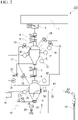
- Fig. 2 is a plan view schematically illustrating a configuration example of a continuous concentrate feeding equipment 110 corresponding to the block diagram of Fig. 1 .
- the pressure-adjusting tank 2 is provided below the flow conveyor 1, and a damper 3, a charging source valve 4, and a charging valve 5 are provided in the concentrate reception passage that connects the flow conveyor 1 to the pressure-adjusting tank 2.
- the damper 3, the charging source valve 4, and the charging valve 5 correspond to the opening and closing valve F in Fig. 1 .
- the pressure-adjusting tank 2 is provided with limit switches 12 and 32, which detect the amount of concentrate, and a load cell 13.
- the limit switches 12 and 32 and the load cell 13 correspond to the metering gauge B in Fig. 1 .
- the pressure-adjusting tank 2 is provided with a larger exhaust valve 29 and a smaller exhaust valve 31.
- the larger exhaust valve 29 and the smaller exhaust valve 31 correspond to the exhaust valve 53 in Fig. 1 .
- the pressure-adjusting tank 2 is provided with a compressed air supply passage 14, the compressed air supply passage 14 is connected to a compressor (not illustrated), and a pipeline of the compressed air supply passage 14 leading to the pressure-adjusting tank 2 is provided with a pressurizing valve 33.
- the pipeline of the supply passage 14 leading to the pressure-adjusting tank 2 corresponds to the first air passage of Fig. 1
- the pressurizing valve 33 corresponds to the pressure-adjusting valve C.
- a lift tank 6 is provided below the pressure-adjusting tank 2, and a charging source valve 7 and a charging valve 8 are provided in an concentrate discharge passage that connects the pressure-adjusting tank 2 to the lift tank 6.
- the charging source valve 7 and the charging valve 8 correspond to the opening and closing valve G in Fig. 1 .
- the compressed air supply passage 14 is branched and connected to the lift tank 6.
- the supply passage 14 connected to the lift tank 6 corresponds to the second air passage 57 in Fig. 1 .
- a pressure-equalizing pipe 17 including pressure equalizing valves 15 and 16 is connected to the pressure-adjusting tank 2 and the lift tank 6, and pressure gauges 19 and 20 and pressure setters 21 and 22 are provided in the tanks 2 and 6, respectively.
- the pressure equalizing valves 15 and 16 correspond to the pressure-adjusting valves D and E in Fig. 1 , respectively, and the pressure-equalizing pipe 17 corresponds to the ventilation passage.
- the pressure gauges 19 and 20 correspond to the pressure gauges A and H in Fig. 1 , respectively.
- An air supply pipe 9 and an concentrate supply passage 11 for transporting concentrate are connected to a lower part of the lift tank 6.
- the air supply pipe 9 is integrated with the compressed air supply passage 14 and connected to the compressor (not illustrated).
- the tip of the concentrate supply passage 11 is coupled to a lance 10.
- the concentrate in the lift tank 6 is sent from the lift tank 6 through the concentrate supply passage 11 and the lance 10 to the smelting furnace by the compressed air introduced through the air supply pipe 9.
- the lift tank 6 is provided with a load cell 23 that detects the amount of concentrate charged.
- the load cell 23 corresponds to the metering gauge I in Fig. 1 .
- the concentrate supply passage 11 is provided with a transport valve 24, and the concentrate supply passage 11 communicates with the lift tank 6 via the transport valve 24.
- the concentrate supply passage 11 is provided with a branch passage 25, and a booster valve 26 and a flow rate setter 27 are connected in series to the branch passage 25.
- a pressurizing valve 30 is provided in the pipeline of the compressed air supply passage 14 leading to the lift tank 6.
- the air supply pipes 9, the concentrate supply passages 11, and the compressed air supply passages 14 correspond to the second air passages in Fig. 1 .
- the booster valve 26 and the pressurizing valve 30 correspond to the pressure-adjusting valve J in Fig. 1 .
- the transport valve 24 corresponds to the supply valve K.
- the pressure setters 21 and 22 and the flow rate setter 27 are connected to a control device 28. Electric signals indicating the amounts of concentrate and the tank pressures in the pressure-adjusting tank 2 and the lift tank 6 are respectively input to the control device 28, and a control system similar to the pressure-adjusting tank control means 60 illustrated in Fig. 1 for the pressure-adjusting tank 2 is formed by respective devices corresponding to the pressure gauge A, the metering gauge B, the pressure-adjusting valve C, D, and E, and the opening and closing valves F and G that are illustrated in Fig. 1 .
- a control system similar to the lift tank control means 70 illustrated in Fig. 1 for the lift tank 6 is formed by the above devices corresponding to the pressure gauge H, the metering gauge I, the pressure-adjusting valve J, and the supply valve K illustrated in Fig. 1 .
- the pressure setting value and the flow rate setting value of the lift tank 6 are changed on the basis of the electric signals such that the concentrate amount of the lift tank 6 becomes a set amount till the next concentrate reception of the lift tank 6.
- the pressurizing valve 30 is opened to raise the internal force of the lift tank 6. After that, after the internal pressure of the lift tank 6 reaches the pressure set by the pressure setter 22, the pressurizing valve 30 is closed to stop the pressurization. After that, the booster valve 26 and the transport valve 24 are opened, and the concentrate of the lift tank 6 is transported toward the lance 10 by compressed air through the concentrate supply passage 11 (transportation step).
- the pressurizing valve 33 is opened to pressurize the pressure-adjusting tank 2 until the pressure of the lift tank 6 measured by the pressure gauge 20 and the pressure difference set in advance by the control device 28, for example, the pressure of the pressure-adjusting tank 2 become slightly higher than the pressure of the lift tank 6 (pressurization step).
- the charging valve 8, the charging source valve 7, and the pressure equalizing valves 15 and 16 are opened, and the concentrate is charged from the pressure-adjusting tank 2 into the lift tank 6 (charging step). Therefore, the lift tank 6 can transport the concentrate while receiving the concentrate without requiring the lift tank exhaust step as in the related-art device.
- the pressure equalizing valves 15, 16, the charging valve 8, and the charging source valve 7 are closed to stop the charging of the concentrate (loading stop step).
- the pressure-adjusting tank 50 capable of adjusting the tank internal pressure is provided upstream of the lift tank 51 instead of the related-art service tank. For that reason, when the concentrate is received, the internal pressure of the pressure-adjusting tank can be temporarily released to receive the concentrate. After the reception, the internal pressure of the pressure-adjusting tank can be made slightly higher than the internal pressure of the lift tank 51 to feed the concentrate to the lift tank 51. Therefore, when the lift tank 51 receives the concentrate, it is not necessary to release the internal pressure of the lift tank 51 to the atmospheric pressure, and the lift tank 51 can continuously supply the concentrate to the smelting furnace while receiving the concentrate. Accordingly, the mining rate can be increased from the related-art 40% to 70% to 100%.
- the concentrate is continuously supplied to the smelting furnace 52 while the lift tank 51 receives the concentrate. For that reason, the balance between the amount of concentrate and the amount of oxygen, which are blown into the smelting furnace 52, is always maintained, and the temperature fluctuation in a molten metal bath and the draft fluctuation in the smelting furnace 52 can be reduced. Therefore, it is possible to reduce the excessive suction amount of the exhaust gas, increase the amount of concentrate conveyed to the smelting furnace 52, and suppress the melting loss of the lance and the erosion of refractories such as a hearth and a furnace side wall.
Landscapes
- Engineering & Computer Science (AREA)
- Mechanical Engineering (AREA)
- General Engineering & Computer Science (AREA)
- Manufacture And Refinement Of Metals (AREA)
- Furnace Charging Or Discharging (AREA)
- Air Transport Of Granular Materials (AREA)
- Filling Or Emptying Of Bunkers, Hoppers, And Tanks (AREA)
Abstract
Description
- The present invention relates to a continuous concentrate feeding equipment capable of continuously supplying granular concentrate to a smelting furnace without interruption even when a granular material is received in non-ferrous smelting or the like.
- Priority is claimed on
Japanese Patent Application No. 2019-147581, filed August 9, 2019 - In non-ferrous smelting and the like, an concentrate supply device described in Patent Literature 1 is known as a device that supplies granular concentrate to a smelting furnace. This device includes a service tank that temporarily stores powdery concentrate carried in by a flow conveyor or the like and a lift tank located below the service tank, and has a structure in which the concentrate accumulated in the service tank is fed into the lift tank, and when a certain amount of concentrate is accumulated in the lift tank, compressed air is introduced into the lift tank to feed the concentrate in the tank to the smelting furnace together with the compressed air and the concentrate is blown into a bath through a lance in the furnace.
- In such a device, when the concentrate is fed into the lift tank from the service tank, it is necessary to release the internal pressure of the lift tank to the atmospheric pressure such that the concentrate is received in the lift tank. Therefore, since the compressed air for transporting the concentrate introduced into the lift tank must be temporarily stopped and the conveyance of the concentrate sent to the smelting furnace is interrupted, the concentrate cannot be continuously supplied and the concentrate is conveyed in batches into the furnace.
- In this way, since the supply of concentrate to the lift tank and the conveyance of concentrate from the lift tank to the smelting furnace are repeated for each batch, the percentage of the time required for processing one batch to the time for concentrate to be transported (hereinafter, mining rate) remains at about 40% to 70%, which is inefficient. Since the lift tank transports concentrate at an upper limit of the instantaneous conveyance capacity, a batch operation cannot completely eliminate the time needed to stop the conveyance and it is difficult to increase the amount of concentrate transported to the smelting furnace any further. Additionally, in the short term, it is difficult to balance the amount of concentrate transported into the furnace and the amount of oxygen blown into the furnace, which causes fluctuations in the bath temperature and draft in the smelting furnace.
- Since the tip of the lance is located on the melting bath in the smelting furnace, heating proceeds when the concentrate, which acts as a cold material for the lance, is not transported. This causes the melting loss of the tip part of the lance, and it is necessary to replenish a lance of a predetermined length on a regular basis. Additionally, erosion of a refractory constituting the smelting furnace by a molten metal bath is an important factor for determining the life of the furnace body, and the higher the bath temperature, the shorter the life of the furnace body. In particular, erosion of a hearth refractory directly under the lance and a side wall refractory in the vicinity of a molten metal bath interface is a major factor in determining the furnace repair cycle of the smelting furnace. An exhaust gas generated from the smelting furnace needs to be suctioned by an exhaust gas treatment facility in the subsequent stage such that the draft in the furnace is always kept at negative pressure. For this reason, it is necessary to excessively suction the exhaust gas by the amount of the fluctuation of the draft.
- [Patent Literature 1]
Japanese Unexamined Patent Application, First Publication No. Hei 5-272875 - As described above, in the related-art concentrate supply device, it is difficult to increase the amount of concentrate supplied to the smelting furnace because the supply of concentrate to the smelting furnace is intermittent. In addition, there are problems that it is necessary to excessively suction the exhaust gas generated from the smelting furnace in an exhaust gas treatment facility in the subsequent stage and melting loss of the tip part of the lance and erosion of the refractory in the vicinity of the molten metal bath interface in the furnace proceed.
- The present invention has been made in view of the above circumstances, and an object thereof is to provide a continuous concentrate feeding equipment capable of continuously supplying concentrate to an concentrate smelting furnace even when the concentrate is received in a lift tank.
- In order to solve the above problems, the present invention adopts the following means.
-
- [1] A continuous concentrate feeding equipment according to one aspect of the present invention includes a pressure-adjusting tank that temporarily accumulates granular concentrate; a lift tank that receives the concentrate from the pressure-adjusting tank and discharges the concentrate to a smelting furnace; an air passage for introducing compressed air into the pressure-adjusting tank and the lift tank, respectively; and pressure control means for controlling the introduction of the compressed air, and the concentrate is continuously supplied from the lift tank even when the lift tank receives the concentrate from the pressure-adjusting tank by the pressure control means.
- The term "accumulating concentrate" in the present specification shall include the case of "temporarily accumulating concentrate".
- [2] In the continuous concentrate feeding equipment according to the above [1], the air passage may include a first air passage for introducing the compressed air into the pressure-adjusting tank and a second air passage for introducing the compressed air into the lift tank, a pressure-adjusting ventilation passage may be provided to allow the pressure-adjusting tank and the lift tank to communicate with each other, the pressure-adjusting tank may be provided with pressure-adjusting tank control means for temporarily releasing an internal pressure of the pressure-adjusting tank to receive the concentrate, introducing the compressed air after the reception to raise the internal pressure of the pressure-adjusting tank to be higher than an internal pressure of the lift tank, and discharging the concentrate to the lift tank, and the lift tank may be provided with lift tank control means for introducing the compressed air into the lift tank continuously throughout the reception and discharge of the concentrate into and from the lift tank.
- [3] In the continuous concentrate feeding equipment according to the above [2], the pressure-adjusting tank control means may include a pressure gauge and a metering gauge that are installed in the pressure-adjusting tank, an opening and closing valve that is provided in an concentrate reception passage of the pressure-adjusting tank, an opening and closing valve that is provided in an concentrate discharge passage that couples the pressure-adjusting tank to the lift tank, a pressure-adjusting valve that is provided in the first air passage, and a pressure-adjusting valve that is provided in the pressure-adjusting ventilation passage that couples the pressure-adjusting tank to the lift tank, and the lift tank control means may include a pressure gauge and a metering gauge that are installed in the lift tank, a pressure-adjusting valve that is provided in the second air passage, and a supply valve that is provided in an concentrate supply passage that couples the lift tank to the smelting furnace.
- [4] The continuous concentrate feeding equipment according to any one of the above [1] to [3], may further include a flow conveyor that supplies the concentrate to the pressure-adjusting tank; and an opening and closing valve that is provided in an concentrate reception passage that couples the flow conveyor to the pressure-adjusting tank.
- According to the present invention, it is possible to provide a continuous concentrate feeding equipment capable of continuously supplying the concentrate to the concentrate smelting furnace even when the concentrate is received in the lift tank.
-
-
Fig. 1 is a block diagram illustrating the functions of a continuous concentrate feeding equipment according to an embodiment of the present invention. -
Fig. 2 is a plan view schematically illustrating a configuration of the continuous concentrate feeding equipment according to the embodiment of the present invention. - Hereinafter, a continuous concentrate feeding equipment according to an embodiment to which the present invention is applied will be described in detail with reference to the drawings. In addition, in the drawings used in the following description, in order to facilitate understanding of the features, there is a case where featured portions are illustrated in an enlarged manner for convenience, and the dimensional ratio of each component may not be the same as the actual one. Additionally, the materials, dimensions, and the like exemplified in the following description are examples, and the present invention is not limited thereto. The present invention can be appropriately modified and carried out within a range not changing the gist thereof.
-
Fig. 1 is a block diagram illustrating main functions of a continuousconcentrate feeding equipment 100 according to an embodiment of the present invention. The continuousconcentrate feeding equipment 100 mainly includes a pressure-adjustingtank 50, alift tank 51, anair passage 54, and pressure control means 55. - The
air passage 54 includes afirst air passage 56 for introducing compressed air into the pressure-adjustingtank 50 and asecond air passage 57 for introducing compressed air into thelift tank 51. A pressure-adjusting ventilation passage that allows the two passages to communicate with each other is provided between the pressure-adjustingtank 50 and thelift tank 51. - The pressure control means 55 includes first pressure control means (pressure-adjusting tank control means) 60 that controls the compressed air to be introduced into the pressure-adjusting
tank 50 and adjusts the internal pressure of the pressure-adjustingtank 50, and second pressure control means (lift tank control means) 70 that controls the compressed air to be introduced into thelift tank 51 and adjusts the internal pressure of thelift tank 51. The pressure control means 55 may further include a device that automatically controls the functions (outputs) of the first pressure control means 60 and the second pressure control means 70 so that the internal pressure difference between the pressure-adjustingtank 50 and thelift tank 51 is maintained within a predetermined range. - The first pressure control means 60 temporarily releases the internal pressure of the pressure-adjusting
tank 50 to receive the concentrate, introduces the compressed air after the reception, raises the internal pressure of the pressure-adjusting tank to be higher than the internal pressure of thelift tank 51, and discharges the concentrate to thelift tank 51. - The second pressure control means 70 introduces compressed air into the
lift tank 51 continuously throughout the reception and discharge of the concentrate into and from thelift tank 51. - The pressure-adjusting
tank 50 is means (device) for temporarily accumulating granular concentrate supplied from the outside at a predetermined pressure. Afirst air passage 56 for introducing compressed air for pressure control is connected to the pressure-adjustingtank 50. Thefirst air passage 56 is provided with a pressure-adjusting valve C that adjusts the amount of compressed air introduced. - The first pressure control means 60 is connected to the pressure-adjusting
tank 50. By using the first pressure control means 60, it is possible to control the amount of compressed air to be introduced, the timing of introduction, and the like and adjust the internal pressure of the pressure-adjustingtank 50. The first pressure control means 60 mainly includes a pressure gauge A and a metering gauge B installed in the pressure-adjustingtank 50, an opening and closing valve F provided in anconcentrate reception passage 61 of the pressure-adjustingtank 50, an opening and closing valve G provided in anconcentrate discharge passage 62 that couples the pressure-adjustingtank 50 to thelift tank 51, a pressure-adjusting valve C provided in thefirst air passage 56, and pressure-adjusting valves D and E provided in a pressure-adjustingventilation passage 58 that couples the pressure-adjustingtank 50 to thelift tank 51. - An exhaust line for releasing the internal pressure is connected to the pressure-adjusting
tank 50, and anexhaust valve 53 is provided in this exhaust line. Additionally, theconcentrate reception passage 61 is connected to an upper part of the pressure-adjustingtank 50, and theconcentrate reception passage 61 is provided with an opening and closing valve F for receiving the granular concentrate. - The opening and closing operations for the
exhaust valve 53, the opening and closing valve F, the pressure-adjusting valve C of the first air passage, the opening and closing valve G of the concentrate discharge passage, and the pressure-adjusting valve D and the pressure-adjusting valve E of the pressure-adjusting ventilation passage are performed such that the pressure in the pressure-adjustingtank 50 is adjusted to a predetermined pressure on the basis of on signals of measurement results of the pressure gauge A and the metering gauge B. The opening and closing operations at this time may be manually performed or may be automated using a computer or the like. - The
lift tank 51 is means (device) for temporarily accumulating the concentrate received from the pressure-adjustingtank 50 at a pressure smaller than the pressure adjusted by the pressure-adjustingtank 50 and discharging the concentrate to the smelting furnace at a predetermined timing. Thesecond air passage 57 for introducing the compressed air for pressure control and the compressed air for concentrate transportation are connected to thelift tank 51. Thesecond air passage 57 is provided with a pressure-adjusting valve J for adjusting the amount of compressed air introduced. - The second pressure control means 70 for introducing compressed air into the
lift tank 51 to adjust the pressure is connected to thelift tank 51. By using the second pressure control means 70, the amount of compressed air to be introduced, the timing of introduction, and the like can be controlled, and the internal pressure of thelift tank 51 can be adjusted. The second pressure control means 70 mainly includes the pressure gauge H and the metering gauge I installed in thelift tank 51, the pressure-adjusting valve J provided in thesecond air passage 57, and a supply valve K provided in theconcentrate supply passage 59 that couples thelift tank 51 and thesmelting furnace 52. Theconcentrate supply passage 59 is provided with a supply valve K that adjusts the amount of concentrate supplied to the smelting furnace together with the compressed air discharged from thelift tank 51. - The opening and closing operations for the opening and closing valve G, the pressure-adjusting valve J, and the supply valve K are performed such that the pressure inside the
lift tank 51 becomes a predetermined pressure on the basis of the signals of the measurement results of the pressure gauge H and the metering gauge I. The opening and closing operations at this time may be manually performed or may be automated using a computer or the like. - It is preferable that the continuous
concentrate feeding equipment 100 further includes aflow conveyor 80 as means for carrying in the granular concentrate. The amount of concentrate carried into the pressure-adjustingtank 50 can be adjusted by the opening and closing operation of the opening and closing valve F. - When the concentrate is received by the pressure-adjusting
tank 50, theexhaust valve 53 is opened and the inside of the pressure-adjustingtank 50 becomes atmospheric pressure, and the concentrate conveyed by theflow conveyor 80 is supplied to the pressure-adjustingtank 50 via the opening and closing valve F. - In the continuous
concentrate feeding equipment 100 in an initial state, the opening and closing valve G that couples the pressure-adjustingtank 50 to thelift tank 51 is closed. When an operation is started and a certain amount of concentrate is accumulated in the pressure-adjustingtank 50, the amount of the concentrate is detected by the metering gauge B, and theexhaust valve 53 is closed by the pressure-adjusting tank control means 60. On the other hand, the pressure-adjusting valve C is opened, compressed air is introduced into the pressure-adjustingtank 50 through thefirst air passage 56, and the internal pressure of the pressure-adjustingtank 50 is set to be slightly higher than the internal pressure of thelift tank 51. After that, the opening and closing valve G is opened, and the concentrate is supplied to thelift tank 51 through the concentrate discharge passage. - When the
lift tank 51 receives the concentrate from the pressure-adjustingtank 50, it is necessary to discharge air having a volume comparable to the amount of the concentrate received from the tank. When the concentrate is discharged from the pressure-adjustingtank 50 to thelift tank 51, the concentrate of the pressure-adjustingtank 50 is easily discharged to thelift tank 51 by opening the pressure-adjusting valves D and E in the pressure-adjusting ventilation passage to allow the internal air of thelift tank 51 to escape to the pressure-adjustingtank 50. - In the
lift tank 51, the pressure-adjusting valve J of thesecond air passage 57 is opened to introduce compressed air, and the amount of the compressed air introduced is such that the internal pressure of thelift tank 51 is kept at a certain pressure equal to or higher than the atmospheric pressure by the pressure gauge H. In this state, the supply valve K of theconcentrate supply passage 59 is opened, the concentrate is discharged from thelift tank 51 together with the compressed air, and is fed into thesmelting furnace 52 through the concentrate supply passage. In this way, the concentrate is fed into thesmelting furnace 52 from thelift tank 51 while the concentrate is being fed from the pressure-adjustingtank 50 to thelift tank 51. In addition, the flow rate of the concentrate can be controlled by adjusting the opening and closing of the pressure-adjusting valve J through the lift tank control means 70. - The amount of concentrate in the
lift tank 51 is detected by the metering gauge I, and when the amount of the concentrate decreases to be equal to or less than a reference, the opening and closing valve G is opened through the pressure-adjusting tank control means 60, the concentrate is supplied from the pressure-adjustingtank 50 through the discharge passage to thelift tank 51, and the amount of concentrate in thelift tank 51 is maintained to be equal to or more than a certain amount while the concentrate is conveyed to thesmelting furnace 52. - In this way, since the amount of concentrate in the
lift tank 51 is maintained to be equal to or more than a certain amount, and compressed air is continuously introduced into thelift tank 51 throughout the time when the concentrate is received into thelift tank 51 and the time when the concentrate is discharged from thelift tank 51, thelift tank 51 can continuously supply the concentrate to thesmelting furnace 52 while receiving the concentrate. -
Fig. 2 is a plan view schematically illustrating a configuration example of a continuousconcentrate feeding equipment 110 corresponding to the block diagram ofFig. 1 . - The pressure-adjusting
tank 2 is provided below the flow conveyor 1, and a damper 3, a chargingsource valve 4, and a chargingvalve 5 are provided in the concentrate reception passage that connects the flow conveyor 1 to the pressure-adjustingtank 2. The damper 3, the chargingsource valve 4, and the chargingvalve 5 correspond to the opening and closing valve F inFig. 1 . Additionally, the pressure-adjustingtank 2 is provided withlimit switches load cell 13. The limit switches 12 and 32 and theload cell 13 correspond to the metering gauge B inFig. 1 . Moreover, the pressure-adjustingtank 2 is provided with alarger exhaust valve 29 and asmaller exhaust valve 31. Thelarger exhaust valve 29 and thesmaller exhaust valve 31 correspond to theexhaust valve 53 inFig. 1 . - The pressure-adjusting
tank 2 is provided with a compressedair supply passage 14, the compressedair supply passage 14 is connected to a compressor (not illustrated), and a pipeline of the compressedair supply passage 14 leading to the pressure-adjustingtank 2 is provided with a pressurizingvalve 33. The pipeline of thesupply passage 14 leading to the pressure-adjustingtank 2 corresponds to the first air passage ofFig. 1 , and the pressurizingvalve 33 corresponds to the pressure-adjusting valve C. - A
lift tank 6 is provided below the pressure-adjustingtank 2, and a chargingsource valve 7 and a chargingvalve 8 are provided in an concentrate discharge passage that connects the pressure-adjustingtank 2 to thelift tank 6. The chargingsource valve 7 and the chargingvalve 8 correspond to the opening and closing valve G inFig. 1 . The compressedair supply passage 14 is branched and connected to thelift tank 6. Thesupply passage 14 connected to thelift tank 6 corresponds to thesecond air passage 57 inFig. 1 . - Additionally, a pressure-equalizing
pipe 17 includingpressure equalizing valves tank 2 and thelift tank 6, andpressure gauges pressure setters tanks pressure equalizing valves Fig. 1 , respectively, and the pressure-equalizingpipe 17 corresponds to the ventilation passage. Additionally, the pressure gauges 19 and 20 correspond to the pressure gauges A and H inFig. 1 , respectively. - An
air supply pipe 9 and anconcentrate supply passage 11 for transporting concentrate are connected to a lower part of thelift tank 6. Theair supply pipe 9 is integrated with the compressedair supply passage 14 and connected to the compressor (not illustrated). The tip of theconcentrate supply passage 11 is coupled to alance 10. The concentrate in thelift tank 6 is sent from thelift tank 6 through theconcentrate supply passage 11 and thelance 10 to the smelting furnace by the compressed air introduced through theair supply pipe 9. - The
lift tank 6 is provided with aload cell 23 that detects the amount of concentrate charged. Theload cell 23 corresponds to the metering gauge I inFig. 1 . Additionally, theconcentrate supply passage 11 is provided with atransport valve 24, and theconcentrate supply passage 11 communicates with thelift tank 6 via thetransport valve 24. Additionally, theconcentrate supply passage 11 is provided with abranch passage 25, and abooster valve 26 and aflow rate setter 27 are connected in series to thebranch passage 25. Moreover, a pressurizingvalve 30 is provided in the pipeline of the compressedair supply passage 14 leading to thelift tank 6. Theair supply pipes 9, theconcentrate supply passages 11, and the compressedair supply passages 14 correspond to the second air passages inFig. 1 . Thebooster valve 26 and the pressurizingvalve 30 correspond to the pressure-adjusting valve J inFig. 1 . Thetransport valve 24 corresponds to the supply valve K. - The
pressure setters flow rate setter 27 are connected to acontrol device 28. Electric signals indicating the amounts of concentrate and the tank pressures in the pressure-adjustingtank 2 and thelift tank 6 are respectively input to thecontrol device 28, and a control system similar to the pressure-adjusting tank control means 60 illustrated inFig. 1 for the pressure-adjustingtank 2 is formed by respective devices corresponding to the pressure gauge A, the metering gauge B, the pressure-adjusting valve C, D, and E, and the opening and closing valves F and G that are illustrated inFig. 1 . - Additionally, a control system similar to the lift tank control means 70 illustrated in
Fig. 1 for thelift tank 6 is formed by the above devices corresponding to the pressure gauge H, the metering gauge I, the pressure-adjusting valve J, and the supply valve K illustrated inFig. 1 . The pressure setting value and the flow rate setting value of thelift tank 6 are changed on the basis of the electric signals such that the concentrate amount of thelift tank 6 becomes a set amount till the next concentrate reception of thelift tank 6. - In the device illustrated in
Fig. 2 , as thelarger exhaust valve 29 is closed, thepressure equalizing valves valve 8 and the chargingsource valve 7 are opened, the concentrate is discharged from the pressure-adjustingtank 2 to thelift tank 6. When theload cell 13 of thelift tank 6 measures a fixed amount or a timer is counted up, thepressure equalizing valves valve 8, and the chargingsource valve 7 are closed, and the discharge of the concentrate to the lift tank is stopped. - Next, the pressurizing
valve 30 is opened to raise the internal force of thelift tank 6. After that, after the internal pressure of thelift tank 6 reaches the pressure set by thepressure setter 22, the pressurizingvalve 30 is closed to stop the pressurization. After that, thebooster valve 26 and thetransport valve 24 are opened, and the concentrate of thelift tank 6 is transported toward thelance 10 by compressed air through the concentrate supply passage 11 (transportation step). - When the amount of concentrate in the
lift tank 6 decreases and the total weight of remaining concentrate measured by theload cells tank 2 and thelift tank 6 becomes lower than a set weight, the discharge of the concentrate from the pressure-adjustingtank 2 to thelift tank 6 is prepared. - First, the pressurizing
valve 33 is opened to pressurize the pressure-adjustingtank 2 until the pressure of thelift tank 6 measured by thepressure gauge 20 and the pressure difference set in advance by thecontrol device 28, for example, the pressure of the pressure-adjustingtank 2 become slightly higher than the pressure of the lift tank 6 (pressurization step). - Next, the charging
valve 8, the chargingsource valve 7, and thepressure equalizing valves tank 2 into the lift tank 6 (charging step). Therefore, thelift tank 6 can transport the concentrate while receiving the concentrate without requiring the lift tank exhaust step as in the related-art device. When the amount of concentrate is detected by thelevel gauge 12 of the pressure-adjustingtank 2, the timer is counted up, or when theload cell 13 of the pressure-adjustingtank 2 detects the amount of decrease of concentrate, thepressure equalizing valves valve 8, and the chargingsource valve 7 are closed to stop the charging of the concentrate (loading stop step). - Next, the
smaller exhaust valve 31 and thelarger exhaust valve 29 are opened, the internal pressure of the pressure-adjustingtank 2 is released to the atmospheric pressure (exhaust step), and the damper 3, the chargingvalve 5, and the chargingsource valve 4 are opened according to the cycle time of the damper 3, and the concentrate conveyed from the flow conveyor 1 is supplied to the pressure-adjusting tank 2 (supply step). - As described above, in the continuous
concentrate feeding equipment 100 of the present embodiment, the pressure-adjustingtank 50 capable of adjusting the tank internal pressure is provided upstream of thelift tank 51 instead of the related-art service tank. For that reason, when the concentrate is received, the internal pressure of the pressure-adjusting tank can be temporarily released to receive the concentrate. After the reception, the internal pressure of the pressure-adjusting tank can be made slightly higher than the internal pressure of thelift tank 51 to feed the concentrate to thelift tank 51. Therefore, when thelift tank 51 receives the concentrate, it is not necessary to release the internal pressure of thelift tank 51 to the atmospheric pressure, and thelift tank 51 can continuously supply the concentrate to the smelting furnace while receiving the concentrate. Accordingly, the mining rate can be increased from the related-art 40% to 70% to 100%. - Additionally, in the continuous
concentrate feeding equipment 100 of the present embodiment, the concentrate is continuously supplied to thesmelting furnace 52 while thelift tank 51 receives the concentrate. For that reason, the balance between the amount of concentrate and the amount of oxygen, which are blown into thesmelting furnace 52, is always maintained, and the temperature fluctuation in a molten metal bath and the draft fluctuation in thesmelting furnace 52 can be reduced. Therefore, it is possible to reduce the excessive suction amount of the exhaust gas, increase the amount of concentrate conveyed to thesmelting furnace 52, and suppress the melting loss of the lance and the erosion of refractories such as a hearth and a furnace side wall. -
- 1 Flow conveyor
- 2 Pressure-adjusting tank
- 3 Damper
- 4 Charging source valve
- 5 Charging valve
- 6 Lift tank
- 7 Charging source valve
- 8 Charging valve
- 9 Air supply pipe
- 10 Lance
- 11 Concentrate supply passage
- 12, 32 Limit switch
- 13 Load cell
- 14 Compressed air supply passage
- 15, 16 Pressure equalizing valve
- 17 Pressure-equalizing pipe
- 19, 20 Pressure gauge
- 21, 22 Pressure setter
- 23 Load cell
- 24 Transport valve
- 25 branch passage
- 26 Booster valve
- 27 Flow rate setter
- 28 Control device
- 29 Larger exhaust valve
- 30 Pressurizing valve
- 31 Smaller exhaust valve
- 33 Pressurizing valve
- 50 Pressure-adjusting tank
- 51 Lift tank
- 52 Smelting furnace
- 53 Exhaust valve
- 54 Air passage
- 55 Pressure control means
- 56 First air passage
- 57 Second air passage
- 58 Pressure-adjusting ventilation passage
- 59 Concentrate supply passage
- 60 Pressure-adjusting tank control means
- 61 Concentrate receiving furnace
- 62 Concentrate discharge furnace
- 70 Lift tank control means
- 80 Conveyor
- 100, 110 Continuous concentrate feeding equipment.
Claims (4)
- A continuous concentrate feeding equipment comprising:a pressure-adjusting tank that temporarily accumulates granular concentrate;a lift tank that receives the concentrate from the pressure-adjusting tank and discharges the concentrate to a smelting furnace;an air passage for introducing compressed air into the pressure-adjusting tank and the lift tank, respectively; andpressure control means for controlling the introduction of the compressed air, andwherein the concentrate is continuously supplied from the lift tank even when the lift tank receives the concentrate from the pressure-adjusting tank by the pressure control means.
- The continuous concentrate feeding equipment according to claim 1,wherein the air passage includes a first air passage for introducing the compressed air into the pressure-adjusting tank and a second air passage for introducing the compressed air into the lift tank,a pressure-adjusting ventilation passage is provided to allow the pressure-adjusting tank and the lift tank to communicate with each other,the pressure-adjusting tank is provided with pressure-adjusting tank control means for temporarily releasing an internal pressure of the pressure-adjusting tank to receive the concentrate, introducing the compressed air after the reception to raise the internal pressure of the pressure-adjusting tank to be higher than an internal pressure of the lift tank, and discharging the concentrate to the lift tank, andthe lift tank is provided with lift tank control means for introducing the compressed air into the lift tank continuously throughout the reception and discharge of the concentrate into and from the lift tank.
- The continuous concentrate feeding equipment according to claim 2,wherein the pressure-adjusting tank control means includesa pressure gauge and a metering gauge that are installed in the pressure-adjusting tank,an opening and closing valve that is provided in an concentrate reception passage of the pressure-adjusting tank,an opening and closing valve that is provided in an concentrate discharge passage that couples the pressure-adjusting tank to the lift tank,a pressure-adjusting valve that is provided in the first air passage, anda pressure-adjusting valve that is provided in the pressure-adjusting ventilation passage that couples the pressure-adjusting tank to the lift tank, andthe lift tank control means includesa pressure gauge and a metering gauge that are installed in the lift tank,a pressure-adjusting valve that is provided in the second air passage, anda supply valve that is provided in an concentrate supply passage that couples the lift tank to the smelting furnace.
- The continuous concentrate feeding equipment according to any one of claims 1 to 3, further comprising:a flow conveyor that supplies the concentrate to the pressure-adjusting tank; andan opening and closing valve that is provided in an concentrate reception passage that couples the flow conveyor to the pressure-adjusting tank.
Applications Claiming Priority (2)
| Application Number | Priority Date | Filing Date | Title |
|---|---|---|---|
| JP2019147581A JP7365575B2 (en) | 2019-08-09 | 2019-08-09 | Continuous ore feeding device |
| PCT/JP2020/030235 WO2021029326A1 (en) | 2019-08-09 | 2020-08-06 | Continuous ore feeding device |
Publications (2)
| Publication Number | Publication Date |
|---|---|
| EP4011810A1 true EP4011810A1 (en) | 2022-06-15 |
| EP4011810A4 EP4011810A4 (en) | 2023-09-27 |
Family
ID=74569549
Family Applications (1)
| Application Number | Title | Priority Date | Filing Date |
|---|---|---|---|
| EP20851566.8A Pending EP4011810A4 (en) | 2019-08-09 | 2020-08-06 | CONTINUOUS ORE SUPPLY DEVICE |
Country Status (11)
| Country | Link |
|---|---|
| US (1) | US11320204B2 (en) |
| EP (1) | EP4011810A4 (en) |
| JP (1) | JP7365575B2 (en) |
| KR (1) | KR102798871B1 (en) |
| CN (1) | CN113167536B (en) |
| AU (1) | AU2020328985B2 (en) |
| CA (1) | CA3125367A1 (en) |
| CL (1) | CL2021001752A1 (en) |
| MX (1) | MX2021008034A (en) |
| PE (1) | PE20211517A1 (en) |
| WO (1) | WO2021029326A1 (en) |
Families Citing this family (5)
| Publication number | Priority date | Publication date | Assignee | Title |
|---|---|---|---|---|
| JP7544718B2 (en) * | 2019-01-18 | 2024-09-03 | トライコヤ テクノロジーズ エルティーディー | System and method for transporting solid particles from a first environment at a first gas pressure to a second environment at a second gas pressure - Patents.com |
| JP7324417B2 (en) * | 2019-08-09 | 2023-08-10 | 三菱マテリアル株式会社 | Continuous ore feeder |
| KR102485933B1 (en) * | 2021-01-27 | 2023-01-11 | (주) 테크윈 | Powder feeding system and powder feeding method |
| CN117902325B (en) * | 2023-04-11 | 2025-06-27 | 长沙盛荣机电有限公司 | A powder material conveying device |
| US12264020B2 (en) * | 2023-05-02 | 2025-04-01 | X-Energy, Llc | System for pneumatic transport of particles of a hazardous substance |
Family Cites Families (54)
| Publication number | Priority date | Publication date | Assignee | Title |
|---|---|---|---|---|
| US3689045A (en) * | 1971-06-03 | 1972-09-05 | Earl E Coulter | Pulverized fuel delivery system for a blast furnace |
| DE2434526C2 (en) * | 1974-07-18 | 1983-01-13 | Shell Internationale Research Maatschappij B.V., 2501 's-Gravenhage | Method and device for introducing finely divided solid fuel into a gasification chamber under increased pressure |
| DE2524462A1 (en) * | 1975-06-03 | 1976-12-16 | Still Fa Carl | COOKING OVEN FILLING TROLLEY |
| US4004647A (en) * | 1976-01-30 | 1977-01-25 | The Babcock & Wilcox Company | Load cell arrangement |
| JPS5613313Y2 (en) * | 1977-11-09 | 1981-03-27 | ||
| JPS5837870Y2 (en) * | 1979-01-24 | 1983-08-26 | 新東工業株式会社 | Powder continuous feeding device |
| JPS58104833A (en) * | 1981-12-12 | 1983-06-22 | Kawasaki Steel Corp | Continuously supplying method and device for transporting granule from one distributive transportation tank to plural supply ends by controlling mass flow to optional preset value |
| US4389244A (en) * | 1982-01-11 | 1983-06-21 | Yaroshevsky Stanislav L | Method of supplying pulverized fuel mixture to blast furnace tuyeres |
| NL183951C (en) * | 1983-01-12 | 1989-03-01 | Hoogovens Groep Bv | DOSING DEVICE FOR DOSING POWDER COAL IN AN AIR LINE TO A MAIN OVEN. |
| FR2549580A1 (en) * | 1983-07-19 | 1985-01-25 | Wurth Paul Sa | METHOD AND DEVICE FOR THE INJECTION OF PULVERIZED CHARCOAL IN AN INDUSTRIAL FURNACE |
| DE3603078C1 (en) * | 1986-02-01 | 1987-10-22 | Kuettner Gmbh & Co Kg Dr | Method and device for the metered introduction of fine-grained solids into an industrial furnace, in particular a blast furnace or cupola furnace |
| JP3083593B2 (en) * | 1991-07-16 | 2000-09-04 | ダイヤモンドエンジニアリング株式会社 | Pulverized coal emission control device |
| JP2814826B2 (en) * | 1992-03-26 | 1998-10-27 | 三菱マテリアル株式会社 | Smelting furnace ore supply equipment |
| CN1030398C (en) * | 1992-04-06 | 1995-11-29 | 鞍山钢铁公司 | A Large Blast Furnace Injection Bituminous Coal System |
| JP2703690B2 (en) * | 1992-04-13 | 1998-01-26 | 三菱マテリアル株式会社 | Ultrafine powder quantitative batch feeder |
| JP2742001B2 (en) * | 1993-06-29 | 1998-04-22 | 川崎製鉄株式会社 | Pulverized coal injection control method |
| JPH0723738U (en) * | 1993-10-04 | 1995-05-02 | 三菱重工業株式会社 | Lock hopper transport equipment |
| JPH1035886A (en) * | 1996-07-26 | 1998-02-10 | Sintokogio Ltd | Powder air transportation equipment |
| CH692854A5 (en) * | 1997-11-21 | 2002-11-29 | Gericke Ag | Method for operating a peristaltic and peristaltic for performing the method. |
| SE9800033L (en) * | 1998-01-09 | 1999-05-31 | Paer Wellmar | Method and plant for pneumatic transport of solid particles |
| FI106742B (en) * | 1999-06-28 | 2001-03-30 | Foster Wheeler Energia Oy | Method and apparatus for handling particulate pressurized material |
| JP2005272875A (en) | 2004-03-23 | 2005-10-06 | Ykk Corp | Electrolytic treatment method and apparatus |
| DE602005026355D1 (en) * | 2004-10-12 | 2011-03-31 | Tech Resources Pty Ltd | Providing solid starting materials for direct melting |
| DE202005021660U1 (en) * | 2005-10-04 | 2009-03-05 | Siemens Aktiengesellschaft | Apparatus for the controlled supply of combustible dust in an air flow gasifier |
| DE202005021659U1 (en) * | 2005-10-07 | 2010-01-14 | Siemens Aktiengesellschaft | Device for high-flow entrainment gasifier |
| DE202006016093U1 (en) * | 2006-10-20 | 2008-03-06 | Claudius Peters Technologies Gmbh | Coal distributor for blast furnaces and the like |
| DE102007020332A1 (en) * | 2007-04-30 | 2008-11-06 | Siemens Ag | Use of a mixture of carbon dioxide and nitrogen as an inerting and conveying medium in Staubeintragsystemen for pulverized coal gasification |
| KR20100092431A (en) * | 2007-10-04 | 2010-08-20 | 비트로 글로발, 에스. 에이. | Method and apparatus for feeding a pulverized material |
| LU91376B1 (en) * | 2007-11-16 | 2009-05-18 | Wurth Paul Sa | Injections system for solid particles |
| US8075227B2 (en) * | 2007-11-30 | 2011-12-13 | Uop Llc | Device to transfer catalyst from a low pressure vessel to a high pressure vessel and purge the transferred catalyst |
| WO2009119754A1 (en) * | 2008-03-28 | 2009-10-01 | 株式会社日本触媒 | Process for production of water-absorbing resins |
| US7841807B2 (en) * | 2008-10-30 | 2010-11-30 | Uop Llc | Method of transferring particles |
| US7878736B2 (en) * | 2008-10-30 | 2011-02-01 | Uop Llc | Apparatus for transferring particles |
| US7874769B2 (en) * | 2008-12-11 | 2011-01-25 | Uop Llc | Method for transferring particles |
| US7887264B2 (en) * | 2008-12-11 | 2011-02-15 | Uop Llc | Apparatus for transferring particles |
| US7878737B2 (en) * | 2008-12-22 | 2011-02-01 | Uop Llc | Apparatus for transferring particles |
| US7841808B2 (en) * | 2009-01-28 | 2010-11-30 | Uop Llc | Method for transferring particles |
| WO2010088740A1 (en) * | 2009-02-09 | 2010-08-12 | Technological Resources Pty. Limited | A direct smelting process and apparatus |
| DE102009048961B4 (en) * | 2009-10-10 | 2014-04-24 | Linde Ag | Dosing device, dense phase conveying system and method for feeding dusty bulk material |
| GB201020001D0 (en) * | 2010-11-25 | 2011-01-12 | Doosan Power Systems Ltd | Low rank coal processing apparatus and method |
| JP5520244B2 (en) * | 2011-02-21 | 2014-06-11 | ダイヤモンドエンジニアリング株式会社 | Powder supply apparatus and powder supply method |
| US9631869B2 (en) * | 2011-09-05 | 2017-04-25 | Diamond Engineering Co., Ltd. | Powder supply device and powder supply method |
| CA2852703C (en) * | 2011-10-18 | 2020-03-24 | W. R. Grace & Co.-Conn. | Systems for injecting catalysts and/or additives into a fluidized catalytic cracking unit and methods of making and using the same |
| WO2013061745A1 (en) * | 2011-10-25 | 2013-05-02 | ダイヤモンドエンジニアリング株式会社 | Powder supply device and powder supply method |
| US9689568B2 (en) * | 2012-01-13 | 2017-06-27 | Babcock Power Services, Inc. | Adjustable division plate for classifier coal flow control |
| DE102012217890B4 (en) * | 2012-10-01 | 2015-02-12 | Siemens Aktiengesellschaft | Combination of pressure charging and metering for continuous delivery of fuel dust into an entrainment gasification reactor over long distances |
| US9637696B2 (en) * | 2013-03-15 | 2017-05-02 | General Electric Company | Solids supply system and method for supplying solids |
| MY190962A (en) * | 2013-12-20 | 2022-05-24 | Tata Steel Ltd | Smelting process and apparatus |
| GB2528954B (en) * | 2014-08-07 | 2017-05-24 | Clyde Process Ltd | Adjustable multi-hole orifice plate in a pneumatic conveying apparatus |
| DE102014216336A1 (en) * | 2014-08-18 | 2016-02-18 | Küttner Holding GmbH & Co. KG | Process for injecting replacement reductants into a blast furnace |
| CA2976987C (en) * | 2015-02-17 | 2022-04-26 | Technological Resources Pty. Limited | Lance unblocking method and apparatus |
| MX2017012000A (en) * | 2015-03-19 | 2018-06-07 | Ipeg Inc | Material delivery system. |
| JP7129686B2 (en) | 2018-02-27 | 2022-09-02 | 株式会社イシダ | Package stacking device |
| JP7324417B2 (en) * | 2019-08-09 | 2023-08-10 | 三菱マテリアル株式会社 | Continuous ore feeder |
-
2019
- 2019-08-09 JP JP2019147581A patent/JP7365575B2/en active Active
-
2020
- 2020-08-06 CN CN202080005867.XA patent/CN113167536B/en active Active
- 2020-08-06 CA CA3125367A patent/CA3125367A1/en active Pending
- 2020-08-06 EP EP20851566.8A patent/EP4011810A4/en active Pending
- 2020-08-06 MX MX2021008034A patent/MX2021008034A/en unknown
- 2020-08-06 US US17/417,544 patent/US11320204B2/en active Active
- 2020-08-06 WO PCT/JP2020/030235 patent/WO2021029326A1/en not_active Ceased
- 2020-08-06 PE PE2021001114A patent/PE20211517A1/en unknown
- 2020-08-06 KR KR1020217014506A patent/KR102798871B1/en active Active
- 2020-08-06 AU AU2020328985A patent/AU2020328985B2/en active Active
-
2021
- 2021-06-30 CL CL2021001752A patent/CL2021001752A1/en unknown
Also Published As
| Publication number | Publication date |
|---|---|
| WO2021029326A1 (en) | 2021-02-18 |
| EP4011810A4 (en) | 2023-09-27 |
| CA3125367A1 (en) | 2021-02-18 |
| US11320204B2 (en) | 2022-05-03 |
| KR20220041775A (en) | 2022-04-01 |
| CN113167536A (en) | 2021-07-23 |
| CL2021001752A1 (en) | 2021-12-24 |
| JP2021028551A (en) | 2021-02-25 |
| JP7365575B2 (en) | 2023-10-20 |
| MX2021008034A (en) | 2021-08-05 |
| US20220049898A1 (en) | 2022-02-17 |
| AU2020328985A1 (en) | 2021-07-15 |
| KR102798871B1 (en) | 2025-04-22 |
| CN113167536B (en) | 2023-06-23 |
| AU2020328985B2 (en) | 2025-08-28 |
| PE20211517A1 (en) | 2021-08-11 |
Similar Documents
| Publication | Publication Date | Title |
|---|---|---|
| US11320204B2 (en) | Continuous concentrate feeding equipment | |
| JP2742001B2 (en) | Pulverized coal injection control method | |
| CN104169198B (en) | Powder supply device and powder supply method | |
| US12077397B2 (en) | Continuous concentrate feeding equipment | |
| JP6139763B1 (en) | Powder parallel blowing system and powder parallel blowing method | |
| JP2814826B2 (en) | Smelting furnace ore supply equipment | |
| CN201842858U (en) | Multiple materials adding regulating device for RH (relative humidity) dry-type vacuum-pumping system | |
| CN114959144B (en) | Weighing compensation method and system | |
| CN217384423U (en) | Feeding device | |
| CN212316151U (en) | Blast furnace smelting steel scrap adding system | |
| EP4279615A1 (en) | System and method for distributing loads in a metal furnace | |
| JP2742000B2 (en) | Pulverized coal injection control method | |
| JP6812071B2 (en) | Powder parallel blowing system and powder parallel blowing method | |
| KR101023118B1 (en) | Pulverized coal feeder of feed hopper | |
| JPH1111671A (en) | Powder blowing control method | |
| KR20040010889A (en) | Apparatus for injecting dust coal into blast furnace | |
| JPS5811422A (en) | Control method for supplying powdery or granular material under pressure | |
| JPS6244532A (en) | Quantitative supplying method for high temperature powdery substance | |
| JP2004035124A (en) | How to control the amount of powder blown into the tank |
Legal Events
| Date | Code | Title | Description |
|---|---|---|---|
| STAA | Information on the status of an ep patent application or granted ep patent |
Free format text: STATUS: THE INTERNATIONAL PUBLICATION HAS BEEN MADE |
|
| PUAI | Public reference made under article 153(3) epc to a published international application that has entered the european phase |
Free format text: ORIGINAL CODE: 0009012 |
|
| STAA | Information on the status of an ep patent application or granted ep patent |
Free format text: STATUS: REQUEST FOR EXAMINATION WAS MADE |
|
| 17P | Request for examination filed |
Effective date: 20210614 |
|
| AK | Designated contracting states |
Kind code of ref document: A1 Designated state(s): AL AT BE BG CH CY CZ DE DK EE ES FI FR GB GR HR HU IE IS IT LI LT LU LV MC MK MT NL NO PL PT RO RS SE SI SK SM TR |
|
| DAV | Request for validation of the european patent (deleted) | ||
| DAX | Request for extension of the european patent (deleted) | ||
| RIN1 | Information on inventor provided before grant (corrected) |
Inventor name: NURWIBOWO, HERI BUDI Inventor name: FIKRY, AHMAD MUNIB Inventor name: SUNDANA, DADANG Inventor name: UNNO, YOSUKE Inventor name: KITANI, MASAKAZU Inventor name: KUSUNOSE, KENTA |
|
| A4 | Supplementary search report drawn up and despatched |
Effective date: 20230825 |
|
| RIC1 | Information provided on ipc code assigned before grant |
Ipc: F27D 3/00 20060101ALI20230821BHEP Ipc: F27B 3/18 20060101ALI20230821BHEP Ipc: F27D 3/18 20060101ALI20230821BHEP Ipc: B65G 53/66 20060101AFI20230821BHEP |