EP4011793A1 - Cutting device for a labelling machine configured to apply labels onto articles adapted to contain a pourable product - Google Patents
Cutting device for a labelling machine configured to apply labels onto articles adapted to contain a pourable product Download PDFInfo
- Publication number
- EP4011793A1 EP4011793A1 EP20212731.2A EP20212731A EP4011793A1 EP 4011793 A1 EP4011793 A1 EP 4011793A1 EP 20212731 A EP20212731 A EP 20212731A EP 4011793 A1 EP4011793 A1 EP 4011793A1
- Authority
- EP
- European Patent Office
- Prior art keywords
- cutting
- web
- cutting device
- vacuum
- lateral surface
- Prior art date
- Legal status (The legal status is an assumption and is not a legal conclusion. Google has not performed a legal analysis and makes no representation as to the accuracy of the status listed.)
- Granted
Links
Images

Classifications
-
- B—PERFORMING OPERATIONS; TRANSPORTING
- B65—CONVEYING; PACKING; STORING; HANDLING THIN OR FILAMENTARY MATERIAL
- B65C—LABELLING OR TAGGING MACHINES, APPARATUS, OR PROCESSES
- B65C9/00—Details of labelling machines or apparatus
- B65C9/08—Label feeding
- B65C9/18—Label feeding from strips, e.g. from rolls
- B65C9/1803—Label feeding from strips, e.g. from rolls the labels being cut from a strip
- B65C9/1815—Label feeding from strips, e.g. from rolls the labels being cut from a strip and transferred by suction means
Definitions
- the present invention relates to cutting device for a labelling machine configured to apply labels obtained from a web of labelling material onto articles, such as bottles, containers or the like, adapted to contain a pourable product, preferably a pourable food product.
- Labelling machines are known, which are commonly used to prepare, transport and apply labels onto articles, such as bottles, containers, or the like destined to be filled with a pourable product, preferably a pourable food product.
- glued labels i.e. portions of a labelling material that are cut at appropriate lengths from a web of labelling material initially wound around one or more reels and then sprinkled with glue.
- the web of labelling material is unwound off the relative reel and then sequentially cut in successive labels of equal length, upon which glue is applied by gluing means, such as a gluing roller, spray or injector systems or the like.
- the labels so obtained are conveyed and applied onto the respective articles to be labelled.
- labels of the tubular kind known as "sleeve labels” and obtained starting from a web of heat-shrinking film wound around one or more storage reels; the sleeve labels are applied with a certain clearance on the respective articles and then heated in an oven to obtain their shrinking and perfect adhesion to the lateral surfaces of the articles themselves.
- sleeves labels are also labels of the tubular kind, known as "sleeve labels" and obtained starting from a web of heat-shrinking film wound around one or more storage reels; the sleeve labels are applied with a certain clearance on the respective articles and then heated in an oven to obtain their shrinking and perfect adhesion to the lateral surfaces of the articles themselves.
- These type of labels do not require the use of glue.
- a known labelling machine typically comprises:
- a labelling module typically comprises:
- the vacuum drum has an approximately cylindrical or toroidal lobed configuration and is mounted, in a rotatable manner about its axis, on a stationary distributor member of the labelling module.
- the vacuum drum is configured to receive a succession of labels at a receiving station, to and retain such labels by means of suction and, after a rotation of a certain angle about its axis, to release the labels at the application station, so that such labels can be applied onto respective articles advanced by the carousel.
- the label cutting device comprises a blade member, for example a knife, configured to cut, at a cutting station, a sequence of individual labels having the same length from the web of labelling material.
- rotary-type cutting devices which comprise:
- the cutting station is defined between the counterblade member and the blade member when this latter is facing the counterblade member.
- the web is interposed, in use and at the cutting station, between the blade roller and the counterblade member, the latter acting as an abutment surface for the blade member during the cutting.
- the web is cut and a new label is obtained.
- the labelling module further comprises gluing means, for example a gluing roller arranged peripherally to the vacuum drum, configured to spread the glue on at least the end portions of each individual label, after the cutting and prior to their application to the relative articles.
- gluing means for example a gluing roller arranged peripherally to the vacuum drum, configured to spread the glue on at least the end portions of each individual label, after the cutting and prior to their application to the relative articles.
- gluing means comprise a spray nozzle arranged peripherally to the vacuum drum.
- labels of this kind entails the presence of pre-applied adhesive bands on one side of the labels, i.e. on the side which faces the outer lateral surface of the respective article the label is applied onto, that is the inner side of the label.
- labels of this kind are typically provided with two bands of adhesive material, for example glue or thermally activatable glue, pre-applied on the inner side at the trailing ends and leading ends thereof.
- the web reaches the cutting station with the inner side, i.e. the side which adhesive is pre-applied onto, facing the outer lateral surface of the blade roller.
- the blade roller receives and handles the web cooperating in contact with the inner side of the web itself.
- the linear (or peripheral) velocity of the blade roller is higher than the linear velocity of the web fed to the cutting station.
- this sliding can result, over time, in an accumulation of adhesive material, i.e. of glue, onto the outer lateral surface of the blade roller and onto the blade member.
- adhesive material i.e. of glue
- number 1 indicates as a whole a labelling machine configured to apply labels 2 onto articles 3, such as bottles, receptacles, or the like, destined to contain a pourable product, preferably a pourable food product, such as still or sparkling water, juice, milk, soft drinks, beer, wine, or the like.
- a pourable product such as still or sparkling water, juice, milk, soft drinks, beer, wine, or the like.
- labels 2 applied by labelling machine 1 are defined by strips of labelling material that are cut at predetermined lengths from a web 4 of labelling material, and to which an adhesive substance, for example a known glue or thermally activatable glue, is pre-applied.
- an adhesive substance for example a known glue or thermally activatable glue
- each label 2 can be provided with at least two bands (not shown) of glue pre-applied on the inner side of the label 2, i.e. the side which faces the outer lateral surface of the respective article 3 the label 2 will be applied to.
- pre-applied means that each label 2 is provided with such adhesive bands even before cutting thereof, i.e. web 4 is provided with such adhesive bands.
- each label 2 is provided with at least one adhesive band at the leading end thereof and with at least one adhesive band at the trailing end thereof.
- each label 2 is provided with a single adhesive band, conveniently arranged either at the leading end or at the trailing end thereof.
- web 4 which is defined by a series of labels 2 initially joined to one another, is initially provided with adhesive bands.
- web 4 of labelling material is initially wound around one or more storage units, such as reels 5 (only one reel is shown in Figure 1 ), and is progressively unwound, in use, off reel 5.
- labelling machine 1 essentially comprises:
- labelling module 7 comprises:
- vacuum drum 11 sequentially receives, in use and at a receiving station R, a free end portion of web 4 defining a leading end portion of each label 2, retaining the same onto outer lateral surface 11a.
- vacuum drum 11 has a substantially cylindrical configuration. Accordingly, outer lateral surface 11a has a substantially cylindrical shape and labels 2 are conveyed circumferentially from receiving station R to application station A, along a direction of rotation of vacuum drum 11.
- vacuum drum 11 is rotatably mounted around axis X onto a stationary distributor element (not shown) carried by labelling module 7.
- the distributor element comprises first air passages (not shown) connected to a vacuum source (not shown).
- Vacuum drum 11 is, in turn, provided with second air passages 11b, which are configured to selectively communicate with the first air passages at certain angular positions assumed by vacuum drum 11, as this latter rotates about axis X, and end into a plurality of vacuum ports 11c formed through outer lateral surface 11a.
- vacuum ports 11c are put in fluid communication, by means of the first air passages and second air passages 11b, with the vacuum source. When this happens, a vacuum suction is applied on each label 2, which retains this latter onto outer lateral surface 11a.
- vacuum drum 11 retains, in use, labels 2 onto outer lateral surface 11a by means of vacuum suction.
- each label 2 is provided with pre-applied adhesive bands at the leading end and at the trailing end thereof, so that label 2 can be glued to the respective article 3 to be labelled at application station A.
- cutting device 10 comprises a rotary element, preferably a blade roller or cutting roller 12 rotatable about a longitudinal axis, preferably a vertical axis Y, carrying a blade member 13 and conveying, in use blade member 13 along a circular cutting path around axis Y.
- a rotary element preferably a blade roller or cutting roller 12 rotatable about a longitudinal axis, preferably a vertical axis Y, carrying a blade member 13 and conveying, in use blade member 13 along a circular cutting path around axis Y.
- blade member 13 radially protrudes from an outer lateral surface 14 of cutting roller 12 and is configured to sequentially cut web 4 at a cutting station T arranged along the cutting path, in a position adjacent, i.e. peripheral, to the cutting roller 12, so as to obtain a sequence of labels 2.
- cutting device 10 further comprises a fixed element, in particular a counterblade member 15, arranged in a fixed position peripherally to cutting roller 12 so as to be substantially tangential to the cutting path, and defining an abutment counterblade surface for blade member 13 when this latter cuts web 4.
- a fixed element in particular a counterblade member 15, arranged in a fixed position peripherally to cutting roller 12 so as to be substantially tangential to the cutting path, and defining an abutment counterblade surface for blade member 13 when this latter cuts web 4.
- cutting station T is defined between counterblade member 15 and blade member 13 when this latter is facing the counterblade member 15.
- web 4 is interposed, in use and at cutting station T, between cutting roller 12 and counterblade member 15, the latter acting as an abutment surface for blade member 13 during cutting of web 4.
- web 4 is fed along the feeding path so that labels 2 are received and retained by vacuum drum 11 with their inner side facing outwards, in order to allow the correct transfer thereof on the respective articles 3 at application station A.
- web 4 reaches cutting station T with the inner side, i.e. the side which adhesive is pre-applied onto, facing outer lateral surface 14 of cutting roller 12.
- cutting roller 12 receives and handles web 4 necessarily cooperating in contact with the inner side of the web 4 itself.
- cutting roller 12 comprises a plurality of rolling elements 16 which are arranged at outer lateral surface 14 and radially protrude therefrom; furthermore, rolling elements 16 are mounted to cutting roller 12 in a rolling manner with respect to outer lateral surface 14.
- rolling elements 16 are arranged in a free-rolling or free-turning manner with respect to outer lateral surface 14.
- each rolling element 16 is defined by a sphere, i.e. a rolling sphere, mounted in a rolling manner to cutting roller 12 and in a respective fixed position onto outer lateral surface 14.
- rolling elements 16 are arranged at least at a receiving portion 17 of outer lateral surface 14 configured to receive and support web 4.
- the sliding friction between web 4 and cutting roller 12 can be minimized, and/or the contact surface between cutting roller 12 and web 4 can be minimized, to reduce the wear of the web 4.
- this can reduce the level of a possible deposition of adhesive or glue on the cutting roller 12, in case the web 4 was already provided with glue or adhesive when it is supported by the receiving portion 17.
- the present invention can be used also with a web which is not already provided with adhesive or glue when it is supported by the receiving portion 17.
- the labelling machine 1 comprises a gluing station downstream of the cutting device.
- each rolling element 16 radially protrudes from receiving portion 17 of a radial length less than the radial length the blade member 13 protrudes of from outer lateral surface 14, so that rolling elements 16 do not come into contact with counterblade member 15 during rotation of cutting roller 12, in use. Therefore, the reduction of the contact surface and/or of the sliding friction between web 4 and the cutting roller 12 is reduced without generating any other source of wear.
- each rolling element or sphere 16 is rotatable in a rolling manner with respect to receiving portion 17.
- cutting roller 12 comprises a plurality of seats 18, having according to this preferred embodiment a hemispheric shape, obtained on outer lateral surface 14, in particular on receiving portion 17.
- each rolling element 16, i.e. each sphere is fitted idle at one respective seat 18 in a rolling manner, so that sliding friction between web 4 and cutting roller 12 is reduced and rolling friction between web 4 and cutting roller 12 is increased, in use.
- each rolling element 16 is cold-fitted within the respective seat 18 in a way that permits a free rolling (or free turning) of the rolling element 16 within that seat 18. Therefore, the sliding of web 4 onto receiving portion 17 due to the higher linear velocity of cutting roller 12 is reduced, thanks to the rolling configuration of rolling elements 16. This results in a smaller accumulation of glue onto outer lateral surface 14 and onto blade member 13, thereby reducing the necessity to stop labelling machine 1 for maintenance.
- the spheres defining rolling elements 16 are arranged in a plurality of longitudinal rows 16a along respective longitudinal directions parallel to axis Y.
- the Applicant has observed that such arrangement is the most effective in terms of sliding friction reduction and of rolling friction increase, for this application.
- cutting roller 12 comprises a plurality of vacuum ports 19 arranged on outer lateral surface 14, in particular at least on receiving portion 17, and fluidly connectable to a vacuum source (known per se and not shown) configured to generate vacuum, in order to apply vacuum, in use, to web 4 and retain and support web 4 on the receiving portion 17 itself.
- a vacuum source known per se and not shown
- vacuum ports 19 are positioned at portions of outer lateral surface 14 arranged between rolling elements 16.
- vacuum ports 19 are arranged in longitudinal rows which are arranged between the longitudinal rows of spheres 16, with respect to the circumferential direction relative to axis Y, as shown in Figure 2a .
- vacuum ports 19 may be arranged at spheres 16, each sphere 16 comprising a plurality of vacuum ports 19 connectable to the vacuum source.
- each sphere 16 has a plurality of vacuum ports 19 arranged in fluid communication with one another and with the vacuum source so that, in use, at least one vacuum port 19 of each sphere 16 cooperates with web 4 by applying suction thereon while at least another vacuum port 19 is in fluid communication with the vacuum source.
- each sphere 16 comprises at least one vacuum channel obtained therein
- cutting roller 12 comprises a vacuum collector channel (not shown) fluidly connectable to the vacuum source and to the vacuum channel of each sphere 16 and configured to arrange the respective vacuum ports 19 in fluid communication with the vacuum source.
- labelling machine 1 The operation of labelling machine 1 is described hereinafter with reference to a starting condition in which a section of web 4 has been received onto outer lateral surface 14 of cutting roller 12 and is approaching cutting station T to be cut by interaction of blade member 13 and counterblade member 15.
- web 4 mostly rolls, and almost does not slide (preferably does not slide at all), onto outer lateral surface 14, thereby at least minimizing, preferably annulling) the quantity of glue left thereon and on blade member 13.
- number 10' indicates as a whole a cutting device according to a second embodiment of the present invention, adapted to be implemented in labelling machine 1.
- cutting device 10' is functionally and structurally similar to cutting device 10, only the differentiating features between these latter will be described in the following, using the same reference numbers for equivalent or corresponding parts.
- cutting device 10' differs from cutting device 10 in that cutting roller 12 of cutting device 10' comprises a plurality of rolling elements 16', each rolling element 16' being defined by a cylinder arranged with its longitudinal axis parallel to axis Y.
- rolling elements 16' are functionally identical to rolling elements 16 of cutting device 10.
- the seats 18 have a barrel vault or semi-cylindrical shape.
- vacuum ports 19 are arranged at rolling elements, i.e. at cylinders 16', each cylinder 16' comprising a plurality of vacuum ports 19 connectable to the vacuum source.
- each cylinder 16' has a plurality of vacuum ports 19 arranged in fluid communication with one another and with the vacuum source so that, in use, at least one vacuum port 19 of each cylinder 16' cooperates with web 4 by applying suction thereon while at least another vacuum port 19 is in fluid communication with the vacuum source.
- each cylinder 16' comprises at least one vacuum channel 20 arranged therein.
- cutting roller 12 comprises a vacuum collector channel 21 fluidly connectable to the vacuum source and to vacuum channel 20 of each cylinder 16' and configured to arrange the respective vacuum ports 19 in fluid communication with the vacuum source.
- vacuum ports 19 are positioned on portions of the outer lateral surface 14 between the cylinders 16'.
- cutting device 10' corresponds, mutatis mutandis to the one of cutting device 10.
- cutting device 10, 10' could also be implemented and used in a labelling machine which entails the use of known "glue labels” or “sleeve labels” or other type of labels, i.e. not only labels 2 provided with pre-applied adhesive bands.
Landscapes
- Labeling Devices (AREA)
Abstract
Description
- The present invention relates to cutting device for a labelling machine configured to apply labels obtained from a web of labelling material onto articles, such as bottles, containers or the like, adapted to contain a pourable product, preferably a pourable food product.
- Labelling machines are known, which are commonly used to prepare, transport and apply labels onto articles, such as bottles, containers, or the like destined to be filled with a pourable product, preferably a pourable food product.
- Particularly widespread is the use of glued labels, i.e. portions of a labelling material that are cut at appropriate lengths from a web of labelling material initially wound around one or more reels and then sprinkled with glue.
- In detail, the web of labelling material is unwound off the relative reel and then sequentially cut in successive labels of equal length, upon which glue is applied by gluing means, such as a gluing roller, spray or injector systems or the like.
- Eventually, the labels so obtained are conveyed and applied onto the respective articles to be labelled.
- Particularly widespread are also labels of the tubular kind, known as "sleeve labels" and obtained starting from a web of heat-shrinking film wound around one or more storage reels; the sleeve labels are applied with a certain clearance on the respective articles and then heated in an oven to obtain their shrinking and perfect adhesion to the lateral surfaces of the articles themselves. These type of labels do not require the use of glue.
- Regardless of the type of label used, a known labelling machine typically comprises:
- a rotary carousel, rotatable around a vertical axis and configured to convey a plurality of articles along an horizontal, arc-shaped transfer path;
- an input station, at which the articles to be labelled are received by the carousel;
- an output station, at which the labelled articles exit the carousel; and
- a labelling module, peripherally arranged relatively to the carousel and configured to feed a plurality of labels to the carousel itself at an application station, in order to apply such labels to respective articles.
- According to a well-known configuration, a labelling module typically comprises:
- one or more storage units, for example reels or spools around which the web of labelling material is initially wound;
- a plurality of unwinding rollers, which support, in use, the web progressively unwound from the reel and guide it, in use, along a feeding path;
- a cutting device configured to cut (i.e. to separate), in particular to sequentially cut, the labels from the web of labelling material; and
- a label transfer device, for example a known vacuum drum configured to receive, retain and advance each label previously cut to feed it to the carousel, at the application station.
- Normally, the vacuum drum has an approximately cylindrical or toroidal lobed configuration and is mounted, in a rotatable manner about its axis, on a stationary distributor member of the labelling module.
- According to a well-known manner, the vacuum drum is configured to receive a succession of labels at a receiving station, to and retain such labels by means of suction and, after a rotation of a certain angle about its axis, to release the labels at the application station, so that such labels can be applied onto respective articles advanced by the carousel.
- Typically, the label cutting device comprises a blade member, for example a knife, configured to cut, at a cutting station, a sequence of individual labels having the same length from the web of labelling material.
- According to a well-known configuration, rotary-type cutting devices are used, which comprise:
- a rotary element, usually a blade member support roller ("blade roller"), rotatably mounted about a vertical axis, carrying the blade member and configured to convey the blade member along a circular cutting path around the above-mentioned axis; and
- a fixed element defining, in use, a fixed counterblade member for the blade member and arranged peripherally to the blade roller, so as to be substantially tangential to the cutting path, and configured to define an abutment surface for the blade member when this latter cuts the web of labelling material.
- In practice, the cutting station is defined between the counterblade member and the blade member when this latter is facing the counterblade member.
- In other words, the web is interposed, in use and at the cutting station, between the blade roller and the counterblade member, the latter acting as an abutment surface for the blade member during the cutting.
- By the interaction of the blade member and the counterblade member at the cutting station, the web is cut and a new label is obtained.
- In the case in which labels that envisage the use of glue are used, the labelling module further comprises gluing means, for example a gluing roller arranged peripherally to the vacuum drum, configured to spread the glue on at least the end portions of each individual label, after the cutting and prior to their application to the relative articles.
- In another known solution, gluing means comprise a spray nozzle arranged peripherally to the vacuum drum.
- A further type of commonly used labels entails the presence of pre-applied adhesive bands on one side of the labels, i.e. on the side which faces the outer lateral surface of the respective article the label is applied onto, that is the inner side of the label. In particular, labels of this kind are typically provided with two bands of adhesive material, for example glue or thermally activatable glue, pre-applied on the inner side at the trailing ends and leading ends thereof.
- Accordingly, in this case there is no need for a gluing device downstream of the cutting device.
- When labels of the latter type are used, during the labelling process the web is fed along the feeding path so that labels are received and retained by the vacuum drum necessarily with their inner side facing outwards, in order to allow their transfer on the respective articles at the application station.
- Thus, the web reaches the cutting station with the inner side, i.e. the side which adhesive is pre-applied onto, facing the outer lateral surface of the blade roller.
- In other words, the blade roller receives and handles the web cooperating in contact with the inner side of the web itself.
- It is known that, in use, the linear (or peripheral) velocity of the blade roller is higher than the linear velocity of the web fed to the cutting station.
- Hence, a sliding of the web onto the outer lateral surface of the blade roller occurs, during the labelling process. Such sliding is even more accentuated as soon as the leading end of one label is received by the vacuum drum while the trailing end of the same label is still attached to the web, since normally the linear (or peripheral) velocity of the vacuum drum is even higher than the linear velocity of the blade roller.
- In some cases, this sliding can result, over time, in an accumulation of adhesive material, i.e. of glue, onto the outer lateral surface of the blade roller and onto the blade member.
- When the accumulation of adhesive material reaches a predefined level, it is necessary to stop the labelling machine and clean the blade roller and the blade member.
- Although the known cutting devices, and in particular the known blade rollers, work satisfyingly well, a need is felt in the industry to further improve such cutting devices, in particular as to minimize the necessary maintenance stops and as to improve the overall efficiency of the labelling process.
- It is therefore an object of the present invention to provide a cutting device which is designed to meet at least one of the above-mentioned needs in a straightforward and low-cost manner.
- This object is achieved by a cutting device as claimed in claim 1.
- Two non-limiting embodiments of the present invention will be described by way of example with reference to the accompanying drawings, in which:
-
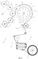
Figure 1 is a schematic top view, with parts removed for clarity, of a labelling machine comprising a cutting device according to the present invention; -
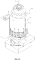
Figure 2a is an enlarged-scale, perspective view, with parts removed for clarity, of the cutting device offigure 1 according to a first embodiment of the present invention; -
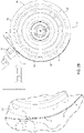
Figure 2b is a schematic top view, with parts removed for clarity, of the cutting device ofFigure 2a ; -
Figure 3a is an enlarged-scale, perspective view, with parts removed for clarity, of the cutting device offigure 1 according to a second embodiment of the present invention; and -
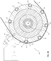
Figure 3b is a schematic, partially sectioned top view, with parts removed for clarity, of the cutting device ofFigure 3a . - With reference to
Figure 1 , number 1 indicates as a whole a labelling machine configured to applylabels 2 ontoarticles 3, such as bottles, receptacles, or the like, destined to contain a pourable product, preferably a pourable food product, such as still or sparkling water, juice, milk, soft drinks, beer, wine, or the like. - According to this non-limiting embodiment shown,
labels 2 applied by labelling machine 1 are defined by strips of labelling material that are cut at predetermined lengths from aweb 4 of labelling material, and to which an adhesive substance, for example a known glue or thermally activatable glue, is pre-applied. - In detail, each
label 2 can be provided with at least two bands (not shown) of glue pre-applied on the inner side of thelabel 2, i.e. the side which faces the outer lateral surface of therespective article 3 thelabel 2 will be applied to. - In greater detail, "pre-applied" means that each
label 2 is provided with such adhesive bands even before cutting thereof, i.e.web 4 is provided with such adhesive bands. - More precisely, each
label 2 is provided with at least one adhesive band at the leading end thereof and with at least one adhesive band at the trailing end thereof. - In one embodiment, each
label 2 is provided with a single adhesive band, conveniently arranged either at the leading end or at the trailing end thereof. - In light of the above,
web 4, which is defined by a series oflabels 2 initially joined to one another, is initially provided with adhesive bands. - Preferably,
web 4 of labelling material is initially wound around one or more storage units, such as reels 5 (only one reel is shown inFigure 1 ), and is progressively unwound, in use, offreel 5. - As visible in
Figure 1 , labelling machine 1 essentially comprises: - a conveyor device, preferably a rotary carousel 6 rotatable around a fixed axis, in particular a vertical axis Z, and configured to advance a plurality of
articles 3 along a conveying path P, in the example shown an arc-shaped, horizontal path; and - an input station I, at which
articles 3 to be labelled are fed to carousel 6; - an output station O, at which labelled
articles 3 exit from carousel 6; and - a labelling module 7 (only partially and schematically shown), arranged peripherally relatively to carousel 6 and configured to feed a plurality of
labels 2 to the carousel 6 itself at an application station A, in order to applylabels 2 torespective articles 3. - In detail,
labelling module 7 comprises: - at least one of the above-mentioned
reels 5 for storingweb 4; - a conveying system 8 configured to advance
web 4 along a feeding path, from a storage station defined byreel 5 towards a cutting station T at whichweb 4 is sequentially cut, and comprising a plurality of unwinding rollers which support, in use,web 4 progressively unwound, in use, fromreel 5 and guide it along the feeding path; - a
cutting device 10 according to the present invention, configured to cut a sequence ofsingle labels 2 fromweb 4, in the form of strips having equal length, thelabels 2 being initially joined together to formweb 4; and - a label transfer device comprising a
rotary vacuum drum 11 rotatable around a fixed axis, preferably a vertical axis X, arranged peripherally to carousel 6 and configured to sequentially receive, on an outerlateral surface 11a thereof, labels 2 cut by the cuttingdevice 10, to retainsuch labels 2 onto outerlateral surface 11a by means of vacuum suction, and to transfersuch labels 2 to carousel 6. - As visible in
Figure 1 ,vacuum drum 11 sequentially receives, in use and at a receiving station R, a free end portion ofweb 4 defining a leading end portion of eachlabel 2, retaining the same onto outerlateral surface 11a. - Preferably,
vacuum drum 11 has a substantially cylindrical configuration. Accordingly, outerlateral surface 11a has a substantially cylindrical shape and labels 2 are conveyed circumferentially from receiving station R to application station A, along a direction of rotation ofvacuum drum 11. - Furthermore,
vacuum drum 11 is rotatably mounted around axis X onto a stationary distributor element (not shown) carried by labellingmodule 7. - In detail, the distributor element comprises first air passages (not shown) connected to a vacuum source (not shown).
Vacuum drum 11 is, in turn, provided withsecond air passages 11b, which are configured to selectively communicate with the first air passages at certain angular positions assumed byvacuum drum 11, as this latter rotates about axis X, and end into a plurality ofvacuum ports 11c formed through outerlateral surface 11a. - In practice, depending on the angular position relative to axis X assumed by
vacuum drum 11,vacuum ports 11c are put in fluid communication, by means of the first air passages andsecond air passages 11b, with the vacuum source. When this happens, a vacuum suction is applied on eachlabel 2, which retains this latter onto outerlateral surface 11a. - In light of the above,
vacuum drum 11 retains, in use,labels 2 onto outerlateral surface 11a by means of vacuum suction. - At stated above, each
label 2 is provided with pre-applied adhesive bands at the leading end and at the trailing end thereof, so thatlabel 2 can be glued to therespective article 3 to be labelled at application station A. - As visible in
Figures 2a and2b , cuttingdevice 10 comprises a rotary element, preferably a blade roller or cuttingroller 12 rotatable about a longitudinal axis, preferably a vertical axis Y, carrying ablade member 13 and conveying, inuse blade member 13 along a circular cutting path around axis Y. - Conveniently,
blade member 13 radially protrudes from an outerlateral surface 14 of cuttingroller 12 and is configured to sequentiallycut web 4 at a cutting station T arranged along the cutting path, in a position adjacent, i.e. peripheral, to the cuttingroller 12, so as to obtain a sequence oflabels 2. - To this end, cutting
device 10 further comprises a fixed element, in particular acounterblade member 15, arranged in a fixed position peripherally to cuttingroller 12 so as to be substantially tangential to the cutting path, and defining an abutment counterblade surface forblade member 13 when this latter cutsweb 4. - In practice, cutting station T is defined between
counterblade member 15 andblade member 13 when this latter is facing the counterblademember 15. - In other words,
web 4 is interposed, in use and at cutting station T, between cuttingroller 12 andcounterblade member 15, the latter acting as an abutment surface forblade member 13 during cutting ofweb 4. - In use, during the labelling process,
web 4 is fed along the feeding path so thatlabels 2 are received and retained byvacuum drum 11 with their inner side facing outwards, in order to allow the correct transfer thereof on therespective articles 3 at application station A. - Thus,
web 4 reaches cutting station T with the inner side, i.e. the side which adhesive is pre-applied onto, facing outerlateral surface 14 of cuttingroller 12. - In other words, cutting
roller 12 receives and handlesweb 4 necessarily cooperating in contact with the inner side of theweb 4 itself. - It is known that, in use, the linear (or peripheral) velocity of cutting
roller 12 is higher than the linear velocity ofweb 4 fed towards cutting station T. - Hence, during the labelling process and especially at the start thereof, a sliding of
web 4 onto outerlateral surface 14 of cuttingroller 12 occurs. Such sliding is even more accentuated as soon as the leading end of onelabel 2 is received byvacuum drum 11 while the trailing end of thesame label 2 is still attached toweb 4, since the linear (or peripheral) velocity ofvacuum drum 11 is even higher than the linear velocity of cuttingroller 12, for known reasons linked to the pitch of thearticles 3 to be labelled. - This can result, over time, in an accumulation of adhesive material, i.e. of glue, onto outer
lateral surface 14 and ontoblade member 13. - When the accumulation of adhesive material reaches a predefined level, it is necessary to stop labelling machine 1 and clean cutting
roller 12 andblade member 13. - According to an aspect of the present invention, cutting
roller 12 comprises a plurality of rollingelements 16 which are arranged at outerlateral surface 14 and radially protrude therefrom; furthermore, rollingelements 16 are mounted to cuttingroller 12 in a rolling manner with respect to outerlateral surface 14. - More specifically, rolling
elements 16 are arranged in a free-rolling or free-turning manner with respect to outerlateral surface 14. - According to the preferred and non-limiting embodiment shown in
Figures 2a and2b , each rollingelement 16 is defined by a sphere, i.e. a rolling sphere, mounted in a rolling manner to cuttingroller 12 and in a respective fixed position onto outerlateral surface 14. - In particular, rolling
elements 16 are arranged at least at a receivingportion 17 of outerlateral surface 14 configured to receive andsupport web 4. In this way, the sliding friction betweenweb 4 and cuttingroller 12 can be minimized, and/or the contact surface between cuttingroller 12 andweb 4 can be minimized, to reduce the wear of theweb 4. Moreover, this can reduce the level of a possible deposition of adhesive or glue on the cuttingroller 12, in case theweb 4 was already provided with glue or adhesive when it is supported by the receivingportion 17. - It is to be noted that the present invention can be used also with a web which is not already provided with adhesive or glue when it is supported by the receiving
portion 17. In this case the labelling machine 1 comprises a gluing station downstream of the cutting device. - Conveniently, each rolling
element 16 radially protrudes from receivingportion 17 of a radial length less than the radial length theblade member 13 protrudes of from outerlateral surface 14, so that rollingelements 16 do not come into contact withcounterblade member 15 during rotation of cuttingroller 12, in use. Therefore, the reduction of the contact surface and/or of the sliding friction betweenweb 4 and the cuttingroller 12 is reduced without generating any other source of wear. - Accordingly, each rolling element or
sphere 16 is rotatable in a rolling manner with respect to receivingportion 17. - More specifically, cutting
roller 12 comprises a plurality ofseats 18, having according to this preferred embodiment a hemispheric shape, obtained on outerlateral surface 14, in particular on receivingportion 17. - Accordingly, each rolling
element 16, i.e. each sphere, is fitted idle at onerespective seat 18 in a rolling manner, so that sliding friction betweenweb 4 and cuttingroller 12 is reduced and rolling friction betweenweb 4 and cuttingroller 12 is increased, in use. - In practice, each rolling
element 16 is cold-fitted within therespective seat 18 in a way that permits a free rolling (or free turning) of the rollingelement 16 within thatseat 18. Therefore, the sliding ofweb 4 onto receivingportion 17 due to the higher linear velocity of cuttingroller 12 is reduced, thanks to the rolling configuration of rollingelements 16. This results in a smaller accumulation of glue onto outerlateral surface 14 and ontoblade member 13, thereby reducing the necessity to stop labelling machine 1 for maintenance. - Preferably, the spheres defining rolling
elements 16 are arranged in a plurality of longitudinal rows 16a along respective longitudinal directions parallel to axis Y. The Applicant has observed that such arrangement is the most effective in terms of sliding friction reduction and of rolling friction increase, for this application. - Preferably, cutting
roller 12 comprises a plurality ofvacuum ports 19 arranged on outerlateral surface 14, in particular at least on receivingportion 17, and fluidly connectable to a vacuum source (known per se and not shown) configured to generate vacuum, in order to apply vacuum, in use, toweb 4 and retain andsupport web 4 on the receivingportion 17 itself. - According to this specific embodiment shown,
vacuum ports 19 are positioned at portions of outerlateral surface 14 arranged between rollingelements 16. - In detail,
vacuum ports 19 are arranged in longitudinal rows which are arranged between the longitudinal rows ofspheres 16, with respect to the circumferential direction relative to axis Y, as shown inFigure 2a . - According to an alternative embodiment not shown,
vacuum ports 19 may be arranged atspheres 16, eachsphere 16 comprising a plurality ofvacuum ports 19 connectable to the vacuum source. - In this last case, each
sphere 16 has a plurality ofvacuum ports 19 arranged in fluid communication with one another and with the vacuum source so that, in use, at least onevacuum port 19 of eachsphere 16 cooperates withweb 4 by applying suction thereon while at least anothervacuum port 19 is in fluid communication with the vacuum source. - More precisely, each
sphere 16 comprises at least one vacuum channel obtained therein, and cuttingroller 12 comprises a vacuum collector channel (not shown) fluidly connectable to the vacuum source and to the vacuum channel of eachsphere 16 and configured to arrange therespective vacuum ports 19 in fluid communication with the vacuum source. - The operation of labelling machine 1 is described hereinafter with reference to a starting condition in which a section of
web 4 has been received onto outerlateral surface 14 of cuttingroller 12 and is approaching cutting station T to be cut by interaction ofblade member 13 andcounterblade member 15. - In this condition,
web 4 cooperates in contact withspheres 16 which are distributed, as explained above, onto receivingportion 17. - Accordingly, the sliding friction of
web 4 onto cuttingroller 12 is reduced (preferably eliminated), whereas rolling friction is increased. - Thus,
web 4 mostly rolls, and almost does not slide (preferably does not slide at all), onto outerlateral surface 14, thereby at least minimizing, preferably annulling) the quantity of glue left thereon and onblade member 13. - With reference to
Figures 3a and3b ,number 10' indicates as a whole a cutting device according to a second embodiment of the present invention, adapted to be implemented in labelling machine 1. - Since cutting
device 10' is functionally and structurally similar to cuttingdevice 10, only the differentiating features between these latter will be described in the following, using the same reference numbers for equivalent or corresponding parts. - In particular, cutting
device 10' differs from cuttingdevice 10 in that cuttingroller 12 of cuttingdevice 10' comprises a plurality of rolling elements 16', each rolling element 16' being defined by a cylinder arranged with its longitudinal axis parallel to axis Y. - It is stated that, apart from their shape and disposition, rolling elements 16' are functionally identical to
rolling elements 16 of cuttingdevice 10. - Accordingly, in this case the
seats 18 have a barrel vault or semi-cylindrical shape. - According to this preferred embodiment,
vacuum ports 19 are arranged at rolling elements, i.e. at cylinders 16', each cylinder 16' comprising a plurality ofvacuum ports 19 connectable to the vacuum source. - In particular, each cylinder 16' has a plurality of
vacuum ports 19 arranged in fluid communication with one another and with the vacuum source so that, in use, at least onevacuum port 19 of each cylinder 16' cooperates withweb 4 by applying suction thereon while at least anothervacuum port 19 is in fluid communication with the vacuum source. - In this way the precision of supporting the
web 4 by the cuttingroller 12 is increased as the suction action applied on theweb 4 can be more precisely distributed by means of suction points obtained on the same elements, which are the cylinders 16', that come into contact with theweb 4. - More precisely, each cylinder 16' comprises at least one
vacuum channel 20 arranged therein. - Accordingly, cutting
roller 12 comprises avacuum collector channel 21 fluidly connectable to the vacuum source and to vacuumchannel 20 of each cylinder 16' and configured to arrange therespective vacuum ports 19 in fluid communication with the vacuum source. - According to an alternative embodiment not shown,
vacuum ports 19 are positioned on portions of the outerlateral surface 14 between the cylinders 16'. - The operation of cutting
device 10' corresponds, mutatis mutandis to the one of cuttingdevice 10. - The advantages of cutting
device - Thanks to the presence of rolling
elements 16, 16', the amount of glue accumulated onto outerlateral surface 14 andblade member 13 is reduced, due to the fact that the sliding friction betweenweb 4 and cuttingroller 12 is reduced and, in particular, "transformed" into rolling friction betweenweb 4 and rollingelements 16, 16'. - This is possible thanks to the free-rolling or free-turning arrangement of rolling
elements 16, 16' on cuttingroller 12, with respect to outerlateral surface 14, in particular to receivingportion 17. - This results in a minimization of the necessary maintenance stops and in an improvement of the overall efficiency of the labelling process.
- Moreover, especially in the case in which
vacuum ports 19 are provided at rollingelements 16, 16', there is almost no contact, preferably no contact at all, between outerlateral surface 14 andweb 4, due to the fact thatweb 4 is only supported by rollingelements 16, 16' . - This results in a further reduction of glue accumulation onto cutting
roller 12 and, thus, in a longer maintenance time interval. - Clearly, changes may be made to cutting
device - In particular, cutting
device
Claims (15)
- Cutting device (10, 10') for a labelling machine (1) configured to apply labels (2) obtained from a web (4) of labelling material onto articles (3) adapted to contain a pourable product, said cutting device (10, 10') comprising a cutting roller (12) rotatable about a longitudinal axis (Y), carrying a blade member (13), which radially protrudes from an outer lateral surface (14) of the cutting roller (12), and conveying, in use, the blade member (13) along a circular cutting path around said axis (Y);
the blade member (13) being configured to sequentially cut said web (4) at a cutting station (T) arranged along said cutting path, in a position adjacent to the cutting roller (12), so as to obtain a sequence of said labels (2);
characterized in that the cutting roller (12) comprises a plurality of rolling elements (16, 16') which are arranged at said outer lateral surface (14) and radially protrude from said outer lateral surface (14), and in that the rolling elements (16, 16') are mounted to the cutting roller (12) in a rolling manner with respect to the outer lateral surface (14). - Cutting device as claimed in claim 1, wherein the rolling elements (16, 16') are arranged at least at a receiving portion (17) of said outer lateral surface (14) configured to receive and support said web (4),
wherein each rolling element (16, 16') radially protrudes from the receiving portion (17) of a radial length less than the radial length the blade member (13) protrudes of from the outer lateral surface (14),
and wherein each rolling element (16, 16') is rotatable in a rolling manner with respect to the receiving portion (17). - Cutting device as claimed in claim 1 or 2, wherein the rolling elements (16, 16') are mounted to the cutting roller (12) in respective fixed positions on the outer lateral surface (14).
- Cutting device as claimed in claim 3, wherein the cutting roller (12) comprises a plurality of seats (18) obtained on the outer lateral surface (14) thereof;
and wherein each rolling element (16, 16') is fitted idle at one respective seat (18) in a rolling manner, so that, in use, sliding friction between the web (4) and the cutting roller (12) is reduced and rolling friction between the web (4) and the cutting roller (12) is increased. - Cutting device (10) as claimed in any one of the foregoing claims, wherein each rolling element is defined by a sphere (16).
- Cutting device as claimed in claim 5 when depending on claim 4, wherein each seat (18) has a hemispheric shape.
- Cutting device as claimed in claim 5 or 6, wherein the spheres (16) are arranged in a plurality of longitudinal rows along respective longitudinal directions parallel to said longitudinal axis (Y).
- Cutting device (10') as claimed in any one of the claims 1 to 4, wherein each rolling element is defined by a cylinder (16') arranged with its longitudinal axis parallel to the longitudinal axis (Y) of the cutting roller (12).
- Cutting device as claimed in claim 8 when depending on claim 4, wherein each seat (18) has a barrel vault or semi-cylindrical shape.
- Cutting device as claimed in any one of the foregoing claims, wherein the cutting roller (12) comprises a plurality of vacuum ports (19) arranged on the outer lateral surface (14) thereof and fluidly connectable to a vacuum source configured to generate vacuum, in order to apply vacuum on the web (4) and retain and support the web (4) on the outer lateral surface (14).
- Cutting device as claimed in claim 10, wherein the vacuum ports (19) are positioned at portions of the outer lateral surface (14) arranged between the rolling elements (16, 16').
- Cutting device as claimed in claim 10, wherein the vacuum ports (19) are arranged at the rolling elements (16, 16'), each rolling element (16, 16') comprising a plurality of vacuum ports (19) connectable to the vacuum source.
- Cutting device as claimed in claim 12, wherein each rolling element (16, 16') has a plurality of vacuum ports (19) arranged in fluid communication with one another and with the vacuum source so that, in use, at least one vacuum port (19) of each rolling element (16, 16') cooperates with the web (4) by applying suction thereon while at least another vacuum port (19) is in fluid communication with the vacuum source.
- Cutting device as claimed in claim 13, wherein each rolling element (16, 16') comprises at least one vacuum channel (20) arranged therein;
and wherein the cutting roller (12) comprises a vacuum collector channel (21) fluidly connectable to the vacuum source and to the vacuum channel (20) of each rolling element (16, 16') and configured to arrange the respective vacuum ports (19) in fluid communication with the vacuum source. - Labelling machine (1) configured to apply labels (2) obtained from a web (4) of labelling material onto articles (3) adapted to contain a pourable product, the labelling machine (1) comprising:- a conveyor device (6) configured to advance the articles (3) to be labelled along a labelling path (P);- a storage unit (5) for initially storing the web;- a plurality of unwinding rollers (8) configured to support the web (4) unwound from the storage unit (5) and to feed the web (4) along a feeding path;- a cutting device (10, 10') as claimed in any one of the foregoing claims; and- a label transfer device (11) configured to receive each label (2) previously cut, to retain such label (2) and to feed such label (2) to the conveyor device (6) for the application onto one respective article (3).
Priority Applications (2)
| Application Number | Priority Date | Filing Date | Title |
|---|---|---|---|
| EP20212731.2A EP4011793B1 (en) | 2020-12-09 | 2020-12-09 | Cutting device for a labelling machine configured to apply labels onto articles adapted to contain a pourable product |
| PCT/EP2021/077680 WO2022122217A1 (en) | 2020-12-09 | 2021-10-07 | Cutting device for a labelling machine configured to apply labels onto articles adapted to contain a pourable product |
Applications Claiming Priority (1)
| Application Number | Priority Date | Filing Date | Title |
|---|---|---|---|
| EP20212731.2A EP4011793B1 (en) | 2020-12-09 | 2020-12-09 | Cutting device for a labelling machine configured to apply labels onto articles adapted to contain a pourable product |
Publications (2)
| Publication Number | Publication Date |
|---|---|
| EP4011793A1 true EP4011793A1 (en) | 2022-06-15 |
| EP4011793B1 EP4011793B1 (en) | 2023-05-24 |
Family
ID=73789914
Family Applications (1)
| Application Number | Title | Priority Date | Filing Date |
|---|---|---|---|
| EP20212731.2A Active EP4011793B1 (en) | 2020-12-09 | 2020-12-09 | Cutting device for a labelling machine configured to apply labels onto articles adapted to contain a pourable product |
Country Status (2)
| Country | Link |
|---|---|
| EP (1) | EP4011793B1 (en) |
| WO (1) | WO2022122217A1 (en) |
Citations (1)
| Publication number | Priority date | Publication date | Assignee | Title |
|---|---|---|---|---|
| US20170369197A1 (en) * | 2016-06-27 | 2017-12-28 | Sidel Participations | Labelling group and method for applying a plurality of labels onto respective articles |
-
2020
- 2020-12-09 EP EP20212731.2A patent/EP4011793B1/en active Active
-
2021
- 2021-10-07 WO PCT/EP2021/077680 patent/WO2022122217A1/en not_active Ceased
Patent Citations (1)
| Publication number | Priority date | Publication date | Assignee | Title |
|---|---|---|---|---|
| US20170369197A1 (en) * | 2016-06-27 | 2017-12-28 | Sidel Participations | Labelling group and method for applying a plurality of labels onto respective articles |
Also Published As
| Publication number | Publication date |
|---|---|
| EP4011793B1 (en) | 2023-05-24 |
| WO2022122217A1 (en) | 2022-06-16 |
Similar Documents
| Publication | Publication Date | Title |
|---|---|---|
| US11186401B2 (en) | Labelling machine configured to apply labels onto articles for containing a pourable product | |
| US5188696A (en) | Wrap around labeling machine | |
| EP0944528B1 (en) | Roll-fed labelling apparatus | |
| EP3619121B1 (en) | A labelling machine for applying label sheets onto articles | |
| US20200165025A1 (en) | Machine and method for labeling containers | |
| EP3446993A1 (en) | Labeling machine with an improved label transfer drum | |
| US11981043B2 (en) | Cutting device for cutting labels from a web of labelling material | |
| US20250214737A1 (en) | Labelling module for applying labels obtained from a web of labelling material onto articles adapted to contain a pourable product | |
| EP4011793B1 (en) | Cutting device for a labelling machine configured to apply labels onto articles adapted to contain a pourable product | |
| CN112930305B (en) | Labeling machine and method for handling labeling material in roll form in an automatic labeling process | |
| EP3992095A1 (en) | Labelling machine and method for applying labels onto articles adapted to contain a pourable product | |
| EP4594194B1 (en) | Labelling module configured for labelling with partial labels | |
| EP1712476B1 (en) | Method and unit for applying labels to products | |
| EP3988462A1 (en) | Labelling machine and method for applying labels onto articles adapted to contain a pourable product | |
| EP4520674A1 (en) | Label transfer drum with single-piece pad devices for labelling containers by means of partial labels | |
| EP4440939B1 (en) | Labelling module for applying labels onto articles adapted to contain a pourable product | |
| WO2025036797A1 (en) | Labelling machine configured for labelling containers by means of partial labels by sliding application | |
| US20260091905A1 (en) | Labeling machine for applying labels to reusable containers | |
| EP3760551A1 (en) | Method for applying labels onto articles adapted to contain a pourable product | |
| EP3115308A1 (en) | A label application apparatus and method | |
| WO2020114766A1 (en) | Labelling machine, method for handling a web-like labelling material in an automated labelling process and label | |
| WO2025061247A1 (en) | Labelling machine with multiple configurations |
Legal Events
| Date | Code | Title | Description |
|---|---|---|---|
| PUAI | Public reference made under article 153(3) epc to a published international application that has entered the european phase |
Free format text: ORIGINAL CODE: 0009012 |
|
| STAA | Information on the status of an ep patent application or granted ep patent |
Free format text: STATUS: THE APPLICATION HAS BEEN PUBLISHED |
|
| AK | Designated contracting states |
Kind code of ref document: A1 Designated state(s): AL AT BE BG CH CY CZ DE DK EE ES FI FR GB GR HR HU IE IS IT LI LT LU LV MC MK MT NL NO PL PT RO RS SE SI SK SM TR |
|
| STAA | Information on the status of an ep patent application or granted ep patent |
Free format text: STATUS: REQUEST FOR EXAMINATION WAS MADE |
|
| 17P | Request for examination filed |
Effective date: 20220830 |
|
| RBV | Designated contracting states (corrected) |
Designated state(s): AL AT BE BG CH CY CZ DE DK EE ES FI FR GB GR HR HU IE IS IT LI LT LU LV MC MK MT NL NO PL PT RO RS SE SI SK SM TR |
|
| GRAP | Despatch of communication of intention to grant a patent |
Free format text: ORIGINAL CODE: EPIDOSNIGR1 |
|
| STAA | Information on the status of an ep patent application or granted ep patent |
Free format text: STATUS: GRANT OF PATENT IS INTENDED |
|
| INTG | Intention to grant announced |
Effective date: 20230228 |
|
| GRAS | Grant fee paid |
Free format text: ORIGINAL CODE: EPIDOSNIGR3 |
|
| GRAA | (expected) grant |
Free format text: ORIGINAL CODE: 0009210 |
|
| STAA | Information on the status of an ep patent application or granted ep patent |
Free format text: STATUS: THE PATENT HAS BEEN GRANTED |
|
| AK | Designated contracting states |
Kind code of ref document: B1 Designated state(s): AL AT BE BG CH CY CZ DE DK EE ES FI FR GB GR HR HU IE IS IT LI LT LU LV MC MK MT NL NO PL PT RO RS SE SI SK SM TR |
|
| REG | Reference to a national code |
Ref country code: GB Ref legal event code: FG4D |
|
| REG | Reference to a national code |
Ref country code: CH Ref legal event code: EP |
|
| REG | Reference to a national code |
Ref country code: DE Ref legal event code: R096 Ref document number: 602020011079 Country of ref document: DE |
|
| P01 | Opt-out of the competence of the unified patent court (upc) registered |
Effective date: 20230428 |
|
| REG | Reference to a national code |
Ref country code: AT Ref legal event code: REF Ref document number: 1569381 Country of ref document: AT Kind code of ref document: T Effective date: 20230615 |
|
| REG | Reference to a national code |
Ref country code: IE Ref legal event code: FG4D |
|
| REG | Reference to a national code |
Ref country code: LT Ref legal event code: MG9D |
|
| REG | Reference to a national code |
Ref country code: NL Ref legal event code: MP Effective date: 20230524 |
|
| REG | Reference to a national code |
Ref country code: AT Ref legal event code: MK05 Ref document number: 1569381 Country of ref document: AT Kind code of ref document: T Effective date: 20230524 |
|
| PG25 | Lapsed in a contracting state [announced via postgrant information from national office to epo] |
Ref country code: SE Free format text: LAPSE BECAUSE OF FAILURE TO SUBMIT A TRANSLATION OF THE DESCRIPTION OR TO PAY THE FEE WITHIN THE PRESCRIBED TIME-LIMIT Effective date: 20230524 Ref country code: PT Free format text: LAPSE BECAUSE OF FAILURE TO SUBMIT A TRANSLATION OF THE DESCRIPTION OR TO PAY THE FEE WITHIN THE PRESCRIBED TIME-LIMIT Effective date: 20230925 Ref country code: NO Free format text: LAPSE BECAUSE OF FAILURE TO SUBMIT A TRANSLATION OF THE DESCRIPTION OR TO PAY THE FEE WITHIN THE PRESCRIBED TIME-LIMIT Effective date: 20230824 Ref country code: NL Free format text: LAPSE BECAUSE OF FAILURE TO SUBMIT A TRANSLATION OF THE DESCRIPTION OR TO PAY THE FEE WITHIN THE PRESCRIBED TIME-LIMIT Effective date: 20230524 Ref country code: ES Free format text: LAPSE BECAUSE OF FAILURE TO SUBMIT A TRANSLATION OF THE DESCRIPTION OR TO PAY THE FEE WITHIN THE PRESCRIBED TIME-LIMIT Effective date: 20230524 Ref country code: AT Free format text: LAPSE BECAUSE OF FAILURE TO SUBMIT A TRANSLATION OF THE DESCRIPTION OR TO PAY THE FEE WITHIN THE PRESCRIBED TIME-LIMIT Effective date: 20230524 |
|
| PG25 | Lapsed in a contracting state [announced via postgrant information from national office to epo] |
Ref country code: RS Free format text: LAPSE BECAUSE OF FAILURE TO SUBMIT A TRANSLATION OF THE DESCRIPTION OR TO PAY THE FEE WITHIN THE PRESCRIBED TIME-LIMIT Effective date: 20230524 Ref country code: PL Free format text: LAPSE BECAUSE OF FAILURE TO SUBMIT A TRANSLATION OF THE DESCRIPTION OR TO PAY THE FEE WITHIN THE PRESCRIBED TIME-LIMIT Effective date: 20230524 Ref country code: LV Free format text: LAPSE BECAUSE OF FAILURE TO SUBMIT A TRANSLATION OF THE DESCRIPTION OR TO PAY THE FEE WITHIN THE PRESCRIBED TIME-LIMIT Effective date: 20230524 Ref country code: LT Free format text: LAPSE BECAUSE OF FAILURE TO SUBMIT A TRANSLATION OF THE DESCRIPTION OR TO PAY THE FEE WITHIN THE PRESCRIBED TIME-LIMIT Effective date: 20230524 Ref country code: IS Free format text: LAPSE BECAUSE OF FAILURE TO SUBMIT A TRANSLATION OF THE DESCRIPTION OR TO PAY THE FEE WITHIN THE PRESCRIBED TIME-LIMIT Effective date: 20230924 Ref country code: HR Free format text: LAPSE BECAUSE OF FAILURE TO SUBMIT A TRANSLATION OF THE DESCRIPTION OR TO PAY THE FEE WITHIN THE PRESCRIBED TIME-LIMIT Effective date: 20230524 Ref country code: GR Free format text: LAPSE BECAUSE OF FAILURE TO SUBMIT A TRANSLATION OF THE DESCRIPTION OR TO PAY THE FEE WITHIN THE PRESCRIBED TIME-LIMIT Effective date: 20230825 |
|
| PG25 | Lapsed in a contracting state [announced via postgrant information from national office to epo] |
Ref country code: FI Free format text: LAPSE BECAUSE OF FAILURE TO SUBMIT A TRANSLATION OF THE DESCRIPTION OR TO PAY THE FEE WITHIN THE PRESCRIBED TIME-LIMIT Effective date: 20230524 |
|
| PG25 | Lapsed in a contracting state [announced via postgrant information from national office to epo] |
Ref country code: SK Free format text: LAPSE BECAUSE OF FAILURE TO SUBMIT A TRANSLATION OF THE DESCRIPTION OR TO PAY THE FEE WITHIN THE PRESCRIBED TIME-LIMIT Effective date: 20230524 |
|
| PG25 | Lapsed in a contracting state [announced via postgrant information from national office to epo] |
Ref country code: SM Free format text: LAPSE BECAUSE OF FAILURE TO SUBMIT A TRANSLATION OF THE DESCRIPTION OR TO PAY THE FEE WITHIN THE PRESCRIBED TIME-LIMIT Effective date: 20230524 Ref country code: SK Free format text: LAPSE BECAUSE OF FAILURE TO SUBMIT A TRANSLATION OF THE DESCRIPTION OR TO PAY THE FEE WITHIN THE PRESCRIBED TIME-LIMIT Effective date: 20230524 Ref country code: RO Free format text: LAPSE BECAUSE OF FAILURE TO SUBMIT A TRANSLATION OF THE DESCRIPTION OR TO PAY THE FEE WITHIN THE PRESCRIBED TIME-LIMIT Effective date: 20230524 Ref country code: EE Free format text: LAPSE BECAUSE OF FAILURE TO SUBMIT A TRANSLATION OF THE DESCRIPTION OR TO PAY THE FEE WITHIN THE PRESCRIBED TIME-LIMIT Effective date: 20230524 Ref country code: DK Free format text: LAPSE BECAUSE OF FAILURE TO SUBMIT A TRANSLATION OF THE DESCRIPTION OR TO PAY THE FEE WITHIN THE PRESCRIBED TIME-LIMIT Effective date: 20230524 Ref country code: CZ Free format text: LAPSE BECAUSE OF FAILURE TO SUBMIT A TRANSLATION OF THE DESCRIPTION OR TO PAY THE FEE WITHIN THE PRESCRIBED TIME-LIMIT Effective date: 20230524 |
|
| REG | Reference to a national code |
Ref country code: DE Ref legal event code: R097 Ref document number: 602020011079 Country of ref document: DE |
|
| PLBE | No opposition filed within time limit |
Free format text: ORIGINAL CODE: 0009261 |
|
| STAA | Information on the status of an ep patent application or granted ep patent |
Free format text: STATUS: NO OPPOSITION FILED WITHIN TIME LIMIT |
|
| 26N | No opposition filed |
Effective date: 20240227 |
|
| PG25 | Lapsed in a contracting state [announced via postgrant information from national office to epo] |
Ref country code: SI Free format text: LAPSE BECAUSE OF FAILURE TO SUBMIT A TRANSLATION OF THE DESCRIPTION OR TO PAY THE FEE WITHIN THE PRESCRIBED TIME-LIMIT Effective date: 20230524 |
|
| PG25 | Lapsed in a contracting state [announced via postgrant information from national office to epo] |
Ref country code: SI Free format text: LAPSE BECAUSE OF FAILURE TO SUBMIT A TRANSLATION OF THE DESCRIPTION OR TO PAY THE FEE WITHIN THE PRESCRIBED TIME-LIMIT Effective date: 20230524 |
|
| REG | Reference to a national code |
Ref country code: CH Ref legal event code: PL |
|
| PG25 | Lapsed in a contracting state [announced via postgrant information from national office to epo] |
Ref country code: LU Free format text: LAPSE BECAUSE OF NON-PAYMENT OF DUE FEES Effective date: 20231209 |
|
| PG25 | Lapsed in a contracting state [announced via postgrant information from national office to epo] |
Ref country code: MC Free format text: LAPSE BECAUSE OF FAILURE TO SUBMIT A TRANSLATION OF THE DESCRIPTION OR TO PAY THE FEE WITHIN THE PRESCRIBED TIME-LIMIT Effective date: 20230524 |
|
| REG | Reference to a national code |
Ref country code: BE Ref legal event code: MM Effective date: 20231231 |
|
| PG25 | Lapsed in a contracting state [announced via postgrant information from national office to epo] |
Ref country code: MC Free format text: LAPSE BECAUSE OF FAILURE TO SUBMIT A TRANSLATION OF THE DESCRIPTION OR TO PAY THE FEE WITHIN THE PRESCRIBED TIME-LIMIT Effective date: 20230524 Ref country code: LU Free format text: LAPSE BECAUSE OF NON-PAYMENT OF DUE FEES Effective date: 20231209 |
|
| REG | Reference to a national code |
Ref country code: IE Ref legal event code: MM4A |
|
| PG25 | Lapsed in a contracting state [announced via postgrant information from national office to epo] |
Ref country code: IE Free format text: LAPSE BECAUSE OF NON-PAYMENT OF DUE FEES Effective date: 20231209 |
|
| PG25 | Lapsed in a contracting state [announced via postgrant information from national office to epo] |
Ref country code: BE Free format text: LAPSE BECAUSE OF NON-PAYMENT OF DUE FEES Effective date: 20231231 |
|
| PG25 | Lapsed in a contracting state [announced via postgrant information from national office to epo] |
Ref country code: FR Free format text: LAPSE BECAUSE OF NON-PAYMENT OF DUE FEES Effective date: 20231231 |
|
| PG25 | Lapsed in a contracting state [announced via postgrant information from national office to epo] |
Ref country code: CH Free format text: LAPSE BECAUSE OF NON-PAYMENT OF DUE FEES Effective date: 20231231 |
|
| PG25 | Lapsed in a contracting state [announced via postgrant information from national office to epo] |
Ref country code: IE Free format text: LAPSE BECAUSE OF NON-PAYMENT OF DUE FEES Effective date: 20231209 Ref country code: FR Free format text: LAPSE BECAUSE OF NON-PAYMENT OF DUE FEES Effective date: 20231231 Ref country code: CH Free format text: LAPSE BECAUSE OF NON-PAYMENT OF DUE FEES Effective date: 20231231 Ref country code: BE Free format text: LAPSE BECAUSE OF NON-PAYMENT OF DUE FEES Effective date: 20231231 |
|
| PG25 | Lapsed in a contracting state [announced via postgrant information from national office to epo] |
Ref country code: BG Free format text: LAPSE BECAUSE OF FAILURE TO SUBMIT A TRANSLATION OF THE DESCRIPTION OR TO PAY THE FEE WITHIN THE PRESCRIBED TIME-LIMIT Effective date: 20230524 |
|
| PG25 | Lapsed in a contracting state [announced via postgrant information from national office to epo] |
Ref country code: BG Free format text: LAPSE BECAUSE OF FAILURE TO SUBMIT A TRANSLATION OF THE DESCRIPTION OR TO PAY THE FEE WITHIN THE PRESCRIBED TIME-LIMIT Effective date: 20230524 |
|
| PG25 | Lapsed in a contracting state [announced via postgrant information from national office to epo] |
Ref country code: CY Free format text: LAPSE BECAUSE OF FAILURE TO SUBMIT A TRANSLATION OF THE DESCRIPTION OR TO PAY THE FEE WITHIN THE PRESCRIBED TIME-LIMIT; INVALID AB INITIO Effective date: 20201209 |
|
| PG25 | Lapsed in a contracting state [announced via postgrant information from national office to epo] |
Ref country code: HU Free format text: LAPSE BECAUSE OF FAILURE TO SUBMIT A TRANSLATION OF THE DESCRIPTION OR TO PAY THE FEE WITHIN THE PRESCRIBED TIME-LIMIT; INVALID AB INITIO Effective date: 20201209 |
|
| GBPC | Gb: european patent ceased through non-payment of renewal fee |
Effective date: 20241209 |
|
| PG25 | Lapsed in a contracting state [announced via postgrant information from national office to epo] |
Ref country code: GB Free format text: LAPSE BECAUSE OF NON-PAYMENT OF DUE FEES Effective date: 20241209 |
|
| PG25 | Lapsed in a contracting state [announced via postgrant information from national office to epo] |
Ref country code: TR Free format text: LAPSE BECAUSE OF FAILURE TO SUBMIT A TRANSLATION OF THE DESCRIPTION OR TO PAY THE FEE WITHIN THE PRESCRIBED TIME-LIMIT Effective date: 20230524 |
|
| PGFP | Annual fee paid to national office [announced via postgrant information from national office to epo] |
Ref country code: DE Payment date: 20251126 Year of fee payment: 6 |
|
| PGFP | Annual fee paid to national office [announced via postgrant information from national office to epo] |
Ref country code: IT Payment date: 20251119 Year of fee payment: 6 |