EP4011558A1 - Procédé et outil d'installation d'un élément de fixation - Google Patents
Procédé et outil d'installation d'un élément de fixation Download PDFInfo
- Publication number
- EP4011558A1 EP4011558A1 EP21206502.3A EP21206502A EP4011558A1 EP 4011558 A1 EP4011558 A1 EP 4011558A1 EP 21206502 A EP21206502 A EP 21206502A EP 4011558 A1 EP4011558 A1 EP 4011558A1
- Authority
- EP
- European Patent Office
- Prior art keywords
- pin
- sleeve
- fastener
- relative
- pintail
- Prior art date
- Legal status (The legal status is an assumption and is not a legal conclusion. Google has not performed a legal analysis and makes no representation as to the accuracy of the status listed.)
- Pending
Links
- 238000000034 method Methods 0.000 title claims abstract description 66
- 241001136800 Anas acuta Species 0.000 claims abstract description 124
- 238000010008 shearing Methods 0.000 claims abstract description 32
- 238000009434 installation Methods 0.000 description 17
- 230000007246 mechanism Effects 0.000 description 17
- 230000003213 activating effect Effects 0.000 description 10
- 239000012190 activator Substances 0.000 description 9
- 238000010586 diagram Methods 0.000 description 7
- 230000015654 memory Effects 0.000 description 7
- 238000004891 communication Methods 0.000 description 6
- 230000006870 function Effects 0.000 description 6
- 238000004519 manufacturing process Methods 0.000 description 5
- 230000004913 activation Effects 0.000 description 4
- 230000008901 benefit Effects 0.000 description 4
- 230000014759 maintenance of location Effects 0.000 description 4
- 230000004048 modification Effects 0.000 description 4
- 238000012986 modification Methods 0.000 description 4
- 230000000295 complement effect Effects 0.000 description 3
- 239000012530 fluid Substances 0.000 description 3
- 238000011900 installation process Methods 0.000 description 3
- 239000000463 material Substances 0.000 description 3
- 238000012545 processing Methods 0.000 description 3
- 241000282472 Canis lupus familiaris Species 0.000 description 2
- 238000005516 engineering process Methods 0.000 description 2
- 238000007689 inspection Methods 0.000 description 2
- 238000012423 maintenance Methods 0.000 description 2
- 230000008520 organization Effects 0.000 description 2
- 230000008569 process Effects 0.000 description 2
- 238000009419 refurbishment Methods 0.000 description 2
- 230000008439 repair process Effects 0.000 description 2
- 230000007704 transition Effects 0.000 description 2
- 101000822695 Clostridium perfringens (strain 13 / Type A) Small, acid-soluble spore protein C1 Proteins 0.000 description 1
- 101000655262 Clostridium perfringens (strain 13 / Type A) Small, acid-soluble spore protein C2 Proteins 0.000 description 1
- 101000655256 Paraclostridium bifermentans Small, acid-soluble spore protein alpha Proteins 0.000 description 1
- 101000655264 Paraclostridium bifermentans Small, acid-soluble spore protein beta Proteins 0.000 description 1
- 238000003491 array Methods 0.000 description 1
- 230000005540 biological transmission Effects 0.000 description 1
- 239000002131 composite material Substances 0.000 description 1
- 238000010276 construction Methods 0.000 description 1
- 238000013461 design Methods 0.000 description 1
- 230000000694 effects Effects 0.000 description 1
- 230000007613 environmental effect Effects 0.000 description 1
- 239000002828 fuel tank Substances 0.000 description 1
- 239000010437 gem Substances 0.000 description 1
- 229910001751 gemstone Inorganic materials 0.000 description 1
- 230000006872 improvement Effects 0.000 description 1
- 230000010354 integration Effects 0.000 description 1
- 230000003287 optical effect Effects 0.000 description 1
- 238000007639 printing Methods 0.000 description 1
- 230000000644 propagated effect Effects 0.000 description 1
- 230000001902 propagating effect Effects 0.000 description 1
- 230000002123 temporal effect Effects 0.000 description 1
- 230000007723 transport mechanism Effects 0.000 description 1
- 239000011800 void material Substances 0.000 description 1
Images


Classifications
-
- B—PERFORMING OPERATIONS; TRANSPORTING
- B25—HAND TOOLS; PORTABLE POWER-DRIVEN TOOLS; MANIPULATORS
- B25B—TOOLS OR BENCH DEVICES NOT OTHERWISE PROVIDED FOR, FOR FASTENING, CONNECTING, DISENGAGING OR HOLDING
- B25B23/00—Details of, or accessories for, spanners, wrenches, screwdrivers
- B25B23/14—Arrangement of torque limiters or torque indicators in wrenches or screwdrivers
- B25B23/1415—Break members; Arrangements specially adapted for break-bolts
-
- F—MECHANICAL ENGINEERING; LIGHTING; HEATING; WEAPONS; BLASTING
- F16—ENGINEERING ELEMENTS AND UNITS; GENERAL MEASURES FOR PRODUCING AND MAINTAINING EFFECTIVE FUNCTIONING OF MACHINES OR INSTALLATIONS; THERMAL INSULATION IN GENERAL
- F16B—DEVICES FOR FASTENING OR SECURING CONSTRUCTIONAL ELEMENTS OR MACHINE PARTS TOGETHER, e.g. NAILS, BOLTS, CIRCLIPS, CLAMPS, CLIPS OR WEDGES; JOINTS OR JOINTING
- F16B19/00—Bolts without screw-thread; Pins, including deformable elements; Rivets
- F16B19/04—Rivets; Spigots or the like fastened by riveting
- F16B19/08—Hollow rivets; Multi-part rivets
- F16B19/10—Hollow rivets; Multi-part rivets fastened by expanding mechanically
- F16B19/1027—Multi-part rivets
- F16B19/1036—Blind rivets
- F16B19/1045—Blind rivets fastened by a pull - mandrel or the like
- F16B19/1072—Blind rivets fastened by a pull - mandrel or the like the pull-mandrel or the like comprising a thread and being rotated with respect to the rivet, thereby mechanically expanding and fastening the rivet
-
- B—PERFORMING OPERATIONS; TRANSPORTING
- B64—AIRCRAFT; AVIATION; COSMONAUTICS
- B64F—GROUND OR AIRCRAFT-CARRIER-DECK INSTALLATIONS SPECIALLY ADAPTED FOR USE IN CONNECTION WITH AIRCRAFT; DESIGNING, MANUFACTURING, ASSEMBLING, CLEANING, MAINTAINING OR REPAIRING AIRCRAFT, NOT OTHERWISE PROVIDED FOR; HANDLING, TRANSPORTING, TESTING OR INSPECTING AIRCRAFT COMPONENTS, NOT OTHERWISE PROVIDED FOR
- B64F5/00—Designing, manufacturing, assembling, cleaning, maintaining or repairing aircraft, not otherwise provided for; Handling, transporting, testing or inspecting aircraft components, not otherwise provided for
- B64F5/10—Manufacturing or assembling aircraft, e.g. jigs therefor
-
- B—PERFORMING OPERATIONS; TRANSPORTING
- B21—MECHANICAL METAL-WORKING WITHOUT ESSENTIALLY REMOVING MATERIAL; PUNCHING METAL
- B21J—FORGING; HAMMERING; PRESSING METAL; RIVETING; FORGE FURNACES
- B21J15/00—Riveting
- B21J15/02—Riveting procedures
- B21J15/04—Riveting hollow rivets mechanically
- B21J15/043—Riveting hollow rivets mechanically by pulling a mandrel
-
- B—PERFORMING OPERATIONS; TRANSPORTING
- B21—MECHANICAL METAL-WORKING WITHOUT ESSENTIALLY REMOVING MATERIAL; PUNCHING METAL
- B21J—FORGING; HAMMERING; PRESSING METAL; RIVETING; FORGE FURNACES
- B21J15/00—Riveting
- B21J15/10—Riveting machines
- B21J15/12—Riveting machines with tools or tool parts having a movement additional to the feed movement, e.g. spin
-
- B—PERFORMING OPERATIONS; TRANSPORTING
- B21—MECHANICAL METAL-WORKING WITHOUT ESSENTIALLY REMOVING MATERIAL; PUNCHING METAL
- B21J—FORGING; HAMMERING; PRESSING METAL; RIVETING; FORGE FURNACES
- B21J15/00—Riveting
- B21J15/10—Riveting machines
- B21J15/14—Riveting machines specially adapted for riveting specific articles, e.g. brake lining machines
- B21J15/142—Aerospace structures
-
- B—PERFORMING OPERATIONS; TRANSPORTING
- B21—MECHANICAL METAL-WORKING WITHOUT ESSENTIALLY REMOVING MATERIAL; PUNCHING METAL
- B21J—FORGING; HAMMERING; PRESSING METAL; RIVETING; FORGE FURNACES
- B21J15/00—Riveting
- B21J15/10—Riveting machines
- B21J15/30—Particular elements, e.g. supports; Suspension equipment specially adapted for portable riveters
- B21J15/32—Devices for inserting or holding rivets in position with or without feeding arrangements
-
- B—PERFORMING OPERATIONS; TRANSPORTING
- B25—HAND TOOLS; PORTABLE POWER-DRIVEN TOOLS; MANIPULATORS
- B25B—TOOLS OR BENCH DEVICES NOT OTHERWISE PROVIDED FOR, FOR FASTENING, CONNECTING, DISENGAGING OR HOLDING
- B25B27/00—Hand tools, specially adapted for fitting together or separating parts or objects whether or not involving some deformation, not otherwise provided for
- B25B27/0007—Tools for fixing internally screw-threaded tubular fasteners
- B25B27/0014—Tools for fixing internally screw-threaded tubular fasteners motor-driven
-
- F—MECHANICAL ENGINEERING; LIGHTING; HEATING; WEAPONS; BLASTING
- F16—ENGINEERING ELEMENTS AND UNITS; GENERAL MEASURES FOR PRODUCING AND MAINTAINING EFFECTIVE FUNCTIONING OF MACHINES OR INSTALLATIONS; THERMAL INSULATION IN GENERAL
- F16B—DEVICES FOR FASTENING OR SECURING CONSTRUCTIONAL ELEMENTS OR MACHINE PARTS TOGETHER, e.g. NAILS, BOLTS, CIRCLIPS, CLAMPS, CLIPS OR WEDGES; JOINTS OR JOINTING
- F16B19/00—Bolts without screw-thread; Pins, including deformable elements; Rivets
- F16B19/04—Rivets; Spigots or the like fastened by riveting
- F16B19/08—Hollow rivets; Multi-part rivets
- F16B19/10—Hollow rivets; Multi-part rivets fastened by expanding mechanically
- F16B19/1027—Multi-part rivets
- F16B19/1036—Blind rivets
- F16B19/1045—Blind rivets fastened by a pull - mandrel or the like
- F16B19/1054—Blind rivets fastened by a pull - mandrel or the like the pull-mandrel or the like being frangible
-
- F—MECHANICAL ENGINEERING; LIGHTING; HEATING; WEAPONS; BLASTING
- F16—ENGINEERING ELEMENTS AND UNITS; GENERAL MEASURES FOR PRODUCING AND MAINTAINING EFFECTIVE FUNCTIONING OF MACHINES OR INSTALLATIONS; THERMAL INSULATION IN GENERAL
- F16B—DEVICES FOR FASTENING OR SECURING CONSTRUCTIONAL ELEMENTS OR MACHINE PARTS TOGETHER, e.g. NAILS, BOLTS, CIRCLIPS, CLAMPS, CLIPS OR WEDGES; JOINTS OR JOINTING
- F16B5/00—Joining sheets or plates, e.g. panels, to one another or to strips or bars parallel to them
- F16B5/04—Joining sheets or plates, e.g. panels, to one another or to strips or bars parallel to them by means of riveting
Definitions
- Some known one-sided (i.e., blind) fasteners are installed by slip-fitting the fastener into a hole of a structure and applying torque to a pin of the fastener. Rotation of the pin deforms a tail of the fastener such that the tail expands to form a retention feature over the back of the structure.
- manual installation of at least some known one-sided fasteners e.g., using one or more manually-operated hand tools, etc.
- the strength required to manually install a one-sided fastener may make it difficult for an individual to complete installation, particularly if the individual is required to consecutively install a group of fasteners.
- manually installing one-sided fasteners may be time-consuming and/or labor intensive.
- a method for installing a fastener into an opening of a structure.
- the fastener includes a sleeve and a pin threadably received into the sleeve.
- the method includes inserting the fastener into the opening, grabbing a pintail of the pin, and deforming a tail of the sleeve radially outward relative to a centerline axis of the fastener by automatically displacing the pin longitudinally along the centerline axis relative to the sleeve.
- the method also includes rotationally shearing the pintail of the pin from a shaft of the pin.
- a method for installing a fastener into an opening of a structure using a tool.
- the fastener includes a sleeve and a pin threadably received into the sleeve.
- the method includes inserting the fastener into the opening, clamping a clamp of the tool to a pintail of the pin, and deforming a tail of the sleeve radially outward relative to a centerline axis of the fastener by activating a linear actuator to displace the clamp longitudinally along the centerline axis relative to the structure such that the pin is displaced longitudinally along the centerline axis relative to the sleeve.
- the method also includes grabbing the pintail of the pin with a wrench of the tool that is interconnected with the clamp, and rotationally shearing the pintail of the pin from a shaft of the pin by activating a rotary actuator to rotate the wrench of the tool.
- a tool for installing a fastener that includes a sleeve and a pin threadably received into the sleeve.
- the tool includes a frame and a clamp mounted to the frame such that the clamp is configured to move longitudinally relative to the frame.
- the clamp is configured to grab a pintail of the pin of the fastener.
- the tool includes a linear actuator operatively connected to the clamp such that the linear actuator is configured to drive linear movement of the clamp relative to the frame.
- the tool includes a wrench mounted to the frame such that the wrench is configured to rotate relative to the frame.
- the wrench is configured to grab the pintail of the pin.
- the tool includes a rotary actuator operatively connected to the wrench such that the rotary actuator is configured to drive rotation of the wrench relative to the frame.
- orientations can be inverted, rotated, or otherwise changed, such that a top side becomes a bottom side if the structure is flipped 180 degrees, becomes a left side or a right side if the structure is pivoted 90°, and the like.
- Certain implementations of the present disclosure provide methods and tools for installing a fastener into an opening of a structure. These implementations provide for inserting the fastener into the opening, grabbing a pintail of the pin, and deforming a tail of the sleeve radially outward relative to a centerline axis of the fastener by automatically displacing the pin longitudinally along the centerline axis relative to the sleeve.
- the pintail of the pin is also rotationally sheared from a shaft of the pin.
- Certain implementations of the present disclosure provide methods and tools that operate in an unconventional manner to install fasteners. Certain implementations of the present disclosure provide methods and tools that enable installation of a one-sided fastener by longitudinally displacing and rotating the pin of the fastener. Certain implementations of the present disclosure enable automated installation of fasteners. Certain implementations of the present disclosure enable fasteners to be installed in a transition or interference fit condition. Certain implementations of the present disclosure decrease the difficulty of installing fasteners. For example, certain implementations of the present disclosure reduce the effort required to install fasteners. Certain implementations of the present disclosure provide methods and tools that more efficiently install fasteners. For example, certain implementations of the present disclosure are less time-consuming and/or labor intensive.
- FIG. 1 a cross-sectional schematic diagram of a tool 100 for installing a fastener (e.g., the fastener 200 shown in Figures 2-4 , etc.) is provided in Figure 1 .
- the tool 100 includes a frame 102, a clamp 104 mounted to the frame 102, a wrench 106 mounted to the frame 102, a linear actuator 108, and a rotary actuator 110.
- the clamp 104 is configured to move longitudinally relative to the frame 102
- the wrench 106 is configured to rotate relative to the frame 102.
- Linear movement of the clamp 104 relative to the frame 102 is driven by the linear actuator 108.
- Rotation of the wrench 106 relative to the frame 102 is driven by the rotary actuator 110.
- the linear actuator 108 and the rotary actuator 110 enable the fastener to be installed using automatic linear movement of the clamp 104 and automatic rotation of the wrench 106, respectively.
- the frame 102 extends a length along a central longitudinal axis 112.
- the frame 102 includes a base 114.
- the base 114 of the frame 102 is configured to engage in physical contact with the fastener (e.g., the fastener 200 shown in Figures 2-4 , etc.) and/or a structure (e.g., the structure 250 shown in Figure 4 , etc.) into which the fastener is being installed.
- the term "frame” includes a support structure of any type having any size, shape, and geometry, such as, but not limited to, a housing, a base, a case, a frame as shown and described herein, and/or the like.
- the frame 102 is not limited to the particular implementation shown herein, but rather may additionally or alternatively include any other structure that enables the tool 100 to function as described and/or illustrated herein.
- the clamp 104 is mounted to the frame 102 such that the clamp 104 is configured to move longitudinally relative to the frame 102. Specifically, the clamp 104 is configured to move longitudinally relative to the frame 102 along the central longitudinal axis 112, as indicated by the arrows 116 and 118 in Figure 1 . The directions 116 and 118 are parallel to the central longitudinal axis 112. As will be described below, linear movement of the clamp 104 relative to the frame 102 during installation of the fastener enables the clamp 104 to move longitudinally along a centerline axis (e.g., the centerline axis 202 shown in Figures 2-4 , etc.) of the fastener relative to the structure within which the fastener is being installed.
- a centerline axis e.g., the centerline axis 202 shown in Figures 2-4 , etc.
- the clamp 104 is mounted on rods 120 of the frame 102.
- the rods 120 define rails along (i.e., on) which the clamp 104 travels as the clamp 104 moves longitudinally along the central longitudinal axis 112 relative to the frame 102. In other words, the clamp 104 moves along both the rods/rails 120 and the central longitudinal axis 112.
- the clamp 104 is mounted to the frame 102 using any other mechanism, structure, and/or the like that enables the clamp 104 to move longitudinally relative to the frame 102 along the central longitudinal axis 112, such as, but not limited to, bearings, gears, tracks, pulleys, guides, cables, chains, other types of rods, other types of rails, and/or the like.
- the clamp 104 is configured to grab a pintail (e.g., the pintail 218 shown in Figures 2-4 , etc.) of a pin (e.g., the pin 206 shown in Figures 2-4 , etc.) of the fastener.
- the clamp 104 is configured to clamp to the pintail of the fastener.
- the clamp 104 When clamped to the pintail of the fastener, longitudinal movement of the clamp 104 relative to the frame 102 enables the clamp 104 to move (i.e., displace) the pin of the fastener longitudinally along the centerline axis (e.g., the centerline axis 202 shown in Figure 2-4 , etc.) of the fastener relative to a sleeve (e.g., the sleeve 204 shown in Figures 2-4 , etc.) of the fastener, as will be described below.
- the centerline axis of the fastener is parallel with the central longitudinal axis 112 when the fastener is held by the tool.
- the clamp 104 may include any clamping mechanism that enables the clamp 104 to grab the pintail of the fastener such that the clamp 104 is enabled to displace (e.g., configured to displace, capable of displacing, etc.) the pin of the fastener longitudinally along the centerline axis of the fastener relative to the sleeve of the fastener.
- the clamping mechanism of the clamp 104 includes two or more jaws 122 that can be moved (e.g., tightened, etc.) radially inward toward the central longitudinal axis 112 to thereby squeeze the pintail of the pin therebetween.
- the clamp 104 additionally or alternatively may include any other clamping mechanism that enables the clamp 104 to function as described and/or illustrated herein, such as, but not limited to, collars, collets, bands, other circular and semi-circular clamping mechanisms, dogs, other types of jaws, and/or the like.
- the clamping mechanism of the clamp 104 may be configured to clamp to (i.e., grab) any structure of the pintail of the pin that enables the clamp 104 to function as described and/or illustrated herein.
- the clamping mechanism of the clamp 104 may be configured to grab one or more of a variety of different structures of the pintail.
- the jaws 122 of the clamp 104 are configured to grab a neck (e.g., the neck 228 shown in Figures 2-4 , etc.) of the pintail.
- Other examples of a pintail structure that the clamping mechanism of the clamp 104 may be configured to grab (i.e., clamp to) include, but are not limited to, collars, flanges, lobes, textured surfaces, and/or the like.
- the clamping mechanism (e.g., the jaws 122, etc.) of the clamp 104 may be actuated to grab the pintail by any power source, mechanism, structure, and/or the like, such as, but not limited to: manually using one or more gears, teeth, handles, knobs, levers, and/or keys (e.g., a chuck key, etc.); automatically using a pneumatic, electric, and/or hydraulic power source; and/or the like.
- the tool 100 includes the linear actuator 108 for longitudinally moving the clamp 104.
- the linear actuator 108 is operatively connected to the clamp 104 such that the linear actuator 108 is configured to drive (e.g., actuate, enable, allow, etc.) linear movement of the clamp 104 along the central longitudinal axis 112 relative to the frame 102.
- linear movement of the clamp 104 along the central longitudinal axis 112 relative to the frame 102 is driven by the linear actuator 108.
- the linear actuator 108 enables the fastener to be installed using automatic linear movement of the clamp 104.
- the linear actuator 108 may include any type of linear actuator and any associated components (e.g., linkage, etc.), such as, but not limited to, hydraulically actuated pistons, other types of hydraulic linear actuators, magnetic linear actuators, screw-type linear actuators, ball screws, lead screws, screw jacks, roller screws, linear motors, telescoping linear actuators, solenoids, servomechanisms, servomotors, hydraulic linear actuators, pneumatic linear actuators, electrical linear actuators, electromechanical linear actuators, electric motors, gears, chains, pulleys, differentials, counterweights, and/or the like.
- the linear actuator 108 may be actuated by any power source, such as, but not limited to, a pneumatic power source, an electric power source, a hydraulic power source, and/or the like.
- the wrench 106 is mounted to the frame 102 such that the wrench 106 is configured to rotate relative to the frame 102. Specifically, the wrench 106 is configured to rotate relative to the frame 102 about the central longitudinal axis 112, as indicated by the arrows 124 and 126 in Figure 1 . As will be described below, rotation of the wrench 106 relative to the frame 102 during installation of the fastener enables the wrench 106 to rotate about the centerline axis of the fastener relative to the structure within which the fastener is being installed (and relative to the sleeve of the fastener). In the implementation shown herein, the wrench 106 is indirectly mounted to the frame 102 via the clamp 104.
- the wrench 106 is mounted to the clamp 104 via one or more bearings 128 that enable the wrench 106 to rotate about the central longitudinal axis 112 relative to the clamp 104 and the frame 102.
- the wrench 106 is mounted directly to the frame 102 (e.g., via one or more bearings, etc.) for rotation about the central longitudinal axis 112 relative to the frame 102.
- the wrench 106 is configured to rotate relative to the clamp 104, in some other implementations the clamp 104 is configured to rotate relative to the frame 102 along with the wrench 106.
- the wrench 106 is mounted to the clamp 104 such that the wrench 106 travels with the clamp 104 longitudinally along the central longitudinal axis 112 relative to the frame 102.
- the wrench 106 is mounted to the frame 102 indirectly via the clamp 104 in the implementation shown in Figure 1 .
- the bearing(s) 128 may include any type of bearing, such as, but not limited to, plain bearings, bushings, journal bearings, sleeve bearings, rifle bearings, composite bearings, rolling-element bearings, bail bearings, roller bearings, jewel bearings, fluid bearings, magnetic bearings, flexure bearings, and/or the like.
- the wrench 106 is mounted to the clamp 104 and/or the frame 102 using any other mechanism, structure, and/or the like that enables the wrench 106 to rotate about the central longitudinal axis 112 relative to the frame 102, such as, but not limited to, gears, tracks, rails, pulleys, guides, cables, chains, and/or the like.
- the wrench 106 is configured to grab the pintail of the pin of the fastener.
- rotation of the wrench 106 relative to the frame 102 enables the wrench 106 to rotate the pin of the fastener about the centerline axis of the fastener relative to the sleeve of the fastener, as will be described below.
- the wrench 106 may include any grabbing mechanism that enables the wrench 106 to grab the pintail of the fastener such that the wrench 106 is enabled to rotate (e.g., configured to rotate, capable of rotating, etc.) the pin of the fastener about the centerline axis of the fastener relative to the sleeve of the fastener.
- the grabbing mechanism of the wrench 106 includes a socket 130 that includes a spline 132 that is configured to mesh with a spline (e.g., the spline 230 shown in Figures 2-4 , etc.) of the pintail of the pin (i.e., the splines 132 and 230 are complementary in shape).
- a spline e.g., the spline 230 shown in Figures 2-4 , etc.
- the pintail of the pin i.e., the splines 132 and 230 are complementary in shape
- the wrench 106 may include any other grabbing mechanism that enables the wrench 106 to function as described and/or illustrated herein, such as, but not limited to, flats, lobes, hexagonal structures, square structures, triangular structures, hexalobular structures, other multi-sided structures, textured surfaces, collars, collets, bands, other circular and semi-circular clamping mechanisms, dogs, jaws, other clamping mechanisms, socket having one or more of the aforementioned structures and/or the like.
- any other grabbing mechanism that enables the wrench 106 to function as described and/or illustrated herein, such as, but not limited to, flats, lobes, hexagonal structures, square structures, triangular structures, hexalobular structures, other multi-sided structures, textured surfaces, collars, collets, bands, other circular and semi-circular clamping mechanisms, dogs, jaws, other clamping mechanisms, socket having one or more of the aforementioned structures and/or the like.
- the grabbing mechanism of the wrench 106 may be configured to grab (e.g., mesh with, interlock with, etc.) any structure of the pintail of the pin that enables the wrench 106 to function as described and/or illustrated herein.
- the wrench 106 may be configured to grab one or more of a variety of different structures of the pintail.
- the spline 132 of the wrench 106 is configured to mesh with the spline (e.g., the spline 230 shown in Figures 2-4 , etc.) of the pintail.
- pintail structure that the wrench 106 may be configured to grab include, but are not limited to, flats, lobes, hexagonal structures, square structures, triangular structures, hexalobular structures, other multi-sided structures, textured surfaces, and/or the like.
- the tool 100 includes the rotary actuator 110 for rotating the wrench 106.
- the rotary actuator 110 is operatively connected to the wrench 106 such that the rotary actuator 110 is configured to drive (e.g., actuate, enable, allow, etc.) rotation of the wrench 106 about the central longitudinal axis 112 relative to the frame 102.
- rotation of the wrench 106 about the central longitudinal axis 112 relative to the frame 102 is driven by the rotary actuator 110.
- the rotary actuator 110 enables the fastener to be installed using automatic rotation of the wrench 106.
- the rotary actuator 110 may include any type of rotary actuator and any associated components (e.g., linkage, etc.), such as, but not limited to, rotary screws, electric motors, stepper motors, servomotors, torque motors, memory wires, fluid power actuators, vacuum actuators, hydraulic rotary actuators, pneumatic rotary actuators, electrical rotary actuators, electromechanical rotary actuators, servomechanisms, gears, chains, pulleys, differentials, and/or the like.
- the rotary actuator 110 may be actuated by any power source, such as, but not limited to, a pneumatic power source, an electric power source, a hydraulic power source, and/or the like.
- the tool 100 includes one or more activators 134 for manually activating the linear actuator 108 and/or one or more activators 136 for manually activating the rotary actuator 110.
- manual selection of the activator 134 by a human operator activates the linear actuator 108 to displace (i.e., move) the clamp 104 longitudinally along the central longitudinal axis 112 of the tool 100 relative to the frame 102.
- manually selecting the activator 134 causes the linear actuator 108 to automatically displace the clamp 104 longitudinally along the central longitudinal axis 112 relative to the frame 102.
- manual selection of the activator 136 by a human operator activates the rotary actuator 110 to rotate the wrench 106 about the central longitudinal axis 112 relative to the frame 102.
- manually selecting the activator 136 causes the rotary actuator 110 to automatically rotate the wrench 106 about the central longitudinal axis 112 relative to the frame 102.
- the activator(s) 134 and 136 each may include any type of activator, such as, but not limited to, buttons, switches, levers, knobs, and/or the like.
- the tool 100 may include and/or be communicatively coupled to one or more optional electronic devices 138 that control activation of the linear actuator 108 and/or the rotary actuator 110.
- the electronic device 138 includes one or more processors 140 and one or more optional memories 142.
- the electronic device 138 is configured to execute some or all of the operations (e.g., activation of a linear actuator, activation of a rotary actuator, etc.) of the methods described herein with respect to Figures 6 and 7 for installing a fastener.
- the electronic device 138 controls positioning of the tool 100 at the intended location of the structure within which the fastener is being installed.
- the tool 100 is manually positioned at the installation location by a human operator.
- the electronic device 138 represents any device executing instructions (e.g., as application programs/software, operating system functionality, or both) to implement the operations and functionality associated with the electronic device 138.
- the electronic device 138 includes a mobile electronic device or any other portable device, for example a mobile telephone, laptop, tablet, computing pad, netbook, and/or the like.
- the electronic device 138 includes less portable devices, for example desktop personal computers, servers, controllers, kiosks, tabletop devices, industrial control devices, and/or the like.
- the electronic device 138 represents a group of processing units, servers, other computing devices, and/or the like in some implementations.
- the electronic device 138 is located onboard the tool 100, while in other implementations the electronic device 138 is located offboard the tool 100 (e.g., at the site of a larger system within which the tool 100 is implemented, at a site remote from a larger system within which the tool 100 is implemented, etc.).
- a sensing apparatus (not shown; e.g., a feedback control loop, etc.) guides the tool 100 to provide alignment of the wrench 106 with the fastener.
- FIGs 2 and 3 illustrate a fastener 200 that can be installed using the tool 100 ( Figures 1 and 4 ).
- the fastener 200 is meant solely as one non-limiting example of a fastener with which the tool 100 may be used to install. Accordingly, the tool 100 is not limited to being used to install the fastener 200, but rather the tool 100 may be used to install fasteners having other sizes, shapes, geometries, and/or the like.
- the fastener 200 extends a length along a centerline axis 202 and includes a sleeve 204 and a pin 206 that is threadably received into the sleeve 204.
- the sleeve 204 extends a length along the centerline axis 202 from a flange 208 of the sleeve 204 to a tail 210 of the sleeve 204.
- the sleeve 204 includes an opening 212 that extends through the length of the sleeve 204.
- the opening 212 of the sleeve 204 is threaded along at least a portion of the length thereof.
- the sleeve 204 includes one or more threads 214 (not visible in Figure 2 ) that extend into an interior surface 216 (not visible in Figure 2 ) of the sleeve 204 that defines the opening 212.
- the tail 210 of the sleeve 204 is configured to be deformed radially outward relative to the centerline axis 202 during installation of the fastener 200.
- the pin 206 extends a length along the centerline axis 202.
- the pin 206 includes a pintail 218 and a shaft 220 that extends outward from the pintail 218 along the centerline axis 202.
- the shaft 220 of the pin 206 is threaded along at least a portion of the length thereof such that the shaft 220 is configured to be threadably received into the sleeve 204.
- the shaft 220 includes one or more threads 222 (not visible in Figure 2 ) that extend into an exterior surface 224 (not visible in Figure 2 ) of shaft 220.
- the threads 222 enable the shaft 220 to be threadably received into the opening 212 of the sleeve 204.
- the pintail 218 of the pin 206 includes a flange 226 (not visible in Figure 2 ).
- the flange 226 has a complementary shape relative to the flange 208 of the sleeve 204 such that the flange 226 of the pintail 218 is configured to seat with (e.g., against, etc.) the flange 208 of the sleeve 204.
- the pintail 218 of the pin 206 includes a neck 228 and a spline 230.
- the clamp 104 ( Figures 1 and 4 ) of the tool 100 is configured to grab the neck 228 of the pintail 218 and the wrench 106 ( Figures 1 and 4 ) of the tool 100 is configured to mesh with the spline 230 of the pintail 218 during installation of the fastener 200.
- the pintail 218 of the pin 206 is frangible such that the pintail 218 of the pin 206 is configured to break from the shaft 220 of the pin 206 during installation of the fastener 200.
- the pintail 218 of the pin 206 is configured to shear from the shaft 220 of the pin 206 when a predetermined amount of torque is applied to the pin 206 while the flange 226 of the pintail 218 is seated with the flange 208 of the sleeve 204.
- the pintail 218 of the pin 206 may be configured to break from the shaft 220 of the pin 206 along a shear line 232 (not visible in Figure 2 ).
- a portion of the pintail 218 remains with the shaft 220 after the pintail 218 has broken from the shaft 220.
- a tapered segment 226a of the flange 226 may remain with the shaft 220 after the pintail 218 has sheared from the shaft 220, as is shown in the example of Figure 4f .
- the opening 252 of the structure 250 includes a countersink 254 along a front side 262 of the structure 250.
- the flange 208 of the sleeve 204 and the countersink 254 are complementary in shape to enable the flange 208 to seat within the countersink 254.
- the opening 252 shown herein has a cylindrical (i.e., circular cross-sectional) shape
- the tool 100 is not limited to installing fasteners into cylindrical openings, but rather may be used to install fasteners into openings that include any other shape in addition or alternative to a cylindrical shape.
- the fastener 200 is inserted into the opening 252 such that the tail 210 of the sleeve 204 of the fastener 200 extends outward along a back side 256 (i.e., opposite the front side 262) of the structure 250 and such that the flange 208 of the sleeve 204 is seated within the countersink 254 of the opening 252, as is shown in Figure 4b .
- the fastener 200 has a clearance fit within the opening 252, wherein the fastener 200 can be inserted into the opening 252 manually (e.g., by a human operator, etc.) or automatically (e.g., using one or more other devices such as, but not limited to, a robotic arm or other robotic device, the electronic device 138, and/or the like) using relatively little force.
- the fastener 200 has an interference (e.g., transition, etc.) fit within the opening 252, wherein the fastener 200 is forced, pushed, hammered, and/or riveted into the opening 252, for example manually (e.g., by a human operator, etc.) or automatically (e.g., using one or more other devices such as, but not limited to, a robotic arm or other robotic device, the electronic device 138, and/or the like).
- an interference e.g., transition, etc.
- the fastener 200 is forced, pushed, hammered, and/or riveted into the opening 252, for example manually (e.g., by a human operator, etc.) or automatically (e.g., using one or more other devices such as, but not limited to, a robotic arm or other robotic device, the electronic device 138, and/or the like).
- the tool 100 is positioned over the fastener 200 such that the clamp 104 extends around the neck 228 of the pintail 218 and such that the spline 132 of the wrench 106 is meshed with the spline 230 of the pintail 218, as shown in Figure 4c .
- the linear actuator 108 ( Figures 1 and 4d ) and the rotary actuator 110 ( Figures 1 and 4e ) are not shown in Figure 4c for clarity.
- the clamp 104 of the tool 100 is then clamped to the pintail 218 of the fastener.
- the jaws 122 of the clamp 104 are moved radially inward toward the axes 112 and 202 to thereby grab the neck 228 of the pintail 218.
- the fastener 200 is first inserted (i.e., loaded) into the tool 100 (e.g., manually by a human operator, automatically via the tool 100 grabbing the fastener 200 from a source of the fasteners 200, etc.) and thereafter inserted into the opening 252 using the tool 100 (i.e., while being held by the tool 100).
- the centerline axis 202 of the fastener 200 extends parallel and co-linear with the central longitudinal axis 112 of the tool 100 when the fastener 200 is held by the tool 100.
- Installation of the fastener 200 further includes deforming the tail 210 of the sleeve 204 radially outward relative to the centerline axis 202 of the fastener 200.
- the tail 210 is deformed by activating the linear actuator 108 to displace the clamp 104 longitudinally along the axes 112 and 202 relative to the structure 250 in the direction 116 such that the pin 206 of the fastener 200 is displaced longitudinally along the centerline axis 202 relative to the sleeve 204 in the direction 116, as shown in Figure 4d .
- deforming the tail 210 radially outward relative to the centerline axis 202 includes automatically displacing the pin 206 longitudinally along the centerline axis 202 relative to the sleeve 204 using the linear actuator 108.
- the deformation of the tail 210 of the sleeve 204 radially outward relative to the centerline axis 202 expands the size of the tail 210 along the back side 256 of the structure 250.
- the expanded tail 210 forms a retention feature that cooperates with the flange 208 of the sleeve 204 to hold the fastener 200 within the opening 252 (and thereby fasten two segments 258 and 260 of the structure 250 together).
- the rotary actuator 110 is not shown in Figure 4d for clarity.
- the base 114 of the frame 102 of the tool 100 includes one or more legs 144 that extend over and engage with the flange 208 of the sleeve 204 and the front side 262 of the structure 250. Accordingly, the base 114 is braced against the front side 262 of the structure 250 and against the flange 208 of the sleeve 204 as the clamp 104 moves the pin 206 longitudinally along the centerline axis 202 relative to the sleeve 204.
- linear actuator 108 and the clamp 104 are shown in the illustrated implementation as pulling on the pin 206 of the fastener to move the pin 206 longitudinally along the centerline axis 202 relative to the sleeve 204, additionally or alternatively the linear actuator 108 and the clamp 104 may move the pin 206 longitudinally along the centerline axis 202 relative to the sleeve 204 by pushing on the pin 206.
- installation of the fastener 200 further includes rotationally shearing the pintail 218 of the pin 206 from the shaft 220 of the pin 206.
- installation of the fastener 200 includes waiting a predetermined amount of time (e.g., one second, five seconds, ten seconds, thirty seconds, etc.) after deforming the tail 210 of the sleeve 204 radially outward before rotationally shearing the pintail 218 from the shaft 220 of the pin 206.
- the linear actuator 108 is not shown in Figure 4e for clarity.
- some implementations of the tool 100 are configured to include a delay between deforming the tail 210 radially outward and rotationally shearing the pintail 218 from the shaft 220.
- the tool 100 is configured such that the amount of the delay (i.e., the predetermined amount of time) is adjustable, which may increase the flexibility of the tool 100, allow for improvement of the tool 100, and/or enable adjustment of the tool 100 for different fastener diameters.
- the pintail 218 is rotationally sheared from the pin shaft 220 by activating the rotary actuator 110 to rotate the wrench 106 of the tool 100 about the axes 112 and 202 (e.g., in the direction 124, etc.) such that the pin 206 of the fastener 200 is rotated about the centerline axis 202 relative to the sleeve 204 of the fastener 200.
- rotationally shearing the pintail 218 from the shaft 220 includes automatically rotating the pin 206 about the centerline axis 202 relative to the sleeve 204 using the rotary actuator 110.
- rotation of the pin 206 relative to the sleeve 204 threads the shaft 220 of the pin 206 further into the sleeve 204 from the position shown in Figure 4d until the flange 226 of the pintail 218 seats within (e.g., against, etc.) the flange 208 of the sleeve 204.
- Further rotation of the pin 206 about the centerline axis 202 relative to the sleeve 204 from the position shown in Figure 4e breaks the pintail 218 of the pin 206 from the shaft 220 of the pin 206 (e.g., along the shear line 232, etc.), as is shown in Figure 4f .
- rotationally shearing the pintail 218 from the shaft 220 includes rotating the pin 206 relative to the sleeve 204 until the pintail 218 breaks from the shaft 220 of the pin 206.
- the pintail 218 is rotationally sheared from the shaft 220 such that a broken end portion 264 of the shaft 220 is approximately flush with the front side 262 of the structure 250 and/or the flange 208 of the sleeve 204, for example as is shown in Figure 4f .
- the broken end portion 264 of the shaft 220 extends above and/or below (as viewed in Figure 4f ) the front side 262 and/or the flange 208.
- FIG 5 illustrates another implementation of a tool 300 for installing a fastener (e.g., the fastener 200 shown in Figures 2-4 , etc.).
- the tool 300 includes a frame 302, a clamp 304 mounted to the frame 302, a wrench 306 mounted to the frame 302, a linear actuator 308, and a rotary actuator 310.
- the clamp 304 is configured to move longitudinally relative to the frame 302, and the wrench 306 is configured to rotate relative to the frame 302.
- Linear movement of the clamp 304 relative to the frame 302 is driven by the linear actuator 308.
- Rotation of the wrench 306 relative to the frame 302 is driven by the rotary actuator 310.
- the linear actuator 308 and the rotary actuator 310 enable the fastener to be installed using automatic linear movement of the clamp 304 and automatic rotation of the wrench 306, respectively.
- the tool 300 is configured to automatically insert a fastener into an opening (e.g., the opening 252 shown in Figure 4 , etc.) with an interference fit.
- the tool 300 is configured to install the fastener into an opening that has an interference fit with the fastener.
- the clamp 304 of the tool 300 includes one or more legs 344 configured to engage the flange (e.g., the flange 208 shown in Figures 2-4 , etc.) of the sleeve (e.g., the sleeve 204 shown in Figures 2-4 , etc.) when the fastener is held by the tool 300.
- the legs 344 of the tool 300 are configured to engage the flange of the sleeve in a substantially similar manner to how the legs 144 of the base 114 of the tool 100 are shown engaging the flange 208 of the sleeve 204 in Figure 4c .
- the legs 344 of the clamp 304 are configured to move longitudinally relative to jaws 322 of the clamp 304 along a central longitudinal axis 312 of the tool 300, as indicated by the arrows 346 and 348 in Figure 5 .
- the legs 344 are configured to be extended outwardly away from the jaws 322 in the direction 346 and retracted inwardly toward the jaws 322 in the direction 348.
- the tool 300 may include a linear actuator 350 that is operatively connected to the legs 344 such that the linear actuator 350 is configured to drive (e.g., actuate, enable, allow, etc.) linear movement of the legs 344 relative to the jaws 322 along the central longitudinal axis 312.
- the linear actuator 350 may include any type of linear actuator and any associated components (e.g., linkage, etc.), such as, but not limited to, hydraulically actuated pistons, other types of hydraulic linear actuators, magnetic linear actuators, screw-type linear actuators, ball screws, lead screws, screw jacks, roller screws, linear motors, telescoping linear actuators, solenoids, servomechanisms, servomotors, hydraulic linear actuators, pneumatic linear actuators, electrical linear actuators, electromechanical linear actuators, electric motors, gears, chains, pulleys, differentials, counterweights, and/or the like.
- the linear actuator 350 may be actuated by any power source, such as, but not limited to, a pneumatic power source, an electric power source, a hydraulic power source, and/or the like.
- the fastener is first inserted (i.e., loaded) into the tool 300 (e.g., manually by a human operator, automatically via the tool 300 grabbing the fastener from a source thereof, etc.).
- the linear actuator 350 may adjust the position of the legs 344 relative to the jaws 322 to enable the tool 300 to hold the fastener such that the legs 344 are engaged with the flange of the sleeve of the fastener while the jaws 322 are engaged with a neck (e.g., the neck 228 shown in Figures 2-4 , etc.) of a pintail (e.g., the pintail 218 shown in Figures 2-4 , etc.) of the fastener.
- a neck e.g., the neck 228 shown in Figures 2-4 , etc.
- a pintail e.g., the pintail 218 shown in Figures 2-4 , etc.
- the tool 300 is then positioned at the installation location (i.e., over the opening) such that a base 314 of the frame 302 is braced against a front side (e.g., the front side 262 of the structure 250 shown in Figure 4 , etc.).
- the linear actuator 308 is then activated to move the clamp 304 longitudinally along the central longitudinal axis 312 relative to the base 114 and the structure (e.g., the structure 250 shown in Figure 4 , etc.) in the direction of the arrow 318.
- the legs 344 of the clamp 304 are locked in position (e.g., using the linear actuator 350, etc.) relative to the jaws 322 of the clamp 304 as the clamp 304 moves longitudinally along the axis 312 in the direction 318 toward the structure such that the legs 344 move toward the structure along with the jaws 322. Accordingly, as the clamp 304 moves longitudinally along the axis 312 in the direction 318 toward the structure, the engagement between the legs 344 and the flange of the fastener sleeve forcibly inserts the fastener into the opening until the flange of the sleeve is seated within a seat (e.g., the countersink 254 shown in Figure 4 , etc.) of the opening.
- the clamp 304 of the tool 300 thus enables the fastener to be automatically inserted into an opening with an interference fit.
- the remainder of the installation process can be performed to complete installation of the fastener.
- relative movement between the legs 344 and the jaws 322 of the clamp 304 can be used to accommodate movement to the different relative positions between the pin and the sleeve of the fastener.
- the linear actuator 350 may control extension of the legs 344 away from the jaws 322 (i.e., in the direction 346) as the clamp 304 moves in the direction of the arrow 316 to form the retention feature (e.g., the expanded tail 210 shown in Figures 4e-4f , etc.) of the fastener.
- the linear actuator 350 may control retraction of the legs 344 toward the jaws 322 (i.e., in the direction 348) as the pin of the fastener is rotated to seat a flange (e.g., the flange 226 shown in Figures 2-4 , etc.) of the pintail of the pin within the flange of the sleeve.
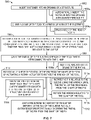
- FIG 6 is a flow chart illustrating a method 400 for installing a fastener (e.g., the fastener 200 shown in Figures 2-4 , etc.) into an opening (e.g., the opening 252 shown in Figure 4 , etc.) of a structure (e.g., the structure 250 shown in Figure 4 , etc.) according to an implementation.
- the fastener includes a sleeve (e.g., the sleeve 204 shown in Figures 2-4 , etc.) and a pin (e.g., the pin 206 shown in Figures 2-4 , etc.) threadably received into the sleeve.
- the method 400 includes inserting, at 402, the fastener into the opening of the structure.
- the method 400 includes grabbing a pintail of the pin. In some implementations, grabbing at 404 the pintail of the pin includes meshing, at 404a, with a spline of the pintail of the pin.
- the method 400 includes deforming, at 406, a tail of the sleeve radially outward relative to a centerline axis of the fastener by automatically displacing the pin longitudinally along the centerline axis relative to the sleeve.
- deforming at 406 the tail of the sleeve radially outward by automatically displacing the pin relative to the sleeve along the centerline axis includes automatically displacing, at 406a, the pin along the centerline axis relative to the sleeve using a linear actuator (e.g., the linear actuator 108 shown in Figures 1 and 4 , the linear actuator 308 shown in Figure 5 , etc.).
- a linear actuator e.g., the linear actuator 108 shown in Figures 1 and 4 , the linear actuator 308 shown in Figure 5 , etc.
- deforming at 406 the tail of the sleeve radially outward by automatically displacing the pin relative to the sleeve along the centerline axis include pulling, at 406b, on the pin.
- deforming at 406 the tail of the sleeve radially outward by automatically displacing the pin relative to the sleeve along the centerline axis includes bracing, at 406c, against a side of the structure and a flange of the sleeve.
- the method 400 includes rotationally shearing the pintail of the pin from a shaft of the pin.
- rotationally shearing at 408 the pintail of the pin from the shaft of the pin includes rotating, at 408a, the pin relative to the sleeve until the pintail of the pin breaks from the shaft of the pin.
- rotationally shearing at 408 the pintail of the pin from the shaft of the pin includes automatically rotating, at 408b, the pin relative to the sleeve using a rotary actuator (e.g., the rotary actuator 110 shown in Figures 1 and 4 , the rotary actuator 310 shown in Figure 5 , etc.).
- a rotary actuator e.g., the rotary actuator 110 shown in Figures 1 and 4 , the rotary actuator 310 shown in Figure 5 , etc.
- rotationally shearing at 408 the pintail of the pin from the shaft of the pin includes shearing, at 408c, the pintail from the shaft such that the shaft is approximately flush with at least one of a side of the structure or a flange of the sleeve.
- Some implementations of the method 400 further include waiting, at 410, a predetermined amount of time after deforming the tail of the sleeve radially outward before rotationally shearing the pintail of the pin from the shaft of the pin.
- Figure 7 is a flow chart illustrating a method 500 for installing a fastener (e.g., the fastener 200 shown in Figures 2-4 , etc.) into an opening (e.g., the opening 252 shown in Figure 4 , etc.) of a structure (e.g., the structure 250 shown in Figure 4 , etc.) using a tool (e.g., the tool 100 shown in Figures 1 and 4 , the tool 300 shown in Figure 5 , etc.) according to an implementation.
- a fastener e.g., the fastener 200 shown in Figures 2-4 , etc.
- an opening e.g., the opening 252 shown in Figure 4 , etc.
- a structure e.g., the structure 250 shown in Figure 4 , etc.
- a tool e.g., the tool 100 shown in Figures 1 and 4 , the tool 300 shown in Figure 5 , etc.
- the fastener includes a sleeve (e.g., the sleeve 204 shown in Figures 2-4 , etc.) and a pin (e.g., the pin 206 shown in Figures 2-4 , etc.) threadably received into the sleeve.
- the method 500 includes inserting, at 502, the fastener into the opening of the structure. In some implementations, inserting at 502 the fastener into the opening of the structure includes automatically inserting, at 502a, the fastener into the opening with an interference fit.
- the method 500 includes clamping a clamp of the tool to a pintail of the pin. In some implementations, clamping at 504 the clamp of the tool to the pintail of the pin includes grabbing, at 504a, a neck of the pintail of the pin.
- the method 500 includes deforming a tail of the sleeve radially outward relative to a centerline axis of the fastener by activating a linear actuator (e.g., the linear actuator 108 shown in Figures 1 and 4 , the linear actuator 308 shown in Figure 5 , etc.) to displace the clamp longitudinally along the centerline axis relative to the structure such that the pin is displaced longitudinally along the centerline axis relative to the sleeve.
- a linear actuator e.g., the linear actuator 108 shown in Figures 1 and 4 , the linear actuator 308 shown in Figure 5 , etc.
- the method 500 includes grabbing the pintail of the pin with a wrench of the tool that is interconnected with the clamp.
- grabbing at 508 the pintail of the pin with the wrench of the tool includes meshing, at 508a, the wrench with a spline of the pintail of the pin.
- the method 500 includes rotationally shearing, at 510, the pintail of the pin from a shaft of the pin by activating a rotary actuator (e.g., the rotary actuator 110 shown in Figures 1 and 4 , the rotary actuator 310 shown in Figure 5 , etc.) to rotate the wrench of the tool.
- a rotary actuator e.g., the rotary actuator 110 shown in Figures 1 and 4 , the rotary actuator 310 shown in Figure 5 , etc.
- rotationally shearing at 510 the pintail of the pin from the shaft of the pin includes rotating, at 510a, the pin relative to the sleeve using the wrench until the pintail of the pin breaks from the shaft of the pin.
- rotationally shearing at 510 the pintail of the pin from the shaft of the pin includes rotating, at 510b, the wrench relative to the clamp of the tool.
- Rotationally shearing at 510 the pintail of the pin from the shaft of the pin optionally includes shearing, at 510c, the pintail from the shaft such that the shaft is approximately flush with at least one of a side of the structure or a flange of the sleeve.
- Some implementations of the method 500 further include waiting, at 512, a predetermined amount of time after deforming the tail of the sleeve radially outward before rotationally shearing the pintail of the pin from the shaft of the pin.
- examples of the disclosure may be described in the context of using the methods and tools disclosed herein to build and/or service (e.g., maintenance, inspection, modification, reconfiguration, refurbishment, repair, replacement, etc.) one or more portions of an aircraft 600 that includes an airframe 602 with a plurality of high-level systems 604 and an interior 606.
- high-level systems 604 include one or more of a propulsion system 608, an electrical system 610, a hydraulic fluid system 612, a control system 614, and an environmental system 616. Any number of other systems can be included.
- the methods and tools disclosed herein can be used with any other type of aircraft, such as, but not limited to, transport aircraft, military aircraft, rotorcraft (e.g., helicopters, etc.), lighter than air vehicles (e.g., balloons, etc.), and/or the like.
- transport aircraft military aircraft
- rotorcraft e.g., helicopters, etc.
- lighter than air vehicles e.g., balloons, etc.
- aerospace example the principles can be applied to other industries, such as, but not limited to, the automotive industry, the marine industry, and/or the like.
- illustrative method 700 can include specification and design 702 of an aircraft (e.g., the aircraft 600 shown in Figure 8 , etc.) and material procurement 704. During production, component and subassembly manufacturing 406 and system integration 708 of the aircraft take place. Thereafter, the aircraft can go through certification and delivery 710 to be placed in service 712. While in service by a customer, the aircraft is scheduled for routine maintenance and service 714 (which can also include inspection, modification, reconfiguration, refurbishment, repair, replacement, and so on).
- routine maintenance and service 714 which can also include inspection, modification, reconfiguration, refurbishment, repair, replacement, and so on).
- the operating environment of the methods and tools disclosed herein may include a fuel tank, a wing, a fuselage, and/or the like of an aircraft and one or more of the methods and/or tools disclosed herein may be used therein to service one or more components of the aircraft therein.
- a system integrator can include, without limitation, any number of aircraft manufacturers and major-system subcontractors
- a third party can include, without limitation, any number of vendors, subcontractors, and suppliers
- an operator can be an airline, leasing company, military entity, service organization, and so on.
- the present disclosure is operable with an electronic device (i.e., a computing apparatus) according to an implementation as a functional block diagram 800 in Figure 10 .
- components of a computing apparatus 802 are implemented as a part of an electronic device according to one or more implementations described in this specification.
- the computing apparatus 802 comprises one or more processors 804, for example microprocessors, controllers, and/or any other suitable type of processors for processing computer executable instructions to control the operation of the electronic device.
- platform software comprising an operating system 806 and/or any other suitable platform software is provided on the apparatus 802 to enable application software 808 to be executed on the device.
- Computer executable instructions are provided using any computer-readable media that are accessible by the computing apparatus 802.
- Computer-readable media include, for example and without limitation, computer storage media such as a memory 810 and communications media.
- Computer storage media, such as a memory 810 include volatile and non-volatile, removable, and non-removable media implemented in any method or technology for storage of information such as computer readable instructions, data structures, program modules or the like.
- Computer storage media include, but are not limited to, RAM, ROM, EPROM, EEPROM, flash memory or other memory technology, CD-ROM, digital versatile disks (DVD) or other optical storage, magnetic cassettes, magnetic tape, magnetic disk storage or other magnetic storage devices, or any other non-transmission medium that can be used to store information for access by a computing apparatus.
- communication media embody computer readable instructions, data structures, program modules, and/or the like in a modulated data signal, such as a carrier wave and/or other transport mechanism.
- computer storage media do not include communication media. Therefore, a computer storage medium should not be interpreted to be a propagating signal per se. Propagated signals per se are not examples of computer storage media.
- the computer storage medium (the memory 810) is shown within the computing apparatus 802, it will be appreciated by a person skilled in the art, that in some implementations the storage is distributed or located remotely and accessed via a network or other communication link (e.g. using a communication interface 812).
- the computing apparatus 802 comprises an input/output controller 814 configured to output information to one or more output devices 816, for example a display and/or a speaker, which is separate from or integral to the electronic device.
- the input/output controller 814 is also configured, in some implementations, to receive and process an input from one or more input devices 818, for example, a keyboard, a microphone, and/or a touchpad.
- the output device 816 also acts as the input device.
- An example of such a device is a touch sensitive display.
- the input/output controller 814 also outputs data to devices other than the output device, e.g. a locally connected printing device.
- a user provides input to the input device(s) 818 and/or receives output from the output device(s) 816.
- the functionality described herein is performed, at least in part, by one or more hardware logic components.
- the computing apparatus 802 is configured by the program code when executed by the processor 804 to execute the implementations of the operations and functionality described.
- the functionality described herein is performed, at least in part, by one or more hardware logic components.
- illustrative types of hardware logic components include Field-programmable Gate Arrays (FPGAs), Application-specific Integrated Circuits (ASICs), Program-specific Standard Products (ASSPs), System-on-a-chip systems (SOCs), Complex Programmable Logic Devices (CPLDs), Graphics Processing Units (GPUs), and/or the like.
- examples of the disclosure are capable of implementation with numerous other general purpose or special purpose computing system environments, configurations, and/or devices.
- Examples of well-known computing systems, environments, and/or configurations that can be suitable for use with aspects of the disclosure include, but are not limited to, mobile computing devices, personal computers, server computers, hand-held or laptop devices, multiprocessor systems, microprocessor-based systems, set top boxes, programmable consumer electronics, mobile telephones, mobile computing and/or communication devices, network PCs, minicomputers, mainframe computers, controllers, distributed computing environments that include any of the above systems and/or devices, and/or the like.
- Such systems and/or devices can accept input from the user in any way, including from input devices such as a keyboard or pointing device, via gesture input, proximity input (for example by hovering), and/or via voice input.
- Implementations of the disclosure may be described in the general context of computer-executable instructions, such as program modules, executed by one or more computers or other devices in software, firmware, hardware, or a combination thereof.
- the computer-executable instructions can be organized into one or more computer-executable components or modules.
- program modules include, but are not limited to, routines, programs, objects, components, and data structures that perform particular tasks or implement particular abstract data types.
- aspects and implementations of the disclosure can be implemented with any number and organization of such components or modules. For example, aspects and implementations of the disclosure are not limited to the specific computer-executable instructions or the specific components or modules illustrated in the figures and described herein. Other examples of the disclosure can include different computer-executable instructions and/or components having more or less functionality than illustrated and described herein.
- aspects and implementations of the disclosure transform the general-purpose computer into a special-purpose computing device when configured to execute the instructions described herein.
- a structure, limitation, or element that is "configured to” perform a task or operation is particularly structurally formed, constructed, or adapted in a manner corresponding to the task or operation.
- an object that is merely capable of being modified to perform the task or operation is not “configured to” perform the task or operation as used herein.
- A, B, and C means "at least one of A and/or at least one of B and/or at least one of C.”
- the phrase “and/or”, as used in the specification and in the claims, should be understood to mean “either or both” of the elements so conjoined, i.e., elements that are conjunctively present in some cases and disjunctively present in other cases. Multiple elements listed with “and/or” should be construed in the same fashion, i.e., "one or more" of the elements so conjoined. Other elements may optionally be present other than the elements specifically identified by the "and/or” clause, whether related or unrelated to those elements specifically identified.
- a reference to "A and/or B", when used in conjunction with open-ended language such as “comprising” can refer, in one implementation, to A only (optionally including elements other than B); in another implementation, to B only (optionally including elements other than A); in yet another implementation, to both A and B (optionally including other elements); etc.
- the phrase "at least one,” in reference to a list of one or more elements, should be understood to mean at least one element selected from any one or more of the elements in the list of elements, but not necessarily including at least one of each and every element specifically listed within the list of elements and not excluding any combinations of elements in the list of elements.
- This definition also allows that elements may optionally be present other than the elements specifically identified within the list of elements to which the phrase "at least one" refers, whether related or unrelated to those elements specifically identified.
- “at least one of A and B" can refer, in one implementation, to at least one, optionally including more than one, A, with no B present (and optionally including elements other than B); in another implementation, to at least one, optionally including more than one, B, with no A present (and optionally including elements other than A); in yet another implementation, to at least one, optionally including more than one, A, and at least one, optionally including more than one, B (and optionally including other elements); etc.
Applications Claiming Priority (1)
| Application Number | Priority Date | Filing Date | Title |
|---|---|---|---|
| US202063122921P | 2020-12-08 | 2020-12-08 |
Publications (1)
| Publication Number | Publication Date |
|---|---|
| EP4011558A1 true EP4011558A1 (fr) | 2022-06-15 |
Family
ID=78528742
Family Applications (1)
| Application Number | Title | Priority Date | Filing Date |
|---|---|---|---|
| EP21206502.3A Pending EP4011558A1 (fr) | 2020-12-08 | 2021-11-04 | Procédé et outil d'installation d'un élément de fixation |
Country Status (3)
| Country | Link |
|---|---|
| US (1) | US20220178398A1 (fr) |
| EP (1) | EP4011558A1 (fr) |
| CN (1) | CN114620245A (fr) |
Families Citing this family (1)
| Publication number | Priority date | Publication date | Assignee | Title |
|---|---|---|---|---|
| US20230069811A9 (en) * | 2020-12-17 | 2023-03-02 | Sps Technologies, Llc | Two-piece blind fastener and installation tool |
Citations (5)
| Publication number | Priority date | Publication date | Assignee | Title |
|---|---|---|---|---|
| EP1382406A2 (fr) * | 2002-07-18 | 2004-01-21 | Newfrey LLC | Procédé et dispositif de surveillance de la pose de rivets aveugles |
| US20040231467A1 (en) * | 2003-05-20 | 2004-11-25 | Gerhart Hufnagl | Blind fastener and nose assembly for installation of the blind fastener |
| US20190160520A1 (en) * | 2017-11-28 | 2019-05-30 | Sps Technologies, Llc | Automatic double-action fastener installation tool |
| US20200230691A1 (en) * | 2019-01-23 | 2020-07-23 | The Boeing Company | Blind fastener tool with pulling fingers |
| WO2021041508A1 (fr) * | 2019-08-26 | 2021-03-04 | Sps Technologies, Llc | Boulon serti à deux pièces et outil d'installation |
Family Cites Families (8)
| Publication number | Priority date | Publication date | Assignee | Title |
|---|---|---|---|---|
| US3181338A (en) * | 1962-07-26 | 1965-05-04 | Standard Pressed Steel Co | Power hand tool |
| DE3535761C1 (de) * | 1985-10-07 | 1987-03-26 | Messerschmitt Boelkow Blohm | Nietautomat |
| US9015920B2 (en) * | 1997-07-21 | 2015-04-28 | Newfrey Llc | Riveting system and process for forming a riveted joint |
| US6892431B2 (en) * | 2000-11-06 | 2005-05-17 | Meikle Ny, Inc. | Hand held spin-pull tool for installing threaded inserts and method for using same |
| US6732563B1 (en) * | 2003-03-17 | 2004-05-11 | Dick Chen | Rivet tool head |
| FR2914208B1 (fr) * | 2007-03-30 | 2009-05-08 | Eads Europ Aeronautic Defence | Dispositif d'insertion et de sertissage de bague pour fixation a bague sertie sur une tige. |
| US9593706B2 (en) * | 2012-11-11 | 2017-03-14 | The Boeing Company | Structural blind fastener and method of installation |
| FR3016417B1 (fr) * | 2014-01-14 | 2016-01-22 | Lisi Aerospace | Rivet pour fixation aveugle, outil de pose associe et methode de pose d'un tel rivet |
-
2021
- 2021-11-04 EP EP21206502.3A patent/EP4011558A1/fr active Pending
- 2021-12-06 CN CN202111478002.8A patent/CN114620245A/zh active Pending
- 2021-12-06 US US17/543,660 patent/US20220178398A1/en active Pending
Patent Citations (5)
| Publication number | Priority date | Publication date | Assignee | Title |
|---|---|---|---|---|
| EP1382406A2 (fr) * | 2002-07-18 | 2004-01-21 | Newfrey LLC | Procédé et dispositif de surveillance de la pose de rivets aveugles |
| US20040231467A1 (en) * | 2003-05-20 | 2004-11-25 | Gerhart Hufnagl | Blind fastener and nose assembly for installation of the blind fastener |
| US20190160520A1 (en) * | 2017-11-28 | 2019-05-30 | Sps Technologies, Llc | Automatic double-action fastener installation tool |
| US20200230691A1 (en) * | 2019-01-23 | 2020-07-23 | The Boeing Company | Blind fastener tool with pulling fingers |
| WO2021041508A1 (fr) * | 2019-08-26 | 2021-03-04 | Sps Technologies, Llc | Boulon serti à deux pièces et outil d'installation |
Also Published As
| Publication number | Publication date |
|---|---|
| US20220178398A1 (en) | 2022-06-09 |
| CN114620245A (zh) | 2022-06-14 |
Similar Documents
| Publication | Publication Date | Title |
|---|---|---|
| US10166641B2 (en) | Method and system for conforming assembly systems to contours of curved surfaces | |
| EP2637930B1 (fr) | Système de chargement d'un moteur | |
| EP3254958B1 (fr) | Système d'aile pliable | |
| EP4011558A1 (fr) | Procédé et outil d'installation d'un élément de fixation | |
| US8770515B1 (en) | Movement assistance system for a storage bin | |
| US9021704B2 (en) | Electromagnetic clamping method | |
| EP2612717B1 (fr) | Outil et procédé de rivetage avec normalisation électromagnétique du tas de contre-frappe | |
| EP2628565A1 (fr) | Dispositif de rivetage pour fuselage d'avion | |
| CN105840693B (zh) | 半系统扭矩制动装置 | |
| CN101506033A (zh) | 制造壳体结构的方法、装置和成套设备 | |
| CN111635984B (zh) | 一种孔的手持式拉扭耦合冷挤压强化装置及强化方法 | |
| GB2548245B (en) | One-sided fastener assembly and methods and systems for installing the same | |
| US20150266174A1 (en) | Apparatus and Method for Remote Fastener Installation | |
| CN213497592U (zh) | 一种临时紧固件安装装置 | |
| US9365278B2 (en) | Variation compensating assembly | |
| EP4227544A1 (fr) | Manchons aveugles structurels et systèmes et procédés associés pour serrer une première structure par rapport à une seconde structure pour produire une structure serrée | |
| JP2023118066A (ja) | ブラインドファスナーならびにブラインドファスナーを取り付けるための関連するシステム及び方法 | |
| EP4350341A1 (fr) | Procédé de contrôle d'arbres de transmission et d'autres corps | |
| CN110921555A (zh) | 一种汽车维修用升降装置 |
Legal Events
| Date | Code | Title | Description |
|---|---|---|---|
| PUAI | Public reference made under article 153(3) epc to a published international application that has entered the european phase |
Free format text: ORIGINAL CODE: 0009012 |
|
| STAA | Information on the status of an ep patent application or granted ep patent |
Free format text: STATUS: THE APPLICATION HAS BEEN PUBLISHED |
|
| AK | Designated contracting states |
Kind code of ref document: A1 Designated state(s): AL AT BE BG CH CY CZ DE DK EE ES FI FR GB GR HR HU IE IS IT LI LT LU LV MC MK MT NL NO PL PT RO RS SE SI SK SM TR |
|
| STAA | Information on the status of an ep patent application or granted ep patent |
Free format text: STATUS: REQUEST FOR EXAMINATION WAS MADE |
|
| 17P | Request for examination filed |
Effective date: 20221116 |
|
| RBV | Designated contracting states (corrected) |
Designated state(s): AL AT BE BG CH CY CZ DE DK EE ES FI FR GB GR HR HU IE IS IT LI LT LU LV MC MK MT NL NO PL PT RO RS SE SI SK SM TR |
|
| RAP3 | Party data changed (applicant data changed or rights of an application transferred) |
Owner name: THE BOEING COMPANY |
|
| TPAC | Observations filed by third parties |
Free format text: ORIGINAL CODE: EPIDOSNTIPA |
|
| RIC1 | Information provided on ipc code assigned before grant |
Ipc: B21J 15/14 20060101ALI20231115BHEP Ipc: B21J 15/12 20060101ALI20231115BHEP Ipc: F16B 19/10 20060101ALI20231115BHEP Ipc: F16B 5/04 20060101ALI20231115BHEP Ipc: B21J 15/04 20060101ALI20231115BHEP Ipc: B25B 27/00 20060101ALI20231115BHEP Ipc: B25B 23/14 20060101AFI20231115BHEP |
|
| GRAP | Despatch of communication of intention to grant a patent |
Free format text: ORIGINAL CODE: EPIDOSNIGR1 |
|
| STAA | Information on the status of an ep patent application or granted ep patent |
Free format text: STATUS: GRANT OF PATENT IS INTENDED |
|
| INTG | Intention to grant announced |
Effective date: 20240116 |
|
| GRAJ | Information related to disapproval of communication of intention to grant by the applicant or resumption of examination proceedings by the epo deleted |
Free format text: ORIGINAL CODE: EPIDOSDIGR1 |
|
| STAA | Information on the status of an ep patent application or granted ep patent |
Free format text: STATUS: REQUEST FOR EXAMINATION WAS MADE |