EP4011487B1 - Method and means for the preparation of solutions from dry chemicals - Google Patents
Method and means for the preparation of solutions from dry chemicals Download PDFInfo
- Publication number
- EP4011487B1 EP4011487B1 EP21201199.3A EP21201199A EP4011487B1 EP 4011487 B1 EP4011487 B1 EP 4011487B1 EP 21201199 A EP21201199 A EP 21201199A EP 4011487 B1 EP4011487 B1 EP 4011487B1
- Authority
- EP
- European Patent Office
- Prior art keywords
- inner chamber
- lower housing
- grid
- fluid
- nozzle
- Prior art date
- Legal status (The legal status is an assumption and is not a legal conclusion. Google has not performed a legal analysis and makes no representation as to the accuracy of the status listed.)
- Active
Links
Images



Classifications
-
- B—PERFORMING OPERATIONS; TRANSPORTING
- B05—SPRAYING OR ATOMISING IN GENERAL; APPLYING FLUENT MATERIALS TO SURFACES, IN GENERAL
- B05B—SPRAYING APPARATUS; ATOMISING APPARATUS; NOZZLES
- B05B7/00—Spraying apparatus for discharge of liquids or other fluent materials from two or more sources, e.g. of liquid and air, of powder and gas
- B05B7/02—Spray pistols; Apparatus for discharge
- B05B7/04—Spray pistols; Apparatus for discharge with arrangements for mixing liquids or other fluent materials before discharge
- B05B7/0416—Spray pistols; Apparatus for discharge with arrangements for mixing liquids or other fluent materials before discharge with arrangements for mixing one gas and one liquid
- B05B7/0425—Spray pistols; Apparatus for discharge with arrangements for mixing liquids or other fluent materials before discharge with arrangements for mixing one gas and one liquid without any source of compressed gas, e.g. the air being sucked by the pressurised liquid
-
- B—PERFORMING OPERATIONS; TRANSPORTING
- B01—PHYSICAL OR CHEMICAL PROCESSES OR APPARATUS IN GENERAL
- B01F—MIXING, e.g. DISSOLVING, EMULSIFYING OR DISPERSING
- B01F21/00—Dissolving
- B01F21/20—Dissolving using flow mixing
- B01F21/22—Dissolving using flow mixing using additional holders in conduits, containers or pools for keeping the solid material in place, e.g. supports or receptacles
-
- B—PERFORMING OPERATIONS; TRANSPORTING
- B01—PHYSICAL OR CHEMICAL PROCESSES OR APPARATUS IN GENERAL
- B01F—MIXING, e.g. DISSOLVING, EMULSIFYING OR DISPERSING
- B01F25/00—Flow mixers; Mixers for falling materials, e.g. solid particles
- B01F25/20—Jet mixers, i.e. mixers using high-speed fluid streams
- B01F25/25—Mixing by jets impinging against collision plates
-
- B—PERFORMING OPERATIONS; TRANSPORTING
- B01—PHYSICAL OR CHEMICAL PROCESSES OR APPARATUS IN GENERAL
- B01F—MIXING, e.g. DISSOLVING, EMULSIFYING OR DISPERSING
- B01F25/00—Flow mixers; Mixers for falling materials, e.g. solid particles
- B01F25/30—Injector mixers
- B01F25/31—Injector mixers in conduits or tubes through which the main component flows
- B01F25/312—Injector mixers in conduits or tubes through which the main component flows with Venturi elements; Details thereof
- B01F25/3124—Injector mixers in conduits or tubes through which the main component flows with Venturi elements; Details thereof characterised by the place of introduction of the main flow
- B01F25/31243—Eductor or eductor-type venturi, i.e. the main flow being injected through the venturi with high speed in the form of a jet
-
- Y—GENERAL TAGGING OF NEW TECHNOLOGICAL DEVELOPMENTS; GENERAL TAGGING OF CROSS-SECTIONAL TECHNOLOGIES SPANNING OVER SEVERAL SECTIONS OF THE IPC; TECHNICAL SUBJECTS COVERED BY FORMER USPC CROSS-REFERENCE ART COLLECTIONS [XRACs] AND DIGESTS
- Y10—TECHNICAL SUBJECTS COVERED BY FORMER USPC
- Y10T—TECHNICAL SUBJECTS COVERED BY FORMER US CLASSIFICATION
- Y10T137/00—Fluid handling
- Y10T137/0318—Processes
-
- Y—GENERAL TAGGING OF NEW TECHNOLOGICAL DEVELOPMENTS; GENERAL TAGGING OF CROSS-SECTIONAL TECHNOLOGIES SPANNING OVER SEVERAL SECTIONS OF THE IPC; TECHNICAL SUBJECTS COVERED BY FORMER USPC CROSS-REFERENCE ART COLLECTIONS [XRACs] AND DIGESTS
- Y10—TECHNICAL SUBJECTS COVERED BY FORMER USPC
- Y10T—TECHNICAL SUBJECTS COVERED BY FORMER US CLASSIFICATION
- Y10T137/00—Fluid handling
- Y10T137/4891—With holder for solid, flaky or pulverized material to be dissolved or entrained
Definitions
- This disclosure relates to water treatment, and more particularly to apparatus for introducing solutions of dry chemicals into a water stream.
- Untreated water provides a hospitable environment for the growth of bacteria, algae, and other undesirable and potentially unhealthful organisms. It has become common practice to treat water on a periodic or continuous basis by introducing treatment chemicals to control such organisms.
- Chemical feeders have been developed for bringing water into contact with solid, dry treatment chemicals so that the chemical material is dissolved in the water in a controlled manner.
- the feeder dissolves solid pellets of calcium hypochlorite (cal hypo) to introduce chlorine into the water stream; the quantity of chlorine in the water is generally expressed as a concentration of free available chlorine (FAC).
- cal hypo calcium hypochlorite
- An effective feeder design must provide dissolution at a desired rate, so as to maintain the desired FAC concentration, while avoiding undesirable deposits or residues; this is especially important in the case of cal hypo which produces calcium carbonate deposits.
- WO 03/047715 relates to feeders for introducing treatment chemicals into a recirculating water stream from a swimming pool or the like.
- WO 03/047715 discloses in particular an apparatus for dissolving and delivering a solution of a solid chemical material including a housing having a base member and upwardly extending side walls, said base member and side walls defining a cavity, and a chamber having side walls within said cavity, the bottom of the side walls of said chamber being adjacent to said base member and the side walls of said chamber being spaced from the side walls of the housing, an improvement comprising: a nozzle disposed in said chamber for discharging fluid in which said solid chemical material is soluble upwardly into an inner chamber, so as to cause a fluid surface in the inner chamber to be locally elevated in a portion of said surface and a method for preparing a chemical solution, comprising: providing a chemical feeder including an upper housing having a grid at the bottom thereof, and a lower housing having a nozzle installed therein, the nozzle oriented so as to discharge fluid vertically upward toward the grid, discharging fluid from the nozzle to cause a fluid surface in the chemical feeder to be locally elevated in an area of said surface above the
- an apparatus according to claim 1 and method according to claim 4 are provided for preparation of a chemical solution.
- an apparatus includes a lower housing and an upper housing.
- the lower housing has a base, an upper plate, and a side wall; the upper plate has a central opening therein.
- the upper housing has a side wall, a lower extremity of which is connected to the upper plate.
- a grid is mounted on the upper plate and covers the central opening; the grid forms at least a portion of a lower boundary of an upper chamber within the upper housing.
- a wall within the lower housing divides the interior of the lower housing into a central inner chamber and an annular outer chamber; this wall has a height substantially equal to an interior height of the side wall of the lower housing. One portion of the wall has a reduced height to permit fluid flow from the inner chamber to the outer chamber.
- a nozzle is disposed in the inner chamber for discharging fluid into the inner chamber toward the grid, so as to cause a fluid surface in the inner chamber to be locally elevated in a portion of said surface.
- the nozzle comprises an eductor having fluid intake ports to create a venturi effect and thereby draw fluid in the inner chamber into the eductor.
- the eductor causes the fluid surface in the inner chamber to be locally elevated in an area above the nozzle, so that the surface in that area rises above the grid; the fluid rising above the grid dissolves chemical material located in the upper chamber and disposed on the grid.
- the chemical material may be in the form of tablets, briquettes, chips, pellets, granules, etc. Dissolved material then drops down through the grid into the inner chamber and mixes with fluid in the inner chamber. The chemical solution then flows from the inner chamber to the outer chamber and out through an outlet port.
- a method for preparing a chemical solution includes the steps of providing a chemical feeder with an upper housing having a grid at the bottom thereof and lower housing having a nozzle oriented so as to discharge water vertically upward toward the grid; discharging fluid from the nozzle to cause a fluid surface in the chemical feeder to be locally elevated in an area above the nozzle, so that the surface in that area rises above the grid; dissolving chemical material disposed on top of the grid, in accordance with the fluid rising above the grid; and conducting a mixture of water and the dissolved material out of the lower housing.
- FIG. 1 illustrates an apparatus for dissolving dry chemicals (a chemical feeder 1) according to an embodiment of the disclosure.
- Feeder 1 has a lower housing 2 and an upper housing 3.
- Components of feeder 1, including housings 2, 3, are shown as circular cylinders; it will be appreciated that alternate embodiments of the disclosure may have shapes other than circular cylinders.
- Lower housing 2 has an outer side wall 11, an upper plate 12 and a base 17; the outer side wall extends upward from the base to the upper plate.
- base 17 and side wall 11 define a cavity.
- the upper plate 12 has a central opening which is covered by a grid 10.
- Upper housing 3 has a side wall 13, the bottom extremity of which connects to upper plate 12 while surrounding grid 10.
- the inner surface 23 of side wall 13, at the bottom extremity of side wall 13, is proximate to or adjacent to the outer edge 9 of grid 10.
- Upper housing 3 has a removable lid 14; in this embodiment, lid 14 is secured to the top edge of side wall 13 by an O-ring seal.
- the interior space bounded by side wall 13 forms an upper chamber 8 with grid 10 at the bottom thereof.
- a wall 4 within lower housing 2 surrounds the central portion of the interior of lower housing 2, and accordingly divides the interior of lower housing 2 into an inner chamber 6 and an annular outer chamber 7. (Inner chamber 6 is thus located within the cavity defined by base 17 and side wall 11.)
- the bottom of wall 4 is connected to base 17.
- Wall 4 has a height substantially equal to the interior height of outer side wall 11, except for a portion in which the top of the wall has a cutout 5.
- a nozzle is mounted in the inner chamber for discharging fluid toward the grid.
- the nozzle comprises an eductor 15, mounted vertically so that an outlet port thereof is directed upward toward the grid.
- Eductor 15 has an inlet port connecting to a water feed line (not shown) through a coupler 16.
- coupler 16 is disposed in an opening in base 17, connecting to the feed line underneath the base.
- Eductor 15 is configured to mix water from the feed line with chemical solution already formed in the feeder, drawing the solution through ports that create a venturi effect.
- the chemical solution is conducted out of the outer chamber of the feeder through an outlet port 18 located in the outer side wall 11.
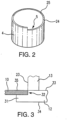
- Interior wall 4 is shown in isolation in FIG. 2 .
- a portion of the wall (typically about 10° of arc), has its height reduced by cutout 5, permitting fluid flow from the inner chamber to the outer chamber over the wall at the cutout portion.
- the arc of cutout 5 may vary from 1 ° of arc to 360° of arc, in which case the entire wall has its height reduced to permit fluid flow over the wall in any direction.
- the reduction in height is typically a small fraction of the height of the wall; when the wall is installed inside housing 2, the top edges 24, 25 of both the cutout portion and the remainder of the wall are in the upper part of the interior of housing 2.
- Cutout 5 is oriented to be 180° opposite port 18 (see FIGS. 1 and 5 ), so that flow from the inner chamber into the outer chamber is in the direction opposite to flow out of the feeder through outlet port 18.
- FIG. 3 is a detail view of the outer edge portion of grid 10; grid 10 covers the opening in upper plate 12 and is surrounded by wall 13.
- upper plate 12 has a notch 32 formed therein, so that the thickness of upper plate 12 is reduced in an inner edge portion 31.
- Grid 10 is mounted on top of and supported by edge portion 31. The depth of notch 32 may be chosen so that the top surface 33 of upper plate 12 and the top surface 35 of grid 10 are coplanar.
- the inner diameter of wall 13 may be matched to the diameter of grid 10 so that inner surface 23 of wall 13 is adjacent to the outer edge of the grid.
- grid 10 generally has a uniform thickness less than that of upper plate 12; grid 10 does not extend below the plane of the underside 34 of upper plate 12.
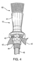
- FIG. 4 illustrates details of eductor 15; eductor 15 is for example a "Tank Mixing Eductor” from Spraying Systems Co., Wheaton, Illinois.
- the eductor has an inlet port 44 that connects to water feed line 45, and a discharge port 41. (Coupler 16 is omitted from FIG. 4 to more clearly show the eductor inlet.)
- the eductor also has fluid intake ports 42 that create a venturi effect and thereby draw chemical solution back into the eductor, as shown schematically by arrows 43.
- pieces of dry chemical material 80 in the form of tablets, briquettes, chips, pellets, granules, or the like
- Discharge 60 from the eductor causes the fluid surface 61 in the inner chamber 6 to be locally elevated in an area 62 of the surface above the eductor.
- the inner chamber is a circular cylinder with eductor 15 mounted in a radially central portion thereof; accordingly, the locally elevated portion 62 of the fluid surface will be at a central circular portion of the grid.
- FIG. 6 illustrates another embodiment of the disclosure, in which feeder 51 has an upper chamber 58 with a diameter larger than that of upper chamber 8 in feeder 1.
- Feeder 51 therefore can hold a larger quantity of dry chemicals; this is an advantage in applications where the feeder is to operate unattended for extended periods.
- the lower extremity of side wall 57 is spaced apart from the outer edge of grid 10.
- chamber 58 has a cone-shaped insert 52 mounted therein.
- Cone 52 is shown in isolation in FIG. 7 .
- cone 52 has a small lower open end and a large open upper end.
- the outer edge 53 of the upper end contacts the interior surface of the side wall of the upper housing, and the lower end has an inner edge 54 with a circumference approximately matching that of the grid, so that inner edge 54 is proximate to the outer edge of the grid.
- the water feed line connection is through the side wall 11 rather than through the base 17.
- Eductor 15 is connected through coupler 16 and a 90° elbow 73 to a substantially horizontal water feed line 71.
- Water feed line 71 extends through an opening in wall 4 and connects to inlet port 72.
- FIG. 9 shows concentrations of FAC in solution produced by a feeder embodying the disclosure at various flow rates.
- Flow rates were in the range 2-6 gallons per minute (GPM), corresponding to water pressure in the range 7.5-54 psi.
- the eductor inlet port had a diameter of approximately 3/8 inch, and the eductor outlet was located 3-3/4 inch below the grid.
- FAC concentrations were obtained in the range 1250-3010 ppm, varying nearly linearly with the flow rate. It will be appreciated that these FAC concentrations are substantially higher than obtained from typical chemical feeders.
Landscapes
- Chemical & Material Sciences (AREA)
- Chemical Kinetics & Catalysis (AREA)
- Accessories For Mixers (AREA)
Description
- This disclosure relates to water treatment, and more particularly to apparatus for introducing solutions of dry chemicals into a water stream.
- Water treatment is needed in a variety of applications. Untreated water provides a hospitable environment for the growth of bacteria, algae, and other undesirable and potentially unhealthful organisms. It has become common practice to treat water on a periodic or continuous basis by introducing treatment chemicals to control such organisms.
- Chemical feeders have been developed for bringing water into contact with solid, dry treatment chemicals so that the chemical material is dissolved in the water in a controlled manner. In a typical application of a chemical feeder, the feeder dissolves solid pellets of calcium hypochlorite (cal hypo) to introduce chlorine into the water stream; the quantity of chlorine in the water is generally expressed as a concentration of free available chlorine (FAC).
- An effective feeder design must provide dissolution at a desired rate, so as to maintain the desired FAC concentration, while avoiding undesirable deposits or residues; this is especially important in the case of cal hypo which produces calcium carbonate deposits. In particular, it is desirable to implement a chemical feeder that can continuously deliver a high concentration of FAC for an extended period of unattended operation.
WO 03/047715 -
WO 03/047715 - In accordance with the disclosure, an apparatus according to
claim 1 and method according toclaim 4 are provided for preparation of a chemical solution. - According to one aspect of the disclosure, an apparatus includes a lower housing and an upper housing. The lower housing has a base, an upper plate, and a side wall; the upper plate has a central opening therein. The upper housing has a side wall, a lower extremity of which is connected to the upper plate. A grid is mounted on the upper plate and covers the central opening; the grid forms at least a portion of a lower boundary of an upper chamber within the upper housing. A wall within the lower housing divides the interior of the lower housing into a central inner chamber and an annular outer chamber; this wall has a height substantially equal to an interior height of the side wall of the lower housing. One portion of the wall has a reduced height to permit fluid flow from the inner chamber to the outer chamber. A nozzle is disposed in the inner chamber for discharging fluid into the inner chamber toward the grid, so as to cause a fluid surface in the inner chamber to be locally elevated in a portion of said surface. The nozzle comprises an eductor having fluid intake ports to create a venturi effect and thereby draw fluid in the inner chamber into the eductor.
- In operation, the eductor causes the fluid surface in the inner chamber to be locally elevated in an area above the nozzle, so that the surface in that area rises above the grid; the fluid rising above the grid dissolves chemical material located in the upper chamber and disposed on the grid. The chemical material may be in the form of tablets, briquettes, chips, pellets, granules, etc. Dissolved material then drops down through the grid into the inner chamber and mixes with fluid in the inner chamber. The chemical solution then flows from the inner chamber to the outer chamber and out through an outlet port.
- According to another aspect of the disclosure, a method for preparing a chemical solution includes the steps of providing a chemical feeder with an upper housing having a grid at the bottom thereof and lower housing having a nozzle oriented so as to discharge water vertically upward toward the grid; discharging fluid from the nozzle to cause a fluid surface in the chemical feeder to be locally elevated in an area above the nozzle, so that the surface in that area rises above the grid; dissolving chemical material disposed on top of the grid, in accordance with the fluid rising above the grid; and conducting a mixture of water and the dissolved material out of the lower housing.
- The foregoing has outlined, rather broadly, the preferred features of the present disclosure so that those skilled in the art may better understand the detailed description of the disclosure that follows. Additional features of the disclosure will be described hereinafter that form the subject of the claims of the disclosure. Those skilled in the art should appreciate that they can readily use the disclosed conception and specific embodiment as a basis for designing or modifying other structures for carrying out the same purposes of the present disclosure and that such other structures do not depart from the spirit and scope of the disclosure in its broadest form.
-
-
FIG. 1 is a schematic cross-section view of an apparatus for dissolving dry chemicals, according to an embodiment of the disclosure. -
FIG. 2 is a perspective view of the inner chamber wall of the apparatus ofFIG. 1 . -
FIG. 3 is a detail view of the grid support in the apparatus ofFIG. 1 . -
FIG. 4 illustrates details of an eductor used in the apparatus ofFIG. 1 . -
FIG. 5 schematically illustrates preparation of a solution from dry chemicals, using the apparatus ofFIG. 1 . -
FIG. 6 is a schematic cross-section view of an apparatus for dissolving a larger quantity of dry chemicals, according to another embodiment of the disclosure. -
FIG. 7 is a perspective view of the upper chamber cone of the apparatus ofFIG. 6 . -
FIG. 8 illustrates an alternative arrangement of the eductor and eductor inlet, according to an additional embodiment of the disclosure. -
FIG. 9 is a graph showing free available chlorine (FAC) concentrations obtained with a chemical feeder embodying the disclosure at various water flow rates. -
FIG. 1 illustrates an apparatus for dissolving dry chemicals (a chemical feeder 1) according to an embodiment of the disclosure. Feeder 1 has alower housing 2 and anupper housing 3. (Components offeeder 1, includinghousings Lower housing 2 has anouter side wall 11, anupper plate 12 and abase 17; the outer side wall extends upward from the base to the upper plate. In an embodiment,base 17 andside wall 11 define a cavity. - The
upper plate 12 has a central opening which is covered by agrid 10.Upper housing 3 has aside wall 13, the bottom extremity of which connects toupper plate 12 while surroundinggrid 10. Theinner surface 23 ofside wall 13, at the bottom extremity ofside wall 13, is proximate to or adjacent to theouter edge 9 ofgrid 10.Upper housing 3 has aremovable lid 14; in this embodiment,lid 14 is secured to the top edge ofside wall 13 by an O-ring seal. As shown inFIG. 1 , the interior space bounded byside wall 13 forms anupper chamber 8 withgrid 10 at the bottom thereof. - A
wall 4 withinlower housing 2 surrounds the central portion of the interior oflower housing 2, and accordingly divides the interior oflower housing 2 into aninner chamber 6 and an annularouter chamber 7. (Inner chamber 6 is thus located within the cavity defined bybase 17 andside wall 11.) The bottom ofwall 4 is connected tobase 17.Wall 4 has a height substantially equal to the interior height ofouter side wall 11, except for a portion in which the top of the wall has acutout 5. - A nozzle is mounted in the inner chamber for discharging fluid toward the grid. The nozzle comprises an
eductor 15, mounted vertically so that an outlet port thereof is directed upward toward the grid.Eductor 15 has an inlet port connecting to a water feed line (not shown) through acoupler 16. In this embodiment,coupler 16 is disposed in an opening inbase 17, connecting to the feed line underneath the base.Eductor 15 is configured to mix water from the feed line with chemical solution already formed in the feeder, drawing the solution through ports that create a venturi effect. The chemical solution is conducted out of the outer chamber of the feeder through anoutlet port 18 located in theouter side wall 11. -
Interior wall 4 is shown in isolation inFIG. 2 . In this embodiment, a portion of the wall (typically about 10° of arc), has its height reduced bycutout 5, permitting fluid flow from the inner chamber to the outer chamber over the wall at the cutout portion. The arc ofcutout 5 may vary from 1 ° of arc to 360° of arc, in which case the entire wall has its height reduced to permit fluid flow over the wall in any direction. As shown inFIG. 2 , the reduction in height is typically a small fraction of the height of the wall; when the wall is installed insidehousing 2, thetop edges housing 2. During operation of the feeder, chemical solution in theinner chamber 6 overflows into theouter chamber 7 over the reduced-height portion of the wall, and then exits the outer chamber throughoutlet port 18.Cutout 5 is oriented to be 180° opposite port 18 (seeFIGS. 1 and5 ), so that flow from the inner chamber into the outer chamber is in the direction opposite to flow out of the feeder throughoutlet port 18. -
FIG. 3 is a detail view of the outer edge portion ofgrid 10;grid 10 covers the opening inupper plate 12 and is surrounded bywall 13. In this embodiment,upper plate 12 has anotch 32 formed therein, so that the thickness ofupper plate 12 is reduced in aninner edge portion 31.Grid 10 is mounted on top of and supported byedge portion 31. The depth ofnotch 32 may be chosen so that thetop surface 33 ofupper plate 12 and thetop surface 35 ofgrid 10 are coplanar. In addition, as shown inFIG. 3 , the inner diameter ofwall 13 may be matched to the diameter ofgrid 10 so thatinner surface 23 ofwall 13 is adjacent to the outer edge of the grid. As shown inFIG. 3 ,grid 10 generally has a uniform thickness less than that ofupper plate 12;grid 10 does not extend below the plane of theunderside 34 ofupper plate 12. -
FIG. 4 illustrates details ofeductor 15;eductor 15 is for example a "Tank Mixing Eductor" from Spraying Systems Co., Wheaton, Illinois. The eductor has aninlet port 44 that connects towater feed line 45, and adischarge port 41. (Coupler 16 is omitted fromFIG. 4 to more clearly show the eductor inlet.) The eductor also hasfluid intake ports 42 that create a venturi effect and thereby draw chemical solution back into the eductor, as shown schematically byarrows 43. - During operation of the feeder (see
FIG. 5 ), pieces of dry chemical material 80 (in the form of tablets, briquettes, chips, pellets, granules, or the like) inupper chamber 8 rest on top ofgrid 10. Water enters the feeder througheductor 15.Discharge 60 from the eductor causes thefluid surface 61 in theinner chamber 6 to be locally elevated in anarea 62 of the surface above the eductor. In this embodiment, the inner chamber is a circular cylinder witheductor 15 mounted in a radially central portion thereof; accordingly, the locallyelevated portion 62 of the fluid surface will be at a central circular portion of the grid. - The surface of the fluid in this
area 62 rises above the grid, so as to contactpieces 81 of the dry chemical resting on the central portion of the grid. Thedry chemical pieces 81 thus dissolve, the dissolved chemical dropping down through the grid into theinner chamber 6 and resulting in formation of a chemical solution ininner chamber 6. As noted above, the chemical solution is drawn back into the eductor (arrows 43) through theeductor intake ports 42, and is again discharged throughoutlet port 41. The chemical solution overflows intoouter chamber 7, spilling overwall 4 in the area ofcutout 5; the solution then exits the feeder throughoutlet port 18. -
FIG. 6 illustrates another embodiment of the disclosure, in whichfeeder 51 has anupper chamber 58 with a diameter larger than that ofupper chamber 8 infeeder 1.Feeder 51 therefore can hold a larger quantity of dry chemicals; this is an advantage in applications where the feeder is to operate unattended for extended periods. The lower extremity ofside wall 57 is spaced apart from the outer edge ofgrid 10. To direct pieces of dry chemical inward towardgrid 10 and prevent pieces of dry chemical from landing onplate 12 instead ofgrid 10,chamber 58 has a cone-shapedinsert 52 mounted therein. -
Cone 52 is shown in isolation inFIG. 7 . As shown inFIG. 7 ,cone 52 has a small lower open end and a large open upper end. Theouter edge 53 of the upper end contacts the interior surface of the side wall of the upper housing, and the lower end has an inner edge 54 with a circumference approximately matching that of the grid, so that inner edge 54 is proximate to the outer edge of the grid. - In another embodiment, illustrated in
FIG. 8 , the water feed line connection is through theside wall 11 rather than through thebase 17.Eductor 15 is connected throughcoupler 16 and a 90°elbow 73 to a substantially horizontalwater feed line 71.Water feed line 71 extends through an opening inwall 4 and connects toinlet port 72. -
FIG. 9 shows concentrations of FAC in solution produced by a feeder embodying the disclosure at various flow rates. Flow rates were in the range 2-6 gallons per minute (GPM), corresponding to water pressure in the range 7.5-54 psi. The eductor inlet port had a diameter of approximately 3/8 inch, and the eductor outlet was located 3-3/4 inch below the grid. FAC concentrations were obtained in the range 1250-3010 ppm, varying nearly linearly with the flow rate. It will be appreciated that these FAC concentrations are substantially higher than obtained from typical chemical feeders. - While the disclosure has been described in terms of specific embodiments, it is evident in view of the foregoing description that numerous alternatives, modifications and variations will be apparent to those skilled in the art. Accordingly, the disclosure is intended to encompass all such alternatives, modifications and variations which fall within the scope of the following claims
Claims (11)
- An apparatus (1) for dissolving and delivering a solution of a solid chemical material (80) includingan upper housing (3) having a grid (10) at the bottom thereof and configured such that during operation of the apparatus (1) the solid chemical material (80) is located in the upper housing (3) and disposed on top of the grid (10),a lower housing (2) having a base member (17) and upwardly extending side walls (11), said base member (17) and side walls (11) defining a cavity,an inner chamber (6) within the lower housing (2) and having side walls (4) within said cavity, the bottom of the side walls (4) of said chamber being adjacent to said base member (17) and the side walls (4) of said inner chamber (6) being spaced from the side walls (11) of the lower housing (2), andan outlet port (18) for conducting the chemical solution out of the lower housing (2),characterized by:
a nozzle comprising an eductor (15) disposed in said inner chamber (6) for discharging fluid (60) in which said solid chemical material (80) is soluble upwardly into the inner chamber (6), so as to cause a fluid surface (61) in the inner chamber (6) to be locally elevated (62) in an area of said surface above the nozzle, so that the surface in said area rises above the grid (10). - The apparatus according to claim 1, wherein the side walls (11) of said housing (2) and the side walls (4) of said inner chamber (6) form substantially concentric vertical cylinders, and said nozzle is disposed vertically in a radially central portion of said chamber.
- The apparatus according to claim 2, wherein said locally elevated fluid surface portion (62) is a radially central portion of the fluid surface (61), so that fluid rising in said radially central portion is effective to dissolve chemical material (80) located above the nozzle.
- A method for preparing a chemical solution, comprising:providing a chemical feeder (1) including an upper housing (3) having a grid (10) at the bottom thereof, and a lower housing (2) having a nozzle installed therein, the nozzle oriented so as discharge fluid vertically upward toward the grid (10), wherein the nozzle comprises an eductor (15);discharging fluid from the nozzle to cause a fluid surface (61) in the chemical feeder (1) to be locally elevated (62) in an area of said surface above the nozzle, so that the surface in said area rises above the grid (10);dissolving chemical material (80) disposed on top of the grid (10), in accordance with the fluid rising above the grid (10) and thereby contacting the chemical material (80); andconducting a fluid mixture including the dissolved material out of the lower housing (2).
- The method according to claim 4, wherein
the lower housing (2) has a wall (4) in the interior thereof, said interior wall (4) connected to a base (17) of the lower housing (2) and extending into an upper portion of the lower housing (2), said interior wall (4) thereby dividing the interior of the lower housing (2) into a central inner chamber (6) and an annular outer chamber (7), at least a portion of said interior wall (4) having a reduced height to permit fluid flow from the inner chamber (6) to the outer chamber (7), and further comprising collecting the dissolved material in the inner chamber (6), the dissolved material mixing with fluid in the inner chamber (6) to form said chemical solution; and wherein said conducting step is performed subsequent to flow of the chemical solution from the inner chamber (6) to the outer chamber (7). - The method according to claim 5, wherein said interior wall (4) has a uniform height permitting fluid flow from the inner chamber (6) to the outer chamber (7).
- The method according to claim 5, wherein said interior wall (4) is a substantially circular cylinder, said reduced height is uniform in said portion of said interior wall (4), and said portion is at least 1° of arc.
- The method according to claim 7, wherein said portion is about 10° of arc.
- The method according to claim 5, wherein the lower housing (2) has an outlet port (18) provided therein, and the portion of the interior wall (4) having a reduced height is oriented 180° opposite the outlet port (18), so that a direction of flow from the inner chamber (6) to the outer chamber (7) is opposite a direction of flow out of the lower housing (2) through the outlet port (18).
- The method according to claim 4, wherein the lower housing (2) has a base (17), and further comprising connecting an inlet port (44) of the eductor (15) to an external water feed line (45) through an opening in the base (17).
- The method according to claim 4, wherein the lower housing (2) has a side wall (11), and further comprising connecting an inlet port (72) of the nozzle to an internal water feed line (71), and connecting the internal water feed line (71) to an external water feed line through an opening in the side wall (11).
Applications Claiming Priority (3)
| Application Number | Priority Date | Filing Date | Title |
|---|---|---|---|
| US12/884,785 US8459284B2 (en) | 2010-09-17 | 2010-09-17 | Method and means for the preparation of solutions from dry chemicals |
| PCT/US2011/048342 WO2012036837A1 (en) | 2010-09-17 | 2011-08-19 | Method and means for the preparation of solutions from dry chemicals |
| EP11825622.1A EP2616170B9 (en) | 2010-09-17 | 2011-08-19 | Method and means for the preparation of solutions from dry chemicals |
Related Parent Applications (2)
| Application Number | Title | Priority Date | Filing Date |
|---|---|---|---|
| EP11825622.1A Division EP2616170B9 (en) | 2010-09-17 | 2011-08-19 | Method and means for the preparation of solutions from dry chemicals |
| EP11825622.1A Division-Into EP2616170B9 (en) | 2010-09-17 | 2011-08-19 | Method and means for the preparation of solutions from dry chemicals |
Publications (2)
| Publication Number | Publication Date |
|---|---|
| EP4011487A1 EP4011487A1 (en) | 2022-06-15 |
| EP4011487B1 true EP4011487B1 (en) | 2024-12-04 |
Family
ID=45816842
Family Applications (2)
| Application Number | Title | Priority Date | Filing Date |
|---|---|---|---|
| EP11825622.1A Active EP2616170B9 (en) | 2010-09-17 | 2011-08-19 | Method and means for the preparation of solutions from dry chemicals |
| EP21201199.3A Active EP4011487B1 (en) | 2010-09-17 | 2011-08-19 | Method and means for the preparation of solutions from dry chemicals |
Family Applications Before (1)
| Application Number | Title | Priority Date | Filing Date |
|---|---|---|---|
| EP11825622.1A Active EP2616170B9 (en) | 2010-09-17 | 2011-08-19 | Method and means for the preparation of solutions from dry chemicals |
Country Status (6)
| Country | Link |
|---|---|
| US (1) | US8459284B2 (en) |
| EP (2) | EP2616170B9 (en) |
| CN (1) | CN103189132B (en) |
| AU (1) | AU2011302563C1 (en) |
| ES (2) | ES2899450T3 (en) |
| WO (1) | WO2012036837A1 (en) |
Families Citing this family (11)
| Publication number | Priority date | Publication date | Assignee | Title |
|---|---|---|---|---|
| KR101701897B1 (en) | 2015-10-15 | 2017-02-02 | 삼성중공업 주식회사 | Separator having sand pan |
| CN105688756B (en) * | 2016-03-21 | 2018-10-09 | 云南森源化工有限公司 | A kind of intermittent rosin dry method dissolver |
| CN109963642B (en) * | 2016-11-14 | 2020-07-10 | 创新水护理有限责任公司 | Apparatus and method for forming chemical solutions |
| EP3749589A1 (en) | 2018-02-05 | 2020-12-16 | Ecolab USA, Inc. | Packaging and docking system for non-contact chemical dispensing |
| SG11202007734PA (en) * | 2018-02-13 | 2020-09-29 | Ecolab Usa Inc | System and method for dissolving solid chemicals and generating liquid solutions |
| GB201809909D0 (en) * | 2018-06-17 | 2018-08-01 | Wet Holdings Global Ltd | Preparation and formulation of drinks |
| MY210490A (en) | 2019-02-05 | 2025-09-25 | Ecolab Usa Inc | Packaging and docking system for non-contact chemical dispensing |
| MX2021013411A (en) | 2019-05-03 | 2021-11-12 | Innovative Water Care Llc | Devices and systems for water treatment. |
| EP4188474B1 (en) * | 2020-07-29 | 2026-04-22 | Bellco S.r.l. | Peritoneal dialysis concentrate pouches |
| US12570557B2 (en) | 2022-05-09 | 2026-03-10 | Hammonds Technical Services, Inc. | Eroding assembly for chlorinator with removable sieve and weir |
| US12214321B2 (en) | 2022-06-15 | 2025-02-04 | Innovative Water Care, Llc | Devices and systems for preparing a chemical solution |
Family Cites Families (19)
| Publication number | Priority date | Publication date | Assignee | Title |
|---|---|---|---|---|
| US3166020A (en) * | 1961-09-20 | 1965-01-19 | Hypro Engineering Inc | Venturi mixer nozzle |
| US4462511A (en) * | 1980-09-15 | 1984-07-31 | Viking Injector Company | Dissolving and dispensing apparatus |
| US5089127A (en) | 1990-10-19 | 1992-02-18 | Ppg Industries, Inc. | Chemical feed apparatus |
| US5133381A (en) * | 1990-10-29 | 1992-07-28 | Olin Corporation | Dual range periodic chemical dispenser for swimming pools |
| US5384102A (en) | 1993-07-28 | 1995-01-24 | Ppg Industries, Inc. | Chemical feeder |
| US5427748A (en) | 1994-04-21 | 1995-06-27 | Ppg Industries, Inc. | Chemical feeder |
| JP3122320B2 (en) * | 1994-10-31 | 2001-01-09 | 和泉電気株式会社 | Gas-liquid dissolution mixing equipment |
| US5928608A (en) * | 1998-01-08 | 1999-07-27 | Arch Chemicals Inc. | Intermittant spray system for water treatment |
| MY120607A (en) | 1999-04-09 | 2005-11-30 | Nippon Catalytic Chem Ind | Reaction apparatus for production of alkanolamine |
| US6337024B1 (en) | 1999-07-13 | 2002-01-08 | Hammonds Technical Services, Inc. | Chlorination apparatus and method |
| US6482358B1 (en) * | 2000-02-07 | 2002-11-19 | Steris Inc. | Three part cup for packaging cleaning and sterilizing agents and sequential cutter |
| US6915811B2 (en) * | 2001-12-04 | 2005-07-12 | Arch Chemicals, Inc. | Chemical feeder |
| US7143778B2 (en) * | 2001-12-04 | 2006-12-05 | Arch Chemicals, Inc. | Chemical feeder |
| US20040004903A1 (en) | 2002-07-03 | 2004-01-08 | Johnsondiversey, Inc. | Apparatus and method of mixing and dispensing a powder |
| US7083717B1 (en) | 2002-10-09 | 2006-08-01 | Biolab, Inc. | Water purification apparatus |
| CN2715833Y (en) * | 2003-12-25 | 2005-08-10 | 北京海斯顿环保设备有限公司 | Dissolving tank for block alkali |
| US7993579B2 (en) * | 2006-07-14 | 2011-08-09 | Ecolab Usa Inc. | Magazine loading of solid products and method of dispensing same |
| US7401973B1 (en) | 2007-04-19 | 2008-07-22 | Vortex Ventures, Inc. | Dust-free low pressure mixing system |
| US8372348B2 (en) * | 2008-06-30 | 2013-02-12 | Arch Chemicals, Inc. | Apparatus and method for mixing a concentrated water treatment solution |
-
2010
- 2010-09-17 US US12/884,785 patent/US8459284B2/en active Active
-
2011
- 2011-08-19 WO PCT/US2011/048342 patent/WO2012036837A1/en not_active Ceased
- 2011-08-19 ES ES11825622T patent/ES2899450T3/en active Active
- 2011-08-19 ES ES21201199T patent/ES3014817T3/en active Active
- 2011-08-19 EP EP11825622.1A patent/EP2616170B9/en active Active
- 2011-08-19 AU AU2011302563A patent/AU2011302563C1/en active Active
- 2011-08-19 EP EP21201199.3A patent/EP4011487B1/en active Active
- 2011-08-19 CN CN201180044763.0A patent/CN103189132B/en active Active
Also Published As
| Publication number | Publication date |
|---|---|
| EP2616170A4 (en) | 2018-01-17 |
| AU2011302563C1 (en) | 2015-11-12 |
| BR112013006273A2 (en) | 2016-06-07 |
| ES3014817T3 (en) | 2025-04-25 |
| US20120067968A1 (en) | 2012-03-22 |
| EP2616170A1 (en) | 2013-07-24 |
| WO2012036837A1 (en) | 2012-03-22 |
| AU2011302563B2 (en) | 2015-05-14 |
| US8459284B2 (en) | 2013-06-11 |
| AU2011302563A1 (en) | 2013-04-11 |
| EP2616170B9 (en) | 2022-01-05 |
| EP4011487A1 (en) | 2022-06-15 |
| EP2616170B1 (en) | 2021-10-13 |
| ES2899450T3 (en) | 2022-03-11 |
| CN103189132A (en) | 2013-07-03 |
| CN103189132B (en) | 2015-11-25 |
Similar Documents
| Publication | Publication Date | Title |
|---|---|---|
| US8459284B2 (en) | Method and means for the preparation of solutions from dry chemicals | |
| US7658844B2 (en) | Apparatus for supporting chemical tablets | |
| US20170043279A1 (en) | System having foam busting nozzle and sub-surface mixing nozzle | |
| EP2300135B1 (en) | Apparatus and method for mixing concentrated water treatment solutions | |
| EP0510675B1 (en) | Method of producing aqueous solution of slaked lime and apparatus therefor | |
| AU2017203483A1 (en) | Chemical feeder including dilution control system | |
| KR102314580B1 (en) | Mixing apparatus | |
| JP7386898B2 (en) | Devices and systems for water treatment | |
| JP4163702B2 (en) | Powder feeder | |
| JP4338427B2 (en) | Hydroponics equipment | |
| JP4773211B2 (en) | Waste liquid treatment equipment | |
| JP7047409B2 (en) | Mixer | |
| BR112013006273B1 (en) | APPARATUS FOR PREPARING A CHEMICAL SOLUTION, METHOD FOR PREPARING A CHEMICAL SOLUTION AND APPARATUS FOR PREPARING AND PROVIDING A SOLUTION OF A SOLID CHEMICAL MATERIAL | |
| JP4689569B2 (en) | Sewage treatment equipment | |
| CN102317217A (en) | Diffuser, membrane module, membrane separation apparatus, diffusion method, and membrane separation method | |
| JP2019130452A (en) | Mixer |
Legal Events
| Date | Code | Title | Description |
|---|---|---|---|
| PUAI | Public reference made under article 153(3) epc to a published international application that has entered the european phase |
Free format text: ORIGINAL CODE: 0009012 |
|
| STAA | Information on the status of an ep patent application or granted ep patent |
Free format text: STATUS: THE APPLICATION HAS BEEN PUBLISHED |
|
| AC | Divisional application: reference to earlier application |
Ref document number: 2616170 Country of ref document: EP Kind code of ref document: P |
|
| AK | Designated contracting states |
Kind code of ref document: A1 Designated state(s): AL AT BE BG CH CY CZ DE DK EE ES FI FR GB GR HR HU IE IS IT LI LT LU LV MC MK MT NL NO PL PT RO RS SE SI SK SM TR |
|
| STAA | Information on the status of an ep patent application or granted ep patent |
Free format text: STATUS: REQUEST FOR EXAMINATION WAS MADE |
|
| 17P | Request for examination filed |
Effective date: 20221205 |
|
| RBV | Designated contracting states (corrected) |
Designated state(s): AL AT BE BG CH CY CZ DE DK EE ES FI FR GB GR HR HU IE IS IT LI LT LU LV MC MK MT NL NO PL PT RO RS SE SI SK SM TR |
|
| P01 | Opt-out of the competence of the unified patent court (upc) registered |
Effective date: 20230503 |
|
| STAA | Information on the status of an ep patent application or granted ep patent |
Free format text: STATUS: EXAMINATION IS IN PROGRESS |
|
| 17Q | First examination report despatched |
Effective date: 20230816 |
|
| GRAP | Despatch of communication of intention to grant a patent |
Free format text: ORIGINAL CODE: EPIDOSNIGR1 |
|
| STAA | Information on the status of an ep patent application or granted ep patent |
Free format text: STATUS: GRANT OF PATENT IS INTENDED |
|
| INTG | Intention to grant announced |
Effective date: 20240725 |
|
| GRAS | Grant fee paid |
Free format text: ORIGINAL CODE: EPIDOSNIGR3 |
|
| GRAA | (expected) grant |
Free format text: ORIGINAL CODE: 0009210 |
|
| STAA | Information on the status of an ep patent application or granted ep patent |
Free format text: STATUS: THE PATENT HAS BEEN GRANTED |
|
| AC | Divisional application: reference to earlier application |
Ref document number: 2616170 Country of ref document: EP Kind code of ref document: P |
|
| AK | Designated contracting states |
Kind code of ref document: B1 Designated state(s): AL AT BE BG CH CY CZ DE DK EE ES FI FR GB GR HR HU IE IS IT LI LT LU LV MC MK MT NL NO PL PT RO RS SE SI SK SM TR |
|
| REG | Reference to a national code |
Ref country code: CH Ref legal event code: EP |
|
| REG | Reference to a national code |
Ref country code: DE Ref legal event code: R096 Ref document number: 602011075144 Country of ref document: DE |
|
| REG | Reference to a national code |
Ref country code: IE Ref legal event code: FG4D |
|
| REG | Reference to a national code |
Ref country code: NL Ref legal event code: FP |
|
| REG | Reference to a national code |
Ref country code: LT Ref legal event code: MG9D |
|
| PG25 | Lapsed in a contracting state [announced via postgrant information from national office to epo] |
Ref country code: HR Free format text: LAPSE BECAUSE OF FAILURE TO SUBMIT A TRANSLATION OF THE DESCRIPTION OR TO PAY THE FEE WITHIN THE PRESCRIBED TIME-LIMIT Effective date: 20241204 |
|
| PG25 | Lapsed in a contracting state [announced via postgrant information from national office to epo] |
Ref country code: FI Free format text: LAPSE BECAUSE OF FAILURE TO SUBMIT A TRANSLATION OF THE DESCRIPTION OR TO PAY THE FEE WITHIN THE PRESCRIBED TIME-LIMIT Effective date: 20241204 |
|
| PG25 | Lapsed in a contracting state [announced via postgrant information from national office to epo] |
Ref country code: BG Free format text: LAPSE BECAUSE OF FAILURE TO SUBMIT A TRANSLATION OF THE DESCRIPTION OR TO PAY THE FEE WITHIN THE PRESCRIBED TIME-LIMIT Effective date: 20241204 |
|
| PG25 | Lapsed in a contracting state [announced via postgrant information from national office to epo] |
Ref country code: NO Free format text: LAPSE BECAUSE OF FAILURE TO SUBMIT A TRANSLATION OF THE DESCRIPTION OR TO PAY THE FEE WITHIN THE PRESCRIBED TIME-LIMIT Effective date: 20250304 |
|
| PG25 | Lapsed in a contracting state [announced via postgrant information from national office to epo] |
Ref country code: LV Free format text: LAPSE BECAUSE OF FAILURE TO SUBMIT A TRANSLATION OF THE DESCRIPTION OR TO PAY THE FEE WITHIN THE PRESCRIBED TIME-LIMIT Effective date: 20241204 |
|
| REG | Reference to a national code |
Ref country code: ES Ref legal event code: FG2A Ref document number: 3014817 Country of ref document: ES Kind code of ref document: T3 Effective date: 20250425 |
|
| PG25 | Lapsed in a contracting state [announced via postgrant information from national office to epo] |
Ref country code: RS Free format text: LAPSE BECAUSE OF FAILURE TO SUBMIT A TRANSLATION OF THE DESCRIPTION OR TO PAY THE FEE WITHIN THE PRESCRIBED TIME-LIMIT Effective date: 20250304 |
|
| REG | Reference to a national code |
Ref country code: GR Ref legal event code: EP Ref document number: 20250400483 Country of ref document: GR Effective date: 20250409 |
|
| REG | Reference to a national code |
Ref country code: AT Ref legal event code: MK05 Ref document number: 1747572 Country of ref document: AT Kind code of ref document: T Effective date: 20241204 |
|
| PG25 | Lapsed in a contracting state [announced via postgrant information from national office to epo] |
Ref country code: SM Free format text: LAPSE BECAUSE OF FAILURE TO SUBMIT A TRANSLATION OF THE DESCRIPTION OR TO PAY THE FEE WITHIN THE PRESCRIBED TIME-LIMIT Effective date: 20241204 |
|
| PG25 | Lapsed in a contracting state [announced via postgrant information from national office to epo] |
Ref country code: PL Free format text: LAPSE BECAUSE OF FAILURE TO SUBMIT A TRANSLATION OF THE DESCRIPTION OR TO PAY THE FEE WITHIN THE PRESCRIBED TIME-LIMIT Effective date: 20241204 |
|
| PG25 | Lapsed in a contracting state [announced via postgrant information from national office to epo] |
Ref country code: IS Free format text: LAPSE BECAUSE OF FAILURE TO SUBMIT A TRANSLATION OF THE DESCRIPTION OR TO PAY THE FEE WITHIN THE PRESCRIBED TIME-LIMIT Effective date: 20250404 |
|
| PG25 | Lapsed in a contracting state [announced via postgrant information from national office to epo] |
Ref country code: PT Free format text: LAPSE BECAUSE OF FAILURE TO SUBMIT A TRANSLATION OF THE DESCRIPTION OR TO PAY THE FEE WITHIN THE PRESCRIBED TIME-LIMIT Effective date: 20250404 |
|
| PG25 | Lapsed in a contracting state [announced via postgrant information from national office to epo] |
Ref country code: EE Free format text: LAPSE BECAUSE OF FAILURE TO SUBMIT A TRANSLATION OF THE DESCRIPTION OR TO PAY THE FEE WITHIN THE PRESCRIBED TIME-LIMIT Effective date: 20241204 |
|
| PG25 | Lapsed in a contracting state [announced via postgrant information from national office to epo] |
Ref country code: AT Free format text: LAPSE BECAUSE OF FAILURE TO SUBMIT A TRANSLATION OF THE DESCRIPTION OR TO PAY THE FEE WITHIN THE PRESCRIBED TIME-LIMIT Effective date: 20241204 Ref country code: RO Free format text: LAPSE BECAUSE OF FAILURE TO SUBMIT A TRANSLATION OF THE DESCRIPTION OR TO PAY THE FEE WITHIN THE PRESCRIBED TIME-LIMIT Effective date: 20241204 |
|
| PG25 | Lapsed in a contracting state [announced via postgrant information from national office to epo] |
Ref country code: SK Free format text: LAPSE BECAUSE OF FAILURE TO SUBMIT A TRANSLATION OF THE DESCRIPTION OR TO PAY THE FEE WITHIN THE PRESCRIBED TIME-LIMIT Effective date: 20241204 |
|
| PG25 | Lapsed in a contracting state [announced via postgrant information from national office to epo] |
Ref country code: CZ Free format text: LAPSE BECAUSE OF FAILURE TO SUBMIT A TRANSLATION OF THE DESCRIPTION OR TO PAY THE FEE WITHIN THE PRESCRIBED TIME-LIMIT Effective date: 20241204 |
|
| REG | Reference to a national code |
Ref country code: DE Ref legal event code: R097 Ref document number: 602011075144 Country of ref document: DE |
|
| PG25 | Lapsed in a contracting state [announced via postgrant information from national office to epo] |
Ref country code: SE Free format text: LAPSE BECAUSE OF FAILURE TO SUBMIT A TRANSLATION OF THE DESCRIPTION OR TO PAY THE FEE WITHIN THE PRESCRIBED TIME-LIMIT Effective date: 20241204 |
|
| PG25 | Lapsed in a contracting state [announced via postgrant information from national office to epo] |
Ref country code: DK Free format text: LAPSE BECAUSE OF FAILURE TO SUBMIT A TRANSLATION OF THE DESCRIPTION OR TO PAY THE FEE WITHIN THE PRESCRIBED TIME-LIMIT Effective date: 20241204 |
|
| PLBE | No opposition filed within time limit |
Free format text: ORIGINAL CODE: 0009261 |
|
| STAA | Information on the status of an ep patent application or granted ep patent |
Free format text: STATUS: NO OPPOSITION FILED WITHIN TIME LIMIT |
|
| REG | Reference to a national code |
Ref country code: CH Ref legal event code: L10 Free format text: ST27 STATUS EVENT CODE: U-0-0-L10-L00 (AS PROVIDED BY THE NATIONAL OFFICE) Effective date: 20251015 |
|
| 26N | No opposition filed |
Effective date: 20250905 |
|
| REG | Reference to a national code |
Ref country code: DE Ref legal event code: R119 Ref document number: 602011075144 Country of ref document: DE |
|
| REG | Reference to a national code |
Ref country code: CH Ref legal event code: H13 Free format text: ST27 STATUS EVENT CODE: U-0-0-H10-H13 (AS PROVIDED BY THE NATIONAL OFFICE) Effective date: 20260324 |
|
| PG25 | Lapsed in a contracting state [announced via postgrant information from national office to epo] |
Ref country code: MC Free format text: LAPSE BECAUSE OF FAILURE TO SUBMIT A TRANSLATION OF THE DESCRIPTION OR TO PAY THE FEE WITHIN THE PRESCRIBED TIME-LIMIT Effective date: 20241204 |
|
| REG | Reference to a national code |
Ref country code: NL Ref legal event code: MM Effective date: 20250901 |
|
| PG25 | Lapsed in a contracting state [announced via postgrant information from national office to epo] |
Ref country code: LU Free format text: LAPSE BECAUSE OF NON-PAYMENT OF DUE FEES Effective date: 20250819 |
|
| PGFP | Annual fee paid to national office [announced via postgrant information from national office to epo] |
Ref country code: FR Payment date: 20260126 Year of fee payment: 15 |
|
| PG25 | Lapsed in a contracting state [announced via postgrant information from national office to epo] |
Ref country code: CH Free format text: LAPSE BECAUSE OF NON-PAYMENT OF DUE FEES Effective date: 20250831 |
|
| PG25 | Lapsed in a contracting state [announced via postgrant information from national office to epo] |
Ref country code: GR Free format text: LAPSE BECAUSE OF NON-PAYMENT OF DUE FEES Effective date: 20260309 |
|
| GBPC | Gb: european patent ceased through non-payment of renewal fee |
Effective date: 20250819 |