EP4011482A1 - Desiccant container, air dryer cartridge, air treatment device, and method of manufacturing of a desiccant container - Google Patents
Desiccant container, air dryer cartridge, air treatment device, and method of manufacturing of a desiccant container Download PDFInfo
- Publication number
- EP4011482A1 EP4011482A1 EP20213941.6A EP20213941A EP4011482A1 EP 4011482 A1 EP4011482 A1 EP 4011482A1 EP 20213941 A EP20213941 A EP 20213941A EP 4011482 A1 EP4011482 A1 EP 4011482A1
- Authority
- EP
- European Patent Office
- Prior art keywords
- container
- desiccant
- connection
- cover
- welded
- Prior art date
- Legal status (The legal status is an assumption and is not a legal conclusion. Google has not performed a legal analysis and makes no representation as to the accuracy of the status listed.)
- Pending
Links
- 239000002274 desiccant Substances 0.000 title claims abstract description 94
- 238000004519 manufacturing process Methods 0.000 title claims abstract description 10
- 239000000463 material Substances 0.000 claims abstract description 30
- 238000000034 method Methods 0.000 claims abstract description 12
- 230000004308 accommodation Effects 0.000 claims abstract description 9
- 238000001035 drying Methods 0.000 description 9
- 238000003466 welding Methods 0.000 description 9
- 239000011324 bead Substances 0.000 description 6
- 238000010276 construction Methods 0.000 description 4
- 238000010926 purge Methods 0.000 description 4
- 238000005299 abrasion Methods 0.000 description 2
- 238000007605 air drying Methods 0.000 description 2
- 238000005219 brazing Methods 0.000 description 2
- 238000004140 cleaning Methods 0.000 description 2
- 230000006378 damage Effects 0.000 description 2
- 230000007423 decrease Effects 0.000 description 2
- 238000004026 adhesive bonding Methods 0.000 description 1
- 230000006835 compression Effects 0.000 description 1
- 238000007906 compression Methods 0.000 description 1
- 230000003247 decreasing effect Effects 0.000 description 1
- 238000009826 distribution Methods 0.000 description 1
- 239000012530 fluid Substances 0.000 description 1
- 239000003292 glue Substances 0.000 description 1
- 238000000227 grinding Methods 0.000 description 1
- 238000012423 maintenance Methods 0.000 description 1
- 238000003825 pressing Methods 0.000 description 1
- 239000000725 suspension Substances 0.000 description 1
Images

Classifications
-
- B—PERFORMING OPERATIONS; TRANSPORTING
- B01—PHYSICAL OR CHEMICAL PROCESSES OR APPARATUS IN GENERAL
- B01D—SEPARATION
- B01D53/00—Separation of gases or vapours; Recovering vapours of volatile solvents from gases; Chemical or biological purification of waste gases, e.g. engine exhaust gases, smoke, fumes, flue gases, aerosols
- B01D53/26—Drying gases or vapours
- B01D53/261—Drying gases or vapours by adsorption
-
- B—PERFORMING OPERATIONS; TRANSPORTING
- B01—PHYSICAL OR CHEMICAL PROCESSES OR APPARATUS IN GENERAL
- B01D—SEPARATION
- B01D46/00—Filters or filtering processes specially modified for separating dispersed particles from gases or vapours
-
- B—PERFORMING OPERATIONS; TRANSPORTING
- B60—VEHICLES IN GENERAL
- B60T—VEHICLE BRAKE CONTROL SYSTEMS OR PARTS THEREOF; BRAKE CONTROL SYSTEMS OR PARTS THEREOF, IN GENERAL; ARRANGEMENT OF BRAKING ELEMENTS ON VEHICLES IN GENERAL; PORTABLE DEVICES FOR PREVENTING UNWANTED MOVEMENT OF VEHICLES; VEHICLE MODIFICATIONS TO FACILITATE COOLING OF BRAKES
- B60T17/00—Component parts, details, or accessories of power brake systems not covered by groups B60T8/00, B60T13/00 or B60T15/00, or presenting other characteristic features
- B60T17/002—Air treatment devices
- B60T17/004—Draining and drying devices
Definitions
- the present invention relates to a desiccant container for an air dryer cartridge for a vehicle, especially utility vehicle, with at least one container housing and with at least one container cover, wherein, in a mounted state, at least one accommodation volume for accommodating a desiccant is formed by the container housing and the container cover.
- the present invention relates to an air dryer cartridge for an air treatment device for a vehicle, especially utility vehicle, with at least one desiccant container as mentioned above, and relates to an air treatment device for a vehicle, especially utility vehicle, with at least one desiccant container as well as with at least one air dryer cartridge as mentioned above, respectively.
- the present invention relates to a method of manufacturing of the desiccant container as mentioned above.
- pneumatic systems are used for brakes, suspension and other auxiliary systems.
- the distribution of the air is handled by a multi-circuit protection valve that can divide the air provided by a compressor or the like, handle the different opening and closing pressures and the pressure limitation of each circuits together with a circuit protection.
- DE 3208561 A1 shows an air-drying device having a connection housing on which a cap-shaped container is mounted, which accommodates a drying agent cartridge.
- a clamping bracket is used, which is swivellably mounted on the housing and can be swivelled over the container and fixed there.
- DE 69210614 T2 discloses an air dryer control system in which the compressed air output of a compressor is dried by one of two air dryers connected in parallel. The purging and drying cycles of the air dryers are alternated by a timing and relay device.
- EP 0933117 A1 discloses a shuttle valve for a gas drying system that cleans and dries a stream of unpurified pressurized gas received from a source thereof and supplied to a pneumatic system that uses such a purified pressurized air.
- the valve includes a housing that connects a drying assembly to a structure that conveys the unpurified pressurized air to the drying assembly.
- US 5901464 A relates to a twin tower air drying system for cleaning and drying a stream of unpurified pressurized air
- a centrifugal separator having a baffle horizontally disposed therein to generally separate the centrifugal chamber into an upper sub-chamber and a lower sub-chamber; a pair of cavities each containing desiccant media and a purge tube with a flapper valve thereover to close and restrict flow of air through the purge tube when air is flowing upwardly through the cavity, and to open and promote air flow through the purge tube when air is flowing downwardly through the cavity.
- US 5961698 A discloses a twin tower gas drying system for cleaning and drying a stream of unpurified pressurized gas received from a source thereof for use of a pneumatic system.
- the drying system includes a manifold block provided with the plurality of ports.
- a separator and sump are connected to such a block and to one of the ports for initially separating moisture and particulates from such stream of unpurified gas, and for directing the remainder of the stream to the one port in the block.
- the desiccant of all air dryer cartridges needs to be pretensioned as, during the lifetime of the air dryer cartridge, vibrations caused by the powertrain and the operation of the vehicle generate wear and friction of the desiccant formed by multiple desiccant beads or balls staying in contact to each other.
- the mentioned vibrations cause friction, abrasion, wear, and powdering of the desiccant beads resulting in an overall volume loss of the desiccant (over a sufficient period of time) that has to be compensated by a tension or pressing force in order to generate stable desiccant conditions of the desiccant.
- the desiccant pretension is working as follows: a desiccant cover is pushed downwards against the desiccant with its hole contacting surface by a compression spring supported by the air dryer housing and pressed against it. All of the desiccant beads were pushed downwards by the desiccant cover (compensation of the abrasion loss) in one pretension direction.
- a desiccant container for an air dryer cartridge for a vehicle, especially utility vehicle is provided with at least one container housing and with at least one container cover, wherein, in a mounted state, at least one accommodation volume for accommodating a desiccant is formed by the container housing and the container cover, and wherein the container housing and the container cover are connected to each other by at least one, especially integral, material connection.
- the invention is based on the basic idea that the current solution of connecting the container cover to the container main body or container housing, by providing a bayonet connection (according to the prior art), is replaced by a material connection.
- This approach is based on a smaller pretension area of the desiccant container cover resulting in less mechanical tensions such that the connection between the container cover and the container housing may be simplified as an alternative for the bayonet connection, for example by the material connection.
- there a three basic connection types alone or in combination how to connect at least two separate construction parts to each other.
- the first connection type is a form-fit, wherein the second one is a force- or friction-fit and the third one is the material connection as mentioned above.
- the solution according to the prior art is based on a bayonet connection that is mainly based on a from-fit.
- the solution according to the invention now constitutes an integral material connection such that the container cover and the container housing, once they are connected this way, may be separated again merely by destruction.
- the new solution also provides a simplification of the cover and housing connection as well as a proper fixing and the provision of less parts.
- the material connection is formed by at least one welded connection.
- Weld connections provide a very strong connection on the one hand.
- such welded connections may be separated merely by destruction such that an unintended exchange of the desiccant itself (that is without the desiccant container) may be prevented.
- a unique desiccant container design may be provided that clearly differs from solutions of other producers such that less mistakes resulting from unintended mounting or maintenance occur and an easy competitor distinction may be reached.
- Alternative material connections such as adhesive bonding or brazing are additionally conceivable.
- the welded connection is formed by at least one ultrasonic welded connection.
- the container housing and the container cover are made of plastic material for which ultrasonic welding is very advantageous.
- Ultrasonic welding is a very reliable, fast and cheap welding technique on the one hand. Further, ultrasonic welding provides less warping of the parts to be connected resulting in less mechanical tensions in the container housing and the container cover. Also, a very stable connection is provided.
- the welded connection is formed by at least one welded annular connection.
- the container housing as a main container body and the container cover are formed as parts with a substantially circular cross section, an annular-shaped weld connection is most advantageous for such geometries.
- the container housing is formed like a pot, wherein the container cover is formed like a dome.
- the welded connection is formed at a radially outermost region of the container housing and the container cover, respectively.
- the welded annular connection is formed by a plurality of welded annular sections. As the welded annular connection is divided into several welded annular sections, the welding effort as well as the material effort decreases. Further, the manufacturing time of the desiccant container may be accelerated together with a decreased construction space and weight.
- the container housing and the container cover are connected to each other by at least one annular connection region, wherein a plurality of air inlet flow channels are arranged at the annular connection region.
- a bayonet connection is arranged at the annular connection region such that a plurality of inlet flow channels may not be positioned in such a region. Therefore, this design according to the invention increases the effective inlet flow area of the container cover such that the overall flow resistance decreases resulting in a more efficient desiccant container.
- the increase of the overall inlet flow area together with a reduction of the overall building space of the desiccant container results in an even more effective container.
- the inlet flow channels are formed as slots extending in annular sections.
- the plurality of welded annular sections and/or the air inlet flow channels are arranged radially symmetrically with regard to a longitudinal axis of the container cover and/or the container housing.
- This design increases an overall stiffness of the desiccant container while simultaneously the mechanical tensions within the container housing and the container cover may be reduced. Due to the stiffer design, less material may be needed resulting in a desiccant container, which has less weight, construction space and material effort.
- the plurality of welded annular sections and the air inlet flow channels are arranged radially symmetrically with regard to a longitudinal axis of the container cover and the container housing.
- the container cover comprises a plurality of cover rips being arranged radially symmetrically with regard to a longitudinal axis of the container cover and/or the container housing.
- This design further increases the overall stiffness of the container cover while simultaneously the mechanical tensions within the cover body may be reduced. Due to the stiffer design, less material may be needed resulting in a container cover having less weight, construction space and material effort.
- the present invention also relates to an air dryer cartridge for an air treatment device for a vehicle, especially utility vehicle, with at least one desiccant container as mentioned above.
- the advantages and technical teachings as discussed with regard to the desiccant container and its embodiments as mentioned above, which is a sub-unit of the air dryer cartridge, are also transferable to the air dryer cartridge and its embodiments accordingly.
- the present invention relates to an air treatment device for a vehicle, especially utility vehicle, with at least one desiccant container as mentioned above and with at least one air dryer cartridge as mentioned above.
- the advantages and technical teachings as discussed above with regard to the desiccant container and the air dryer cartridge together with their embodiments, which are sub-units of the air treatment device, are also transferable to the air treatment device and its embodiments accordingly.
- a method for manufacturing at least one desiccant container for an air dryer cartridge for a vehicle, especially utility vehicle comprising the following steps:
- the method may be established by forming the material connection by at least one welded connection.
- the method may be established by forming the welded connection by at least one ultrasonic welded connection.
- the method may be established by forming the welded connection by at least one welded annular connection.
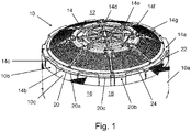
- Fig. 1 shows a schematic perspective view of an embodiment of a desiccant container 10 according to the invention for an air treatment device of a vehicle (both not shown).
- the desiccant container 10 is established for an air dryer cartridge 12 for a vehicle that is formed as an utility vehicle.
- the desiccant container 10 comprises a container housing 10a and a container cover 14.
- the container housing 10a forms a main body of the desiccant container 10.
- the container housing 10a is formed as a pot comprising a circular cross section and comprising, in a pre-mounted state, at least one container opening that is closed by the container cover 14 in a mounted state.
- the container cover 14 is substantially formed as a dome.
- the container housing 10a and the container cover 14 form, in the mounted state, an accommodation volume 16 for accommodating a desiccant 18.
- the desiccant 18 is formed by multiple loose desiccant beads (number of hundreds, thousands, ten thousands etc.) that are hold in space properly by the desiccant container 10.
- the desiccant 18 Due to the sufficiently small bead size (average bead diameter is ca. 1 mm to ca. 5 mm or to ca. 10 mm), the desiccant 18 has quasi-fluid characteristics.
- the container housing 10a and the container cover 14 are connected to each other by a material connection 20.
- this material connection 20 may be formed as an integral material connection.
- the material connection 20 is formed by at least one welded connection 20a.
- the material connection 20 may be also formed by at least one brazing connection or glue connection.
- the welded connection 20a is formed by an ultrasonic welded connection.
- the welded connection 20a is formed by a welded annular connection 20b.
- the container cover 14 and the container housing 10a are connected to each other at an annular connection region 22.
- connection region 22 is located at a top region 10b of the container housing 10a and at an outermost diameter region 14a of the container cover 14.
- the welded annular-shaped connection 20b is formed by a plurality of welded annular sections 20c being tangentially separated from each other at the annular connection region 22.
- the welded annular sections 20c are formed by radial protrusions 14b radially protruding from the outermost diameter region 14a of the container cover 14 that forms a connection ring 14c at this outermost diameter region 14a.
- these radial protrusions 14b are aligned with corresponding support and connection sections 10c having the same tangential and radial arrangement as the radial protrusions 14b at the annular connection region 22.
- the radial support and connection sections 10c in the mounted state, also protruding radially from an outer surface of the container housing 10a at the top region 10b of the container housing 10a.
- the radial support and connection sections 10c together with the radial protrusions 14b form the welded annular sections 20c in an aligned and mounted state at which the welded connection 20a between the container cover 14 and container housing 10a is established.
- annular connection region 22 comprises a plurality of air inlet flow channels 24.
- the air inlet flow channels 24 are formed as inlet slots and they are tangentially arranged between the radial support and connection sections 10c and the radial protrusions 14b of the container cover 14, i.e. between the welded annular sections 20c.
- the plurality of welded annular sections 20c and the air inlet flow channels 24 are arranged radially symmetrically with regard to a longitudinal axis of the container cover 14 and the container housing 10a.
- the container cover 14 further comprises a plurality of cover rips 14d being also arranged radially symmetrically with regard to a longitudinal axis of the container cover and the container housing.
- cover rips 14d extend in a star-shaped radial manner from the central point of the container cover 14 to the welded annular sections 20c.
- the number of cover rips 14d correspond to the number of welded annular sections 20c.
- the cover rips 14d are integrally connected by an inner cover stiffening ring 14e and an outer cover stiffening ring 14f being coaxially arranged to each other.
- the inner and outer cover stiffening ring 14e, 14f together with the cover rips 14d each form cover inlet slot sections 14g for guiding pressurized air from the container cover 14 into the desiccant 18.
- the present invention also relates to the air dryer cartridge 12 as mentioned above for an air treatment device (not shown in Fig. 1 ) for a utility vehicle comprising such a desiccant container 10 as mentioned above.
- an air treatment device not shown in Fig. 1
- a utility vehicle comprising such a desiccant container 10 as mentioned above.
- the present invention also relates to an air treatment device (not shown in Fig. 1 ) for a utility vehicle comprising such a desiccant container 10 as mentioned above and comprising such an air dryer cartridge 12 as mentioned above.
- an air treatment device (not shown in Fig. 1 ) for a utility vehicle comprising such a desiccant container 10 as mentioned above and comprising such an air dryer cartridge 12 as mentioned above.
- the arrows and/or arrow parts that are not associated with a reference sign do not have any contribution to the subject-matter of the desiccant container 10, the air dryer cartridge 12 and the air treatment device according to the present invention, respectively.
- Fig. 2 shows a schematic view of a sequence of multiple steps of an embodiment of an inventive method of manufacturing the desiccant container of Fig. 1 .
- the method for manufacturing a desiccant container 10 for an air dryer cartridge 12 as mentioned above for a utility vehicle comprising the following steps: According to a first Step S1, a container housing 10a of the desiccant container 10 is provided.
- a container cover 14 of the desiccant container 10 is provided.
- the container housing 10a and the container cover 14 form an accommodation volume 16 for accommodating a desiccant 18.
- a third step S3 the container housing 10a and the container cover 14 are connected to each other by a material connection 20.
- the material connection 20 especially may by formed as an integral material connection.
- the material connection 20 may be formed by a welded connection 20a, wherein the welded connection 20a may be formed by an ultrasonic welded connection.
- welded connection 20a may be formed by a welded and annular-shaped connection.
Landscapes
- Chemical & Material Sciences (AREA)
- Engineering & Computer Science (AREA)
- Chemical Kinetics & Catalysis (AREA)
- Analytical Chemistry (AREA)
- General Chemical & Material Sciences (AREA)
- Oil, Petroleum & Natural Gas (AREA)
- Transportation (AREA)
- Mechanical Engineering (AREA)
- Valves And Accessory Devices For Braking Systems (AREA)
Abstract
Description
- The present invention relates to a desiccant container for an air dryer cartridge for a vehicle, especially utility vehicle, with at least one container housing and with at least one container cover, wherein, in a mounted state, at least one accommodation volume for accommodating a desiccant is formed by the container housing and the container cover.
- Further, the present invention relates to an air dryer cartridge for an air treatment device for a vehicle, especially utility vehicle, with at least one desiccant container as mentioned above, and relates to an air treatment device for a vehicle, especially utility vehicle, with at least one desiccant container as well as with at least one air dryer cartridge as mentioned above, respectively.
- Additionally, the present invention relates to a method of manufacturing of the desiccant container as mentioned above.
- In the field of vehicles and especially utility vehicles, usually pneumatic systems are used for brakes, suspension and other auxiliary systems. The distribution of the air is handled by a multi-circuit protection valve that can divide the air provided by a compressor or the like, handle the different opening and closing pressures and the pressure limitation of each circuits together with a circuit protection.
- Before the pressurized air may be controlled or managed this way, an important measure is to dry this air (as it still contains humidity of the atmosphere) provided by the compressor. This drying procedure is established by a desiccant container included within an air dryer cartridge being arranged between the compressor and the multi-circuit protection valve and providing dried and de-oiled air to the multi-circuit protection valve.
- Such conventional desiccant containers and air dryer cartridges are already known in the prior art.
-
DE 3208561 A1 shows an air-drying device having a connection housing on which a cap-shaped container is mounted, which accommodates a drying agent cartridge. For ease of changing the drying agent cartridge, a clamping bracket is used, which is swivellably mounted on the housing and can be swivelled over the container and fixed there. -
DE 69210614 T2 discloses an air dryer control system in which the compressed air output of a compressor is dried by one of two air dryers connected in parallel. The purging and drying cycles of the air dryers are alternated by a timing and relay device. -
EP 0933117 A1 discloses a shuttle valve for a gas drying system that cleans and dries a stream of unpurified pressurized gas received from a source thereof and supplied to a pneumatic system that uses such a purified pressurized air. The valve includes a housing that connects a drying assembly to a structure that conveys the unpurified pressurized air to the drying assembly. -
US 5901464 A relates to a twin tower air drying system for cleaning and drying a stream of unpurified pressurized air including a centrifugal separator having a baffle horizontally disposed therein to generally separate the centrifugal chamber into an upper sub-chamber and a lower sub-chamber; a pair of cavities each containing desiccant media and a purge tube with a flapper valve thereover to close and restrict flow of air through the purge tube when air is flowing upwardly through the cavity, and to open and promote air flow through the purge tube when air is flowing downwardly through the cavity. -
US 5961698 A discloses a twin tower gas drying system for cleaning and drying a stream of unpurified pressurized gas received from a source thereof for use of a pneumatic system. The drying system includes a manifold block provided with the plurality of ports. A separator and sump are connected to such a block and to one of the ports for initially separating moisture and particulates from such stream of unpurified gas, and for directing the remainder of the stream to the one port in the block. - Basically, the desiccant of all air dryer cartridges needs to be pretensioned as, during the lifetime of the air dryer cartridge, vibrations caused by the powertrain and the operation of the vehicle generate wear and friction of the desiccant formed by multiple desiccant beads or balls staying in contact to each other. The mentioned vibrations cause friction, abrasion, wear, and powdering of the desiccant beads resulting in an overall volume loss of the desiccant (over a sufficient period of time) that has to be compensated by a tension or pressing force in order to generate stable desiccant conditions of the desiccant. According to the prior art, the desiccant pretension is working as follows: a desiccant cover is pushed downwards against the desiccant with its hole contacting surface by a compression spring supported by the air dryer housing and pressed against it. All of the desiccant beads were pushed downwards by the desiccant cover (compensation of the abrasion loss) in one pretension direction.
- This solution requires a large number of the components and place. Further, a relatively high spring force is needed in order to push the whole area of the desiccant cover downwards in order to contact the desiccant. As a consequence, mechanical stress in the affected parts is increased and usually a bayonet connection between the container cover and the container main body or housing is used to handle the relatively high spring force.
- It is therefore an object of the present invention to improve a desiccant container and an air dryer cartridge as mentioned above, in particular in that they are built up with less parts, weight, and building space and/or in that the overall design is simplified.
- This object is solved according to the present invention with a desiccant container according to the features of claim 1. Correspondingly, a desiccant container for an air dryer cartridge for a vehicle, especially utility vehicle, is provided with at least one container housing and with at least one container cover, wherein, in a mounted state, at least one accommodation volume for accommodating a desiccant is formed by the container housing and the container cover, and wherein the container housing and the container cover are connected to each other by at least one, especially integral, material connection.
- The invention is based on the basic idea that the current solution of connecting the container cover to the container main body or container housing, by providing a bayonet connection (according to the prior art), is replaced by a material connection. This approach is based on a smaller pretension area of the desiccant container cover resulting in less mechanical tensions such that the connection between the container cover and the container housing may be simplified as an alternative for the bayonet connection, for example by the material connection. In general, there a three basic connection types alone or in combination how to connect at least two separate construction parts to each other. The first connection type is a form-fit, wherein the second one is a force- or friction-fit and the third one is the material connection as mentioned above. The solution according to the prior art is based on a bayonet connection that is mainly based on a from-fit. The solution according to the invention now constitutes an integral material connection such that the container cover and the container housing, once they are connected this way, may be separated again merely by destruction. The new solution also provides a simplification of the cover and housing connection as well as a proper fixing and the provision of less parts.
- Additionally, the material connection is formed by at least one welded connection. Weld connections provide a very strong connection on the one hand. On the other hand, such welded connections may be separated merely by destruction such that an unintended exchange of the desiccant itself (that is without the desiccant container) may be prevented. Also, a unique desiccant container design may be provided that clearly differs from solutions of other producers such that less mistakes resulting from unintended mounting or maintenance occur and an easy competitor distinction may be reached. Alternative material connections such as adhesive bonding or brazing are additionally conceivable.
- Besides, the welded connection is formed by at least one ultrasonic welded connection. Basically, the container housing and the container cover are made of plastic material for which ultrasonic welding is very advantageous. Ultrasonic welding is a very reliable, fast and cheap welding technique on the one hand. Further, ultrasonic welding provides less warping of the parts to be connected resulting in less mechanical tensions in the container housing and the container cover. Also, a very stable connection is provided.
- Moreover, the welded connection is formed by at least one welded annular connection. As the container housing as a main container body and the container cover are formed as parts with a substantially circular cross section, an annular-shaped weld connection is most advantageous for such geometries. To this end, the container housing is formed like a pot, wherein the container cover is formed like a dome. Further, the welded connection is formed at a radially outermost region of the container housing and the container cover, respectively.
- Further, the welded annular connection is formed by a plurality of welded annular sections. As the welded annular connection is divided into several welded annular sections, the welding effort as well as the material effort decreases. Further, the manufacturing time of the desiccant container may be accelerated together with a decreased construction space and weight.
- On the other hand, the container housing and the container cover are connected to each other by at least one annular connection region, wherein a plurality of air inlet flow channels are arranged at the annular connection region. According to the prior art, a bayonet connection is arranged at the annular connection region such that a plurality of inlet flow channels may not be positioned in such a region. Therefore, this design according to the invention increases the effective inlet flow area of the container cover such that the overall flow resistance decreases resulting in a more efficient desiccant container. On the other hand, the increase of the overall inlet flow area together with a reduction of the overall building space of the desiccant container results in an even more effective container. The inlet flow channels are formed as slots extending in annular sections.
- In addition, the plurality of welded annular sections and/or the air inlet flow channels are arranged radially symmetrically with regard to a longitudinal axis of the container cover and/or the container housing. This design increases an overall stiffness of the desiccant container while simultaneously the mechanical tensions within the container housing and the container cover may be reduced. Due to the stiffer design, less material may be needed resulting in a desiccant container, which has less weight, construction space and material effort. Preferably, the plurality of welded annular sections and the air inlet flow channels are arranged radially symmetrically with regard to a longitudinal axis of the container cover and the container housing.
- Especially, the container cover comprises a plurality of cover rips being arranged radially symmetrically with regard to a longitudinal axis of the container cover and/or the container housing. This design further increases the overall stiffness of the container cover while simultaneously the mechanical tensions within the cover body may be reduced. Due to the stiffer design, less material may be needed resulting in a container cover having less weight, construction space and material effort.
- Furthermore, the present invention also relates to an air dryer cartridge for an air treatment device for a vehicle, especially utility vehicle, with at least one desiccant container as mentioned above. The advantages and technical teachings as discussed with regard to the desiccant container and its embodiments as mentioned above, which is a sub-unit of the air dryer cartridge, are also transferable to the air dryer cartridge and its embodiments accordingly.
- Additionally, the present invention relates to an air treatment device for a vehicle, especially utility vehicle, with at least one desiccant container as mentioned above and with at least one air dryer cartridge as mentioned above. The advantages and technical teachings as discussed above with regard to the desiccant container and the air dryer cartridge together with their embodiments, which are sub-units of the air treatment device, are also transferable to the air treatment device and its embodiments accordingly.
- According to the invention, additionally a method for manufacturing at least one desiccant container for an air dryer cartridge for a vehicle, especially utility vehicle, is provided, comprising the following steps:
- providing at least one container housing of the desiccant container;
- providing at least one container cover of the desiccant container, wherein, in a mounted state, at least one accommodation volume for accommodating a desiccant is formed by the container housing and the container cover; and
- connecting the container housing and the container cover to each other by at least one, especially integral, material connection.
- The advantages and technical teachings as discussed above with regard to the desiccant container and its embodiments are also transferable to the method for manufacturing at least one desiccant container and its embodiments accordingly.
- Consequently, the method may be established by forming the material connection by at least one welded connection.
- Further, the method may be established by forming the welded connection by at least one ultrasonic welded connection.
- Alternatively or additionally, the method may be established by forming the welded connection by at least one welded annular connection.
- Further details and advantages of the present invention shall now be disclosed in an embodiment according to the invention in connection with the drawings.
- It is shown in
- Fig. 1
- a schematic perspective view of an embodiment of a desiccant container according to the invention for an air treatment device of a vehicle; and
- Fig. 2
- schematic view of sequence of steps of an embodiment of an inventive method of manufacturing the desiccant container of
Fig. 1 . -
Fig. 1 shows a schematic perspective view of an embodiment of adesiccant container 10 according to the invention for an air treatment device of a vehicle (both not shown). - The
desiccant container 10 is established for anair dryer cartridge 12 for a vehicle that is formed as an utility vehicle. - The
desiccant container 10 comprises acontainer housing 10a and acontainer cover 14. - The
container housing 10a forms a main body of thedesiccant container 10. - Further, the
container housing 10a is formed as a pot comprising a circular cross section and comprising, in a pre-mounted state, at least one container opening that is closed by thecontainer cover 14 in a mounted state. - The
container cover 14 is substantially formed as a dome. - According to
Fig. 1 , thecontainer housing 10a and thecontainer cover 14 form, in the mounted state, anaccommodation volume 16 for accommodating adesiccant 18. - The
desiccant 18 is formed by multiple loose desiccant beads (number of hundreds, thousands, ten thousands etc.) that are hold in space properly by thedesiccant container 10. - Due to the sufficiently small bead size (average bead diameter is ca. 1 mm to ca. 5 mm or to ca. 10 mm), the
desiccant 18 has quasi-fluid characteristics. - The
container housing 10a and thecontainer cover 14 are connected to each other by amaterial connection 20. - Especially, this
material connection 20 may be formed as an integral material connection. - Further, the
material connection 20 is formed by at least one weldedconnection 20a. - Alternatively or additionally, the
material connection 20 may be also formed by at least one brazing connection or glue connection. - The welded
connection 20a, in turn, is formed by an ultrasonic welded connection. - Especially, other welded connections like high frequency welding, circular welding, rotary friction welding, or vibration welding are also conceivable in this regard.
- As can be depicted by
Fig. 1 , the weldedconnection 20a is formed by a weldedannular connection 20b. - The
container cover 14 and thecontainer housing 10a are connected to each other at anannular connection region 22. - This
connection region 22 is located at atop region 10b of thecontainer housing 10a and at anoutermost diameter region 14a of thecontainer cover 14. - The welded annular-shaped
connection 20b is formed by a plurality of weldedannular sections 20c being tangentially separated from each other at theannular connection region 22. - The welded
annular sections 20c are formed byradial protrusions 14b radially protruding from theoutermost diameter region 14a of thecontainer cover 14 that forms aconnection ring 14c at thisoutermost diameter region 14a. - Additionally, these
radial protrusions 14b are aligned with corresponding support andconnection sections 10c having the same tangential and radial arrangement as theradial protrusions 14b at theannular connection region 22. - The radial support and
connection sections 10c, in the mounted state, also protruding radially from an outer surface of thecontainer housing 10a at thetop region 10b of thecontainer housing 10a. - Thus, the radial support and
connection sections 10c together with theradial protrusions 14b form the weldedannular sections 20c in an aligned and mounted state at which the weldedconnection 20a between thecontainer cover 14 andcontainer housing 10a is established. - Further, the
annular connection region 22 comprises a plurality of airinlet flow channels 24. - The air
inlet flow channels 24 are formed as inlet slots and they are tangentially arranged between the radial support andconnection sections 10c and theradial protrusions 14b of thecontainer cover 14, i.e. between the weldedannular sections 20c. - The plurality of welded
annular sections 20c and the airinlet flow channels 24 are arranged radially symmetrically with regard to a longitudinal axis of thecontainer cover 14 and thecontainer housing 10a. - The
container cover 14 further comprises a plurality of cover rips 14d being also arranged radially symmetrically with regard to a longitudinal axis of the container cover and the container housing. - These cover rips 14d extend in a star-shaped radial manner from the central point of the
container cover 14 to the weldedannular sections 20c. - That is, the number of cover rips 14d correspond to the number of welded
annular sections 20c. - These cover rips 14d radially terminate at the radial origin of the welded
annular sections 20c and terminate there at a tangential central point of these weldedannular sections 20c. - The cover rips 14d are integrally connected by an inner
cover stiffening ring 14e and an outercover stiffening ring 14f being coaxially arranged to each other. - The inner and outer
cover stiffening ring inlet slot sections 14g for guiding pressurized air from thecontainer cover 14 into thedesiccant 18. - Radially between the outer
cover stiffening ring 14g and theconnection region 22, there is arranged a plurality of cover inlet flow holes 14g for guiding pressurized air from thecontainer cover 14 into thedesiccant 18. - These plurality of cover
inlet flow holes 14g are tangentially separated from each other by the cover rips 14d. - Furthermore, the present invention also relates to the
air dryer cartridge 12 as mentioned above for an air treatment device (not shown inFig. 1 ) for a utility vehicle comprising such adesiccant container 10 as mentioned above. The advantages and technical teachings as discussed with regard to thedesiccant container 10 and its embodiments as mentioned above, which is a sub-unit of theair dryer cartridge 12, are also transferable to theair dryer cartridge 12 and its embodiments accordingly. - Additionally, the present invention also relates to an air treatment device (not shown in
Fig. 1 ) for a utility vehicle comprising such adesiccant container 10 as mentioned above and comprising such anair dryer cartridge 12 as mentioned above. The advantages and technical teachings as discussed with regard to the desiccant container and the air dryer cartridge together with its embodiments as mentioned above, which are sub-units of the air treatment device, are also transferable to the air treatment device and its embodiments accordingly. - The arrows and/or arrow parts that are not associated with a reference sign do not have any contribution to the subject-matter of the
desiccant container 10, theair dryer cartridge 12 and the air treatment device according to the present invention, respectively. -
Fig. 2 shows a schematic view of a sequence of multiple steps of an embodiment of an inventive method of manufacturing the desiccant container ofFig. 1 . - The method for manufacturing a
desiccant container 10 for anair dryer cartridge 12 as mentioned above for a utility vehicle comprising the following steps:
According to a first Step S1, acontainer housing 10a of thedesiccant container 10 is provided. - According to a second step S2, a
container cover 14 of thedesiccant container 10 is provided. - Besides, in a mounted state, the
container housing 10a and thecontainer cover 14 form anaccommodation volume 16 for accommodating adesiccant 18. - According to a third step S3, the
container housing 10a and thecontainer cover 14 are connected to each other by amaterial connection 20. - The
material connection 20 especially may by formed as an integral material connection. - Further, the
material connection 20 may be formed by a weldedconnection 20a, wherein the weldedconnection 20a may be formed by an ultrasonic welded connection. - Additionally, the welded
connection 20a may be formed by a welded and annular-shaped connection. -
- 10
- desiccant container
- 10a
- container housing
- 10b
- top region of the container housing
- 10c
- radial support and connection sections
- 12
- dryer cartridge
- 14
- container cover
- 14a
- outermost diameter region
- 14b
- radial protrusions
- 14c
- connection ring
- 14d
- cover rips
- 14e
- inner cover stiffening ring
- 14f
- outer cover stiffening ring
- 14g
- cover inlet flow slot sections
- 16
- accommodation volume
- 18
- desiccant
- 20
- material connection
- 20a
- welded connection
- 20b
- welded annular connection
- 20c
- welded annular sections
- 22
- connection region
- 24
- air inlet flow channels
- S1
- first step
- S2
- second step
- S3
- third step
Claims (14)
- A desiccant container (10) for an air dryer cartridge (12) for a vehicle, especially utility vehicle, with at least one container housing (10a) and with at least one container cover (14), wherein, in a mounted state, at least one accommodation volume (16) for accommodating a desiccant (18) is formed by the container housing (10a) and the container cover (14), and wherein the container housing (10a) and the container cover (14) are connected to each other by at least one, especially integral, material connection (20).
- The desiccant container (10) according to claim 1,
characterized in that
the material connection (20) is formed by at least one welded connection (20a). - The desiccant container (10) according to claim 2,
characterized in that
the welded connection (20a) is formed by at least one ultrasonic welded connection. - The desiccant container (10) according to claim 2 or claim 3,
characterized in that
the welded connection (20a) is formed by at least one welded annular connection (20b). - The desiccant container (10) according to claim 4,
characterized in that
the welded annular connection (20b) is formed by a plurality of welded annular sections (20c). - The desiccant container (10) according to one of the preceding claims,
characterized in that
the container housing (10a) and the container cover (14) are connected to each other by at least one annular connection region (22), wherein a plurality of air inlet flow channels (24) are arranged at the annular connection region (22). - The desiccant container (10) according to claim 5 or claim 6,
characterized in that
the plurality of welded annular sections (20c) and/or the air inlet flow channels (24) are arranged radially symmetrically with regard to a longitudinal axis of the container cover (14) and/or the container housing (10a). - The desiccant container (10) according to one of the preceding claims,
characterized in that
the container cover (14) comprises a plurality of cover rips (14d) being arranged radially symmetrically with regard to a longitudinal axis of the container cover (14) and/or the container housing (10a). - An air dryer cartridge (12) for an air treatment device for a vehicle, especially utility vehicle, with at least one desiccant container (10) according to one of the preceding claims.
- An air treatment device for a vehicle, especially utility vehicle, with at least one desiccant container (10) according to one of the preceding claims 1 to 8 and with at least one air dryer cartridge (12) according to claim 9.
- Method for manufacturing at least one desiccant container (10) for an air dryer cartridge (12) for a vehicle, especially utility vehicle, comprising the following steps:- providing at least one container housing (10a) of the desiccant container (10);- providing at least one container cover (14) of the desiccant container (10), wherein, in a mounted state, at least one accommodation volume (16) for accommodating a desiccant (18) is formed by the container housing (10a) and the container cover (14); and- connecting the container housing (10a) and the container cover (14) to each other by at least one, especially integral, material connection (20).
- Method according to claim 11,
characterized by
forming the material connection (20) by at least one welded connection (20a). - Method according to claim 12,
characterized by
forming the welded connection (20a) by at least one ultrasonic welded connection. - Method according to claim 12 or claim 13,
characterized by
forming the welded connection (20a) by at least one welded annular connection (20b).
Priority Applications (3)
| Application Number | Priority Date | Filing Date | Title |
|---|---|---|---|
| EP20213941.6A EP4011482A1 (en) | 2020-12-14 | 2020-12-14 | Desiccant container, air dryer cartridge, air treatment device, and method of manufacturing of a desiccant container |
| PCT/EP2021/081597 WO2022128279A1 (en) | 2020-12-14 | 2021-11-12 | Desiccant container |
| CN202180084295.3A CN116761661A (en) | 2020-12-14 | 2021-11-12 | Desiccant container |
Applications Claiming Priority (1)
| Application Number | Priority Date | Filing Date | Title |
|---|---|---|---|
| EP20213941.6A EP4011482A1 (en) | 2020-12-14 | 2020-12-14 | Desiccant container, air dryer cartridge, air treatment device, and method of manufacturing of a desiccant container |
Publications (1)
| Publication Number | Publication Date |
|---|---|
| EP4011482A1 true EP4011482A1 (en) | 2022-06-15 |
Family
ID=73835527
Family Applications (1)
| Application Number | Title | Priority Date | Filing Date |
|---|---|---|---|
| EP20213941.6A Pending EP4011482A1 (en) | 2020-12-14 | 2020-12-14 | Desiccant container, air dryer cartridge, air treatment device, and method of manufacturing of a desiccant container |
Country Status (3)
| Country | Link |
|---|---|
| EP (1) | EP4011482A1 (en) |
| CN (1) | CN116761661A (en) |
| WO (1) | WO2022128279A1 (en) |
Citations (12)
| Publication number | Priority date | Publication date | Assignee | Title |
|---|---|---|---|---|
| DE3208561A1 (en) | 1982-03-10 | 1983-09-15 | Robert Bosch Gmbh, 7000 Stuttgart | Pneumatic system |
| US4673420A (en) * | 1986-02-10 | 1987-06-16 | Haker Leroy C | Desiccant dryer |
| DE69210614T2 (en) | 1991-08-20 | 1996-10-10 | Allied Signal Inc | COMPRESSED AIR SYSTEM WITH TWO AIR DRYERS |
| US5901464A (en) | 1997-11-26 | 1999-05-11 | Westinghouse Air Brake Company | E-1 twin tower air dryer for an air compressor unit |
| EP0933117A1 (en) | 1998-02-02 | 1999-08-04 | Westinghouse Air Brake Company | Shuttle valve for twin tower air dryer |
| US5961698A (en) | 1998-02-02 | 1999-10-05 | Westinghouse Air Brake Company | Twin tower air dryer |
| EP1042009A1 (en) * | 1997-12-23 | 2000-10-11 | Steris Corporation | Antimicrobial composition delivery system with an integrated filter |
| US20100294273A1 (en) * | 2009-05-22 | 2010-11-25 | 3M Innovative Properties Company | Filter cartridge having location-registered view window for end-of-service-life-indicator (esli) |
| US20140360891A1 (en) * | 2013-03-12 | 2014-12-11 | Bret E. Kline | System and method for using adsorbent/absorbent in loading, storing, delivering, and retrieving gases, fluids, and liquids |
| EP3012009A1 (en) * | 2013-06-21 | 2016-04-27 | Mitsubishi Gas Chemical Company, Inc. | Container containing absorbent |
| EP3392201A1 (en) * | 2012-03-20 | 2018-10-24 | Brita GmbH | Method of manufacturing a cartridge for a fluid treatment system and corrasponding cartridge |
| EP3398672A1 (en) * | 2017-05-02 | 2018-11-07 | WABCO Europe BVBA | Drying agent cartridge for an air treatment system as well as air treatment system for a commercial vehicle |
-
2020
- 2020-12-14 EP EP20213941.6A patent/EP4011482A1/en active Pending
-
2021
- 2021-11-12 WO PCT/EP2021/081597 patent/WO2022128279A1/en active Application Filing
- 2021-11-12 CN CN202180084295.3A patent/CN116761661A/en active Pending
Patent Citations (12)
| Publication number | Priority date | Publication date | Assignee | Title |
|---|---|---|---|---|
| DE3208561A1 (en) | 1982-03-10 | 1983-09-15 | Robert Bosch Gmbh, 7000 Stuttgart | Pneumatic system |
| US4673420A (en) * | 1986-02-10 | 1987-06-16 | Haker Leroy C | Desiccant dryer |
| DE69210614T2 (en) | 1991-08-20 | 1996-10-10 | Allied Signal Inc | COMPRESSED AIR SYSTEM WITH TWO AIR DRYERS |
| US5901464A (en) | 1997-11-26 | 1999-05-11 | Westinghouse Air Brake Company | E-1 twin tower air dryer for an air compressor unit |
| EP1042009A1 (en) * | 1997-12-23 | 2000-10-11 | Steris Corporation | Antimicrobial composition delivery system with an integrated filter |
| EP0933117A1 (en) | 1998-02-02 | 1999-08-04 | Westinghouse Air Brake Company | Shuttle valve for twin tower air dryer |
| US5961698A (en) | 1998-02-02 | 1999-10-05 | Westinghouse Air Brake Company | Twin tower air dryer |
| US20100294273A1 (en) * | 2009-05-22 | 2010-11-25 | 3M Innovative Properties Company | Filter cartridge having location-registered view window for end-of-service-life-indicator (esli) |
| EP3392201A1 (en) * | 2012-03-20 | 2018-10-24 | Brita GmbH | Method of manufacturing a cartridge for a fluid treatment system and corrasponding cartridge |
| US20140360891A1 (en) * | 2013-03-12 | 2014-12-11 | Bret E. Kline | System and method for using adsorbent/absorbent in loading, storing, delivering, and retrieving gases, fluids, and liquids |
| EP3012009A1 (en) * | 2013-06-21 | 2016-04-27 | Mitsubishi Gas Chemical Company, Inc. | Container containing absorbent |
| EP3398672A1 (en) * | 2017-05-02 | 2018-11-07 | WABCO Europe BVBA | Drying agent cartridge for an air treatment system as well as air treatment system for a commercial vehicle |
Also Published As
| Publication number | Publication date |
|---|---|
| CN116761661A (en) | 2023-09-15 |
| WO2022128279A1 (en) | 2022-06-23 |
Similar Documents
| Publication | Publication Date | Title |
|---|---|---|
| US8500885B2 (en) | Air drier for air suspension of vehicle | |
| KR900003680B1 (en) | Air dryer apparatus for use with pneumatic operative device | |
| US6951581B2 (en) | Spin-on desiccant cartridge with integral oil removal filter | |
| JP2022183172A5 (en) | vehicle | |
| US7691163B2 (en) | Vehicle air dryer | |
| EP1945488B1 (en) | Air dryer system | |
| JP5298922B2 (en) | Vehicle air suspension dryer | |
| US8118911B2 (en) | Air drying arrangement | |
| EP4011482A1 (en) | Desiccant container, air dryer cartridge, air treatment device, and method of manufacturing of a desiccant container | |
| WO2007060883A1 (en) | Air drier | |
| EP4001035B1 (en) | Desiccant container, air dryer cartridge, air treatment device, and stackable device | |
| EP4029747B1 (en) | Air dryer device and air treatment device | |
| EP4026603A1 (en) | Desiccant container, air dryer cartridge and air treatment device | |
| US9259681B2 (en) | Air dryer | |
| WO2007060882A1 (en) | Air drier | |
| US20240066458A1 (en) | Sealing Interface, Air Dryer Cartridge and Air Treatment Device | |
| US20240033678A1 (en) | Fixing Interface, Air Dryer Cartridge and Air Treatment Device | |
| EP4026605A1 (en) | Fixing interface, air dryer cartridge and air treatment device | |
| JP4023864B2 (en) | Air dryer device | |
| EP4296128A1 (en) | Positioning and mounting interface, a desiccant cartridge and an air control device | |
| WO2023062408A1 (en) | Integrated twin air-dryer cartridge | |
| JP2017113685A (en) | Air suspension dryer |
Legal Events
| Date | Code | Title | Description |
|---|---|---|---|
| PUAI | Public reference made under article 153(3) epc to a published international application that has entered the european phase |
Free format text: ORIGINAL CODE: 0009012 |
|
| STAA | Information on the status of an ep patent application or granted ep patent |
Free format text: STATUS: THE APPLICATION HAS BEEN PUBLISHED |
|
| AK | Designated contracting states |
Kind code of ref document: A1 Designated state(s): AL AT BE BG CH CY CZ DE DK EE ES FI FR GB GR HR HU IE IS IT LI LT LU LV MC MK MT NL NO PL PT RO RS SE SI SK SM TR |
|
| STAA | Information on the status of an ep patent application or granted ep patent |
Free format text: STATUS: REQUEST FOR EXAMINATION WAS MADE |
|
| 17P | Request for examination filed |
Effective date: 20221214 |
|
| RBV | Designated contracting states (corrected) |
Designated state(s): AL AT BE BG CH CY CZ DE DK EE ES FI FR GB GR HR HU IE IS IT LI LT LU LV MC MK MT NL NO PL PT RO RS SE SI SK SM TR |
|
| RAP3 | Party data changed (applicant data changed or rights of an application transferred) |
Owner name: KNORR-BREMSE SYSTEME FUER NUTZFAHRZEUGE GMBH |