EP4011460A1 - Ullage pressure-driven valve for fire suppression - Google Patents
Ullage pressure-driven valve for fire suppression Download PDFInfo
- Publication number
- EP4011460A1 EP4011460A1 EP21210654.6A EP21210654A EP4011460A1 EP 4011460 A1 EP4011460 A1 EP 4011460A1 EP 21210654 A EP21210654 A EP 21210654A EP 4011460 A1 EP4011460 A1 EP 4011460A1
- Authority
- EP
- European Patent Office
- Prior art keywords
- feed port
- port
- actuation chamber
- container
- ullage
- Prior art date
- Legal status (The legal status is an assumption and is not a legal conclusion. Google has not performed a legal analysis and makes no representation as to the accuracy of the status listed.)
- Granted
Links
Images
Classifications
-
- A—HUMAN NECESSITIES
- A62—LIFE-SAVING; FIRE-FIGHTING
- A62C—FIRE-FIGHTING
- A62C37/00—Control of fire-fighting equipment
- A62C37/36—Control of fire-fighting equipment an actuating signal being generated by a sensor separate from an outlet device
- A62C37/38—Control of fire-fighting equipment an actuating signal being generated by a sensor separate from an outlet device by both sensor and actuator, e.g. valve, being in the danger zone
- A62C37/40—Control of fire-fighting equipment an actuating signal being generated by a sensor separate from an outlet device by both sensor and actuator, e.g. valve, being in the danger zone with electric connection between sensor and actuator
-
- A—HUMAN NECESSITIES
- A62—LIFE-SAVING; FIRE-FIGHTING
- A62C—FIRE-FIGHTING
- A62C35/00—Permanently-installed equipment
- A62C35/02—Permanently-installed equipment with containers for delivering the extinguishing substance
- A62C35/023—Permanently-installed equipment with containers for delivering the extinguishing substance the extinguishing material being expelled by compressed gas, taken from storage tanks, or by generating a pressure gas
-
- A—HUMAN NECESSITIES
- A62—LIFE-SAVING; FIRE-FIGHTING
- A62C—FIRE-FIGHTING
- A62C35/00—Permanently-installed equipment
- A62C35/02—Permanently-installed equipment with containers for delivering the extinguishing substance
- A62C35/11—Permanently-installed equipment with containers for delivering the extinguishing substance controlled by a signal from the danger zone
- A62C35/13—Permanently-installed equipment with containers for delivering the extinguishing substance controlled by a signal from the danger zone with a finite supply of extinguishing material
-
- A—HUMAN NECESSITIES
- A62—LIFE-SAVING; FIRE-FIGHTING
- A62C—FIRE-FIGHTING
- A62C37/00—Control of fire-fighting equipment
- A62C37/36—Control of fire-fighting equipment an actuating signal being generated by a sensor separate from an outlet device
- A62C37/46—Construction of the actuator
-
- A—HUMAN NECESSITIES
- A62—LIFE-SAVING; FIRE-FIGHTING
- A62C—FIRE-FIGHTING
- A62C13/00—Portable extinguishers which are permanently pressurised or pressurised immediately before use
- A62C13/003—Extinguishers with spraying and projection of extinguishing agents by pressurised gas
-
- A—HUMAN NECESSITIES
- A62—LIFE-SAVING; FIRE-FIGHTING
- A62C—FIRE-FIGHTING
- A62C13/00—Portable extinguishers which are permanently pressurised or pressurised immediately before use
- A62C13/62—Portable extinguishers which are permanently pressurised or pressurised immediately before use with a single permanently pressurised container
- A62C13/64—Portable extinguishers which are permanently pressurised or pressurised immediately before use with a single permanently pressurised container the extinguishing material being released by means of a valve
-
- A—HUMAN NECESSITIES
- A62—LIFE-SAVING; FIRE-FIGHTING
- A62C—FIRE-FIGHTING
- A62C13/00—Portable extinguishers which are permanently pressurised or pressurised immediately before use
- A62C13/76—Details or accessories
Definitions
- Exemplary embodiments pertain to the art of fire suppression and, in particular, to an ullage pressure-driven valve for fire suppression.
- Fire detection and suppression is an important function in many areas, including on commercial ground vehicles.
- a fire suppression system may be employed to extinguish the fire.
- Fire suppression systems generally involve the rapid discharge of a fire suppression agent. While a hand-held fire extinguisher may be used in some applications, fire suppression agent may be dispersed via plumbing or tubing in other applications, such as in commercial ground vehicles.
- a fire suppression system in one embodiment, includes a feed port, and a channel to couple the feed port to an actuation chamber.
- a solenoid valve controllably blocks a connection between the feed port and the channel. Pressure from the feed port builds up in the actuation chamber based on the solenoid valve unblocking the connection.
- a piston is in communication with the actuation chamber, and an inlet port is closed off by a disc. The piston travels through the inlet port and burst the disc based on the pressure in the actuation chamber.
- An outlet port is coupled to the inlet port.
- the system also includes a container including a material and ullage, the ullage being space above the material in the container.
- the container is pressurized.
- the feed port is in communication with the ullage.
- pressure from the ullage is the pressure from the feed port that is channeled to the actuation chamber.
- the system also includes a siphon tube controllably coupled to the inlet port.
- the disc blocks communication between the siphon tube and the inlet port and the siphon tube reaches the material in the container.
- the siphon tube conveys the material from the container through the inlet port to the outlet port based on the piston bursting the disc.
- the piston includes a tip at a first end and a head, wider than the tip, at a second end opposite the first end.
- the tip bursts the disc and the head blocks entry of the material from the container and through the inlet port into the actuation chamber.
- the material is a fire suppression agent.
- the system also includes a controller to provide a signal to the solenoid value to unblock the connection between the feed port and the channel.
- a method of assembling a fire suppression system includes forming a feed port, and arranging a channel to couple the feed port to an actuation chamber. The method also includes configuring a solenoid valve to controllably block a connection between the feed port and the channel. Pressure from the feed port builds up in the actuation chamber based on the solenoid valve unblocking the connection.
- a piston is arranged in communication with the actuation chamber, and a disc is disposed to close off an inlet port. The piston travels through the inlet port and bursts the disc based on the pressure in the actuation chamber.
- An outlet port is coupled to the inlet port.
- the method also includes pressurizing a container that includes a material and ullage, the ullage being space above the material in the container.
- the forming the feed port includes arranging the feed port to be in communication with the ullage in the container.
- the method also includes disposing a filter between the feed port and the ullage to block the material from entering the feed port.
- the arranging the feed port includes creating a channel such that pressure from the ullage is the pressure from the feed port that is channeled to the actuation chamber.
- the method also includes controllably coupling a siphon tube to the inlet port, wherein the disc blocks communication between the siphon tube and the inlet port and the siphon tube reaches the material in the container.
- controllably coupling the siphon tube includes disposing the siphon tube such that the siphon tube conveys the material from the container through the inlet port to the outlet port based on the piston bursting the disc.
- the piston includes a tip at a first end and a head, wider than the tip, at a second end opposite the first end, and the arranging the piston includes aligning the tip to burst the disc and the head to block entry of the material from the container and through the inlet port into the actuation chamber.
- the material is a fire suppression agent.
- the method also includes coupling a controller to the solenoid valve. This provides a signal to the solenoid value to unblock the connection between the feed port and the channel.
- a fire suppression system discharges fire suppression agent to extinguish a fire.
- Prior fire suppression systems in certain applications involve activation of the discharge by direct explosive impingement energy.
- a device e.g., squib, cartridge
- a device e.g., squib, cartridge
- a dome-shaped burst disc at the opening of the container of fire suppression agent.
- the fire suppression agent which is under pressure, is rapidly discharged through a distribution system such as tubing with outlet nozzles.
- Embodiments of the systems and methods detailed herein relate to an ullage pressure-driven valve for fire suppression.
- a container e.g., cylinder, bottle
- ullage is the amount by which the container is unfilled with the material.
- ullage is understood to refer to the empty space (e.g., air) above the material in the container.
- the material in the container that gives rise to the ullage is fire suppression agent.
- the container is pressurized such that the ullage contains pressurized gas. Ullage pressure refers to this gas pressure.
- a device is no longer needed to provide explosive energy to rupture the burst disc. Instead, ullage pressure in the container that holds the fire suppression agent is directed to cause the release of a piston with a tip that pierces the scored burst disc, allowing the fire suppression agent to flow.
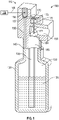
- FIG. 1 is a cross-sectional view of aspects of a fire suppression system 100 with an exemplary ullage pressure-driven valve 110 according to one or more embodiments.
- a fire suppression system 100 may include a fire extinguisher, controller 160, sensors that detect the overheat condition, and a distribution system for the first suppression agent 125.
- the valve 110 that is part of the fire extinguisher is detailed in FIGS. 1 and 2 .
- a container 120 e.g., cylinder
- the fire suppression agent 125 may be a potassium bicarbonate-based dry chemical, for example.
- the dry chemical takes the physical form of a powder similar to baking soda.
- the container 120 is pressurized and, thus, the ullage 130 is pressurized.
- a siphon tube 135 extends into the container 120, as shown in the exemplary embodiment. This siphon tube 135 is connected to an inlet port 185 of the valve 110. According to an alternate embodiment in which the fire suppression system 100 is inverted, the siphon tube 135 may not be needed.
- a disc 180 is disposed at the opening to the inlet port 185 to prevent the fire suppression agent from coming up through the inlet port 185 to the outlet port 190 until fire suppression is actuated.
- the disc 180 which may be referred to as a rupture disc or burst disc, for example, is a non-reclosing disc.
- the disc 180 is a burst disc of steel or nickel-bearing steel.
- the disc 180 may be scored according to exemplary embodiments.
- the disc 180 breaks open at a burst pressure to allow unrestricted flow of the fire suppression agent 125 via the siphon tube 135 and through the inlet port 185 into the outlet port 190 according to the mechanism detailed herein.
- a controller 160 provides a signal 165 to a solenoid valve 155.
- the solenoid valve 155 is an electromechanically operated valve that moves up according to the exemplary arrangement shown in FIG. 1 . However, according to alternate embodiments, the solenoid valve 155 may be arranged to rotate or move in a different direction based on the signal 165 from the controller 160.
- the controller 160 may provide the signal 165 based on a fire detection system or another input, for example.
- the movement of the solenoid valve 155 creates a path between the feed port 150 and the actuation chamber 170 that is blocked by the solenoid valve 155 in the closed position shown in FIG. 1 .
- the feed port 150 has an opening to the ullage 130 and is pressurized by ullage pressure.
- a filter 140 e.g., sintered disc
- the ullage pressure in the feed port 150 is channeled to the actuation chamber 170 via the channel 157.
- Pressure buildup in the actuation chamber 170 causes downward movement, according to the exemplary arrangement shown in FIG. 1 , of the piston 175.
- the head 173 of the piston 175 is the widest part of the piston 175, as shown. This portion holds in the ullage pressure that reaches the actuation chamber 170 until that pressure is high enough to actuate the piston 175.
- an O-ring may be placed around the head 173 of the piston 175. The O-ring creates a trapped volume in the actuation chamber 170 (i.e., prevents the leak of any pressure that is introduced via the channel 157) to ensure that the pressure buildup in the actuation chamber 170 is sufficient to act on the piston 175.
- the piston 175 has a sharp tip 177, which is at the opposite end as the head 173.
- the downward movement of the piston 175 caused by sufficient pressure buildup in the actuation chamber 170 results in the tip 177 bursting the disc 180.
- fire suppression agent 125 in the pressurized container 120 is forced up through the siphon tube 135 and inlet port 185 and out through the outlet port 190.
- the fire suppression agent 125 is channeled to the output port 190 based on the head 173 of the piston 175 blocking the path to the actuation chamber 170, as shown in FIG. 2 .
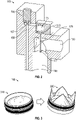
- FIG. 2 shows a cross-sectional view of an exemplary ullage pressure-driven valve 110 according to one or more embodiments.
- the view shown in FIG. 2 is of the position of the valve 110 after the disc 180 has been burst.
- the solenoid valve 155 is not blocking the connection between the channel 157 to the actuation chamber 170 and the feed port 150 with ullage pressure.
- the piston 175 is in the deployed position where the tip 177 has burst through the disc 180.
- the head 173 of the piston 175 has closed off the actuation chamber 170 from the inlet port 185.
- fire suppression agent 125 in the inlet port 185 is directed to the outlet port 190.
- FIG. 3 shows a disc 180 of an exemplary ullage pressure-driven valve 110 according to one or more embodiments.
- the disc 180 is shown in the intact state 310 and in the burst state 320. As FIG. 3 indicates, in the burst state 320, the disc 180 is open to allow flow of the fire suppression agent 125.
Landscapes
- Health & Medical Sciences (AREA)
- Public Health (AREA)
- Business, Economics & Management (AREA)
- Emergency Management (AREA)
- Fire-Extinguishing By Fire Departments, And Fire-Extinguishing Equipment And Control Thereof (AREA)
Abstract
Description
- Exemplary embodiments pertain to the art of fire suppression and, in particular, to an ullage pressure-driven valve for fire suppression.
- Fire detection and suppression is an important function in many areas, including on commercial ground vehicles. When an overheat condition such as a fire is detected, a fire suppression system may be employed to extinguish the fire. Fire suppression systems generally involve the rapid discharge of a fire suppression agent. While a hand-held fire extinguisher may be used in some applications, fire suppression agent may be dispersed via plumbing or tubing in other applications, such as in commercial ground vehicles.
- In one embodiment, a fire suppression system includes a feed port, and a channel to couple the feed port to an actuation chamber. A solenoid valve controllably blocks a connection between the feed port and the channel. Pressure from the feed port builds up in the actuation chamber based on the solenoid valve unblocking the connection. A piston is in communication with the actuation chamber, and an inlet port is closed off by a disc. The piston travels through the inlet port and burst the disc based on the pressure in the actuation chamber. An outlet port is coupled to the inlet port.
- Additionally or alternatively, in this or other embodiments, the system also includes a container including a material and ullage, the ullage being space above the material in the container.
- Additionally or alternatively, in this or other embodiments, the container is pressurized.
- Additionally or alternatively, in this or other embodiments, the feed port is in communication with the ullage.
- Additionally or alternatively, in this or other embodiments, pressure from the ullage is the pressure from the feed port that is channeled to the actuation chamber.
- Additionally or alternatively, in this or other embodiments, the system also includes a siphon tube controllably coupled to the inlet port. The disc blocks communication between the siphon tube and the inlet port and the siphon tube reaches the material in the container.
- Additionally or alternatively, in this or other embodiments, the siphon tube conveys the material from the container through the inlet port to the outlet port based on the piston bursting the disc.
- Additionally or alternatively, in this or other embodiments, the piston includes a tip at a first end and a head, wider than the tip, at a second end opposite the first end. The tip bursts the disc and the head blocks entry of the material from the container and through the inlet port into the actuation chamber.
- Additionally or alternatively, in this or other embodiments, the material is a fire suppression agent.
- Additionally or alternatively, in this or other embodiments, the system also includes a controller to provide a signal to the solenoid value to unblock the connection between the feed port and the channel.
- In another embodiment, a method of assembling a fire suppression system includes forming a feed port, and arranging a channel to couple the feed port to an actuation chamber. The method also includes configuring a solenoid valve to controllably block a connection between the feed port and the channel. Pressure from the feed port builds up in the actuation chamber based on the solenoid valve unblocking the connection. A piston is arranged in communication with the actuation chamber, and a disc is disposed to close off an inlet port. The piston travels through the inlet port and bursts the disc based on the pressure in the actuation chamber. An outlet port is coupled to the inlet port.
- Additionally or alternatively, in this or other embodiments, the method also includes pressurizing a container that includes a material and ullage, the ullage being space above the material in the container.
- Additionally or alternatively, in this or other embodiments, the forming the feed port includes arranging the feed port to be in communication with the ullage in the container.
- Additionally or alternatively, in this or other embodiments, the method also includes disposing a filter between the feed port and the ullage to block the material from entering the feed port.
- Additionally or alternatively, in this or other embodiments, the arranging the feed port includes creating a channel such that pressure from the ullage is the pressure from the feed port that is channeled to the actuation chamber.
- Additionally or alternatively, in this or other embodiments, the method also includes controllably coupling a siphon tube to the inlet port, wherein the disc blocks communication between the siphon tube and the inlet port and the siphon tube reaches the material in the container.
- Additionally or alternatively, in this or other embodiments, the controllably coupling the siphon tube includes disposing the siphon tube such that the siphon tube conveys the material from the container through the inlet port to the outlet port based on the piston bursting the disc.
- Additionally or alternatively, in this or other embodiments, the piston includes a tip at a first end and a head, wider than the tip, at a second end opposite the first end, and the arranging the piston includes aligning the tip to burst the disc and the head to block entry of the material from the container and through the inlet port into the actuation chamber.
- Additionally or alternatively, in this or other embodiments, the material is a fire suppression agent.
- Additionally or alternatively, in this or other embodiments, the method also includes coupling a controller to the solenoid valve. This provides a signal to the solenoid value to unblock the connection between the feed port and the channel.
- The following descriptions should not be considered limiting in any way. With reference to the accompanying drawings, like elements are numbered alike:
-
FIG. 1 is a cross-sectional view of aspects of a fire suppression system with an exemplary ullage pressure-driven valve according to one or more embodiments; -
FIG. 2 is a cross-sectional view of an exemplary ullage pressure-driven valve according to one or more embodiments; and -
FIG. 3 shows a disc of an exemplary ullage pressure-driven valve according to one or more embodiments. - A detailed description of one or more embodiments of the disclosed apparatus and method are presented herein by way of exemplification and not limitation with reference to the Figures.
- As previously noted, a fire suppression system discharges fire suppression agent to extinguish a fire. Prior fire suppression systems in certain applications involve activation of the discharge by direct explosive impingement energy. Specifically, upon receiving an electronic signal, a device (e.g., squib, cartridge) provides explosive energy that is focused on a dome-shaped burst disc at the opening of the container of fire suppression agent. When the burst disc is ruptured by the explosive impingement energy, the fire suppression agent, which is under pressure, is rapidly discharged through a distribution system such as tubing with outlet nozzles.
- Embodiments of the systems and methods detailed herein relate to an ullage pressure-driven valve for fire suppression. When material is added to a container (e.g., cylinder, bottle), ullage is the amount by which the container is unfilled with the material. Generally, ullage is understood to refer to the empty space (e.g., air) above the material in the container. According to the one or more embodiments, the material in the container that gives rise to the ullage is fire suppression agent. Further, the container is pressurized such that the ullage contains pressurized gas. Ullage pressure refers to this gas pressure. As described, a device is no longer needed to provide explosive energy to rupture the burst disc. Instead, ullage pressure in the container that holds the fire suppression agent is directed to cause the release of a piston with a tip that pierces the scored burst disc, allowing the fire suppression agent to flow.
-
FIG. 1 is a cross-sectional view of aspects of afire suppression system 100 with an exemplary ullage pressure-drivenvalve 110 according to one or more embodiments. Afire suppression system 100 may include a fire extinguisher,controller 160, sensors that detect the overheat condition, and a distribution system for thefirst suppression agent 125. Thevalve 110 that is part of the fire extinguisher is detailed inFIGS. 1 and2 . A container 120 (e.g., cylinder) is shown to include afire suppression agent 125 withullage 130 containing pressurized gas above. Thefire suppression agent 125 may be a potassium bicarbonate-based dry chemical, for example. The dry chemical takes the physical form of a powder similar to baking soda. Thecontainer 120 is pressurized and, thus, theullage 130 is pressurized. A siphontube 135 extends into thecontainer 120, as shown in the exemplary embodiment. This siphontube 135 is connected to aninlet port 185 of thevalve 110. According to an alternate embodiment in which thefire suppression system 100 is inverted, the siphontube 135 may not be needed. - A
disc 180 is disposed at the opening to theinlet port 185 to prevent the fire suppression agent from coming up through theinlet port 185 to theoutlet port 190 until fire suppression is actuated. Thedisc 180, which may be referred to as a rupture disc or burst disc, for example, is a non-reclosing disc. According to an exemplary embodiment, thedisc 180 is a burst disc of steel or nickel-bearing steel. Thedisc 180 may be scored according to exemplary embodiments. Thedisc 180 breaks open at a burst pressure to allow unrestricted flow of thefire suppression agent 125 via the siphontube 135 and through theinlet port 185 into theoutlet port 190 according to the mechanism detailed herein. - A
controller 160 provides asignal 165 to asolenoid valve 155. Thesolenoid valve 155 is an electromechanically operated valve that moves up according to the exemplary arrangement shown inFIG. 1 . However, according to alternate embodiments, thesolenoid valve 155 may be arranged to rotate or move in a different direction based on thesignal 165 from thecontroller 160. Thecontroller 160 may provide thesignal 165 based on a fire detection system or another input, for example. The movement of thesolenoid valve 155 creates a path between thefeed port 150 and theactuation chamber 170 that is blocked by thesolenoid valve 155 in the closed position shown inFIG. 1 . Thefeed port 150 has an opening to theullage 130 and is pressurized by ullage pressure. A filter 140 (e.g., sintered disc) may be disposed at the opening of thefeed port 150 to theullage 130 in order to prevent any of thefirst suppression agent 125 from entering thefeed port 150. - When the
solenoid valve 155 moves, based on thesignal 165 from thecontroller 160, the ullage pressure in thefeed port 150 is channeled to theactuation chamber 170 via thechannel 157. Pressure buildup in theactuation chamber 170 causes downward movement, according to the exemplary arrangement shown inFIG. 1 , of thepiston 175. Thehead 173 of thepiston 175 is the widest part of thepiston 175, as shown. This portion holds in the ullage pressure that reaches theactuation chamber 170 until that pressure is high enough to actuate thepiston 175. According to exemplary embodiments, an O-ring may be placed around thehead 173 of thepiston 175. The O-ring creates a trapped volume in the actuation chamber 170 (i.e., prevents the leak of any pressure that is introduced via the channel 157) to ensure that the pressure buildup in theactuation chamber 170 is sufficient to act on thepiston 175. - As shown, the
piston 175 has asharp tip 177, which is at the opposite end as thehead 173. The downward movement of thepiston 175 caused by sufficient pressure buildup in theactuation chamber 170 results in thetip 177 bursting thedisc 180. Once thedisc 180 is burst,fire suppression agent 125 in thepressurized container 120 is forced up through the siphontube 135 andinlet port 185 and out through theoutlet port 190. Thefire suppression agent 125 is channeled to theoutput port 190 based on thehead 173 of thepiston 175 blocking the path to theactuation chamber 170, as shown inFIG. 2 . -
FIG. 2 shows a cross-sectional view of an exemplary ullage pressure-drivenvalve 110 according to one or more embodiments. The view shown inFIG. 2 is of the position of thevalve 110 after thedisc 180 has been burst. Thus, thesolenoid valve 155 is not blocking the connection between thechannel 157 to theactuation chamber 170 and thefeed port 150 with ullage pressure. In addition, thepiston 175 is in the deployed position where thetip 177 has burst through thedisc 180. Thehead 173 of thepiston 175 has closed off theactuation chamber 170 from theinlet port 185. Thus,fire suppression agent 125 in theinlet port 185 is directed to theoutlet port 190. -
FIG. 3 shows adisc 180 of an exemplary ullage pressure-drivenvalve 110 according to one or more embodiments. Thedisc 180 is shown in theintact state 310 and in theburst state 320. AsFIG. 3 indicates, in theburst state 320, thedisc 180 is open to allow flow of thefire suppression agent 125. - The term "about" is intended to include the degree of error associated with measurement of the particular quantity based upon the equipment available at the time of filing the application.
- The terminology used herein is for the purpose of describing particular embodiments only and is not intended to be limiting of the present disclosure. As used herein, the singular forms "a", "an" and "the" are intended to include the plural forms as well, unless the context clearly indicates otherwise. It will be further understood that the terms "comprises" and/or "comprising," when used in this specification, specify the presence of stated features, integers, steps, operations, elements, and/or components, but do not preclude the presence or addition of one or more other features, integers, steps, operations, element components, and/or groups thereof.
- While the present disclosure has been described with reference to an exemplary embodiment or embodiments, it will be understood by those skilled in the art that various changes may be made and equivalents may be substituted for elements thereof without departing from the scope of the present disclosure. In addition, many modifications may be made to adapt a particular situation or material to the teachings of the present disclosure without departing from the essential scope thereof. Therefore, it is intended that the present disclosure not be limited to the particular embodiment disclosed as the best mode contemplated for carrying out this present disclosure, but that the present disclosure will include all embodiments falling within the scope of the claims.
Claims (15)
- A fire suppression system comprising:a feed port;a channel configured to couple the feed port to an actuation chamber;a solenoid valve configured to controllably block a connection between the feed port and the channel, wherein pressure from the feed port builds up in the actuation chamber based on the solenoid valve unblocking the connection;a piston in communication with the actuation chamber;an inlet port closed off by a disc, wherein the piston is configured to travel through the inlet port and burst the disc based on the pressure in the actuation chamber; andan outlet port coupled to the inlet port.
- The system according to claim 1, further comprising a container including a material and ullage, the ullage being space above the material in the container.
- The system according to claim 2, wherein the feed port is in communication with the ullage.
- The system according to claim 2 or 3, wherein pressure from the ullage is the pressure from the feed port that is channeled to the actuation chamber.
- The system according to any one of claims 2 to 4, wherein the container is pressurized.
- The system according to any one of claims 2 to 5, further comprising a siphon tube controllably coupled to the inlet port, wherein the disc blocks communication between the siphon tube and the inlet port and the siphon tube reaches the material in the container.
- The system according to claim 6, wherein the siphon tube conveys the material from the container through the inlet port to the outlet port based on the piston bursting the disc.
- The system according to claim 6, wherein the piston includes a tip at a first end and a head, wider than the tip, at a second end opposite the first end, wherein the tip is configured to burst the disc and the head is configured to block entry of the material from the container and through the inlet port into the actuation chamber.
- The system according to any one of claims 2 to 8, wherein the material is a fire suppression agent.
- The system according to any preceding claim, further comprising a controller configured to provide a signal to the solenoid value to unblock the connection between the feed port and the channel.
- A method of assembling a fire suppression system, the method comprising:forming a feed port;arranging a channel to couple the feed port to an actuation chamber;configuring a solenoid valve to controllably block a connection between the feed port and the channel, wherein pressure from the feed port builds up in the actuation chamber based on the solenoid valve unblocking the connection;arranging a piston in communication with the actuation chamber;disposing a disc to close off an inlet port, wherein the piston is configured to travel through the inlet port and burst the disc based on the pressure in the actuation chamber; andcoupling an outlet port to the inlet port.
- The method according to claim 11, further comprising pressurizing a container that includes a material and ullage, the ullage being space above the material in the container.
- The method according to claim 12, wherein the forming the feed port includes arranging the feed port to be in communication with the ullage in the container, and further comprising disposing a filter between the feed port and the ullage to block the material from entering the feed port.
- The method according to claim 13, wherein the arranging the feed port includes creating a channel such that pressure from the ullage is the pressure from the feed port that is channeled to the actuation chamber.
- The method according to claim 12, 13 or 14, further comprising controllably coupling a siphon tube to the inlet port, wherein the disc blocks communication between the siphon tube and the inlet port and the siphon tube reaches the material in the container, and wherein the piston includes a tip at a first end and a head, wider than the tip, at a second end opposite the first end, and the arranging the piston includes aligning the tip to burst the disc and the head to block entry of the material from the container and through the inlet port into the actuation chamber.
Applications Claiming Priority (1)
| Application Number | Priority Date | Filing Date | Title |
|---|---|---|---|
| US17/118,827 US11865385B2 (en) | 2020-12-11 | 2020-12-11 | Ullage pressure-driven valve for fire suppression |
Publications (2)
| Publication Number | Publication Date |
|---|---|
| EP4011460A1 true EP4011460A1 (en) | 2022-06-15 |
| EP4011460B1 EP4011460B1 (en) | 2026-04-29 |
Family
ID=78806293
Family Applications (1)
| Application Number | Title | Priority Date | Filing Date |
|---|---|---|---|
| EP21210654.6A Active EP4011460B1 (en) | 2020-12-11 | 2021-11-26 | Ullage pressure-driven valve for fire suppression |
Country Status (2)
| Country | Link |
|---|---|
| US (2) | US11865385B2 (en) |
| EP (1) | EP4011460B1 (en) |
Families Citing this family (1)
| Publication number | Priority date | Publication date | Assignee | Title |
|---|---|---|---|---|
| US11865385B2 (en) | 2020-12-11 | 2024-01-09 | Kidde Technologies, Inc. | Ullage pressure-driven valve for fire suppression |
Citations (2)
| Publication number | Priority date | Publication date | Assignee | Title |
|---|---|---|---|---|
| KR101212984B1 (en) * | 2011-06-02 | 2012-12-18 | 곽진초 | Smart head automatic Operating Means for Extinguisher |
| US20160008646A1 (en) * | 2014-07-11 | 2016-01-14 | Kidde Technologies, Inc. | Burst disc puncture pressure-imbalance actuator for a fire extinguisher |
Family Cites Families (19)
| Publication number | Priority date | Publication date | Assignee | Title |
|---|---|---|---|---|
| GB1567895A (en) * | 1978-04-26 | 1980-05-21 | Glover & Co Ltd T | Operating head for a fire extinguisher |
| GB2096299B (en) * | 1981-04-06 | 1986-02-19 | Rilett John W | Fluid containers |
| US4492103A (en) * | 1983-02-11 | 1985-01-08 | Bs&B Safety Systems, Inc. | Apparatus for manufacturing rupture disks |
| US4620598A (en) * | 1983-10-07 | 1986-11-04 | Reeder Frank F | Disposable fire extinguisher |
| FR2608720B1 (en) * | 1986-12-18 | 1989-03-03 | Electricite De France | MEMBRANE SAFETY DEVICE WITH ACTIVE UPSTREAM BLADE KNIFE |
| US4691736A (en) | 1986-12-03 | 1987-09-08 | Marotta Scientific Controls, Inc. | Valve for fire suppression |
| US5230531A (en) * | 1990-10-22 | 1993-07-27 | Oea, Inc. | Gas generator ignition assembly using a projectile |
| US5458202A (en) * | 1993-09-09 | 1995-10-17 | Systron Donner Corporation | Pressurized extinguishant release device with rolling diaphragm |
| US5615743A (en) * | 1994-05-24 | 1997-04-01 | Katsutoshi Matsumoto | Fire extinguisher |
| US6076610A (en) * | 1996-08-30 | 2000-06-20 | Zwergel; James C. | Vehicular fire extinguishing device |
| EP1767248A1 (en) * | 1999-03-31 | 2007-03-28 | Aerojet-General Corporation | Hybrid fire extinguisher |
| US6164383A (en) * | 1999-08-17 | 2000-12-26 | Thomas; Orrett H. | Fire extinguishing system for automotive vehicles |
| US7281672B2 (en) * | 2004-03-11 | 2007-10-16 | Kidde-Fenwal, Inc. | Dual burst disk |
| US7562670B1 (en) * | 2006-04-28 | 2009-07-21 | Jones H Stephen | Flat valve for orbital applications |
| US7703471B2 (en) * | 2007-05-25 | 2010-04-27 | Tsm Corporation | Single-action discharge valve |
| WO2009050847A1 (en) * | 2007-10-19 | 2009-04-23 | Hideo Yoshida | Fire extinguisher gas ejector |
| LU91581B1 (en) | 2009-06-24 | 2010-12-27 | Luxembourg Patent Co | A high pressure gas discharge valve for a fire-extinguishing or explosion preventing system. |
| US9539452B2 (en) | 2014-07-11 | 2017-01-10 | Kidde Technologies, Inc. | Rapid pressure diffusion actuator for a fire extinguisher |
| US11865385B2 (en) | 2020-12-11 | 2024-01-09 | Kidde Technologies, Inc. | Ullage pressure-driven valve for fire suppression |
-
2020
- 2020-12-11 US US17/118,827 patent/US11865385B2/en active Active
-
2021
- 2021-11-26 EP EP21210654.6A patent/EP4011460B1/en active Active
-
2023
- 2023-11-29 US US18/522,826 patent/US12186607B2/en active Active
Patent Citations (2)
| Publication number | Priority date | Publication date | Assignee | Title |
|---|---|---|---|---|
| KR101212984B1 (en) * | 2011-06-02 | 2012-12-18 | 곽진초 | Smart head automatic Operating Means for Extinguisher |
| US20160008646A1 (en) * | 2014-07-11 | 2016-01-14 | Kidde Technologies, Inc. | Burst disc puncture pressure-imbalance actuator for a fire extinguisher |
Also Published As
| Publication number | Publication date |
|---|---|
| US11865385B2 (en) | 2024-01-09 |
| EP4011460B1 (en) | 2026-04-29 |
| US20240091576A1 (en) | 2024-03-21 |
| US12186607B2 (en) | 2025-01-07 |
| US20220184437A1 (en) | 2022-06-16 |
Similar Documents
| Publication | Publication Date | Title |
|---|---|---|
| RU2564612C2 (en) | Methods and device for passive, non-electric two-stage fire suppression | |
| RU2493892C2 (en) | High-integrity fluid discharge device | |
| JP2911154B2 (en) | Method and apparatus for finely dispersing a fluid in a gaseous medium | |
| CN101711320B (en) | Single-action discharge valve | |
| CN102883782B (en) | valve | |
| EP2308567B1 (en) | Fire suppression system | |
| CN100418595C (en) | Valve element | |
| US12186607B2 (en) | Ullage pressure-driven valve for fire suppression | |
| JP2005185835A (en) | Fire extinguishing apparatus and method, especially fire extinguishing apparatus and method for cargo room of airplane | |
| WO2015131048A1 (en) | Suppression and isolation system | |
| CA2151420A1 (en) | Discharging fire and explosion suppressants | |
| US10561869B2 (en) | Mount de-actuated safety mechanism | |
| US3269310A (en) | Inflating apparatus | |
| US11117005B2 (en) | Device for dispensing a pressurized material | |
| US20040188103A1 (en) | Thermally activated fire suppression system | |
| KR102056472B1 (en) | Percussion device of auto fire extinguisher system and chain auto extinguisher containing the same | |
| EP4225452B1 (en) | Release valve for fire protection systems, fire protection system and relative activation method | |
| KR102122031B1 (en) | A Fire Extinguishing Apparatus for Aircraft Having two Engine and A Controlling Method Using Thereof | |
| US4362181A (en) | Pressure relief system | |
| DK173493B1 (en) | Process and apparatus for finely dispersing liquids or powders in a gaseous medium, preferably in air | |
| GB1568467A (en) | Fire extinguishers | |
| GB2431455A (en) | Fire extinguisher valve | |
| HK1233571A1 (en) | Method for supplying fire suppressing agent |
Legal Events
| Date | Code | Title | Description |
|---|---|---|---|
| PUAI | Public reference made under article 153(3) epc to a published international application that has entered the european phase |
Free format text: ORIGINAL CODE: 0009012 |
|
| STAA | Information on the status of an ep patent application or granted ep patent |
Free format text: STATUS: THE APPLICATION HAS BEEN PUBLISHED |
|
| AK | Designated contracting states |
Kind code of ref document: A1 Designated state(s): AL AT BE BG CH CY CZ DE DK EE ES FI FR GB GR HR HU IE IS IT LI LT LU LV MC MK MT NL NO PL PT RO RS SE SI SK SM TR |
|
| STAA | Information on the status of an ep patent application or granted ep patent |
Free format text: STATUS: REQUEST FOR EXAMINATION WAS MADE |
|
| 17P | Request for examination filed |
Effective date: 20221214 |
|
| RBV | Designated contracting states (corrected) |
Designated state(s): AL AT BE BG CH CY CZ DE DK EE ES FI FR GB GR HR HU IE IS IT LI LT LU LV MC MK MT NL NO PL PT RO RS SE SI SK SM TR |
|
| GRAP | Despatch of communication of intention to grant a patent |
Free format text: ORIGINAL CODE: EPIDOSNIGR1 |
|
| STAA | Information on the status of an ep patent application or granted ep patent |
Free format text: STATUS: GRANT OF PATENT IS INTENDED |
|
| RIC1 | Information provided on ipc code assigned before grant |
Ipc: A62C 13/76 20060101ALN20250409BHEP Ipc: A62C 13/64 20060101ALN20250409BHEP Ipc: A62C 13/00 20060101ALN20250409BHEP Ipc: A62C 35/02 20060101ALI20250409BHEP Ipc: A62C 35/13 20060101ALI20250409BHEP Ipc: A62C 37/46 20060101ALI20250409BHEP Ipc: A62C 37/40 20060101AFI20250409BHEP |
|
| RIC1 | Information provided on ipc code assigned before grant |
Ipc: A62C 13/76 20060101ALN20250414BHEP Ipc: A62C 13/64 20060101ALN20250414BHEP Ipc: A62C 13/00 20060101ALN20250414BHEP Ipc: A62C 35/02 20060101ALI20250414BHEP Ipc: A62C 35/13 20060101ALI20250414BHEP Ipc: A62C 37/46 20060101ALI20250414BHEP Ipc: A62C 37/40 20060101AFI20250414BHEP |
|
| INTG | Intention to grant announced |
Effective date: 20250425 |
|
| GRAJ | Information related to disapproval of communication of intention to grant by the applicant or resumption of examination proceedings by the epo deleted |
Free format text: ORIGINAL CODE: EPIDOSDIGR1 |
|
| STAA | Information on the status of an ep patent application or granted ep patent |
Free format text: STATUS: REQUEST FOR EXAMINATION WAS MADE |
|
| GRAP | Despatch of communication of intention to grant a patent |
Free format text: ORIGINAL CODE: EPIDOSNIGR1 |
|
| STAA | Information on the status of an ep patent application or granted ep patent |
Free format text: STATUS: GRANT OF PATENT IS INTENDED |
|
| INTC | Intention to grant announced (deleted) | ||
| INTG | Intention to grant announced |
Effective date: 20250909 |
|
| RIC1 | Information provided on ipc code assigned before grant |
Ipc: A62C 37/40 20060101AFI20250902BHEP Ipc: A62C 37/46 20060101ALI20250902BHEP Ipc: A62C 35/13 20060101ALI20250902BHEP Ipc: A62C 35/02 20060101ALI20250902BHEP Ipc: A62C 13/00 20060101ALN20250902BHEP Ipc: A62C 13/64 20060101ALN20250902BHEP Ipc: A62C 13/76 20060101ALN20250902BHEP |
|
| GRAJ | Information related to disapproval of communication of intention to grant by the applicant or resumption of examination proceedings by the epo deleted |
Free format text: ORIGINAL CODE: EPIDOSDIGR1 |
|
| STAA | Information on the status of an ep patent application or granted ep patent |
Free format text: STATUS: REQUEST FOR EXAMINATION WAS MADE |
|
| GRAP | Despatch of communication of intention to grant a patent |
Free format text: ORIGINAL CODE: EPIDOSNIGR1 |
|
| STAA | Information on the status of an ep patent application or granted ep patent |
Free format text: STATUS: GRANT OF PATENT IS INTENDED |
|
| INTC | Intention to grant announced (deleted) | ||
| RIC1 | Information provided on ipc code assigned before grant |
Ipc: A62C 37/40 20060101AFI20260109BHEP Ipc: A62C 37/46 20060101ALI20260109BHEP Ipc: A62C 35/13 20060101ALI20260109BHEP Ipc: A62C 35/02 20060101ALI20260109BHEP Ipc: A62C 13/00 20060101ALN20260109BHEP Ipc: A62C 13/64 20060101ALN20260109BHEP Ipc: A62C 13/76 20060101ALN20260109BHEP |
|
| INTG | Intention to grant announced |
Effective date: 20260121 |
|
| RIC1 | Information provided on ipc code assigned before grant |
Ipc: A62C 37/40 20060101AFI20260116BHEP Ipc: A62C 37/46 20060101ALI20260116BHEP Ipc: A62C 35/13 20060101ALI20260116BHEP Ipc: A62C 35/02 20060101ALI20260116BHEP Ipc: A62C 13/00 20060101ALN20260116BHEP Ipc: A62C 13/64 20060101ALN20260116BHEP Ipc: A62C 13/76 20060101ALN20260116BHEP |
|
| GRAS | Grant fee paid |
Free format text: ORIGINAL CODE: EPIDOSNIGR3 |
|
| GRAA | (expected) grant |
Free format text: ORIGINAL CODE: 0009210 |
|
| STAA | Information on the status of an ep patent application or granted ep patent |
Free format text: STATUS: THE PATENT HAS BEEN GRANTED |
|
| AK | Designated contracting states |
Kind code of ref document: B1 Designated state(s): AL AT BE BG CH CY CZ DE DK EE ES FI FR GB GR HR HU IE IS IT LI LT LU LV MC MK MT NL NO PL PT RO RS SE SI SK SM TR |
|
| REG | Reference to a national code |
Ref country code: CH Ref legal event code: F10 Free format text: ST27 STATUS EVENT CODE: U-0-0-F10-F00 (AS PROVIDED BY THE NATIONAL OFFICE) Effective date: 20260429 Ref country code: GB Ref legal event code: FG4D |