EP4011231A2 - Helmet fit system - Google Patents
Helmet fit system Download PDFInfo
- Publication number
- EP4011231A2 EP4011231A2 EP21213115.5A EP21213115A EP4011231A2 EP 4011231 A2 EP4011231 A2 EP 4011231A2 EP 21213115 A EP21213115 A EP 21213115A EP 4011231 A2 EP4011231 A2 EP 4011231A2
- Authority
- EP
- European Patent Office
- Prior art keywords
- helmet
- harness
- anchor
- channel
- tensioning mechanism
- Prior art date
- Legal status (The legal status is an assumption and is not a legal conclusion. Google has not performed a legal analysis and makes no representation as to the accuracy of the status listed.)
- Pending
Links
- 238000013459 approach Methods 0.000 description 3
- 241000217377 Amblema plicata Species 0.000 description 1
- 239000004677 Nylon Substances 0.000 description 1
- 239000004676 acrylonitrile butadiene styrene Substances 0.000 description 1
- 239000000853 adhesive Substances 0.000 description 1
- 230000001070 adhesive effect Effects 0.000 description 1
- 238000013037 co-molding Methods 0.000 description 1
- 238000005516 engineering process Methods 0.000 description 1
- 229920001778 nylon Polymers 0.000 description 1
- 239000004033 plastic Substances 0.000 description 1
- 229920003023 plastic Polymers 0.000 description 1
- 229920000642 polymer Polymers 0.000 description 1
- 239000004800 polyvinyl chloride Substances 0.000 description 1
- 238000003466 welding Methods 0.000 description 1
Images


Classifications
-
- A—HUMAN NECESSITIES
- A42—HEADWEAR
- A42B—HATS; HEAD COVERINGS
- A42B3/00—Helmets; Helmet covers ; Other protective head coverings
- A42B3/04—Parts, details or accessories of helmets
- A42B3/08—Chin straps or similar retention devices
-
- A—HUMAN NECESSITIES
- A42—HEADWEAR
- A42B—HATS; HEAD COVERINGS
- A42B3/00—Helmets; Helmet covers ; Other protective head coverings
- A42B3/04—Parts, details or accessories of helmets
- A42B3/10—Linings
- A42B3/14—Suspension devices
- A42B3/145—Size adjustment devices
-
- A—HUMAN NECESSITIES
- A42—HEADWEAR
- A42B—HATS; HEAD COVERINGS
- A42B3/00—Helmets; Helmet covers ; Other protective head coverings
- A42B3/32—Collapsible helmets; Helmets made of separable parts ; Helmets with movable parts, e.g. adjustable
- A42B3/324—Adjustable helmets
Definitions
- This application relates to helmets, and, more particularly, to adjustable fit systems for helmets.
- helmets may be made in various sizes, it is impractical to make a helmet for every head size. This is particularly the case for highly-specialized helmets, such as those used by fighter jet pilots. Accordingly, many helmets incorporate some form of fit adjustment. In modern helmets, this may take the form of an inner yoke or flexible frame with one or more parts that may be adjusted in length, such as with an adjustment wheel. Fit is important for comfort and for helmet stability, especially when used with helmet attachments such as various optics.
- a helmet fit system may be mounted in a helmet and include: a harness; a first anchor; a second anchor; a tensioning mechanism; and a cable passing from a first point of securement on the tensioning mechanism, around the first anchor, through the harness, and around the second anchor.
- the tensioning mechanism is not secured to any portion of the harness.
- the harness may define a channel, the cable passing through the channel.
- the channel may be defined by a cover plate secured over a portion of the harness.
- the tensioning mechanism may be a dial tensioner.
- the cable further passes from the second anchor, back through the harness, around the first anchor to a second point of securement on the tensioning mechanism.
- the harness may be adapted to conform to a head of a wearer of the helmet.
- the harness may define a plurality of webs defining one or more openings.
- the helmet fit system includes a fastening strip defining a plurality of fastening points, the harness being configured to secure to any of the fastening points.
- a helmet is adapted to secure around a head of a wearer and has an inner surface and an outer surface, the helmet defining a plane of symmetry.
- a helmet fit system is mounted to the helmet, the helmet fit system including: a harness; a first anchor mounted to the inner surface of the helmet on a first side of the plane of symmetry; a second anchor mounted to the inner surface of the helmet on a second side of the plane of symmetry opposite the first side; a tensioning mechanism mounted to the outer surface of the helmet on the first side of the plane of symmetry; and a cable passing from a first point of securement on the tensioning mechanism, around the first anchor, through the harness, and around the second anchor.
- the tensioning mechanism is a dial tensioner.
- the helmet defines a channel defined between the inner surface and the outer surface and offset from the plane of symmetry, the cable passing from the first point of securement on the tensioning mechanism, through the channel, and around the first anchor.
- the cable further passes from the second anchor, back through the harness, around the first anchor, through the channel, and to a second point of securement on the tensioning mechanism.
- the tensioning mechanism is offset from the plane of symmetry by at least 15 percent of a width of the helmet perpendicular to the plane of symmetry. In some embodiments, the tensioning mechanism is offset from the plane of symmetry by at least 20 percent of a width of the helmet perpendicular to the plane of symmetry.
- the harness defines a channel, the cable passing through the channel.
- the channel may be defined by a cover plate secured over a portion of the harness.
- the harness may be adapted to conform to a head of a wearer of the helmet.
- the harness may define a plurality of webs defining one or more openings.
- a fastening strip defining a plurality of fastening points may be secured to the inner surface of the helmet, the harness being configured to secure to any of the fastening points.
- the tensioning mechanism is not secured to harness by any structure other than the cable and the helmet.
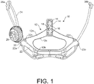
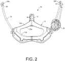
- a helmet fit system 10 may include a harness 12.
- the harness 12 may be a set of webs or straps that are intended to cradle the rear of a person's head when wearing a helmet.
- the harness 12 includes an upper web 12a and a lower web 12b defining an opening 12c between them.
- the harness 12 may be made of semi-rigid plastic such that the harness is able to flex to conform to the head of a wearer but does not significantly stretch during use (e.g., stretches less than 2 percent in length during use relative to when harness 12 is not being worn).
- the harness 12 may be made of nylon, polyvinyl chloride (PVC), acrylonitrile butadiene styrene (ABS), or other polymer.
- the harness 12 may attach to a helmet at one or more points.
- an attachment strip 14 secures to an inner rear surface of a helmet and defines a plurality of attachment points 16 arranged vertically.
- the harness 12 may include a barb 18 secured thereto, such as by co-molding.
- the barb 18 may be inserted into any of the attachment points 16 in order to attach the harness 12 to the helmet.
- the barb 18 may be removed in order to adjust the height of the harness 12 and may be configured such that the force required to remove is greater than the force required to insert within one of the attachment points 16.
- the vertical adjustability provided by the barb 18 and attachment points 16 is just one example of an adjustable attachment approach and any approach known in the art for attaching a harness 12 to a helmet may be used.
- the harness 12 is non-removably attached at one or more points to the harness 12, such as by rivets, welding, or other attachment means.
- the harness 12 may define a channel 20 extending across the harness 12 such that openings on either end of the channel 20 are separated along a generally horizontal path (e.g., within 15 degrees of horizontal) when worn.
- the channel 20 may be defined by a cover plate 22 secured to the harness 12, such as over the lower web 12b.
- the channel 20 may secure to the lower web 12b by means of welds, adhesive, rivets, or other fastening means.
- the lower web 12b may define two or more ridges such that the channel is defined between the ridges. Alternatively, one or more grooves may be defined in the lower web 12b such that channel 20 is defined between the cover plate 22 and the grooves.
- the channel 20 defined between the cover plate 22 and lower web 12b may include a height and a width that are both at least twice a diameter of a cable 24 passing through the channel 20 along its entire length. As will be discussed below, two lengths of a cable 24 may pass through the channel 20 such that in at least one dimension, the channel 20 is at least three times the diameter of the cable 24.
- multiple channels 20 may be defined between the cover plate 22 and the lower web 12b (e.g., multiple grooves in the web 12b or three ridges extending between the cover plate 22 and the lower web 12b). In this case, each channel 20 may have a cross section that is greater than the diameter of the cable 24 in two orthogonal directions.
- end portions of the cover plate 20 may be secured to the web 12b by means of rivets or other fasteners 22a, 22b, 22c, 22d in order to one or both of reinforce the channel 20 and provide a rounded region at the left and right entry points to facilitate sliding of the cable 24.
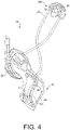
- the cable 24 may be tensioned by a tensioning assembly 26.
- the tensioning assembly may provide a mechanism to take up the cable 24 or pay out the cable 24 on order to adjust the relative position of the harness 12.
- the tensioning assembly 26 may be a BOA (Boa Technology, Inc.) tensioning system providing a ratcheting dial used to take up cable that may then be released to permit paying out of the cable 24. Any dial tensioning system known in the art may also be used.
- the tensioning assembly 26 is not secured to the harness 12. Instead, as discussed below, the tensioning assembly 26 secures to a helmet shell independently of the harness 12 such that movement and adjustment of the harness 12 does not change the position of the tensioning assembly 26 on the helmet.
- the cable 24 may further be routed around anchors 28a, 28b fastened to the harness to the left and right of the harness 12.
- anchors 28a, 28b By adjusting the length of the cable 24, the position of the harness 12 relative to the anchors 28a.
- the anchors 28a, 28b may be mounted such that they are vertically above the outlets of the channel 20 when the helmet is worn and the wearer's face is looking straight ahead. In this manner, the horizontal and vertical position of the harness 12 may be adjusted.
- the anchors 28a, 28b may be shaped as pulleys defining a rounded channel 30 that may be enclosed but for entry and exit points or may be open as a conventional pulley.
- the anchors 28a, 28b may define fastening points 32 in the form of openings sized to receive a rivet or other fastener.
- a fastener e.g. a barbed rivet, may be integrally formed with each anchor 28a, 28b.
- a first end of the cable 24 is secured within tensioning assembly 26.
- the cable 24 passes around anchor 28a and into the left entry point of the channel 20 in the harness 12.
- the cable 24 passes through the channel 20 and exits a right entry point of the channel 20.
- the cable 24 exits the channel 20 and passes around anchor 28b.
- the cable 24 passes from anchor 28b back into the right entry point of the channel 20.
- the cable 24 passes through the channel 20 and exits the left entry point of the channel 20.
- the cable 24 exits the left entry point of the channel 20 and extends around the anchor 28a.
- the cable 24 passes from anchor 28a back into the tensioning assembly 26 where a second end of the cable 24 is fastened.
- the tensioning assembly 26 may apply tension to both ends of the cable 24. Both end portions 24 of the cable 24 are taken up simultaneously. Alternatively, a first end of the cable 24 may be fixed to the tensioning assembly 26 or to an area of a helmet adjacent the tensioning assembly (e.g., within 1 cm) such that only an end portion including the second end is taken up by the tensioning assembly 26.
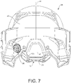
- Figs. 6 and 7 illustrate an example helmet 34 incorporating the helmet fit system 10.
- the harness 12 may be positioned within the helmet 34 having the anchors 28a, 28b secured to the helmet 34 over an inner surface 36 of the helmet 34.
- the anchors 28a, 28b may be positioned forward of the harness 12 and possibly above the anchors 28a 28b in use.
- the cable 24 is arranged as described above.
- the tensioning assembly 26 is positioned outside of the helmet and protrudes from, and may be secured to, an outer surface 40 of the helmet. Accordingly, the helmet may define a channel 38 between the inner surface 36 and the outer surface 40. One or more lengths of the cable 24 may pass through this channel 38 to span between the anchor 28b and the tensioning assembly 26. Where only one end portion of the cable 24 is taken up by the tensioning assembly 26, one end of the cable 24 may be fastened to an anchor on the inner surface 36 such that only one length of the cable 24 passes through the channel 38.
- the harness 12 extends below a lower rear edge 42 of the helmet 34 during use for at least some of the vertical positions of the harness 12.
- the attachment strip 14 may secure to the inner surface 36 of the helmet 34 and provide multiple attachment points for the harness 12.
- the tensioning assembly 26 is not centered laterally on the helmet 34 such that the tensioning assembly 26 may be easily accessed while the helmet 34 is worn.
- a plane of symmetry 44 of the helmet 34 bisecting left and right sides of the helmet.
- the plane of symmetry may be defined independent of non-symmetrical features on the helmet, e.g. the channel 38 or other features present on one side but not on the other.
- the tensioning assembly 26 may be offset from this plane of symmetry 44 by at least 15 percent, preferably at least 20 percent, and more preferably at least 25 percent, of the width of the helmet perpendicular to the line of symmetry 44.
Abstract
Description
- This application relates to helmets, and, more particularly, to adjustable fit systems for helmets.
- Although helmets may be made in various sizes, it is impractical to make a helmet for every head size. This is particularly the case for highly-specialized helmets, such as those used by fighter jet pilots. Accordingly, many helmets incorporate some form of fit adjustment. In modern helmets, this may take the form of an inner yoke or flexible frame with one or more parts that may be adjusted in length, such as with an adjustment wheel. Fit is important for comfort and for helmet stability, especially when used with helmet attachments such as various optics.
- It would be an advancement in the art to improve the functioning of an adjustable helmet.
- In one aspect of the invention, a helmet fit system may be mounted in a helmet and include: a harness; a first anchor; a second anchor; a tensioning mechanism; and a cable passing from a first point of securement on the tensioning mechanism, around the first anchor, through the harness, and around the second anchor. The tensioning mechanism is not secured to any portion of the harness. The harness may define a channel, the cable passing through the channel. The channel may be defined by a cover plate secured over a portion of the harness. The tensioning mechanism may be a dial tensioner. In some embodiments, the cable further passes from the second anchor, back through the harness, around the first anchor to a second point of securement on the tensioning mechanism. The harness may be adapted to conform to a head of a wearer of the helmet. The harness may define a plurality of webs defining one or more openings. In some embodiments, the helmet fit system includes a fastening strip defining a plurality of fastening points, the harness being configured to secure to any of the fastening points.
- In another aspect of the invention, a helmet is adapted to secure around a head of a wearer and has an inner surface and an outer surface, the helmet defining a plane of symmetry. A helmet fit system is mounted to the helmet, the helmet fit system including: a harness; a first anchor mounted to the inner surface of the helmet on a first side of the plane of symmetry; a second anchor mounted to the inner surface of the helmet on a second side of the plane of symmetry opposite the first side; a tensioning mechanism mounted to the outer surface of the helmet on the first side of the plane of symmetry; and a cable passing from a first point of securement on the tensioning mechanism, around the first anchor, through the harness, and around the second anchor. In some embodiments, the tensioning mechanism is a dial tensioner.
- In some embodiments, the helmet defines a channel defined between the inner surface and the outer surface and offset from the plane of symmetry, the cable passing from the first point of securement on the tensioning mechanism, through the channel, and around the first anchor.
- In some embodiments, the cable further passes from the second anchor, back through the harness, around the first anchor, through the channel, and to a second point of securement on the tensioning mechanism.
- In some embodiments, the tensioning mechanism is offset from the plane of symmetry by at least 15 percent of a width of the helmet perpendicular to the plane of symmetry. In some embodiments, the tensioning mechanism is offset from the plane of symmetry by at least 20 percent of a width of the helmet perpendicular to the plane of symmetry.
- In some embodiments, the harness defines a channel, the cable passing through the channel. The channel may be defined by a cover plate secured over a portion of the harness. The harness may be adapted to conform to a head of a wearer of the helmet. The harness may define a plurality of webs defining one or more openings. A fastening strip defining a plurality of fastening points may be secured to the inner surface of the helmet, the harness being configured to secure to any of the fastening points. The tensioning mechanism is not secured to harness by any structure other than the cable and the helmet.
- Preferred and alternative examples of the present invention are described in detail below with reference to the following drawings:
-
Fig. 1 is a rear isometric view of a helmet fit system in accordance with an embodiment of the present invention; -
Fig. 2 is a front isometric view of the helmet fit system in accordance with an embodiment of the present invention; -
Fig. 3 is a side view of the helmet fit system in accordance with an embodiment of the present invention; -
Fig. 4 is another side view of the helmet fit system in accordance with an embodiment of the present invention; -
Fig. 5 is another side view of the helmet fit system in accordance with an embodiment of the present invention; -
Fig. 6 is a view of the interior of a helmet incorporating the helmet fit system in accordance with an embodiment of the present invention; and -
Fig. 7 is a rear view of a helmet incorporating the helmet fit system in accordance with an embodiment of the present invention. - Referring to
Figs. 1 through 5 , ahelmet fit system 10 may include aharness 12. Theharness 12 may be a set of webs or straps that are intended to cradle the rear of a person's head when wearing a helmet. In the illustrated embodiment, theharness 12 includes anupper web 12a and alower web 12b defining an opening 12c between them. There may be any number of webs defining any number of openings in order to conform to the head of the wearer and to provide breathability. Theharness 12 may be made of semi-rigid plastic such that the harness is able to flex to conform to the head of a wearer but does not significantly stretch during use (e.g., stretches less than 2 percent in length during use relative to whenharness 12 is not being worn). For example, theharness 12 may be made of nylon, polyvinyl chloride (PVC), acrylonitrile butadiene styrene (ABS), or other polymer. - The
harness 12 may attach to a helmet at one or more points. In the illustrated embodiment, anattachment strip 14 secures to an inner rear surface of a helmet and defines a plurality ofattachment points 16 arranged vertically. Theharness 12 may include abarb 18 secured thereto, such as by co-molding. Thebarb 18 may be inserted into any of theattachment points 16 in order to attach theharness 12 to the helmet. Thebarb 18 may be removed in order to adjust the height of theharness 12 and may be configured such that the force required to remove is greater than the force required to insert within one of theattachment points 16. The vertical adjustability provided by thebarb 18 andattachment points 16 is just one example of an adjustable attachment approach and any approach known in the art for attaching aharness 12 to a helmet may be used. In some embodiments, theharness 12 is non-removably attached at one or more points to theharness 12, such as by rivets, welding, or other attachment means. - The
harness 12 may define achannel 20 extending across theharness 12 such that openings on either end of thechannel 20 are separated along a generally horizontal path (e.g., within 15 degrees of horizontal) when worn. Thechannel 20 may be defined by acover plate 22 secured to theharness 12, such as over thelower web 12b. Thechannel 20 may secure to thelower web 12b by means of welds, adhesive, rivets, or other fastening means. Thelower web 12b may define two or more ridges such that the channel is defined between the ridges. Alternatively, one or more grooves may be defined in thelower web 12b such thatchannel 20 is defined between thecover plate 22 and the grooves. - The
channel 20 defined between thecover plate 22 andlower web 12b may include a height and a width that are both at least twice a diameter of acable 24 passing through thechannel 20 along its entire length. As will be discussed below, two lengths of acable 24 may pass through thechannel 20 such that in at least one dimension, thechannel 20 is at least three times the diameter of thecable 24. Alternatively,multiple channels 20 may be defined between thecover plate 22 and thelower web 12b (e.g., multiple grooves in theweb 12b or three ridges extending between thecover plate 22 and thelower web 12b). In this case, eachchannel 20 may have a cross section that is greater than the diameter of thecable 24 in two orthogonal directions. - In some embodiments, end portions of the
cover plate 20 may be secured to theweb 12b by means of rivets orother fasteners channel 20 and provide a rounded region at the left and right entry points to facilitate sliding of thecable 24. - The
cable 24 may be tensioned by atensioning assembly 26. The tensioning assembly may provide a mechanism to take up thecable 24 or pay out thecable 24 on order to adjust the relative position of theharness 12. For example, the tensioningassembly 26 may be a BOA (Boa Technology, Inc.) tensioning system providing a ratcheting dial used to take up cable that may then be released to permit paying out of thecable 24. Any dial tensioning system known in the art may also be used. As is apparent inFigs 1 and2 , the tensioningassembly 26 is not secured to theharness 12. Instead, as discussed below, the tensioningassembly 26 secures to a helmet shell independently of theharness 12 such that movement and adjustment of theharness 12 does not change the position of thetensioning assembly 26 on the helmet. - The
cable 24 may further be routed aroundanchors harness 12. By adjusting the length of thecable 24, the position of theharness 12 relative to theanchors 28a. Theanchors channel 20 when the helmet is worn and the wearer's face is looking straight ahead. In this manner, the horizontal and vertical position of theharness 12 may be adjusted. - The
anchors rounded channel 30 that may be enclosed but for entry and exit points or may be open as a conventional pulley. Theanchors fastening points 32 in the form of openings sized to receive a rivet or other fastener. Alternatively, a fastener, e.g. a barbed rivet, may be integrally formed with eachanchor - A first end of the
cable 24 is secured within tensioningassembly 26. Thecable 24 passes aroundanchor 28a and into the left entry point of thechannel 20 in theharness 12. Thecable 24 passes through thechannel 20 and exits a right entry point of thechannel 20. Thecable 24 exits thechannel 20 and passes aroundanchor 28b. Thecable 24 passes fromanchor 28b back into the right entry point of thechannel 20. Thecable 24 passes through thechannel 20 and exits the left entry point of thechannel 20. Thecable 24 exits the left entry point of thechannel 20 and extends around theanchor 28a. Thecable 24 passes fromanchor 28a back into thetensioning assembly 26 where a second end of thecable 24 is fastened. - The tensioning
assembly 26 may apply tension to both ends of thecable 24. Bothend portions 24 of thecable 24 are taken up simultaneously. Alternatively, a first end of thecable 24 may be fixed to thetensioning assembly 26 or to an area of a helmet adjacent the tensioning assembly (e.g., within 1 cm) such that only an end portion including the second end is taken up by the tensioningassembly 26. -
Figs. 6 and7 illustrate anexample helmet 34 incorporating the helmetfit system 10. Theharness 12 may be positioned within thehelmet 34 having theanchors helmet 34 over aninner surface 36 of thehelmet 34. Theanchors harness 12 and possibly above theanchors 28acable 24 is arranged as described above. The tensioningassembly 26 is positioned outside of the helmet and protrudes from, and may be secured to, anouter surface 40 of the helmet. Accordingly, the helmet may define achannel 38 between theinner surface 36 and theouter surface 40. One or more lengths of thecable 24 may pass through thischannel 38 to span between theanchor 28b and thetensioning assembly 26. Where only one end portion of thecable 24 is taken up by the tensioningassembly 26, one end of thecable 24 may be fastened to an anchor on theinner surface 36 such that only one length of thecable 24 passes through thechannel 38. - In the illustrated embodiment, the
harness 12 extends below a lowerrear edge 42 of thehelmet 34 during use for at least some of the vertical positions of theharness 12. As noted above, theattachment strip 14 may secure to theinner surface 36 of thehelmet 34 and provide multiple attachment points for theharness 12. - As is apparent, the tensioning
assembly 26 is not centered laterally on thehelmet 34 such that thetensioning assembly 26 may be easily accessed while thehelmet 34 is worn. This contrasts to conventional approaches where a tensioning dial is mounted to theharness 12 and is not accessible while the helmet is worn, particularly where the wearer may be in a small cockpit or wearing gear that constrains movement. For example, considering a plane ofsymmetry 44 of thehelmet 34 bisecting left and right sides of the helmet. The plane of symmetry may be defined independent of non-symmetrical features on the helmet, e.g. thechannel 38 or other features present on one side but not on the other. The tensioningassembly 26 may be offset from this plane ofsymmetry 44 by at least 15 percent, preferably at least 20 percent, and more preferably at least 25 percent, of the width of the helmet perpendicular to the line ofsymmetry 44. - While the preferred embodiment of the invention has been illustrated and described, as noted above, many changes can be made without departing from the spirit and scope of the invention. In particular, a mirror configuration of the helmet
fit system 10 is possible, such as to accommodate both left handed and right handed wearers. Accordingly, the scope of the invention is not limited by the disclosure of the preferred embodiment. Instead, the invention should be determined entirely by reference to the claims that follow.
Claims (20)
- A helmet fit system for mounting in a helmet comprising:a harness;a first anchor;a second anchor;a tensioning mechanism; anda cable passing from a first point of securement on the tensioning mechanism, around the first anchor, through the harness, and around the second anchor;wherein the tensioning mechanism is not secured to any portion of the harness.
- The helmet fit system of claim 1, wherein the harness defines a channel, the cable passing through the channel.
- The helmet fit system of claim 2, wherein the channel is defined by a cover plate secured over a portion of the harness.
- The helmet fit system of claim 1, wherein the tensioning mechanism is a dial tensioner.
- The helmet fit system of claim 1, wherein the cable further passes from the second anchor, back through the harness, around the first anchor to a second point of securement on the tensioning mechanism.
- The helmet fit system of claim 1, wherein the harness is adapted to conform to a head of a wearer of the helmet.
- The helmet fit system of claim 1, wherein the harness defines a plurality of webs defining one or more openings.
- The helmet fit system of claim 1, further comprising a fastening strip defining a plurality of fastening points, the harness being configured to secure to any of the fastening points.
- A system comprising:a helmet adapted to secure around a head of a wearer and having an inner surface and an outer surface, the helmet defining a plane of symmetry; anda helmet fit system mounted to the helmet, the helmet fit system including:a harness;a first anchor mounted to the inner surface of the helmet on a first side of the plane of symmetry;a second anchor mounted to the inner surface of the helmet on a second side of the plane of symmetry opposite the first side;a tensioning mechanism mounted to the outer surface of the helmet on the first side of the plane of symmetry; anda cable passing from a first point of securement on the tensioning mechanism, around the first anchor, through the harness, and around the second anchor.
- The system of claim 1, wherein the helmet defines a channel defined between the inner surface and the outer surface and offset from the plane of symmetry, the cable passing from the first point of securement on the tensioning mechanism, through the channel, and around the first anchor.
- The system of claim 10, wherein the cable further passes from the second anchor, back through the harness, around the first anchor, through the channel, and to a second point of securement on the tensioning mechanism.
- The system of claim 9, wherein the tensioning mechanism is offset from the plane of symmetry by at least 15 percent of a width of the helmet perpendicular to the plane of symmetry.
- The system of claim 9, wherein the tensioning mechanism is offset from the plane of symmetry by at least 20 percent of a width of the helmet perpendicular to the plane of symmetry.
- The system of claim 9, wherein the harness defines a channel, the cable passing through the channel.
- The system of claim 14, wherein the channel is defined by a cover plate secured over a portion of the harness.
- The system of claim 9, wherein the tensioning mechanism is a dial tensioner.
- The helmet system of claim 9, wherein the harness is adapted to conform to a head of a wearer of the helmet.
- The system of claim 9, wherein the harness defines a plurality of webs defining one or more openings.
- The system of claim 1, further comprising a fastening strip defining a plurality of fastening points secured to the inner surface of the helmet, the harness being configured to secure to any of the fastening points.
- The system of claim 9, wherein the tensioning mechanism is not secured to harness by any structure other than the cable and the helmet.
Applications Claiming Priority (1)
| Application Number | Priority Date | Filing Date | Title |
|---|---|---|---|
| US17/115,149 US11583024B2 (en) | 2020-12-08 | 2020-12-08 | Helmet fit system |
Publications (2)
| Publication Number | Publication Date |
|---|---|
| EP4011231A2 true EP4011231A2 (en) | 2022-06-15 |
| EP4011231A3 EP4011231A3 (en) | 2022-09-07 |
Family
ID=78825162
Family Applications (1)
| Application Number | Title | Priority Date | Filing Date |
|---|---|---|---|
| EP21213115.5A Pending EP4011231A3 (en) | 2020-12-08 | 2021-12-08 | Helmet fit system |
Country Status (4)
| Country | Link |
|---|---|
| US (1) | US11583024B2 (en) |
| EP (1) | EP4011231A3 (en) |
| AU (1) | AU2021282432A1 (en) |
| GB (2) | GB2603282B (en) |
Families Citing this family (4)
| Publication number | Priority date | Publication date | Assignee | Title |
|---|---|---|---|---|
| US11700902B2 (en) * | 2020-01-08 | 2023-07-18 | ArmorSource, LLC | Helmet retention system |
| US11766084B2 (en) * | 2020-12-14 | 2023-09-26 | Zam Helmets Inc. | Adjustable chin cup |
| US20220378141A1 (en) * | 2021-05-28 | 2022-12-01 | Specialized Bicycle Components, Inc. | Bicycle helmet with modular impact absorbing structures |
| WO2024044724A1 (en) * | 2022-08-24 | 2024-02-29 | Resolution Strategic Development, Inc. | Helmet and adjustable chin strap and fit system assemblies |
Family Cites Families (23)
| Publication number | Priority date | Publication date | Assignee | Title |
|---|---|---|---|---|
| USRE32569E (en) | 1974-08-26 | 1988-01-05 | Gentex Corporation | Protective helmet |
| ATE197753T1 (en) | 1997-05-14 | 2000-12-15 | Heinz Egolf | HELMET WITH ADJUSTABLE STRAPS |
| US6865752B2 (en) * | 2002-12-23 | 2005-03-15 | Wilson Sporting Goods Co. | Adjustable sports helmet |
| US20050204456A1 (en) * | 2003-04-02 | 2005-09-22 | Dennis Piper | Retention system for headgear |
| FR2865356B1 (en) | 2004-01-28 | 2007-01-12 | Des Ouches Pascal Joubert | SEMI-RIGID PROTECTION HELMET |
| US8056150B2 (en) | 2007-05-08 | 2011-11-15 | Warrior Sports, Inc. | Helmet adjustment system |
| US8296868B2 (en) | 2007-08-17 | 2012-10-30 | Easton Sports, Inc. | Adjustable hockey helmet |
| FR2927777B1 (en) | 2008-02-27 | 2010-03-26 | Decathlon Sa | ADJUSTING DEVICE, IN PARTICULAR FOR A HELMET. |
| US8032993B2 (en) | 2009-01-08 | 2011-10-11 | Bell Sports, Inc. | Adjustment mechanism |
| EP2399472B1 (en) | 2010-06-28 | 2013-01-30 | Lazer Sport NV | A self-adjusting retention system for a helmet |
| US20130067643A1 (en) | 2011-09-16 | 2013-03-21 | Michael J. Musal | Adjustable sports helmet |
| US9179729B2 (en) | 2012-03-13 | 2015-11-10 | Boa Technology, Inc. | Tightening systems |
| CN202819762U (en) | 2012-07-25 | 2013-03-27 | 北京力达塑料制造有限公司 | Safety helmet with buffering function |
| WO2015065902A1 (en) | 2013-10-28 | 2015-05-07 | Intellectual Property Holdings, Llc | Helmet retention system |
| US10420385B2 (en) | 2014-04-25 | 2019-09-24 | Specialized Bicycle Components, Inc. | Bicycle helmet fit system |
| US20160165998A1 (en) * | 2014-12-10 | 2016-06-16 | Bell Sports, Inc. | Cord Lock Fit System for a Helmet |
| US20170006951A1 (en) | 2015-07-09 | 2017-01-12 | Boa Technology, Inc. | Fit systems for helmets |
| US10548363B2 (en) * | 2015-08-24 | 2020-02-04 | Bell Sports, Inc. | Helmet dampening fit system |
| WO2017091741A1 (en) | 2015-11-25 | 2017-06-01 | Bell Sports, Inc. | Helmet fit adjustment system with releasable hair aperture |
| WO2017111977A1 (en) * | 2015-12-24 | 2017-06-29 | Maloney Brad W | Helmet harness |
| CN105876964A (en) | 2016-06-23 | 2016-08-24 | 佛山市联智新创科技有限公司 | Safety helmet with multiple adjusting ways |
| US11357279B2 (en) * | 2017-05-09 | 2022-06-14 | Boa Technology Inc. | Closure components for a helmet layer and methods for installing same |
| BE1025854B1 (en) | 2018-05-09 | 2019-07-23 | Forhed Sprl | PROTECTIVE HELMET HAVING A MECHANICAL SIZE ADJUSTMENT SYSTEM |
-
2020
- 2020-12-08 US US17/115,149 patent/US11583024B2/en active Active
-
2021
- 2021-12-08 GB GB2117704.3A patent/GB2603282B/en active Active
- 2021-12-08 AU AU2021282432A patent/AU2021282432A1/en active Pending
- 2021-12-08 EP EP21213115.5A patent/EP4011231A3/en active Pending
- 2021-12-08 GB GB2305824.1A patent/GB2618912B/en active Active
Also Published As
| Publication number | Publication date |
|---|---|
| US20220175074A1 (en) | 2022-06-09 |
| GB202117704D0 (en) | 2022-01-19 |
| GB2603282B (en) | 2023-05-31 |
| GB2603282A (en) | 2022-08-03 |
| GB2618912A (en) | 2023-11-22 |
| GB202305824D0 (en) | 2023-06-07 |
| EP4011231A3 (en) | 2022-09-07 |
| GB2618912B (en) | 2024-03-13 |
| AU2021282432A1 (en) | 2022-06-23 |
| US11583024B2 (en) | 2023-02-21 |
Similar Documents
| Publication | Publication Date | Title |
|---|---|---|
| EP4011231A2 (en) | Helmet fit system | |
| US10918167B2 (en) | Friction stop strap adjustor | |
| US6952841B2 (en) | Sports goggles | |
| US11357279B2 (en) | Closure components for a helmet layer and methods for installing same | |
| US6081932A (en) | Chin strap assembly for use with an athletic helmet | |
| JPH0613216Y2 (en) | Helmet | |
| EP2937005B1 (en) | Bicycle helmet fit system | |
| US8353066B2 (en) | Easily adjusted retention system for helmets | |
| US11391546B2 (en) | Ballistic helmet with an accessory system | |
| JP6042105B2 (en) | strap | |
| EP2222197B1 (en) | Head and neck support device | |
| US9433259B2 (en) | Self-actuating webbing adjuster and helmet strap system including same | |
| SK50993A3 (en) | Protective headgear and detachable face protector | |
| US20050210567A1 (en) | Retention system for safety helmet | |
| US20170006951A1 (en) | Fit systems for helmets | |
| US5335371A (en) | Baseball infielder's mask | |
| EP1048535B1 (en) | Shoulder belt adjuster for safety belt system | |
| US20130326798A1 (en) | Protective headgear for combat sports | |
| JP6042419B2 (en) | strap | |
| US20190343215A1 (en) | Protective bicycle helmet with internal ventilation fit system comprising expanded connectors | |
| US20170128253A1 (en) | Devices and methods for supporting the head and neck | |
| CA3091631A1 (en) | Adjustable face mask | |
| US20230086118A1 (en) | Protective bicycle helmet with internal ventilation fit system comprising expanded connectors |
Legal Events
| Date | Code | Title | Description |
|---|---|---|---|
| PUAI | Public reference made under article 153(3) epc to a published international application that has entered the european phase |
Free format text: ORIGINAL CODE: 0009012 |
|
| STAA | Information on the status of an ep patent application or granted ep patent |
Free format text: STATUS: THE APPLICATION HAS BEEN PUBLISHED |
|
| AK | Designated contracting states |
Kind code of ref document: A2 Designated state(s): AL AT BE BG CH CY CZ DE DK EE ES FI FR GB GR HR HU IE IS IT LI LT LU LV MC MK MT NL NO PL PT RO RS SE SI SK SM TR |
|
| PUAL | Search report despatched |
Free format text: ORIGINAL CODE: 0009013 |
|
| AK | Designated contracting states |
Kind code of ref document: A3 Designated state(s): AL AT BE BG CH CY CZ DE DK EE ES FI FR GB GR HR HU IE IS IT LI LT LU LV MC MK MT NL NO PL PT RO RS SE SI SK SM TR |
|
| RIC1 | Information provided on ipc code assigned before grant |
Ipc: A42B 3/14 20060101AFI20220803BHEP |
|
| STAA | Information on the status of an ep patent application or granted ep patent |
Free format text: STATUS: REQUEST FOR EXAMINATION WAS MADE |
|
| 17P | Request for examination filed |
Effective date: 20221018 |
|
| RBV | Designated contracting states (corrected) |
Designated state(s): AL AT BE BG CH CY CZ DE DK EE ES FI FR GB GR HR HU IE IS IT LI LT LU LV MC MK MT NL NO PL PT RO RS SE SI SK SM TR |
|
| GRAP | Despatch of communication of intention to grant a patent |
Free format text: ORIGINAL CODE: EPIDOSNIGR1 |
|
| STAA | Information on the status of an ep patent application or granted ep patent |
Free format text: STATUS: GRANT OF PATENT IS INTENDED |
|
| INTG | Intention to grant announced |
Effective date: 20240122 |