EP4011188A1 - Lawn mower and cutting blade - Google Patents
Lawn mower and cutting blade Download PDFInfo
- Publication number
- EP4011188A1 EP4011188A1 EP21210918.5A EP21210918A EP4011188A1 EP 4011188 A1 EP4011188 A1 EP 4011188A1 EP 21210918 A EP21210918 A EP 21210918A EP 4011188 A1 EP4011188 A1 EP 4011188A1
- Authority
- EP
- European Patent Office
- Prior art keywords
- axis
- cutting blade
- section
- cross
- main body
- Prior art date
- Legal status (The legal status is an assumption and is not a legal conclusion. Google has not performed a legal analysis and makes no representation as to the accuracy of the status listed.)
- Granted
Links
Images





Classifications
-
- A—HUMAN NECESSITIES
- A01—AGRICULTURE; FORESTRY; ANIMAL HUSBANDRY; HUNTING; TRAPPING; FISHING
- A01D—HARVESTING; MOWING
- A01D34/00—Mowers; Mowing apparatus of harvesters
- A01D34/01—Mowers; Mowing apparatus of harvesters characterised by features relating to the type of cutting apparatus
- A01D34/412—Mowers; Mowing apparatus of harvesters characterised by features relating to the type of cutting apparatus having rotating cutters
- A01D34/63—Mowers; Mowing apparatus of harvesters characterised by features relating to the type of cutting apparatus having rotating cutters having cutters rotating about a vertical axis
- A01D34/73—Cutting apparatus
-
- A—HUMAN NECESSITIES
- A01—AGRICULTURE; FORESTRY; ANIMAL HUSBANDRY; HUNTING; TRAPPING; FISHING
- A01D—HARVESTING; MOWING
- A01D34/00—Mowers; Mowing apparatus of harvesters
- A01D34/01—Mowers; Mowing apparatus of harvesters characterised by features relating to the type of cutting apparatus
- A01D34/412—Mowers; Mowing apparatus of harvesters characterised by features relating to the type of cutting apparatus having rotating cutters
- A01D34/63—Mowers; Mowing apparatus of harvesters characterised by features relating to the type of cutting apparatus having rotating cutters having cutters rotating about a vertical axis
- A01D34/67—Mowers; Mowing apparatus of harvesters characterised by features relating to the type of cutting apparatus having rotating cutters having cutters rotating about a vertical axis hand-guided by a walking operator
- A01D34/68—Mowers; Mowing apparatus of harvesters characterised by features relating to the type of cutting apparatus having rotating cutters having cutters rotating about a vertical axis hand-guided by a walking operator with motor driven cutters or wheels
- A01D34/69—Mowers; Mowing apparatus of harvesters characterised by features relating to the type of cutting apparatus having rotating cutters having cutters rotating about a vertical axis hand-guided by a walking operator with motor driven cutters or wheels with motor driven wheels
-
- A—HUMAN NECESSITIES
- A01—AGRICULTURE; FORESTRY; ANIMAL HUSBANDRY; HUNTING; TRAPPING; FISHING
- A01D—HARVESTING; MOWING
- A01D2101/00—Lawn-mowers
Definitions
- the present disclosure relates to a power tool and, in particular, to a lawn mower and a cutting blade.
- a lawn mower cuts vegetation through a cutting blade.
- An ineffective load of the blade is an important factor affecting the time of endurance and mowing performance of the lawn mower.
- due to the design requirements for the strength of the blade it is often difficult to reduce the ineffective load of the blade, which is not conducive to the optimization of the overall performance of the lawn mower.
- a cutting blade is capable of being mounted to a lawn mower.
- the cutting blade is capable of being driven to rotate around a first axis.
- the cutting blade includes cutting portions including cutting edges for cutting and extension portions closer to the first axis relative to the cutting portions.
- Each of the extension portions includes a main body, and the main body constitutes a main part of each of the extension portions.
- Each of the extension portions is configured to have at least three planes passing through the first axis, and cross-sections of the main body on the at least three planes are substantially the same.
- the main body includes a first section and a second section disposed on two sides of a centerline of the main body, and a vertical distance between each point, on an inner edge of a cross-section perpendicular to the first axis, of at least part of the first section and the first axis is the same.
- the main body includes an upper surface and a lower surface, and the upper surface is a part of the side surface of a first cone with the first axis as an axis.
- the lower surface is a part of the side surface of a second cone with the first axis as an axis.
- the main body includes a centerline, and a distance between the upper surface and the lower surface is the same along any direction parallel to the centerline.
- the main body includes a first cross-section in a plane perpendicular to the first axis, and the inner and outer edges of the first cross-section are parallel arcs.
- the main body includes a first cross-section in a plane perpendicular to the first axis, the main body has an equivalent load region corresponding to the cross-section when the cutting blade is driven to rotate, and a ratio of an area of the first cross-section to an area of the equivalent load region is configured to be greater than or equal to 75%.
- the first cross-section substantially coincides with the equivalent load region.
- the main body includes a light-loaded section, a ratio of an area of any cross-section of the light-loaded section in a plane perpendicular to the first axis to an area of an equivalent load region of the any cross-section is configured to be greater than or equal to 75%, and a ratio of a length of the main body in a direction of a centerline of the main body to a length of the light-loaded section in the direction of the centerline of the main body is greater than or equal to 1 and less than or equal to 3.
- any cross-section of the light-loaded section in a plane perpendicular to the first axis coincides with an equivalent load region corresponding to the any cross-section.
- a cutting blade is capable of being driven to rotate around a first axis.
- the cutting blade includes cutting portions including cutting edges for cutting and extension portions closer to the first axis relative to the cutting portions.
- Each of the extension portions includes an upper surface and a lower surface, at least part of the upper surface is a part of the side surface of a first cone with the first axis as an axis, or at least part of the lower surface is a part of the side surface of a second cone with the first axis as an axis.
- each of the extension portions includes a main body, the main body constitutes a main part of the each of the extension portions and includes a first section and a second section disposed on two sides of a centerline of the main body, and a vertical distance between each point, on an inner edge of a cross-section perpendicular to the first axis, of at least part of the first section and the first axis is the same.
- a vertical distance between each point, on an edge of a cross-section perpendicular to the first axis, of at least part of the second section and the first axis is the same.
- the upper surface is a part of the side surface of the first cone with the first axis as the axis.
- the lower surface is a part of the side surface of the second cone with the first axis as the axis.
- each of the extension portions includes a main body and a rib
- the main body constitutes a main part of the each of the extension portions
- the rib is disposed on the main body.
- the main body includes a centerline, and a distance between the upper surface and the lower surface is the same along any direction parallel to the centerline.
- the main body includes a first cross-section in a plane perpendicular to the first axis, and the inner and outer edges of the first cross-section are parallel arcs.
- At least part of the upper surface is a part of the side surface of the first cone with the first axis as an axis
- at least part of the lower surface is a part of the side surface of the second cone with the first axis as an axis.
- a lawn mower in one example of the disclosure, includes a cutting blade, a base connected to the cutting blade, a motor configured to drive the cutting blade to rotate around a first axis and driving wheels configured to drive the base to move.
- the cutting blade includes cutting portions for cutting and extension portions closer to the first axis relative to the cutting portions, each of the extension portions includes an upper surface and a lower surface, at least part of the upper surface is a part of the side surface of a first cone with the first axis as an axis, or at least part of the lower surface is a part of the side surface of a second cone with the first axis as an axis.
- the present disclosure provides a cutting blade 100 and a lawn mower 200 using the cutting blade 100.
- the cutting blade 100 can be driven by the lawn mower 200 to rotate around a first axis 102.
- the lawn mower 200 implements a mowing operation through the cutting blade 100.
- the lawn mower 200 includes a base 210, a motor 230, a power supply, and driving wheels 220.
- the cutting blade 100 is connected to the base 210.
- the motor 230 is disposed in the base 210.
- the blade and the base 210 are connected through the motor.
- the motor 230 is configured to drive the cutting blade 100 to rotate.
- the cutting blade 100 is generally disposed in a chassis below the base 210 and cuts vegetation by rotating.
- the power supply is connected to the base 210 and configured to supply power to the motor 230.
- the driving wheels 220 are connected to the base 210 to achieve the movement of the lawn mower 200.
- a user may supply power to drive the driving wheels 220 to move, or the motor 230 may be provided to supply power to the driving wheels 220 so that the driving wheels 220 is self-propelled.
- the cutting blade 100 includes a central portion 110, cutting portions 120, and extension portions 130, where the central portion 110 is configured to be connected to the motor 230 of the lawn mower 200.
- the lawn mower 200 includes an output shaft connected to the motor 230, and the cutting blade 100 is detachably connected to the output shaft.
- the output shaft extends from an inside of the base 210 to a lower side of the base 210 to drive the cutting blade 100 to rotate.
- the central portion 110 is connected to the output shaft, and a cutting blade is driven to rotate through the output shaft when the motor 230 is operating.
- a rotation center 101 of the cutting blade 100 is disposed on the central portion 110, and the cutting blade 100 can rotate around the first axis 102 passing through the rotation center 101.
- the output shaft is connected to the cutting blade 100 at the rotation center 101 of the cutting blade 100, and the motor 230 and the output shaft extend along the first axis 102 to drive the cutting blade 100 to rotate around the first axis 102.
- the cutting blade 100 is symmetrical about the rotation center 101, and the cutting portions 120 are disposed on two sides of the rotation center 101.
- the extension portion 130 includes a main body 131 and a rib 132.
- the extension portion 130 includes a centerline 103 passing through a center of a main body 131.
- the main body 131 is basically symmetrical about the centerline 103.
- the centerline 103 is located substantially in a middle of the main body 131. Referring to FIG. 3 , a projection of the extension portion 130 along an axial direction of the first axis 102 extends along the centerline 103.
- the centerline 103 is perpendicular to the first axis 102.
- an extending direction of the cutting portion 120 is a radial direction of the first axis 102.
- the cutting portions 120 include cutting edges 121 for cutting.
- the extension portion 130 is connected to the cutting portion 120 and the central portion 110.
- the extension portions 130 are disposed on two sides of the rotation center 101.
- the extension portions are closer to the first axis 102 relative to the cutting portions 120 and extend along the centerline 103 to two sides of the rotation center 101.
- the extension portion 130 is disposed between the central portion 110 and the cutting portion 120.
- the extension portions 130 extend downward so that in the axial direction of the first axis 102, a height of the cutting portion 120 is lower than a height of the central portion 110. In this manner, the cutting portions 120 can cut vegetation at low places and the collision of obstacles such as the ground on the central portion 110 can be reduced.
- the rib 132 is disposed on the main body 131 and configured to strengthen the strength of the main body 131.
- the main body 131 constitutes a main part of the extension portion 130.
- the main body 131 referred to in the present disclosure should be regarded as a structure where the rib 132 is removed. For example, a convex part of the rib 132 is removed, and a recess generated by the rib 132 is filled so that a surface of the main body is smooth.
- An additional structure such as a convex on a surface of the extension portion 130 is not a part of the main body 131.
- the cutting edge is disposed at a side end of the extension portion and configured to cut vegetation.
- an operation load of the cutting blade 100 is mainly composed of a cutting load generated by cutting vegetation and a blade load generated by the blade when the blade rotates. Therefore, reducing the blade load can effectively improve the endurance of the lawn mower 200 and improve the actual cutting load capacity of the blade.
- the main body 131 has an equivalent load region 1312 on any first cross-section 1311 in a plane perpendicular to of the first axis 102.
- a ratio of an area of the first cross-section 1311 to an area of the equivalent load region 1312 of the first cross-section 1311 is configured to be greater than or equal to 75%.
- the ratio of the area of the first cross-section 1311 to the area of the equivalent load region 1312 of the first cross-section 1311 is configured to be greater than or equal to 85%.
- the first cross-section 1311 of the main body 131 refers to a figure in which the cross-section of the extension portion 130 in the plane removes the cross-section of the rib 132 and fills the recess corresponding to the rib 132.
- a point of the first cross-section 1311 that is farthest from the rotation center 101 is a farthest point P1
- a circle centered on a point on the rotation center 101 and passing through the farthest point P1 is the first equivalent load circle.
- a point of the first cross section 1311 that is nearest from the rotation center 101 is the nearest point P2, and a circle centered on the point on the rotation center 101 and passing through the nearest point P2 is the second equivalent load circle.
- a ring between the first equivalent load circle and the second equivalent load circle is an equivalent load ring 105.
- a section on the equivalent load ring 105 passing through the outermost edge of the first cross-section 1311 is the equivalent load region 1312 of the first cross-section 1311.
- the area of the equivalent load region 1312 of the first cross-section 1311 affects the load of the first-section 1311 of the cutting blade 100 when the cutting blade 100 is operating, that is, the larger the area of the equivalent load region 1312 is, the larger the blade load generated when the cutting blade 100 rotates is.
- the blade load may be understood as a load generated by driving the cutting blade 100 when the lawn mower 200 is unloaded.
- the extension portion 130 in a direction along a radial direction of the centerline 103 and farther from the centerline 103, the extension portion 130 has a downward trend (in the figure, a direction perpendicular to a plane where the figure is located and extending to a rear of the plane is a downward direction).
- the downward direction refers to a position of the driving wheel relative to the base, and a cutting portion is located relatively below the central portion.
- FIGS. 8A, 8B , and 8C at least three planes 106 passing through the first axis 102 exist, and cross-sections of the main body 131 on the planes 106 are basically the same.
- the cross-sections are the same, which means that shapes and dimensions of the cross-sections are the same; the cross-sections are basically the same, which means that extending shapes of the cross-sections are basically the same, and a difference between areas of the cross-sections is less than 10% of the area.
- the difference between the cross-sections caused by the deformation of the rib or the surface of the blade belongs to the case where the cross-sections are basically the same.
- the case where the cross-sections crossed by two planes with a small included angle are basically the same does not belong to the "basically the same" as provided in the present disclosure.
- the planes 106 pass through the first axis 102, which means that the first axis 102 is located in the planes 106 and is a line of intersection of the three planes 106.
- the main body 131 provided in the present disclosure should be understood as the main part of the extension portion 130.
- the deformation of the surface of the extension portion 130, or the addition or deletion of other structures should not be regarded as the main body of the extension portion provided in the present disclosure.
- extension portion 130 and the cutting portion 120 have a connecting line 108, the extension portion 130 and the cutting portion 120 are connected at the connecting line 108, and a cross-section of the main body on any plane passing through the first axis 102 and cutting the connecting line 108 is the same.
- the main body 131 includes a first section 133 and a second section 134 disposed on two sides of the rib 132.
- the rib 132 passes through the centerline 103, and the first section 133 and the second section 134 are symmetrical about the centerline 103.
- a vertical distance L1 between each point, on an inner edge 1313 of the first cross-section 1311 perpendicular to the first axis 102, of at least part of the first section 133 and the first axis 102 is the same.
- a vertical distance L1 between each point, on an edge of the first cross-section 1311 perpendicular to the first axis 102, of at least part of the second section 134 and the first axis 102 is the same.
- the inner edge 1313 of the first cross-section 1311 refers to an edge line of the first section 133 closer to the rotation center 101, and the first cross-section 1311 should further include an outer edge line farther from the rotation center 101, where a vertical distance between each point on the outer edge line and the first axis 102 is also equal.
- the vertical distance between each point on the inner edge 1313 of the first cross-section 1311 and the first axis 102 refers to a length of a vertical line of each point on the inner edge 1313 of the first cross-section 1311 to the first axis.
- the structure of the main body 131 is adapted to the rotational movement of the cutting blade so that the edge of the first cross-section 1311 of the main body 131 is consistent with an overall circular trajectory of the first cross-section 1311 when the lawn mower 200 rotates. In this manner, the space of the equivalent load region 1312 corresponding to the first cross-section 1311 is fully used so that while the overall strength of the cutting blade 100 is not reduced, the blade load of the cutting blade 100 is reduced.
- a cutting surface formed by the first cross-section 1311, perpendicular to the first axis 102, of at least part of the first section 133 when the cutting blade 100 rotates around the first axis 102 is a surface of revolution with the first axis 102 as a rotation axis so that the cutting surface formed by the first cross-section 1311, perpendicular to the first axis 102, of the first section 133 when the cutting blade 100 rotates around the first axis 102 is a ring surface.
- the main body 131 includes an upper surface 135 and a lower surface 136.
- the upper surface 135 is a part of the side surface of a first cone 104 with the first axis 102 as an axis
- the lower surface 136 is a part of the side surface of a second cone 105 with the first axis 102 as an axis. Therefore, edges of the first cross-section 1311 of the first section 133 in the radial direction of the first axis 102 should be a line segment on the upper surface 135 and a line segment on the lower surface 136, respectively.
- the edge of the first cross-section 1311 is an arc on a circle with a certain point on the first axis 102 as a center.
- edges of the first cross-section 1311 of the second section 134 in the radial direction of the first axis 102 should be a line segment on the upper surface 135 and a line segment on the lower surface 136, respectively.
- the edge of the first cross-section 1311 is an arc on a circle with a certain point on the first axis 102 as a center.
- a distance between the upper surface 135 and the lower surface 136 is the same, and the inner and outer edges (1311c, 1311d) of the first cross-section 1311 are parallel arcs, which improves the balance of the cutting blade.
- the main body 131 is configured to have at least one first cross-section 1311 in the radial direction of the first axis 102, and the first cross-section 1311 coincides with the equivalent load region 1312 so that the blade load of the cutting blade 100 can be reduced.
- the main body 131 is configured to have at least one region; in this region, any first cross-section 1311 in the radial direction of the first axis 102 coincides with the corresponding equivalent load region 1312, thereby improving the performance of the lawn mower 200.
- the cutting blade 100 is configured such that any first cross-section 1311 of the extension portion 130 of the cutting blade 100 in the radial direction of the first axis 102 coincides with the corresponding equivalent load region 1312.
- the cutting blade 100 provided in the present disclosure is a first cutting blade
- the existing cutting blade is a second cutting blade 100a.
- a first cross-section 1311a of the second extension portion is generally rectangular or irregular (not considering a structure of a rib).
- the first cross-section 1311a is a rectangle.
- An equivalent load region 1312a corresponding to the first cross-section 1311a is an arc passing through four points on an outermost edge of the first cross-section 1311a, that is, in the second cutting blade 100a, an area of the first cross-section 1311a is less than an area of the corresponding equivalent load region 1312a.
- the blade since the blade is generally designed symmetrically about the centerline, cross-sections of the main body on at most two planes, passing through the first axis, of the blade are the same. Referring to FIGS. 14 and 15 , an area of an equivalent load ring 105a when the second cutting blade is operating is greater than an area of the equivalent load ring 105 when the first cutting blade is operating.
- a blade load of the second cutting blade 100a in operation is greater than the blade load of the first cutting blade in operation.
- the first cutting blade provided in the present disclosure can reduce the blade load by 5% to 20% compared to the traditional second cutting blade, thereby improving the time of endurance of the lawn mower and improving the mowing performance of the lawn mower.
- the main body 131 extends along the centerline 103 to two sides of the rotation center 101. Referring to FIG. 16 , the main body 131 includes a light-loaded section 137. A ratio of an area of any first cross-section 1311 of the light-loaded section 137 in the radial direction of the first axis 102 to an area of the equivalent load region 1312 of the first cross-section 1311 is configured to be greater than or equal to 75%. Optionally, the ratio of the area of the first cross-section 1311 to the area of the equivalent load region 1312 of the first cross-section 1311 is configured to be greater than or equal to 85%.
- a ratio of a length of the main body 131 in a direction of the centerline 103 to a length of the light-loaded section 137 in the direction of the centerline 103 is greater than or equal to 1 and less than or equal to 3, so as to improve the endurance of the lawn mower 200 and improve the cutting performance of the lawn mower 200.
- any first cross-section 1311 of the light-loaded section 137 in the radial direction of the first axis 102 coincides with the equivalent load region 1312 corresponding to the first cross-section 1311.
- the cutting portion 120 has the equivalent load region 1312 on any first cross-section 1311 in the radial direction of the first axis 102, the cutting portion 120 is configured to have at least one cross-section in the radial direction of the first axis 102, and a ratio of an area of the cross-section to an area of the equivalent load region of the section is configured to be greater than or equal to 75%.
- the light-loaded section is configured to be a section on the cutting blade, which may be a section in an extending direction of the centerline; along the extending direction of the centerline, the extension portion has a part that is not the light-loaded section.
- the light-loaded section is configured to be a section on the cutting blade, which may be a section in the radial direction of the centerline; in the radial direction of the centerline, the extension portion has the light-loaded section and a non-light-loaded section.
- At least part of the upper surface of the main body is a part of the side surface of a first cone with the first axis as the axis
- at least part of the lower surface of the main body is a part of the side surface of a second cone with the first axis as the axis.
- an extension portion 130b only includes a main body 131b without a rib, and the structure of the main body 131b is also adapted to the description in the preceding embodiments.
- the extension portion further includes a rib, and cross-sections of the rib on at least three planes passing through the first axis are the same, that is, the structure of the rib is made similar to the structure of the main body, so as to reduce the blade load generated by the rib when the blade rotates.
Landscapes
- Life Sciences & Earth Sciences (AREA)
- Environmental Sciences (AREA)
- Harvester Elements (AREA)
Abstract
Description
- The present disclosure relates to a power tool and, in particular, to a lawn mower and a cutting blade.
- A lawn mower cuts vegetation through a cutting blade. An ineffective load of the blade is an important factor affecting the time of endurance and mowing performance of the lawn mower. However, due to the design requirements for the strength of the blade, it is often difficult to reduce the ineffective load of the blade, which is not conducive to the optimization of the overall performance of the lawn mower.
- In one example of the disclosure, a cutting blade is capable of being mounted to a lawn mower. When the cutting blade is mounted to the lawn mower, the cutting blade is capable of being driven to rotate around a first axis. The cutting blade includes cutting portions including cutting edges for cutting and extension portions closer to the first axis relative to the cutting portions. Each of the extension portions includes a main body, and the main body constitutes a main part of each of the extension portions. Each of the extension portions is configured to have at least three planes passing through the first axis, and cross-sections of the main body on the at least three planes are substantially the same.
- In one example, the main body includes a first section and a second section disposed on two sides of a centerline of the main body, and a vertical distance between each point, on an inner edge of a cross-section perpendicular to the first axis, of at least part of the first section and the first axis is the same.
- In one example, the main body includes an upper surface and a lower surface, and the upper surface is a part of the side surface of a first cone with the first axis as an axis.
- In one example, the lower surface is a part of the side surface of a second cone with the first axis as an axis.
- In one example, the main body includes a centerline, and a distance between the upper surface and the lower surface is the same along any direction parallel to the centerline.
- In one example, the main body includes a first cross-section in a plane perpendicular to the first axis, and the inner and outer edges of the first cross-section are parallel arcs.
- In one example, the main body includes a first cross-section in a plane perpendicular to the first axis, the main body has an equivalent load region corresponding to the cross-section when the cutting blade is driven to rotate, and a ratio of an area of the first cross-section to an area of the equivalent load region is configured to be greater than or equal to 75%.
- In one example, the first cross-section substantially coincides with the equivalent load region.
- In one example, the main body includes a light-loaded section, a ratio of an area of any cross-section of the light-loaded section in a plane perpendicular to the first axis to an area of an equivalent load region of the any cross-section is configured to be greater than or equal to 75%, and a ratio of a length of the main body in a direction of a centerline of the main body to a length of the light-loaded section in the direction of the centerline of the main body is greater than or equal to 1 and less than or equal to 3.
- In one example, any cross-section of the light-loaded section in a plane perpendicular to the first axis coincides with an equivalent load region corresponding to the any cross-section.
- In one example of the disclosure, a cutting blade is capable of being driven to rotate around a first axis. The cutting blade includes cutting portions including cutting edges for cutting and extension portions closer to the first axis relative to the cutting portions. Each of the extension portions includes an upper surface and a lower surface, at least part of the upper surface is a part of the side surface of a first cone with the first axis as an axis, or at least part of the lower surface is a part of the side surface of a second cone with the first axis as an axis.
- In one example, each of the extension portions includes a main body, the main body constitutes a main part of the each of the extension portions and includes a first section and a second section disposed on two sides of a centerline of the main body, and a vertical distance between each point, on an inner edge of a cross-section perpendicular to the first axis, of at least part of the first section and the first axis is the same.
- In one example, a vertical distance between each point, on an edge of a cross-section perpendicular to the first axis, of at least part of the second section and the first axis is the same.
- In one example, the upper surface is a part of the side surface of the first cone with the first axis as the axis.
- In one example, the lower surface is a part of the side surface of the second cone with the first axis as the axis.
- In one example, each of the extension portions includes a main body and a rib, the main body constitutes a main part of the each of the extension portions, and the rib is disposed on the main body.
- In one example, the main body includes a centerline, and a distance between the upper surface and the lower surface is the same along any direction parallel to the centerline.
- In one example, the main body includes a first cross-section in a plane perpendicular to the first axis, and the inner and outer edges of the first cross-section are parallel arcs.
- In one example, at least part of the upper surface is a part of the side surface of the first cone with the first axis as an axis, and at least part of the lower surface is a part of the side surface of the second cone with the first axis as an axis.
- In one example of the disclosure, a lawn mower includes a cutting blade, a base connected to the cutting blade, a motor configured to drive the cutting blade to rotate around a first axis and driving wheels configured to drive the base to move. The cutting blade includes cutting portions for cutting and extension portions closer to the first axis relative to the cutting portions, each of the extension portions includes an upper surface and a lower surface, at least part of the upper surface is a part of the side surface of a first cone with the first axis as an axis, or at least part of the lower surface is a part of the side surface of a second cone with the first axis as an axis.
-
-
FIG. 1 is a structural view of a lawn mower according to an embodiment of the present disclosure; -
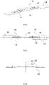
FIG. 2 is a perspective view of a cutting blade according to an embodiment of the present disclosure; -
FIG. 3 is a plan view of the cutting blade inFIG. 2 of the present disclosure; -
FIG. 4 is a plan view of the cutting blade inFIG. 2 of the present disclosure from another angle; -
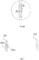
FIG. 5 is a sectional view of an extension portion of the cutting blade inFIG. 2 of the present disclosure; -
FIG. 6A is a is the equivalent load ring of the main body corresponding to a first section; -
FIG. 6B is an enlarged view of a partial area ofFIG. 6A ; -
FIG. 7 is a schematic view of a cross-section of the extension portion inFIG. 5 of the present disclosure and an equivalent load region of the cross-section; -
FIGS. 8A and 8B are schematic views of planes passing through a first axis according to an embodiment of the present disclosure; -
FIG. 8C is a sectional view of an extension portion in the plane inFIG. 8A of present disclosure; -
FIGS. 9A and 9B are schematic views illustrating a vertical distance between a point on an edge of a cross-section of the extension portion inFIG. 5 and a first axis according to the present disclosure; -
FIG. 10 is a schematic view of a first cone and a second cone in the cutting blade inFIG. 2 of the present disclosure; -
FIG. 11 is a structural view of an existing second cutting blade; -
FIG. 12 is a sectional circular view of a cross-section of a second extension portion of the second cutting blade inFIG. 11 of the present disclosure; -
FIG. 13 is a comparison view of equivalent load regions of a first cutting blade and a second cutting blade; -
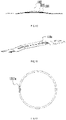
FIG. 14 is a schematic view of an equivalent load ring when a cross-section of the cutting blade inFIG. 5 rotates; -
FIG. 15 is a schematic view of an equivalent load ring when a cross-section of a second cutting blade rotates; -
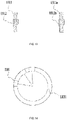
FIG. 16 is a structural view of a light-loaded section of a cutting blade according to an embodiment of the present disclosure; -
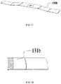
FIG. 17 is a structural view of a cutting blade according to an embodiment of the present disclosure; and -
FIG. 18 is a sectional view of the cutting blade inFIG. 17 . - Embodiments in accordance with the present disclosure are described in detail hereinafter. Examples of the embodiments are illustrated in the drawings, where the same or similar reference numerals indicate the same or similar elements or elements having the same or similar functions. The embodiments described hereinafter with reference to the drawings are merely exemplary. The embodiments are intended to explain the present disclosure and are not to be construed as limiting the present disclosure.
- Technical solutions of the present disclosure are further described hereinafter in conjunction with drawings and embodiments.
- Referring to
FIGS. 1 and2 , the present disclosure provides acutting blade 100 and alawn mower 200 using thecutting blade 100. When thecutting blade 100 is mounted to thelawn mower 200, thecutting blade 100 can be driven by thelawn mower 200 to rotate around afirst axis 102. Thelawn mower 200 implements a mowing operation through thecutting blade 100. Thelawn mower 200 includes abase 210, amotor 230, a power supply, and drivingwheels 220. Thecutting blade 100 is connected to thebase 210. Themotor 230 is disposed in thebase 210. The blade and the base 210 are connected through the motor. Themotor 230 is configured to drive thecutting blade 100 to rotate. Thecutting blade 100 is generally disposed in a chassis below thebase 210 and cuts vegetation by rotating. The power supply is connected to thebase 210 and configured to supply power to themotor 230. The drivingwheels 220 are connected to the base 210 to achieve the movement of thelawn mower 200. Optionally, a user may supply power to drive the drivingwheels 220 to move, or themotor 230 may be provided to supply power to the drivingwheels 220 so that the drivingwheels 220 is self-propelled. - Referring to
FIGS. 3 and 4 , thecutting blade 100 includes acentral portion 110, cuttingportions 120, andextension portions 130, where thecentral portion 110 is configured to be connected to themotor 230 of thelawn mower 200. Thelawn mower 200 includes an output shaft connected to themotor 230, and thecutting blade 100 is detachably connected to the output shaft. The output shaft extends from an inside of the base 210 to a lower side of the base 210 to drive thecutting blade 100 to rotate. Thecentral portion 110 is connected to the output shaft, and a cutting blade is driven to rotate through the output shaft when themotor 230 is operating. Arotation center 101 of thecutting blade 100 is disposed on thecentral portion 110, and thecutting blade 100 can rotate around thefirst axis 102 passing through therotation center 101. The output shaft is connected to thecutting blade 100 at therotation center 101 of thecutting blade 100, and themotor 230 and the output shaft extend along thefirst axis 102 to drive thecutting blade 100 to rotate around thefirst axis 102. Optionally, thecutting blade 100 is symmetrical about therotation center 101, and the cuttingportions 120 are disposed on two sides of therotation center 101. Theextension portion 130 includes amain body 131 and arib 132. Theextension portion 130 includes acenterline 103 passing through a center of amain body 131. Optionally, themain body 131 is basically symmetrical about thecenterline 103. Thecenterline 103 is located substantially in a middle of themain body 131. Referring toFIG. 3 , a projection of theextension portion 130 along an axial direction of thefirst axis 102 extends along thecenterline 103. - Optionally, the
centerline 103 is perpendicular to thefirst axis 102. In this manner, an extending direction of the cuttingportion 120 is a radial direction of thefirst axis 102. The cuttingportions 120 include cuttingedges 121 for cutting. Theextension portion 130 is connected to the cuttingportion 120 and thecentral portion 110. Theextension portions 130 are disposed on two sides of therotation center 101. The extension portions are closer to thefirst axis 102 relative to the cuttingportions 120 and extend along thecenterline 103 to two sides of therotation center 101. Theextension portion 130 is disposed between thecentral portion 110 and the cuttingportion 120. Along thecenterline 103 in a direction farther from therotation center 101, theextension portions 130 extend downward so that in the axial direction of thefirst axis 102, a height of the cuttingportion 120 is lower than a height of thecentral portion 110. In this manner, the cuttingportions 120 can cut vegetation at low places and the collision of obstacles such as the ground on thecentral portion 110 can be reduced. - The
rib 132 is disposed on themain body 131 and configured to strengthen the strength of themain body 131. Themain body 131 constitutes a main part of theextension portion 130. Themain body 131 referred to in the present disclosure should be regarded as a structure where therib 132 is removed. For example, a convex part of therib 132 is removed, and a recess generated by therib 132 is filled so that a surface of the main body is smooth. An additional structure such as a convex on a surface of theextension portion 130 is not a part of themain body 131. - Optionally, the cutting edge is disposed at a side end of the extension portion and configured to cut vegetation.
- When the
lawn mower 200 is in a mowing operation, an operation load of thecutting blade 100 is mainly composed of a cutting load generated by cutting vegetation and a blade load generated by the blade when the blade rotates. Therefore, reducing the blade load can effectively improve the endurance of thelawn mower 200 and improve the actual cutting load capacity of the blade. When thecutting blade 100 is driven to rotate, themain body 131 has anequivalent load region 1312 on anyfirst cross-section 1311 in a plane perpendicular to of thefirst axis 102. A ratio of an area of thefirst cross-section 1311 to an area of theequivalent load region 1312 of thefirst cross-section 1311 is configured to be greater than or equal to 75%. Optionally, the ratio of the area of thefirst cross-section 1311 to the area of theequivalent load region 1312 of thefirst cross-section 1311 is configured to be greater than or equal to 85%. Here, referring toFIGS. 5 to 7 , thefirst cross-section 1311 of themain body 131 refers to a figure in which the cross-section of theextension portion 130 in the plane removes the cross-section of therib 132 and fills the recess corresponding to therib 132. A point of thefirst cross-section 1311 that is farthest from therotation center 101 is a farthest point P1, and a circle centered on a point on therotation center 101 and passing through the farthest point P1 is the first equivalent load circle. A point of thefirst cross section 1311 that is nearest from therotation center 101 is the nearest point P2, and a circle centered on the point on therotation center 101 and passing through the nearest point P2 is the second equivalent load circle. A ring between the first equivalent load circle and the second equivalent load circle is anequivalent load ring 105. A section on theequivalent load ring 105 passing through the outermost edge of thefirst cross-section 1311 is theequivalent load region 1312 of thefirst cross-section 1311. The area of theequivalent load region 1312 of thefirst cross-section 1311 affects the load of the first-section 1311 of thecutting blade 100 when thecutting blade 100 is operating, that is, the larger the area of theequivalent load region 1312 is, the larger the blade load generated when thecutting blade 100 rotates is. To ensure the strength of thecutting blade 100, a dimension of thecutting blade 100 cannot be too small. Therefore, a difference between the area of thefirst cross-section 1311 of thecutting blade 100 and the area of theequivalent load region 1312 corresponding to thefirst cross-section 1311 is reduced so that while the strength of thecutting blade 100 is ensured, the area of theequivalent load region 1312 is reduced, the blade load when thecutting blade 100 rotates is reduced, and the torque generated when the blade rotates is effectively reduced. Here, the blade load may be understood as a load generated by driving thecutting blade 100 when thelawn mower 200 is unloaded. - Referring to
FIG. 5 , in a direction along a radial direction of thecenterline 103 and farther from thecenterline 103, theextension portion 130 has a downward trend (in the figure, a direction perpendicular to a plane where the figure is located and extending to a rear of the plane is a downward direction). In practice, the downward direction refers to a position of the driving wheel relative to the base, and a cutting portion is located relatively below the central portion. Referring toFIGS. 8A, 8B , and8C , at least threeplanes 106 passing through thefirst axis 102 exist, and cross-sections of themain body 131 on theplanes 106 are basically the same. Here, the cross-sections are the same, which means that shapes and dimensions of the cross-sections are the same; the cross-sections are basically the same, which means that extending shapes of the cross-sections are basically the same, and a difference between areas of the cross-sections is less than 10% of the area. The difference between the cross-sections caused by the deformation of the rib or the surface of the blade belongs to the case where the cross-sections are basically the same. For a conventional cutting blade, the case where the cross-sections crossed by two planes with a small included angle are basically the same does not belong to the "basically the same" as provided in the present disclosure. Optionally, at least threeplanes 106 passing through thefirst axis 102 exist, an angle between two of the at least threeplanes 106 is greater than or equal to 2 degrees, the cross-sections of themain body 131 on theplanes 106 are basically the same, and the cross-sections are defined assecond cross-sections 107. In this manner, a difference between the area of thefirst cross-section 1311 of thecutting blade 100 and the area of theequivalent load region 1312 corresponding to thefirst cross-section 1311 can be effectively reduced. Here, theplanes 106 pass through thefirst axis 102, which means that thefirst axis 102 is located in theplanes 106 and is a line of intersection of the threeplanes 106. Themain body 131 provided in the present disclosure should be understood as the main part of theextension portion 130. The deformation of the surface of theextension portion 130, or the addition or deletion of other structures should not be regarded as the main body of the extension portion provided in the present disclosure. - Optionally, it is defined that the
extension portion 130 and the cuttingportion 120 have a connectingline 108, theextension portion 130 and the cuttingportion 120 are connected at the connectingline 108, and a cross-section of the main body on any plane passing through thefirst axis 102 and cutting the connectingline 108 is the same. - Referring to
FIGS. 3 ,9A and 9B , themain body 131 includes afirst section 133 and asecond section 134 disposed on two sides of therib 132. Optionally, therib 132 passes through thecenterline 103, and thefirst section 133 and thesecond section 134 are symmetrical about thecenterline 103. A vertical distance L1 between each point, on aninner edge 1313 of thefirst cross-section 1311 perpendicular to thefirst axis 102, of at least part of thefirst section 133 and thefirst axis 102 is the same. A vertical distance L1 between each point, on an edge of thefirst cross-section 1311 perpendicular to thefirst axis 102, of at least part of thesecond section 134 and thefirst axis 102 is the same. Here, theinner edge 1313 of thefirst cross-section 1311 refers to an edge line of thefirst section 133 closer to therotation center 101, and thefirst cross-section 1311 should further include an outer edge line farther from therotation center 101, where a vertical distance between each point on the outer edge line and thefirst axis 102 is also equal. The vertical distance between each point on theinner edge 1313 of thefirst cross-section 1311 and thefirst axis 102 refers to a length of a vertical line of each point on theinner edge 1313 of thefirst cross-section 1311 to the first axis. The structure of themain body 131 is adapted to the rotational movement of the cutting blade so that the edge of thefirst cross-section 1311 of themain body 131 is consistent with an overall circular trajectory of thefirst cross-section 1311 when thelawn mower 200 rotates. In this manner, the space of theequivalent load region 1312 corresponding to thefirst cross-section 1311 is fully used so that while the overall strength of thecutting blade 100 is not reduced, the blade load of thecutting blade 100 is reduced. - In the case where the vertical distance between each point, on the edge of the
first cross-section 1311 perpendicular to thefirst axis 102, of at least part of thefirst section 133 and thefirst axis 102 is the same, a cutting surface formed by thefirst cross-section 1311, perpendicular to thefirst axis 102, of at least part of thefirst section 133 when thecutting blade 100 rotates around thefirst axis 102 is a surface of revolution with thefirst axis 102 as a rotation axis so that the cutting surface formed by thefirst cross-section 1311, perpendicular to thefirst axis 102, of thefirst section 133 when thecutting blade 100 rotates around thefirst axis 102 is a ring surface. - Referring to
FIG. 10 , themain body 131 includes anupper surface 135 and alower surface 136. Theupper surface 135 is a part of the side surface of afirst cone 104 with thefirst axis 102 as an axis, and thelower surface 136 is a part of the side surface of asecond cone 105 with thefirst axis 102 as an axis. Therefore, edges of thefirst cross-section 1311 of thefirst section 133 in the radial direction of thefirst axis 102 should be a line segment on theupper surface 135 and a line segment on thelower surface 136, respectively. The edge of thefirst cross-section 1311 is an arc on a circle with a certain point on thefirst axis 102 as a center. Similarly, edges of thefirst cross-section 1311 of thesecond section 134 in the radial direction of thefirst axis 102 should be a line segment on theupper surface 135 and a line segment on thelower surface 136, respectively. The edge of thefirst cross-section 1311 is an arc on a circle with a certain point on thefirst axis 102 as a center. Optionally, along any direction parallel to thecenterline 103, a distance between theupper surface 135 and thelower surface 136 is the same, and the inner and outer edges (1311c, 1311d) of thefirst cross-section 1311 are parallel arcs, which improves the balance of the cutting blade. - Optionally, the
main body 131 is configured to have at least onefirst cross-section 1311 in the radial direction of thefirst axis 102, and thefirst cross-section 1311 coincides with theequivalent load region 1312 so that the blade load of thecutting blade 100 can be reduced. Optionally, themain body 131 is configured to have at least one region; in this region, anyfirst cross-section 1311 in the radial direction of thefirst axis 102 coincides with the correspondingequivalent load region 1312, thereby improving the performance of thelawn mower 200. Optionally, thecutting blade 100 is configured such that anyfirst cross-section 1311 of theextension portion 130 of thecutting blade 100 in the radial direction of thefirst axis 102 coincides with the correspondingequivalent load region 1312. - Referring to
FIG. 11 , the principle of reducing the blade load of thecutting blade 100 provided in the present disclosure will now be introduced in conjunction with a structure of the existingcutting blade 100. To distinguish between cutting blades, thecutting blade 100 provided in the present disclosure is a first cutting blade, and the existing cutting blade is asecond cutting blade 100a. Referring toFIGS. 12 and13 , in a second extension portion of thesecond cutting blade 100a, in the radial direction of the first axis, afirst cross-section 1311a of the second extension portion is generally rectangular or irregular (not considering a structure of a rib). For example, thefirst cross-section 1311a is a rectangle. Anequivalent load region 1312a corresponding to thefirst cross-section 1311a is an arc passing through four points on an outermost edge of thefirst cross-section 1311a, that is, in thesecond cutting blade 100a, an area of thefirst cross-section 1311a is less than an area of the correspondingequivalent load region 1312a. In this case, since the blade is generally designed symmetrically about the centerline, cross-sections of the main body on at most two planes, passing through the first axis, of the blade are the same. Referring toFIGS. 14 and15 , an area of anequivalent load ring 105a when the second cutting blade is operating is greater than an area of theequivalent load ring 105 when the first cutting blade is operating. Therefore, a blade load of thesecond cutting blade 100a in operation is greater than the blade load of the first cutting blade in operation. According to experimental tests, the first cutting blade provided in the present disclosure can reduce the blade load by 5% to 20% compared to the traditional second cutting blade, thereby improving the time of endurance of the lawn mower and improving the mowing performance of the lawn mower. - The
main body 131 extends along thecenterline 103 to two sides of therotation center 101. Referring toFIG. 16 , themain body 131 includes a light-loadedsection 137. A ratio of an area of anyfirst cross-section 1311 of the light-loadedsection 137 in the radial direction of thefirst axis 102 to an area of theequivalent load region 1312 of thefirst cross-section 1311 is configured to be greater than or equal to 75%. Optionally, the ratio of the area of thefirst cross-section 1311 to the area of theequivalent load region 1312 of thefirst cross-section 1311 is configured to be greater than or equal to 85%. A ratio of a length of themain body 131 in a direction of thecenterline 103 to a length of the light-loadedsection 137 in the direction of thecenterline 103 is greater than or equal to 1 and less than or equal to 3, so as to improve the endurance of thelawn mower 200 and improve the cutting performance of thelawn mower 200. - Optionally, any
first cross-section 1311 of the light-loadedsection 137 in the radial direction of thefirst axis 102 coincides with theequivalent load region 1312 corresponding to thefirst cross-section 1311. - Optionally, in the case where the
cutting blade 100 is driven to rotate, the cuttingportion 120 has theequivalent load region 1312 on anyfirst cross-section 1311 in the radial direction of thefirst axis 102, the cuttingportion 120 is configured to have at least one cross-section in the radial direction of thefirst axis 102, and a ratio of an area of the cross-section to an area of the equivalent load region of the section is configured to be greater than or equal to 75%. - Optionally, the light-loaded section is configured to be a section on the cutting blade, which may be a section in an extending direction of the centerline; along the extending direction of the centerline, the extension portion has a part that is not the light-loaded section. Optionally, the light-loaded section is configured to be a section on the cutting blade, which may be a section in the radial direction of the centerline; in the radial direction of the centerline, the extension portion has the light-loaded section and a non-light-loaded section. Therefore, at least part of the upper surface of the main body is a part of the side surface of a first cone with the first axis as the axis, and at least part of the lower surface of the main body is a part of the side surface of a second cone with the first axis as the axis.
- Optionally, referring to
FIGS. 17 and 18 , anextension portion 130b only includes amain body 131b without a rib, and the structure of themain body 131b is also adapted to the description in the preceding embodiments. - Optionally, the extension portion further includes a rib, and cross-sections of the rib on at least three planes passing through the first axis are the same, that is, the structure of the rib is made similar to the structure of the main body, so as to reduce the blade load generated by the rib when the blade rotates.
- The preceding embodiments illustrate only the basic principles and features of the present disclosure. The present disclosure is not limited by the preceding embodiments. Various modifications and variations made without departing from the spirit and scope of the present disclosure fall within the scope of the present disclosure. The scope of the present disclosure is defined by the appended claims and their equivalents.
Claims (15)
- A cutting blade (100) capable of being mounted to a lawn mower (200), and when the cutting blade is mounted to the lawn mower, the cutting blade is capable of being driven to rotate around a first axis (102), comprising:cutting portions (120) comprising cutting edges (121) for cutting; andextension portions (130), wherein the extension portions are closer to the first axis relative to the cutting portions;wherein each of the extension portions comprises an upper surface (135) and a lower surface (136), at least part of the upper surface is a part of the side surface of a first cone with the first axis as an axis, or at least part of the lower surface is a part of the side surface of a second cone with the first axis as an axis.
- The cutting blade of claim 1, wherein each of the extension portions comprises a main body (1310), the main body constitutes a main part of the each of the extension portions and comprises a first section (133) and a second section (134) disposed on two sides of a centerline (103) of the main body, and a vertical distance between each point, on an inner edge (1313) of a cross-section perpendicular to the first axis, of at least part of the first section and the first axis is the same.
- The cutting blade of claim 2, wherein a vertical distance between each point, on an edge of a cross-section perpendicular to the first axis, of at least part of the second section and the first axis is the same.
- The cutting blade of claim 1, wherein the upper surface is a part of the side surface of the first cone with the first axis as the axis.
- The cutting blade of claim 1, wherein the lower surface is a part of the side surface of the second cone with the first axis as the axis.
- The cutting blade of claim 1, wherein each of the extension portions comprises a main body (131) and a rib (132), the main body constitutes a main part of the each of the extension portions, and the rib is disposed on the main body.
- The cutting blade of claim 6, wherein the main body comprises a centerline (103), and a distance between the upper surface and the lower surface is the same along any direction parallel to the centerline.
- The cutting blade of claim 6, wherein the main body comprises a first cross-section (1311) in a plane perpendicular to the first axis, and the inner and outer edges (1311c, 1311d) of the first cross-section are parallel arcs.
- The cutting blade of claim 1, wherein at least part of the upper surface is a part of the side surface of the first cone with the first axis as an axis, and at least part of the lower surface is a part of the side surface of the second cone with the first axis as an axis.
- A lawn mower (200), comprising:a cutting blade (100);a base (210) connected to the cutting blade;a motor (230) configured to drive the cutting blade to rotate around a first axis (102); anddriving wheels (220) configured to drive the base to move;wherein the cutting blade comprises cutting portions (120) for cutting and extension portions (130) closer to the first axis relative to the cutting portions, each of the extension portions comprises an upper surface (135) and a lower surface (136), at least part of the upper surface is a part of the side surface of a first cone with the first axis as an axis, or at least part of the lower surface is a part of the side surface of a second cone with the first axis as an axis.
- The cutting blade of claim 10, wherein each of the extension portions comprises a main body (1310), the main body constitutes a main part of the each of the extension portions and comprises a first section (133) and a second section (134) disposed on two sides of a centerline of the main body, and a vertical distance between each point, on an inner edge (1313) of a cross-section perpendicular to the first axis, of at least part of the first section and the first axis is the same.
- The cutting blade of claim 11, wherein a vertical distance between each point, on an edge of a cross-section perpendicular to the first axis, of at least part of the second section and the first axis is the same.
- The cutting blade of claim 10, wherein the upper surface is a part of the side surface of the first cone with the first axis as the axis.
- The cutting blade of claim 10, wherein the lower surface is a part of the side surface of the second cone with the first axis as the axis.
- The cutting blade of claim 10, wherein at least part of the upper surface is a part of the side surface of the first cone with the first axis as an axis, and at least part of the lower surface is a part of the side surface of the second cone with the first axis as an axis.
Applications Claiming Priority (2)
| Application Number | Priority Date | Filing Date | Title |
|---|---|---|---|
| CN202011441981.5A CN114616974A (en) | 2020-12-11 | 2020-12-11 | Mower and mowing blade |
| CN202011452928.5A CN114679952A (en) | 2020-12-11 | 2020-12-11 | Mower and mowing blade |
Publications (2)
| Publication Number | Publication Date |
|---|---|
| EP4011188A1 true EP4011188A1 (en) | 2022-06-15 |
| EP4011188B1 EP4011188B1 (en) | 2023-05-03 |
Family
ID=78819287
Family Applications (1)
| Application Number | Title | Priority Date | Filing Date |
|---|---|---|---|
| EP21210918.5A Active EP4011188B1 (en) | 2020-12-11 | 2021-11-29 | Lawn mower and cutting blade |
Country Status (3)
| Country | Link |
|---|---|
| US (1) | US12414502B2 (en) |
| EP (1) | EP4011188B1 (en) |
| AU (1) | AU2021277657A1 (en) |
Families Citing this family (1)
| Publication number | Priority date | Publication date | Assignee | Title |
|---|---|---|---|---|
| US11730083B2 (en) * | 2020-03-09 | 2023-08-22 | The Toro Company | Rotary mower with cutting deck with bidirectional cutting blades |
Citations (6)
| Publication number | Priority date | Publication date | Assignee | Title |
|---|---|---|---|---|
| US6470662B1 (en) * | 2000-10-31 | 2002-10-29 | Terry A. Burke | Multiple blade cutting apparatus for rotary lawn mower |
| US20130327007A1 (en) * | 2012-06-12 | 2013-12-12 | Mtd Products Inc | Replaceable mower blade assembly |
| US20140182257A1 (en) * | 2012-12-31 | 2014-07-03 | William E. von Rentzell | Cutting Blade |
| EP2615903B1 (en) * | 2010-09-13 | 2017-05-03 | Chilik Mieczyslaw Firma Produkcyjno-handlowo- Uslugowa Polchimet | Lawn mower working head for garden work |
| WO2020063609A1 (en) * | 2018-09-27 | 2020-04-02 | 南京德朔实业有限公司 | Lawnmower |
| US20200100426A1 (en) * | 2016-12-27 | 2020-04-02 | Honda Motor Co., Ltd. | Cutter blade and lawn mower |
Family Cites Families (22)
| Publication number | Priority date | Publication date | Assignee | Title |
|---|---|---|---|---|
| FR2248771A1 (en) | 1973-10-30 | 1975-05-23 | Victa Ltd | Pivotted blade assemblies for rotary mowers - has blade holder formed as truncated cone with depressed diametral portion |
| US3910017A (en) * | 1974-07-26 | 1975-10-07 | Toro Co | Rotary mower blade |
| JP2678541B2 (en) | 1992-08-05 | 1997-11-17 | 本田技研工業株式会社 | Mower |
| US5501068A (en) * | 1994-09-19 | 1996-03-26 | Foley/Plp Co. | Mulching rotary lawn mower blade |
| US6848245B2 (en) | 2002-03-06 | 2005-02-01 | Snapper, Inc. | Lawn mower with improved blade and blade housing |
| FR2865610B1 (en) | 2004-01-30 | 2006-07-07 | Simcoo | ROTATING, AERODYNAMIC ROTATING MOWER BLADE FOR LAWN MOWER EQUIPPED WITH A THERMAL OR ELECTRIC MOTOR |
| CN104335755B (en) | 2013-08-09 | 2017-10-17 | 苏州宝时得电动工具有限公司 | Cutter device and the hay mover with the cutter device |
| JP6042299B2 (en) * | 2013-09-20 | 2016-12-14 | 株式会社クボタ | Moor cutter blade |
| JP6559114B2 (en) | 2016-12-27 | 2019-08-14 | 本田技研工業株式会社 | Lawn mower |
| DE202018006684U1 (en) * | 2018-12-18 | 2022-02-04 | Husqvarna Ab | Walk behind rotary mower |
| JP2021007358A (en) * | 2019-07-02 | 2021-01-28 | 本田技研工業株式会社 | Lawn mower |
| WO2021075985A1 (en) * | 2019-10-18 | 2021-04-22 | Trimax Mowing Systems Nz Limited | A cutting blade and a cutting assembly |
| US12041876B2 (en) * | 2019-11-21 | 2024-07-23 | Husqvarna | Battery adapter plate for wheeled outdoor power equipment |
| JP2021094000A (en) * | 2019-12-19 | 2021-06-24 | 本田技研工業株式会社 | Mower |
| DE102019220330A1 (en) * | 2019-12-20 | 2021-06-24 | Robert Bosch Gesellschaft mit beschränkter Haftung | mowing machine |
| DE102019220325A1 (en) * | 2019-12-20 | 2021-06-24 | Robert Bosch Gesellschaft mit beschränkter Haftung | mowing machine |
| DE102019220321A1 (en) * | 2019-12-20 | 2021-06-24 | Robert Bosch Gmbh | Working device |
| DE102019220328A1 (en) * | 2019-12-20 | 2021-06-24 | Robert Bosch Gesellschaft mit beschränkter Haftung | mowing machine |
| JP7390947B2 (en) * | 2020-03-23 | 2023-12-04 | 本田技研工業株式会社 | lawn mower |
| JP7378329B2 (en) * | 2020-03-25 | 2023-11-13 | 本田技研工業株式会社 | lawn mower |
| SE544203C2 (en) * | 2020-07-06 | 2022-03-01 | Husqvarna Ab | Means for adjusting cutting height of a powered lawn mower |
| CN113906897A (en) * | 2020-07-10 | 2022-01-11 | 株式会社牧田 | Grass cutter |
-
2021
- 2021-11-24 US US17/535,054 patent/US12414502B2/en active Active
- 2021-11-29 EP EP21210918.5A patent/EP4011188B1/en active Active
- 2021-11-30 AU AU2021277657A patent/AU2021277657A1/en active Pending
Patent Citations (6)
| Publication number | Priority date | Publication date | Assignee | Title |
|---|---|---|---|---|
| US6470662B1 (en) * | 2000-10-31 | 2002-10-29 | Terry A. Burke | Multiple blade cutting apparatus for rotary lawn mower |
| EP2615903B1 (en) * | 2010-09-13 | 2017-05-03 | Chilik Mieczyslaw Firma Produkcyjno-handlowo- Uslugowa Polchimet | Lawn mower working head for garden work |
| US20130327007A1 (en) * | 2012-06-12 | 2013-12-12 | Mtd Products Inc | Replaceable mower blade assembly |
| US20140182257A1 (en) * | 2012-12-31 | 2014-07-03 | William E. von Rentzell | Cutting Blade |
| US20200100426A1 (en) * | 2016-12-27 | 2020-04-02 | Honda Motor Co., Ltd. | Cutter blade and lawn mower |
| WO2020063609A1 (en) * | 2018-09-27 | 2020-04-02 | 南京德朔实业有限公司 | Lawnmower |
Also Published As
| Publication number | Publication date |
|---|---|
| US20220183227A1 (en) | 2022-06-16 |
| US12414502B2 (en) | 2025-09-16 |
| AU2021277657A1 (en) | 2022-06-30 |
| EP4011188B1 (en) | 2023-05-03 |
Similar Documents
| Publication | Publication Date | Title |
|---|---|---|
| US20240000007A1 (en) | Noise-reduction mower and blade | |
| EP2923554B1 (en) | Lawn mower | |
| JP6129231B2 (en) | Lawn mower | |
| EP3563656B1 (en) | Cutter blade and lawn mower | |
| JP6141025B2 (en) | Moor cutter blades and moor | |
| JP2016185091A (en) | Lawn mower | |
| EP4011188B1 (en) | Lawn mower and cutting blade | |
| US20150047308A1 (en) | Cutting blade for a lawn mower | |
| WO2013155101A1 (en) | Noise-reducing mower blade | |
| WO2013025135A1 (en) | Cutting blade | |
| CN107302864A (en) | Cutting assembly and the hay mover with the cutting assembly | |
| CN114679952A (en) | Mower and mowing blade | |
| JP3245982U (en) | grass mower cutting blade unit | |
| EP4023047A1 (en) | Shearing mechanism | |
| CN116349478B (en) | Blade and mower | |
| US20240188489A1 (en) | Lawn mower | |
| US11641796B2 (en) | Lawn mower and cutting blade thereof | |
| CN222941257U (en) | Two-dimensional blade of mower | |
| CN215073957U (en) | A lawn mower cutter head protection structure | |
| CN222396219U (en) | Lawn mower | |
| JP3019865U (en) | Rotary blade for brush cutter | |
| JP6067383B2 (en) | Spiral rotor | |
| CN222973488U (en) | Strengthen chassis and autonomous mobile device | |
| CN219087828U (en) | Lawn mower blade structure | |
| CN214837356U (en) | Blade, flabellum and electric fan |
Legal Events
| Date | Code | Title | Description |
|---|---|---|---|
| PUAI | Public reference made under article 153(3) epc to a published international application that has entered the european phase |
Free format text: ORIGINAL CODE: 0009012 |
|
| STAA | Information on the status of an ep patent application or granted ep patent |
Free format text: STATUS: THE APPLICATION HAS BEEN PUBLISHED |
|
| AK | Designated contracting states |
Kind code of ref document: A1 Designated state(s): AL AT BE BG CH CY CZ DE DK EE ES FI FR GB GR HR HU IE IS IT LI LT LU LV MC MK MT NL NO PL PT RO RS SE SI SK SM TR |
|
| STAA | Information on the status of an ep patent application or granted ep patent |
Free format text: STATUS: REQUEST FOR EXAMINATION WAS MADE |
|
| 17P | Request for examination filed |
Effective date: 20221114 |
|
| RBV | Designated contracting states (corrected) |
Designated state(s): AL AT BE BG CH CY CZ DE DK EE ES FI FR GB GR HR HU IE IS IT LI LT LU LV MC MK MT NL NO PL PT RO RS SE SI SK SM TR |
|
| GRAP | Despatch of communication of intention to grant a patent |
Free format text: ORIGINAL CODE: EPIDOSNIGR1 |
|
| STAA | Information on the status of an ep patent application or granted ep patent |
Free format text: STATUS: GRANT OF PATENT IS INTENDED |
|
| INTG | Intention to grant announced |
Effective date: 20230217 |
|
| GRAS | Grant fee paid |
Free format text: ORIGINAL CODE: EPIDOSNIGR3 |
|
| GRAA | (expected) grant |
Free format text: ORIGINAL CODE: 0009210 |
|
| STAA | Information on the status of an ep patent application or granted ep patent |
Free format text: STATUS: THE PATENT HAS BEEN GRANTED |
|
| AK | Designated contracting states |
Kind code of ref document: B1 Designated state(s): AL AT BE BG CH CY CZ DE DK EE ES FI FR GB GR HR HU IE IS IT LI LT LU LV MC MK MT NL NO PL PT RO RS SE SI SK SM TR |
|
| REG | Reference to a national code |
Ref country code: GB Ref legal event code: FG4D |
|
| REG | Reference to a national code |
Ref country code: DE Ref legal event code: R096 Ref document number: 602021002183 Country of ref document: DE |
|
| REG | Reference to a national code |
Ref country code: AT Ref legal event code: REF Ref document number: 1563816 Country of ref document: AT Kind code of ref document: T Effective date: 20230515 Ref country code: CH Ref legal event code: EP |
|
| REG | Reference to a national code |
Ref country code: IE Ref legal event code: FG4D |
|
| REG | Reference to a national code |
Ref country code: LT Ref legal event code: MG9D |
|
| REG | Reference to a national code |
Ref country code: NL Ref legal event code: MP Effective date: 20230503 |
|
| REG | Reference to a national code |
Ref country code: AT Ref legal event code: MK05 Ref document number: 1563816 Country of ref document: AT Kind code of ref document: T Effective date: 20230503 |
|
| PG25 | Lapsed in a contracting state [announced via postgrant information from national office to epo] |
Ref country code: SE Free format text: LAPSE BECAUSE OF FAILURE TO SUBMIT A TRANSLATION OF THE DESCRIPTION OR TO PAY THE FEE WITHIN THE PRESCRIBED TIME-LIMIT Effective date: 20230503 Ref country code: PT Free format text: LAPSE BECAUSE OF FAILURE TO SUBMIT A TRANSLATION OF THE DESCRIPTION OR TO PAY THE FEE WITHIN THE PRESCRIBED TIME-LIMIT Effective date: 20230904 Ref country code: NO Free format text: LAPSE BECAUSE OF FAILURE TO SUBMIT A TRANSLATION OF THE DESCRIPTION OR TO PAY THE FEE WITHIN THE PRESCRIBED TIME-LIMIT Effective date: 20230803 Ref country code: NL Free format text: LAPSE BECAUSE OF FAILURE TO SUBMIT A TRANSLATION OF THE DESCRIPTION OR TO PAY THE FEE WITHIN THE PRESCRIBED TIME-LIMIT Effective date: 20230503 Ref country code: ES Free format text: LAPSE BECAUSE OF FAILURE TO SUBMIT A TRANSLATION OF THE DESCRIPTION OR TO PAY THE FEE WITHIN THE PRESCRIBED TIME-LIMIT Effective date: 20230503 Ref country code: AT Free format text: LAPSE BECAUSE OF FAILURE TO SUBMIT A TRANSLATION OF THE DESCRIPTION OR TO PAY THE FEE WITHIN THE PRESCRIBED TIME-LIMIT Effective date: 20230503 |
|
| PG25 | Lapsed in a contracting state [announced via postgrant information from national office to epo] |
Ref country code: RS Free format text: LAPSE BECAUSE OF FAILURE TO SUBMIT A TRANSLATION OF THE DESCRIPTION OR TO PAY THE FEE WITHIN THE PRESCRIBED TIME-LIMIT Effective date: 20230503 Ref country code: PL Free format text: LAPSE BECAUSE OF FAILURE TO SUBMIT A TRANSLATION OF THE DESCRIPTION OR TO PAY THE FEE WITHIN THE PRESCRIBED TIME-LIMIT Effective date: 20230503 Ref country code: LV Free format text: LAPSE BECAUSE OF FAILURE TO SUBMIT A TRANSLATION OF THE DESCRIPTION OR TO PAY THE FEE WITHIN THE PRESCRIBED TIME-LIMIT Effective date: 20230503 Ref country code: LT Free format text: LAPSE BECAUSE OF FAILURE TO SUBMIT A TRANSLATION OF THE DESCRIPTION OR TO PAY THE FEE WITHIN THE PRESCRIBED TIME-LIMIT Effective date: 20230503 Ref country code: IS Free format text: LAPSE BECAUSE OF FAILURE TO SUBMIT A TRANSLATION OF THE DESCRIPTION OR TO PAY THE FEE WITHIN THE PRESCRIBED TIME-LIMIT Effective date: 20230903 Ref country code: HR Free format text: LAPSE BECAUSE OF FAILURE TO SUBMIT A TRANSLATION OF THE DESCRIPTION OR TO PAY THE FEE WITHIN THE PRESCRIBED TIME-LIMIT Effective date: 20230503 Ref country code: GR Free format text: LAPSE BECAUSE OF FAILURE TO SUBMIT A TRANSLATION OF THE DESCRIPTION OR TO PAY THE FEE WITHIN THE PRESCRIBED TIME-LIMIT Effective date: 20230804 |
|
| PG25 | Lapsed in a contracting state [announced via postgrant information from national office to epo] |
Ref country code: FI Free format text: LAPSE BECAUSE OF FAILURE TO SUBMIT A TRANSLATION OF THE DESCRIPTION OR TO PAY THE FEE WITHIN THE PRESCRIBED TIME-LIMIT Effective date: 20230503 |
|
| PG25 | Lapsed in a contracting state [announced via postgrant information from national office to epo] |
Ref country code: SK Free format text: LAPSE BECAUSE OF FAILURE TO SUBMIT A TRANSLATION OF THE DESCRIPTION OR TO PAY THE FEE WITHIN THE PRESCRIBED TIME-LIMIT Effective date: 20230503 |
|
| PG25 | Lapsed in a contracting state [announced via postgrant information from national office to epo] |
Ref country code: SM Free format text: LAPSE BECAUSE OF FAILURE TO SUBMIT A TRANSLATION OF THE DESCRIPTION OR TO PAY THE FEE WITHIN THE PRESCRIBED TIME-LIMIT Effective date: 20230503 Ref country code: SK Free format text: LAPSE BECAUSE OF FAILURE TO SUBMIT A TRANSLATION OF THE DESCRIPTION OR TO PAY THE FEE WITHIN THE PRESCRIBED TIME-LIMIT Effective date: 20230503 Ref country code: RO Free format text: LAPSE BECAUSE OF FAILURE TO SUBMIT A TRANSLATION OF THE DESCRIPTION OR TO PAY THE FEE WITHIN THE PRESCRIBED TIME-LIMIT Effective date: 20230503 Ref country code: EE Free format text: LAPSE BECAUSE OF FAILURE TO SUBMIT A TRANSLATION OF THE DESCRIPTION OR TO PAY THE FEE WITHIN THE PRESCRIBED TIME-LIMIT Effective date: 20230503 Ref country code: DK Free format text: LAPSE BECAUSE OF FAILURE TO SUBMIT A TRANSLATION OF THE DESCRIPTION OR TO PAY THE FEE WITHIN THE PRESCRIBED TIME-LIMIT Effective date: 20230503 Ref country code: CZ Free format text: LAPSE BECAUSE OF FAILURE TO SUBMIT A TRANSLATION OF THE DESCRIPTION OR TO PAY THE FEE WITHIN THE PRESCRIBED TIME-LIMIT Effective date: 20230503 |
|
| REG | Reference to a national code |
Ref country code: DE Ref legal event code: R097 Ref document number: 602021002183 Country of ref document: DE |
|
| PLBE | No opposition filed within time limit |
Free format text: ORIGINAL CODE: 0009261 |
|
| STAA | Information on the status of an ep patent application or granted ep patent |
Free format text: STATUS: NO OPPOSITION FILED WITHIN TIME LIMIT |
|
| 26N | No opposition filed |
Effective date: 20240206 |
|
| PG25 | Lapsed in a contracting state [announced via postgrant information from national office to epo] |
Ref country code: SI Free format text: LAPSE BECAUSE OF FAILURE TO SUBMIT A TRANSLATION OF THE DESCRIPTION OR TO PAY THE FEE WITHIN THE PRESCRIBED TIME-LIMIT Effective date: 20230503 |
|
| PG25 | Lapsed in a contracting state [announced via postgrant information from national office to epo] |
Ref country code: SI Free format text: LAPSE BECAUSE OF FAILURE TO SUBMIT A TRANSLATION OF THE DESCRIPTION OR TO PAY THE FEE WITHIN THE PRESCRIBED TIME-LIMIT Effective date: 20230503 Ref country code: IT Free format text: LAPSE BECAUSE OF FAILURE TO SUBMIT A TRANSLATION OF THE DESCRIPTION OR TO PAY THE FEE WITHIN THE PRESCRIBED TIME-LIMIT Effective date: 20230503 |
|
| PG25 | Lapsed in a contracting state [announced via postgrant information from national office to epo] |
Ref country code: MC Free format text: LAPSE BECAUSE OF FAILURE TO SUBMIT A TRANSLATION OF THE DESCRIPTION OR TO PAY THE FEE WITHIN THE PRESCRIBED TIME-LIMIT Effective date: 20230503 |
|
| PG25 | Lapsed in a contracting state [announced via postgrant information from national office to epo] |
Ref country code: LU Free format text: LAPSE BECAUSE OF NON-PAYMENT OF DUE FEES Effective date: 20231129 |
|
| PG25 | Lapsed in a contracting state [announced via postgrant information from national office to epo] |
Ref country code: MC Free format text: LAPSE BECAUSE OF FAILURE TO SUBMIT A TRANSLATION OF THE DESCRIPTION OR TO PAY THE FEE WITHIN THE PRESCRIBED TIME-LIMIT Effective date: 20230503 Ref country code: LU Free format text: LAPSE BECAUSE OF NON-PAYMENT OF DUE FEES Effective date: 20231129 |
|
| REG | Reference to a national code |
Ref country code: BE Ref legal event code: MM Effective date: 20231130 |
|
| REG | Reference to a national code |
Ref country code: IE Ref legal event code: MM4A |
|
| PG25 | Lapsed in a contracting state [announced via postgrant information from national office to epo] |
Ref country code: IE Free format text: LAPSE BECAUSE OF NON-PAYMENT OF DUE FEES Effective date: 20231129 |
|
| PG25 | Lapsed in a contracting state [announced via postgrant information from national office to epo] |
Ref country code: BE Free format text: LAPSE BECAUSE OF NON-PAYMENT OF DUE FEES Effective date: 20231130 |
|
| PG25 | Lapsed in a contracting state [announced via postgrant information from national office to epo] |
Ref country code: IE Free format text: LAPSE BECAUSE OF NON-PAYMENT OF DUE FEES Effective date: 20231129 Ref country code: BE Free format text: LAPSE BECAUSE OF NON-PAYMENT OF DUE FEES Effective date: 20231130 |
|
| PG25 | Lapsed in a contracting state [announced via postgrant information from national office to epo] |
Ref country code: BG Free format text: LAPSE BECAUSE OF FAILURE TO SUBMIT A TRANSLATION OF THE DESCRIPTION OR TO PAY THE FEE WITHIN THE PRESCRIBED TIME-LIMIT Effective date: 20230503 |
|
| PG25 | Lapsed in a contracting state [announced via postgrant information from national office to epo] |
Ref country code: BG Free format text: LAPSE BECAUSE OF FAILURE TO SUBMIT A TRANSLATION OF THE DESCRIPTION OR TO PAY THE FEE WITHIN THE PRESCRIBED TIME-LIMIT Effective date: 20230503 |
|
| REG | Reference to a national code |
Ref country code: CH Ref legal event code: PL |
|
| REG | Reference to a national code |
Ref country code: CH Ref legal event code: PL |
|
| PG25 | Lapsed in a contracting state [announced via postgrant information from national office to epo] |
Ref country code: CH Free format text: LAPSE BECAUSE OF NON-PAYMENT OF DUE FEES Effective date: 20241130 |
|
| PG25 | Lapsed in a contracting state [announced via postgrant information from national office to epo] |
Ref country code: CY Free format text: LAPSE BECAUSE OF FAILURE TO SUBMIT A TRANSLATION OF THE DESCRIPTION OR TO PAY THE FEE WITHIN THE PRESCRIBED TIME-LIMIT; INVALID AB INITIO Effective date: 20211129 |
|
| PG25 | Lapsed in a contracting state [announced via postgrant information from national office to epo] |
Ref country code: TR Free format text: LAPSE BECAUSE OF FAILURE TO SUBMIT A TRANSLATION OF THE DESCRIPTION OR TO PAY THE FEE WITHIN THE PRESCRIBED TIME-LIMIT Effective date: 20230503 |
|
| PGFP | Annual fee paid to national office [announced via postgrant information from national office to epo] |
Ref country code: DE Payment date: 20251028 Year of fee payment: 5 |
|
| PGFP | Annual fee paid to national office [announced via postgrant information from national office to epo] |
Ref country code: GB Payment date: 20251030 Year of fee payment: 5 |
|
| PGFP | Annual fee paid to national office [announced via postgrant information from national office to epo] |
Ref country code: FR Payment date: 20251117 Year of fee payment: 5 |
|
| PG25 | Lapsed in a contracting state [announced via postgrant information from national office to epo] |
Ref country code: HU Free format text: LAPSE BECAUSE OF FAILURE TO SUBMIT A TRANSLATION OF THE DESCRIPTION OR TO PAY THE FEE WITHIN THE PRESCRIBED TIME-LIMIT; INVALID AB INITIO Effective date: 20211129 |