EP4010285B1 - Wiederverwendbarer dihydrogengenerator - Google Patents
Wiederverwendbarer dihydrogengenerator Download PDFInfo
- Publication number
- EP4010285B1 EP4010285B1 EP20746669.9A EP20746669A EP4010285B1 EP 4010285 B1 EP4010285 B1 EP 4010285B1 EP 20746669 A EP20746669 A EP 20746669A EP 4010285 B1 EP4010285 B1 EP 4010285B1
- Authority
- EP
- European Patent Office
- Prior art keywords
- enclosure
- catalytic system
- interior space
- generator according
- tank
- Prior art date
- Legal status (The legal status is an assumption and is not a legal conclusion. Google has not performed a legal analysis and makes no representation as to the accuracy of the status listed.)
- Active
Links
Images


Classifications
-
- C—CHEMISTRY; METALLURGY
- C01—INORGANIC CHEMISTRY
- C01B—NON-METALLIC ELEMENTS; COMPOUNDS THEREOF; METALLOIDS OR COMPOUNDS THEREOF NOT COVERED BY SUBCLASS C01C
- C01B3/00—Hydrogen; Gaseous mixtures containing hydrogen; Separation of hydrogen from mixtures containing it; Purification of hydrogen
- C01B3/02—Production of hydrogen or of gaseous mixtures containing a substantial proportion of hydrogen
- C01B3/06—Production of hydrogen or of gaseous mixtures containing a substantial proportion of hydrogen by reaction of inorganic compounds containing electro-positively bound hydrogen, e.g. water, acids, bases, ammonia, with inorganic reducing agents
- C01B3/065—Production of hydrogen or of gaseous mixtures containing a substantial proportion of hydrogen by reaction of inorganic compounds containing electro-positively bound hydrogen, e.g. water, acids, bases, ammonia, with inorganic reducing agents from a hydride
-
- B—PERFORMING OPERATIONS; TRANSPORTING
- B01—PHYSICAL OR CHEMICAL PROCESSES OR APPARATUS IN GENERAL
- B01J—CHEMICAL OR PHYSICAL PROCESSES, e.g. CATALYSIS OR COLLOID CHEMISTRY; THEIR RELEVANT APPARATUS
- B01J7/00—Apparatus for generating gases
- B01J7/02—Apparatus for generating gases by wet methods
-
- C—CHEMISTRY; METALLURGY
- C01—INORGANIC CHEMISTRY
- C01B—NON-METALLIC ELEMENTS; COMPOUNDS THEREOF; METALLOIDS OR COMPOUNDS THEREOF NOT COVERED BY SUBCLASS C01C
- C01B3/00—Hydrogen; Gaseous mixtures containing hydrogen; Separation of hydrogen from mixtures containing it; Purification of hydrogen
- C01B3/02—Production of hydrogen or of gaseous mixtures containing a substantial proportion of hydrogen
- C01B3/22—Production of hydrogen or of gaseous mixtures containing a substantial proportion of hydrogen by decomposition of gaseous or liquid organic compounds
-
- Y—GENERAL TAGGING OF NEW TECHNOLOGICAL DEVELOPMENTS; GENERAL TAGGING OF CROSS-SECTIONAL TECHNOLOGIES SPANNING OVER SEVERAL SECTIONS OF THE IPC; TECHNICAL SUBJECTS COVERED BY FORMER USPC CROSS-REFERENCE ART COLLECTIONS [XRACs] AND DIGESTS
- Y02—TECHNOLOGIES OR APPLICATIONS FOR MITIGATION OR ADAPTATION AGAINST CLIMATE CHANGE
- Y02E—REDUCTION OF GREENHOUSE GAS [GHG] EMISSIONS, RELATED TO ENERGY GENERATION, TRANSMISSION OR DISTRIBUTION
- Y02E60/00—Enabling technologies; Technologies with a potential or indirect contribution to GHG emissions mitigation
- Y02E60/30—Hydrogen technology
- Y02E60/36—Hydrogen production from non-carbon containing sources, e.g. by water electrolysis
Definitions
- the present invention relates to a generator for producing dihydrogen, by bringing a liquid comprising a reactant into contact with a catalyst.
- a known method for generating hydrogen is to bring an aqueous hydride solution, for example sodium borohydride solution, into contact with a catalyst for the hydride hydrolysis reaction, for example cobalt, platinum or ruthenium.
- a catalyst for the hydride hydrolysis reaction for example cobalt, platinum or ruthenium.
- a catalyzed hydrolysis reaction of the aqueous solution then occurs, generating hydrogen.
- WO 2012/003112 A1 And WO 2010/051557 A1 describe hydrogen generators comprising a chamber containing the aqueous hydride solution and the catalyst, to carry out such catalyzed hydrolysis.
- a disadvantage of these generators lies in the impossibility, once no more gas can be generated following the depletion of hydrides in the liquid solution, of reusing the generator by replacing the aqueous solution, which then contains mainly non-gaseous products of the hydrogen generation reaction, with a new aqueous hydride solution.
- Another disadvantage is that it is impossible to recover the high value-added components of the generator, for example the catalyst. The generator is then destined to be scrapped and its recycling is time-consuming and expensive.
- the catalytic system When gas generation is complete, for example due to the lack of available reagent, the catalytic system may be removed from the enclosure for subsequent reuse. After cleaning the used enclosure, the catalytic system may be reused by reattaching it to the used enclosure or to another enclosure, for example in which no hydrogen generation reaction has taken place.
- removable is meant that the catalytic system can be dismantled and reassembled more than once, or even more than twice, or even more than ten times on the enclosure without the operation of the generator being impaired.
- the catalytic system can be dismantled more than once from the enclosure without the catalytic system and the enclosure being damaged.
- the catalytic system can be dismantled and then reassembled on the enclosure more than two, or even more than ten, or even more than one hundred times, without damaging the enclosure and the catalytic system.
- the enclosure can be dismantled from the catalytic system by directly grasping the catalytic system or by means of a tool, for example a screwdriver.
- the catalytic system can be magnetized or screwed or snapped onto the enclosure or be fixed to the enclosure by means of a bayonet locking type device.
- the attachment to the enclosure and the removal of the catalytic system from the enclosure are thus simple to implement.
- the attachment and removal are carried out using a suitable tool.
- the tool is, for example, specific to an organization authorized to carry out the attachment or removal of the catalytic system and to clean the enclosure of non-gaseous reaction products which may prove corrosive.
- the enclosure and the catalytic system may comprise a member for attaching the enclosure to the catalytic system and a member for attaching the catalytic system to the enclosure respectively.
- the enclosure may have an access opening to the enclosure interior space, and the catalytic system may be shaped to be introduced and extracted from the enclosure interior space through the access opening to the enclosure interior space upon mounting and dismounting of the catalytic system to the enclosure, respectively.
- the enclosure may comprise an enclosure wall and a window may be provided in the enclosure wall.
- the window may pass through the enclosure wall right through its thickness and open through the access opening to the interior space of the enclosure.
- the window has a perimeter defined by the enclosure wall. The perimeter of the window may comprise the element for fixing the enclosure to the catalytic system.
- the enclosure may include a neck opening onto the access opening to the interior space of the enclosure.
- the neck may have a tubular and hollow shape. It may include the element for fixing the enclosure to the catalytic system.
- the element for fastening the enclosure to the catalytic system and the element for fastening the catalytic system to the enclosure may be of complementary shapes.
- the element for fastening the enclosure to the catalytic system and the element for fastening the catalytic system to the enclosure may each be a screw thread.
- the element for fixing the enclosure to the catalytic system may comprise a groove provided in the enclosure and the element for fixing the catalytic system to the enclosure may be a relief shaped to be engaged in the groove when mounting the catalytic system on the enclosure and vice versa.
- the catalytic system may include a cap removably mounted on the enclosure.
- the plug may block the access opening to the interior space of the enclosure.
- the enclosure may define another access opening to the interior enclosure space, the plug closing the other access opening to the interior enclosure space.
- the access opening and the other access opening may be arranged opposite each other.
- the cap may in particular surmount the neck as described above.
- it may be arranged in the window provided in the enclosure wall.
- it may comprise the element for fixing the catalytic system to the enclosure.
- the cap has a face, in contact with the edge of the window, which includes the fixing element of the catalytic system.
- the catalytic system may include a mounting member for mounting and/or removing the catalytic housing from the enclosure interior space when mounting and/or dismounting the catalytic system on the enclosure, respectively.
- the mounting member may be arranged outside the interior space of the enclosure.
- it may include a grippable portion.
- the mounting member may be fixed to the cap. In this way, the user can hold the mounting member while avoiding contact with a material, for example a corrosive material, contained in the interior space of the enclosure.
- the catalytic system comprises a catalysis housing containing a catalyst for the reaction of generating dihydrogen by contact with the reactant.
- the catalyst comprises, or even consists of, at least one metal chosen from cobalt, platinum, ruthenium, nickel and their alloys.
- the catalyst is preferably at least one metal chosen from cobalt, ruthenium and their alloys.
- the catalyst housing preferably comprises first and second parts which together define a catalyst chamber, the catalyst being housed in the catalyst chamber, the first and second parts being movable relative to each other between a closed position in which the catalyst chamber is isolated from the interior enclosure space, and an open position in which the catalyst chamber is in fluid communication with the interior enclosure space.
- the catalytic system may include a catalytic actuator, for example a cylinder or a motor, for moving the first and second parts relative to each other.
- a catalytic actuator for example a cylinder or a motor, for moving the first and second parts relative to each other.
- the catalyst housing may be arranged at a distance from the cap.
- a connecting member may be arranged between the cap and the catalyst housing and be fixed by its opposite ends to the cap and the catalyst housing.
- the connecting member may be flexible or rigid. It may have a tubular and hollow shape.
- the catalysis actuator may be housed in the connecting member.
- the connecting member may contain an electrical cable to electrically supply the catalysis box.
- the gas generator may comprise an enclosure seal arranged, and preferably compressed, between the catalytic system and the enclosure. This prevents the leakage of reactant and/or dihydrogen during generation.
- the enclosure gasket may be annular in shape.
- the enclosure gasket can be carried by the cap or by the enclosure.
- the catalytic system may comprise an information module configured to acquire and store information relating to the state of the catalytic system.
- the information module thus allows the user of the generator to know the history of the catalytic system independently of the history of the other components of the generator.
- the information relating to the state of the catalytic system may be the nature, and in particular the composition of the catalyst, which may be adapted to the intended application, the date of manufacture of the catalyst, the date of assembly of the catalytic system on the enclosure, the number of openings and closings of the catalytic housing, the number of connections of the generator with a fuel cell or any other device requiring a supply of dihydrogen.
- the cap may comprise a compartment, isolated from the interior enclosure space, comprising the information module.
- the compartment may be hermetically sealed to protect the components of the information module.
- the information module may comprise a communication unit for transmitting to a receiving unit, information relating to the state of the catalytic system.
- the transmitting unit comprises a remote radio identification RFID chip, which can be read by a suitable reader carried by the user of the generator.
- the opening and closing of the catalysis box may be active, i.e. it requires the implementation of an external command.
- the generator may comprise a control unit, configured to activate the opening or closing of the catalysis box, in particular as a function of the value of a quantity to be controlled, for example the pressure in the enclosure or the temperature of the enclosure.
- the control unit may include means for receiving control signals of the catalytic system from a fuel cell to which the generator may be connected.
- the generator may include a unit for measuring the quantity to be controlled.
- the catalytic system comprises the measuring unit and/or the control unit.
- Such units which are of complex and expensive design, can thus advantageously be reused.
- the opening and closing of the catalyst housing may be passive.
- An example of passive opening and closing of the catalyst housing is described in the application WO 2010/051557 A1 .
- the generator may comprise a reservoir for containing a liquid.
- the reservoir comprises a reservoir wall that is liquid-tight and permeable to dihydrogen.
- the reservoir is housed in the interior space of the enclosure.
- the catalytic system may be arranged at least partially in the reservoir.
- the tank wall is, for example, a flexible membrane.
- the enclosure may include a vent valve for extracting hydrogen from the interior enclosure space, an injection valve for injecting liquid into the reservoir, and a drain valve for draining liquid from the reservoir.
- the exhaust valve may include a filter to purify the flow of hydrogen leaving the enclosure.
- the injection valve may include a check valve to prevent the tank from being drained through the injection valve and to prevent hydrogen from escaping from the interior of the enclosure.
- the check valve of the injection valve is, for example, a ball valve, a disc valve, a flap valve or a guided valve.
- the injection valve may be self-sealing.
- a self-sealing valve is shaped to cooperate with a member, in particular a nozzle, for example mounted on the end of a pipe, such that when the member, when introduced into the self-sealing valve, places the self-sealing valve in a fluid communication configuration between the interior enclosure space and the member, and when the member is extracted from the self-sealing valve, the self-sealing valve defines a sealed boundary to prevent any fluid transfer therethrough.
- the injection valve may be self-sealing and include a non-return valve.
- the tank can be attached to the drain valve.
- the drain valve is preferably configured to place the tank in fluid communication with the generator environment when the pressure in the tank is greater than or equal to a drain pressure and to hermetically isolate the tank from the generator environment when the pressure in the tank is less than the drain pressure.
- the drain valve may include a non-return valve, for example of the type described above, and/or be self-sealing.
- the drain pressure may be greater than 1 bar, or even greater than 2 bar, or even greater than 5 bar.
- the injection valve and the drain valve may be self-sealing.
- the generator may in particular be connected to a cleaning device comprising a supply pipe provided with an injection nozzle to cooperate with the injection valve and a drain pipe provided with a drain nozzle to cooperate with the drain valve.
- the cleaning device may further comprise a supply pump for injecting a cleaning liquid into the tank.
- the pressure in the tank may be equal to the drain pressure, for example equal to atmospheric pressure.
- cleaning may therefore be carried out at low pressure.
- the cleaning device may comprise a reserve containing the cleaning agent to supply the supply pump and a storage tank, to receive the cleaning liquid drained through the drain valve.
- the assembly formed by the generator and the cleaning device may be airtight. This reduces the probability of the occurrence of a leak of the cleaning agent and of contact of the cleaning agent with a user of the generator.
- the vent valve is preferably configured to place the enclosure interior space in fluid communication with the generator environment when the pressure in the enclosure interior space is greater than or equal to a vent pressure and to hermetically isolate the enclosure interior space from the generator environment when the pressure in the enclosure interior space is less than the vent pressure.
- the drain pressure is higher than the discharge pressure. This ensures that the drain valve is closed during hydrogen generation and that hydrogen is not extracted through the drain valve.
- the discharge valve may include a non-return valve and/or be self-sealing.
- it may be shaped to cooperate with a nozzle carried by a device, for example a fuel cell, intended to receive the hydrogen produced by the generator.
- the shape of the discharge valve may be specifically chosen to ensure that the generated hydrogen can only be distributed to a device suitable for receiving it.
- the enclosure may contain the reagent. More particularly, the reservoir may contain the reagent. In particular, in one embodiment, the reservoir may comprise a solution, in particular an aqueous solution, containing the reagent.
- the reagent may be selected from a hydride, a hydrogen-carrying organic liquid, and mixtures thereof.
- the hydride may be selected from potassium borohydride, sodium borohydride, magnesium borohydride, calcium borohydride, lithium borohydride, lithium aluminum hydride, magnesium hydride, sodium aluminum hydride, and mixtures thereof. It may further comprise an additive selected from alkaline agents, for example potassium hydroxide and sodium hydroxide, crystallization inhibitors, for example sodium tartrate and methyl 4-hydroxybenzoate.
- organic hydrogen carrier liquid is also known as LOHC (Liquid Organic Hydrogen Carrier).
- the organic hydrogen carrier liquid may be selected from cyclohexane, decalin, N-ethylcarbazole, dibenzyltoluene, 1,2-dihydro-1,2-azaborine, formic acid, methanol, naphthalene, toluene, benzyltoluene, 3-methyl-1,2-BN-cyclopentane, 2-aminoethanol, benzene, indoline, chinoline, fluorene, 4-aminopyridine, bicyclohexyl, 1,2,4-triazolidin; lithium primary amine, 2-methyl-1,2,3,4-tetrahydroquinoline, perhydro-dibenzofuran, 2,6-dimethyldecahdro-1,5-naphthyridin, N-ethylindole, N-propylcarbazole and mixtures thereof.
- the enclosure may comprise a tank and a cover rigidly fixed in a removable manner on the tank and closing the tank.
- the tank can have the injection valve and the lid can have the drain valve or vice versa.
- the lid can be screwed or snapped or magnetized onto the tank, or fixed to the tank using a bayonet locking system.
- the access window to the interior space of the enclosure is provided in a wall of the tank.
- the lid may comprise a container and a seal hermetically sealing the container, the container containing the reagent, preferably in a solid form.
- the lid may thus form a refill of reagent for the generation of dihydrogen.
- a new lid may be mounted on the tank in place of the used lid.
- the lid to be mounted on the tank may contain a high concentration of NaBH 4 .
- the lid to be mounted on the tank may contain a mixture of NaBH 4 and KBH 4 . Furthermore, since the quantity of reagent directly influences the volume of dihydrogen generated, it is possible to mount on the tank lids having different container volumes and reagent volumes.
- the lid can be fixed, and in particular glued, on the container.
- the seal can hermetically isolate the reagent from the catalysis box. Thus, after mounting the cover on the tank, as long as the seal is not broken, any reaction generating dihydrogen is prevented.
- the lid may be a film, for example metallic or thermoplastic, preferably stretched between opposite edges of the container.
- the generator comprises a piercing member configured to rupture the seal.
- the piercing member may comprise a blade or a point, or have a beveled shape.
- the generator may include a perforation actuator configured to move the perforation member so as to rupture the seal.
- the perforation actuator may be actuated by the user.
- the cover may include the perforation actuator and/or the perforation member.
- the invention relates to a method for cleaning a dihydrogen generator according to the invention comprising a tank containing a liquid product, and optionally a solid product, immersed and for example in solution in the liquid product, an injection valve and a discharge valve as described, the method comprising the injection into the tank, through the injection valve, of a cleaning agent under a draining pressure, so as to discharge the liquid product, and where appropriate the solid product, from the tank, through the discharge valve.
- the cleaning agent is preferably liquid. It preferably comprises more than 80% or even more than 90% of its mass, water. It may be water.
- the liquid product may be different from the cleaning agent.
- the liquid product contains a non-gaseous product of the hydrogen generation reaction. It may further comprise potassium hydroxide and/or sodium hydroxide.
- the non-gaseous product is different from dihydrogen. It can be chosen from sodium metaborate, potassium metaborate and their mixtures.
- the solid product may be a product of the hydrogen generation reaction, for example sodium metaborate having precipitated in the liquid product.
- the temperature of the cleaning agent is preferably greater than 30°C, in particular greater than 50°C, so as to facilitate the solubilization of the non-gaseous product, for example NaBO 2 and/or KBO 2 .
- the generator temperature can be above 30°C, or even above 50°C.
- the method may include injecting a first cleaning agent and injecting a second cleaning agent.
- the first agent has the function of solubilizing non-gaseous products and the second product has the function of rinsing the tank.
- the method may include, after injection, drying the tank by blowing a gas, in particular air, through the injection valve into the tank.
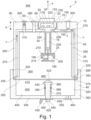
- the generator comprises an enclosure 10 and a catalytic system 15 removably attached to the enclosure.
- the catalytic system comprises a plug 20 and a catalytic housing 25 connected to each other by a connecting member 30.
- the enclosure extends in a longitudinal direction X. It comprises a tank 35 and a cover 40 mounted on the tank. The tank and the cover together delimit an interior enclosure space 45.
- the tank comprises a tank bottom wall 50 defining an upper wall of the enclosure.
- the catalytic system is fixed to the upper wall of the enclosure.
- the upper wall has a window 55 passing through the upper wall from one side to the other in its thickness e.
- the window defines an opening 57 for access to the interior space of the enclosure.
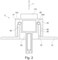
- the plug 20 is engaged in the window 55. It comprises a portion whose shape is complementary to the periphery 60 of the window providing access to the interior space of the enclosure. The plug thus closes the access opening to the interior space of the enclosure.
- the perimeter of the window comprises an element 65 for fixing the enclosure to the catalytic system, which in the illustrated example is a screw thread.
- the cap comprises, on its lateral face, an element 70 for fixing the catalytic system to the enclosure, which is a thread of a complementary shape to the element for fixing the enclosure to the catalytic system.
- the catalytic system can thus be screwed onto the enclosure.
- the enclosure comprises a neck 75 having a generally tubular and hollow shape which defines the window 55.
- the neck comprises a neck wall 80 which extends in the direction of extension from the upper wall and which opens through an opening 57 for access to the interior space of the enclosure surmounting the window.
- the neck wall comprises an outer face 90 which carries a screw thread 95.
- the cap 20 of the catalytic system has a shape complementary to the neck and is screwed onto the neck, to close the opening for access to the interior space of the enclosure.
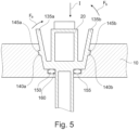
- the catalytic system 15 is fixed to the enclosure 10 by means of a bayonet locking device 100.
- the enclosure comprises grooves 105a-b arranged in the periphery of the window arranged on either side of the plug 20.
- Each groove has an insertion portion 110a-b which extends in the direction of insertion I of the catalytic system and which is extended by a locking portion which extends in a plane transverse to the direction of insertion.
- the plug comprises lugs 115a-b which each project from the side wall of the plug and which are shaped to slide each into one of the corresponding grooves.
- the user inserts the catalytic housing into the interior space of the enclosure through the window 55, then engages each lug in the portion introduction, until the lug abuts the corresponding end 120a-b of the introduction portion. Then, by a rotational movement R around the introduction axis, it introduces each lug into the corresponding locking portion, so that the lug abuts against the side walls of the locking portion and blocks the movement of the catalytic system relative to the enclosure in the direction of introduction.
- the catalytic system can be magnetically attached to the enclosure.
- the plug may comprise a collar 125, arranged outside the enclosure, which is superimposed on the enclosure 10.
- the enclosure is covered by a coating 130 made of a magnetized material, for example a neodymium-based alloy.
- the collar is made of a ferromagnetic metal, for example steel, and is arranged opposite the magnetized coating. The attraction of the magnetized collar on the ferromagnetic coating keeps the catalytic system rigidly fixed on the enclosure.
- a person skilled in the art can easily choose the area of the magnetized coating and the dimensions of the collar so as to ensure the reliability of the connection between the catalytic system and the enclosure, in particular when the interior space of the enclosure is subjected to the pressure of dihydrogen.
- the catalytic system can be removably attached by snap-fastening to the enclosure.
- the plug comprises flexible tabs 135a-b arranged on either side of the plug relative to a median plane containing the longitudinal direction. Each tab extends obliquely relative to the direction of introduction of the catalytic system into the interior space of the enclosure.
- the flexible tab comprises a bead 140a-b shaped to engage in a hollow 145a-b of complementary shape formed in the periphery of the window.
- the user can apply a bending force to each elastic tab, illustrated by the arrows Fa-b so as to extract each bead from the corresponding hollow and can then extract the catalytic system from the enclosure by translation along the insertion direction I.
- the generator of the figures 1 to 5 has an enclosure seal 150.
- the enclosure comprises a shoulder 155, projecting from the periphery of the window, and which defines a bearing surface 160 on which the enclosure seal rests.
- the enclosure seal is compressed between the enclosure 10 and the plug 20, limiting, or even preventing, the leakage of dihydrogen during generation.
- the cap may include the enclosure seal, which is force-fitted against the bottom wall 165 of the cap.
- the catalytic system may also include a mounting member 170 arranged outside the enclosure.
- the mounting member is a tab 175 projecting in the longitudinal direction of the cap. The user can thus take the tab in hand to proceed with the assembly/disassembly of the catalytic system.
- Other mounting members can be considered instead of the tab.
- the catalytic converter housing 25 is housed in the interior enclosure space 45.
- first 190 and second 195 parts movable relative to each other.
- the first and second parts may be movable in translation and/or in rotation, for example along and/or around the longitudinal direction X, respectively.
- the first and second parts define a catalysis chamber 200.
- a catalyst 205 for example at least one metal selected from cobalt, nickel, platinum, ruthenium and their alloys, is arranged on a porous support 210 in the catalysis chamber.
- the catalysis housing comprises a housing seal 215 which is arranged between the first and second parts. In a closed configuration of the catalytic system, the first and second parts are arranged relative to each other so that the catalysis chamber is hermetically sealed, the first and second parts in particular compressing the housing seal. When the enclosure contains a liquid, no intrusion of the liquid is possible into the catalysis chamber.
- the first and second parts are arranged such that the catalysis chamber 200 is in fluid communication with the interior enclosure space 45.
- the liquid comprises the reactant, as will be described below, the reactant can come into contact with the catalyst, so that the hydrogen generation reaction takes place.
- the catalytic system comprises a compartment 220, formed in the cap and hermetically isolated from the interior space of the enclosure, in which an information module 225 is arranged.
- the information module is configured to acquire and store information relating to the state of the catalytic system.
- the information module may comprise an information storage unit, for example a “Flash” type memory or an RFID chip.
- the information may be the nature, in particular the composition, of the catalyst, which may be adapted to the intended application, the date of manufacture of the catalyst, the date of assembly of the catalytic system on the enclosure, the number of openings and closings of the catalytic housing, the number of connections of the generator with a fuel cell.
- the catalytic system comprises, for example, a contact sensor, not shown, for detecting the contacting of the catalytic system on the enclosure, and which is configured to transmit the corresponding information to the information module.
- the information module may comprise a clock and a battery to power the clock and the contact sensor. In this way, it can associate the contacting information with the time of reception of the information to define the date of mounting of the catalytic system on the enclosure. For example, it iterates the counter of the number of times the catalytic system has been mounted on an enclosure.
- the catalytic system further comprises a control unit 230, configured to activate the opening or closing of the catalytic housing, and a measurement unit 235 of a quantity to be controlled.
- the quantity to be controlled is preferably the pressure in the enclosure.
- the quantity to be controlled is preferably the temperature of the hydrogen-carrying liquid.
- the control unit is configured to receive a value of the quantity to be controlled from the measuring unit and, after analyzing said value, to open or close the catalysis chamber, or to maintain the catalysis chamber in the open or closed position.
- the catalytic system comprises the control unit and/or the measuring unit.
- the control unit can be arranged in the compartment. It is of complex and expensive design, and is thus protected.
- the connecting member 30 is a rigid and hollow tube, in which is housed a jack 230 connected to the second part, and controlled by the control unit to actuate the opening or closing of the catalytic system.
- the tube may be flexible, in particular in a variant where the opening and closing of the catalytic system is carried out passively, as described in the application WO 2010/051557 A1 .
- the tank 35 has a side wall 250 which extends from the tank bottom wall 50 along the longitudinal direction to an edge 255 opposite the tank bottom wall.
- the tank comprises a reservoir 260, arranged in the interior enclosure space, which is fixed to the tank.
- the tank comprises a wall which delimits an interior tank space 265.
- the reservoir and the tank have shapes that are substantially homothetic to one another.
- the reservoir thus comprises a tank bottom wall 270 and a tank side wall 275 which are arranged at a distance respectively from the tank bottom wall and the tank side wall.
- the tank side wall extends at its opposite edge to the tank bottom wall by an annular collar 280 fixed to the tank side wall.
- the tank is made of a material that is impermeable to liquid and porous to dihydrogen.
- it is made of a porous hydrophobic membrane based on, for example, polyethylene or polytetrafluoroethylene.
- the enclosure comprises a filling conduit 290, an injection valve 295 and an evacuation valve 300.
- the filling conduit is tubular and hollow. It passes through complementary shaped holes made in the tank and in the reservoir.
- the filling conduit opens at one of its ends into the interior space of the tank and out of the tank at its other end. It is surmounted by a tap, not shown. In the open position of the tap, the filling conduit puts the environment 305 of the generator in fluid communication with the interior space of the enclosure.
- the injection valve 295 allows the injection under pressure of a liquid into the interior space of the tank. It passes through complementary shaped orifices provided in the tank and in the tank, and puts the generator environment and the interior space of the enclosure into fluid communication.
- the injection valve is of the self-sealing type. It includes a check valve 310 to prevent emptying of the tank through the injection valve and to prevent the evacuation of dihydrogen from the interior space of the enclosure.
- the discharge valve 300 purges the enclosure of the dihydrogen formed during the generation reaction. It is housed in an orifice formed in the tank bottom wall and opens into the space formed between the tank bottom wall and the reservoir bottom wall.
- the enclosure and in particular the tank, includes a pressure relief valve, not shown, to prevent any excessive increase in the hydrogen pressure in the enclosure. Beyond a predefined pressure value, dependent on the application, for example equal to 2 bars, the pressure relief valve is opened so as to evacuate the excess hydrogen from the tank and reduce the pressure in the enclosure.
- the pressure relief valve may include a non-return valve or a membrane as described in the application WO2012/058155 A1 .
- the cover 40 is screwed onto the tank.
- the tank and the cover have tubular and hollow portions of shapes complementary to each other.
- the external face 315 of the wall of the tubular portion of the tank and the internal face 320 of the wall of the tubular portion of the cover have screw threads 325-330 of complementary shapes and which are entirely in contact with each other.
- the cover can be magnetized to the tank, or be fixed to the tank by means of a bayonet locking system.
- the enclosure includes a lid gasket 340, sandwiched between the tank and the lid, to prevent leakage of a liquid contained in the interior tank space from the enclosure.
- the cover comprises a container 345 and a seal 350.
- the container has a container bottom wall 355, which defines a lower enclosure wall, and a container side wall 360 which extends from the bottom wall in the longitudinal direction, and is fixed to the tank.
- the side wall also has an annular groove 370 on which the lid is fixed and in which the lid seal is housed.
- the container bottom wall has a recess 375 in which a container opening is provided.
- a hollow tubular skirt 380 extends in the longitudinal direction from the container opening.
- the tubular skirt has a annular groove 385, formed in its internal wall.
- a container seal 390 is housed in the annular groove.
- the container defines an interior container space 400 that contains a reactant 405 for generating the dihydrogen.
- the reactant may be in a solid form or in a liquid form. For example, it is formed of particles, whether agglomerated or not.
- the reagent is for example a hydride or an organic liquid carrying hydrogen.
- the seal is disposed over the opening of the container interior space and seals it 410. Furthermore, the seal is gas-tight and liquid-tight. Thus, in an inactivated configuration of the generator, the seal defines a hermetic barrier which prevents any fluid communication between the container interior space 400 and the reservoir interior space 265. No generation can therefore be carried out in the inactivated configuration of the generator.
- the seal is preferably a film glued into the groove in the side wall of the container.
- the film may be under tension, so as to facilitate its tearing when the generator is activated. It may be made of an alloy or, preferably, of a polymeric material, for example polyethylene or polytetrafluoroethylene.
- the cover comprises a perforation member 420 and a perforation actuator 425.
- the perforation member has a conical and pointed shape. The pointed apex of the cone is arranged at a distance from and opposite the cover in the inactivated configuration.
- the perforation actuator comprises a rod 430 extending in the longitudinal direction and the perforation member 420 is fixed on one end of the rod.
- the rod has a generally cylindrical shape of revolution and comprises an annular collar 435, which in the inactivated configuration, rests on the edge of the skirt which is opposite the container bottom wall.
- the rod is housed in the annular skirt, and is in contact over its entire periphery with the container seal.
- the perforation actuator further comprises a press button 440, of general shape, cylindrical in revolution, arranged at the opposite end of the rod.
- the press button is rigidly fixed on the rod or is made of the same material as the rod. It projects from the bottom wall of the container in the longitudinal direction in the inactivated configuration of the generator.
- a hole 450 is provided in the push button. It passes through the push button from one side to the other in a direction transverse to the longitudinal direction.
- a pin 455 is housed in the hole. It bears on the bottom wall of the container on either side of the push button. Thus, in the inactivated configuration, the rod is fixed relative to the skirt.
- the container comprises a drain valve 460, arranged in a hole passing through the bottom wall of the container from one side to the other, and closing said hole.
- the drain valve places the tank in fluid communication with the generator environment when the pressure in the tank is greater than or equal to a drain pressure. It hermetically isolates the tank from the generator environment when the pressure in the tank is less than the drain pressure.
- the user can implement the following steps.
- the reagent when it is a hydride, it can pour a solvent into the interior space of the reservoir 265, through the filling conduit 290.
- the solvent can be a solution of potassium hydroxide dissolved in water.
- the solvent can comprise a hydride, for example identical to or different from the hydride contained in the container.
- the generator in the activated configuration.
- he can remove the pin 455 from the hole provided in the button 440, then press the button in the longitudinal direction S, so as to bring the perforation member 420 into contact with the seal 350 until the seal breaks.
- the interior space of the container 400 is in fluid communication with the interior space of the reservoir 265.
- the solvent then comes into contact with the reagent to form a solution, for example an aqueous solution of hydrides.
- the control unit can be configured to place the catalyst housing in the open position, such that by bringing the catalyst into contact with the solution, the hydrogen generation reaction takes place.
- the hydrogen thus generated passes through the tank wall and travels between the enclosure wall and the tank wall, as shown by arrow C, to the valve evacuation valve 300 where it is expelled from the generator under the effect of its pressure.
- a transport pipe can be connected at one of its ends to the evacuation valve and at its opposite end to a fuel cell.
- the control unit commands the closure of the housing.
- the pressure in the enclosure decreases as the dihydrogen is evacuated from the generator, until it reaches a predetermined minimum value, for example a pressure value equal to 1.5 bar, from which the control unit commands the opening of the housing again.
- the pressure is absolute, that is to say it is defined relative to a zero reference value in a vacuum.
- Hydrogen generation can continue as long as the reactant concentration in the solution is sufficient.
- the hydride solution comprises non-gaseous products resulting from the hydrogen generation reaction.
- the user can arrange the generator in a cleaning configuration.
- the catalyst housing may be arranged in an open position.
- a cleaning agent for example water, brought to a temperature between 30°C and 70°C, may be injected under a drain pressure, for example greater than 1 bar, into the tank through the injection valve 295.
- the pressurized injection of the cleaning agent at a drain pressure causes the drain valve 460 to open, so that the injection of the cleaning agent causes the solution to be drained from the generator.
- the drain valve may be self-sealing, and depending on the cleaning configuration, a nozzle may be mounted on the drain valve so as to drain the enclosure through the drain valve.
- the cleaning agent may be injected under pressure into the enclosure so as to accelerate the draining.
- the injection of liquid may be continued to dissolve non-gaseous products resulting from the generation of hydrogen which have, for example, accumulated on the tank wall and/or on the container wall.
- the empty removable reagent container can be dismantled and another container containing reagent can be mounted on the tank.
- the catalytic system can be removed from the used tank and can be mounted on another new tank.
- the catalytic system can be extracted through the opening 57 defined by the window 55.
- the access opening to the interior enclosure space can be defined by the opening 465 of the tank opposite the tank bottom wall, and the catalytic system can be extracted through the opening.
- the generator differs from the one illustrated on the Figure 1 in that the enclosure is monolithic.
- the tank has a shape substantially homothetic to the enclosure, and has a tank bottom wall arranged at a distance from the enclosure bottom wall.
- the drain valve passes through both the tank wall and the enclosure wall.
- the reagent for example comprising hydrides in solution in a solvent or comprising an organic liquid carrying hydrogen, can be introduced directly in liquid form into the tank through the filling pipe.
Landscapes
- Chemical & Material Sciences (AREA)
- Organic Chemistry (AREA)
- Health & Medical Sciences (AREA)
- General Health & Medical Sciences (AREA)
- Engineering & Computer Science (AREA)
- Combustion & Propulsion (AREA)
- Inorganic Chemistry (AREA)
- Chemical Kinetics & Catalysis (AREA)
- Feeding, Discharge, Calcimining, Fusing, And Gas-Generation Devices (AREA)
- Fuel Cell (AREA)
- Devices And Processes Conducted In The Presence Of Fluids And Solid Particles (AREA)
Claims (15)
- Diwasserstoffgenerator (5), umfassend eine Einhausung (10) und ein katalytisches System (15),wobei das katalytische System an der Einhausung lösbar starr befestigt ist und ein Katalysegehäuse (25) umfasst, das einen Katalysator (205) für die Reaktion zur Erzeugung von Diwasserstoff ausgehend von einem Reagenz (405) enthält, das unter einem Hydrid, einer organischen Wasserstoffträger-Flüssigkeit und ihren Mischungen ausgewählt ist,wobei die Einhausung einen Einhausungsinnenraum (45) definiert, wobei das Katalysegehäuse mindestens zum Teil eise in dem Einhausungsinnenraum angeordnet ist,wobei der Generator einen Tank zur Aufnahme einer Flüssigkeit umfasst, wobei der Tank eine für die Flüssigkeit dichte und für Diwasserstoff durchlässige Tankwand umfasst, wobei das katalytische System mindestens zum Teil in dem Tank angeordnet ist.
- Generator nach Anspruch 1, wobei das katalytische System an der Einhausung magnetisch befestigt oder an sie anschraubt oder an ihr eingerastet ist oder an der Einhausung mittels einer Vorrichtung vom Typ Bajonettverriegelung befestigt ist.
- Generator nach einem der vorhergehenden Ansprüche, wobei die Einhausung eine Zugangsöffnung (57; 465) zum Einhausungsinnenraum umfasst und wobei das katalytische System dazu ausgebildet ist, bei der Montage bzw. Demontage des katalytischen Systems an der Einhausung durch die Zugangsöffnung zum Einhausungsinnenraum hindurch eingeführt und aus dem Einhausungsinnenraum entnommen zu werden.
- Generator nach einem der vorhergehenden Ansprüche, wobei das katalytische System einen Stopfen (20) umfasst, der lösbar an der Einhausung angebracht ist.
- Generator nach dem vorhergehenden Anspruch, wobei der Stopfen die Zugangsöffnung (57) zum Einhausungsinnenraum verschließt.
- Generator nach den Ansprüchen 3 und 4, wobei die Einhausung eine weitere Zugangsöffnung zum Einhausungsinnenraum definiert, wobei der Stopfen die weitere Zugangsöffnung zum Einhausungsinnenraum verschließt.
- Generator nach einem der Ansprüche 4 bis 7, wobei das Katalysegehäuse im Abstand vom Stopfen angeordnet ist.
- Generator nach einem der vorhergehenden Ansprüche, wobei das Katalysegehäuse erste (190) und zweite (195) Teile umfasst, die gemeinsam eine Katalysekammer (200) definieren, wobei der Katalysator in der Katalysekammer aufgenommen ist, wobei die ersten und zweiten Teile in Bezug aufeinander zwischen einer geschlossenen Stellung, in der die Katalysekammer von dem Einhausungsinnenraum isoliert ist, und einer geöffneten Stellung, in der die Katalysekammer mit dem Einhausungsinnenraum in Fluidverbindung steht, beweglich sind.
- Generator nach einem der vorhergehenden Ansprüche, wobei das katalytische System ein Informationsmodul (225) umfasst, das dazu ausgestaltet ist, Informationen zum Zustand des katalytischen Systems zu erfassen und zu speichern.
- Generator nach einem der vorhergehenden Ansprüche, wobei der Katalysator mindestens ein Metall ist, das unter Kobalt, Nickel, Platin, Ruthenium und ihren Legierungen ausgewählt ist.
- Generator nach einem der vorhergehenden Ansprüche, wobei die Einhausung einen Behälter (35) umfasst und einen Deckel (40), der an dem Behälter lösbar starr befestigt ist und den Behälter verschließt.
- Generator nach dem vorhergehenden Anspruch, wobei der Deckel an den Behälter geschraubt oder an ihm eingerastet oder magnetisch befestigt ist oder an dem Behälter mittels eines Bajonettverriegelungssystems befestigt ist.
- Generator nach dem vorhergehenden Anspruch, wobei der Deckel ein Behältnis (345) umfasst und einen Verschluss (350), zum Beispiel eine insbesondere metallische oder thermoplastische Folie, der das Behältnis hermetisch verschließt, wobei das Behältnis das Reagenz (405) enthält, bevorzugt in einer festen Form.
- Generator nach dem vorhergehenden Anspruch, umfassend ein Durchstoßungsorgan (420), das dazu ausgestaltet ist, den Verschluss zu zerreißen, und bevorzugt einen Durchstoßungsaktor (425), der dazu ausgestaltet ist, das Durchstoßungsorgan so zu verlagern, dass es den Verschluss zerreißt.
- Generator nach dem vorhergehenden Anspruch, wobei der Deckel den Durchstoßungsaktor und/oder das Durchstoßungsorgan umfasst.
Applications Claiming Priority (2)
| Application Number | Priority Date | Filing Date | Title |
|---|---|---|---|
| FR1909036A FR3099854B1 (fr) | 2019-08-07 | 2019-08-07 | Générateur de dihydrogène réutilisable |
| PCT/EP2020/071587 WO2021023636A1 (fr) | 2019-08-07 | 2020-07-30 | Générateur de dihydrogène réutilisable |
Publications (3)
| Publication Number | Publication Date |
|---|---|
| EP4010285A1 EP4010285A1 (de) | 2022-06-15 |
| EP4010285B1 true EP4010285B1 (de) | 2025-04-23 |
| EP4010285C0 EP4010285C0 (de) | 2025-04-23 |
Family
ID=68987877
Family Applications (1)
| Application Number | Title | Priority Date | Filing Date |
|---|---|---|---|
| EP20746669.9A Active EP4010285B1 (de) | 2019-08-07 | 2020-07-30 | Wiederverwendbarer dihydrogengenerator |
Country Status (4)
| Country | Link |
|---|---|
| US (1) | US12545577B2 (de) |
| EP (1) | EP4010285B1 (de) |
| FR (1) | FR3099854B1 (de) |
| WO (1) | WO2021023636A1 (de) |
Families Citing this family (1)
| Publication number | Priority date | Publication date | Assignee | Title |
|---|---|---|---|---|
| FR3128455B1 (fr) * | 2021-10-22 | 2024-01-05 | Commissariat Energie Atomique | Melanges de liquides organiques porteurs d'hydrogene, leurs utilisations pour le transport et le stockage d’hydrogene, et les procedes de generation d’hydrogene les utilisant |
Family Cites Families (11)
| Publication number | Priority date | Publication date | Assignee | Title |
|---|---|---|---|---|
| US20060185242A1 (en) | 2003-03-28 | 2006-08-24 | Cha Seung S | Hydrogen gas generator |
| FR2893606B1 (fr) * | 2005-11-24 | 2008-04-25 | Commissariat Energie Atomique | Generateur d'hydrogene et pile a combustible mettant en oeuvre un tel generateur |
| US9016319B2 (en) | 2007-08-22 | 2015-04-28 | Societe Bic | Relief valves for fuel cell systems |
| RU2011117110A (ru) * | 2008-11-03 | 2012-11-10 | Сосьете Бик (Fr) | Генерирующие водород баллончики топливного элемента |
| US8986404B2 (en) | 2009-11-03 | 2015-03-24 | Societe Bic | Gas generator with starter mechanism and catalyst shield |
| US20100150824A1 (en) * | 2008-11-21 | 2010-06-17 | Lynntech, Inc. | Hydrogen generator with reactant dilution scheme |
| EP3224196B1 (de) | 2014-11-28 | 2018-08-22 | Ulusal Bor Arastirma Enstitusu (Boren) | Kartuschenstruktur zur erzeugung von wasserstoffgas |
| FR3072303B1 (fr) | 2017-10-18 | 2019-11-01 | Commissariat A L'energie Atomique Et Aux Energies Alternatives | Appareil pour generer un gaz |
| FR3072304B1 (fr) * | 2017-10-18 | 2019-11-01 | Commissariat A L'energie Atomique Et Aux Energies Alternatives | Dispositif de generation de gaz |
| FR3095079B1 (fr) * | 2019-04-09 | 2021-07-30 | Commissariat Energie Atomique | Dispositif de génération d’un gaz |
| FR3099853B1 (fr) * | 2019-08-07 | 2021-11-05 | Commissariat Energie Atomique | Générateur de dihydrogène réutilisable |
-
2019
- 2019-08-07 FR FR1909036A patent/FR3099854B1/fr active Active
-
2020
- 2020-07-30 WO PCT/EP2020/071587 patent/WO2021023636A1/fr not_active Ceased
- 2020-07-30 EP EP20746669.9A patent/EP4010285B1/de active Active
- 2020-07-30 US US17/632,782 patent/US12545577B2/en active Active
Also Published As
| Publication number | Publication date |
|---|---|
| US12545577B2 (en) | 2026-02-10 |
| US20220315420A1 (en) | 2022-10-06 |
| WO2021023636A1 (fr) | 2021-02-11 |
| FR3099854B1 (fr) | 2021-10-22 |
| FR3099854A1 (fr) | 2021-02-12 |
| EP4010285A1 (de) | 2022-06-15 |
| EP4010285C0 (de) | 2025-04-23 |
Similar Documents
| Publication | Publication Date | Title |
|---|---|---|
| BE1013199A3 (fr) | Conteneur pour renfermer separement deux substances differentes. | |
| CN107907278B (zh) | 一种电力变压器储油柜胶囊的密封性检测方法 | |
| EP4010285B1 (de) | Wiederverwendbarer dihydrogengenerator | |
| EP4010284B1 (de) | Wiederverwendbarer dihydrogengenerator | |
| RU2008115151A (ru) | Топливный баллончик для топливных элементов | |
| FR3072303B1 (fr) | Appareil pour generer un gaz | |
| CN110373411A (zh) | 一种痕量dna提取胶囊 | |
| EP3697729B1 (de) | Vorrichtung zur erzeugung von gas | |
| JP2010027621A (ja) | 電気化学装置 | |
| FR3099855A1 (fr) | Générateur de dihydrogène réutilisable | |
| JP2010274966A (ja) | 液体充填装置、及び、待機方法 | |
| EP1153277A1 (de) | Verpackung mit ständiger kontrolle ihrer dichtigkeit | |
| CN220453398U (zh) | 一种氢气储存罐用氢气泄漏报警装置 | |
| JP7443484B2 (ja) | 消火装置の保存容器およびスパウト押さえ、消火装置の気密容器 | |
| EP3947194A1 (de) | Recyclefähige aerosoldose mit druckentlastungssystem und werkzeug zum entspannen einer solchen dose | |
| WO2021037939A1 (fr) | Dispositif de génération d'un gaz | |
| CN220781005U (zh) | 一种可视液位点胶压力桶 | |
| JP2000294253A (ja) | 外部水素除去剤を有する電池 | |
| CN222629885U (zh) | 含硫气水样品密封存储装置 | |
| FR2553562A1 (fr) | Generateur d'un produit radioactif ou toxique utilisable notamment comme generateur d'iode radioactif | |
| RU75960U1 (ru) | Устройство для получения газов | |
| FR2938647A1 (fr) | Installation de controle de l'etancheite de flacons, notamment de flacons de parfum equipes d'une pompe | |
| FR3155584A1 (fr) | Dispositif de prélèvement de gaz | |
| JP2008045021A (ja) | 液体燃料精製方法及び液体燃料精製システム | |
| EP4194363A1 (de) | Behälter zur aufbewahrung und konservierung einer kartusche mit einer kanüle zur abgabe eines polymerisierbaren harzes |
Legal Events
| Date | Code | Title | Description |
|---|---|---|---|
| STAA | Information on the status of an ep patent application or granted ep patent |
Free format text: STATUS: UNKNOWN |
|
| STAA | Information on the status of an ep patent application or granted ep patent |
Free format text: STATUS: THE INTERNATIONAL PUBLICATION HAS BEEN MADE |
|
| PUAI | Public reference made under article 153(3) epc to a published international application that has entered the european phase |
Free format text: ORIGINAL CODE: 0009012 |
|
| STAA | Information on the status of an ep patent application or granted ep patent |
Free format text: STATUS: REQUEST FOR EXAMINATION WAS MADE |
|
| 17P | Request for examination filed |
Effective date: 20220131 |
|
| AK | Designated contracting states |
Kind code of ref document: A1 Designated state(s): AL AT BE BG CH CY CZ DE DK EE ES FI FR GB GR HR HU IE IS IT LI LT LU LV MC MK MT NL NO PL PT RO RS SE SI SK SM TR |
|
| DAV | Request for validation of the european patent (deleted) | ||
| DAX | Request for extension of the european patent (deleted) | ||
| RAP3 | Party data changed (applicant data changed or rights of an application transferred) |
Owner name: COMMISSARIAT A L'ENERGIE ATOMIQUE ET AUX ENERGIESALTERNATIVES |
|
| GRAP | Despatch of communication of intention to grant a patent |
Free format text: ORIGINAL CODE: EPIDOSNIGR1 |
|
| STAA | Information on the status of an ep patent application or granted ep patent |
Free format text: STATUS: GRANT OF PATENT IS INTENDED |
|
| INTG | Intention to grant announced |
Effective date: 20250210 |
|
| GRAS | Grant fee paid |
Free format text: ORIGINAL CODE: EPIDOSNIGR3 |
|
| GRAA | (expected) grant |
Free format text: ORIGINAL CODE: 0009210 |
|
| STAA | Information on the status of an ep patent application or granted ep patent |
Free format text: STATUS: THE PATENT HAS BEEN GRANTED |
|
| AK | Designated contracting states |
Kind code of ref document: B1 Designated state(s): AL AT BE BG CH CY CZ DE DK EE ES FI FR GB GR HR HU IE IS IT LI LT LU LV MC MK MT NL NO PL PT RO RS SE SI SK SM TR |
|
| REG | Reference to a national code |
Ref country code: GB Ref legal event code: FG4D Free format text: NOT ENGLISH |
|
| REG | Reference to a national code |
Ref country code: CH Ref legal event code: EP |
|
| REG | Reference to a national code |
Ref country code: DE Ref legal event code: R096 Ref document number: 602020049964 Country of ref document: DE |
|
| REG | Reference to a national code |
Ref country code: IE Ref legal event code: FG4D Free format text: LANGUAGE OF EP DOCUMENT: FRENCH |
|
| U01 | Request for unitary effect filed |
Effective date: 20250513 |
|
| U07 | Unitary effect registered |
Designated state(s): AT BE BG DE DK EE FI FR IT LT LU LV MT NL PT RO SE SI Effective date: 20250523 |
|
| U20 | Renewal fee for the european patent with unitary effect paid |
Year of fee payment: 6 Effective date: 20250818 |
|
| PG25 | Lapsed in a contracting state [announced via postgrant information from national office to epo] |
Ref country code: ES Free format text: LAPSE BECAUSE OF FAILURE TO SUBMIT A TRANSLATION OF THE DESCRIPTION OR TO PAY THE FEE WITHIN THE PRESCRIBED TIME-LIMIT Effective date: 20250423 |
|
| PG25 | Lapsed in a contracting state [announced via postgrant information from national office to epo] |
Ref country code: NO Free format text: LAPSE BECAUSE OF FAILURE TO SUBMIT A TRANSLATION OF THE DESCRIPTION OR TO PAY THE FEE WITHIN THE PRESCRIBED TIME-LIMIT Effective date: 20250723 Ref country code: GR Free format text: LAPSE BECAUSE OF FAILURE TO SUBMIT A TRANSLATION OF THE DESCRIPTION OR TO PAY THE FEE WITHIN THE PRESCRIBED TIME-LIMIT Effective date: 20250724 |
|
| PG25 | Lapsed in a contracting state [announced via postgrant information from national office to epo] |
Ref country code: PL Free format text: LAPSE BECAUSE OF FAILURE TO SUBMIT A TRANSLATION OF THE DESCRIPTION OR TO PAY THE FEE WITHIN THE PRESCRIBED TIME-LIMIT Effective date: 20250423 |
|
| U1N | Appointed representative for the unitary patent procedure changed after the registration of the unitary effect |
Representative=s name: IPSILON; FR |
|
| PGFP | Annual fee paid to national office [announced via postgrant information from national office to epo] |
Ref country code: GB Payment date: 20250724 Year of fee payment: 6 |
|
| PG25 | Lapsed in a contracting state [announced via postgrant information from national office to epo] |
Ref country code: HR Free format text: LAPSE BECAUSE OF FAILURE TO SUBMIT A TRANSLATION OF THE DESCRIPTION OR TO PAY THE FEE WITHIN THE PRESCRIBED TIME-LIMIT Effective date: 20250423 |
|
| PG25 | Lapsed in a contracting state [announced via postgrant information from national office to epo] |
Ref country code: RS Free format text: LAPSE BECAUSE OF FAILURE TO SUBMIT A TRANSLATION OF THE DESCRIPTION OR TO PAY THE FEE WITHIN THE PRESCRIBED TIME-LIMIT Effective date: 20250723 |
|
| PG25 | Lapsed in a contracting state [announced via postgrant information from national office to epo] |
Ref country code: IS Free format text: LAPSE BECAUSE OF FAILURE TO SUBMIT A TRANSLATION OF THE DESCRIPTION OR TO PAY THE FEE WITHIN THE PRESCRIBED TIME-LIMIT Effective date: 20250823 |
|
| PG25 | Lapsed in a contracting state [announced via postgrant information from national office to epo] |
Ref country code: SM Free format text: LAPSE BECAUSE OF FAILURE TO SUBMIT A TRANSLATION OF THE DESCRIPTION OR TO PAY THE FEE WITHIN THE PRESCRIBED TIME-LIMIT Effective date: 20250423 |
|
| PG25 | Lapsed in a contracting state [announced via postgrant information from national office to epo] |
Ref country code: CZ Free format text: LAPSE BECAUSE OF FAILURE TO SUBMIT A TRANSLATION OF THE DESCRIPTION OR TO PAY THE FEE WITHIN THE PRESCRIBED TIME-LIMIT Effective date: 20250423 |
|
| PG25 | Lapsed in a contracting state [announced via postgrant information from national office to epo] |
Ref country code: SK Free format text: LAPSE BECAUSE OF FAILURE TO SUBMIT A TRANSLATION OF THE DESCRIPTION OR TO PAY THE FEE WITHIN THE PRESCRIBED TIME-LIMIT Effective date: 20250423 |