EP4009835B1 - Seat, particularly a rocking chair - Google Patents
Seat, particularly a rocking chair Download PDFInfo
- Publication number
- EP4009835B1 EP4009835B1 EP20750295.6A EP20750295A EP4009835B1 EP 4009835 B1 EP4009835 B1 EP 4009835B1 EP 20750295 A EP20750295 A EP 20750295A EP 4009835 B1 EP4009835 B1 EP 4009835B1
- Authority
- EP
- European Patent Office
- Prior art keywords
- seat
- frame part
- stop member
- shaped part
- resilient
- Prior art date
- Legal status (The legal status is an assumption and is not a legal conclusion. Google has not performed a legal analysis and makes no representation as to the accuracy of the status listed.)
- Active
Links
- 239000000463 material Substances 0.000 claims description 25
- 238000013016 damping Methods 0.000 claims description 16
- 125000006850 spacer group Chemical group 0.000 claims description 10
- 229920001971 elastomer Polymers 0.000 claims description 3
- 239000004033 plastic Substances 0.000 claims description 3
- 229920003023 plastic Polymers 0.000 claims description 3
- 239000005060 rubber Substances 0.000 claims description 2
- 239000004744 fabric Substances 0.000 description 14
- 241000446313 Lamella Species 0.000 description 5
- 230000036544 posture Effects 0.000 description 5
- 238000004026 adhesive bonding Methods 0.000 description 2
- 230000007423 decrease Effects 0.000 description 2
- 238000001125 extrusion Methods 0.000 description 2
- 238000005728 strengthening Methods 0.000 description 2
- 230000007704 transition Effects 0.000 description 2
- 239000000853 adhesive Substances 0.000 description 1
- 230000001070 adhesive effect Effects 0.000 description 1
- 239000000806 elastomer Substances 0.000 description 1
- 229920003052 natural elastomer Polymers 0.000 description 1
- 229920001194 natural rubber Polymers 0.000 description 1
- 238000005457 optimization Methods 0.000 description 1
- 230000000630 rising effect Effects 0.000 description 1
- 239000011435 rock Substances 0.000 description 1
- 238000006748 scratching Methods 0.000 description 1
- 230000002393 scratching effect Effects 0.000 description 1
- 239000007787 solid Substances 0.000 description 1
- 229920003051 synthetic elastomer Polymers 0.000 description 1
- 239000005061 synthetic rubber Substances 0.000 description 1
- 230000003313 weakening effect Effects 0.000 description 1
Images


Classifications
-
- A—HUMAN NECESSITIES
- A47—FURNITURE; DOMESTIC ARTICLES OR APPLIANCES; COFFEE MILLS; SPICE MILLS; SUCTION CLEANERS IN GENERAL
- A47C—CHAIRS; SOFAS; BEDS
- A47C3/00—Chairs characterised by structural features; Chairs or stools with rotatable or vertically-adjustable seats
- A47C3/02—Rocking chairs
- A47C3/029—Rocking chairs with curved rocking members resting on the floor
-
- A—HUMAN NECESSITIES
- A47—FURNITURE; DOMESTIC ARTICLES OR APPLIANCES; COFFEE MILLS; SPICE MILLS; SUCTION CLEANERS IN GENERAL
- A47C—CHAIRS; SOFAS; BEDS
- A47C3/00—Chairs characterised by structural features; Chairs or stools with rotatable or vertically-adjustable seats
- A47C3/02—Rocking chairs
- A47C3/03—Locking members
-
- A—HUMAN NECESSITIES
- A47—FURNITURE; DOMESTIC ARTICLES OR APPLIANCES; COFFEE MILLS; SPICE MILLS; SUCTION CLEANERS IN GENERAL
- A47C—CHAIRS; SOFAS; BEDS
- A47C3/00—Chairs characterised by structural features; Chairs or stools with rotatable or vertically-adjustable seats
- A47C3/02—Rocking chairs
-
- A—HUMAN NECESSITIES
- A47—FURNITURE; DOMESTIC ARTICLES OR APPLIANCES; COFFEE MILLS; SPICE MILLS; SUCTION CLEANERS IN GENERAL
- A47C—CHAIRS; SOFAS; BEDS
- A47C5/00—Chairs of special materials
- A47C5/04—Metal chairs, e.g. tubular
-
- A—HUMAN NECESSITIES
- A47—FURNITURE; DOMESTIC ARTICLES OR APPLIANCES; COFFEE MILLS; SPICE MILLS; SUCTION CLEANERS IN GENERAL
- A47C—CHAIRS; SOFAS; BEDS
- A47C5/00—Chairs of special materials
- A47C5/04—Metal chairs, e.g. tubular
- A47C5/06—Special adaptation of seat upholstery or fabric for attachment to tubular chairs
-
- A—HUMAN NECESSITIES
- A47—FURNITURE; DOMESTIC ARTICLES OR APPLIANCES; COFFEE MILLS; SPICE MILLS; SUCTION CLEANERS IN GENERAL
- A47C—CHAIRS; SOFAS; BEDS
- A47C7/00—Parts, details, or accessories of chairs or stools
- A47C7/002—Chair or stool bases
-
- A—HUMAN NECESSITIES
- A47—FURNITURE; DOMESTIC ARTICLES OR APPLIANCES; COFFEE MILLS; SPICE MILLS; SUCTION CLEANERS IN GENERAL
- A47C—CHAIRS; SOFAS; BEDS
- A47C7/00—Parts, details, or accessories of chairs or stools
- A47C7/36—Support for the head or the back
- A47C7/40—Support for the head or the back for the back
-
- F—MECHANICAL ENGINEERING; LIGHTING; HEATING; WEAPONS; BLASTING
- F16—ENGINEERING ELEMENTS AND UNITS; GENERAL MEASURES FOR PRODUCING AND MAINTAINING EFFECTIVE FUNCTIONING OF MACHINES OR INSTALLATIONS; THERMAL INSULATION IN GENERAL
- F16F—SPRINGS; SHOCK-ABSORBERS; MEANS FOR DAMPING VIBRATION
- F16F9/00—Springs, vibration-dampers, shock-absorbers, or similarly-constructed movement-dampers using a fluid or the equivalent as damping medium
- F16F9/003—Dampers characterised by having pressure absorbing means other than gas, e.g. sponge rubber
-
- A—HUMAN NECESSITIES
- A47—FURNITURE; DOMESTIC ARTICLES OR APPLIANCES; COFFEE MILLS; SPICE MILLS; SUCTION CLEANERS IN GENERAL
- A47C—CHAIRS; SOFAS; BEDS
- A47C1/00—Chairs adapted for special purposes
-
- F—MECHANICAL ENGINEERING; LIGHTING; HEATING; WEAPONS; BLASTING
- F16—ENGINEERING ELEMENTS AND UNITS; GENERAL MEASURES FOR PRODUCING AND MAINTAINING EFFECTIVE FUNCTIONING OF MACHINES OR INSTALLATIONS; THERMAL INSULATION IN GENERAL
- F16F—SPRINGS; SHOCK-ABSORBERS; MEANS FOR DAMPING VIBRATION
- F16F2230/00—Purpose; Design features
- F16F2230/0052—Physically guiding or influencing
- F16F2230/007—Physically guiding or influencing with, or used as an end stop or buffer; Limiting excessive axial separation
Definitions
- the invention relates to a seat, particularly a rocking chair, comprising a frame, a seat surface and a backrest, wherein the frame comprises two lower frame parts extending forward from the backrest and each having a curved progression which is convex in downward direction.
- the invention relates particularly to a seat which gives a user, for instance someone playing video games, the option of adopting different sitting postures.
- Such seats are known for example from US2054487A , US2008/100120A1 and US2005/275262A1 .
- a seat which is used for playing video games must thus be suitable for supporting different sitting postures. This requirement is met by a rocking chair, in which a user can move further forward or conversely further rearward, depending on the stage of the game, while sitting in the seat.
- a rocking chair in which a user can move further forward or conversely further rearward, depending on the stage of the game, while sitting in the seat.
- it will be moved reciprocally intensively and regularly. This entails the risk of damage to, particularly scratching of, a floor on which the lower frame parts of the seat rest.
- the often sudden movements moreover entail the risk of a body part, particularly a hand or foot of a player or of someone in the vicinity of the seat, for instance a spectator, becoming caught between one of the lower frame parts and the floor.
- the invention has for its object to provide a rocking chair which meets these requirements.
- the at least one stop member can be resiliently deformable.
- the resilient deformability may be achieved through a suitable structural design of the stop member.
- the at least one stop member can here have a variable height as seen in longitudinal direction of the relevant frame part.
- the stop member can thus deform gradually.
- the height can increase gradually in the direction of the relevant outer end, whereby the stop member functions as a type of wedge under the frame part and wholly or partially fills up a space under the rising outer end of the lower frame part.
- the stop members Since in an unloaded state the stop members almost completely negate the curvature of the lower frame part. Only when a user lower himself into the seat does this become mobile since the stop members are deformed under the influence of the weight of the user. Since the deformation of the stop members, and thereby the mobility of the seat depends on the weight of the user, the seat is safe for use by children. In fact, the stop members will restrict movements of relatively lightweight user to a larger extent than those of heavier users, such as adults.
- the at least one stop member may have a side facing the ground during use, which defines a variable radius of curvature.
- the radius of curvature may decrease from the centre of the lower frame part in the direction of the outer ends thereof.
- the stop member is relatively flat near the centre of the lower frame part, and more strongly curved near the relevant outer end.
- a part of the at least one stop member which protrudes outside the lower frame part has an open section.
- Such an open section is formed in that the at least one stop member comprises a number of chambers.
- a suitable choice of position and dimensions of the chambers enables the deformability of the stop member to be designed specifically for a determined rocking behaviour.
- At least one of the chambers can be filled with a material differing from the material of the at least one stop member.
- the at least one stop member comprises an upper band connected to the frame part, a number of spacers protruding from the upper band and defining the chambers between them, and a lower band connected to free ends of the spacers.
- At least a part of the spacers can be bent or curved.
- the at least one stop member may be made of a resilient and/or damping material. Such a material may contribute to the resilient deformability of the stop member, in addition to the structural design.
- the lower frame parts can each be covered on an underside thereof with a resilient and/or damping material. This prevents wear of the ground surface, while additionally improving the comfort of the seat during movements. The consequences of inadvertently becoming trapped are moreover reduced by such a layer.
- a resilient and/or damping material can be applied together with or instead of a stop member.
- the resilient and/or damping material can be a shaped part connected to the relevant frame part.
- the resilient and/or damping material can thus be arranged in simple manner.
- the shaped part When the shaped part is connected releasably to the relevant frame part, it can be exchanged in simple manner, for instance in the case of wear.
- the shaped part can comprise fastening elements co-acting with the frame part, for instance protrusions which can be pressed into openings in the frame part.
- the shaped part it is possible to envisage the shaped part being connected non-releasably to the seat, for instance by glueing.
- the shaped part extends from a position close to a front outer end of the relevant frame part to a position close to a rear outer end thereof, so that the frame part is protected over substantially its whole length.
- the shaped part can here comprise a number of segments which connect to each other in longitudinal direction of the relevant frame part and are easier to handle than a single shaped part having the length of a frame part.
- the segments can here comprise, as seen in longitudinal direction of the relevant frame part, a front segment, a rear segment and at least one middle segment placed therebetween.
- the shaped part can be formed integrally, whereby it can be mounted under the seat in simple manner.
- the shaped part has over at least a part of its length a substantially constant cross-section.
- a shaped part with constant cross-section can be manufactured in simple manner by means of extrusion.
- the shaped part can tightly enclose the relevant frame part at least partially in cross-section.
- the shaped part can have on its upper side a recess for receiving the relevant frame part.
- the shaped part can have a profile on its underside.
- the resilient and/or damping material can comprise rubber.
- the resilient and/or damping material comprising a plastic, for instance an elastomer such as TPU.
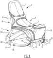
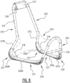
- a seat 1, particularly a rocking chair comprises a frame 2, a seat surface 4 and a backrest 5.
- the frame 2 is tubular and tensioned thereover is a cloth 3 which forms the seat surface 4 and the backrest 5 ( Fig. 1-3 ).
- Frame 2 has two lower frame parts 6L, 6R extending in longitudinal direction of the seat, so in forward direction from backrest 5.
- Each of the lower frame parts 6L, 6R has a curved progression which is convex in downward direction, this enabling seat 1 to rock.
- Each lower frame part 6L, 6R has a front outer end 7L, 7R and a rear outer end 8L, 8R.
- a front transverse frame part 9 connects the two lower frame parts 6L, 6R at their front outer ends 7L, 7R, while a rear transverse frame part 10 connects the lower frame parts 6L, 6R at their rear outer end 8L, 8R.
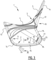
- the front and rear transverse frame parts 9, 10 extend substantially transversely upward from the lower frame parts 6L, 6R and in the shown example each have a curved progression which is convex in upward direction.
- the rear transverse frame part 10 here protrudes further above lower frame parts 6L, 6R than the front transverse frame part 9, so that rear transverse frame part 10 is able to support the upper side of backrest 5.
- Rear transverse frame part 10 here first has on either side a lower segment 11L, 11R which connects to the lower frame part 6L, 6R and which extends substantially parallel to the front transverse frame part 9.
- An upper segment 12 then connects to the two lower segments 11L, 11R, which upper segment extends rearward, so in opposite direction to the front transverse frame part 9.
- the backrest 5 of the seat is hereby as it were shifted forward relative to the lower frame parts 6L, 6R, whereby someone sitting on seat 1 is prevented from falling backward when he or she leans against backrest 5.
- frame 2 thus has a substantially U-shaped cross-section, wherein one of the legs is longer than the other, while in front or rear view the transverse frame parts 9, 10 each have a reverse U-shape.
- the transitions between the lower frame parts 6L, 6R and the transverse frame parts 9, 10 otherwise also each have a curved progression so that frame 2 as a whole takes the form of a loop bent upward on the front and rear side ( Fig. 9 ).
- Cloth 3 is for this purpose provided close to its front side and rear side with folded-over end parts 13, 14 in which the upper ends of the front and rear transverse frame parts 9, 10 can be received. Cloth 3 is thus tensioned on frame 2 in longitudinal direction of seat 1.
- cloth 3 is tensioned in transverse direction of seat 1 toward the two lower frame parts 6L, 6R.
- cloth 3 is provided on either side with a tensioning member 16L, 16R which extend to points of attachment 18 at the position of the rear outer ends 8L, 8R of the lower frame parts 6L, 6R.
- These points of attachment 18 here take the form of brackets which are arranged in the transition between lower frame parts 6L, 6R and rear transverse frame part 10 and around which free outer ends of the tensioning members 16L, 16R are folded.
- the free outer end of tensioning member 16R is here provided with a bracket 22 through which the free outer end 23 of tensioning member 16L is placed, after which it is fastened to itself by means of a fastening member 24.
- Cloth 3 is further provided with two tensioning members 15L, 15R which are connected to each other behind the transverse frame part 10.
- tensioning member 15R has a bracket 27 through which a free outer end 28 of tensioning member 15L is placed, after which this is likewise fixed to itself using a fastening member 29.
- cloth 3 when tensioned in frame 2, forms a double-curved surface.
- the thus formed rocking chair 1 is suitable for playing video games.
- a player can here sit on seat 1 with his or her feet on either side of the lower frame parts 6L, 6R and find a suitable sitting posture, upright, leaning forward or leaning back, irrespective of the game and the stage of the game.
- the point where seat 1 makes contact with the ground surface shifts forward or rearward here.
- the lower frame parts 6L, 6R are each covered on their underside with a resilient and/or damping material, for instance a soft plastic or natural or synthetic rubber.
- This resilient and/or damping material is here arranged on the lower frame parts 6L, 6R in the form of shaped parts 21 which extend from the front outer end 7L, 7R to the rear outer end 8L, 8R of each lower frame part 6L, 6R.
- the shaped parts even extend from the front transverse frame part 9 to the rear transverse frame part 10.
- each shaped part 21 can be connected releasably to the lower frame parts 6L, 6R so that they can be replaced in the case of wear.
- each shaped part 21 can for instance be provided with a number of fastening elements, for instance upward directed protrusions 42 ( Fig. 11 ), which can be inserted into openings in the underside of the corresponding frame parts 6L, 6R.
- the shaped parts 21 partially enclose the corresponding frame parts 6L, 6R so that a strong connection is formed.
- each shaped part 21 comprises here a body 40 in which on the upper side a recess 41 is formed, the cross-section of which corresponds to that of the corresponding frame part 6L, 6R.
- Each shaped part 21 is further provided on its underside with a profile in order to prevent shifting of seat 1 during the reciprocal movement.
- the profile comprises a series of parallel rectangular blocks 25 which are separated from each other by grooves 26.
- shaped parts 21 have a substantially constant cross-sectional form over their whole length, and can thus for instance be manufactured by extrusion.
- each shaped part 21 is here a whole extending over the length of the corresponding frame part 6L, 6R, it is also possible to envisage each shaped part 21 being constructed from a number of segments which are placed contiguously one behind the other.
- a front and rear segment can here be used, the curvature of which is adapted to that of the front and rear ends 7, 8 of the lower frame part 6.
- One or more substantially straight middle segments can be placed therebetween in order to achieve the desired length.
- the frame 102 is provided not with one but with two pairs of points of attachment 117, 118 which are arranged close to respectively the front outer ends 107L, 107R and the rear outer ends 108L, 108R of lower frame parts 106L, 106R ( Fig. 4 ).
- cloth 103 is provided with two pairs of tensioning members 115L, 115R and 116L, 116R, which are tensioned toward the front and rear points of attachment 117, 118 and the ends 123, 128 of which are folded over and fastened, for instance with velcro tape.
- the cloth 203 is provided, as in the first example, with two tensioning members 216 which in turn are attached to points of attachment 218 close to the rear outer ends 208L, 208R of the lower frame parts 206L, 206R.
- These tensioning members 216 are not connected to each other but, as in the second embodiment, their free outer ends 223 are folded over and fastened to themselves.
- the front and rear transverse frame parts 209, 210 are in this embodiment strengthened by arranging cross braces therein.
- a transverse rod 235 is arranged between the legs of the reverse U-shaped front frame part 209 ( Fig. 8 ).
- a transverse rod 236 is here further arranged between the legs of the reverse U-shaped rear frame part 210, which rod co-acts with a strengthening profile 237 which is folded over the upper side of the rear transverse frame part 210.
- Strengthening profile 237 further serves as carrier for a headrest 238 which is arranged on the upper side of backrest 205.
- the cloth 203 is further provided on either side with pockets 219 for receiving a mobile phone of a player, while cloth 203 has on both front side 213 and rear side 214 a pocket 220 for receiving a control unit for a video game.
- respective stop members 230, 231 are in each case formed close to the front and rear outer ends 207, 208 of the left-hand and right-hand lower frame parts 206L, 206R. These stop members 230, 231 brake excessive forward or rearward rocking movements and prevent seat 201 from falling over.
- each stop member 230, 231 has a variable height as seen in longitudinal direction of the relevant frame part 206, whereby the spaces under the upward curved front and rear outer ends 207, 208 of lower frame part 206 are as it were filled in.
- Each stop member 230, 231 also has a radius of curvature which is variable in longitudinal direction of the frame part 206, and which progressively decreases from the centre of the frame part 206 towards the front and rear outer ends 207, 208, respectively. In this way a gradually increasing resistance to further deformation, and thereby to further rocking motion is formed.
- stop members 230, 231 are incorporated in the shaped part 221 of resilient and/or damping material, and are themselves also resiliently deformable.
- each stop member 230, 231 is provided with an open section which comprises a number of chambers 239.
- each stop member 230, 231 is formed by a resiliently flexible strip or lower band 232 which is connected by means of a number of resiliently flexible spacers or lamella 233 to a strip or upper band 234 mounted on lower frame part 206.
- Spacers or lamella 233, these defining chambers 239 therebetween, have different lengths or heights so that the distance between lower and upper band 232, 234 varies in longitudinal direction of lower frame part 206.
- Each stop 230, 231 thus in fact forms a protrusion under the corresponding curved outer end 207, 208.
- chambers 239 weakens the stop member 230, 231 locally, whereby the deformability can be controlled.
- some chambers 239 being filled with a material other than the material of the stop member 230, 231, so that chambers 239 form a less serious weakening, or conversely a stiffening, when the other material is stiffer.
Description
- The invention relates to a seat, particularly a rocking chair, comprising a frame, a seat surface and a backrest, wherein the frame comprises two lower frame parts extending forward from the backrest and each having a curved progression which is convex in downward direction. The invention relates particularly to a seat which gives a user, for instance someone playing video games, the option of adopting different sitting postures. Such seats are known for example from
US2054487A ,US2008/100120A1 andUS2005/275262A1 . - Up to this point players of video games have generally sat on a sofa in front of a screen, holding a controller in their hands. Video games on mobile devices, for instance tablets or smartphones, are also often played while sitting on a sofa. The sitting posture of a player depends here on the video game. A player playing a racing game will thus lean relatively far back, while a player playing for instance a football game will sit more upright and leaning forward. A player can even change their sitting posture while playing a game. In the case of football games, it is thus for instance common to lean forward more when attacking, and conversely lean back more when defending.
- A seat which is used for playing video games must thus be suitable for supporting different sitting postures. This requirement is met by a rocking chair, in which a user can move further forward or conversely further rearward, depending on the stage of the game, while sitting in the seat. When such a seat is used for playing video games, it will be moved reciprocally intensively and regularly. This entails the risk of damage to, particularly scratching of, a floor on which the lower frame parts of the seat rest. The often sudden movements moreover entail the risk of a body part, particularly a hand or foot of a player or of someone in the vicinity of the seat, for instance a spectator, becoming caught between one of the lower frame parts and the floor. In addition, rocking movements of a player which are too sudden or too forceful entail the risk of the seat tipping forward or backward, wherein the latter in particular can be dangerous. Finally, it is advantageous for the seat to also be comfortable in normal use, so that it is not usable exclusively for playing video games.
- The invention has for its object to provide a rocking chair which meets these requirements.
- This is achieved in a seat as defined in claim 1.
- In order not to abruptly cut short the forward or rearward directed rocking movement of the seat the at least one stop member can be resiliently deformable. Herein the resilient deformability may be achieved through a suitable structural design of the stop member.
- The at least one stop member can here have a variable height as seen in longitudinal direction of the relevant frame part. The stop member can thus deform gradually.
- As seen from the centre of the lower frame part, the height can increase gradually in the direction of the relevant outer end, whereby the stop member functions as a type of wedge under the frame part and wholly or partially fills up a space under the rising outer end of the lower frame part. As a result the seat is very stable, since in an unloaded state the stop members almost completely negate the curvature of the lower frame part. Only when a user lower himself into the seat does this become mobile since the stop members are deformed under the influence of the weight of the user. Since the deformation of the stop members, and thereby the mobility of the seat depends on the weight of the user, the seat is safe for use by children. In fact, the stop members will restrict movements of relatively lightweight user to a larger extent than those of heavier users, such as adults.
- The at least one stop member may have a side facing the ground during use, which defines a variable radius of curvature. Herein the radius of curvature may decrease from the centre of the lower frame part in the direction of the outer ends thereof. Thus the stop member is relatively flat near the centre of the lower frame part, and more strongly curved near the relevant outer end.
- For optimal deformability a part of the at least one stop member which protrudes outside the lower frame part has an open section.
- Such an open section is formed in that the at least one stop member comprises a number of chambers. A suitable choice of position and dimensions of the chambers enables the deformability of the stop member to be designed specifically for a determined rocking behaviour.
- In order to enable further optimization of the deformability at least one of the chambers can be filled with a material differing from the material of the at least one stop member.
- In a practical embodiment the at least one stop member comprises an upper band connected to the frame part, a number of spacers protruding from the upper band and defining the chambers between them, and a lower band connected to free ends of the spacers. An open sectional form can thus be created in simple manner.
- In order to allow controlled deformation of the stop member at least a part of the spacers can be bent or curved.
- The at least one stop member may be made of a resilient and/or damping material. Such a material may contribute to the resilient deformability of the stop member, in addition to the structural design.
- The lower frame parts can each be covered on an underside thereof with a resilient and/or damping material. This prevents wear of the ground surface, while additionally improving the comfort of the seat during movements. The consequences of inadvertently becoming trapped are moreover reduced by such a layer. Such a resilient and/or damping material can be applied together with or instead of a stop member.
- The resilient and/or damping material can be a shaped part connected to the relevant frame part. The resilient and/or damping material can thus be arranged in simple manner.
- When the shaped part is connected releasably to the relevant frame part, it can be exchanged in simple manner, for instance in the case of wear. For this purpose the shaped part can comprise fastening elements co-acting with the frame part, for instance protrusions which can be pressed into openings in the frame part. On the other hand, it is possible to envisage the shaped part being connected non-releasably to the seat, for instance by glueing.
- In an embodiment of the seat according to the invention the shaped part extends from a position close to a front outer end of the relevant frame part to a position close to a rear outer end thereof, so that the frame part is protected over substantially its whole length.
- The shaped part can here comprise a number of segments which connect to each other in longitudinal direction of the relevant frame part and are easier to handle than a single shaped part having the length of a frame part. The segments can here comprise, as seen in longitudinal direction of the relevant frame part, a front segment, a rear segment and at least one middle segment placed therebetween. By varying the middle segments shaped parts of different lengths can thus be composed in simple manner.
- On the other hand, the shaped part can be formed integrally, whereby it can be mounted under the seat in simple manner.
- In an embodiment of the seat according to the invention the shaped part has over at least a part of its length a substantially constant cross-section. A shaped part with constant cross-section can be manufactured in simple manner by means of extrusion.
- For optimal connection and protection the shaped part can tightly enclose the relevant frame part at least partially in cross-section. For this purpose the shaped part can have on its upper side a recess for receiving the relevant frame part.
- In order to prevent shifting of the seat during rocking the shaped part can have a profile on its underside.
- For an optimal operation the resilient and/or damping material can comprise rubber. In addition, it is possible to envisage the resilient and/or damping material comprising a plastic, for instance an elastomer such as TPU.
- Finally, a structurally simple solution is obtained when the at least one stop member is integrated in the shaped part.
- The invention is elucidated hereinbelow on the basis of a number of embodiments, wherein reference is made to the accompanying drawing in which corresponding components are designated with reference numerals increased by 100, and in which:
-
Fig. 1 shows a perspective front view of a seat not according to the invention, -
Fig. 2 shows a perspective rear view of the seat offig. 1 , -
Fig. 3 shows a side view of the seat offig. 1 and2 , -
Fig. 4 shows a perspective rear view of an alternative embodiment of the seat not according to the invention, -
Fig. 5 ,6 and7 show views corresponding withfig. 1-3 of an embodiment of the seat according to the invention, -
Fig. 8 shows a perspective front view of a frame for the seat according tofig. 5-7 , wherein seat surface and backrest are shown in broken lines, -
Fig. 9 shows a detail view on enlarged scale as according to arrow IX infig. 7 , -
Fig. 10 shows a detail view on enlarged scale as according to arrow X infig. 7 , and -
Fig. 11 shows a cross-section along the line XI-XI infig. 3 . - A seat 1, particularly a rocking chair, comprises a
frame 2, aseat surface 4 and abackrest 5. In this example theframe 2 is tubular and tensioned thereover is acloth 3 which forms theseat surface 4 and the backrest 5 (Fig. 1-3 ).Frame 2 has twolower frame parts 6L, 6R extending in longitudinal direction of the seat, so in forward direction frombackrest 5. Each of thelower frame parts 6L, 6R has a curved progression which is convex in downward direction, this enabling seat 1 to rock. Eachlower frame part 6L, 6R has a frontouter end outer end transverse frame part 9 connects the twolower frame parts 6L, 6R at their front outer ends 7L, 7R, while a reartransverse frame part 10 connects thelower frame parts 6L, 6R at their rearouter end - The front and rear
transverse frame parts lower frame parts 6L, 6R and in the shown example each have a curved progression which is convex in upward direction. The reartransverse frame part 10 here protrudes further abovelower frame parts 6L, 6R than the fronttransverse frame part 9, so that reartransverse frame part 10 is able to support the upper side ofbackrest 5. Reartransverse frame part 10 here first has on either side alower segment lower frame part 6L, 6R and which extends substantially parallel to the fronttransverse frame part 9. Anupper segment 12 then connects to the twolower segments transverse frame part 9. Thebackrest 5 of the seat is hereby as it were shifted forward relative to thelower frame parts 6L, 6R, whereby someone sitting on seat 1 is prevented from falling backward when he or she leans againstbackrest 5. - In side view (
Fig. 3 )frame 2 thus has a substantially U-shaped cross-section, wherein one of the legs is longer than the other, while in front or rear view thetransverse frame parts lower frame parts 6L, 6R and thetransverse frame parts frame 2 as a whole takes the form of a loop bent upward on the front and rear side (Fig. 9 ). - As stated, the cloth is tensioned over
frame 2 in order to form theseat surface 4 and thebackrest 5.Cloth 3 is for this purpose provided close to its front side and rear side with folded-overend parts transverse frame parts Cloth 3 is thus tensioned onframe 2 in longitudinal direction of seat 1. - In addition,
cloth 3 is tensioned in transverse direction of seat 1 toward the twolower frame parts 6L, 6R. For thispurpose cloth 3 is provided on either side with a tensioningmember attachment 18 at the position of the rear outer ends 8L, 8R of thelower frame parts 6L, 6R. These points ofattachment 18 here take the form of brackets which are arranged in the transition betweenlower frame parts 6L, 6R and reartransverse frame part 10 and around which free outer ends of thetensioning members member 16R is here provided with abracket 22 through which the freeouter end 23 of tensioningmember 16L is placed, after which it is fastened to itself by means of afastening member 24. -
Cloth 3 is further provided with two tensioningmembers transverse frame part 10. For thispurpose tensioning member 15R has abracket 27 through which a freeouter end 28 of tensioningmember 15L is placed, after which this is likewise fixed to itself using afastening member 29. - In this
way cloth 3, when tensioned inframe 2, forms a double-curved surface. As stated, the thus formed rocking chair 1 is suitable for playing video games. A player can here sit on seat 1 with his or her feet on either side of thelower frame parts 6L, 6R and find a suitable sitting posture, upright, leaning forward or leaning back, irrespective of the game and the stage of the game. The point where seat 1 makes contact with the ground surface shifts forward or rearward here. - In this example of the seat 1 according to the invention the
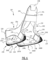
lower frame parts 6L, 6R are each covered on their underside with a resilient and/or damping material, for instance a soft plastic or natural or synthetic rubber. This resilient and/or damping material is here arranged on thelower frame parts 6L, 6R in the form of shapedparts 21 which extend from the frontouter end outer end lower frame part 6L, 6R. In the shown example the shaped parts even extend from the fronttransverse frame part 9 to the reartransverse frame part 10. - These shaped
parts 21 can be connected releasably to thelower frame parts 6L, 6R so that they can be replaced in the case of wear. For this purpose eachshaped part 21 can for instance be provided with a number of fastening elements, for instance upward directed protrusions 42 (Fig. 11 ), which can be inserted into openings in the underside of thecorresponding frame parts 6L, 6R. In this embodiment the shapedparts 21 partially enclose thecorresponding frame parts 6L, 6R so that a strong connection is formed. For this purpose eachshaped part 21 comprises here abody 40 in which on the upper side arecess 41 is formed, the cross-section of which corresponds to that of thecorresponding frame part 6L, 6R. - On the other hand, it is possible to connect shaped
parts 21 to thelower frame parts 6L, 6R permanently, for instance by glueing. An adhesive connection can optionally be combined with a mechanical connection, for instance by means of the above stated protrusions or by screws which are fastened through the shaped parts and in openings inlower frame parts 6L, 6R. - Each
shaped part 21 is further provided on its underside with a profile in order to prevent shifting of seat 1 during the reciprocal movement. In the shown example the profile comprises a series of parallelrectangular blocks 25 which are separated from each other bygrooves 26. - In this example shaped
parts 21 have a substantially constant cross-sectional form over their whole length, and can thus for instance be manufactured by extrusion. Although eachshaped part 21 is here a whole extending over the length of thecorresponding frame part 6L, 6R, it is also possible to envisage eachshaped part 21 being constructed from a number of segments which are placed contiguously one behind the other. A front and rear segment can here be used, the curvature of which is adapted to that of the front andrear ends 7, 8 of the lower frame part 6. One or more substantially straight middle segments can be placed therebetween in order to achieve the desired length. - In another example of the
seat 101 according to the invention the frame 102 is provided not with one but with two pairs of points ofattachment lower frame parts Fig. 4 ). In thisexample cloth 103 is provided with two pairs of tensioningmembers attachment ends - In fan embodiment of the
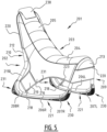
seat 201 according to the invention (Fig. 5-7 ) thecloth 203 is provided, as in the first example, with two tensioningmembers 216 which in turn are attached to points ofattachment 218 close to the rear outer ends 208L, 208R of thelower frame parts members 216 are not connected to each other but, as in the second embodiment, their free outer ends 223 are folded over and fastened to themselves. - In order to maintain sufficient tension on the folded-over
end parts cloth 203 the front and reartransverse frame parts transverse rod 235 is arranged between the legs of the reverse U-shaped front frame part 209 (Fig. 8 ). Atransverse rod 236 is here further arranged between the legs of the reverse U-shapedrear frame part 210, which rod co-acts with a strengtheningprofile 237 which is folded over the upper side of the reartransverse frame part 210. Strengtheningprofile 237 further serves as carrier for aheadrest 238 which is arranged on the upper side ofbackrest 205. - In the shown embodiment the
cloth 203 is further provided on either side withpockets 219 for receiving a mobile phone of a player, whilecloth 203 has on bothfront side 213 and rear side 214 apocket 220 for receiving a control unit for a video game. - In this embodiment it can be clearly seen that
respective stop members lower frame parts members seat 201 from falling over. For this purpose eachstop member relevant frame part 206, whereby the spaces under the upward curved front and rear outer ends 207, 208 oflower frame part 206 are as it were filled in. - Each
stop member frame part 206, and which progressively decreases from the centre of theframe part 206 towards the front and rear outer ends 207, 208, respectively. In this way a gradually increasing resistance to further deformation, and thereby to further rocking motion is formed. - In this embodiment stop
members shaped part 221 of resilient and/or damping material, and are themselves also resiliently deformable. For this purpose eachstop member chambers 239. - In the shown embodiment each
stop member lower band 232 which is connected by means of a number of resiliently flexible spacers orlamella 233 to a strip orupper band 234 mounted onlower frame part 206. Spacers orlamella 233, these definingchambers 239 therebetween, have different lengths or heights so that the distance between lower andupper band lower frame part 206. In order to increase the flexibility of the spacers orlamella 233 they take a bent or curved form here. Eachstop outer end - The presence of the
chambers 239 weakens thestop member chambers 239 being filled with a material other than the material of thestop member chambers 239 form a less serious weakening, or conversely a stiffening, when the other material is stiffer. - When
seat 201 pivots forward or rearward under the influence of a movement of a user, for instance a player of video games, the spacers orlamella 233 are deformed in succession, whereby the movement is braked and damped. The flexiblelower band 232 will here deform (shown withbroken lines 230', 231' inFig. 9 and Fig. 10 ), wherein its outermost point of contact with the ground surface shifts increasingly further in order to prevent inadvertent tipping over ofseat 201. - Although the invention has been elucidated above on the basis of a number of embodiments, it will be apparent that it is not limited thereto but can be varied in many ways. The shaped part of resilient and/or damping material, which was described above in connection to a specific seat with a closed tubular frame and a cloth tensioned thereover, could thus also be applied in combination with a conventional rocking chair with a fixed seat surface and backrest, and with legs which are positioned on the curved lower frame parts. The same also applies to the stop members, which can likewise be useful in a conventional rocking chair. Materials other than those described above can further be applied, and the different components can be embodied in different ways. Instead of upper and lower bands with lamella placed therebetween, the stop members with open section could also be embodied in other manner, for instance by making openings in a stop member which takes a solid form.
- The scope of the invention is therefore defined solely by the following claims.
Claims (15)
- Seat (1), particularly a rocking chair, comprising a frame (2), a seat surface (4) and a backrest (5), wherein the frame (2) comprises two lower frame parts (6L, 6R) extending forward from the backrest (5) and each having a curved progression which is convex in downward direction, characterized by at least one stop member (230, 231) arranged close to a front outer end (7L, 7R) and/or close to a rear outer end (8L, 8R) of each lower frame part (6L, 6R), wherein a part of the at least one stop member (230, 231) which protrudes outside the lower frame part (6L, 6R) has an open section, wherein the at least one stop member (230, 231) comprises a number of chambers (239).
- Seat (1) according to claim 1, wherein the at least one stop member (230, 231) is resiliently deformable.
- Seat (1) according to claim 1 or 2, wherein the at least one stop member (230, 231) has a variable height as seen in longitudinal direction of the relevant frame part (6L, 6R).
- Seat (1) according to any one of claims 1-3, wherein at least one of the chambers (239) is filled with a material differing from the material of the at least one stop member (230, 231).
- Seat (1) according to any one of claims 1-4, wherein the at least one stop member (230, 231) comprises an upper band (234) connected to the frame part, a number of spacers (233) protruding from the upper band (234) and defining the chambers (239) between them, and a lower band (232) connected to free ends of the spacers (233).
- Seat (1) according to claim 5, wherein at least a part of the spacers (233) is bent or curved.
- Seat (1) according to any one of the foregoing claims, wherein the at least one stop member (230, 231) is at least partially made of a resilient and/or damping material.
- Seat (1) according to any one of the foregoing claims or according to the preamble of claim 1, characterized in that the lower frame parts (6L, 6R) are each covered on an underside thereof with a resilient and/or damping material.
- Seat (1) according to claim 8, wherein the resilient and/or damping material comprises a shaped part (21) connected to the relevant frame part (6L, 6R), preferably wherein the shaped part (21) is connected releasably to the relevant frame part (6L, 6R), more preferably wherein the shaped part (21) comprises fastening elements (42) co-acting with the frame part (6L, 6R).
- Seat (1) according to claim 9, wherein the shaped part (21) extends from a position close to a front outer end (7L, 7R) of the relevant frame part (6L, 6R) to a position close to a rear outer end (8L, 8R) thereof, preferably wherein the shaped part (21) is formed integrally.
- Seat (1) according to claim 9 or 10, wherein the shaped part (21) comprises a number of segments which connect to each other in longitudinal direction of the relevant frame part (6L, 6R), preferably wherein the segments comprise, as seen in longitudinal direction of the relevant frame part (6L, 6R), a front segment, a rear segment and at least one middle segment placed therebetween.
- Seat (1) according to any one of the claims 9-11, wherein the shaped part (21) has over at least a part of its length a substantially constant cross-section.
- Seat (1) according to any one of the claims 9-12, wherein the shaped part (21) encloses the relevant frame part (6L, 6R) at least partially in cross-section, preferably wherein the shaped part (21) has on its upper side a recess (41) for receiving the relevant frame part (6L, 6R).
- Seat (1) according to any one of the claims 9-13, wherein the shaped part (21) has a profile (25, 26) on its underside.
- Seat (1) according to any one of the claims 7-14, wherein the resilient and/or damping material comprises rubber and/or wherein the resilient and/or damping material comprises a plastic.
Applications Claiming Priority (3)
| Application Number | Priority Date | Filing Date | Title |
|---|---|---|---|
| NL2023618 | 2019-08-07 | ||
| NL2023665A NL2023665B1 (en) | 2019-08-19 | 2019-08-19 | Chair, especially rocking chair |
| PCT/EP2020/072271 WO2021023868A1 (en) | 2019-08-07 | 2020-08-07 | Seat, particularly a rocking chair |
Publications (2)
| Publication Number | Publication Date |
|---|---|
| EP4009835A1 EP4009835A1 (en) | 2022-06-15 |
| EP4009835B1 true EP4009835B1 (en) | 2024-03-20 |
Family
ID=71899785
Family Applications (1)
| Application Number | Title | Priority Date | Filing Date |
|---|---|---|---|
| EP20750295.6A Active EP4009835B1 (en) | 2019-08-07 | 2020-08-07 | Seat, particularly a rocking chair |
Country Status (6)
| Country | Link |
|---|---|
| US (1) | US11805909B2 (en) |
| EP (1) | EP4009835B1 (en) |
| CN (1) | CN114466605A (en) |
| AU (1) | AU2020324557A1 (en) |
| TW (1) | TW202116228A (en) |
| WO (1) | WO2021023868A1 (en) |
Citations (2)
| Publication number | Priority date | Publication date | Assignee | Title |
|---|---|---|---|---|
| US20050275262A1 (en) * | 2004-06-10 | 2005-12-15 | Mills Robert J | Student desk chair with rockers rails |
| US20080100120A1 (en) * | 2006-10-30 | 2008-05-01 | Fletcher Scott L | Self-leveling furniture leg foot |
Family Cites Families (9)
| Publication number | Priority date | Publication date | Assignee | Title |
|---|---|---|---|---|
| US793946A (en) * | 1904-08-23 | 1905-07-04 | William G Miller | Rocker-shoe. |
| US898340A (en) * | 1908-04-06 | 1908-09-08 | J W Lanning | Cushioned rocker. |
| US1662947A (en) | 1927-02-08 | 1928-03-20 | Olin E Banker | Radio operator's chair |
| US2054487A (en) | 1935-04-19 | 1936-09-15 | Simpson William Andrew Jackson | Cushion for rails of rocking chairs |
| US3669490A (en) * | 1971-01-08 | 1972-06-13 | Doris Y Bertolet | Floor preserving shoe for platform rockers and the like |
| US5160105A (en) * | 1988-05-20 | 1992-11-03 | Nu-Zip Dee Mfg., Inc. | Protective foot device for mounting on furniture |
| US7837161B2 (en) * | 2009-01-23 | 2010-11-23 | Hiwatt Products, Llc | Furniture-foot assemblies |
| CN204580541U (en) | 2015-03-01 | 2015-08-26 | 郑文龙 | A kind of reassembling type rocking chair |
| CN106963148A (en) | 2017-04-30 | 2017-07-21 | 中山市诺可贸易有限公司 | A kind of multifunctional remotely rocking chair |
-
2020
- 2020-08-07 AU AU2020324557A patent/AU2020324557A1/en active Pending
- 2020-08-07 TW TW109126954A patent/TW202116228A/en unknown
- 2020-08-07 WO PCT/EP2020/072271 patent/WO2021023868A1/en unknown
- 2020-08-07 US US17/633,297 patent/US11805909B2/en active Active
- 2020-08-07 EP EP20750295.6A patent/EP4009835B1/en active Active
- 2020-08-07 CN CN202080069338.6A patent/CN114466605A/en active Pending
Patent Citations (2)
| Publication number | Priority date | Publication date | Assignee | Title |
|---|---|---|---|---|
| US20050275262A1 (en) * | 2004-06-10 | 2005-12-15 | Mills Robert J | Student desk chair with rockers rails |
| US20080100120A1 (en) * | 2006-10-30 | 2008-05-01 | Fletcher Scott L | Self-leveling furniture leg foot |
Also Published As
| Publication number | Publication date |
|---|---|
| WO2021023868A1 (en) | 2021-02-11 |
| US20220361675A1 (en) | 2022-11-17 |
| AU2020324557A1 (en) | 2022-03-03 |
| TW202116228A (en) | 2021-05-01 |
| US11805909B2 (en) | 2023-11-07 |
| EP4009835A1 (en) | 2022-06-15 |
| CN114466605A (en) | 2022-05-10 |
Similar Documents
| Publication | Publication Date | Title |
|---|---|---|
| JP7295177B2 (en) | posture holder | |
| JP5603329B2 (en) | Tuning backrest for seating unit | |
| US9326613B2 (en) | Upholstered seat with flexible pelvic support | |
| US8794701B2 (en) | Backrest for chair | |
| JP6640104B2 (en) | Mattress structure and method of adjusting hardness of mattress structure | |
| JP2009531082A (en) | Ergonomic side chair | |
| JP2010500148A (en) | Seat device with reclining operation | |
| WO2020044111A1 (en) | Racing gaming chair | |
| US7997651B2 (en) | Knockdown chair having reinforced side supports | |
| EP4009835B1 (en) | Seat, particularly a rocking chair | |
| US11178990B2 (en) | Pressure absorbing assembly for supporting a user above a support surface | |
| KR100761460B1 (en) | A pedestals of stand a body | |
| NL2023665B1 (en) | Chair, especially rocking chair | |
| CN109908535B (en) | Elastic rocking pad | |
| TW202110366A (en) | Seat, particularly for playing video games | |
| JP3105880U (en) | Sitting chair | |
| JP2002172039A (en) | Furniture | |
| RU2618461C2 (en) | Balancing rocker | |
| JP2006290210A (en) | Footrest for vehicle | |
| KR20230025299A (en) | Functional seat chair | |
| KR200176549Y1 (en) | A deck plank to be circular of free gymnastics the vertebrate | |
| JP2002238700A (en) | Sofa | |
| JP2019013625A (en) | Chair | |
| WO2007108753A1 (en) | Baby bouncer | |
| JP2002095545A (en) | Chair with two point support structure |
Legal Events
| Date | Code | Title | Description |
|---|---|---|---|
| STAA | Information on the status of an ep patent application or granted ep patent |
Free format text: STATUS: UNKNOWN |
|
| STAA | Information on the status of an ep patent application or granted ep patent |
Free format text: STATUS: THE INTERNATIONAL PUBLICATION HAS BEEN MADE |
|
| PUAI | Public reference made under article 153(3) epc to a published international application that has entered the european phase |
Free format text: ORIGINAL CODE: 0009012 |
|
| STAA | Information on the status of an ep patent application or granted ep patent |
Free format text: STATUS: REQUEST FOR EXAMINATION WAS MADE |
|
| 17P | Request for examination filed |
Effective date: 20220215 |
|
| AK | Designated contracting states |
Kind code of ref document: A1 Designated state(s): AL AT BE BG CH CY CZ DE DK EE ES FI FR GB GR HR HU IE IS IT LI LT LU LV MC MK MT NL NO PL PT RO RS SE SI SK SM TR |
|
| DAV | Request for validation of the european patent (deleted) | ||
| DAX | Request for extension of the european patent (deleted) | ||
| RIC1 | Information provided on ipc code assigned before grant |
Ipc: A47C 5/06 20060101ALI20230915BHEP Ipc: A47C 3/03 20060101ALI20230915BHEP Ipc: A47C 5/04 20060101ALI20230915BHEP Ipc: A47C 3/029 20060101AFI20230915BHEP |
|
| GRAP | Despatch of communication of intention to grant a patent |
Free format text: ORIGINAL CODE: EPIDOSNIGR1 |
|
| STAA | Information on the status of an ep patent application or granted ep patent |
Free format text: STATUS: GRANT OF PATENT IS INTENDED |
|
| INTG | Intention to grant announced |
Effective date: 20231103 |
|
| GRAS | Grant fee paid |
Free format text: ORIGINAL CODE: EPIDOSNIGR3 |
|
| GRAA | (expected) grant |
Free format text: ORIGINAL CODE: 0009210 |
|
| STAA | Information on the status of an ep patent application or granted ep patent |
Free format text: STATUS: THE PATENT HAS BEEN GRANTED |
|
| AK | Designated contracting states |
Kind code of ref document: B1 Designated state(s): AL AT BE BG CH CY CZ DE DK EE ES FI FR GB GR HR HU IE IS IT LI LT LU LV MC MK MT NL NO PL PT RO RS SE SI SK SM TR |
|
| REG | Reference to a national code |
Ref country code: GB Ref legal event code: FG4D |
|
| REG | Reference to a national code |
Ref country code: CH Ref legal event code: EP |
|
| REG | Reference to a national code |
Ref country code: DE Ref legal event code: R096 Ref document number: 602020027550 Country of ref document: DE |
|
| P01 | Opt-out of the competence of the unified patent court (upc) registered |
Effective date: 20240308 |