EP4009447A1 - Connecter terminal structure - Google Patents
Connecter terminal structure Download PDFInfo
- Publication number
- EP4009447A1 EP4009447A1 EP21211640.4A EP21211640A EP4009447A1 EP 4009447 A1 EP4009447 A1 EP 4009447A1 EP 21211640 A EP21211640 A EP 21211640A EP 4009447 A1 EP4009447 A1 EP 4009447A1
- Authority
- EP
- European Patent Office
- Prior art keywords
- terminal
- male
- female
- electrical contact
- spring
- Prior art date
- Legal status (The legal status is an assumption and is not a legal conclusion. Google has not performed a legal analysis and makes no representation as to the accuracy of the status listed.)
- Granted
Links
Images



Classifications
-
- H—ELECTRICITY
- H01—ELECTRIC ELEMENTS
- H01R—ELECTRICALLY-CONDUCTIVE CONNECTIONS; STRUCTURAL ASSOCIATIONS OF A PLURALITY OF MUTUALLY-INSULATED ELECTRICAL CONNECTING ELEMENTS; COUPLING DEVICES; CURRENT COLLECTORS
- H01R13/00—Details of coupling devices of the kinds covered by groups H01R12/70 or H01R24/00 - H01R33/00
- H01R13/02—Contact members
- H01R13/15—Pins, blades or sockets having separate spring member for producing or increasing contact pressure
- H01R13/17—Pins, blades or sockets having separate spring member for producing or increasing contact pressure with spring member on the pin
-
- H—ELECTRICITY
- H01—ELECTRIC ELEMENTS
- H01R—ELECTRICALLY-CONDUCTIVE CONNECTIONS; STRUCTURAL ASSOCIATIONS OF A PLURALITY OF MUTUALLY-INSULATED ELECTRICAL CONNECTING ELEMENTS; COUPLING DEVICES; CURRENT COLLECTORS
- H01R13/00—Details of coupling devices of the kinds covered by groups H01R12/70 or H01R24/00 - H01R33/00
- H01R13/02—Contact members
- H01R13/10—Sockets for co-operation with pins or blades
-
- H—ELECTRICITY
- H01—ELECTRIC ELEMENTS
- H01R—ELECTRICALLY-CONDUCTIVE CONNECTIONS; STRUCTURAL ASSOCIATIONS OF A PLURALITY OF MUTUALLY-INSULATED ELECTRICAL CONNECTING ELEMENTS; COUPLING DEVICES; CURRENT COLLECTORS
- H01R13/00—Details of coupling devices of the kinds covered by groups H01R12/70 or H01R24/00 - H01R33/00
- H01R13/02—Contact members
- H01R13/04—Pins or blades for co-operation with sockets
-
- H—ELECTRICITY
- H01—ELECTRIC ELEMENTS
- H01R—ELECTRICALLY-CONDUCTIVE CONNECTIONS; STRUCTURAL ASSOCIATIONS OF A PLURALITY OF MUTUALLY-INSULATED ELECTRICAL CONNECTING ELEMENTS; COUPLING DEVICES; CURRENT COLLECTORS
- H01R13/00—Details of coupling devices of the kinds covered by groups H01R12/70 or H01R24/00 - H01R33/00
- H01R13/02—Contact members
- H01R13/04—Pins or blades for co-operation with sockets
- H01R13/05—Resilient pins or blades
-
- H—ELECTRICITY
- H01—ELECTRIC ELEMENTS
- H01R—ELECTRICALLY-CONDUCTIVE CONNECTIONS; STRUCTURAL ASSOCIATIONS OF A PLURALITY OF MUTUALLY-INSULATED ELECTRICAL CONNECTING ELEMENTS; COUPLING DEVICES; CURRENT COLLECTORS
- H01R13/00—Details of coupling devices of the kinds covered by groups H01R12/70 or H01R24/00 - H01R33/00
- H01R13/40—Securing contact members in or to a base or case; Insulating of contact members
- H01R13/42—Securing in a demountable manner
- H01R13/422—Securing in resilient one-piece base or case, e.g. by friction; One-piece base or case formed with resilient locking means
-
- H—ELECTRICITY
- H01—ELECTRIC ELEMENTS
- H01R—ELECTRICALLY-CONDUCTIVE CONNECTIONS; STRUCTURAL ASSOCIATIONS OF A PLURALITY OF MUTUALLY-INSULATED ELECTRICAL CONNECTING ELEMENTS; COUPLING DEVICES; CURRENT COLLECTORS
- H01R13/00—Details of coupling devices of the kinds covered by groups H01R12/70 or H01R24/00 - H01R33/00
- H01R13/46—Bases; Cases
- H01R13/52—Dustproof, splashproof, drip-proof, waterproof, or flameproof cases
- H01R13/521—Sealing between contact members and housing, e.g. sealing insert
-
- H—ELECTRICITY
- H01—ELECTRIC ELEMENTS
- H01R—ELECTRICALLY-CONDUCTIVE CONNECTIONS; STRUCTURAL ASSOCIATIONS OF A PLURALITY OF MUTUALLY-INSULATED ELECTRICAL CONNECTING ELEMENTS; COUPLING DEVICES; CURRENT COLLECTORS
- H01R2103/00—Two poles
-
- H—ELECTRICITY
- H01—ELECTRIC ELEMENTS
- H01R—ELECTRICALLY-CONDUCTIVE CONNECTIONS; STRUCTURAL ASSOCIATIONS OF A PLURALITY OF MUTUALLY-INSULATED ELECTRICAL CONNECTING ELEMENTS; COUPLING DEVICES; CURRENT COLLECTORS
- H01R2201/00—Connectors or connections adapted for particular applications
- H01R2201/26—Connectors or connections adapted for particular applications for vehicles
Definitions
- the present disclosure relates to a connecter terminal structure.
- a high-voltage connecter used in an electrically powered vehicle such as an electric vehicle or a hybrid vehicle is divided into a female connecter and a male connecter.
- a male terminal and a female terminal that can be energized and inserted or removed are respectively accommodated in the male connecter and the female connecter, and the male terminal and the female terminal are electrically connected via a terminal spring. More specifically, the bar-shaped male terminal is accommodated in the male connecter. The tubular female terminal is accommodated in the female connecter. Then, the terminal spring is assembled inside the female terminal (see Patent Literature 1).
- the terminal spring to be assembled to the female terminal is held by being assembled to a holding groove formed by cutting and machining an inner wall surface of the female terminal in a circumferential direction or attaching a cover from an outside so as not to move in the female terminal or come out of the female terminal.
- Patent Literature 2 there is also proposed a contact device in which a groove is provided on an outer peripheral surface of a small diameter portion (male terminal) of a conductor along a circumferential direction, and a spring contact (annular terminal spring) obtained by a coil spring being bent in an annular shape with both end portions being joined is fitted.
- the female terminal in which the holding groove is formed as in the above Patent Literature 1 is assembled with the terminal spring, the terminal itself has a complicated shape, which makes a cutting and machining operation difficult.
- the male terminal needs to be brought into contact in displacement of the terminal spring on a female terminal side, it is necessary to perform processing with high accuracy, and like the female terminal, it is difficult to perform the cutting and machining operation.
- the holding groove of the terminal spring In a structure in which the terminal spring is assembled inside the female terminal, the holding groove of the terminal spring must be formed from a tip end of the female terminal to a rear side at a predetermined distance or more, and thus there is a problem that a length of the female terminal becomes longer by that amount.
- the present disclosure has been made in view of the above circumstances, and an object thereof is to provide a connecter terminal structure which can reduce processing cost of a terminal by simplifying a shape of a female terminal and can shorten a length of a male-female connecter in a fitting direction at the time of fitting by eliminating a holding groove of the female terminal.
- the present disclosure provides a connecter terminal structure including: a male housing of a male connecter; a male terminal accommodated in the male housing, the male terminal having a bar shape and including a first electrical contact portion; a stepped shaft portion formed at a tip end of the first electrical contact portion of the male terminal; a hood portion formed in the male housing and surrounding the first electrical contact portion; an annular terminal spring including a coil spring having conductivity and being bent in an annular shape with both end portions being joined, the annular terminal spring being externally fitted to the stepped shaft portion; an insulating cap fixed to a tip end of the stepped shaft portion and configured to hold the annular terminal spring; a female housing of a female connecter; a female terminal accommodating portion formed in the female housing and configured to be fitted into the hood portion; and a female terminal accommodated in the female terminal accommodating portion and including a second electrical contact portion, the second electrical contact portion having a tubular shape to allow the first electrical contact portion to be inserted therein.
- the processing cost of the terminal can be reduced by simplifying a shape of the female terminal and a length of the male-female connecter in the fitting direction at the time of the fitting can be shortened by eliminating the holding groove of the female terminal.
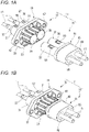
- Fig. 1A is a perspective view before fitting of a male-female connecter 11 having a connecter terminal structure according to the embodiment of the present disclosure
- Fig. 1B is a perspective view after the fitting
- Fig. 2A is an exploded perspective view of a male connecter 13
- Fig. 2B is an exploded perspective view of a female connecter 15.
- the connecter terminal structure according to the present embodiment is used for the male-female connecter 11.
- the male-female connecter 11 includes the male connecter 13 and the female connecter 15.
- the male-female connecter 11 is used, for example, in an electric vehicle.
- an inverter (not shown) that converts DC power from a battery (not shown) into AC power and supplies the AC power is connected to a three-phase AC motor (not shown).
- a high-voltage electric wire 17 with a connecter connects the battery and the inverter, the inverter and the motor, and the like.
- the male connecter 13 is attached to, for example, the inverter, and the female connecter 15 is connected to the high-voltage electric wire 17.
- the male-female connecter 11 is a high voltage two-pole type waterproof shielded connecter of a device fixed type. Although the male-female connecter 11 according to the present embodiment has a shield structure for shielding an electromagnetic wave and grounding, a description of the shield structure is omitted because the shield structure is not an essential configuration of the present disclosure.
- the male connecter 13 mainly includes a male housing 19, a male terminal 21, a stepped shaft portion 23 (see Fig. 4A ) formed on the male terminal 21, an annular terminal spring 27, and an insulating cap 29.
- the male housing 19 further includes a male housing body portion 31, a male terminal accommodating chamber 33, a fixing plate portion 35, and a hood portion 25.
- the male housing 19 forms an outer shell of the male connecter 13.
- the male housing body portion 31 is formed of a resin material having electrical insulation property.
- the male housing body portion 31 is formed by integrally connecting two cylindrical portions that have the same axial direction sharing one partition wall along a generatrix. That is, two cylindrical spaces are partitioned by the partition wall and disposed adjacent to each other in the male housing body portion 31. Each cylindrical space is opened in a front and rear in a direction along an axis.
- the "front” refers to a fitting side in each connecter
- the "rear” refers to a terminal insertion side in each connecter.
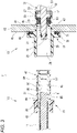
- Fig. 3 is a longitudinal cross-sectional view of the male-female connecter 11 before the fitting.
- the tubular hood portion 25 extends from a front portion of the male housing body portion 31.
- An inner side of the hood portion 25 serves as a fitting space 39 into which a female terminal accommodating portion 37 of the female connecter 15 is fitted. That is, the hood portion 25 surrounds an electrical contact portion 41 of the male terminal 21 accommodated in the male terminal accommodating chamber 33 via the fitting space 39.
- an outer periphery of a rear cylindrical space serves as a body outer peripheral portion.
- An inner side of the body outer peripheral portion serves as the male terminal accommodating chamber 33.
- the male terminal accommodating chamber 33 which is a cylindrical space, is partitioned by a disc-shaped resin wall 43.
- a concentric terminal through hole 45 is formed in the resin wall 43.
- the electrical contact portion 41 of the male terminal 21 is inserted into the terminal through hole 45.
- the male terminal 21 made of conductive metal is accommodated in the male terminal accommodating chamber 33.
- a tip end side of the male terminal 21 serves as the electrical contact portion 41 formed in a round bar shape.
- the tapered insulating cap 29 that guides the fitting with a female terminal 47 is attached to a tip end of the electrical contact portion 41.
- the insulating cap 29 is formed of a synthetic resin having the electrical insulation property, and has a finger touch prevention function in the male terminal 21.
- the male terminal 21 has an electric wire connecting portion 49 that extends rearward from the electrical contact portion 41 with the same axis and the same outer diameter as that of the electrical contact portion 41.
- a disc-shaped flange portion 51 protruding outward in a radial direction is integrally formed between the electrical contact portion 41 and the electric wire connecting portion 49.
- the flange portion 51 is loosely fitted inside the male terminal accommodating chamber 33.
- a terminal packing 53 which is an annular seal member, is externally fitted to the electrical contact portion 41 on a front side relative to the flange portion 51.
- terminal-side lip portions that are in close contact with an outer periphery of the electrical contact portion 41 are formed in multiple stages (two stages in the present embodiment) in the direction along the axis.
- accommodating chamber side lip portions that are in close contact with an inner peripheral wall of the male terminal accommodating chamber 33 are formed in multiple stages (two stages in the present embodiment) in the direction along the axis.
- the terminal packing 53 When the electrical contact portion 41 of the male terminal 21 is inserted into the terminal through hole 45 of the resin wall 43, the terminal packing 53 is sandwiched between the resin wall 43 and the flange portion 51 and is held in the male terminal accommodating chamber. Accordingly, the male connecter 13 prevents water from entering the male terminal accommodating chamber 33 from the fitting space 39.
- a flexible locking piece 57 is formed on the body outer peripheral portion of the male housing body portion 31 by a pair of parallel slits 55 (see Fig. 1A ) inserted in the direction along the axis.
- a rear end side of the body outer peripheral portion of the flexible locking piece 57 serves as a free end that is elastically displaceable toward inner and outer sides of the male terminal accommodating chamber 33.
- a locking projection 59 (see Fig. 3 ) protruding into the male terminal accommodating chamber 33 is formed at the free end.
- the flange portion 51 contacts a tapered surface 61 of the locking projection 59, and the flexible locking piece 57 is displaced to an outside of the male terminal accommodating chamber 33.
- the locking projection 59 that moves over the flange portion 51 locks a rear surface of the flange portion 51 by an elastic restoring force of the flexible locking piece 57 (a state in Fig. 3 ), and rear detachment from the male terminal accommodating chamber 33 is regulated, and the male terminal 21 is held in the male terminal accommodating chamber 33.
- the male terminal 21 is provided with a coaxial conductor connection hole (not shown) in the electric wire connecting portion 49.
- a conductor (not shown) of the high-voltage electric wire 17 routed in a device is conductively connected to the conductor connection hole by fixing such as crimping.
- the male housing 19 is attached to an attached portion 63 such as a housing of the inverter. This attachment is performed by screwing with fasteners such as bolts and nuts.
- the fixing plate portion 35 fixed to the attached portion 63 is integrally formed in the male housing 19.
- the fixing plate portion 35 protrudes outward from an outer periphery of the male housing 19 so as to face an attached surface 65 of the attached portion 63.
- the fixing plate portion 35 is formed in a rectangular plate shape in which four corners are chamfered by inclined side portions (see Figs. 1A and 1B ), for example. A shape of the fixing plate portion 35 is not limited to a rectangle.
- the fixing plate portion 35 has a plate thickness capable of obtaining a sufficient fixing strength for fixing the male housing 19 to the attached portion 63.
- a fastening hole portion 67 penetrating in a plate thickness direction is provided in the fixing plate portion 35.
- An annular packing accommodating groove 69 is formed on a surface of the fixing plate portion 35 facing the attached portion 63.
- An annular packing 71 is attached to the packing accommodating groove 69.
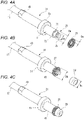
- Fig. 4 A is an exploded perspective view of the male terminal 21 before the annular terminal spring 27 is mounted
- Fig. 4B is an exploded perspective view of the male terminal 21 before the annular terminal spring 27 is mounted and the insulating cap 29 is fixed
- Fig. 4C is a perspective view of the male terminal 21 to which the insulating cap 29 is fixed.
- the stepped shaft portion 23 is formed at the tip end of the electrical contact portion 41 of the male terminal 21.
- the stepped shaft portion 23 has a stepped shape by coaxially extending a spring external fitting shaft portion 73 forward, which is a small diameter portion having a diameter smaller than that of the columnar electrical contact portion 41, on a tip end side of the electrical contact portion 41. Therefore, an outer diameter Ds of the spring external fitting shaft portion 73 is smaller than an outer diameter Dm of the electrical contact portion 41 (Ds ⁇ Dm).
- the insulating cap 29 made of an insulating resin is fixed to a tip end of the stepped shaft portion 23 to which the annular terminal spring 27 is externally fitted.
- the insulating cap 29 is fixed by, for example, a press-fitting structure provided over the spring external fitting shaft portion 73 and the insulating cap 29.
- An outer diameter Dc of the insulating cap 29 is larger than the outer diameter Ds of the spring external fitting shaft portion 73 and smaller than the outer diameter Dk of the annular terminal spring 27 (Ds ⁇ Dc ⁇ Dk). Accordingly, the annular terminal spring 27 is regulated from slipping forward from the stepped shaft portion 23 by the insulating cap 29 and is regulated from being deviated rearward by the stepped shaft portion 23, and is held by the spring external fitting shaft portion 73.
- the stepped shaft portion 23 has a cap locking shaft portion 75 coaxial with the spring external fitting shaft portion 73 and extending toward the tip end side and having a diameter smaller than that of the spring external fitting shaft portion 73.
- a cap locking groove 77 is formed on the cap locking shaft portion 75 in a circumferential direction, and a fixing claw 79 (see Fig. 3 ) provided on an inner periphery of the insulating cap 29 formed in a tubular shape is locked to the cap locking groove 77. Accordingly, the insulating cap 29 is fixed to the tip end of the stepped shaft portion 23.
- the female connecter 15 mainly includes a female housing 81 and the female terminal 47.
- An outer shell of the female connecter 15 is formed by the female housing 81 made of resin.
- the female housing 81 further includes a female housing body portion 83, a female terminal accommodating chamber 85, and the female terminal accommodating portion 37.
- the female housing body portion 83 is formed of a resin material having the electrical insulation property.
- the female housing body portion 83 has an oval cross-sectional shape orthogonal to the axis. That is, a shape the female housing body portion 83 is an elliptical columnar shape.
- a pair of parallel female terminal accommodating chambers 85 having the same direction as an axis of a columnar space are formed in the female housing body portion 83 so as to be separated from each other in a direction along a long axis of the oval.
- a pair of female terminal accommodating portions 37 extend in a front side of the female housing body portion 83 in the fitting direction.
- the female terminal accommodating portion 37 is formed such that two cylindrical portions having the same axial direction are separated from each other. Each cylindrical portion coaxially communicates with the female terminal accommodating chamber 85 positioned at a rear of the cylindrical portion. The female terminal accommodating portion 37 is inserted into each of a pair of fitting spaces 39 defined in the hood portion 25 of the male housing 19.
- the female terminal 47 made of conductive metal is accommodated in the female terminal accommodating chamber 85 and the female terminal accommodating portion 37.
- the female terminal 47 is formed in a cylindrical shape into which the electrical contact portion 41 of the male terminal 21 is coaxially inserted.
- a terminal tip end portion of the female terminal 47 is an electrical contact portion 87 into which the electrical contact portion 41 of the male terminal 21 is inserted.
- An inner diameter Df of the electrical contact portion 87 is smaller than the outer diameter Dk of the annular terminal spring 27 (Df ⁇ Dk).
- the female terminal 47 elastically deforms the annular terminal spring 27 in a reduced diameter direction, and is brought into conductive contact with the electrical contact portion 41 of the male terminal 21 with a predetermined pressing force via the annular terminal spring 27.
- the female terminal 47 has an electric wire connecting portion 88 that extends rearward from the electrical contact portion 41 with the same axis and the same outer diameter as that of the electrical contact portion 41.
- the electric wire connecting portion 88 of the female terminal 47 is provided with a coaxial conductor connection hole 89 (see Fig. 3 ).
- a conductor 91 of the high-voltage electric wire 17 routed in a vehicle is conductively connected to the conductor connection hole 89 by fixing such as crimping.
- a flexible locking piece 93 is formed in a front portion of the female terminal accommodating portion 37 by a substantially U-shaped slit 56 inserted in the direction along the axis.
- a tip end side of the flexible locking piece 93 serves as a free end that is elastically displaceable toward inner and outer sides of the female terminal accommodating chamber 85.
- a locking projection 95 (see Fig. 3 ) protruding inward is formed at the free end.
- the locking projection 95 that moves over the tip end locks a circumferential groove 97 by an elastic restoring force of the flexible locking piece 93 (a state in Fig. 5 ), and rear detachment of the female terminal 47 from the female terminal accommodating chamber 85 is regulated, and the female terminal 47 is held in the female terminal accommodating chamber 85.
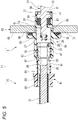
- Fig. 5 is a longitudinal cross-sectional view of the male-female connecter 11 during the fitting.
- the female terminal accommodating portion 37 of the female housing 81 is inserted into the hood portion 25 of the male housing 19.
- the female terminal accommodating portion 37 is inserted into the fitting space 39 of the hood portion 25.
- the male terminal 21 disposed coaxially with the fitting space 39 is disposed coaxially with the female terminal 47, and the electrical contact portion 41 of the male terminal 21 enters the electrical contact portion 87 of the female terminal 47 being guided by the insulating cap 29.
- Fig. 6 is a longitudinal cross-sectional view of the male-female connecter 11 after the fitting.
- the annular terminal spring 27 provided on the stepped shaft portion 23 contacts and is electrically connected to an inner periphery of the electrical contact portion 87 of the female terminal 47.
- Fig. 7 is an exploded perspective view of the male terminal 21 and the female terminal 47 before the fitting.
- a tip end of the male terminal 21 formed in the round bar shape serves as the electrical contact portion 41.
- the stepped shaft portion 23 (see Fig. 4A ) is coaxially formed at the tip end of the electrical contact portion 41.
- the stepped shaft portion 23 has the stepped shape by coaxially extending the spring external fitting shaft portion 73 having a diameter smaller than that of the columnar electrical contact portion 41 forward on the tip end side of the electrical contact portion 41.
- the insulating cap 29 made of the insulating resin is fixed to the tip end of the stepped shaft portion 23 to which the annular terminal spring 27 is externally fitted. Accordingly, the annular terminal spring 27 is regulated from slipping forward from the stepped shaft portion 23 by the insulating cap 29 and is regulated from being deviated rearward by the stepped shaft portion 23, and is held by the spring external fitting shaft portion 73.
- the female terminal 47 has the electrical contact portion 87 formed in a cylindrical shape for receiving the electrical contact portion 41 externally fitted with the annular terminal spring 27.
- the inner diameter Df of the electrical contact portion 87 in the female terminal 47 is smaller than the outer diameter Dk of the annular terminal spring 27 (Df ⁇ Dk). That is, when the electrical contact portion 41 of the male terminal 21 to which the annular terminal spring 27 is externally fitted is inserted into the female terminal 47, the electrical contact portion 41 elastically deforms the annular terminal spring 27 in the reduced diameter direction, and is brought into conductive contact with an inner peripheral surface of the female terminal 47 with a predetermined pressing force via the annular terminal spring 27.
- Fig. 8A is an exploded perspective view of a female terminal 99 according to a reference example before an annular terminal spring 113 is mounted
- Fig. 8B is a perspective view of a male terminal 101 according to the reference example and the female terminal 99 according to the reference example before the fitting
- Fig. 9 is an exploded perspective view of a male-female connecter 103 according to the reference example before the fitting.
- the male terminal 101 having a round bar-shaped electrical contact portion 107 is accommodated in a male connecter 105 of the male-female connecter 103.
- the annular terminal spring 27 is not provided in the electrical contact portion 107 of the male terminal 101.
- the cylindrical female terminal 99 is accommodated in the female terminal accommodating portion 37 of a female connecter 109.
- An annular terminal spring 113 is assembled inside an electrical contact portion 111 of the female terminal 99.
- the annular terminal spring 113 to be assembled to the female terminal 99 is assembled to a holding groove 115 formed by cutting and machining (boring) an inner wall surface of the female terminal 99 in a circumferential direction so as not to move in the female terminal 99 or come out of the female terminal 99.
- the annular terminal spring 113 mounted on an inner periphery of the female terminal 99 is eliminated, and the annular terminal spring 27 is provided on the male terminal 21, so that it is not necessary to provide the holding groove 115 on the female terminal 47. Therefore, a cutting and machining operation is remarkably facilitated, and processing cost of the female terminal 47 can be reduced.
- the stepped shaft portion 23 must be cut and machined for the electrical contact portion 41 of the male terminal 21, but it is possible to easily perform outer rounding as compared with a method of boring the holding groove 115 of the female terminal 99 in the related art. In addition, the outer rounding can achieve a higher processing accuracy than the boring.
- a length of the female terminal 47 can be shortened by that amount, and then a length of the male-female connecter 11 in the fitting direction at the time of fitting can be shortened.
- a relative positional deviation of the female terminal 47 and the male terminal 21 in a direction orthogonal to the axis is allowed in a range of (Dk - Dm)/2 (a displacement range of the annular terminal spring 27).
- the displacement range of the annular terminal spring 27 can be easily changed by design values of the outer diameter Ds of the spring external fitting shaft portion 73, which is the small diameter portion of the stepped shaft portion 23, and the average diameter Da of the coil spring.
- annular terminal spring 27 is externally fitted to the electrical contact portion 41 of the male terminal 21, a cutting and machining operation for easily changing the displacement range of the annular terminal spring 27 is easier than an operation for the holding groove 115 obtained by processing an inner peripheral surface of the female terminal 99.
- the annular terminal spring 27 can be mounted on the spring external fitting shaft portion 73 of the stepped shaft portion 23 from the front without increasing a diameter of the annular terminal spring 27. Accordingly, for example, as in the contact device disclosed in Patent Literature 2, since an operation of increasing the diameter of the spring contact (annular terminal spring 27) and then mounting the spring contact in the groove does not occur, it is possible to prevent damage or the like to the electrical contact portion 41 of the male terminal 21.
- the small diameter portion of the stepped shaft portion 23 serves as the spring external fitting shaft portion 73.
- the spring external fitting shaft portion 73 is further provided with the cap locking shaft portion 75 that extends coaxially toward the tip end side and has the diameter smaller than that of the spring external fitting shaft portion 73.
- the cap locking groove 77 is formed on the cap locking shaft portion 75 in the circumferential direction.
- the insulating cap 29 made of an insulating resin is formed in a substantially cylindrical shape.
- An inner diameter of the insulating cap 29 is set to be equal to or slightly smaller than a diameter of the cap locking shaft portion 75.
- the insulating cap 29 is formed with the fixing claw 79 that protrudes toward an inner diameter side.
- the fixing claw 79 is elastically deformed to be locked to the cap locking groove 77.
- the insulating cap 29 is fixed to the cap locking shaft portion 75. Accordingly, the annular terminal spring 27 is sandwiched between the electrical contact portion 41 and the insulating cap 29, and is fixed to the tip end of the stepped shaft portion 23.
- the annular terminal spring 27 can be held by the stepped shaft portion 23 by press-fitting and locking the insulating cap 29 to the tip end of the stepped shaft portion 23, the annular terminal spring 27 can be easily attached to the tip end of the electrical contact portion 41 without increasing the diameter of the annular terminal spring 27. Since the fixing is completed only by press-fitting the insulating cap 29 into the cap locking shaft portion 75 from the front, automation when attaching the annular terminal spring 27 to the male terminal 21 can be facilitated.
- processing cost of the terminal can be reduced by simplifying the shape of the female terminal 47 and the length of the male-female connecter 11 in the fitting direction at the time of the fitting can be shortened by eliminating the holding groove 115 of the female terminal 47.
- a connecter terminal structure includes: a male housing 19 of a male connecter 13; a male terminal 21 accommodated in the male housing 19, the male terminal 21 having a bar shape and including a first electrical contact portion (for example, an electrical contact portion 41); a stepped shaft portion 23 formed at a tip end of the first electrical contact portion of the male terminal 21; a hood portion 25 formed in the male housing 19 and surrounding the first electrical contact portion; an annular terminal spring 27 including a coil spring having conductivity and being bent in an annular shape with both end portions being joined, the annular terminal spring 27 being externally fitted to the stepped shaft portion 23; an insulating cap 29 fixed to a tip end of the stepped shaft portion 23 and configured to hold the annular terminal spring 27; a female housing 81 of a female connecter 15; a female terminal accommodating portion 37 formed in the female housing 81 and configured to be fitted into the hood portion 25; and a female terminal 47to be accommodated in the female terminal accommodating portion 37 and including a second electrical contact portion (for example,
- a terminal spring mounted on an inner periphery of the female terminal is eliminated, and the annular terminal spring is provided on the male terminal. Accordingly, since it is not necessary to provide a holding groove in the female terminal, a cutting and machining operation is remarkably facilitated, and processing cost of the female terminal can be reduced.
- the stepped shaft portion must be cut and machined in the first electrical contact portion of the male terminal, but it is possible to easily perform outer rounding as compared with a method of boring the holding groove of the female terminal in the related art. In addition, the outer rounding can achieve a higher processing accuracy than the boring.
- a length of the female terminal can be shortened by that amount, and then a length of a male-female connecter in a fitting direction at the time of fitting can be shortened.
- a relative positional deviation of the female terminal and the male terminal in a direction orthogonal to an axis is allowed in a displacement range of the annular terminal spring.
- the displacement range of the annular terminal spring can be easily changed by design values of an outer diameter of a small diameter portion of the stepped shaft portion and an average diameter of the coil spring. That is, in the connecter terminal structure, since the annular terminal spring is externally fitted to the first electrical contact portion of the male terminal, a cutting and machining operation for changing the displacement range of the annular terminal spring is easier than an operation for the holding groove obtained by processing an inner peripheral surface of the female terminal.
- the annular terminal spring can be mounted on the small diameter portion of the stepped shaft portion from a front without increasing a diameter of the annular terminal spring. Accordingly, for example, as in the contact device disclosed in Patent Literature 2, since an operation of increasing the diameter of the spring contact (annular terminal spring) and then mounting the spring contact in the groove does not occur, it is possible to prevent damage or the like to the electrical first contact portion of the male terminal.
- the stepped shaft portion 23 includes: a spring external fitting shaft portion 73 extending coaxially from the first electrical contact portion toward a tip end side and having a diameter smaller than an outer diameter of the first electrical contact portion; and a cap locking shaft portion 75 extending coaxially from the spring external fitting shaft portion 73 toward the tip end side and has a diameter smaller than that of the spring external fitting shaft portion 73.
- a cap locking groove 77 is formed on the cap locking shaft portion 75 in a circumferential direction.
- the insulating cap 29 has a tubular shape and includes a fixing claw 79 provided on an inner periphery of the insulating cap 29. The fixing claw 79 is configured to be locked to the cap locking groove 77.
- the spring external fitting shaft portion is provided with the cap locking shaft portion that extends coaxially toward the tip end side and has a diameter smaller than that of the spring external fitting shaft portion.
- the cap locking groove is formed on the cap locking shaft portion in the circumferential direction.
- An inner diameter of the insulating cap is set to be equal to or slightly smaller than a diameter the cap locking shaft portion.
- the insulating cap is formed with the fixing claw that protrudes toward an inner diameter side. When the insulating cap is press-fitted to the cap locking shaft portion from the front, the fixing claw is elastically deformed to be locked to the cap locking groove. When the fixing claw is locked to the cap locking groove, the insulating cap is fixed to the cap locking shaft portion. Accordingly, the annular terminal spring is sandwiched between the first electrical contact portion and the insulating cap, and is fixed to the tip end of the stepped shaft portion.
- the annular terminal spring can be held by the stepped shaft portion by press-fitting and locking a resin cap to the tip end of the stepped shaft portion, the annular terminal spring can be easily attached to the tip end of the first electrical contact portion without increasing the diameter of the annular terminal spring. Since the fixing is completed only by press-fitting the insulating cap into the cap locking shaft portion from the front, automation when attaching the annular terminal spring to the male terminal can be facilitated.
Landscapes
- Details Of Connecting Devices For Male And Female Coupling (AREA)
- Connector Housings Or Holding Contact Members (AREA)
Abstract
Description
- The present disclosure relates to a connecter terminal structure.
- A high-voltage connecter used in an electrically powered vehicle such as an electric vehicle or a hybrid vehicle is divided into a female connecter and a male connecter. A male terminal and a female terminal that can be energized and inserted or removed are respectively accommodated in the male connecter and the female connecter, and the male terminal and the female terminal are electrically connected via a terminal spring. More specifically, the bar-shaped male terminal is accommodated in the male connecter. The tubular female terminal is accommodated in the female connecter. Then, the terminal spring is assembled inside the female terminal (see Patent Literature 1).
- The terminal spring to be assembled to the female terminal is held by being assembled to a holding groove formed by cutting and machining an inner wall surface of the female terminal in a circumferential direction or attaching a cover from an outside so as not to move in the female terminal or come out of the female terminal.
- As disclosed in Patent Literature 2, there is also proposed a contact device in which a groove is provided on an outer peripheral surface of a small diameter portion (male terminal) of a conductor along a circumferential direction, and a spring contact (annular terminal spring) obtained by a coil spring being bent in an annular shape with both end portions being joined is fitted.
- Patent Literature 1:
JP-A-2015-028900 - Patent Literature 2:
JP-A-2008-204634 - However, since the female terminal in which the holding groove is formed as in the above Patent Literature 1 is assembled with the terminal spring, the terminal itself has a complicated shape, which makes a cutting and machining operation difficult. In addition, since the male terminal needs to be brought into contact in displacement of the terminal spring on a female terminal side, it is necessary to perform processing with high accuracy, and like the female terminal, it is difficult to perform the cutting and machining operation. In a structure in which the terminal spring is assembled inside the female terminal, the holding groove of the terminal spring must be formed from a tip end of the female terminal to a rear side at a predetermined distance or more, and thus there is a problem that a length of the female terminal becomes longer by that amount.
- As in the contact device of Patent Literature 2, when the spring contact (the annular terminal spring) is fitted into a groove provided on the outer peripheral surface of the male terminal, there is a possibility that an operation of mounting the annular terminal spring in the groove is generated after a diameter of the annular terminal spring is increased, and damage or the like to an electrical contact portion of the male terminal occurs.
- The present disclosure has been made in view of the above circumstances, and an object thereof is to provide a connecter terminal structure which can reduce processing cost of a terminal by simplifying a shape of a female terminal and can shorten a length of a male-female connecter in a fitting direction at the time of fitting by eliminating a holding groove of the female terminal.
- The present disclosure provides a connecter terminal structure including: a male housing of a male connecter; a male terminal accommodated in the male housing, the male terminal having a bar shape and including a first electrical contact portion; a stepped shaft portion formed at a tip end of the first electrical contact portion of the male terminal; a hood portion formed in the male housing and surrounding the first electrical contact portion; an annular terminal spring including a coil spring having conductivity and being bent in an annular shape with both end portions being joined, the annular terminal spring being externally fitted to the stepped shaft portion; an insulating cap fixed to a tip end of the stepped shaft portion and configured to hold the annular terminal spring; a female housing of a female connecter; a female terminal accommodating portion formed in the female housing and configured to be fitted into the hood portion; and a female terminal accommodated in the female terminal accommodating portion and including a second electrical contact portion, the second electrical contact portion having a tubular shape to allow the first electrical contact portion to be inserted therein.
- According to the connecter terminal structure of the present disclosure, the processing cost of the terminal can be reduced by simplifying a shape of the female terminal and a length of the male-female connecter in the fitting direction at the time of the fitting can be shortened by eliminating the holding groove of the female terminal.
- The present disclosure has been briefly described above. Further, details of the present disclosure will be clarified by reading an aspect (hereinafter, referred to as an "embodiment") for implementing the disclosure to be described below with reference to the accompanying drawings.
-
-
Fig. 1A is a perspective view before fitting of a male-female connecter having a connecter terminal structure according to an embodiment of the present disclosure, andFig. 1B is a perspective view after the fitting. -
Fig. 2A is an exploded perspective view of a male connecter, andFig. 2B is an exploded perspective view of a female connecter. -
Fig. 3 is a longitudinal cross-sectional view of the male-female connecter before the fitting. -
Fig. 4A is an exploded perspective view of a male terminal before an annular terminal spring is mounted,Fig. 4B is an exploded perspective view of the male terminal before the annular terminal spring is mounted and an insulating cap is fixed, andFig. 4C is a perspective view of the male terminal to which the insulating cap is fixed. -
Fig. 5 is a longitudinal cross-sectional view of the male-female connecter during the fitting. -
Fig. 6 is a longitudinal cross-sectional view of the male-female connecter after the fitting. -
Fig. 7 is an exploded perspective view of the male terminal and the female terminal before the fitting. -
Fig. 8A is an exploded perspective view of a female terminal according to a reference example before an annular terminal spring is mounted, andFig. 8B is a perspective view of a male terminal according to the reference example and the female terminal according to the reference example before the fitting. -
Fig. 9 is an exploded perspective view of a male-female connecter according to the reference example before the fitting. - Hereinafter, an embodiment according to the present disclosure will be described with reference to the drawings.
-
Fig. 1A is a perspective view before fitting of a male-female connecter 11 having a connecter terminal structure according to the embodiment of the present disclosure, andFig. 1B is a perspective view after the fitting.Fig. 2A is an exploded perspective view of amale connecter 13, andFig. 2B is an exploded perspective view of afemale connecter 15. - The connecter terminal structure according to the present embodiment is used for the male-
female connecter 11. As shown inFigs. 1A and 1B , the male-female connecter 11 includes themale connecter 13 and thefemale connecter 15. The male-female connecter 11 is used, for example, in an electric vehicle. In the electric vehicle, an inverter (not shown) that converts DC power from a battery (not shown) into AC power and supplies the AC power is connected to a three-phase AC motor (not shown). A high-voltageelectric wire 17 with a connecter connects the battery and the inverter, the inverter and the motor, and the like. In the present embodiment, themale connecter 13 is attached to, for example, the inverter, and thefemale connecter 15 is connected to the high-voltageelectric wire 17. - The male-
female connecter 11 is a high voltage two-pole type waterproof shielded connecter of a device fixed type. Although the male-female connecter 11 according to the present embodiment has a shield structure for shielding an electromagnetic wave and grounding, a description of the shield structure is omitted because the shield structure is not an essential configuration of the present disclosure. - As shown in
Figs. 1A to 2B , themale connecter 13 mainly includes amale housing 19, amale terminal 21, a stepped shaft portion 23 (seeFig. 4A ) formed on themale terminal 21, anannular terminal spring 27, and aninsulating cap 29. - The
male housing 19 further includes a malehousing body portion 31, a maleterminal accommodating chamber 33, afixing plate portion 35, and ahood portion 25. Themale housing 19 forms an outer shell of themale connecter 13. - The male
housing body portion 31 is formed of a resin material having electrical insulation property. The malehousing body portion 31 is formed by integrally connecting two cylindrical portions that have the same axial direction sharing one partition wall along a generatrix. That is, two cylindrical spaces are partitioned by the partition wall and disposed adjacent to each other in the malehousing body portion 31. Each cylindrical space is opened in a front and rear in a direction along an axis. In the present specification, the "front" refers to a fitting side in each connecter, and the "rear" refers to a terminal insertion side in each connecter. -
Fig. 3 is a longitudinal cross-sectional view of the male-female connecter 11 before the fitting. - The
tubular hood portion 25 extends from a front portion of the malehousing body portion 31. An inner side of thehood portion 25 serves as afitting space 39 into which a femaleterminal accommodating portion 37 of thefemale connecter 15 is fitted. That is, thehood portion 25 surrounds anelectrical contact portion 41 of themale terminal 21 accommodated in the maleterminal accommodating chamber 33 via thefitting space 39. In the malehousing body portion 31, an outer periphery of a rear cylindrical space serves as a body outer peripheral portion. An inner side of the body outer peripheral portion serves as the maleterminal accommodating chamber 33. - The male
terminal accommodating chamber 33, which is a cylindrical space, is partitioned by a disc-shapedresin wall 43. A concentric terminal throughhole 45 is formed in theresin wall 43. Theelectrical contact portion 41 of themale terminal 21 is inserted into the terminal throughhole 45. - The
male terminal 21 made of conductive metal is accommodated in the maleterminal accommodating chamber 33. A tip end side of themale terminal 21 serves as theelectrical contact portion 41 formed in a round bar shape. The tapered insulatingcap 29 that guides the fitting with afemale terminal 47 is attached to a tip end of theelectrical contact portion 41. The insulatingcap 29 is formed of a synthetic resin having the electrical insulation property, and has a finger touch prevention function in themale terminal 21. Themale terminal 21 has an electricwire connecting portion 49 that extends rearward from theelectrical contact portion 41 with the same axis and the same outer diameter as that of theelectrical contact portion 41. In themale terminal 21, a disc-shapedflange portion 51 protruding outward in a radial direction is integrally formed between theelectrical contact portion 41 and the electricwire connecting portion 49. Theflange portion 51 is loosely fitted inside the maleterminal accommodating chamber 33. - In the
male terminal 21, a terminal packing 53, which is an annular seal member, is externally fitted to theelectrical contact portion 41 on a front side relative to theflange portion 51. On an inner peripheral side of the terminal packing 53, terminal-side lip portions that are in close contact with an outer periphery of theelectrical contact portion 41 are formed in multiple stages (two stages in the present embodiment) in the direction along the axis. On an outer peripheral side of the terminal packing 53, accommodating chamber side lip portions that are in close contact with an inner peripheral wall of the maleterminal accommodating chamber 33 are formed in multiple stages (two stages in the present embodiment) in the direction along the axis. When theelectrical contact portion 41 of themale terminal 21 is inserted into the terminal throughhole 45 of theresin wall 43, the terminal packing 53 is sandwiched between theresin wall 43 and theflange portion 51 and is held in the male terminal accommodating chamber. Accordingly, themale connecter 13 prevents water from entering the maleterminal accommodating chamber 33 from thefitting space 39. - A
flexible locking piece 57 is formed on the body outer peripheral portion of the malehousing body portion 31 by a pair of parallel slits 55 (seeFig. 1A ) inserted in the direction along the axis. A rear end side of the body outer peripheral portion of theflexible locking piece 57 serves as a free end that is elastically displaceable toward inner and outer sides of the maleterminal accommodating chamber 33. A locking projection 59 (seeFig. 3 ) protruding into the maleterminal accommodating chamber 33 is formed at the free end. When themale terminal 21 is inserted into the maleterminal accommodating chamber 33 from a rear, in theflexible locking piece 57, theflange portion 51 contacts a taperedsurface 61 of the lockingprojection 59, and theflexible locking piece 57 is displaced to an outside of the maleterminal accommodating chamber 33. When themale terminal 21 is inserted into a predetermined position, the lockingprojection 59 that moves over theflange portion 51 locks a rear surface of theflange portion 51 by an elastic restoring force of the flexible locking piece 57 (a state inFig. 3 ), and rear detachment from the maleterminal accommodating chamber 33 is regulated, and themale terminal 21 is held in the maleterminal accommodating chamber 33. - The
male terminal 21 is provided with a coaxial conductor connection hole (not shown) in the electricwire connecting portion 49. A conductor (not shown) of the high-voltage electric wire 17 routed in a device is conductively connected to the conductor connection hole by fixing such as crimping. - The
male housing 19 is attached to an attachedportion 63 such as a housing of the inverter. This attachment is performed by screwing with fasteners such as bolts and nuts. The fixingplate portion 35 fixed to the attachedportion 63 is integrally formed in themale housing 19. The fixingplate portion 35 protrudes outward from an outer periphery of themale housing 19 so as to face an attachedsurface 65 of the attachedportion 63. The fixingplate portion 35 is formed in a rectangular plate shape in which four corners are chamfered by inclined side portions (seeFigs. 1A and 1B ), for example. A shape of the fixingplate portion 35 is not limited to a rectangle. The fixingplate portion 35 has a plate thickness capable of obtaining a sufficient fixing strength for fixing themale housing 19 to the attachedportion 63. - A
fastening hole portion 67 penetrating in a plate thickness direction is provided in the fixingplate portion 35. An annularpacking accommodating groove 69 is formed on a surface of the fixingplate portion 35 facing the attachedportion 63. Anannular packing 71 is attached to thepacking accommodating groove 69. -
Fig. 4 Ais an exploded perspective view of themale terminal 21 before theannular terminal spring 27 is mounted,Fig. 4B is an exploded perspective view of themale terminal 21 before theannular terminal spring 27 is mounted and the insulatingcap 29 is fixed, andFig. 4C is a perspective view of themale terminal 21 to which the insulatingcap 29 is fixed. - As shown in
Fig. 4A , the steppedshaft portion 23 is formed at the tip end of theelectrical contact portion 41 of themale terminal 21. The steppedshaft portion 23 has a stepped shape by coaxially extending a spring externalfitting shaft portion 73 forward, which is a small diameter portion having a diameter smaller than that of the columnarelectrical contact portion 41, on a tip end side of theelectrical contact portion 41. Therefore, an outer diameter Ds of the spring externalfitting shaft portion 73 is smaller than an outer diameter Dm of the electrical contact portion 41 (Ds < Dm). - The
annular terminal spring 27 obtained by a coil spring being bent in an annular shape with both end portions being joined is fitted (externally fitted) to an outer periphery of the spring externalfitting shaft portion 73. Therefore, an outer diameter Dk of theannular terminal spring 27 externally fitted to the steppedshaft portion 23 is an average diameter Da of the coil spring × 2 + the outer diameter Ds of the spring external fitting shaft portion (Dk = 2Da + Ds). - The insulating
cap 29 made of an insulating resin is fixed to a tip end of the steppedshaft portion 23 to which theannular terminal spring 27 is externally fitted. The insulatingcap 29 is fixed by, for example, a press-fitting structure provided over the spring externalfitting shaft portion 73 and the insulatingcap 29. An outer diameter Dc of the insulatingcap 29 is larger than the outer diameter Ds of the spring externalfitting shaft portion 73 and smaller than the outer diameter Dk of the annular terminal spring 27 (Ds < Dc < Dk). Accordingly, theannular terminal spring 27 is regulated from slipping forward from the steppedshaft portion 23 by the insulatingcap 29 and is regulated from being deviated rearward by the steppedshaft portion 23, and is held by the spring externalfitting shaft portion 73. - The stepped
shaft portion 23 has a cap lockingshaft portion 75 coaxial with the spring externalfitting shaft portion 73 and extending toward the tip end side and having a diameter smaller than that of the spring externalfitting shaft portion 73. Acap locking groove 77 is formed on the cap lockingshaft portion 75 in a circumferential direction, and a fixing claw 79 (seeFig. 3 ) provided on an inner periphery of the insulatingcap 29 formed in a tubular shape is locked to thecap locking groove 77. Accordingly, the insulatingcap 29 is fixed to the tip end of the steppedshaft portion 23. - As shown in
Figs. 1A to 2B , thefemale connecter 15 mainly includes afemale housing 81 and thefemale terminal 47. An outer shell of thefemale connecter 15 is formed by thefemale housing 81 made of resin. - The
female housing 81 further includes a femalehousing body portion 83, a femaleterminal accommodating chamber 85, and the femaleterminal accommodating portion 37. - The female
housing body portion 83 is formed of a resin material having the electrical insulation property. The femalehousing body portion 83 has an oval cross-sectional shape orthogonal to the axis. That is, a shape the femalehousing body portion 83 is an elliptical columnar shape. A pair of parallel female terminalaccommodating chambers 85 having the same direction as an axis of a columnar space are formed in the femalehousing body portion 83 so as to be separated from each other in a direction along a long axis of the oval. A pair of female terminalaccommodating portions 37 extend in a front side of the femalehousing body portion 83 in the fitting direction. - The female
terminal accommodating portion 37 is formed such that two cylindrical portions having the same axial direction are separated from each other. Each cylindrical portion coaxially communicates with the femaleterminal accommodating chamber 85 positioned at a rear of the cylindrical portion. The femaleterminal accommodating portion 37 is inserted into each of a pair offitting spaces 39 defined in thehood portion 25 of themale housing 19. - As shown in
Fig. 2B , thefemale terminal 47 made of conductive metal is accommodated in the femaleterminal accommodating chamber 85 and the femaleterminal accommodating portion 37. Thefemale terminal 47 is formed in a cylindrical shape into which theelectrical contact portion 41 of themale terminal 21 is coaxially inserted. A terminal tip end portion of thefemale terminal 47 is anelectrical contact portion 87 into which theelectrical contact portion 41 of themale terminal 21 is inserted. An inner diameter Df of theelectrical contact portion 87 is smaller than the outer diameter Dk of the annular terminal spring 27 (Df < Dk). That is, when theelectrical contact portion 41 of themale terminal 21 to which theannular terminal spring 27 is externally fitted is inserted into theelectrical contact portion 87, thefemale terminal 47 elastically deforms theannular terminal spring 27 in a reduced diameter direction, and is brought into conductive contact with theelectrical contact portion 41 of themale terminal 21 with a predetermined pressing force via theannular terminal spring 27. - The
female terminal 47 has an electricwire connecting portion 88 that extends rearward from theelectrical contact portion 41 with the same axis and the same outer diameter as that of theelectrical contact portion 41. The electricwire connecting portion 88 of thefemale terminal 47 is provided with a coaxial conductor connection hole 89 (seeFig. 3 ). Aconductor 91 of the high-voltage electric wire 17 routed in a vehicle is conductively connected to theconductor connection hole 89 by fixing such as crimping. - A
flexible locking piece 93 is formed in a front portion of the femaleterminal accommodating portion 37 by a substantiallyU-shaped slit 56 inserted in the direction along the axis. A tip end side of theflexible locking piece 93 serves as a free end that is elastically displaceable toward inner and outer sides of the femaleterminal accommodating chamber 85. A locking projection 95 (seeFig. 3 ) protruding inward is formed at the free end. When thefemale terminal 47 is inserted into the femaleterminal accommodating chamber 85 from the rear, theflexible locking piece 93 contacts a tip end of thefemale terminal 47 and is displaced to an outside of the femaleterminal accommodating chamber 85. When thefemale terminal 47 is inserted into a predetermined position, the lockingprojection 95 that moves over the tip end locks acircumferential groove 97 by an elastic restoring force of the flexible locking piece 93 (a state inFig. 5 ), and rear detachment of the female terminal 47 from the femaleterminal accommodating chamber 85 is regulated, and thefemale terminal 47 is held in the femaleterminal accommodating chamber 85. - Next, a fitting operation of the male-
female connecter 11 having the above configuration will be described. -
Fig. 5 is a longitudinal cross-sectional view of the male-female connecter 11 during the fitting. - In the male-
female connecter 11, when the fitting is started, the femaleterminal accommodating portion 37 of thefemale housing 81 is inserted into thehood portion 25 of themale housing 19. The femaleterminal accommodating portion 37 is inserted into thefitting space 39 of thehood portion 25. - When the female
terminal accommodating portion 37 is inserted into thefitting space 39, themale terminal 21 disposed coaxially with thefitting space 39 is disposed coaxially with thefemale terminal 47, and theelectrical contact portion 41 of themale terminal 21 enters theelectrical contact portion 87 of thefemale terminal 47 being guided by the insulatingcap 29. -
Fig. 6 is a longitudinal cross-sectional view of the male-female connecter 11 after the fitting. - In the
electrical contact portion 41 of themale terminal 21 that enters theelectrical contact portion 87 of thefemale terminal 47, theannular terminal spring 27 provided on the steppedshaft portion 23 contacts and is electrically connected to an inner periphery of theelectrical contact portion 87 of thefemale terminal 47. - Next, an operation of the above configuration will be described.
-
Fig. 7 is an exploded perspective view of themale terminal 21 and thefemale terminal 47 before the fitting. - In the connecter terminal structure according to the present embodiment, a tip end of the
male terminal 21 formed in the round bar shape serves as theelectrical contact portion 41. The stepped shaft portion 23 (seeFig. 4A ) is coaxially formed at the tip end of theelectrical contact portion 41. The steppedshaft portion 23 has the stepped shape by coaxially extending the spring externalfitting shaft portion 73 having a diameter smaller than that of the columnarelectrical contact portion 41 forward on the tip end side of theelectrical contact portion 41. - The insulating
cap 29 made of the insulating resin is fixed to the tip end of the steppedshaft portion 23 to which theannular terminal spring 27 is externally fitted. Accordingly, theannular terminal spring 27 is regulated from slipping forward from the steppedshaft portion 23 by the insulatingcap 29 and is regulated from being deviated rearward by the steppedshaft portion 23, and is held by the spring externalfitting shaft portion 73. - On the other hand, the
female terminal 47 has theelectrical contact portion 87 formed in a cylindrical shape for receiving theelectrical contact portion 41 externally fitted with theannular terminal spring 27. The inner diameter Df of theelectrical contact portion 87 in thefemale terminal 47 is smaller than the outer diameter Dk of the annular terminal spring 27 (Df < Dk). That is, when theelectrical contact portion 41 of themale terminal 21 to which theannular terminal spring 27 is externally fitted is inserted into thefemale terminal 47, theelectrical contact portion 41 elastically deforms theannular terminal spring 27 in the reduced diameter direction, and is brought into conductive contact with an inner peripheral surface of thefemale terminal 47 with a predetermined pressing force via theannular terminal spring 27. -
Fig. 8A is an exploded perspective view of afemale terminal 99 according to a reference example before anannular terminal spring 113 is mounted, andFig. 8B is a perspective view of amale terminal 101 according to the reference example and thefemale terminal 99 according to the reference example before the fitting.Fig. 9 is an exploded perspective view of a male-female connecter 103 according to the reference example before the fitting. - With respect to the connecter terminal structure according to the present embodiment, in a connecter terminal structure according to the reference example shown in
Figs. 8A to 9 , themale terminal 101 having a round bar-shapedelectrical contact portion 107 is accommodated in amale connecter 105 of the male-female connecter 103. Theannular terminal spring 27 is not provided in theelectrical contact portion 107 of themale terminal 101. On the other hand, the cylindricalfemale terminal 99 is accommodated in the femaleterminal accommodating portion 37 of afemale connecter 109. An annularterminal spring 113 is assembled inside anelectrical contact portion 111 of thefemale terminal 99. The annularterminal spring 113 to be assembled to thefemale terminal 99 is assembled to a holdinggroove 115 formed by cutting and machining (boring) an inner wall surface of thefemale terminal 99 in a circumferential direction so as not to move in thefemale terminal 99 or come out of thefemale terminal 99. - Therefore, in the connecter terminal structure according to the present embodiment, the annular
terminal spring 113 mounted on an inner periphery of thefemale terminal 99 is eliminated, and theannular terminal spring 27 is provided on themale terminal 21, so that it is not necessary to provide the holdinggroove 115 on thefemale terminal 47. Therefore, a cutting and machining operation is remarkably facilitated, and processing cost of thefemale terminal 47 can be reduced. The steppedshaft portion 23 must be cut and machined for theelectrical contact portion 41 of themale terminal 21, but it is possible to easily perform outer rounding as compared with a method of boring the holdinggroove 115 of thefemale terminal 99 in the related art. In addition, the outer rounding can achieve a higher processing accuracy than the boring. - Further, since it is not necessary to assemble the annular
terminal spring 113 inside thefemale terminal 47, and it is not necessary to form the holdinggroove 115 of the annularterminal spring 113 from the tip end of thefemale terminal 47 to a rear side at a predetermined distance or more, a length of thefemale terminal 47 can be shortened by that amount, and then a length of the male-female connecter 11 in the fitting direction at the time of fitting can be shortened. - Here, a relative positional deviation of the
female terminal 47 and themale terminal 21 in a direction orthogonal to the axis is allowed in a range of (Dk - Dm)/2 (a displacement range of the annular terminal spring 27). The displacement range of theannular terminal spring 27 can be easily changed by design values of the outer diameter Ds of the spring externalfitting shaft portion 73, which is the small diameter portion of the steppedshaft portion 23, and the average diameter Da of the coil spring. That is, in the connecter terminal structure according to the present embodiment, since theannular terminal spring 27 is externally fitted to theelectrical contact portion 41 of themale terminal 21, a cutting and machining operation for easily changing the displacement range of theannular terminal spring 27 is easier than an operation for the holdinggroove 115 obtained by processing an inner peripheral surface of thefemale terminal 99. - In the connecter terminal structure according to the present embodiment, the
annular terminal spring 27 can be mounted on the spring externalfitting shaft portion 73 of the steppedshaft portion 23 from the front without increasing a diameter of theannular terminal spring 27. Accordingly, for example, as in the contact device disclosed in Patent Literature 2, since an operation of increasing the diameter of the spring contact (annular terminal spring 27) and then mounting the spring contact in the groove does not occur, it is possible to prevent damage or the like to theelectrical contact portion 41 of themale terminal 21. - In the connecter terminal structure according to the present embodiment, the small diameter portion of the stepped
shaft portion 23 serves as the spring externalfitting shaft portion 73. The spring externalfitting shaft portion 73 is further provided with the cap lockingshaft portion 75 that extends coaxially toward the tip end side and has the diameter smaller than that of the spring externalfitting shaft portion 73. Thecap locking groove 77 is formed on the cap lockingshaft portion 75 in the circumferential direction. - The insulating
cap 29 made of an insulating resin is formed in a substantially cylindrical shape. An inner diameter of the insulatingcap 29 is set to be equal to or slightly smaller than a diameter of the cap lockingshaft portion 75. The insulatingcap 29 is formed with the fixingclaw 79 that protrudes toward an inner diameter side. When the insulatingcap 29 is press-fitted to the cap lockingshaft portion 75 from the front, the fixingclaw 79 is elastically deformed to be locked to thecap locking groove 77. When the fixingclaw 79 is locked to thecap locking groove 77, the insulatingcap 29 is fixed to the cap lockingshaft portion 75. Accordingly, theannular terminal spring 27 is sandwiched between theelectrical contact portion 41 and the insulatingcap 29, and is fixed to the tip end of the steppedshaft portion 23. - Therefore, in the connecter terminal structure according to the present embodiment, since the
annular terminal spring 27 can be held by the steppedshaft portion 23 by press-fitting and locking the insulatingcap 29 to the tip end of the steppedshaft portion 23, theannular terminal spring 27 can be easily attached to the tip end of theelectrical contact portion 41 without increasing the diameter of theannular terminal spring 27. Since the fixing is completed only by press-fitting the insulatingcap 29 into the cap lockingshaft portion 75 from the front, automation when attaching theannular terminal spring 27 to themale terminal 21 can be facilitated. - Therefore, according to the connecter terminal structure according to the present embodiment, processing cost of the terminal can be reduced by simplifying the shape of the
female terminal 47 and the length of the male-female connecter 11 in the fitting direction at the time of the fitting can be shortened by eliminating the holdinggroove 115 of thefemale terminal 47. - The present disclosure is not limited to the above embodiment, and modifications, improvements, and the like can be made as appropriate. In addition, materials, shapes, dimensions, numbers, arrangement positions or the like of elements in the embodiment described above are optional and not limited as long as the present disclosure can be achieved.
- As described above, a connecter terminal structure includes: a
male housing 19 of amale connecter 13; amale terminal 21 accommodated in themale housing 19, themale terminal 21 having a bar shape and including a first electrical contact portion (for example, an electrical contact portion 41); a steppedshaft portion 23 formed at a tip end of the first electrical contact portion of themale terminal 21; ahood portion 25 formed in themale housing 19 and surrounding the first electrical contact portion; anannular terminal spring 27 including a coil spring having conductivity and being bent in an annular shape with both end portions being joined, theannular terminal spring 27 being externally fitted to the steppedshaft portion 23; an insulatingcap 29 fixed to a tip end of the steppedshaft portion 23 and configured to hold theannular terminal spring 27; afemale housing 81 of afemale connecter 15; a femaleterminal accommodating portion 37 formed in thefemale housing 81 and configured to be fitted into thehood portion 25; and a female terminal 47to be accommodated in the femaleterminal accommodating portion 37 and including a second electrical contact portion (for example, an electrical contact portion 87), the second electrical contact portion having a tubular shape to allow the first electrical contact portion to be inserted therein. - According to the connecter terminal structure, a terminal spring mounted on an inner periphery of the female terminal is eliminated, and the annular terminal spring is provided on the male terminal. Accordingly, since it is not necessary to provide a holding groove in the female terminal, a cutting and machining operation is remarkably facilitated, and processing cost of the female terminal can be reduced. The stepped shaft portion must be cut and machined in the first electrical contact portion of the male terminal, but it is possible to easily perform outer rounding as compared with a method of boring the holding groove of the female terminal in the related art. In addition, the outer rounding can achieve a higher processing accuracy than the boring.
- Further, since it is not necessary to assemble the terminal spring inside the female terminal, and it is not necessary to form the holding groove of the terminal spring from a tip end of the female terminal to a rear side at a predetermined distance or more, a length of the female terminal can be shortened by that amount, and then a length of a male-female connecter in a fitting direction at the time of fitting can be shortened.
- Here, a relative positional deviation of the female terminal and the male terminal in a direction orthogonal to an axis is allowed in a displacement range of the annular terminal spring. The displacement range of the annular terminal spring can be easily changed by design values of an outer diameter of a small diameter portion of the stepped shaft portion and an average diameter of the coil spring. That is, in the connecter terminal structure, since the annular terminal spring is externally fitted to the first electrical contact portion of the male terminal, a cutting and machining operation for changing the displacement range of the annular terminal spring is easier than an operation for the holding groove obtained by processing an inner peripheral surface of the female terminal.
- In the connecter terminal structure, the annular terminal spring can be mounted on the small diameter portion of the stepped shaft portion from a front without increasing a diameter of the annular terminal spring. Accordingly, for example, as in the contact device disclosed in Patent Literature 2, since an operation of increasing the diameter of the spring contact (annular terminal spring) and then mounting the spring contact in the groove does not occur, it is possible to prevent damage or the like to the electrical first contact portion of the male terminal.
- In the connecter terminal structure, the stepped
shaft portion 23 includes: a spring externalfitting shaft portion 73 extending coaxially from the first electrical contact portion toward a tip end side and having a diameter smaller than an outer diameter of the first electrical contact portion; and a cap lockingshaft portion 75 extending coaxially from the spring externalfitting shaft portion 73 toward the tip end side and has a diameter smaller than that of the spring externalfitting shaft portion 73. Acap locking groove 77 is formed on the cap lockingshaft portion 75 in a circumferential direction. The insulatingcap 29 has a tubular shape and includes a fixingclaw 79 provided on an inner periphery of the insulatingcap 29. The fixingclaw 79 is configured to be locked to thecap locking groove 77. - According to the connecter terminal structure, the spring external fitting shaft portion is provided with the cap locking shaft portion that extends coaxially toward the tip end side and has a diameter smaller than that of the spring external fitting shaft portion. The cap locking groove is formed on the cap locking shaft portion in the circumferential direction. An inner diameter of the insulating cap is set to be equal to or slightly smaller than a diameter the cap locking shaft portion. The insulating cap is formed with the fixing claw that protrudes toward an inner diameter side. When the insulating cap is press-fitted to the cap locking shaft portion from the front, the fixing claw is elastically deformed to be locked to the cap locking groove. When the fixing claw is locked to the cap locking groove, the insulating cap is fixed to the cap locking shaft portion. Accordingly, the annular terminal spring is sandwiched between the first electrical contact portion and the insulating cap, and is fixed to the tip end of the stepped shaft portion.
- In the connecter terminal structure, since the annular terminal spring can be held by the stepped shaft portion by press-fitting and locking a resin cap to the tip end of the stepped shaft portion, the annular terminal spring can be easily attached to the tip end of the first electrical contact portion without increasing the diameter of the annular terminal spring. Since the fixing is completed only by press-fitting the insulating cap into the cap locking shaft portion from the front, automation when attaching the annular terminal spring to the male terminal can be facilitated.
Claims (2)
- A connecter terminal structure comprising:a male housing of a male connecter;a male terminal accommodated in the male housing, the male terminal having a bar shape and comprising a first electrical contact portion;a stepped shaft portion formed at a tip end of the first electrical contact portion of the male terminal;a hood portion formed in the male housing and surrounding the first electrical contact portion;an annular terminal spring comprising a coil spring having conductivity and being bent in an annular shape with both end portions being joined, the annular terminal spring being externally fitted to the stepped shaft portion;an insulating cap fixed to a tip end of the stepped shaft portion and configured to hold the annular terminal spring;a female housing of a female connecter;a female terminal accommodating portion formed in the female housing and configured to be fitted into the hood portion; anda female terminal accommodated in the female terminal accommodating portion and comprising a second electrical contact portion, the second electrical contact portion having a tubular shape to allow the first electrical contact portion to be inserted therein.
- The connecter terminal structure according to claim 1,wherein the stepped shaft portion comprises:a spring external fitting shaft portion extending coaxially from the first electrical contact portion toward a tip end side and having a diameter smaller than an outer diameter of the first electrical contact portion; anda cap locking shaft portion extending coaxially from the spring external fitting shaft portion toward the tip end side and has a diameter smaller than that of the spring external fitting shaft portion,wherein a cap locking groove is formed on the cap locking shaft portion in a circumferential direction,wherein the insulating cap has a tubular shape and comprises a fixing claw provided on an inner periphery of the insulating cap, andwherein the fixing claw is configured to be locked to the cap locking groove.
Applications Claiming Priority (1)
| Application Number | Priority Date | Filing Date | Title |
|---|---|---|---|
| JP2020200281A JP7261214B6 (en) | 2020-12-02 | 2020-12-02 | Connector terminal structure |
Publications (2)
| Publication Number | Publication Date |
|---|---|
| EP4009447A1 true EP4009447A1 (en) | 2022-06-08 |
| EP4009447B1 EP4009447B1 (en) | 2022-12-21 |
Family
ID=78820394
Family Applications (1)
| Application Number | Title | Priority Date | Filing Date |
|---|---|---|---|
| EP21211640.4A Active EP4009447B1 (en) | 2020-12-02 | 2021-12-01 | Connecter terminal structure |
Country Status (4)
| Country | Link |
|---|---|
| US (1) | US11705656B2 (en) |
| EP (1) | EP4009447B1 (en) |
| JP (1) | JP7261214B6 (en) |
| CN (1) | CN114597687B (en) |
Cited By (1)
| Publication number | Priority date | Publication date | Assignee | Title |
|---|---|---|---|---|
| DE102023106414A1 (en) | 2023-03-15 | 2024-09-19 | Phoenix Contact E-Mobility Gmbh | CONTACT DEVICE, METHOD FOR ESTABLISHING A CONNECTION BETWEEN A CONTACT DEVICE AND A PROTECTIVE DEVICE, PROTECTIVE DEVICE FOR A CONTACT DEVICE AND ARRANGEMENT COMPRISING A CONTACT DEVICE AND A PROTECTIVE DEVICE |
Families Citing this family (2)
| Publication number | Priority date | Publication date | Assignee | Title |
|---|---|---|---|---|
| JP2024017405A (en) * | 2022-07-27 | 2024-02-08 | 矢崎総業株式会社 | connector unit |
| JP7806131B2 (en) * | 2023-06-09 | 2026-01-26 | ティーイー コネクティビティ インディア プライベート リミテッド | Touch protection sleeve for HV header |
Citations (7)
| Publication number | Priority date | Publication date | Assignee | Title |
|---|---|---|---|---|
| EP0849835A2 (en) * | 1996-12-20 | 1998-06-24 | Deltron Components Limited | Electrical connectors and connecting parts therefor |
| US6336821B1 (en) * | 1999-05-26 | 2002-01-08 | Kitani Electric Co., Ltd. | Connector for use in solar generator |
| US20060127170A1 (en) * | 2003-02-18 | 2006-06-15 | Pete Balsells | Spring holding connectors |
| JP2008204634A (en) | 2007-02-16 | 2008-09-04 | Mitsubishi Electric Corp | Contact device |
| US20130045630A1 (en) * | 2011-08-19 | 2013-02-21 | Lear Corporation | Touch proof end cap for a leading end of a conducting connector |
| JP2015028900A (en) | 2013-07-05 | 2015-02-12 | 矢崎総業株式会社 | Female terminal assembly |
| EP3641068A1 (en) * | 2018-10-16 | 2020-04-22 | ODU GmbH & Co KG. | Connecting plug and socket with lamella basket |
Family Cites Families (4)
| Publication number | Priority date | Publication date | Assignee | Title |
|---|---|---|---|---|
| CN201181648Y (en) * | 2008-04-02 | 2009-01-14 | 江苏省如高高压电器有限公司 | helical spring contact |
| US9293849B2 (en) * | 2008-07-30 | 2016-03-22 | Bal Seal Engineering, Inc. | Electrical connector using a canted coil multi-metallic wire |
| CN110416784A (en) * | 2018-04-28 | 2019-11-05 | 比亚迪股份有限公司 | Electrical connector and vehicle having the same |
| CN209233051U (en) * | 2019-02-21 | 2019-08-09 | 上海杰世腾连接器有限公司 | High-voltage great-current connector containing shielding waterproof |
-
2020
- 2020-12-02 JP JP2020200281A patent/JP7261214B6/en active Active
-
2021
- 2021-11-30 US US17/539,087 patent/US11705656B2/en active Active
- 2021-12-01 EP EP21211640.4A patent/EP4009447B1/en active Active
- 2021-12-01 CN CN202111454002.4A patent/CN114597687B/en active Active
Patent Citations (7)
| Publication number | Priority date | Publication date | Assignee | Title |
|---|---|---|---|---|
| EP0849835A2 (en) * | 1996-12-20 | 1998-06-24 | Deltron Components Limited | Electrical connectors and connecting parts therefor |
| US6336821B1 (en) * | 1999-05-26 | 2002-01-08 | Kitani Electric Co., Ltd. | Connector for use in solar generator |
| US20060127170A1 (en) * | 2003-02-18 | 2006-06-15 | Pete Balsells | Spring holding connectors |
| JP2008204634A (en) | 2007-02-16 | 2008-09-04 | Mitsubishi Electric Corp | Contact device |
| US20130045630A1 (en) * | 2011-08-19 | 2013-02-21 | Lear Corporation | Touch proof end cap for a leading end of a conducting connector |
| JP2015028900A (en) | 2013-07-05 | 2015-02-12 | 矢崎総業株式会社 | Female terminal assembly |
| EP3641068A1 (en) * | 2018-10-16 | 2020-04-22 | ODU GmbH & Co KG. | Connecting plug and socket with lamella basket |
Cited By (1)
| Publication number | Priority date | Publication date | Assignee | Title |
|---|---|---|---|---|
| DE102023106414A1 (en) | 2023-03-15 | 2024-09-19 | Phoenix Contact E-Mobility Gmbh | CONTACT DEVICE, METHOD FOR ESTABLISHING A CONNECTION BETWEEN A CONTACT DEVICE AND A PROTECTIVE DEVICE, PROTECTIVE DEVICE FOR A CONTACT DEVICE AND ARRANGEMENT COMPRISING A CONTACT DEVICE AND A PROTECTIVE DEVICE |
Also Published As
| Publication number | Publication date |
|---|---|
| JP2022088050A (en) | 2022-06-14 |
| JP7261214B2 (en) | 2023-04-19 |
| EP4009447B1 (en) | 2022-12-21 |
| CN114597687A (en) | 2022-06-07 |
| CN114597687B (en) | 2024-03-19 |
| JP7261214B6 (en) | 2023-05-10 |
| US20220173541A1 (en) | 2022-06-02 |
| US11705656B2 (en) | 2023-07-18 |
Similar Documents
| Publication | Publication Date | Title |
|---|---|---|
| EP4009447B1 (en) | Connecter terminal structure | |
| US10559919B2 (en) | Connector having elastically deformable pressing protrusions | |
| EP2728678B1 (en) | Shielded wire fixing structure | |
| US10720736B2 (en) | Connector and electric wire with connector | |
| US10418743B2 (en) | Connector and electric wire with connector | |
| US11646522B2 (en) | Male connector and connector device | |
| US6821160B2 (en) | High voltage electrical connection | |
| JP7082155B2 (en) | Connector with cap | |
| EP1830438A2 (en) | Shielded electrical connector and connection system | |
| CN103718387B (en) | Adapter | |
| US20210296796A1 (en) | Electrical connector assembly | |
| CN112217017B (en) | Connector with a locking member | |
| WO2013046668A1 (en) | Shield connector and method of assembling shield connector | |
| CN115603123B (en) | Shielded connector | |
| JPH08250218A (en) | Shield wire sheath displacement prevention structure | |
| WO2014181693A1 (en) | Retaining structure for terminal fitting | |
| US20250174942A1 (en) | Connector Core Assembly, Connector and Connector Assembly | |
| CN115706367A (en) | Connector connection structure | |
| JP2023061221A (en) | connector | |
| EP4668501A1 (en) | Connector | |
| JP2022088049A (en) | Fixed structure of seal member | |
| EP4475350A1 (en) | Touch protection sleeve for an hv header | |
| JP2023065167A (en) | shield structure | |
| JP2000100524A (en) | Shield connector | |
| JP2025078361A (en) | Shielded Connectors |
Legal Events
| Date | Code | Title | Description |
|---|---|---|---|
| PUAI | Public reference made under article 153(3) epc to a published international application that has entered the european phase |
Free format text: ORIGINAL CODE: 0009012 |
|
| STAA | Information on the status of an ep patent application or granted ep patent |
Free format text: STATUS: REQUEST FOR EXAMINATION WAS MADE |
|
| 17P | Request for examination filed |
Effective date: 20211201 |
|
| AK | Designated contracting states |
Kind code of ref document: A1 Designated state(s): AL AT BE BG CH CY CZ DE DK EE ES FI FR GB GR HR HU IE IS IT LI LT LU LV MC MK MT NL NO PL PT RO RS SE SI SK SM TR |
|
| GRAP | Despatch of communication of intention to grant a patent |
Free format text: ORIGINAL CODE: EPIDOSNIGR1 |
|
| STAA | Information on the status of an ep patent application or granted ep patent |
Free format text: STATUS: GRANT OF PATENT IS INTENDED |
|
| RIC1 | Information provided on ipc code assigned before grant |
Ipc: H01R 103/00 20060101ALN20220902BHEP Ipc: H01R 13/52 20060101ALN20220902BHEP Ipc: H01R 13/17 20060101AFI20220902BHEP |
|
| INTG | Intention to grant announced |
Effective date: 20220928 |
|
| GRAS | Grant fee paid |
Free format text: ORIGINAL CODE: EPIDOSNIGR3 |
|
| GRAA | (expected) grant |
Free format text: ORIGINAL CODE: 0009210 |
|
| STAA | Information on the status of an ep patent application or granted ep patent |
Free format text: STATUS: THE PATENT HAS BEEN GRANTED |
|
| AK | Designated contracting states |
Kind code of ref document: B1 Designated state(s): AL AT BE BG CH CY CZ DE DK EE ES FI FR GB GR HR HU IE IS IT LI LT LU LV MC MK MT NL NO PL PT RO RS SE SI SK SM TR |
|
| REG | Reference to a national code |
Ref country code: GB Ref legal event code: FG4D |
|
| REG | Reference to a national code |
Ref country code: CH Ref legal event code: EP |
|
| REG | Reference to a national code |
Ref country code: DE Ref legal event code: R096 Ref document number: 602021001037 Country of ref document: DE |
|
| REG | Reference to a national code |
Ref country code: AT Ref legal event code: REF Ref document number: 1539604 Country of ref document: AT Kind code of ref document: T Effective date: 20230115 |
|
| REG | Reference to a national code |
Ref country code: IE Ref legal event code: FG4D |
|
| REG | Reference to a national code |
Ref country code: LT Ref legal event code: MG9D |
|
| REG | Reference to a national code |
Ref country code: NL Ref legal event code: MP Effective date: 20221221 |
|
| PG25 | Lapsed in a contracting state [announced via postgrant information from national office to epo] |
Ref country code: SE Free format text: LAPSE BECAUSE OF FAILURE TO SUBMIT A TRANSLATION OF THE DESCRIPTION OR TO PAY THE FEE WITHIN THE PRESCRIBED TIME-LIMIT Effective date: 20221221 Ref country code: NO Free format text: LAPSE BECAUSE OF FAILURE TO SUBMIT A TRANSLATION OF THE DESCRIPTION OR TO PAY THE FEE WITHIN THE PRESCRIBED TIME-LIMIT Effective date: 20230321 Ref country code: LT Free format text: LAPSE BECAUSE OF FAILURE TO SUBMIT A TRANSLATION OF THE DESCRIPTION OR TO PAY THE FEE WITHIN THE PRESCRIBED TIME-LIMIT Effective date: 20221221 Ref country code: FI Free format text: LAPSE BECAUSE OF FAILURE TO SUBMIT A TRANSLATION OF THE DESCRIPTION OR TO PAY THE FEE WITHIN THE PRESCRIBED TIME-LIMIT Effective date: 20221221 |
|
| REG | Reference to a national code |
Ref country code: AT Ref legal event code: MK05 Ref document number: 1539604 Country of ref document: AT Kind code of ref document: T Effective date: 20221221 |
|
| PG25 | Lapsed in a contracting state [announced via postgrant information from national office to epo] |
Ref country code: RS Free format text: LAPSE BECAUSE OF FAILURE TO SUBMIT A TRANSLATION OF THE DESCRIPTION OR TO PAY THE FEE WITHIN THE PRESCRIBED TIME-LIMIT Effective date: 20221221 Ref country code: LV Free format text: LAPSE BECAUSE OF FAILURE TO SUBMIT A TRANSLATION OF THE DESCRIPTION OR TO PAY THE FEE WITHIN THE PRESCRIBED TIME-LIMIT Effective date: 20221221 Ref country code: HR Free format text: LAPSE BECAUSE OF FAILURE TO SUBMIT A TRANSLATION OF THE DESCRIPTION OR TO PAY THE FEE WITHIN THE PRESCRIBED TIME-LIMIT Effective date: 20221221 Ref country code: GR Free format text: LAPSE BECAUSE OF FAILURE TO SUBMIT A TRANSLATION OF THE DESCRIPTION OR TO PAY THE FEE WITHIN THE PRESCRIBED TIME-LIMIT Effective date: 20230322 |
|
| PG25 | Lapsed in a contracting state [announced via postgrant information from national office to epo] |
Ref country code: NL Free format text: LAPSE BECAUSE OF FAILURE TO SUBMIT A TRANSLATION OF THE DESCRIPTION OR TO PAY THE FEE WITHIN THE PRESCRIBED TIME-LIMIT Effective date: 20221221 |
|
| PG25 | Lapsed in a contracting state [announced via postgrant information from national office to epo] |
Ref country code: SM Free format text: LAPSE BECAUSE OF FAILURE TO SUBMIT A TRANSLATION OF THE DESCRIPTION OR TO PAY THE FEE WITHIN THE PRESCRIBED TIME-LIMIT Effective date: 20221221 Ref country code: RO Free format text: LAPSE BECAUSE OF FAILURE TO SUBMIT A TRANSLATION OF THE DESCRIPTION OR TO PAY THE FEE WITHIN THE PRESCRIBED TIME-LIMIT Effective date: 20221221 Ref country code: PT Free format text: LAPSE BECAUSE OF FAILURE TO SUBMIT A TRANSLATION OF THE DESCRIPTION OR TO PAY THE FEE WITHIN THE PRESCRIBED TIME-LIMIT Effective date: 20230421 Ref country code: ES Free format text: LAPSE BECAUSE OF FAILURE TO SUBMIT A TRANSLATION OF THE DESCRIPTION OR TO PAY THE FEE WITHIN THE PRESCRIBED TIME-LIMIT Effective date: 20221221 Ref country code: EE Free format text: LAPSE BECAUSE OF FAILURE TO SUBMIT A TRANSLATION OF THE DESCRIPTION OR TO PAY THE FEE WITHIN THE PRESCRIBED TIME-LIMIT Effective date: 20221221 Ref country code: CZ Free format text: LAPSE BECAUSE OF FAILURE TO SUBMIT A TRANSLATION OF THE DESCRIPTION OR TO PAY THE FEE WITHIN THE PRESCRIBED TIME-LIMIT Effective date: 20221221 Ref country code: AT Free format text: LAPSE BECAUSE OF FAILURE TO SUBMIT A TRANSLATION OF THE DESCRIPTION OR TO PAY THE FEE WITHIN THE PRESCRIBED TIME-LIMIT Effective date: 20221221 |
|
| PG25 | Lapsed in a contracting state [announced via postgrant information from national office to epo] |
Ref country code: SK Free format text: LAPSE BECAUSE OF FAILURE TO SUBMIT A TRANSLATION OF THE DESCRIPTION OR TO PAY THE FEE WITHIN THE PRESCRIBED TIME-LIMIT Effective date: 20221221 Ref country code: PL Free format text: LAPSE BECAUSE OF FAILURE TO SUBMIT A TRANSLATION OF THE DESCRIPTION OR TO PAY THE FEE WITHIN THE PRESCRIBED TIME-LIMIT Effective date: 20221221 Ref country code: IS Free format text: LAPSE BECAUSE OF FAILURE TO SUBMIT A TRANSLATION OF THE DESCRIPTION OR TO PAY THE FEE WITHIN THE PRESCRIBED TIME-LIMIT Effective date: 20230421 Ref country code: AL Free format text: LAPSE BECAUSE OF FAILURE TO SUBMIT A TRANSLATION OF THE DESCRIPTION OR TO PAY THE FEE WITHIN THE PRESCRIBED TIME-LIMIT Effective date: 20221221 |
|
| REG | Reference to a national code |
Ref country code: DE Ref legal event code: R097 Ref document number: 602021001037 Country of ref document: DE |
|
| PLBE | No opposition filed within time limit |
Free format text: ORIGINAL CODE: 0009261 |
|
| STAA | Information on the status of an ep patent application or granted ep patent |
Free format text: STATUS: NO OPPOSITION FILED WITHIN TIME LIMIT |
|
| PG25 | Lapsed in a contracting state [announced via postgrant information from national office to epo] |
Ref country code: DK Free format text: LAPSE BECAUSE OF FAILURE TO SUBMIT A TRANSLATION OF THE DESCRIPTION OR TO PAY THE FEE WITHIN THE PRESCRIBED TIME-LIMIT Effective date: 20221221 |
|
| 26N | No opposition filed |
Effective date: 20230922 |
|
| PG25 | Lapsed in a contracting state [announced via postgrant information from national office to epo] |
Ref country code: SI Free format text: LAPSE BECAUSE OF FAILURE TO SUBMIT A TRANSLATION OF THE DESCRIPTION OR TO PAY THE FEE WITHIN THE PRESCRIBED TIME-LIMIT Effective date: 20221221 |
|
| PG25 | Lapsed in a contracting state [announced via postgrant information from national office to epo] |
Ref country code: IT Free format text: LAPSE BECAUSE OF FAILURE TO SUBMIT A TRANSLATION OF THE DESCRIPTION OR TO PAY THE FEE WITHIN THE PRESCRIBED TIME-LIMIT Effective date: 20221221 |
|
| PG25 | Lapsed in a contracting state [announced via postgrant information from national office to epo] |
Ref country code: LU Free format text: LAPSE BECAUSE OF NON-PAYMENT OF DUE FEES Effective date: 20231201 |
|
| PG25 | Lapsed in a contracting state [announced via postgrant information from national office to epo] |
Ref country code: MC Free format text: LAPSE BECAUSE OF FAILURE TO SUBMIT A TRANSLATION OF THE DESCRIPTION OR TO PAY THE FEE WITHIN THE PRESCRIBED TIME-LIMIT Effective date: 20221221 |
|
| REG | Reference to a national code |
Ref country code: BE Ref legal event code: MM Effective date: 20231231 |
|
| PG25 | Lapsed in a contracting state [announced via postgrant information from national office to epo] |
Ref country code: MC Free format text: LAPSE BECAUSE OF FAILURE TO SUBMIT A TRANSLATION OF THE DESCRIPTION OR TO PAY THE FEE WITHIN THE PRESCRIBED TIME-LIMIT Effective date: 20221221 Ref country code: LU Free format text: LAPSE BECAUSE OF NON-PAYMENT OF DUE FEES Effective date: 20231201 |
|
| REG | Reference to a national code |
Ref country code: IE Ref legal event code: MM4A |
|
| PG25 | Lapsed in a contracting state [announced via postgrant information from national office to epo] |
Ref country code: IE Free format text: LAPSE BECAUSE OF NON-PAYMENT OF DUE FEES Effective date: 20231201 |
|
| PG25 | Lapsed in a contracting state [announced via postgrant information from national office to epo] |
Ref country code: BE Free format text: LAPSE BECAUSE OF NON-PAYMENT OF DUE FEES Effective date: 20231231 |
|
| PG25 | Lapsed in a contracting state [announced via postgrant information from national office to epo] |
Ref country code: FR Free format text: LAPSE BECAUSE OF NON-PAYMENT OF DUE FEES Effective date: 20231231 |
|
| PG25 | Lapsed in a contracting state [announced via postgrant information from national office to epo] |
Ref country code: IE Free format text: LAPSE BECAUSE OF NON-PAYMENT OF DUE FEES Effective date: 20231201 Ref country code: FR Free format text: LAPSE BECAUSE OF NON-PAYMENT OF DUE FEES Effective date: 20231231 Ref country code: BE Free format text: LAPSE BECAUSE OF NON-PAYMENT OF DUE FEES Effective date: 20231231 |
|
| PG25 | Lapsed in a contracting state [announced via postgrant information from national office to epo] |
Ref country code: BG Free format text: LAPSE BECAUSE OF FAILURE TO SUBMIT A TRANSLATION OF THE DESCRIPTION OR TO PAY THE FEE WITHIN THE PRESCRIBED TIME-LIMIT Effective date: 20221221 |
|
| PG25 | Lapsed in a contracting state [announced via postgrant information from national office to epo] |
Ref country code: BG Free format text: LAPSE BECAUSE OF FAILURE TO SUBMIT A TRANSLATION OF THE DESCRIPTION OR TO PAY THE FEE WITHIN THE PRESCRIBED TIME-LIMIT Effective date: 20221221 |
|
| PG25 | Lapsed in a contracting state [announced via postgrant information from national office to epo] |
Ref country code: CY Free format text: LAPSE BECAUSE OF FAILURE TO SUBMIT A TRANSLATION OF THE DESCRIPTION OR TO PAY THE FEE WITHIN THE PRESCRIBED TIME-LIMIT; INVALID AB INITIO Effective date: 20211201 |
|
| REG | Reference to a national code |
Ref country code: CH Ref legal event code: PL |
|
| PG25 | Lapsed in a contracting state [announced via postgrant information from national office to epo] |
Ref country code: CH Free format text: LAPSE BECAUSE OF NON-PAYMENT OF DUE FEES Effective date: 20241231 |
|
| PG25 | Lapsed in a contracting state [announced via postgrant information from national office to epo] |
Ref country code: TR Free format text: LAPSE BECAUSE OF FAILURE TO SUBMIT A TRANSLATION OF THE DESCRIPTION OR TO PAY THE FEE WITHIN THE PRESCRIBED TIME-LIMIT Effective date: 20221221 |
|
| PGFP | Annual fee paid to national office [announced via postgrant information from national office to epo] |
Ref country code: DE Payment date: 20251028 Year of fee payment: 5 |
|
| PG25 | Lapsed in a contracting state [announced via postgrant information from national office to epo] |
Ref country code: HU Free format text: LAPSE BECAUSE OF FAILURE TO SUBMIT A TRANSLATION OF THE DESCRIPTION OR TO PAY THE FEE WITHIN THE PRESCRIBED TIME-LIMIT; INVALID AB INITIO Effective date: 20211201 |