EP4009434A1 - Battery, power utilization device, and battery preparation method and apparatus - Google Patents
Battery, power utilization device, and battery preparation method and apparatus Download PDFInfo
- Publication number
- EP4009434A1 EP4009434A1 EP20827955.4A EP20827955A EP4009434A1 EP 4009434 A1 EP4009434 A1 EP 4009434A1 EP 20827955 A EP20827955 A EP 20827955A EP 4009434 A1 EP4009434 A1 EP 4009434A1
- Authority
- EP
- European Patent Office
- Prior art keywords
- fire
- region
- pressure relief
- relief mechanism
- battery
- Prior art date
- Legal status (The legal status is an assumption and is not a legal conclusion. Google has not performed a legal analysis and makes no representation as to the accuracy of the status listed.)
- Granted
Links
- 238000002360 preparation method Methods 0.000 title 1
- 230000007246 mechanism Effects 0.000 claims abstract description 242
- 230000001681 protective effect Effects 0.000 claims abstract description 136
- 238000000034 method Methods 0.000 claims abstract description 12
- 239000010410 layer Substances 0.000 claims description 51
- 239000000463 material Substances 0.000 claims description 35
- 239000011241 protective layer Substances 0.000 claims description 31
- 238000002844 melting Methods 0.000 claims description 25
- 230000008018 melting Effects 0.000 claims description 25
- 239000010445 mica Substances 0.000 claims description 6
- 229910052618 mica group Inorganic materials 0.000 claims description 6
- 239000010453 quartz Substances 0.000 claims description 6
- VYPSYNLAJGMNEJ-UHFFFAOYSA-N silicon dioxide Inorganic materials O=[Si]=O VYPSYNLAJGMNEJ-UHFFFAOYSA-N 0.000 claims description 6
- 238000004519 manufacturing process Methods 0.000 claims description 3
- 238000010586 diagram Methods 0.000 description 12
- 239000000243 solution Substances 0.000 description 10
- 238000004891 communication Methods 0.000 description 9
- 238000002955 isolation Methods 0.000 description 8
- 230000000712 assembly Effects 0.000 description 7
- 238000000429 assembly Methods 0.000 description 7
- 238000001816 cooling Methods 0.000 description 7
- 238000013461 design Methods 0.000 description 5
- 238000011161 development Methods 0.000 description 5
- 238000009434 installation Methods 0.000 description 5
- 239000007773 negative electrode material Substances 0.000 description 5
- 239000007774 positive electrode material Substances 0.000 description 5
- HBBGRARXTFLTSG-UHFFFAOYSA-N Lithium ion Chemical compound [Li+] HBBGRARXTFLTSG-UHFFFAOYSA-N 0.000 description 4
- 239000008151 electrolyte solution Substances 0.000 description 4
- 238000005516 engineering process Methods 0.000 description 4
- 230000017525 heat dissipation Effects 0.000 description 4
- 229910001416 lithium ion Inorganic materials 0.000 description 4
- LYCAIKOWRPUZTN-UHFFFAOYSA-N Ethylene glycol Chemical compound OCCO LYCAIKOWRPUZTN-UHFFFAOYSA-N 0.000 description 3
- 238000007599 discharging Methods 0.000 description 3
- 239000007789 gas Substances 0.000 description 3
- 230000009467 reduction Effects 0.000 description 3
- 230000009471 action Effects 0.000 description 2
- 238000006243 chemical reaction Methods 0.000 description 2
- 239000012809 cooling fluid Substances 0.000 description 2
- 230000000694 effects Effects 0.000 description 2
- 230000002708 enhancing effect Effects 0.000 description 2
- 239000012530 fluid Substances 0.000 description 2
- 238000010438 heat treatment Methods 0.000 description 2
- 238000009413 insulation Methods 0.000 description 2
- 239000007788 liquid Substances 0.000 description 2
- 229910021645 metal ion Inorganic materials 0.000 description 2
- VNWKTOKETHGBQD-UHFFFAOYSA-N methane Chemical compound C VNWKTOKETHGBQD-UHFFFAOYSA-N 0.000 description 2
- 229910001415 sodium ion Inorganic materials 0.000 description 2
- 239000000126 substance Substances 0.000 description 2
- 238000006467 substitution reaction Methods 0.000 description 2
- XLYOFNOQVPJJNP-UHFFFAOYSA-N water Substances O XLYOFNOQVPJJNP-UHFFFAOYSA-N 0.000 description 2
- 238000003466 welding Methods 0.000 description 2
- OKTJSMMVPCPJKN-UHFFFAOYSA-N Carbon Chemical compound [C] OKTJSMMVPCPJKN-UHFFFAOYSA-N 0.000 description 1
- RYGMFSIKBFXOCR-UHFFFAOYSA-N Copper Chemical compound [Cu] RYGMFSIKBFXOCR-UHFFFAOYSA-N 0.000 description 1
- 235000015842 Hesperis Nutrition 0.000 description 1
- 235000012633 Iberis amara Nutrition 0.000 description 1
- DGAQECJNVWCQMB-PUAWFVPOSA-M Ilexoside XXIX Chemical compound C[C@@H]1CC[C@@]2(CC[C@@]3(C(=CC[C@H]4[C@]3(CC[C@@H]5[C@@]4(CC[C@@H](C5(C)C)OS(=O)(=O)[O-])C)C)[C@@H]2[C@]1(C)O)C)C(=O)O[C@H]6[C@@H]([C@H]([C@@H]([C@H](O6)CO)O)O)O.[Na+] DGAQECJNVWCQMB-PUAWFVPOSA-M 0.000 description 1
- WHXSMMKQMYFTQS-UHFFFAOYSA-N Lithium Chemical compound [Li] WHXSMMKQMYFTQS-UHFFFAOYSA-N 0.000 description 1
- JLVVSXFLKOJNIY-UHFFFAOYSA-N Magnesium ion Chemical compound [Mg+2] JLVVSXFLKOJNIY-UHFFFAOYSA-N 0.000 description 1
- FKNQFGJONOIPTF-UHFFFAOYSA-N Sodium cation Chemical compound [Na+] FKNQFGJONOIPTF-UHFFFAOYSA-N 0.000 description 1
- IDSMHEZTLOUMLM-UHFFFAOYSA-N [Li].[O].[Co] Chemical class [Li].[O].[Co] IDSMHEZTLOUMLM-UHFFFAOYSA-N 0.000 description 1
- JDZCKJOXGCMJGS-UHFFFAOYSA-N [Li].[S] Chemical compound [Li].[S] JDZCKJOXGCMJGS-UHFFFAOYSA-N 0.000 description 1
- 239000003570 air Substances 0.000 description 1
- 229910052782 aluminium Inorganic materials 0.000 description 1
- XAGFODPZIPBFFR-UHFFFAOYSA-N aluminium Chemical compound [Al] XAGFODPZIPBFFR-UHFFFAOYSA-N 0.000 description 1
- 229910052799 carbon Inorganic materials 0.000 description 1
- 239000002826 coolant Substances 0.000 description 1
- 239000000112 cooling gas Substances 0.000 description 1
- 239000000110 cooling liquid Substances 0.000 description 1
- 229910052802 copper Inorganic materials 0.000 description 1
- 239000010949 copper Substances 0.000 description 1
- 230000001066 destructive effect Effects 0.000 description 1
- QHGJSLXSVXVKHZ-UHFFFAOYSA-N dilithium;dioxido(dioxo)manganese Chemical compound [Li+].[Li+].[O-][Mn]([O-])(=O)=O QHGJSLXSVXVKHZ-UHFFFAOYSA-N 0.000 description 1
- 239000003792 electrolyte Substances 0.000 description 1
- 238000004146 energy storage Methods 0.000 description 1
- 230000007613 environmental effect Effects 0.000 description 1
- 239000012634 fragment Substances 0.000 description 1
- 239000002737 fuel gas Substances 0.000 description 1
- 239000003292 glue Substances 0.000 description 1
- 229910052744 lithium Inorganic materials 0.000 description 1
- 229910000625 lithium cobalt oxide Inorganic materials 0.000 description 1
- GELKBWJHTRAYNV-UHFFFAOYSA-K lithium iron phosphate Chemical compound [Li+].[Fe+2].[O-]P([O-])([O-])=O GELKBWJHTRAYNV-UHFFFAOYSA-K 0.000 description 1
- 229910001425 magnesium ion Inorganic materials 0.000 description 1
- 239000000203 mixture Substances 0.000 description 1
- 238000012986 modification Methods 0.000 description 1
- 230000004048 modification Effects 0.000 description 1
- 239000003345 natural gas Substances 0.000 description 1
- 238000004806 packaging method and process Methods 0.000 description 1
- 230000008569 process Effects 0.000 description 1
- 229910052710 silicon Inorganic materials 0.000 description 1
- 239000010703 silicon Substances 0.000 description 1
- 239000011734 sodium Substances 0.000 description 1
- 238000004804 winding Methods 0.000 description 1
Images


Classifications
-
- H—ELECTRICITY
- H01—ELECTRIC ELEMENTS
- H01M—PROCESSES OR MEANS, e.g. BATTERIES, FOR THE DIRECT CONVERSION OF CHEMICAL ENERGY INTO ELECTRICAL ENERGY
- H01M10/00—Secondary cells; Manufacture thereof
- H01M10/42—Methods or arrangements for servicing or maintenance of secondary cells or secondary half-cells
-
- B—PERFORMING OPERATIONS; TRANSPORTING
- B60—VEHICLES IN GENERAL
- B60L—PROPULSION OF ELECTRICALLY-PROPELLED VEHICLES; SUPPLYING ELECTRIC POWER FOR AUXILIARY EQUIPMENT OF ELECTRICALLY-PROPELLED VEHICLES; ELECTRODYNAMIC BRAKE SYSTEMS FOR VEHICLES IN GENERAL; MAGNETIC SUSPENSION OR LEVITATION FOR VEHICLES; MONITORING OPERATING VARIABLES OF ELECTRICALLY-PROPELLED VEHICLES; ELECTRIC SAFETY DEVICES FOR ELECTRICALLY-PROPELLED VEHICLES
- B60L50/00—Electric propulsion with power supplied within the vehicle
- B60L50/50—Electric propulsion with power supplied within the vehicle using propulsion power supplied by batteries or fuel cells
- B60L50/60—Electric propulsion with power supplied within the vehicle using propulsion power supplied by batteries or fuel cells using power supplied by batteries
- B60L50/64—Constructional details of batteries specially adapted for electric vehicles
-
- A—HUMAN NECESSITIES
- A62—LIFE-SAVING; FIRE-FIGHTING
- A62C—FIRE-FIGHTING
- A62C3/00—Fire prevention, containment or extinguishing specially adapted for particular objects or places
- A62C3/07—Fire prevention, containment or extinguishing specially adapted for particular objects or places in vehicles, e.g. in road vehicles
-
- A—HUMAN NECESSITIES
- A62—LIFE-SAVING; FIRE-FIGHTING
- A62C—FIRE-FIGHTING
- A62C3/00—Fire prevention, containment or extinguishing specially adapted for particular objects or places
- A62C3/16—Fire prevention, containment or extinguishing specially adapted for particular objects or places in electrical installations, e.g. cableways
-
- A—HUMAN NECESSITIES
- A62—LIFE-SAVING; FIRE-FIGHTING
- A62C—FIRE-FIGHTING
- A62C35/00—Permanently-installed equipment
- A62C35/02—Permanently-installed equipment with containers for delivering the extinguishing substance
- A62C35/10—Containers destroyed or opened by flames or heat
-
- A—HUMAN NECESSITIES
- A62—LIFE-SAVING; FIRE-FIGHTING
- A62C—FIRE-FIGHTING
- A62C35/00—Permanently-installed equipment
- A62C35/58—Pipe-line systems
- A62C35/68—Details, e.g. of pipes or valve systems
-
- B—PERFORMING OPERATIONS; TRANSPORTING
- B60—VEHICLES IN GENERAL
- B60L—PROPULSION OF ELECTRICALLY-PROPELLED VEHICLES; SUPPLYING ELECTRIC POWER FOR AUXILIARY EQUIPMENT OF ELECTRICALLY-PROPELLED VEHICLES; ELECTRODYNAMIC BRAKE SYSTEMS FOR VEHICLES IN GENERAL; MAGNETIC SUSPENSION OR LEVITATION FOR VEHICLES; MONITORING OPERATING VARIABLES OF ELECTRICALLY-PROPELLED VEHICLES; ELECTRIC SAFETY DEVICES FOR ELECTRICALLY-PROPELLED VEHICLES
- B60L58/00—Methods or circuit arrangements for monitoring or controlling batteries or fuel cells, specially adapted for electric vehicles
- B60L58/10—Methods or circuit arrangements for monitoring or controlling batteries or fuel cells, specially adapted for electric vehicles for monitoring or controlling batteries
- B60L58/24—Methods or circuit arrangements for monitoring or controlling batteries or fuel cells, specially adapted for electric vehicles for monitoring or controlling batteries for controlling the temperature of batteries
- B60L58/26—Methods or circuit arrangements for monitoring or controlling batteries or fuel cells, specially adapted for electric vehicles for monitoring or controlling batteries for controlling the temperature of batteries by cooling
-
- B—PERFORMING OPERATIONS; TRANSPORTING
- B60—VEHICLES IN GENERAL
- B60L—PROPULSION OF ELECTRICALLY-PROPELLED VEHICLES; SUPPLYING ELECTRIC POWER FOR AUXILIARY EQUIPMENT OF ELECTRICALLY-PROPELLED VEHICLES; ELECTRODYNAMIC BRAKE SYSTEMS FOR VEHICLES IN GENERAL; MAGNETIC SUSPENSION OR LEVITATION FOR VEHICLES; MONITORING OPERATING VARIABLES OF ELECTRICALLY-PROPELLED VEHICLES; ELECTRIC SAFETY DEVICES FOR ELECTRICALLY-PROPELLED VEHICLES
- B60L58/00—Methods or circuit arrangements for monitoring or controlling batteries or fuel cells, specially adapted for electric vehicles
- B60L58/10—Methods or circuit arrangements for monitoring or controlling batteries or fuel cells, specially adapted for electric vehicles for monitoring or controlling batteries
- B60L58/24—Methods or circuit arrangements for monitoring or controlling batteries or fuel cells, specially adapted for electric vehicles for monitoring or controlling batteries for controlling the temperature of batteries
- B60L58/27—Methods or circuit arrangements for monitoring or controlling batteries or fuel cells, specially adapted for electric vehicles for monitoring or controlling batteries for controlling the temperature of batteries by heating
-
- H—ELECTRICITY
- H01—ELECTRIC ELEMENTS
- H01M—PROCESSES OR MEANS, e.g. BATTERIES, FOR THE DIRECT CONVERSION OF CHEMICAL ENERGY INTO ELECTRICAL ENERGY
- H01M10/00—Secondary cells; Manufacture thereof
-
- H—ELECTRICITY
- H01—ELECTRIC ELEMENTS
- H01M—PROCESSES OR MEANS, e.g. BATTERIES, FOR THE DIRECT CONVERSION OF CHEMICAL ENERGY INTO ELECTRICAL ENERGY
- H01M10/00—Secondary cells; Manufacture thereof
- H01M10/60—Heating or cooling; Temperature control
- H01M10/65—Means for temperature control structurally associated with the cells
- H01M10/655—Solid structures for heat exchange or heat conduction
- H01M10/6556—Solid parts with flow channel passages or pipes for heat exchange
-
- H—ELECTRICITY
- H01—ELECTRIC ELEMENTS
- H01M—PROCESSES OR MEANS, e.g. BATTERIES, FOR THE DIRECT CONVERSION OF CHEMICAL ENERGY INTO ELECTRICAL ENERGY
- H01M10/00—Secondary cells; Manufacture thereof
- H01M10/60—Heating or cooling; Temperature control
- H01M10/65—Means for temperature control structurally associated with the cells
- H01M10/656—Means for temperature control structurally associated with the cells characterised by the type of heat-exchange fluid
- H01M10/6567—Liquids
-
- H—ELECTRICITY
- H01—ELECTRIC ELEMENTS
- H01M—PROCESSES OR MEANS, e.g. BATTERIES, FOR THE DIRECT CONVERSION OF CHEMICAL ENERGY INTO ELECTRICAL ENERGY
- H01M10/00—Secondary cells; Manufacture thereof
- H01M10/60—Heating or cooling; Temperature control
- H01M10/65—Means for temperature control structurally associated with the cells
- H01M10/658—Means for temperature control structurally associated with the cells by thermal insulation or shielding
-
- H—ELECTRICITY
- H01—ELECTRIC ELEMENTS
- H01M—PROCESSES OR MEANS, e.g. BATTERIES, FOR THE DIRECT CONVERSION OF CHEMICAL ENERGY INTO ELECTRICAL ENERGY
- H01M50/00—Constructional details or processes of manufacture of the non-active parts of electrochemical cells other than fuel cells, e.g. hybrid cells
- H01M50/30—Arrangements for facilitating escape of gases
- H01M50/317—Re-sealable arrangements
-
- H—ELECTRICITY
- H01—ELECTRIC ELEMENTS
- H01M—PROCESSES OR MEANS, e.g. BATTERIES, FOR THE DIRECT CONVERSION OF CHEMICAL ENERGY INTO ELECTRICAL ENERGY
- H01M50/00—Constructional details or processes of manufacture of the non-active parts of electrochemical cells other than fuel cells, e.g. hybrid cells
- H01M50/30—Arrangements for facilitating escape of gases
- H01M50/342—Non-re-sealable arrangements
-
- H—ELECTRICITY
- H01—ELECTRIC ELEMENTS
- H01M—PROCESSES OR MEANS, e.g. BATTERIES, FOR THE DIRECT CONVERSION OF CHEMICAL ENERGY INTO ELECTRICAL ENERGY
- H01M50/00—Constructional details or processes of manufacture of the non-active parts of electrochemical cells other than fuel cells, e.g. hybrid cells
- H01M50/30—Arrangements for facilitating escape of gases
- H01M50/375—Vent means sensitive to or responsive to temperature
-
- H—ELECTRICITY
- H01—ELECTRIC ELEMENTS
- H01M—PROCESSES OR MEANS, e.g. BATTERIES, FOR THE DIRECT CONVERSION OF CHEMICAL ENERGY INTO ELECTRICAL ENERGY
- H01M50/00—Constructional details or processes of manufacture of the non-active parts of electrochemical cells other than fuel cells, e.g. hybrid cells
- H01M50/30—Arrangements for facilitating escape of gases
- H01M50/383—Flame arresting or ignition-preventing means
-
- H—ELECTRICITY
- H01—ELECTRIC ELEMENTS
- H01M—PROCESSES OR MEANS, e.g. BATTERIES, FOR THE DIRECT CONVERSION OF CHEMICAL ENERGY INTO ELECTRICAL ENERGY
- H01M50/00—Constructional details or processes of manufacture of the non-active parts of electrochemical cells other than fuel cells, e.g. hybrid cells
- H01M50/50—Current conducting connections for cells or batteries
- H01M50/572—Means for preventing undesired use or discharge
- H01M50/584—Means for preventing undesired use or discharge for preventing incorrect connections inside or outside the batteries
-
- B—PERFORMING OPERATIONS; TRANSPORTING
- B60—VEHICLES IN GENERAL
- B60L—PROPULSION OF ELECTRICALLY-PROPELLED VEHICLES; SUPPLYING ELECTRIC POWER FOR AUXILIARY EQUIPMENT OF ELECTRICALLY-PROPELLED VEHICLES; ELECTRODYNAMIC BRAKE SYSTEMS FOR VEHICLES IN GENERAL; MAGNETIC SUSPENSION OR LEVITATION FOR VEHICLES; MONITORING OPERATING VARIABLES OF ELECTRICALLY-PROPELLED VEHICLES; ELECTRIC SAFETY DEVICES FOR ELECTRICALLY-PROPELLED VEHICLES
- B60L2240/00—Control parameters of input or output; Target parameters
- B60L2240/40—Drive Train control parameters
- B60L2240/54—Drive Train control parameters related to batteries
- B60L2240/545—Temperature
-
- H—ELECTRICITY
- H01—ELECTRIC ELEMENTS
- H01M—PROCESSES OR MEANS, e.g. BATTERIES, FOR THE DIRECT CONVERSION OF CHEMICAL ENERGY INTO ELECTRICAL ENERGY
- H01M2200/00—Safety devices for primary or secondary batteries
- H01M2200/20—Pressure-sensitive devices
-
- Y—GENERAL TAGGING OF NEW TECHNOLOGICAL DEVELOPMENTS; GENERAL TAGGING OF CROSS-SECTIONAL TECHNOLOGIES SPANNING OVER SEVERAL SECTIONS OF THE IPC; TECHNICAL SUBJECTS COVERED BY FORMER USPC CROSS-REFERENCE ART COLLECTIONS [XRACs] AND DIGESTS
- Y02—TECHNOLOGIES OR APPLICATIONS FOR MITIGATION OR ADAPTATION AGAINST CLIMATE CHANGE
- Y02E—REDUCTION OF GREENHOUSE GAS [GHG] EMISSIONS, RELATED TO ENERGY GENERATION, TRANSMISSION OR DISTRIBUTION
- Y02E60/00—Enabling technologies; Technologies with a potential or indirect contribution to GHG emissions mitigation
- Y02E60/10—Energy storage using batteries
-
- Y—GENERAL TAGGING OF NEW TECHNOLOGICAL DEVELOPMENTS; GENERAL TAGGING OF CROSS-SECTIONAL TECHNOLOGIES SPANNING OVER SEVERAL SECTIONS OF THE IPC; TECHNICAL SUBJECTS COVERED BY FORMER USPC CROSS-REFERENCE ART COLLECTIONS [XRACs] AND DIGESTS
- Y02—TECHNOLOGIES OR APPLICATIONS FOR MITIGATION OR ADAPTATION AGAINST CLIMATE CHANGE
- Y02T—CLIMATE CHANGE MITIGATION TECHNOLOGIES RELATED TO TRANSPORTATION
- Y02T10/00—Road transport of goods or passengers
- Y02T10/60—Other road transportation technologies with climate change mitigation effect
- Y02T10/70—Energy storage systems for electromobility, e.g. batteries
Abstract
Description
- The present application relates to the field of energy storage devices, and in particular to a battery, a power consumption device, and a method and device for producing a battery.
- Energy saving and emission reduction are the key to the sustainable development of the automotive industry. In this case, electric vehicles have become an important part of the sustainable development of the automotive industry due to their advantages of energy saving and environmental-friendliness. For the electric vehicles, the battery technology is an important factor for their development.
- In the development of the battery technology, in addition to improving the performance of batteries, safety is also an issue that cannot be ignored. If the safety of the batteries cannot be ensured, the batteries cannot be used. Therefore, how to enhance the safety of the batteries is an urgent technical problem to be solved in the battery technology.
- The present application provides a battery, a power consumption device, and a method and device for producing a battery, which could improve the safety performance of the battery.
- In a first aspect, a battery is provided, and the battery includes: a battery cell, the battery cell including a pressure relief mechanism, the pressure relief mechanism configured to be actuated when an internal pressure or temperature of the battery cell reaches a threshold, to relieve the internal pressure or temperature; a fire-fighting pipeline configured to accommodate a fire-fighting medium, the fire-fighting pipeline including a first region corresponding to the pressure relief mechanism and a second region located at a periphery of the first region, the first region being configured to be damaged when the pressure relief mechanism is actuated, such that the fire-fighting medium is discharged, and the second region being configured to remain intact when the pressure relief mechanism is actuated, such that the fire-fighting medium is capable of flowing from the second region to the first region; and a protective component disposed between the fire-fighting pipeline and the battery cell and configured to protect the second region.
- Therefore, the battery of an embodiment of the present application may include one or more battery cells, the battery cell is provided with a pressure relief mechanism, and the pressure relief mechanism may be actuated when an internal temperature or pressure of the battery cell exceeds a threshold, to relieve the internal pressure or temperature; a fire-fighting pipeline is provided at a position corresponding to the pressure relief mechanism, and when the pressure relief mechanism is actuated, emissions discharged from the pressure relief mechanism may damage the fire-fighting pipeline, so that a fire-fighting medium accommodated in the fire-fighting pipeline flows out from a damaged position and flows to the pressure relief mechanism so as to lower a temperature of the battery cell; meanwhile, a protective component is provided between the fire-fighting pipeline and the battery cell, and the protective component may protect a second region on the fire-fighting pipeline located at a periphery of a first region corresponding to the pressure relief mechanism, so that the pressure relief mechanism only damages the first region of the fire-fighting pipeline corresponding to the pressure relief mechanism, and further, a position where the fire-fighting medium in the fire-fighting pipeline flows out is concentrated in a position corresponding to the pressure relief mechanism, in this way, the heat dissipation efficiency of the battery cell could be improved, and the fire-fighting medium in the fire-fighting pipeline could be more effectively utilized.
- In some embodiments, the protective component is disposed between the second region of the fire-fighting pipeline and the battery cell, and the protective component is configured to protect the second region when the pressure relief mechanism is actuated.
- That is, the protective component may be disposed only at the second region, for example, the second region may be wrapped by the protective component, and in this way the protective component may include a plurality of separate structures, which saves an installation space.
- In some embodiments, the protective component includes a protective zone and a weakened zone, the protective zone is configured to protect the second region of the fire-fighting pipeline when the pressure relief mechanism is actuated, the weakened zone is disposed opposite to the pressure relief mechanism, and the weakened zone is configured such that emissions from the battery cell are capable of passing through the weakened zone to damage the first region when the pressure relief mechanism is actuated.
- If the protective component is set as a plurality of separate structures, it is time-consuming to respectively install the protective components in each second region. Therefore, the protective component may be set as an integral component, and a weakened zone corresponding to the pressure relief mechanism is provided on the protective component, so that when the pressure relief mechanism is actuated, the first region may be damaged through the weakened zone and a protective zone except the weakened zone may protect the second region from being damaged.
- In some embodiments, a first recess is provided on the protective component, the fire-fighting pipeline is disposed in the first recess, and the first recess is configured to collect the fire-fighting medium used to flow into the battery cell when the pressure relief mechanism is actuated.
- A recess on the protective component may fix the fire-fighting pipeline and collect and guide the fire-fighting medium to flow into the battery cell.
- In some embodiments, the weakened zone is provided in a region on a bottom wall of the first recess corresponding to the first region.
- In some embodiments, a width of the weakened zone in a first direction is greater than or equal to a width of the bottom wall of the first recess in the first direction, and the first direction is perpendicular to an axis of the fire-fighting pipeline in the first region.
- In some embodiments, a width of the weakened zone in a first direction is greater than a diameter of the fire-fighting pipeline, and the first direction is perpendicular to an axis of the fire-fighting pipeline in the first region.
- In some embodiments, an orthographic projection of the weakened zone on a first plane covers an orthographic projection of the pressure relief mechanism on the first plane, and the first plane is parallel to a surface of a wall where the pressure relief mechanism of the battery cell is located facing toward an interior of the battery cell.
- With the foregoing arrangement, the emissions discharged when the pressure relief mechanism is actuated can quickly and effectively break through the corresponding first region.
- In some embodiments, the fire-fighting pipeline is disposed on one side of the pressure relief mechanism away from an interior of the battery cell.
- In some embodiments, the pressure relief mechanism is an axisymmetric structure, and an axis of the fire-fighting pipeline in the first region is perpendicular to and lies in a same plane as an axis of the pressure relief mechanism.
- In some embodiments, a melting point of a material of the protective component is greater than a melting point of a material of the fire-fighting pipeline.
- In some embodiments, a melting point of a material of the protective component is greater than or equal to 800°C.
- Considering that a temperature of the emissions discharged from the pressure relief mechanism is high, a material with a high melting point should be selected for the protective component.
- In some embodiments, a material of the protective component is mica or quartz.
- In some embodiments, the battery further includes: a bus component configured to implement electrical connection of a plurality of battery cells; and an insulating protective layer configured to cover the bus component to prevent emissions from the battery cell from short-circuiting the plurality of the battery cells when the pressure relief mechanism is actuated, and a thickness of the insulating protective layer is greater than 0.1 mm.
- In some embodiments, a melting point of a material of the insulating protective layer is greater than or equal to 800°C.
- In some embodiments, a material of the insulating protective layer is mica or quartz.
- In some embodiments, the battery further includes: an insulating layer disposed between the pressure relief mechanism and the protective component. In this way, insulation between the battery cells can be implemented.
- In some embodiments, the insulating layer is configured to wrap the bus component of the battery, and an insulating protective layer is provided in a region on a surface of the insulating layer corresponding to the bus component, where the bus component is configured to implement electrical connection of a plurality of battery cells, and the insulating protective layer is configured to cover the bus component to prevent emissions from the battery cell from short-circuiting the plurality of the battery cells when the pressure relief mechanism is actuated.
- In some embodiments, the protective component and the insulating protective layer are an integrally formed structure.
- In some embodiments, a second recess is provided in a region of the insulating layer corresponding to the pressure relief mechanism, and the protective component is disposed in the second recess.
- In some embodiments, a first recess on the protective component is disposed in the second recess, the fire-fighting pipeline is disposed in the first recess, and the first recess is configured to collect the fire-fighting medium used to flow into the battery cell when the pressure relief mechanism is actuated.
- With a recess provided on the insulating layer, it is convenient to install and fix the protective component and the fire-fighting pipeline, and it is easy to realize that positions of the protective component and the fire-fighting pipeline correspond to a position of the pressure relief mechanism.
- In some embodiments, a fixing member is provided in the second recess, and the fixing member is configured to fix the protective component and the fire-fighting pipeline.
- In some embodiments, a melting point of a material of the insulating layer is lower than a melting point of the protective component, and the insulating layer is melted by emissions from the battery cell when the pressure relief mechanism is actuated.
- In order to enable the emissions discharged when the pressure relief mechanism is actuated to break through the corresponding first region quickly and effectively, a material with a lower melting point should be selected as a material of the insulating layer, so that the insulating layer can be quickly melted by the emissions.
- In a second aspect, a power consumption device is provided, including the battery according to the first aspect or any one of the embodiments of the first aspect.
- In some embodiments, the power consumption device is a vehicle, a ship or a spacecraft.
- In a third aspect, a method for producing a battery is provided, including providing a battery cell, the battery cell including a pressure relief mechanism, the pressure relief mechanism configured to be actuated when an internal pressure or temperature of the battery cell reaches a threshold, to relieve the internal pressure or temperature; providing a fire-fighting pipeline, the fire-fighting pipeline being configured to accommodate a fire-fighting medium, the fire-fighting pipeline including a first region corresponding to the pressure relief mechanism and a second region located at a periphery of the first region, the first region being configured to be damaged when the pressure relief mechanism is actuated, such that the fire-fighting medium is discharged, and the second region being configured to remain intact when the pressure relief mechanism is actuated, such that the fire-fighting medium is capable of flowing from the second region to the first region; and providing a protective component, the protective component being disposed between the fire-fighting pipeline and the battery cell, and the protective component being configured to protect the second region.
- In some embodiments, the protective component is disposed between the second region of the fire-fighting pipeline and the battery cell, and the protective component is configured to protect the second region when the pressure relief mechanism is actuated.
- In some embodiments, the protective component includes a protective zone and a weakened zone, the protective zone is configured to protect the second region of the fire-fighting pipeline when the pressure relief mechanism is actuated, the weakened zone is disposed opposite to the pressure relief mechanism, and the weakened zone is configured such that emissions from the battery cell are capable of passing through the weakened zone to damage the first region when the pressure relief mechanism is actuated.
- In some embodiments, a first recess is provided on the protective component, the fire-fighting pipeline is disposed in the first recess, and the first recess is configured to collect the fire-fighting medium used to flow into the battery cell when the pressure relief mechanism is actuated.
- In a fourth aspect, a device for producing a battery is provided, including a module for executing the method provided in the foregoing third aspect.
-
-
FIG. 1 is a schematic diagram of a vehicle according to an embodiment of the present application; -
FIG. 2 is a schematic structural diagram of a battery according to an embodiment of the present application; -
FIG. 3 is a structural schematic diagram of a battery module according to an embodiment of the present application; -
FIG. 4 is an exploded view of a battery cell according to an embodiment of the present application; -
FIGS. 5 and 6 are schematic exploded views of a battery according to an embodiment of the present application; -
FIG. 7 is a schematic diagram of a fire-fighting pipeline according to an embodiment of the present application; -
FIG. 8 is a top view of a battery according to an embodiment of the present application; -
FIG. 9 is a partial enlarged view of a cross-sectional view of the battery shown inFIG. 8 along a direction of A-A; -
FIG. 10 is a schematic exploded view of a battery according to another embodiment of the present application; -
FIG. 11 is a schematic diagram of a protective component according to another embodiment of the present application; -
FIG. 12 is another schematic exploded view of a battery according to another embodiment of the present application; -
FIG. 13 is a top view of a battery according to another embodiment of the present application; -
FIG. 14 is a partial enlarged view of a cross-sectional view of the battery shown inFIG. 13 along a direction of B-B; -
FIG. 15 is a schematic flowchart of a method for producing a battery according to an embodiment of the present application; and -
FIG. 16 is a schematic block diagram of a device for producing a battery according to an embodiment of the present application. - To make the objectives, technical solutions and advantages of the embodiments of the present application clearer, the following clearly describes the technical solutions in the embodiments of the present application with reference to the accompanying drawings in the embodiments of the present application. Apparently, the described embodiments are merely some but not all of the embodiments of the present application. All the other embodiments obtained by those of ordinary skill in the art based on the embodiments of the present application without any inventive effort shall fall within the scope of protection of the present application.
- Unless otherwise defined, all technical and scientific terms used in the present application have the same meanings as those commonly understood by those skilled in the art to which the present application belongs. The terms used in the specification of the present application are merely for the purpose of describing specific embodiments, but are not intended to limit the present application. The terms "comprising" and "having" and any variations thereof in the specification and the claims of the present application as well as the foregoing description of the accompanying drawings are intended to cover non-exclusive inclusions. The terms "first", "second" and the like in the specification and the claims of the present application as well as the above drawings are used to distinguish different objects, rather than to describe a specific order or primary-secondary relationship.
- The phrase "embodiments" referred to in the present application means that the descriptions of specific features, structures, and characteristics in combination with the embodiments are included in at least one embodiment of the present application. The phrase at various locations in the specification does not necessarily refer to the same embodiment, or an independent or alternative embodiment exclusive of another embodiment. Those skilled in the art understand, in explicit and implicit manners, that an embodiment described in the present application may be combined with another embodiment.
- In the description of the present application, it should be noted that unless otherwise explicitly specified and defined, the terms "mounting", "connecting", "connection" and "attaching" should be understood in a broad sense, for example, they may be a fixed connection, a detachable connection, or an integrated connection; may be a direct connection and may also be an indirect connection via an intermediate medium, or may be communication between the interiors of two elements. A person of ordinary skill in the art may understand the specific meanings of the foregoing terms in the present application according to specific circumstances.
- In the present application, the term "and/or" is only an association relation describing associated objects, which means that there may be three relations, for example, A and/or B may represent three situations: A exists alone, both A and B exist, and B exists alone. In addition, the character "/" in the present application generally indicates that the associated objects before and after the character are in an "or" relation.
- In the embodiments of the present application, same components are denoted by same reference numerals, and detailed description of the same components is omitted in different embodiments for brevity. It should be understood that dimensions such as thicknesses, lengths and widths of various components in embodiments of the present application shown in the drawings, as well as dimensions of the overall thickness, length and width of an integrated apparatus are merely illustrative, and should not constitute any limitation to the present application.
- In the present application, "a plurality of' means two or more (including two), similarly, "a plurality of groups" means two or more groups (including two groups), and "a plurality of sheets" means two or more sheets (including two sheets).
- In the present application, battery cells may include lithium-ion secondary batteries, lithium-ion primary batteries, lithium-sulfur batteries, sodium/lithium-ion batteries, sodium-ion batteries or magnesium-ion batteries, etc., which is not limited by the embodiment of the present application. The battery cells may be cylindrical, flat, cuboid or in another shape, which is not limited by the embodiment of the present application. The battery cells are generally divided into three types according to the way of packaging: cylindrical battery cells, prismatic battery cells and pouch battery cells, which is not limited by the embodiment of the present application.
- The battery mentioned in the embodiment of the present application refers to a single physical module that includes one or more battery cells to provide a higher voltage and capacity. For example, the battery mentioned in the present application may include a battery module or a battery pack. The battery generally includes a case for enclosing one or more battery cells. The case can prevent a liquid or other foreign matters from affecting the charging or discharging of the battery cell.
- The battery cell includes an electrode assembly and an electrolytic solution, and the electrode assembly is composed of a positive electrode sheet, a negative electrode sheet and an isolation film. The operation of the battery cell mainly relies on the movement of metal ions between the positive electrode sheet and the negative electrode sheet. The positive electrode sheet includes a positive electrode current collector and a positive active material layer. The positive active material layer is coated on a surface of the positive electrode current collector, and the current collector not coated with the positive active material layer protrudes from the current collector coated with the positive active material layer and is used as a positive electrode tab. Taking a lithium-ion battery as an example, the material of the positive electrode current collector may be aluminum, and the positive active material may be lithium cobalt oxides, lithium iron phosphate, ternary lithium or lithium manganate, etc. The negative electrode sheet includes a negative electrode current collector and a negative active material layer. The negative active material layer is coated on a surface of the negative electrode current collector, and the current collector not coated with the negative active material layer protrudes from the current collector coated with the negative active material layer and is used as a negative electrode tab. The material of the negative electrode current collector may be copper, and the negative active material may be carbon or silicon, etc. In order to ensure that no fusing occurs when a large current passes, there are a plurality of positive electrode tabs which are stacked together, and there are a plurality of negative electrode tabs which are stacked together. A material of the isolation film may be PP, PE, or the like. In addition, the electrode assembly may have a winding structure or a laminated structure, and the embodiments of the present application are not limited thereto. With the development of the battery technology, it is necessary to consider many design factors, such as energy density, cycle life, discharge capacity, C-rate and other performance parameters. In addition, the safety of the battery should also be considered.
- With respect to battery cells, the main safety hazards come from the charging and discharging processes, and a suitable environmental temperature design is also required. In order to effectively avoid unnecessary losses, at least triple protection measures are generally taken for the battery cells. Specifically, the protection measures include at least a switching element, a properly selected isolation film material and a pressure relief mechanism. The switching element refers to an element that can stop the charging or discharging of a battery when the temperature or resistance in a battery cell reaches a certain threshold. The isolation film is configured to isolate the positive electrode sheet from the negative electrode sheet and can automatically dissolve micron-sized (or even nanoscale) micropores attached to the isolation film when the temperature rises to a certain value, thus preventing metal ions from passing through the isolation film and terminating the internal reaction of the battery cell.
- The pressure relief mechanism refers to an element or component that is actuated when an internal pressure or temperature of the battery cell reaches a predetermined threshold, to relieve the internal pressure or temperature. The threshold design is different according to different design requirements. The threshold may depend on the material of one or more of the positive electrode sheet, the negative electrode sheet, the electrolytic solution and the isolation film in the battery cell. The pressure relief mechanism may take the form of an explosion-proof valve, an air valve, a pressure relief valve or a safety valve, etc., and may specifically adopt a pressure-sensitive or temperature-sensitive element or structure. That is, when the internal pressure or temperature of the battery cell reaches a predetermined threshold, the pressure relief mechanism performs an action or a weakened structure provided in the pressure relief mechanism is damaged, so as to form an opening or channel for relieving the internal pressure or temperature.
- The "actuation" mentioned in the present application means that the pressure relief mechanism acts or is activated to a certain state, such that the internal pressure and temperature of the battery cell can be relieved. The action generated by the pressure relief mechanism may include but be not limited to: at least a portion of the pressure relief mechanism being fractured, broken, torn or opened, and so on. When the pressure relief mechanism is actuated, high-temperature and high-pressure substances inside the battery cell are discharged outwards from an actuated position as emissions. In this way, the pressure in the battery cell can be relieved at a controllable pressure or temperature, thereby avoiding potentially more serious accidents.
- The emissions from the battery cell mentioned in the present application include but are not limited to: the electrolytic solution, the dissolved or split positive and negative electrode sheets, fragments of the isolation film, high-temperature and high-pressure gases generated by reaction, flame, etc.
- The pressure relief mechanism on the battery cell has an important impact on the safety of the battery. For example, when short circuit, overcharge and other phenomena occur, it may lead to thermal runaway inside the battery cell, resulting in a sudden increase in pressure or temperature. In this case, the internal pressure and temperature can be released outward through the actuation of the pressure relief mechanism, to prevent the battery cell from exploding and catching fire.
- In the current design solutions of the pressure relief mechanism, the main concern is to release the high pressure and high heat inside the battery cell, i.e., to discharge the emissions to the outside of the battery cell. The high-temperature and high-pressure emissions are discharged along a direction of the pressure relief mechanism provided in the battery cell, and more specifically, may be discharged along a direction of a region where the pressure relief mechanism is actuated. The strength and destructive power of such emissions may be great, or may even be enough to break through one or more structures along this direction, causing further safety problems.
- In view of this, an embodiment of the present application provides a technical solution in which a fire-fighting pipeline is provided at a corresponding position of the pressure relief mechanism of the battery cell, and emissions discharged from the battery cell when the pressure relief mechanism is actuated are used to pass through and damage the fire-fighting pipeline, so that the fire-fighting medium in the fire-fighting pipeline is discharged from a damaged position of the fire-fighting pipeline, to cool and lower a temperature of the emissions discharged from the pressure relief mechanism, thereby reducing the risk resulting from the emissions and enhancing the safety of the battery.
- The fire-fighting pipeline in an embodiment of the present application is configured to accommodate a fire-fighting medium, the fire-fighting medium here may be a fluid, and the fluid may be a liquid or gas. In the case where the pressure relief mechanism does not damage the fire-fighting pipeline, the fire-fighting pipeline may not accommodate any substance, but in the case where the pressure relief mechanism is actuated, the fire-fighting medium may be accommodated in the fire-fighting pipeline, for example, the fire-fighting medium may be controlled to enter the fire-fighting pipeline by opening and closing a valve. Or, in the case where the pressure relief mechanism is not damaged, the fire-fighting medium may always be accommodated in the fire-fighting pipeline, and the fire-fighting medium may also be used for adjusting the temperature of the battery cell. Temperature adjustment means heating or cooling a plurality of battery cells. In the case of cooling or lowering the temperature of the battery cells, the fire-fighting pipeline is configured to accommodate a cooling fluid to lower the temperature of the plurality of battery cells. In this case, the fire-fighting pipeline may also be called a cooling component, a cooling system or a cooling pipeline, etc. The fire-fighting medium accommodated by the fire-fighting pipeline may also be called a cooling medium or a cooling fluid, and more specifically, may be called a cooling liquid or a cooling gas. Optionally, the fire-fighting medium can flow in a circulating manner to achieve better temperature adjustment effects. Optionally, the fire-fighting medium may be water, a mixture of water and ethylene glycol, or air, etc.
- The case of the battery in an embodiment of the present application is configured to accommodate the plurality of battery cells, the bus component and other components of the battery. In some embodiments, a structure configured to fix the battery cells may also be provided in the case. The shape of the case may be determined according to the plurality of battery cells accommodated therein. In some embodiments, the case may be a cube with six walls.
- The bus component mentioned in the present application is configured to implement the electrical connection between the plurality of battery cells, such as parallel connection, series connection or series-parallel connection. The bus component may implement the electrical connection between the battery cells by connecting electrode terminals of the battery cells. In some embodiments, the bus component may be fixed to the electrode terminals of the battery cells by means of welding. Corresponding to the "high-voltage chamber", the electrical connection formed by the bus component may also be called "high-voltage connection".
- It should be understood that each component in the case of the battery described above should not be construed as a limitation of the embodiment of the present application, that is, the case of the battery according to the embodiment of the present application may or may not include the foregoing components.
- The technical solutions described in the embodiments of the present application are all applicable to various devices using batteries, such as mobile phones, portable apparatuses, notebook computers, electromobiles, electronic toys, electric tools, electric vehicles, ships and spacecrafts. For example, the spacecrafts include airplanes, rockets, space shuttles, spaceships, etc.
- It should be understood that the technical solutions described in the embodiments of the present application are not only applicable to the foregoing devices, but also applicable to all devices using batteries. However, for the sake of brevity, the following embodiments take electric vehicles as an example for description.
- For example,
FIG. 1 is a schematic structural diagram of avehicle 1 according to an embodiment of the present application. Thevehicle 1 may be a fuel-powered vehicle, a gas-powered vehicle or a new-energy vehicle. The new-energy vehicle may be a battery electric vehicle, a hybrid vehicle or an extended-range vehicle, or the like. Amotor 40, acontroller 30 and abattery 10 may be provided inside thevehicle 1, and thecontroller 30 is configured to control thebattery 10 to supply power to themotor 40. For example, thebattery 10 may be provided at the bottom or the head or the tail of thevehicle 1. Thebattery 10 may be configured to supply power to thevehicle 1. For example, thebattery 10 can be used as an operation power supply of thevehicle 1 and is used for a circuit system of thevehicle 1, for example, for a working power demand of thevehicle 1 during startup, navigation and running. In another embodiment of the present application, thebattery 10 may be used not only as an operating power source for thevehicle 1 but also as a driving power source for thevehicle 1, replacing or partially replacing fuel or natural gas to provide driving power for thevehicle 1. - In order to meet different power requirements, the battery may include a plurality of battery cells, where the plurality of battery cells may be in series connection, parallel connection or series-parallel connection. The series-parallel connection refers to a combination of series connection and parallel connection. The
battery 10 may also be called a battery pack. Optionally, the plurality of battery cells may be first connected in series, in parallel or in series and parallel to form battery modules, and then the multiple battery modules are connected in series, in parallel or in series and parallel to form abattery 10. That is, a plurality of battery cells may directly form abattery 10, or may first form battery modules, and then the battery modules form abattery 10. - For example, as shown in
FIG. 2 , which is a schematic structural diagram of abattery 10 according to an embodiment of the present application, thebattery 10 may include a plurality ofbattery cells 20. Thebattery 10 may further include a case (or a covering) with the interior thereof being a hollow structure, and the plurality ofbattery cells 20 are accommodated in the case. As shown inFIG. 2 , the case may include two portions, which are respectively referred to as afirst portion 111 and asecond portion 112, respectively, and thefirst portion 111 and thesecond portion 112 are fastened together. The shapes of thefirst portion 111 and thesecond portion 112 may be determined according to the shape of the combined plurality ofbattery cells 20, and thefirst portion 111 and thesecond portion 112 may each have an opening. For example, thefirst portion 111 and thesecond portion 112 each may be a hollow cuboid and each have only one surface with an opening, and the opening of thefirst portion 111 is arranged opposite to the opening of thesecond portion 112. Thefirst portion 111 and thesecond portion 112 are fastened to each other to form a case with a closed chamber. The plurality ofbattery cells 20 are combined in parallel connection or series connection or series-parallel connection and are then placed in the case formed by fastening thefirst portion 111 to thesecond portion 112. - Optionally, the
battery 10 may also include other structures. For example, thebattery 10 may also include a bus component. The bus component is configured to implement the electrical connection between the plurality ofbattery cells 20, such as parallel connection, series connection or series-parallel connection. Specifically, the bus component may implement the electrical connection between thebattery cells 20 by connecting electrode terminals of thebattery cells 20. Further, the bus component may be fixed to the electrode terminals of thebattery cells 20 by means of welding. Electric energy of the plurality ofbattery cells 20 can be further led out through an electrically conductive mechanism passing through the case. Optionally, the electrically conductive mechanism may also belong to the bus component. - According to different power requirements, the number of the
battery cells 20 may be set to any value. The plurality ofbattery cells 20 can be connected in series, in parallel or in series and parallel to implement larger capacity or power. Since there may bemany battery cells 20 included in eachbattery 10, thebattery cells 20 may be arranged in groups for convenience of installation, and each group ofbattery cells 20 constitutes a battery module. The number of thebattery cells 20 included in the battery module is not limited and may be set as required. For example,FIG. 3 shows an example of a battery module. The battery may include a plurality of battery modules, and these battery modules may be connected in series, in parallel or in series and parallel. - The following is a detailed description of any
battery cell 20.FIG. 4 is a schematic structural diagram of abattery cell 20 according to an embodiment of the present application. Thebattery cell 20 includes one or more electrode assemblies 22, ahousing 211 and acover plate 212. The coordinate system shown inFIG. 4 is the same as that inFIG. 3 . Thehousing 211 and thecover plate 212 form a shell or abattery box 21. A wall of thehousing 211 and thecover plate 212 are each referred to as a wall of thebattery cell 20. Thehousing 211 is shaped according to the shape of one or more electrode assemblies 22 after combination. For example, thehousing 211 may be a hollow cuboid or cube or cylinder, and one surface of thehousing 211 has an opening such that one or more electrode assemblies 22 can be placed in thehousing 211. For example, when thehousing 211 is a hollow cuboid or cube, one plane of thehousing 211 is an opening surface, i.e., the plane does not have a wall, so that the inside and outside of thehousing 211 are in communication with each other. When thehousing 211 is a hollow cylinder, an end face of thehousing 211 is an opening surface, i.e., the end face does not have a wall, so that the inside and outside of thehousing 211 are in communication with each other. Thecover plate 212 covers the opening and is connected to thehousing 211 to form a closed cavity in which the electrode assembly 22 is placed. Thehousing 211 is filled with an electrolyte, such as an electrolytic solution. - The
battery cell 20 may further include twoelectrode terminals 214, and the twoelectrode terminals 214 may be provided on thecover plate 212. Thecover plate 212 is generally in the shape of a flat plate, and the twoelectrode terminals 214 are fixed on a flat plate surface of thecover plate 212. The twoelectrode terminals 214 are apositive electrode terminal 214a and anegative electrode terminal 214b, respectively. Eachelectrode terminal 214 is correspondingly provided with a connectingmember 23 also called a current collecting member, which is located between thecover plate 212 and the electrode assembly 22 and configured to electrically connect the electrode assembly 22 to theelectrode terminal 214. - As shown in
FIG. 4 , each electrode assembly 22 has afirst electrode tab 221a and asecond electrode tab 222a. Thefirst electrode tab 221a and thesecond electrode tab 222a have opposite polarities. For example, when thefirst electrode tab 221a is a positive electrode tab, thesecond electrode tab 222a is a negative electrode tab. Thefirst electrode tab 221a of one or more electrode assemblies 22 is connected to one electrode terminal via one connectingmember 23, for example, a positive electrode terminal; and thesecond electrode tab 222a of one or more electrode assemblies 22 is connected to the other electrode terminal via the other connectingmember 23 for example, a negative electrode terminal. For example, thepositive electrode terminal 214a is connected to the positive electrode tab via one connectingmember 23, and thenegative electrode terminal 214b is connected to the negative electrode tab via the other connectingmember 23. - In this
battery cell 20, according to actual use requirements, there may be a single or a plurality of electrode assemblies 22. As shown inFIG. 4 , there are four separate electrode assemblies 22 in thebattery cell 20. - A
pressure relief mechanism 213 may also be provided on thebattery cell 20. The pressure relief mechanism is configured to be actuated when an internal pressure or temperature of thebattery cell 20 reaches a threshold, to relieve the internal pressure or temperature. - The
pressure relief mechanism 213 may have various possible pressure relief structures, which is not limited by the embodiment of the present application. For example, thepressure relief mechanism 213 may be a temperature-sensitive pressure relief mechanism configured to be capable of being melted when the internal temperature of thebattery cell 20 provided with thepressure relief mechanism 213 reaches a threshold; and/or thepressure relief mechanism 213 may be a pressure-sensitive pressure relief mechanism configured to be capable of being fractured when an internal gas pressure of thebattery cell 20 provided with thepressure relief mechanism 213 reaches a threshold. - Considering that high-temperature emissions are discharged when the
pressure relief mechanism 213 is actuated, in order to reduce the damage of the emissions to other structures, a fire-fighting pipeline may be provided at a corresponding position of thepressure relief mechanism 213 of thebattery cell 20. For example, the fire-fighting pipeline may be provided in a direction where the emissions eject, which can directly face or not directly face thepressure relief mechanism 213, so that the fire-fighting pipeline has a place where it can be in contact with the emissions and a position where it can be damaged; and meanwhile, after the fire-fighting pipeline is damaged, the fire-fighting medium can flow from the damaged position to thebattery cell 20. In this way, the emissions discharged from thebattery cell 20 when thepressure relief mechanism 213 is actuated are used to pass through and damage the fire-fighting pipeline, so that the fire-fighting medium in the fire-fighting pipeline cools and lowers the temperature of the emissions discharged from thepressure relief mechanism 213, thereby reducing the risk resulting from the emissions and enhancing the safety of thebattery 10. - When thermal runaway occurs inside a
certain battery cell 20 so that thepressure relief mechanism 213 is activated, in order to enable the emissions discharged from thepressure relief mechanism 213 to successfully eject and penetrate the fire-fighting pipeline at the corresponding position, a melting point of the fire-fighting pipeline is usually set low so that the fire-fighting pipeline is easy to be melted; however, the emissions of thepressure relief mechanism 213 eject in a flared shape, this leads to a large range of the fire-fighting pipeline to be melted, for example, it is much larger than a range corresponding to thepressure relief mechanism 213, and then most of the fire-fighting medium accommodated in the fire-fighting pipeline probably flows to an exterior of thebattery cell 20 where thermal runaway occurs, which will cause that the temperature of thebattery cell 20 where thermal runaway occurs cannot be lowered quickly. Therefore, an embodiment of the present application provides a battery, which could solve the problems mentioned above. -
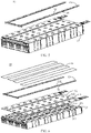
FIG. 5 shows a schematic exploded view of abattery 10 according to an embodiment of the present application. Specifically, as shown inFIG. 5 , thebattery 10 may include abattery cell 20, and eachbattery 10 may include at least onebattery cell 20, for example, inFIG. 5 , the case where thebattery 10 includes 2∗9battery cells 20 is taken as an example. For any one ofbattery cells 20, thebattery cell 20 may include a pressure relief mechanism 213 (not shown inFIG. 5 ), and the pressure relief mechanism is configured to be actuated when an internal pressure or temperature of thebattery cell 20 reaches a threshold, to relieve the internal pressure or temperature. - Optionally, the
pressure relief mechanism 213 may be disposed at any position of thebattery cell 20. It is assumed here that thebattery cell 20 is a cuboid as shown inFIG. 5 , thepressure relief mechanism 213 may be disposed on any one wall of the cuboid. For example, thepressure relief mechanism 213 may be disposed on the uppermost wall of eachbattery cell 20 inFIG. 5 , that is, thepressure relief mechanism 213 and an electrode terminal of thebattery cell 20 may be disposed on the same wall. For ease of description, in the embodiment of the present application, the case where a structure that thepressure relief mechanism 213 and the electrode terminal of thebattery cell 20 are disposed on the same wall is taken as an example for description. - It should be understood that the
battery 10 shown inFIG. 5 may correspond to thebattery 10 shown inFIG. 2 and be applicable to the related description of thebattery 10 shown inFIG. 2 , for example, thebattery 10 shown inFIG. 5 may also include a case and other components. Thebattery cell 20 included in thebattery 10 shown inFIG. 5 may correspond to thebattery cell 20 shown inFIGS. 3 and 4 , and may be applicable to the related descriptions of thebattery cell 20 shown inFIGS. 3 and 4 , for example, thepressure relief mechanism 213 included in thebattery cell 20 shown inFIG. 5 may correspond to thepressure relief mechanism 213 shown inFIG. 4 , which will not be repeated here for brevity. - In addition, as shown in
FIG. 5 , thebattery 10 in the embodiment of the present application may further include a fire-fightingpipeline 13 configured to accommodate a fire-fighting medium. The fire-fightingpipeline 13 may be damaged when thepressure relief mechanism 213 is actuated, so that the fire-fighting medium accommodated therein can be discharged, and the fire-fighting medium can achieve quick cooling and temperature reduction.FIG. 7 shows a schematic diagram of the fire-fightingpipeline 13 shown inFIG. 5 . As shown inFIG. 5 andFIG. 7 , the fire-fightingpipeline 13 may include afirst region 131 and asecond region 132. Thefirst region 131 is disposed corresponding to thepressure relief mechanism 213, so that when thepressure relief mechanism 213 is actuated, thefirst region 131 can be damaged by emissions from thebattery cell 20. Thesecond region 132 is located at the periphery of thefirst region 131. For example, as shown inFIGS. 5 and7 , thefirst region 131 is a segment of pipeline on the fire-fighting pipeline corresponding to thepressure relief mechanism 213 or a part of region toward thepressure relief mechanism 213, and thesecond regions 132 are two segments of pipelines adjacent to thefirst region 131 on two sides of thefirst region 131 or a part of region of the two segments of pipelines adjacent to thefirst region 131 toward thebattery cell 20. Thefirst region 131 is configured to be damaged when thepressure relief mechanism 213 is actuated, such that the fire-fighting medium is discharged, and thesecond region 132 is configured to remain intact when thepressure relief mechanism 213 is actuated, such that the fire-fighting medium is capable of flowing from thesecond region 132 to thefirst region 131. - The
battery 10 in the embodiment of the present application further includes aprotective component 14, which is disposed between the fire-fightingpipeline 13 and thebattery cell 20 and is configured to protect thesecond region 132, such that thesecond region 132 remains intact when thepressure relief mechanism 213 is actuated. - Therefore, the battery 10 of an embodiment of the present application may include one or more battery cells 20, the battery cell 20 is provided with a pressure relief mechanism 213, and the pressure relief mechanism 213 may be actuated when an internal temperature or pressure of the battery cell 20 exceeds a threshold, to relieve the internal pressure or temperature; a fire-fighting pipeline 13 is provided at a position corresponding to the pressure relief mechanism 213, and when the pressure relief mechanism 213 is actuated, emissions discharged from the pressure relief mechanism 213 may damage the fire-fighting pipeline 13, so that a fire-fighting medium accommodated in the fire-fighting pipeline 13 flows out and flows to the pressure relief mechanism 213 so as to lower a temperature of the battery cell 20; meanwhile, a protective component 14 is provided between the fire-fighting pipeline 13 and the battery cell 20, and the protective component 14 may protect a second region 132 on the fire-fighting pipeline 13 located at a periphery of a first region 131 corresponding to the pressure relief mechanism 13, so that the pressure relief mechanism only damages the first region 131 of the fire-fighting pipeline 13 corresponding to the pressure relief mechanism 213, and further a position where the fire-fighting medium in the fire-fighting pipeline 13 flows out is concentrated in a position corresponding to the pressure relief mechanism 213, in this way, the heat dissipation efficiency of the battery cell 20 could be improved, and the fire-fighting medium in the fire-fighting pipeline 13 could be more effectively utilized.
- It should be understood that the
protective component 14 in the embodiment of the present application may protect thesecond region 132, such that thesecond region 132 remains intact when thepressure relief mechanism 213 is actuated, and "intact" here may mean substantially intact. When thepressure relief mechanism 213 is actuated, the discharged high-temperature and high-pressure emissions would melt thefirst region 131 of the fire-fightingpipeline 13, and although thesecond region 132 is provided with theprotective component 14, a small part of thesecond region 132 may be damaged. Therefore, theprotective component 14 can keep thesecond region 132 intact, which may include protecting thesecond region 132 from being completely damaged, or may also include keeping thesecond region 132 substantially intact, that is, thesecond region 132 is substantially protected from being damaged. For example, a region of thesecond region 132 close to thefirst region 131 may be melted in a small range of several millimeters, but the embodiment of the present application is not limited thereto. Optionally, the fire-fightingpipeline 13 in the embodiment of the present application may be set to be any shape according to practical applications. For example, a cross-sectional shape of the fire-fightingpipeline 13 may be set to be any shape according to practical applications. Considering space utilization and convenience for installation, the fire-fightingpipeline 13 may be set as a flat pipeline as shown inFIG. 5 , or may be set to be other shapes, such as a cylindrical pipeline. For ease of description, in the embodiment of the present application, a shape shown inFIG. 5 is taken as an example for description. - In addition, since each battery may include one or
more battery cells 20, when thebattery 10 includes a large number ofbattery cells 20, a plurality ofbattery cells 20 may be arranged in an array, for example, as shown inFIG. 5 , thebattery cell 10 including 2∗9battery cells 20 may be set. Correspondingly, the fire-fightingpipeline 13 provided above thebattery cell 20 may be set as a corresponding shape. For example, for any one row ofbattery cells 20 in thebattery 10, the fire-fightingpipeline 13 may be set as a straight communication pipeline provided above thebattery cell 20, which is controlled by a group of valves. For any two adjacent rows ofbattery cells 20 as shown inFIG. 5 , in order to save space and facilitate control, the fire-fightingpipeline 13 may be set as a U-shaped communication pipeline with one bend, which is controlled by a group of valves. Similarly, for adjacent three rows ofbattery cells 20 included in thebattery 10, the fire-fightingpipeline 13 may also be set as an S-shaped communication pipeline with two bends, which is controlled by a group of valves. By analogy, for any more than three rows ofadjacent battery cells 20 included in thebattery 10, the fire-fightingpipeline 13 may be set as a curved communication pipeline with more bends, which may be controlled by a group of valves, or may be set as a plurality of communication pipelines respectively controlled by a plurality of groups of valves. For example, the plurality of communication pipelines may include at least one of a straight pipeline, a U-shaped pipeline or an S-shaped pipeline, but the embodiment of the present application is not limited thereto. For ease of description, the case where the fire-fightingpipeline 13 is a U-shaped pipeline is taken as an example for description. - In an embodiment of the present application, a group of valves includes an inlet valve and/or an outlet valve, the inlet valve is configured to fill a fire-fighting medium to the fire-fighting
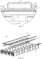
pipeline 13, and the outlet valve is configured to discharge the fire-fighting medium outwards. For example, the circulation of the fire-fighting medium in the fire-fightingpipeline 13 may be achieved by providing the inlet valve and the outlet valve at the same time, so that the fire-fightingpipeline 13 may also be used for cooling or heating when it is not damaged. In addition, the positions of the valves may be set according to practical applications. - It should be understood that the position of the fire-fighting
pipeline 13 in the embodiment of the present application is related to the position of thepressure relief mechanism 213, so that when thepressure relief mechanism 213 is actuated, the discharged emissions can melt thefirst region 131 of the fire-fightingpipeline 13. Specifically,FIG. 6 shows another schematic exploded view of abattery 10 according to an embodiment of the present application. As shown inFIG. 6 , here, the case where apressure relief mechanism 213 included in abattery cell 20 is disposed on the uppermost wall of thebattery cell 20 shown inFIG. 6 is taken as an example, the wall is a cover plate of thebattery cell 20, and the cover plate also includes anelectrode terminal 214. As shown inFIG. 6 , a fire-fightingpipeline 13 is arranged at a position corresponding to thepressure relief mechanism 213, which includes according to the position of thepressure relief mechanism 213, arranging the fire-fightingpipeline 13 at a side of thepressure relief mechanism 213 away from an interior of thebattery cell 20, that is, the fire-fightingpipeline 13 can be arranged above thepressure relief mechanism 213 so that the fire-fightingpipeline 13 may at least partially cover thepressure relief mechanism 213. In this way, when thepressure relief mechanism 213 is actuated, the ejected emissions may damage the fire-fightingpipeline 13, so that the fire-fighting medium in the fire-fightingpipeline 13 may flow into the battery cell where thermal runaway occurs, through thepressure relief mechanism 213. - In addition, as shown in
FIG. 6 , thebattery 10 may further include an insulatinglayer 12, the insulatinglayer 12 is disposed between thepressure relief mechanism 213 and the fire-fightingpipeline 13, and further, disposed between thepressure relief mechanism 213 and theprotective component 14. For example, the insulatinglayer 12 inFIG. 6 is provided on a surface of thebattery cell 20 shown inFIG. 5 . - As shown in
FIG. 6 , when thepressure relief mechanism 213 is actuated, a position corresponding to the insulatinglayer 12 covered above thepressure relief mechanism 213 can be quickly melted by emissions discharged from thepressure relief mechanism 213, to relieve an internal temperature and pressure of thebattery cell 20. Therefore, a melting point of the material at the position on the insulatinglayer 12 corresponding to thepressure relief mechanism 213 is generally low. - It should be understood that the insulating
layer 12 in the embodiment of the present application is used for insulation between the wall where thepressure relief mechanism 213 is located and the fire-fightingpipeline 13; the insulatinglayer 12 may also be configured to wrap a bus component, and the bus component is configured to implement electrical connection ofelectrode terminals 214 ofdifferent battery cells 20, for example, abus component 122 is located at a position on the insulatinglayer 12 corresponding to theelectrode terminal 214 inFIG. 6 ; the insulatinglayer 12 may also be configured to wrap other structures disposed on the surface of the wall where thepressure relief mechanism 213 is located. For example, the insulatinglayer 12 may also be configured to wrap a flexible printed circuit (Flexible Printed Circuit, FPC) board, and the FPC may be configured to monitor a state of eachbattery cell 20, for example, to monitor a temperature state or voltage state thereof, but the embodiment of the present application is not limited thereto. - Considering that one or
more battery cells 20 may be provided in thebattery 10, in the case where a large number ofbattery cells 20 are provided, there may be a large number of bus components or FPCs and other components connecting eachbattery cell 20, which have a large area, and therefore these components may be integrated through the insulatinglayer 12 to make the assembling of the plurality ofbattery cells 20 more convenient. For example, 2∗9battery cells 20 shown inFIG. 6 may be correspondingly provided with one insulatinglayer 12. - Optionally, as shown in
FIG. 6 , thebattery 10 of the embodiment of the present application further includes an insulatingprotective layer 15 configured to protect thebus component 122. Specifically, when the thermal runaway occurs in thebattery cell 20, thepressure relief mechanism 213 is actuated and discharges the emissions, and the emissions may melt the insulatinglayer 12 to expose thebus components 122, thereby causing the emissions or the fire-fighting medium in the fire-fightingpipeline 13 to flow to thebus component 122, and further causing the overlap and short circuit between the plurality ofadjacent bus components 122 for connecting different battery cells. Therefore, the insulatingprotective layer 15 is set to protect thebus component 122 from the influence of the emissions or the fire-fighting medium in the fire-fightingpipeline 13. For example, an insulating and high-temperature resistant material may be selected for the insulatingprotective layer 15, and the insulatingprotective layer 15 may be disposed on a surface of thebus component 122 or disposed at a position on a surface of the insulatinglayer 12 corresponding to thebus component 122, to protect thebus component 122. - In addition, a shape and size of the insulating
protective layer 15 in the embodiment of the present application may be set according to the practical applications. For example, considering that the plurality ofbattery cells 20 are generally arranged in an array as shown inFIG. 6 , in order to facilitate installation, the insulatingprotective layer 15 may be set as a long strip shape as shown inFIG. 6 , and each of the insulatingprotective layers 15 may be configured to cover and protect a row ofbus components 122, but the embodiment of the present application is not limited thereto. Furthermore, theprotective component 14 and the insulatingprotective layer 15 may be independent structures, for example, the insulatingprotective layer 15 may be attached to an upper surface of theprotective component 14 through a connecting member, and the connecting member may be glue, etc. or, theprotective component 14 and the insulatingprotective layer 15 may also be an integrally formed structure, and the embodiment of the present application is not limited thereto. In order to ensure the strength of the insulatingprotective layer 15, a thickness of the insulatingprotective layer 15 is greater than 0.1 mm. - It should be understood that the
protective component 14 in the embodiment of the present application may include various forms, and batteries including differentprotective components 14 will be respectively illustrated below with reference to the accompanying drawings. - Optionally, as a first embodiment, as shown in
FIGS. 5 to 7 , theprotective component 14 may be a component only provided in thesecond region 132 of the fire-fightingpipeline 13. Specifically, takingFIGS. 6 and7 as an example, theprotective component 14 may be disposed between thesecond region 132 of the fire-fightingpipeline 13 and thebattery cell 20, and configured to protect thesecond region 132 when thepressure relief mechanism 213 is actuated, for example, theprotective component 14 may be wrapped on a surface of thesecond region 132. - Specifically, as shown in
FIG. 6 andFIG. 7 , when theprotective component 14 is set as a component that wraps thesecond region 132, theprotective component 14 and the fire-fightingpipeline 13 are still in a shape of a pipeline as a whole, and therefore theprotective component 14 and the fire-fightingpipeline 13 may be installed by setting a recess. As shown inFIG. 6 , asecond recess 121 may be provided in a region of the insulatinglayer 12 corresponding to thepressure relief mechanism 213, and the fire-fightingpipeline 13 wrapped by theprotective component 14 is disposed in thesecond recess 121. - In order to ensure that the emissions discharged by the
pressure relief mechanism 213 can quickly and effectively damage thefirst region 131 of the fire-fightingpipeline 13, the fire-fightingpipeline 13 is generally disposed right above thepressure relief mechanism 213, so that thefirst region 131 directly faces thepressure relief mechanism 213. For example, thepressure relief mechanism 213 is generally axisymmetric, and an axis of thepressure relief mechanism 213 is perpendicular to and lies in a same plane as an axis of the correspondingfirst region 131; that is, thefirst region 131 directly faces thepressure relief mechanism 213. For example, as shown inFIG. 6 , thesecond recess 121 is disposed right above thepressure relief mechanism 213, and the fire-fightingpipeline 13 is disposed in thesecond recess 121 to ensure that the fire-fightingpipeline 13 is disposed right above thepressure relief mechanism 213. - Optionally, in order to enable the
protective component 14 to protect thesecond region 132 when thepressure relief mechanism 213 is actuated, a melting point of a material of theprotection part 14 should be greater than a melting point of a material of the fire-fightingpipeline 13. Specifically, a material with a higher melting point is generally selected for theprotective component 14. For example, a melting point of a material of theprotective component 14 is greater than or equal to 800°C, and the material of theprotective component 14 may be mica, quartz, etc., but the embodiment of the present application is not limited thereto. - The
first region 131 and thesecond region 132 included in the fire-fightingpipeline 13 in an embodiment of the present application will be described below. Specifically, the division of thefirst region 131 and thesecond region 132 may be for the entire fire-fightingpipeline 13, or may also be for a side of the fire-fightingpipeline 13 facing thebattery cell 20. For example, in combination withFIG. 6 andFIG. 7 , thefirst region 131 in the embodiment of the present application may be a segment of pipeline in the fire-fightingpipeline 13 corresponding to thepressure relief mechanism 213, that is, thefirst region 131 is a segment of pipeline directly facing thepressure relief mechanism 213, or thefirst region 131 may also refer to a region on the surface of the fire-fightingpipeline 13 facing thebattery cell 20 corresponding to thepressure relief mechanism 213, that is, thefirst region 131 is a region directly facing thepressure relief mechanism 213; similar to the division manner of thefirst region 131, thesecond region 132 is located at the periphery of thefirst region 131, that is, eachsecond region 132 is a segment of pipeline adjacent to thefirst region 131, or eachsecond region 132 is a region adjacent to thefirst region 131. In addition, when thefirst region 131 represents a segment of pipeline, thesecond region 132 may refer to either a segment of pipeline or a region; and when thefirst region 131 represents a region, thesecond region 132 may refer to either a segment of pipeline or a region, which is not limited thereto. However, for ease of description, the case where both thefirst region 131 and thesecond region 132 represent a segment of pipeline is taken as an example. - In addition, in an embodiment of the present application, the
second region 132 located at the periphery of thefirst region 131 may include a plurality of division manners. Specifically, for ease of description, as shown inFIG. 7 , in an embodiment of the present application, an extending direction of the fire-fightingpipeline 13 is defined as the X direction, that is, an axis direction of the fire-fightingpipeline 13 is defined as the X direction. As shown inFIG. 7 , two ends of any segment of thefirst region 131 along the X direction is provided withsecond regions 132, but the sizes of thesecond regions 132 may be set to be different, so a segment of second region 132 (for example, as shown inFIG. 7 ) or two segments of discontinuoussecond regions 132 may be provided between two continuousfirst regions 131 along the X direction, and eachsecond region 132 is respectively adjacent to the correspondingfirst region 131. - However, for ease of description, the division manner in
FIG. 7 is taken as an example for description, that is, two ends of any one segment of thefirst region 131 along the X direction aresecond regions 132, and a segment of pipeline between two continuousfirst regions 131 corresponding to thepressure relief mechanisms 213 of any twoadjacent battery cells 20 along the X direction is thesecond region 132; and similarly, two ends of any one segment of thesecond region 132 along the X direction are thefirst regions 131. - Optionally, lengths of the
first region 131 and thesecond region 132 along the X direction in an embodiment of the present application may be set according to the practical applications, and the embodiment of the present application is not limited thereto. For example, a length of thefirst region 131 along the X direction may be set according to a size of thepressure relief mechanism 213, or may be set according to a distance between the fire-fightingpipeline 13 and thepressure relief mechanism 213. For example, the length of thefirst region 131 along the X direction may be greater than or equal to the length of thepressure relief mechanism 213 along the X direction, and thesecond region 132 is a pipeline of the fire-fightingpipeline 13 between twofirst regions 131 corresponding to two adjacentpressure relief mechanisms 213. - It should be understood that a width of the fire-fighting
pipeline 13 in an embodiment of the present application may be set according to the practical applications. For example,FIG. 8 shows a top view of abattery 10 including a fire-fightingpipeline 13 and abattery cell 20, that is,FIG. 8 is a top view of thebattery 10 shown inFIG. 6 after installation. As shown inFIG. 8 , for ease of explanation, a direction perpendicular to the X direction is referred to as a first direction and is denoted as the Y direction. In combination withFIG. 6 andFIG. 8 , it can be seen that since the fire-fightingpipeline 13 is disposed in thesecond recess 121 of the insulatinglayer 12, in the Y direction, a width of the fire-fightingpipeline 13 is less than or equal to a width of thesecond recess 121. In the Y direction, a width of the insulatingprotective layer 15 may be set according to the practical applications, for example, the width of the insulatingprotective layer 15 may be set according to a width of thebus component 122 along the Y direction. - In addition,
FIG. 9 is a partial enlarged view of a cross-sectional view of thebattery 10 shown inFIG. 8 along the direction A-A shown inFIG. 8 . As shown inFIG. 9 , in order to ensure that thepressure relief mechanism 213 can successfully damage thefirst region 131 of the fire-fightingpipeline 13, in the Y direction, the width of thepressure relief mechanism 213 is generally set to be greater than or equal to the width of the fire-fightingpipeline 13, so as to easily damage the fire-fightingpipeline 13, but the embodiment of the present application is not limited thereto. - Optionally, as shown in
FIG. 9 , in order to be able to fix the fire-fightingpipeline 13 provided with theprotective component 14, a fixingmember 123 may be provided on the insulatinglayer 12. Specifically, the fixingmember 123 may be provided in thesecond recess 121 on the insulatinglayer 12, and the fixingmember 123 is configured to fix the fire-fightingpipeline 13 having theprotective component 14. Optionally, the fixingmember 123 may be any structure capable of fixing the fire-fightingpipeline 13, for example, as shown inFIGS. 8 and9 , the fixingmember 123 may be a buckle, but the embodiment of the present application is not limited thereto. - In the foregoing description, the case where the
protective component 14 is a structure disposed in thesecond region 132 in segments is taken as an example. In contrast, theprotective component 14 may also be an integral structure disposed between thepressure relief mechanism 213 and the fire-fightingpipeline 13. - Optionally, as a second embodiment which is different from the first embodiment in which the
protective component 14 is a plurality of separate structures, for example, each separate structure is only configured to protect a segment of thesecond region 132 in the fire-fightingpipeline 13, and theprotective component 14 in an embodiment of the present application may also be one or more continuous structures, and each continuous structure may protect a plurality of segments of thesecond region 132 in the fire-fightingpipeline 13. For example,FIG. 10 shows a schematic exploded view of abattery 10 according to a second embodiment of the present application. As shown inFIG. 10 , aprotective component 14 may be disposed between a fire-fightingpipeline 13 and a pressure relief mechanism 213 (not shown inFIG. 10 ). For the description of the remaining parts inFIG. 10 except theprotective component 14, reference may be made to the related content inFIG. 5 , which will not be repeated here for brevity. - The
protective component 14 inFIG. 10 will be described in detail with reference to the accompanying drawings. Specifically,FIG. 11 shows a schematic diagram of theprotective component 14 inFIG. 10 . As shown inFIG. 11 , in the case where the fire-fightingpipeline 13 is still divided into thefirst region 131 and thesecond region 132 as shown inFIG. 7 , correspondingly, along the X direction, theprotective component 14 may include aprotective zone 142 and a weakenedzone 141. Specifically, with reference toFIGS. 7 ,10 and11 , the weakenedzone 141 corresponds to thefirst region 131, and theprotective zone 142 corresponds to thesecond region 132. Optionally, theprotective zone 142 is a zone other than the weakenedzone 141. After theprotective component 14 and the fire-fightingpipeline 13 are installed, theprotective zone 142 covers thesecond region 132, for example, theprotective zone 142 can cover a region of a side of thesecond region 132 toward thebattery cell 20, and theprotective zone 142 is configured to protect thesecond region 132 of the fire-fightingpipeline 13 when thepressure relief mechanism 213 is actuated, and the weakenedzone 141 covers thefirst region 131 and is disposed opposite to thepressure relief mechanism 213, and the weakenedzone 141 is configured such that emissions from thebattery cell 20 are capable of passing through the weakenedzone 141 to damage thefirst region 131 when thepressure relief mechanism 213 is actuated. In this way, when thepressure relief mechanism 213 is actuated, it can be ensured that thefirst region 131 of the fire-fightingpipeline 13 is damaged and thesecond region 132 remains intact, and the fire-fighting medium in thesecond region 132 flows to thefirst region 131, and passes through thefirst region 131 and then flows out to the battery cell where thermal runaway occurs, thus achieving the effect of temperature reduction and heat dissipation. - Optionally, the weakened
zone 141 in an embodiment of the present application may be a through hole or be made of a material with a lower melting point, so as to ensure that the emissions from thebattery cell 20 pass through the weakened zone via thepressure relief mechanism 213 to damage thefirst region 131 ; on the contrary, theprotective zone 142 is made of a material with a higher melting point to ensure that it is not melted by the emissions from thebattery cell 20, thereby protecting thesecond region 132. Specifically, a melting point of a material of theprotection part 14 at theprotective zone 142 should be greater than a melting point of a material of the fire-fightingpipeline 13. For example, a melting point of a material of theprotective component 14 is greater than or equal to 800°C, and the material of theprotective component 14 may be mica, quartz, etc., but the embodiment of the present application is not limited thereto. - It should be understood that, as shown in
FIG. 11 , theprotective component 14 is also provided with afirst recess 143, and the fire-fightingpipeline 13 is disposed in thefirst recess 143, and the weakenedzone 141 is provided in a region on a bottom wall of thefirst recess 143 corresponding to thefirst region 131. Thefirst recess 143 may be configured to collect the fire-fighting medium used to flow into thebattery cell 20 when thepressure relief mechanism 213 is actuated. -
FIG. 12 shows another schematic exploded view of abattery 10 according to a second embodiment of the present application. As shown inFIG. 12 , a fire-fightingpipeline 13 may be fixed in afirst recess 143 of aprotective component 14, and the fire-fightingpipeline 13 and theprotective component 14 may be fixed in asecond recess 121 of an insulatinglayer 12, and an insulatingprotective layer 15 covers a region on a surface of the insulatinglayer 12 corresponding to abus component 122. Specifically, the insulatinglayer 12 inFIG. 12 may correspond to the insulatinglayer 12 inFIG. 6 , that is, the related description of the insulatinglayer 12 inFIG. 6 is applicable to the insulatinglayer 12 inFIG. 12 , which will not be repeated here for brevity. Furthermore, an upper surface of thebattery cell 20 shown inFIG. 11 is provided with the insulatinglayer 12 shown inFIG. 12 . - As shown in
FIG. 12 , the insulatinglayer 12 is provided with thesecond recess 121 corresponding to thepressure relief mechanism 213, so that theprotective component 14 installed with the fire-fightingpipeline 13 is disposed in thesecond recess 121. - It should be understood that, similar to the first embodiment, in order to ensure that the emissions discharged from the
pressure relief mechanism 213 can quickly and effectively pass through the weakenedzone 141 to damage thefirst region 131 of the fire-fightingpipeline 13, the weakenedzone 141 should be disposed right above thepressure relief mechanism 213, and meanwhile thefirst region 131 directly faces thepressure relief mechanism 213. For example,FIG. 13 shows a top view of abattery 10 according to a second embodiment of the present application. In combination withFIGS. 10 and13 , thepressure relief mechanism 213 is generally axisymmetric, and an axis of thepressure relief mechanism 213 is perpendicular to and lies in a same plane as an axis of the correspondingfirst region 131; that is, thefirst region 131 directly faces thepressure relief mechanism 213. In addition, an orthographic projection of the weakenedzone 141 on a first plane covers an orthographic projection of thepressure relief mechanism 213 on the first plane, so that the weakenedzone 141 also directly faces thepressure relief mechanism 213, or it can cover thepressure relief mechanism 213, where the first plane is parallel to an upper or lower surface of the wall where thepressure relief mechanism 213 of thebattery cell 20 is located, the upper surface is a surface away from an interior of thebattery cell 20, and the lower surface is a surface toward the interior of thebattery cell 20. - In the embodiment of the present application, the size of the fire-fighting
pipeline 13 and the size of theprotective component 14 can be set according to the practical applications. In combination withFIG. 12 and FIG. 13 , it can be seen that since the fire-fightingpipeline 13 is disposed in thefirst recess 143 of theprotective component 14 and theprotective component 14 is disposed in thesecond recess 121 of the insulatinglayer 12, in the Y direction, a width of the fire-fightingpipeline 13 is less than or equal to a width of a bottom wall of thefirst recess 143, and the width of the bottom wall of thefirst recess 143 is less than or equal to a width of a bottom wall of thesecond recess 121. In addition, in the Y direction, a width of the insulatingprotective layer 15 may be set according to the practical applications, for example, the width of the insulatingprotective layer 15 may be set according to a direction of thebus component 122 along the Y direction. In this case, when the widths of the fire-fightingpipelines 13 are inconsistent, the width of the fire-fightingpipeline 13 may refer to a width at a position where the fire-fightingpipeline 13 is the smallest width in the Y direction. - In addition, in order to make the emissions discharged from the
pressure relief mechanism 213 quickly and accurately pass through the weakenedzone 141 to break through thefirst region 131, in the Y direction, a width of the weakenedzone 141 is generally larger than a diameter of the fire-fightingpipeline 13; however in the Y direction, the width of the weakenedzone 141 may be greater than, less than or equal to a width of a bottom wall of thefirst recess 143. For example, as shown inFIG. 13 , the width of the weakenedzone 141 may be greater than the width of the bottom wall of thefirst recess 143, so that thefirst region 131 may be fully exposed through the weakenedzone 141, thus ensuring that thefirst region 131 is more easily damaged when thepressure relief mechanism 213 is actuated, but the embodiment of the present application is not limited thereto. -
FIG. 14 is a partial enlarged view of a cross-sectional view of thebattery 10 shown inFIG. 13 along the direction B-B shown inFIG. 13 . As shown inFIG. 14 , in order to ensure that thepressure relief mechanism 213 can damage thefirst region 131 of the fire-fightingpipeline 13, in the Y direction, the width of thepressure relief mechanism 213 is generally set to be greater than or equal to the width of the fire-fightingpipeline 13, but the embodiment of the present application is not limited thereto. - In addition, similar to
FIG. 9 , in order to be able to fix the fire-fightingpipeline 13 provided with theprotective component 14, a fixingmember 123 may also be provided on the insulatinglayer 12, which will not be repeated here for brevity. - Therefore, the battery 10 of an embodiment of the present application may include one or more battery cells 20, the battery cell 20 is provided with a pressure relief mechanism 213, and the pressure relief mechanism 213 may be actuated when an internal temperature or pressure of the battery cell 20 exceeds a threshold, to relieve the internal pressure or temperature; a fire-fighting pipeline 13 is provided at a position corresponding to the pressure relief mechanism 213, and when the pressure relief mechanism 213 is actuated, emissions discharged from the pressure relief mechanism 213 may damage the fire-fighting pipeline 13, so that a fire-fighting medium accommodated in the fire-fighting pipeline 13 flows out from a damaged position and flows to the pressure relief mechanism 213 so as to lower a temperature of the battery cell 20; meanwhile, a protective component 14 is provided between the fire-fighting pipeline 13 and the battery cell 20, and the protective component 14 may protect a second region 132 on the fire-fighting pipeline 13 located at a periphery of a first region 131 corresponding to the pressure relief mechanism 13, so that the pressure relief mechanism 213 only damages the first region 131 of the fire-fighting pipeline 13 corresponding to the pressure relief mechanism 213, and further a position where the fire-fighting medium in the fire-fighting pipeline 13 flows out is concentrated in a position corresponding to the pressure relief mechanism 213, in this way, the heat dissipation efficiency of the battery cell 20 could be improved, and the fire-fighting medium in the fire-fighting pipeline 13 could be more effectively utilized.
- An embodiment of the present application further provides a power consumption device, which may include the
battery 10 in each of the foregoing embodiments. Optionally, the power consumption device may be avehicle 1, a ship or a spacecraft. - The battery and the power consumption device of the embodiment of the present application are described above, and a method and a device for producing a battery of an embodiment of the present application will be described below. For the parts that are not described in detail, reference is made to the foregoing embodiments.
-
FIG. 15 shows a schematic flowchart of amethod 300 for producing a battery according to an embodiment of the present application. As shown inFIG. 15 , themethod 300 may include: 310, providing abattery cell 20, thebattery cell 20 including apressure relief mechanism 213 configured to be actuated when an internal pressure or temperature of thebattery cell 20 reaches a threshold, to relieve the internal pressure or temperature; 320, providing a fire-fightingpipeline 13, the fire-fightingpipeline 13 being configured to accommodate a fire-fighting medium, the fire-fightingpipeline 13 including afirst region 131 corresponding to thepressure relief mechanism 213 and asecond region 132 located at a periphery of thefirst region 131, thefirst region 131 being configured to be damaged when thepressure relief mechanism 213 is actuated, such that the fire-fighting medium is discharged, and thesecond region 132 being configured to remain intact when thepressure relief mechanism 213 is actuated, such that the fire-fighting medium is capable of flowing from thesecond region 132 to thefirst region 131; and 330, providing aprotective component 14, theprotective component 14 being disposed between the fire-fightingpipeline 13 and thebattery cell 20, and theprotective component 14 being configured to protect thesecond region 132. -
FIG. 16 shows a schematic block diagram of adevice 400 for producing a battery according to an embodiment of the present application. As shown inFIG. 16 , thedevice 400 for producing a battery may include aprovision module 410. Theprovision module 410 is configured to: provide abattery cell 20, thebattery cell 20 including apressure relief mechanism 213 configured to be actuated when an internal pressure or temperature of thebattery cell 20 reaches a threshold, to relieve the internal pressure or temperature; provide a fire-fightingpipeline 13, the fire-fightingpipeline 13 being configured to accommodate a fire-fighting medium, the fire-fightingpipeline 13 including afirst region 131 corresponding to thepressure relief mechanism 213 and asecond region 132 located at a periphery of thefirst region 131, thefirst region 131 being configured to be damaged when thepressure relief mechanism 213 is actuated, such that the fire-fighting medium is discharged, and thesecond region 132 being configured to remain intact when thepressure relief mechanism 213 is actuated, such that the fire-fighting medium is capable of flowing from thesecond region 132 to thefirst region 131; and provide aprotective component 14, theprotective component 14 being disposed between the fire-fightingpipeline 13 and thebattery cell 20, and theprotective component 14 being configured to protect thesecond region 132. - Finally, it should be noted that the above embodiments are merely used for illustrating rather than limiting the technical solutions of the present application. Although the present application is illustrated in detail with reference to the foregoing embodiments, those of ordinary skill in the art should understand that they can still modify the technical solutions described in the foregoing embodiments, or make equivalent substitutions to some of the technical features therein, but these modifications or substitutions do not make the nature of the respective technical solutions depart from the spirit and scope of the technical solutions of the embodiments of the present application.
Claims (31)
- A battery, comprising:a battery cell (20), the battery cell (20) comprising a pressure relief mechanism (213), the pressure relief mechanism (213) configured to be actuated when an internal pressure or temperature of the battery cell (20) reaches a threshold, to relieve the internal pressure or temperature;a fire-fighting pipeline (13) configured to accommodate a fire-fighting medium, the fire-fighting pipeline (13) comprising a first region (131) corresponding to the pressure relief mechanism (213) and a second region (132) located at a periphery of the first region (131), the first region (131) being configured to be damaged when the pressure relief mechanism (213) is actuated, such that the fire-fighting medium is discharged, and the second region (132) being configured to remain intact when the pressure relief mechanism (213) is actuated, such that the fire-fighting medium is capable of flowing from the second region (132) to the first region (131); anda protective component (14) disposed between the fire-fighting pipeline (13) and the battery cell (20) and configured to protect the second region (132).
- The battery according to claim 1, wherein the protective component (14) is disposed between the second region (132) of the fire-fighting pipeline (13) and the battery cell (20), and the protective component (14) is configured to protect the second region (132) when the pressure relief mechanism (213) is actuated.
- The battery according to claim 1, wherein the protective component (14) comprises a weakened zone (141) and a protective zone (142), the protective zone (142) is configured to protect the second region (132) of the fire-fighting pipeline (13) when the pressure relief mechanism (213) is actuated, the weakened zone is disposed opposite to the pressure relief mechanism (213), and the weakened zone (141) is configured such that emissions from the battery cell (20) are capable of passing through the weakened zone (141) to damage the first region (131) when the pressure relief mechanism (213) is actuated.
- The battery according to claim 3, wherein a first recess (143) is provided on the protective component (14), the fire-fighting pipeline (13) is disposed in the first recess (143), and the first recess (143) is configured to collect the fire-fighting medium used to flow into the battery cell (213) when the pressure relief mechanism (213) is actuated.
- The battery according to claim 4, wherein the weakened zone (141) is provided in a region on a bottom wall of the first recess (143) corresponding to the first region (131).
- The battery according to claim 5, wherein a width of the weakened zone (141) in a first direction is greater than or equal to a width of the bottom wall of the first recess (143) in the first direction, and the first direction is perpendicular to an axis of the fire-fighting pipeline (13) in the first region (131).
- The battery according to any one of claims 3 to 6, wherein a width of the weakened zone (141) in a first direction is greater than a diameter of the fire-fighting pipeline (13), and the first direction is perpendicular to an axis of the fire-fighting pipeline (13) in the first region (131).
- The battery according to any one of claims 3 to 7, wherein an orthographic projection of the weakened zone (141) on a first plane covers an orthographic projection of the pressure relief mechanism (213) on the first plane, and the first plane is parallel to a surface of a wall where the pressure relief mechanism (213) of the battery cell (20) is located facing toward an interior of the battery cell (20).
- The battery according to any one of claims 1 to 8, wherein the fire-fighting pipeline (13) is disposed on one side of the pressure relief mechanism (213) away from an interior of the battery cell (20).
- The battery according to claim 9, wherein the pressure relief mechanism (213) is an axisymmetric structure, and an axis of the fire-fighting pipeline (13) in the first region (131) is perpendicular to and lies in a same plane as an axis of the pressure relief mechanism (213).
- The battery according to any one of claims 1 to 10, wherein a melting point of a material of the protective component (14) is greater than a melting point of a material of the fire-fighting pipeline (13).
- The battery according to any one of claims 1 to 11, wherein a melting point of a material of the protective component (14) is greater than or equal to 800°C.
- The battery according to any one of claims 1 to 12, wherein a material of the protective component (14) is mica or quartz.
- The battery according to any one of claims 1 to 13, wherein the battery further comprises:a bus component (122) configured to implement electrical connection of a plurality of battery cells (20); andan insulating protective layer (15) configured to cover the bus component (122) to prevent emissions from the battery cell (20) from short-circuiting the plurality of the battery cells (20) when the pressure relief mechanism (213) is actuated, and a thickness of the insulating protective layer is greater than 0.1 mm.
- The battery according to claim 14, wherein a melting point of a material of the insulating protective layer (15) is greater than or equal to 800°C; and/or
a material of the insulating protective layer (15) is mica or quartz. - The battery according to any one of claims 1 to 15, wherein the battery further comprises:
an insulating layer (12) disposed between the pressure relief mechanism (213) and the protective component (14). - The battery according to claim 16, wherein the insulating layer (12) is configured to wrap a bus component (122) of the battery, and an insulating protective layer (15) is provided in a region on a surface of the insulating layer (12) corresponding to the bus component (122),
wherein the bus component (122) is configured to implement electrical connection of a plurality of battery cells (20), and the insulating protective layer (15) is configured to cover the bus component (122) to prevent emissions from the battery cell (20) from short-circuiting the plurality of the battery cells (20) when the pressure relief mechanism (213) is actuated. - The battery according to claim 17, wherein the protective component (14) and the insulating protective layer (15) are an integrally formed structure.
- The battery according to any one of claims 16 to 18, wherein a second recess (121) is provided in a region of the insulating layer (12) corresponding to the pressure relief mechanism (213), and the protective component (14) is disposed in the second recess (121).
- The battery according to claim 19, wherein a first recess (143) on the protective component (14) is disposed in the second recess (121), the fire-fighting pipeline (13) is disposed in the first recess (143), and the first recess (143) is configured to collect the fire-fighting medium used to flow into the battery cell (213) when the pressure relief mechanism (213) is actuated.
- The battery according to claim 19 or 20, wherein a fixing member (123) is provided in the second recess (121), and the fixing member (123) is configured to fix the protective component (14) and the fire-fighting pipeline (13).
- The battery according to any one of claims 16 to 21, wherein a melting point of a material of the insulating layer (12) is lower than a melting point of the protective component (14), and the insulating layer (12) is melted by emissions from the battery cell (20) when the pressure relief mechanism (213) is actuated.
- A power consumption device, comprising the battery according to any one of claims 1 to 22.
- A method for producing a battery, comprising:providing a battery cell, the battery cell comprising a pressure relief mechanism configured to be actuated when an internal pressure or temperature of the battery cell reaches a threshold, to relieve the internal pressure or temperature;providing a fire-fighting pipeline, the fire-fighting pipeline being configured to accommodate a fire-fighting medium, the fire-fighting pipeline comprising a first region corresponding to the pressure relief mechanism and a second region located at a periphery of the first region, the first region being configured to be damaged when the pressure relief mechanism is actuated, such that the fire-fighting medium is discharged, and the second region being configured to remain intact when the pressure relief mechanism is actuated, such that the fire-fighting medium is capable of flowing from the second region to the first region; andproviding a protective component, the protective component being disposed between the fire-fighting pipeline and the battery cell, and the protective component being configured to protect the second region.
- The method according to claim 24, wherein the protective component is disposed between the second region of the fire-fighting pipeline and the battery cell, and the protective component is configured to protect the second region when the pressure relief mechanism is actuated.
- The method according to claim 24, wherein the protective component comprises a protective zone and a weakened zone, the protective zone is configured to protect the second region of the fire-fighting pipeline when the pressure relief mechanism is actuated, the weakened zone is disposed opposite to the pressure relief mechanism, and the weakened zone is configured such that emissions from the battery cell are capable of passing through the weakened zone to damage the first region when the pressure relief mechanism is actuated.
- The method according to claim 26, wherein a first recess is provided on the protective component, the fire-fighting pipeline is disposed in the first recess, and the first recess is configured to collect the fire-fighting medium used to flow into the battery cell when the pressure relief mechanism is actuated.
- A device for producing a battery, comprising: a provision module configured to:provide a battery cell, the battery cell comprising a pressure relief mechanism, the pressure relief mechanism configured to be actuated when an internal pressure or temperature of the battery cell reaches a threshold, to relieve the internal pressure or temperature;provide a fire-fighting pipeline, the fire-fighting pipeline being configured to accommodate a fire-fighting medium, the fire-fighting pipeline comprising a first region corresponding to the pressure relief mechanism and a second region located at a periphery of the first region, the first region being configured to be damaged when the pressure relief mechanism is actuated, such that the fire-fighting medium is discharged, and the second region being configured to remain intact when the pressure relief mechanism is actuated, such that the fire-fighting medium is capable of flowing from the second region to the first region; andprovide a protective component, the protective component being disposed between the fire-fighting pipeline and the battery cell, and the protective component being configured to protect the second region.
- The device according to claim 28, wherein the protective component is disposed between the second region of the fire-fighting pipeline and the battery cell, and the protective component is configured to protect the second region when the pressure relief mechanism is actuated.
- The device according to claim 28, wherein the protective component comprises a protective zone and a weakened zone, the protective zone is configured to protect the second region of the fire-fighting pipeline when the pressure relief mechanism is actuated, the weakened zone is disposed opposite to the pressure relief mechanism, and the weakened zone is configured such that emissions from the battery cell are capable of passing through the weakened zone to damage the first region when the pressure relief mechanism is actuated.
- The device according to claim 30, wherein a first recess is provided on the protective component, the fire-fighting pipeline is disposed in the first recess, and the first recess is configured to collect the fire-fighting medium used to flow into the battery cell when the pressure relief mechanism is actuated.
Priority Applications (1)
| Application Number | Priority Date | Filing Date | Title |
|---|---|---|---|
| HUE20827955A HUE063718T2 (en) | 2020-10-19 | 2020-10-19 | Battery and power utilization device |
Applications Claiming Priority (1)
| Application Number | Priority Date | Filing Date | Title |
|---|---|---|---|
| PCT/CN2020/121992 WO2022082389A1 (en) | 2020-10-19 | 2020-10-19 | Battery, power utilization device, and battery preparation method and apparatus |
Publications (3)
| Publication Number | Publication Date |
|---|---|
| EP4009434A1 true EP4009434A1 (en) | 2022-06-08 |
| EP4009434A4 EP4009434A4 (en) | 2022-06-08 |
| EP4009434B1 EP4009434B1 (en) | 2023-08-02 |
Family
ID=81186884
Family Applications (1)
| Application Number | Title | Priority Date | Filing Date |
|---|---|---|---|
| EP20827955.4A Active EP4009434B1 (en) | 2020-10-19 | 2020-10-19 | Battery and power utilization device |
Country Status (6)
| Country | Link |
|---|---|
| US (1) | US20220118861A1 (en) |
| EP (1) | EP4009434B1 (en) |
| JP (1) | JP7350213B2 (en) |
| KR (1) | KR102646202B1 (en) |
| HU (1) | HUE063718T2 (en) |
| WO (1) | WO2022082389A1 (en) |
Family Cites Families (10)
| Publication number | Priority date | Publication date | Assignee | Title |
|---|---|---|---|---|
| US9093726B2 (en) | 2009-09-12 | 2015-07-28 | Tesla Motors, Inc. | Active thermal runaway mitigation system for use within a battery pack |
| DE102011075318A1 (en) * | 2011-05-05 | 2012-11-08 | Sb Limotive Company Ltd. | Battery housing for lithium-ion cells |
| DE102011109249A1 (en) * | 2011-08-02 | 2013-02-07 | Daimler Ag | High voltage battery for vehicle applications |
| CN106785182B (en) * | 2015-11-23 | 2019-06-11 | 宁德时代新能源科技股份有限公司 | Battery pack |
| JP2017147128A (en) | 2016-02-17 | 2017-08-24 | 三菱重工業株式会社 | Battery module and battery system |
| US20180138478A1 (en) | 2016-11-14 | 2018-05-17 | Anhui Xinen Technology Co., Ltd. | Alleviating explosion propagation in a battery module |
| EP3333932B1 (en) * | 2016-12-06 | 2019-02-13 | Samsung SDI Co., Ltd. | Battery system |
| JP2019029245A (en) | 2017-08-01 | 2019-02-21 | 株式会社Gsユアサ | Power storage device |
| CN209104233U (en) | 2018-12-28 | 2019-07-12 | 宁德时代新能源科技股份有限公司 | A kind of the spray pipeline component and battery pack of battery pack |
| CN209662489U (en) | 2018-12-28 | 2019-11-22 | 宁德时代新能源科技股份有限公司 | A kind of spray pipeline component of battery pack, battery pack |
-
2020
- 2020-10-19 JP JP2023504066A patent/JP7350213B2/en active Active
- 2020-10-19 HU HUE20827955A patent/HUE063718T2/en unknown
- 2020-10-19 KR KR1020237001610A patent/KR102646202B1/en active IP Right Grant
- 2020-10-19 EP EP20827955.4A patent/EP4009434B1/en active Active
- 2020-10-19 WO PCT/CN2020/121992 patent/WO2022082389A1/en unknown
- 2020-12-30 US US17/138,761 patent/US20220118861A1/en active Pending
Also Published As
| Publication number | Publication date |
|---|---|
| WO2022082389A1 (en) | 2022-04-28 |
| JP2023534700A (en) | 2023-08-10 |
| KR20230024993A (en) | 2023-02-21 |
| JP7350213B2 (en) | 2023-09-25 |
| US20220118861A1 (en) | 2022-04-21 |
| KR102646202B1 (en) | 2024-03-12 |
| HUE063718T2 (en) | 2024-01-28 |
| EP4009434A4 (en) | 2022-06-08 |
| EP4009434B1 (en) | 2023-08-02 |
Similar Documents
| Publication | Publication Date | Title |
|---|---|---|
| US11967725B2 (en) | Case of battery, battery, power consumption device, and method and device for preparing battery | |
| CN116365160A (en) | Battery and electric equipment | |
| US11631919B2 (en) | Battery, power consumption device, method and device for preparing a battery | |
| US11791518B2 (en) | Battery, power consumption device, method and device for preparing a battery | |
| US20220013854A1 (en) | Battery, power consumption device, method and device for preparing a battery | |
| EP4016708B1 (en) | Battery, electrical device, and method and device for preparing battery | |
| US20230223641A1 (en) | Box of battery, battery, power consumption apparatus, and method and apparatus for producing battery | |
| US20220123424A1 (en) | Battery, power consumption device, and method and device for producing battery | |
| US20220320673A1 (en) | Battery, power consumption device, method and device for producing battery | |
| US11926225B2 (en) | Case of battery, battery, power consumption device, and method and device for producing battery | |
| EP4009434A1 (en) | Battery, power utilization device, and battery preparation method and apparatus | |
| US11888177B2 (en) | Battery, power consumption device, and method and device for producing battery | |
| US11973243B2 (en) | Battery, power consumption device, and method and device for producing battery | |
| US11936027B2 (en) | Case of battery, battery, power consumption device, and method and device for producing battery |
Legal Events
| Date | Code | Title | Description |
|---|---|---|---|
| STAA | Information on the status of an ep patent application or granted ep patent |
Free format text: STATUS: UNKNOWN |
|
| STAA | Information on the status of an ep patent application or granted ep patent |
Free format text: STATUS: THE INTERNATIONAL PUBLICATION HAS BEEN MADE |
|
| PUAI | Public reference made under article 153(3) epc to a published international application that has entered the european phase |
Free format text: ORIGINAL CODE: 0009012 |
|
| STAA | Information on the status of an ep patent application or granted ep patent |
Free format text: STATUS: REQUEST FOR EXAMINATION WAS MADE |
|
| 17P | Request for examination filed |
Effective date: 20201228 |
|
| A4 | Supplementary search report drawn up and despatched |
Effective date: 20220407 |
|
| AK | Designated contracting states |
Kind code of ref document: A1 Designated state(s): AL AT BE BG CH CY CZ DE DK EE ES FI FR GB GR HR HU IE IS IT LI LT LU LV MC MK MT NL NO PL PT RO RS SE SI SK SM TR |
|
| STAA | Information on the status of an ep patent application or granted ep patent |
Free format text: STATUS: EXAMINATION IS IN PROGRESS |
|
| 17Q | First examination report despatched |
Effective date: 20221004 |
|
| GRAP | Despatch of communication of intention to grant a patent |
Free format text: ORIGINAL CODE: EPIDOSNIGR1 |
|
| STAA | Information on the status of an ep patent application or granted ep patent |
Free format text: STATUS: GRANT OF PATENT IS INTENDED |
|
| RIC1 | Information provided on ipc code assigned before grant |
Ipc: A62C 35/11 20060101ALI20230217BHEP Ipc: H01M 50/342 20210101ALI20230217BHEP Ipc: H01M 50/317 20210101ALI20230217BHEP Ipc: H01M 10/658 20140101ALI20230217BHEP Ipc: H01M 10/6567 20140101ALI20230217BHEP Ipc: H01M 10/6556 20140101ALI20230217BHEP Ipc: H01M 50/375 20210101ALI20230217BHEP Ipc: H01M 50/383 20210101AFI20230217BHEP |
|
| DAV | Request for validation of the european patent (deleted) | ||
| DAX | Request for extension of the european patent (deleted) | ||
| INTG | Intention to grant announced |
Effective date: 20230321 |
|
| GRAS | Grant fee paid |
Free format text: ORIGINAL CODE: EPIDOSNIGR3 |
|
| GRAA | (expected) grant |
Free format text: ORIGINAL CODE: 0009210 |
|
| STAA | Information on the status of an ep patent application or granted ep patent |
Free format text: STATUS: THE PATENT HAS BEEN GRANTED |
|
| AK | Designated contracting states |
Kind code of ref document: B1 Designated state(s): AL AT BE BG CH CY CZ DE DK EE ES FI FR GB GR HR HU IE IS IT LI LT LU LV MC MK MT NL NO PL PT RO RS SE SI SK SM TR |
|
| REG | Reference to a national code |
Ref country code: GB Ref legal event code: FG4D |
|
| REG | Reference to a national code |
Ref country code: CH Ref legal event code: EP |
|
| REG | Reference to a national code |
Ref country code: DE Ref legal event code: R096 Ref document number: 602020015156 Country of ref document: DE |
|
| REG | Reference to a national code |
Ref country code: IE Ref legal event code: FG4D |
|
| P01 | Opt-out of the competence of the unified patent court (upc) registered |
Effective date: 20230908 |
|
| REG | Reference to a national code |
Ref country code: SE Ref legal event code: TRGR |
|
| REG | Reference to a national code |
Ref country code: LT Ref legal event code: MG9D |
|
| REG | Reference to a national code |
Ref country code: NL Ref legal event code: MP Effective date: 20230802 |
|
| REG | Reference to a national code |
Ref country code: AT Ref legal event code: MK05 Ref document number: 1595856 Country of ref document: AT Kind code of ref document: T Effective date: 20230802 |
|
| PG25 | Lapsed in a contracting state [announced via postgrant information from national office to epo] |
Ref country code: GR Free format text: LAPSE BECAUSE OF FAILURE TO SUBMIT A TRANSLATION OF THE DESCRIPTION OR TO PAY THE FEE WITHIN THE PRESCRIBED TIME-LIMIT Effective date: 20231103 |
|
| PG25 | Lapsed in a contracting state [announced via postgrant information from national office to epo] |
Ref country code: IS Free format text: LAPSE BECAUSE OF FAILURE TO SUBMIT A TRANSLATION OF THE DESCRIPTION OR TO PAY THE FEE WITHIN THE PRESCRIBED TIME-LIMIT Effective date: 20231202 |
|
| REG | Reference to a national code |
Ref country code: HU Ref legal event code: AG4A Ref document number: E063718 Country of ref document: HU |
|
| PG25 | Lapsed in a contracting state [announced via postgrant information from national office to epo] |
Ref country code: RS Free format text: LAPSE BECAUSE OF FAILURE TO SUBMIT A TRANSLATION OF THE DESCRIPTION OR TO PAY THE FEE WITHIN THE PRESCRIBED TIME-LIMIT Effective date: 20230802 Ref country code: PT Free format text: LAPSE BECAUSE OF FAILURE TO SUBMIT A TRANSLATION OF THE DESCRIPTION OR TO PAY THE FEE WITHIN THE PRESCRIBED TIME-LIMIT Effective date: 20231204 Ref country code: NO Free format text: LAPSE BECAUSE OF FAILURE TO SUBMIT A TRANSLATION OF THE DESCRIPTION OR TO PAY THE FEE WITHIN THE PRESCRIBED TIME-LIMIT Effective date: 20231102 Ref country code: NL Free format text: LAPSE BECAUSE OF FAILURE TO SUBMIT A TRANSLATION OF THE DESCRIPTION OR TO PAY THE FEE WITHIN THE PRESCRIBED TIME-LIMIT Effective date: 20230802 Ref country code: LV Free format text: LAPSE BECAUSE OF FAILURE TO SUBMIT A TRANSLATION OF THE DESCRIPTION OR TO PAY THE FEE WITHIN THE PRESCRIBED TIME-LIMIT Effective date: 20230802 Ref country code: LT Free format text: LAPSE BECAUSE OF FAILURE TO SUBMIT A TRANSLATION OF THE DESCRIPTION OR TO PAY THE FEE WITHIN THE PRESCRIBED TIME-LIMIT Effective date: 20230802 Ref country code: IS Free format text: LAPSE BECAUSE OF FAILURE TO SUBMIT A TRANSLATION OF THE DESCRIPTION OR TO PAY THE FEE WITHIN THE PRESCRIBED TIME-LIMIT Effective date: 20231202 Ref country code: HR Free format text: LAPSE BECAUSE OF FAILURE TO SUBMIT A TRANSLATION OF THE DESCRIPTION OR TO PAY THE FEE WITHIN THE PRESCRIBED TIME-LIMIT Effective date: 20230802 Ref country code: GR Free format text: LAPSE BECAUSE OF FAILURE TO SUBMIT A TRANSLATION OF THE DESCRIPTION OR TO PAY THE FEE WITHIN THE PRESCRIBED TIME-LIMIT Effective date: 20231103 Ref country code: FI Free format text: LAPSE BECAUSE OF FAILURE TO SUBMIT A TRANSLATION OF THE DESCRIPTION OR TO PAY THE FEE WITHIN THE PRESCRIBED TIME-LIMIT Effective date: 20230802 Ref country code: AT Free format text: LAPSE BECAUSE OF FAILURE TO SUBMIT A TRANSLATION OF THE DESCRIPTION OR TO PAY THE FEE WITHIN THE PRESCRIBED TIME-LIMIT Effective date: 20230802 |
|
| PGFP | Annual fee paid to national office [announced via postgrant information from national office to epo] |
Ref country code: SE Payment date: 20231020 Year of fee payment: 4 Ref country code: HU Payment date: 20230927 Year of fee payment: 4 Ref country code: FR Payment date: 20231020 Year of fee payment: 4 Ref country code: DE Payment date: 20231023 Year of fee payment: 4 |
|
| PG25 | Lapsed in a contracting state [announced via postgrant information from national office to epo] |
Ref country code: PL Free format text: LAPSE BECAUSE OF FAILURE TO SUBMIT A TRANSLATION OF THE DESCRIPTION OR TO PAY THE FEE WITHIN THE PRESCRIBED TIME-LIMIT Effective date: 20230802 |
|
| PG25 | Lapsed in a contracting state [announced via postgrant information from national office to epo] |
Ref country code: ES Free format text: LAPSE BECAUSE OF FAILURE TO SUBMIT A TRANSLATION OF THE DESCRIPTION OR TO PAY THE FEE WITHIN THE PRESCRIBED TIME-LIMIT Effective date: 20230802 |
|
| PG25 | Lapsed in a contracting state [announced via postgrant information from national office to epo] |
Ref country code: SM Free format text: LAPSE BECAUSE OF FAILURE TO SUBMIT A TRANSLATION OF THE DESCRIPTION OR TO PAY THE FEE WITHIN THE PRESCRIBED TIME-LIMIT Effective date: 20230802 Ref country code: RO Free format text: LAPSE BECAUSE OF FAILURE TO SUBMIT A TRANSLATION OF THE DESCRIPTION OR TO PAY THE FEE WITHIN THE PRESCRIBED TIME-LIMIT Effective date: 20230802 Ref country code: ES Free format text: LAPSE BECAUSE OF FAILURE TO SUBMIT A TRANSLATION OF THE DESCRIPTION OR TO PAY THE FEE WITHIN THE PRESCRIBED TIME-LIMIT Effective date: 20230802 Ref country code: EE Free format text: LAPSE BECAUSE OF FAILURE TO SUBMIT A TRANSLATION OF THE DESCRIPTION OR TO PAY THE FEE WITHIN THE PRESCRIBED TIME-LIMIT Effective date: 20230802 Ref country code: DK Free format text: LAPSE BECAUSE OF FAILURE TO SUBMIT A TRANSLATION OF THE DESCRIPTION OR TO PAY THE FEE WITHIN THE PRESCRIBED TIME-LIMIT Effective date: 20230802 Ref country code: CZ Free format text: LAPSE BECAUSE OF FAILURE TO SUBMIT A TRANSLATION OF THE DESCRIPTION OR TO PAY THE FEE WITHIN THE PRESCRIBED TIME-LIMIT Effective date: 20230802 Ref country code: SK Free format text: LAPSE BECAUSE OF FAILURE TO SUBMIT A TRANSLATION OF THE DESCRIPTION OR TO PAY THE FEE WITHIN THE PRESCRIBED TIME-LIMIT Effective date: 20230802 |