EP4009425A1 - Pack battery - Google Patents
Pack battery Download PDFInfo
- Publication number
- EP4009425A1 EP4009425A1 EP20846002.2A EP20846002A EP4009425A1 EP 4009425 A1 EP4009425 A1 EP 4009425A1 EP 20846002 A EP20846002 A EP 20846002A EP 4009425 A1 EP4009425 A1 EP 4009425A1
- Authority
- EP
- European Patent Office
- Prior art keywords
- battery
- heat
- discharge gap
- battery cells
- exhaust gas
- Prior art date
- Legal status (The legal status is an assumption and is not a legal conclusion. Google has not performed a legal analysis and makes no representation as to the accuracy of the status listed.)
- Pending
Links
Images


Classifications
-
- H—ELECTRICITY
- H01—ELECTRIC ELEMENTS
- H01M—PROCESSES OR MEANS, e.g. BATTERIES, FOR THE DIRECT CONVERSION OF CHEMICAL ENERGY INTO ELECTRICAL ENERGY
- H01M50/00—Constructional details or processes of manufacture of the non-active parts of electrochemical cells other than fuel cells, e.g. hybrid cells
- H01M50/20—Mountings; Secondary casings or frames; Racks, modules or packs; Suspension devices; Shock absorbers; Transport or carrying devices; Holders
- H01M50/204—Racks, modules or packs for multiple batteries or multiple cells
- H01M50/207—Racks, modules or packs for multiple batteries or multiple cells characterised by their shape
- H01M50/213—Racks, modules or packs for multiple batteries or multiple cells characterised by their shape adapted for cells having curved cross-section, e.g. round or elliptic
-
- H—ELECTRICITY
- H01—ELECTRIC ELEMENTS
- H01M—PROCESSES OR MEANS, e.g. BATTERIES, FOR THE DIRECT CONVERSION OF CHEMICAL ENERGY INTO ELECTRICAL ENERGY
- H01M10/00—Secondary cells; Manufacture thereof
- H01M10/05—Accumulators with non-aqueous electrolyte
- H01M10/052—Li-accumulators
- H01M10/0525—Rocking-chair batteries, i.e. batteries with lithium insertion or intercalation in both electrodes; Lithium-ion batteries
-
- H—ELECTRICITY
- H01—ELECTRIC ELEMENTS
- H01M—PROCESSES OR MEANS, e.g. BATTERIES, FOR THE DIRECT CONVERSION OF CHEMICAL ENERGY INTO ELECTRICAL ENERGY
- H01M50/00—Constructional details or processes of manufacture of the non-active parts of electrochemical cells other than fuel cells, e.g. hybrid cells
- H01M50/20—Mountings; Secondary casings or frames; Racks, modules or packs; Suspension devices; Shock absorbers; Transport or carrying devices; Holders
- H01M50/233—Mountings; Secondary casings or frames; Racks, modules or packs; Suspension devices; Shock absorbers; Transport or carrying devices; Holders characterised by physical properties of casings or racks, e.g. dimensions
- H01M50/24—Mountings; Secondary casings or frames; Racks, modules or packs; Suspension devices; Shock absorbers; Transport or carrying devices; Holders characterised by physical properties of casings or racks, e.g. dimensions adapted for protecting batteries from their environment, e.g. from corrosion
-
- H—ELECTRICITY
- H01—ELECTRIC ELEMENTS
- H01M—PROCESSES OR MEANS, e.g. BATTERIES, FOR THE DIRECT CONVERSION OF CHEMICAL ENERGY INTO ELECTRICAL ENERGY
- H01M50/00—Constructional details or processes of manufacture of the non-active parts of electrochemical cells other than fuel cells, e.g. hybrid cells
- H01M50/20—Mountings; Secondary casings or frames; Racks, modules or packs; Suspension devices; Shock absorbers; Transport or carrying devices; Holders
- H01M50/244—Secondary casings; Racks; Suspension devices; Carrying devices; Holders characterised by their mounting method
-
- H—ELECTRICITY
- H01—ELECTRIC ELEMENTS
- H01M—PROCESSES OR MEANS, e.g. BATTERIES, FOR THE DIRECT CONVERSION OF CHEMICAL ENERGY INTO ELECTRICAL ENERGY
- H01M50/00—Constructional details or processes of manufacture of the non-active parts of electrochemical cells other than fuel cells, e.g. hybrid cells
- H01M50/20—Mountings; Secondary casings or frames; Racks, modules or packs; Suspension devices; Shock absorbers; Transport or carrying devices; Holders
- H01M50/289—Mountings; Secondary casings or frames; Racks, modules or packs; Suspension devices; Shock absorbers; Transport or carrying devices; Holders characterised by spacing elements or positioning means within frames, racks or packs
- H01M50/291—Mountings; Secondary casings or frames; Racks, modules or packs; Suspension devices; Shock absorbers; Transport or carrying devices; Holders characterised by spacing elements or positioning means within frames, racks or packs characterised by their shape
-
- H—ELECTRICITY
- H01—ELECTRIC ELEMENTS
- H01M—PROCESSES OR MEANS, e.g. BATTERIES, FOR THE DIRECT CONVERSION OF CHEMICAL ENERGY INTO ELECTRICAL ENERGY
- H01M50/00—Constructional details or processes of manufacture of the non-active parts of electrochemical cells other than fuel cells, e.g. hybrid cells
- H01M50/20—Mountings; Secondary casings or frames; Racks, modules or packs; Suspension devices; Shock absorbers; Transport or carrying devices; Holders
- H01M50/289—Mountings; Secondary casings or frames; Racks, modules or packs; Suspension devices; Shock absorbers; Transport or carrying devices; Holders characterised by spacing elements or positioning means within frames, racks or packs
- H01M50/293—Mountings; Secondary casings or frames; Racks, modules or packs; Suspension devices; Shock absorbers; Transport or carrying devices; Holders characterised by spacing elements or positioning means within frames, racks or packs characterised by the material
-
- H—ELECTRICITY
- H01—ELECTRIC ELEMENTS
- H01M—PROCESSES OR MEANS, e.g. BATTERIES, FOR THE DIRECT CONVERSION OF CHEMICAL ENERGY INTO ELECTRICAL ENERGY
- H01M50/00—Constructional details or processes of manufacture of the non-active parts of electrochemical cells other than fuel cells, e.g. hybrid cells
- H01M50/30—Arrangements for facilitating escape of gases
- H01M50/35—Gas exhaust passages comprising elongated, tortuous or labyrinth-shaped exhaust passages
- H01M50/367—Internal gas exhaust passages forming part of the battery cover or case; Double cover vent systems
-
- H—ELECTRICITY
- H01—ELECTRIC ELEMENTS
- H01M—PROCESSES OR MEANS, e.g. BATTERIES, FOR THE DIRECT CONVERSION OF CHEMICAL ENERGY INTO ELECTRICAL ENERGY
- H01M50/00—Constructional details or processes of manufacture of the non-active parts of electrochemical cells other than fuel cells, e.g. hybrid cells
- H01M50/30—Arrangements for facilitating escape of gases
- H01M50/383—Flame arresting or ignition-preventing means
-
- H—ELECTRICITY
- H01—ELECTRIC ELEMENTS
- H01M—PROCESSES OR MEANS, e.g. BATTERIES, FOR THE DIRECT CONVERSION OF CHEMICAL ENERGY INTO ELECTRICAL ENERGY
- H01M2200/00—Safety devices for primary or secondary batteries
- H01M2200/20—Pressure-sensitive devices
-
- Y—GENERAL TAGGING OF NEW TECHNOLOGICAL DEVELOPMENTS; GENERAL TAGGING OF CROSS-SECTIONAL TECHNOLOGIES SPANNING OVER SEVERAL SECTIONS OF THE IPC; TECHNICAL SUBJECTS COVERED BY FORMER USPC CROSS-REFERENCE ART COLLECTIONS [XRACs] AND DIGESTS
- Y02—TECHNOLOGIES OR APPLICATIONS FOR MITIGATION OR ADAPTATION AGAINST CLIMATE CHANGE
- Y02E—REDUCTION OF GREENHOUSE GAS [GHG] EMISSIONS, RELATED TO ENERGY GENERATION, TRANSMISSION OR DISTRIBUTION
- Y02E60/00—Enabling technologies; Technologies with a potential or indirect contribution to GHG emissions mitigation
- Y02E60/10—Energy storage using batteries
Definitions
- the present invention relates to a battery pack including a chargeable battery accommodated in a battery case.
- a battery pack used as a power source of an electric device has been further required to have high output.
- a non-aqueous electrolyte secondary battery such as a lithium ion battery, having excellent efficiency per unit volume has been employed.
- the lithium ion battery has a high output, an internal pressure may increase for some reason.
- a discharge valve configured to open at a predetermined pressure to prevent rupture is provided (see PTL 1).
- the discharge valve opens while the internal pressure becomes higher than the predetermined pressure. Since the battery is in an abnormal heat generation state in this state, high-temperature gas maybe vigorously ejected from the opening discharge valve. A battery pack including the battery cell hardly discharge the high-temperature exhaust gas vigorously ejected from the battery cell to the outside safely.
- the exhaust gas ejected from the discharge valve of the lithium ion battery that is a non-aqueous electrolyte secondary battery is ejected vigorously at an abnormally high temperature higher than 400°C, and may provide various adverse effects when the exhaust gas is discharged to the outside at such a high temperature.
- Extremely-high temperature exhaust gas ejected from the discharge valve of the battery cell may induce thermal runaway by heating other battery cells in the battery case. The thermal runaway in the battery case dramatically increases thermal energy and reduces safety.
- the present invention has been developed for a purpose of preventing the above adverse effects, and an object of the present invention is to provide a battery pack preventing a decrease in safety due to high-temperature exhaust gas ejected from an opened discharge valve.
- a battery pack includes a battery block including battery cells arranged in plural rows, a heat-resistant cap coupled to an end of the battery block, and a battery case accommodating the battery block therein and having an exhaust opening.
- Each of the battery cells has a discharge valve provided on an end surface thereof.
- the discharge valve is configured to open when an internal pressure exceeds a predetermined pressure.
- the exhaust opening is configured to discharge the exhaust gas from the discharge valve to an outside of the case.
- a valve-side end surface of the battery cell on which the discharge valve is provided is located at a first end of the battery block to which the heat-resistant cap is coupled.
- the heat-resistant cap includes a closing plate providing a first discharge gap between the closing plate and an end surface of the battery block, a peripheral wall coupled to a periphery of the closing plate and providing a second discharge gap between the peripheral wall and an outer circumference of the battery block, and a partition wall provided on an end surface of the closing plate facing the battery block and between end surfaces of adjacent battery cells.
- the partition wall partitions the first discharge gap into portions at the end surfaces of the adjacent battery cells.
- the exhaust gas discharged to the valve-side end surface of the battery cell passes through a discharge gap including the first discharge gap and the second discharge gap, and is discharged from the exhaust opening to an outside.
- the battery pack of the present invention enhances safety by suppressing adverse effects caused by high-temperature exhaust gas ejected from the discharge valve of the battery cell.
- a battery pack includes a battery block including battery cells arranged in plural rows, a heat-resistant cap coupled to an end of the battery block, and a battery case accommodating the battery block and having an exhaust opening.
- Each battery cell includes a discharge valve provided on an end surface thereof. The discharge valve is configured to open when an internal pressure of the cell exceeds a predetermined pressure. The exhaust opening is configured to discharge exhaust gas from the discharge valve to an outside of the case.
- a valve-side end surface of each battery cell provided with the discharge valve is arranged at a first end of the battery block to which the heat-resistant cap is coupled.
- the heat-resistant cap includes a closing plate providing a first discharge gap between the closing plate and an end surface of the battery block, a peripheral wall coupled to a periphery of the closing plate and providing a second discharge gap between the peripheral wall and an outer circumference of the battery block, and a partition wall provided on an end surface of the closing plate facing the battery block and between end surfaces of adjacent battery cells.
- the partition wall partitions the first discharge gap into portions at the end surfaces of the adjacent battery cells.
- the exhaust gas discharged to the valve-side end surface of the battery cell is configured to pass through a discharge gap including the first discharge gap and the second discharge gap and to be exhausted from the exhaust opening to an outside.
- the battery pack described above eliminates adverse effects caused by high-temperature exhaust gas ejected from the opening discharge valve and ensures high safety. This is because the battery pack described above causes the high-temperature exhaust gas ejected from the discharge valve to collide with the heat-resistant cap to reduce energy and to control the flow direction of the discharged gas. This feature is provided because of the following configure of the battery pack described above.
- the first end of the battery block including the battery cells arranged in plural rows is used as the valve-side end surface of each battery cell including the discharge valve.
- the heat-resistant cap is coupled to the end, the closing plate provided with the first discharge gap between the closing plate and an end surface of the battery block is arranged on this heat-resistant cap.
- the peripheral wall is provided on a periphery of the closing plate.
- the second discharge gap is provided between the peripheral wall and the outer circumference of the battery block.
- the partition wall is further provided between end surfaces of adjacent battery cells on the end surface of the closing plate facing the battery block.
- the partition wall partitions the second discharge gap into portions at the end surfaces of the battery cells.
- the exhaust gas discharged to the valve-side end surface of the battery cell is discharged through the first discharge gap and the second discharge gap.
- the exhaust gas discharged from the end surface is ejected to the first discharge gap partitioned by the partition wall and guided to the second discharge gap.
- the heat-resistant cap guides the high-temperature exhaust gas from the first discharge gap to the second discharge gap to attenuate and exhaust the energy, but does not cause the exhaust gas to flow to the end surface of the adjacent battery cell that has not undergone thermal runaway.
- the exhaust gas having a high temperature exceeding 400°C immediately after being ejected is discharged to the outside without flowing to the end surface of the adjacent battery cell that has not undergone thermal runaway.
- both the energy of motion and the thermal energy of the exhaust gas are reduced and discharged to the outside while the induction of thermal runaway of the battery cell is prevented.
- the heat-resistant cap coupled to the battery block prevents the induction of thermal runaway, and reduces the energy of the exhaust gas and discharges it to the outside, so that the feature that the assembly is simple and the mass production can be performed efficiently is also achieved.
- the battery block includes a battery holder positioning the battery cells at predetermined positions.
- the second discharge gap is provided between the peripheral wall and the battery holder.
- the battery holder and the battery case are made of plastic.
- the heat-resistant cap is made of plastic having a higher heat resistance temperature than the battery holder and the battery case.
- the closing plate, the peripheral wall, and the partition wall are unitarily molded from plastic.
- the heat-resistant cap is made of fiber-reinforced plastic reinforced with heat-resistant fibers.
- the heat-resistant fibers are inorganic fibers.
- the battery block further includes a lead plate provided at an end surface of the first end thereof.
- the lead plate connects adjacent battery cells to each other. A leading edge of the partition wall contacts a surface of the lead plate.
- the battery cells are cylindrical batteries.
- the partition wall is arranged in a valley formed on outer peripheries of adjacent cylindrical batteries.
- the battery cells are non-aqueous electrolyte secondary batteries.
- the battery cells are lithium ion batteries.
- the following exemplary embodiment illustrates specific examples of the technical concept of the present invention, and the present invention is not limited by the following exemplary embodiment.
- dimensions, materials, shapes, relative arrangements, and the like of the constituent elements described below are not intended to limit the scope of the present invention, but are intended to be illustrative.
- the contents described in one exemplary embodiment and one working example are also applicable to other exemplary embodiments and working examples.
- the sizes, positional relationships, and the like of members illustrated in the drawings may be exaggerated in order to clarify description.
- battery block 10 including battery cells 1 arranged in plural rows is accommodated in battery case 2.
- Battery case 2 includes lower case 2A that is a first case and upper case 2B that is a second case coupled to the first case and closing an opening of the first case.
- battery cells 1 are arranged in two rows and four stages on the same plane.
- two rows of battery cells 1 are arranged at predetermined positions by battery holder 4 to form battery assembly 11.
- Plural battery assemblies 11 are arranged and coupled in multiple stages in a longitudinal direction.
- Heat-resistant cap 8 is coupled to an end of battery block 10. Heat-resistant cap 8 reduces energy by controlling a flow direction of high-temperature exhaust gas ejected from the discharge valve of battery cell 1, and further, guides the exhaust gas to an exhaust opening to safely discharge the exhaust gas to an outside of battery case 2.
- Battery cell 1 is a cylindrical battery in which a discharge valve is provided on a valve-side end surface 1a of the cell.
- the discharge valve is configured to open when an internal pressure of the cell exceeds a predetermined pressure.
- an electrode and an electrolytic solution are accommodated in a cylindrical metal case.
- the metal case has a sealed structure in which a sealing plate is hermetically fixed to an opening of a cylindrical package can with a closed bottom.
- the package can is fabricated by pressing a metal plate into a cylindrical shape.
- the sealing plate is caulked and hermetically fixed to a peripheral edge of the opening of the package can with a packing made of insulating material interposed between the sealing plate and the package.
- the discharge valve is provided on the sealing plate, and the sealing plate is thus valve-side end surface 1a.
- an opening of the discharge valve that opens and discharges internal gas or the like is provided in a sealing plate.
- the opening of the discharge valve is not necessarily provided in the sealing plate of the exterior can, and the discharge valve and the opening thereof may be provided in the bottom portion that is the end surface opposite to the sealing plate to function the bottom portion as the valve-side end surface.
- the discharge valve is configured to open when the internal pressure rises higher than a predetermined pressure, for example, 1.5 MPa, and prevents such a breakage of the metal case due to the increase of the internal pressure.
- the discharge valve opens to prevent rupture.
- the temperature of battery cell 1 is also very high, the gas and the electrolytic solution (ejected matter) discharged from the opened discharge valve has abnormally high temperature.
- the temperature of the exhaust gas becomes an abnormally high temperature higher than 400°C.
- the lithium ion battery is filled with a non-aqueous electrolytic solution, when the electrolytic solution is discharged to the outside of the case at a high temperature, the electrolytic solution may contact oxygen in the air and ignited, and may have an abnormally higher temperature.
- the discharge valve since the discharge valve opens in an abnormal state, the exhaust gas ejected from the discharge valve has an abnormally high temperature. Therefore, the energy of the exhaust gas is ejected from the opening discharge valve is reduced and discharged to the outside of the case in order to maintain high safety.
- heat-resistant cap 8 is coupled to first end 10A, one end of battery block 10.
- valve-side end surface 1a of battery cell 1 is arranged at first end 10A.
- valve-side end surfaces 1a of all battery cells 1 are arranged at first end 10A, or valve-side end surface 1a of any one of battery cells 1 is arranged at first end 10A, and the exhaust gas is ejected from first end 10A of battery block 10.
- Battery block 10 shown in FIG. 3 couples battery assemblies 11 in the longitudinal direction.
- exhaust gap 12 through which the exhaust gas is discharged is provided between battery assemblies 11.
- each exhaust gap 12 is arranged between adjacent battery assemblies 11, and disperses and exhausts the exhaust gas discharged from battery cells 1 of each of battery assemblies 11 to the surroundings.
- battery cells 1 are arranged in two rows at predetermined positions in battery holder 4.
- Battery holder 4 is molded from thermoplastic plastic material into a shape in which battery cells 1 are fitted and arranged at the predetermined positions.
- an engineering plastic such as polycarbonate, having excellent heat insulating properties, is suitable.
- battery cells 1 are arranged in two rows in a form extending in a longitudinal direction of battery case 2.
- battery assemblies 11 are coupled in four stages by providing exhaust gaps 12 for exhaust gas between the assemblies.
- Battery block 10 connects battery cells 1 in series or in parallel with a lead plate (not illustrated) arranged in exhaust gap 12.
- battery assemblies 11 including two rows of battery cells 1 in the longitudinal direction are arranged in four stages, and eight battery cells 1 in two rows and four stages are connected in series and in parallel.
- battery pack 100 in the drawings battery block 10 in which battery assemblies 11 each including the two rows of battery cells 1 are coupled in four stages is arranged in battery case 2, but the battery pack of the present invention does not specify the number or connection of battery cells 1 accommodated in the case to the structure shown in the drawings.
- Exhaust gap 12 is a gap configured to guide the exhaust gas ejected from the discharge valve to the outside and connects battery cells 1 of battery assemblies 11 by lead plate 13.
- Exhaust gap 12 has a width ranging, for example, 1 mm to 5 mm, and diffuses and discharges the exhaust gas ejected from the discharge valve at the end surface of battery cell 1 to the surroundings.
- Battery case 2 is made of thermoplastic plastic, such as polycarbonate, has an elongated box shape as a whole, and accommodates battery block 10 and circuit board 3 connected to battery block 10.
- Polycarbonate used for battery case 2 and battery holder 4 is durable from a low temperature to a high temperature and is excellent in impact resistance.
- the present invention does not specify battery holder 4 and battery case 2 as polycarbonate, and other thermoplastic resins that can be used in a wide temperature range, preferably engineering plastics, can also be used.
- Battery case 2 shown in FIGS. 1 to 4 includes lower case 2A and upper case 2B that closes an opening of lower case 2A.
- Lower case 2A has a gutter shape with side walls 22 provided on both sides of bottom plate 21 having an elongated rectangular shape in the drawings.
- Battery block 10 is arranged between side walls 22.
- Upper case 2B has an outer peripheral edge coupled to lower case 2A to close an upper opening of lower case 2A.
- side walls 22 on both sides are formed into a curved shape along the cylindrical battery.
- plural exhaust openings 23 for exhausting the exhaust gas to the outside are provided in of side walls 22 apart from each other in the longitudinal direction of side walls 22.
- heat dissipation plate 5 is disposed between battery block 10 and lower case 2A. Exhaust openings 23 open at positions facing heat dissipation plate 5, that is, outside heat dissipation plate 5.
- the exhaust gas ejected to exhaust gap 12 is discharged to the outside while having the energy reduced by heat dissipation plate 5.
- the exhaust gas passes through a gap provided between battery block 10 and heat dissipation plate 5, and further passes through a gap between heat dissipation plate 5 and battery case 2, and is discharged from exhaust opening 23 to the outside.
- the energy of the exhaust gas is reduced and discharged by heat dissipation plate 5, so that higher safety can be secured.
- the exhaust gas may be guided from the gap in the case to exhaust opening 23 and discharged without necessarily arranging heat dissipation plate 5.
- heat-resistant cap 8 is coupled to battery block 10 in order to reduce and discharge the energy of the exhaust gas ejected to first end 10A of battery block 10.
- heat-resistant cap 8 is coupled to first end 10A of battery block 10.
- An end surface plate (not illustrated) unitarily molded with battery holder 4 is arranged at second end 10B from which lead wire 19 is drawn.
- the end surface plate has a structure in which a heat insulating plate is arranged inside or a diffusion gap that diffuses the exhaust gas is provided to prevent heat damage due to the high-temperature exhaust gas.
- battery block 10 may have a heat resistant structure by coupling heat-resistant cap 8 to both ends, or battery cell 1 may be arranged such that valve-side end surface 1a of battery cell 1 is not arranged on an end surface of battery block 10 to which heat-resistant cap 8 is not coupled.
- Heat-resistant cap 8 is produced by molding thermoplastic plastic having more excellent heat resistance characteristics than battery holder 4 and battery case 2. For example, a fiber-reinforced plastic in which inorganic fibers are embedded and reinforced, such as PBT, is molded and produced as a plastic excellent in heat resistance characteristics. Heat-resistant cap 8 is coupled to the end of battery block 10, reduces the energy of the exhaust gas ejected from valve-side end surface 1a of battery cell 1, and changes the flow direction. Heat-resistant cap 8 illustrated in FIGS. 2 to 7 includes closing plate 31 facing end surface 10a of the battery block, peripheral wall 32 coupled to a periphery of closing plate 31, and partition wall 33 provided on a surface of closing plate 31 facing end surface 10a of the battery block. Closing plate 31, peripheral wall 32, and partition wall 33 are unitarily molded.
- Closing plate 31 provides first discharge gap 15A between the closing plate and end surface 10a of the battery block to discharge the exhaust gas ejected from the discharge valve. Closing plate 31 causes the exhaust gas ejected from the discharge valve to collide with an inner surface of the closing plate in first discharge gap 15A to reduce the energy of the gas, and further diffuses the energy to the surroundings.
- First discharge gap 15A provided between closing plate 31 and battery block end surface 10a, more precisely, between closing plate 31 and the end surface of battery cell 1 has a width, for example, equal to or larger than 0.5 mm and equal to or less than 3 mm so as to reduce the energy of motion of the exhaust gas while smoothly discharging the exhaust gas.
- first discharge gap 15A The exhaust gas passing through first discharge gap 15A is diffused to the surroundings by closing plate 31 and collides with an inner side of peripheral wall 32.
- Lead plate 13 fixed to battery cell 1 is arranged in first discharge gap 15A.
- Lead plate 13 is welded and fixed to the end surface of battery cell 1.
- Lead plate 13 includes a welded portion across a slit provided in a center portion of the lead plate. The welded portion is welded to an end surface of battery cell 1. Since an outer peripheral portion of the lead plate outside the welded portion across the slit is not welded to the end surface of battery cell 1, a slight gap is formed by the lead plate without adhering to the end surface of battery cell 1. Therefore, first discharge gap 15A is provided between closing plate 31 and lead plate 13 and between lead plate 13 and the end surface of the battery cell.
- the total width of first discharge gap 15Aformed on both surfaces of lead plate 13 is preferably determined to the above-described range such that the energy of the motion of the exhaust gas may be reduced by allowing the exhaust gas to pass
- Peripheral wall 32 provides second discharge gap 15B between peripheral wall 32 and the outer circumference of battery block 10 in order to redirect and discharge the exhaust gas flowing in from first discharge gap 15A.
- Peripheral wall 32 illustrated in FIG. 5 causes the exhaust gas flowing in from first discharge gap 15A to collide with the inner side of the peripheral wall to reduce the energy, and changes the flow direction perpendicularly without further scattering the exhaust gas to the surroundings to change the flow direction to the longitudinal direction of battery cell 1.
- the exhaust gas collides with the inner surface of peripheral wall 32, changes the direction, reduces the energy of the motion, and is discharged in the longitudinal direction of battery cell 1.
- Peripheral wall 32 provides second discharge gap 15B between the peripheral wall and the outer circumference surface of battery cell 1 in order to allow the exhaust gas to flow between the peripheral wall and battery cell 1.
- the exhaust gas that has collided with the inner side of closing plate 31 and has flown into second discharge gap 15B is redirected inside partition wall 33 as indicated by an arrow in the drawings and is discharged in the longitudinal direction of battery cell 1.
- Partition wall 33 in FIG. 6 is fixed perpendicularly to the inner surface of closing plate 31 to partition discharge gap 15 between the closing plate and the end surface of battery cell 1.
- Partition wall 33 separates divided discharge gap 15a provided between closing plate 31 and valve-side end surface 1a of abnormal battery cell 1 with the opening discharge valve from divided discharge gap 15a between closing plate 31 and adjacent battery cell 1.
- Partition wall 33 prevents the high-temperature exhaust gas from flowing to the end surface of adjacent battery cell 1 to prevent induction of thermal runaway. Since partition wall 33 is provided to prevent the exhaust gas ejected from abnormal battery cell 1 from heating adjacent battery cell 1, discharge gap 15 partitions between battery cells 1.
- second discharge gap 15B is wider on the upper part thereof than on the lower part thereof in the drawing, and a larger amount of exhaust gas is exhausted on the upper part than the lower part.
- fitting groove 4a is provided in battery holder 4, and partition wall 33 is guided to fitting into groove 4a to arrange partition wall 33 at a predetermined position.
- Partition wall 33 prevents the ejected exhaust gas from flowing to the end surface of adjacent battery cell 1, and prevents the exhaust gas from heating adjacent battery cell 1.
- Partition wall 33 protrudes from closing plate 31 to first discharge gap 15A, and is arranged between the respective end surfaces of the battery cells.
- partition wall 33 is provided not only in first discharge gap 15A but also in second discharge gap 15B, and partition wall 33 of first discharge gap 15A and second discharge gap 15B has a single plate shape. Heat-resistant cap 8 can more effectively prevent the high-temperature exhaust gas from heating adjacent battery cell 1, and can more effectively prevents a thermal failure of adjacent battery cell 1.
- the partition wall may be provided only in first discharge gap 15A to prevent the exhaust gas from heating the end surface of adjacent battery cell 1 at the end surface of battery block 10.
- a center portion of partition wall 33 disposed in first discharge gap 15A is lower than both ends of partition wall 33 which are raised to extend to second discharge gap 15B.
- Partition wall 33 protruding from the inner surface of closing plate 31 contacts a surface of lead plate 13 to divide first discharge gap 15A between battery cells 1, and both ends of partition wall 33 extend into a valley on between the outer circumferences of the cylindrical batteries to divide, between battery cells 1, second discharge gap 15B provided between battery cell 1 and peripheral wall 32.
- second discharge gap 15B on the upper side of battery cell 1 is wider than that in the lower side in the drawings, and thus a vertical width of partition wall 33 on the upper side is larger than that of the lower side, so as to guide a lower edge of partition wall 33 on the upper side to fitting groove 4a provided in battery holder 4.
- the structure in which partition wall 33 is guided to fitting groove 4a of battery holder 4 prevents a positional displacement of partition wall 33 while second discharge gap 15B is partitioned so as to more reliably prevent the exhaust gas from leaking, and the heating of adjacent battery cell 1 by the exhaust gas can be more reliably suppressed.
- Battery pack 100 shown in FIGS. 2 and 3 further includes heat dissipation plate 5 in order to more effectively reduce the energy of the exhaust gas.
- Heat dissipation plate 5 is arranged inside lower case 2A and between lower case 2A and battery block 10, and reduces energy of exhaust gas ejected from battery cell 1.
- Heat dissipation plate 5 may be preferably made of a plate material having more thermal conduction characteristics than battery case 2. Heat dissipation plate 5 absorbs thermal energy of the colliding exhaust gas, and quickly diffuses the absorbed thermal energy over a wide area to conduct the thermal energy to lower case 2A, and lower case 2A dissipates the thermal energy to the outside over a wide area.
- a metal plate is used for heat dissipation plate 5.
- Aluminum (including an aluminum alloy) plate is suitable for heat dissipation plate 5. Since the aluminum plate has heat resistance and excellent thermal conduction characteristics and is light, the thermal energy of the exhaust gas may be quickly diffused and efficiently dissipated although heat dissipation plate 5 is reduced in weight.
- side walls 22 of lower case 2A are extended along an outer peripheral surface of the cylindrical battery, and heat dissipation plate 5 is arranged between side wall 22 and battery block 10.
- heat dissipation plate 5 a portion of heat dissipation plate 5 arranged on an inner surface of bottom plate 21 of lower case 2A has a planar shape while a portion of heat dissipation plate 5 arranged on each side wall 22 has a curved shape extended along an outer surface of the cylindrical battery.
- Battery block 10 is arranged inside heat dissipation plate 5, and battery cell 1 is arranged at a predetermined position in battery holder 4 in battery block 10. Therefore, battery assembly 11 of battery block 10 is arranged inside heat dissipation plate 5.
- a side wall portion of the heat dissipation plate that is curved inward has a height that is about half the thickness of battery block 10 such that battery block 10 may be smoothly guided and arranged at a predetermined position, and inner surfaces of the side wall portions may contact both side surfaces of battery block 10.
- the side wall portions of the heat dissipation plate contacting both side surfaces of curved battery block 10 facilitate the heat conduction from battery block 10 efficiently. However, if an air layer is formed between the side wall portion and battery block 10, the air layer inhibits heat conduction.
- the curved side wall portion of the heat dissipation plate which is higher than half the thickness of battery block 10 causes an opening width of an upper edge of heat dissipation plate 5 to be narrower than a lateral width of battery block 10, and causes battery block 10 to hardly be inserted smoothly.
- Heat dissipation plate 5 efficiently absorbs the thermal energy of battery block 10 by bringing the inner surfaces of the side wall portions of the heat dissipation plate in surface contact with curved surfaces on both sides of battery block 10 and bringing a bottom surface portion into surface contact with a bottom surface of battery block 10. Furthermore, heat dissipation plate 5 efficiently thermally conducts the absorbed thermal energy to lower case 2A by bringing an outer surface in surface contact with an inner surface of lower case 2A.
- heat dissipation plate 5 an aluminum plate is used as a metal plate having excellent thermal conduction characteristics, but a metal plate other than aluminum, for example, a copper plate, or another plate member having heat resistance and excellent thermal conduction characteristics may also be used.
- Heat-resistant cover 6 is arranged on a side edge of heat dissipation plate 5 at a position covering an opening of exhaust gap 12 between battery assemblies 11.
- a metal plate made of aluminum or the like having excellent heat resistance and thermal conduction characteristics is suitable for heat-resistant cover 6, as for heat dissipation plate 5.
- heat dissipation plate 5 and heat-resistant cover 6 are made unitarily of a single metal plate. This structure allows heat-resistant cover 6 to be accurately arranged via heat dissipation plate 5.
- Heat-resistant cover 6 is made of a bendable metal plate since heat-resistant cover 6 is bent to close the opening of exhaust gap 12 with battery block 10 being arranged inside.
- Heat-resistant cover 6 and heat dissipation plate 5 made unitarily of a single metal plate allows heat-resistant cover 6 to be bendable, and to be arranged at an ideal position on the opening of exhaust gap 12 of battery block 10 so as not to be displaced.
- Heat-resistant cover 6 has a lateral width wider than exhaust gap 12 so as to sufficiently cover the opening of exhaust gap 12.
- the lateral width of heat-resistant cover 6 is larger than that of heat-resistant cover 6 by a difference, for example, equal to or larger than 1 mm , preferably equal to or larger than 2 mm, and more preferably equal to or larger than 3 mm.
- Heat-resistant cover 6 with an excessively large width hardly bent along the surface of the cylindrical battery to close exhaust gap 12 in an ideal state, so that the lateral width of the heat-resistant cover 6 is, for example, equal to or less than 20 mm, preferably equal to or less than 15 mm.
- exhaust gaps 12 arranged between respective battery assemblies 11 are in three rows. Since heat-resistant cover 6 closes the opening of each exhaust gap 12, three rows of heat-resistant covers 6 are provided along exhaust gaps 12 on the side edge of heat dissipation plate 5 shown in FIG. 3 . That is, plural heat-resistant covers 6 that independently closes respective exhaust gaps 12 are provided.
- Heat-resistant cover 6 may be lengthened to widen the closed region of the opening of exhaust gap 12.
- circuit board 3 is arranged on an upper surface of battery block 10
- heat-resistant cover 6 has a length to allow a leading edge of heat-resistant cover 6 to be close to both side edges of circuit board 3, and both heat-resistant cover 6 and circuit board 3 cover the opening of exhaust gap 12.
- Circuit board 3 is made of thermosetting resin, such as glass epoxy, and has more excellent heat resistance than battery case 2 made of thermoplastic resin.
- battery pack 100 having this structure almost the entire circumference of the opening of exhaust gap 12 is covered with heat dissipation plate 5, heat-resistant cover 6, and circuit board 3 having more excellent heat resistance characteristics than battery case 2.
- the exhaust gas passes through the gap, and thus the gap is as narrow as possible, for example, 2 mm or less, preferably 1 mm or less, to suppress the passage of the exhaust gas.
- the protection circuit is a circuit that prevents overcharge and overdischarge of battery cells 1, a circuit that prevents overcurrent, or a circuit that interrupts current in a state in which the temperature rises abnormally.
- Battery pack 100 causes the exhaust gas ejected from the discharge valve to collide with heat-resistant cap 8, heat dissipation plate 5, heat-resistant cover 6, and circuit board 3 to reduce the energy of the gas, and to further diffuse and be discharged from exhaust opening 23 provided in lower case 2A to the outside of the case.
- Exhaust opening 23 is arranged at a position facing heat dissipation plate 5 so as to cause the exhaust gas to collide with heat dissipation plate 5 and heat-resistant cover 6 to reduce and diffuse the energy of the gas, and then, the exhaust gas is discharged to the outside of battery case 2.
- Exhaust opening 23 arranged at the position facing heat dissipation plate 5, with heat dissipation plate 5 inside, discharges the gas diffused by heat dissipation plate 5 from exhaust opening 23 to the outside of battery case 2.
- plural exhaust openings 23 are arranged in side wall 22 of lower case 2A and separated away from each other in the longitudinal direction.
- Battery pack 100 causes the exhaust gas ejected to exhaust gap 12 to diffuse by colliding with heat dissipation plate 5 and heat-resistant cover 6, and causes the diffused exhaust gas to flow into gap 14 in the case to be exhausted from exhaust opening 23 to the outside of battery case 2.
- Lower case 2A is attached with label 7 peeled off or melted by the exhaust gas so as to close the opening of exhaust opening 23.
- exhaust opening 23 may be closed by label 7 to prevent foreign substances from entering.
- the present invention may be effectively used for a battery pack configured to safely discharge exhaust gas.
Abstract
Description
- The present invention relates to a battery pack including a chargeable battery accommodated in a battery case.
- In recent years, a battery pack used as a power source of an electric device has been further required to have high output. A non-aqueous electrolyte secondary battery, such as a lithium ion battery, having excellent efficiency per unit volume has been employed. Although the lithium ion battery has a high output, an internal pressure may increase for some reason. In order to ensure safety against an increase in internal pressure of the battery, a discharge valve configured to open at a predetermined pressure to prevent rupture is provided (see PTL 1).
- PTL 1:
Japanese Patent Laid-Open Publication No. 2009-211909 - The discharge valve opens while the internal pressure becomes higher than the predetermined pressure. Since the battery is in an abnormal heat generation state in this state, high-temperature gas maybe vigorously ejected from the opening discharge valve. A battery pack including the battery cell hardly discharge the high-temperature exhaust gas vigorously ejected from the battery cell to the outside safely. The exhaust gas ejected from the discharge valve of the lithium ion battery that is a non-aqueous electrolyte secondary battery is ejected vigorously at an abnormally high temperature higher than 400°C, and may provide various adverse effects when the exhaust gas is discharged to the outside at such a high temperature. Extremely-high temperature exhaust gas ejected from the discharge valve of the battery cell may induce thermal runaway by heating other battery cells in the battery case. The thermal runaway in the battery case dramatically increases thermal energy and reduces safety.
- The present invention has been developed for a purpose of preventing the above adverse effects, and an object of the present invention is to provide a battery pack preventing a decrease in safety due to high-temperature exhaust gas ejected from an opened discharge valve.
- A battery pack according to an aspect of the present invention includes a battery block including battery cells arranged in plural rows, a heat-resistant cap coupled to an end of the battery block, and a battery case accommodating the battery block therein and having an exhaust opening. Each of the battery cells has a discharge valve provided on an end surface thereof. The discharge valve is configured to open when an internal pressure exceeds a predetermined pressure. The exhaust opening is configured to discharge the exhaust gas from the discharge valve to an outside of the case. A valve-side end surface of the battery cell on which the discharge valve is provided is located at a first end of the battery block to which the heat-resistant cap is coupled. The heat-resistant cap includes a closing plate providing a first discharge gap between the closing plate and an end surface of the battery block, a peripheral wall coupled to a periphery of the closing plate and providing a second discharge gap between the peripheral wall and an outer circumference of the battery block, and a partition wall provided on an end surface of the closing plate facing the battery block and between end surfaces of adjacent battery cells. The partition wall partitions the first discharge gap into portions at the end surfaces of the adjacent battery cells. The exhaust gas discharged to the valve-side end surface of the battery cell passes through a discharge gap including the first discharge gap and the second discharge gap, and is discharged from the exhaust opening to an outside.
- The battery pack of the present invention enhances safety by suppressing adverse effects caused by high-temperature exhaust gas ejected from the discharge valve of the battery cell.
-
-
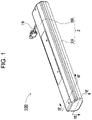
FIG. 1 is a perspective view of a battery pack according to an exemplary embodiment of the present invention. -
FIG. 2 is an exploded perspective view of the battery pack illustrated inFIG. 1 . -
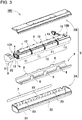
FIG. 3 is an exploded perspective view of the battery pack illustrated inFIG. 2 . -
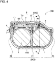
FIG. 4 is a sectional view of the battery pack along line IV-IV illustrated inFIG. 1 . -
FIG. 5 is a cross-sectional view of the battery pack along line V-V illustrated inFIG. 4 . -
FIG. 6 is a cross-sectional view of the battery pack along line VI-VI illustrated inFIG. 1 . -
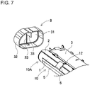
FIG. 7 is an exploded perspective view of the battery pack for illustrating a heat-resistant cap and a battery block. - A battery pack according to a first exemplary embodiment of the present invention includes a battery block including battery cells arranged in plural rows, a heat-resistant cap coupled to an end of the battery block, and a battery case accommodating the battery block and having an exhaust opening. Each battery cell includes a discharge valve provided on an end surface thereof. The discharge valve is configured to open when an internal pressure of the cell exceeds a predetermined pressure. The exhaust opening is configured to discharge exhaust gas from the discharge valve to an outside of the case. A valve-side end surface of each battery cell provided with the discharge valve is arranged at a first end of the battery block to which the heat-resistant cap is coupled. The heat-resistant cap includes a closing plate providing a first discharge gap between the closing plate and an end surface of the battery block, a peripheral wall coupled to a periphery of the closing plate and providing a second discharge gap between the peripheral wall and an outer circumference of the battery block, and a partition wall provided on an end surface of the closing plate facing the battery block and between end surfaces of adjacent battery cells. The partition wall partitions the first discharge gap into portions at the end surfaces of the adjacent battery cells. The exhaust gas discharged to the valve-side end surface of the battery cell is configured to pass through a discharge gap including the first discharge gap and the second discharge gap and to be exhausted from the exhaust opening to an outside.
- The battery pack described above eliminates adverse effects caused by high-temperature exhaust gas ejected from the opening discharge valve and ensures high safety. This is because the battery pack described above causes the high-temperature exhaust gas ejected from the discharge valve to collide with the heat-resistant cap to reduce energy and to control the flow direction of the discharged gas. This feature is provided because of the following configure of the battery pack described above. The first end of the battery block including the battery cells arranged in plural rows is used as the valve-side end surface of each battery cell including the discharge valve. The heat-resistant cap is coupled to the end, the closing plate provided with the first discharge gap between the closing plate and an end surface of the battery block is arranged on this heat-resistant cap. The peripheral wall is provided on a periphery of the closing plate. The second discharge gap is provided between the peripheral wall and the outer circumference of the battery block. The partition wall is further provided between end surfaces of adjacent battery cells on the end surface of the closing plate facing the battery block. The partition wall partitions the second discharge gap into portions at the end surfaces of the battery cells. The exhaust gas discharged to the valve-side end surface of the battery cell is discharged through the first discharge gap and the second discharge gap. In the battery pack described above, in the case where a particular battery cell arranged at an end of the battery block undergoes thermal runaway and ejects high-temperature exhaust gas, the exhaust gas discharged from the end surface is ejected to the first discharge gap partitioned by the partition wall and guided to the second discharge gap. The heat-resistant cap guides the high-temperature exhaust gas from the first discharge gap to the second discharge gap to attenuate and exhaust the energy, but does not cause the exhaust gas to flow to the end surface of the adjacent battery cell that has not undergone thermal runaway. In particular, the exhaust gas having a high temperature exceeding 400°C immediately after being ejected is discharged to the outside without flowing to the end surface of the adjacent battery cell that has not undergone thermal runaway. Thus, both the energy of motion and the thermal energy of the exhaust gas are reduced and discharged to the outside while the induction of thermal runaway of the battery cell is prevented.
- In the battery pack described above, the heat-resistant cap coupled to the battery block prevents the induction of thermal runaway, and reduces the energy of the exhaust gas and discharges it to the outside, so that the feature that the assembly is simple and the mass production can be performed efficiently is also achieved.
- In a battery pack according to a second exemplary embodiment of the present invention, the battery block includes a battery holder positioning the battery cells at predetermined positions. The second discharge gap is provided between the peripheral wall and the battery holder.
- In a battery pack according to a third exemplary embodiment of the present invention, the battery holder and the battery case are made of plastic. The heat-resistant cap is made of plastic having a higher heat resistance temperature than the battery holder and the battery case. The closing plate, the peripheral wall, and the partition wall are unitarily molded from plastic.
- In a battery pack according to a fourth exemplary embodiment of the present invention, the heat-resistant cap is made of fiber-reinforced plastic reinforced with heat-resistant fibers.
- In a battery pack according to a fifth exemplary embodiment of the present invention, the heat-resistant fibers are inorganic fibers.
- In a battery pack according to a sixth exemplary embodiment of the present invention, the battery block further includes a lead plate provided at an end surface of the first end thereof. The lead plate connects adjacent battery cells to each other. A leading edge of the partition wall contacts a surface of the lead plate.
- In a battery pack according to a seventh exemplary embodiment of the present invention, the battery cells are cylindrical batteries. In a battery pack according to an eighth exemplary embodiment of the present invention, the partition wall is arranged in a valley formed on outer peripheries of adjacent cylindrical batteries.
- In a battery pack according to a ninth exemplary embodiment of the present invention, the battery cells are non-aqueous electrolyte secondary batteries. In a battery pack according to a tenth exemplary embodiment of the present invention, the battery cells are lithium ion batteries.
- Hereinafter, exemplary embodiments of the present invention will be described in detail with reference to the drawings. Note that, in the following description, terms (for example, "top", "bottom", and other terms including those terms) indicating specific directions or positions are used as necessary; however, the use of those terms is for facilitating the understanding of the invention with reference to the drawings, and the technical scope of the present invention is not limited by the meanings of the terms. Parts denoted by the same reference numerals in a plurality of drawings indicate the identical or equivalent parts or members.
- Further, the following exemplary embodiment illustrates specific examples of the technical concept of the present invention, and the present invention is not limited by the following exemplary embodiment. In addition, unless otherwise specified, dimensions, materials, shapes, relative arrangements, and the like of the constituent elements described below are not intended to limit the scope of the present invention, but are intended to be illustrative. Further, the contents described in one exemplary embodiment and one working example are also applicable to other exemplary embodiments and working examples. The sizes, positional relationships, and the like of members illustrated in the drawings may be exaggerated in order to clarify description.
- In
battery pack 100 illustrated inFIGS. 1 to 6 ,battery block 10 includingbattery cells 1 arranged in plural rows is accommodated inbattery case 2.Battery case 2 includeslower case 2A that is a first case andupper case 2B that is a second case coupled to the first case and closing an opening of the first case. Inbattery block 10 shone inFIGS. 2 to 5 ,battery cells 1 are arranged in two rows and four stages on the same plane. Inbattery block 10, two rows ofbattery cells 1 are arranged at predetermined positions bybattery holder 4 to formbattery assembly 11.Plural battery assemblies 11 are arranged and coupled in multiple stages in a longitudinal direction. Heat-resistant cap 8 is coupled to an end ofbattery block 10. Heat-resistant cap 8 reduces energy by controlling a flow direction of high-temperature exhaust gas ejected from the discharge valve ofbattery cell 1, and further, guides the exhaust gas to an exhaust opening to safely discharge the exhaust gas to an outside ofbattery case 2. -
Battery cell 1 is a cylindrical battery in which a discharge valve is provided on a valve-side end surface 1a of the cell. The discharge valve is configured to open when an internal pressure of the cell exceeds a predetermined pressure. In the cylindrical battery, an electrode and an electrolytic solution are accommodated in a cylindrical metal case. The metal case has a sealed structure in which a sealing plate is hermetically fixed to an opening of a cylindrical package can with a closed bottom. The package can is fabricated by pressing a metal plate into a cylindrical shape. The sealing plate is caulked and hermetically fixed to a peripheral edge of the opening of the package can with a packing made of insulating material interposed between the sealing plate and the package. - Although not illustrated, in order to prevent
battery cell 1 from damage due to an abnormally high internal pressure of the metal case, the discharge valve is provided on the sealing plate, and the sealing plate is thus valve-side end surface 1a. Inbattery cell 1, an opening of the discharge valve that opens and discharges internal gas or the like is provided in a sealing plate. However, inbattery cell 1, the opening of the discharge valve is not necessarily provided in the sealing plate of the exterior can, and the discharge valve and the opening thereof may be provided in the bottom portion that is the end surface opposite to the sealing plate to function the bottom portion as the valve-side end surface. The discharge valve is configured to open when the internal pressure rises higher than a predetermined pressure, for example, 1.5 MPa, and prevents such a breakage of the metal case due to the increase of the internal pressure. For example, whenbattery cell 1 is in an abnormal state due to internal short-circuit, the discharge valve opens to prevent rupture. In this state, since the temperature ofbattery cell 1 is also very high, the gas and the electrolytic solution (ejected matter) discharged from the opened discharge valve has abnormally high temperature. In particular, in a battery pack in whichbattery cell 1 is a non-aqueous electrolyte secondary battery, such as a lithium ion battery, the temperature of the exhaust gas becomes an abnormally high temperature higher than 400°C. Furthermore, since the lithium ion battery is filled with a non-aqueous electrolytic solution, when the electrolytic solution is discharged to the outside of the case at a high temperature, the electrolytic solution may contact oxygen in the air and ignited, and may have an abnormally higher temperature. In not only the lithium ion battery but also other batteries, since the discharge valve opens in an abnormal state, the exhaust gas ejected from the discharge valve has an abnormally high temperature. Therefore, the energy of the exhaust gas is ejected from the opening discharge valve is reduced and discharged to the outside of the case in order to maintain high safety. - In
battery block 10 illustrated inFIGS. 2 to 6 , heat-resistant cap 8 is coupled tofirst end 10A, one end ofbattery block 10. Inbattery block 10, valve-side end surface 1a ofbattery cell 1 is arranged atfirst end 10A. Inbattery block 10 includingbattery cells 1 arranged in plural rows, valve-side end surfaces 1a of allbattery cells 1 are arranged atfirst end 10A, or valve-side end surface 1a of any one ofbattery cells 1 is arranged atfirst end 10A, and the exhaust gas is ejected fromfirst end 10A ofbattery block 10.Battery block 10 shown inFIG. 3 couples battery assemblies 11 in the longitudinal direction. Inbattery block 10,exhaust gap 12 through which the exhaust gas is discharged is provided betweenbattery assemblies 11. Inbattery block 10 shown inFIG. 3 , fourbattery assemblies 11 are coupled in the longitudinal direction, so that three rows ofexhaust gaps 12 are provided. Eachexhaust gap 12 is arranged betweenadjacent battery assemblies 11, and disperses and exhausts the exhaust gas discharged frombattery cells 1 of each ofbattery assemblies 11 to the surroundings. - In
battery assembly 11,battery cells 1 are arranged in two rows at predetermined positions inbattery holder 4.Battery holder 4 is molded from thermoplastic plastic material into a shape in whichbattery cells 1 are fitted and arranged at the predetermined positions. For the plastic ofbattery holder 4, an engineering plastic, such as polycarbonate, having excellent heat insulating properties, is suitable. Inbattery holder 4 shown inFIG. 3 ,battery cells 1 are arranged in two rows in a form extending in a longitudinal direction ofbattery case 2. Inbattery block 10 in the drawings,battery assemblies 11 are coupled in four stages by providingexhaust gaps 12 for exhaust gas between the assemblies.Battery block 10 connectsbattery cells 1 in series or in parallel with a lead plate (not illustrated) arranged inexhaust gap 12. Inbattery block 10 in the drawings,battery assemblies 11 including two rows ofbattery cells 1 in the longitudinal direction are arranged in four stages, and eightbattery cells 1 in two rows and four stages are connected in series and in parallel. Inbattery pack 100 in the drawings,battery block 10 in whichbattery assemblies 11 each including the two rows ofbattery cells 1 are coupled in four stages is arranged inbattery case 2, but the battery pack of the present invention does not specify the number or connection ofbattery cells 1 accommodated in the case to the structure shown in the drawings. -
Exhaust gap 12 is a gap configured to guide the exhaust gas ejected from the discharge valve to the outside and connectsbattery cells 1 ofbattery assemblies 11 bylead plate 13.Exhaust gap 12 has a width ranging, for example, 1 mm to 5 mm, and diffuses and discharges the exhaust gas ejected from the discharge valve at the end surface ofbattery cell 1 to the surroundings. -
Battery case 2 is made of thermoplastic plastic, such as polycarbonate, has an elongated box shape as a whole, and accommodatesbattery block 10 andcircuit board 3 connected tobattery block 10. Polycarbonate used forbattery case 2 andbattery holder 4 is durable from a low temperature to a high temperature and is excellent in impact resistance. However, the present invention does not specifybattery holder 4 andbattery case 2 as polycarbonate, and other thermoplastic resins that can be used in a wide temperature range, preferably engineering plastics, can also be used. -
Battery case 2 shown inFIGS. 1 to 4 includeslower case 2A andupper case 2B that closes an opening oflower case 2A.Lower case 2A has a gutter shape withside walls 22 provided on both sides ofbottom plate 21 having an elongated rectangular shape in the drawings.Battery block 10 is arranged betweenside walls 22.Upper case 2B has an outer peripheral edge coupled tolower case 2A to close an upper opening oflower case 2A. Inlower case 2A illustrated inFIG. 4 ,side walls 22 on both sides are formed into a curved shape along the cylindrical battery. Inlower case 2A,plural exhaust openings 23 for exhausting the exhaust gas to the outside are provided in ofside walls 22 apart from each other in the longitudinal direction ofside walls 22. Inbattery pack 100 in the drawings,heat dissipation plate 5 is disposed betweenbattery block 10 andlower case 2A.Exhaust openings 23 open at positions facingheat dissipation plate 5, that is, outsideheat dissipation plate 5. Inbattery pack 100, the exhaust gas ejected toexhaust gap 12 is discharged to the outside while having the energy reduced byheat dissipation plate 5. The exhaust gas passes through a gap provided betweenbattery block 10 andheat dissipation plate 5, and further passes through a gap betweenheat dissipation plate 5 andbattery case 2, and is discharged fromexhaust opening 23 to the outside. Inbattery pack 100 havingheat dissipation plate 5, the energy of the exhaust gas is reduced and discharged byheat dissipation plate 5, so that higher safety can be secured. However, in the battery pack of the present invention, the exhaust gas may be guided from the gap in the case to exhaust opening 23 and discharged without necessarily arrangingheat dissipation plate 5. - In
battery pack 100 shown inFIGS. 2 and3 , heat-resistant cap 8 is coupled tobattery block 10 in order to reduce and discharge the energy of the exhaust gas ejected tofirst end 10A ofbattery block 10. Inbattery pack 100 in the drawings, heat-resistant cap 8 is coupled tofirst end 10A ofbattery block 10. An end surface plate (not illustrated) unitarily molded withbattery holder 4 is arranged atsecond end 10B from which leadwire 19 is drawn. Although not illustrated, the end surface plate has a structure in which a heat insulating plate is arranged inside or a diffusion gap that diffuses the exhaust gas is provided to prevent heat damage due to the high-temperature exhaust gas. However, although not illustrated,battery block 10 may have a heat resistant structure by coupling heat-resistant cap 8 to both ends, orbattery cell 1 may be arranged such that valve-side end surface 1a ofbattery cell 1 is not arranged on an end surface ofbattery block 10 to which heat-resistant cap 8 is not coupled. - Heat-
resistant cap 8 is produced by molding thermoplastic plastic having more excellent heat resistance characteristics thanbattery holder 4 andbattery case 2. For example, a fiber-reinforced plastic in which inorganic fibers are embedded and reinforced, such as PBT, is molded and produced as a plastic excellent in heat resistance characteristics. Heat-resistant cap 8 is coupled to the end ofbattery block 10, reduces the energy of the exhaust gas ejected from valve-side end surface 1a ofbattery cell 1, and changes the flow direction. Heat-resistant cap 8 illustrated inFIGS. 2 to 7 includes closingplate 31 facingend surface 10a of the battery block,peripheral wall 32 coupled to a periphery of closingplate 31, andpartition wall 33 provided on a surface of closingplate 31 facingend surface 10a of the battery block. Closingplate 31,peripheral wall 32, andpartition wall 33 are unitarily molded. - Closing
plate 31 providesfirst discharge gap 15A between the closing plate and endsurface 10a of the battery block to discharge the exhaust gas ejected from the discharge valve. Closingplate 31 causes the exhaust gas ejected from the discharge valve to collide with an inner surface of the closing plate infirst discharge gap 15A to reduce the energy of the gas, and further diffuses the energy to the surroundings.First discharge gap 15A provided betweenclosing plate 31 and batteryblock end surface 10a, more precisely, between closingplate 31 and the end surface ofbattery cell 1 has a width, for example, equal to or larger than 0.5 mm and equal to or less than 3 mm so as to reduce the energy of motion of the exhaust gas while smoothly discharging the exhaust gas. - The exhaust gas passing through
first discharge gap 15A is diffused to the surroundings by closingplate 31 and collides with an inner side ofperipheral wall 32. Leadplate 13 fixed tobattery cell 1 is arranged infirst discharge gap 15A. Leadplate 13 is welded and fixed to the end surface ofbattery cell 1. Leadplate 13 includes a welded portion across a slit provided in a center portion of the lead plate. The welded portion is welded to an end surface ofbattery cell 1. Since an outer peripheral portion of the lead plate outside the welded portion across the slit is not welded to the end surface ofbattery cell 1, a slight gap is formed by the lead plate without adhering to the end surface ofbattery cell 1. Therefore,first discharge gap 15A is provided betweenclosing plate 31 andlead plate 13 and betweenlead plate 13 and the end surface of the battery cell. The total width of first discharge gap 15Aformed on both surfaces oflead plate 13 is preferably determined to the above-described range such that the energy of the motion of the exhaust gas may be reduced by allowing the exhaust gas to pass through the narrow gap while smoothly discharging the exhaust gas. -
Peripheral wall 32 providessecond discharge gap 15B betweenperipheral wall 32 and the outer circumference ofbattery block 10 in order to redirect and discharge the exhaust gas flowing in fromfirst discharge gap 15A.Peripheral wall 32 illustrated inFIG. 5 causes the exhaust gas flowing in fromfirst discharge gap 15A to collide with the inner side of the peripheral wall to reduce the energy, and changes the flow direction perpendicularly without further scattering the exhaust gas to the surroundings to change the flow direction to the longitudinal direction ofbattery cell 1. The exhaust gas collides with the inner surface ofperipheral wall 32, changes the direction, reduces the energy of the motion, and is discharged in the longitudinal direction ofbattery cell 1.Peripheral wall 32 providessecond discharge gap 15B between the peripheral wall and the outer circumference surface ofbattery cell 1 in order to allow the exhaust gas to flow between the peripheral wall andbattery cell 1. The exhaust gas that has collided with the inner side of closingplate 31 and has flown intosecond discharge gap 15B is redirected insidepartition wall 33 as indicated by an arrow in the drawings and is discharged in the longitudinal direction ofbattery cell 1. -
Partition wall 33 inFIG. 6 is fixed perpendicularly to the inner surface of closingplate 31 topartition discharge gap 15 between the closing plate and the end surface ofbattery cell 1.Partition wall 33 separates divideddischarge gap 15a provided betweenclosing plate 31 and valve-side end surface 1a ofabnormal battery cell 1 with the opening discharge valve from divideddischarge gap 15a between closingplate 31 andadjacent battery cell 1. Whenbattery cell 1 thermally runs away due to, for example, an internal short circuit or the like, the internal pressure of the cell abnormally rises and the discharge valve opens. In this state, the exhaust gas ejected from the discharge valve has an abnormal high temperature. The high-temperature exhaust gas heatsadjacent battery cell 1, and induces thermal runaway of the adjacent battery cell.Partition wall 33 prevents the high-temperature exhaust gas from flowing to the end surface ofadjacent battery cell 1 to prevent induction of thermal runaway. Sincepartition wall 33 is provided to prevent the exhaust gas ejected fromabnormal battery cell 1 from heatingadjacent battery cell 1,discharge gap 15 partitions betweenbattery cells 1. - In heat-
resistant cap 8 shown inFIG. 4 ,second discharge gap 15B is wider on the upper part thereof than on the lower part thereof in the drawing, and a larger amount of exhaust gas is exhausted on the upper part than the lower part. On the upper part ofsecond discharge gap 15B,fitting groove 4a is provided inbattery holder 4, andpartition wall 33 is guided to fitting intogroove 4a to arrangepartition wall 33 at a predetermined position. -
Partition wall 33 prevents the ejected exhaust gas from flowing to the end surface ofadjacent battery cell 1, and prevents the exhaust gas from heatingadjacent battery cell 1.Partition wall 33 protrudes from closingplate 31 tofirst discharge gap 15A, and is arranged between the respective end surfaces of the battery cells. In heat-resistant cap 8 shown inFIG. 5 ,partition wall 33 is provided not only infirst discharge gap 15A but also insecond discharge gap 15B, andpartition wall 33 offirst discharge gap 15A andsecond discharge gap 15B has a single plate shape. Heat-resistant cap 8 can more effectively prevent the high-temperature exhaust gas from heatingadjacent battery cell 1, and can more effectively prevents a thermal failure ofadjacent battery cell 1. However, the partition wall may be provided only infirst discharge gap 15A to prevent the exhaust gas from heating the end surface ofadjacent battery cell 1 at the end surface ofbattery block 10. - In heat-
resistant cap 8 shown inFIGS. 5 and7 , a center portion ofpartition wall 33 disposed infirst discharge gap 15A is lower than both ends ofpartition wall 33 which are raised to extend tosecond discharge gap 15B.Partition wall 33 protruding from the inner surface of closingplate 31 contacts a surface oflead plate 13 to dividefirst discharge gap 15A betweenbattery cells 1, and both ends ofpartition wall 33 extend into a valley on between the outer circumferences of the cylindrical batteries to divide, betweenbattery cells 1,second discharge gap 15B provided betweenbattery cell 1 andperipheral wall 32. In heat-resistant cap 8 shown inFIG. 4 ,second discharge gap 15B on the upper side ofbattery cell 1 is wider than that in the lower side in the drawings, and thus a vertical width ofpartition wall 33 on the upper side is larger than that of the lower side, so as to guide a lower edge ofpartition wall 33 on the upper side tofitting groove 4a provided inbattery holder 4. The structure in whichpartition wall 33 is guided tofitting groove 4a ofbattery holder 4 prevents a positional displacement ofpartition wall 33 whilesecond discharge gap 15B is partitioned so as to more reliably prevent the exhaust gas from leaking, and the heating ofadjacent battery cell 1 by the exhaust gas can be more reliably suppressed. -
Battery pack 100 shown inFIGS. 2 and3 further includesheat dissipation plate 5 in order to more effectively reduce the energy of the exhaust gas.Heat dissipation plate 5 is arranged insidelower case 2A and betweenlower case 2A andbattery block 10, and reduces energy of exhaust gas ejected frombattery cell 1.Heat dissipation plate 5 may be preferably made of a plate material having more thermal conduction characteristics thanbattery case 2.Heat dissipation plate 5 absorbs thermal energy of the colliding exhaust gas, and quickly diffuses the absorbed thermal energy over a wide area to conduct the thermal energy tolower case 2A, andlower case 2A dissipates the thermal energy to the outside over a wide area. - As a plate member having preferable thermal conduction characteristics, a metal plate is used for
heat dissipation plate 5. Aluminum (including an aluminum alloy) plate is suitable forheat dissipation plate 5. Since the aluminum plate has heat resistance and excellent thermal conduction characteristics and is light, the thermal energy of the exhaust gas may be quickly diffused and efficiently dissipated althoughheat dissipation plate 5 is reduced in weight. Inbattery pack 100 in the drawings,side walls 22 oflower case 2A are extended along an outer peripheral surface of the cylindrical battery, andheat dissipation plate 5 is arranged betweenside wall 22 andbattery block 10. Inheat dissipation plate 5 arranged here, a portion ofheat dissipation plate 5 arranged on an inner surface ofbottom plate 21 oflower case 2A has a planar shape while a portion ofheat dissipation plate 5 arranged on eachside wall 22 has a curved shape extended along an outer surface of the cylindrical battery.Battery block 10 is arranged insideheat dissipation plate 5, andbattery cell 1 is arranged at a predetermined position inbattery holder 4 inbattery block 10. Therefore,battery assembly 11 ofbattery block 10 is arranged insideheat dissipation plate 5. A side wall portion of the heat dissipation plate that is curved inward has a height that is about half the thickness ofbattery block 10 such thatbattery block 10 may be smoothly guided and arranged at a predetermined position, and inner surfaces of the side wall portions may contact both side surfaces ofbattery block 10. The side wall portions of the heat dissipation plate contacting both side surfaces ofcurved battery block 10 facilitate the heat conduction frombattery block 10 efficiently. However, if an air layer is formed between the side wall portion andbattery block 10, the air layer inhibits heat conduction. This is because, the curved side wall portion of the heat dissipation plate which is higher than half the thickness ofbattery block 10 causes an opening width of an upper edge ofheat dissipation plate 5 to be narrower than a lateral width ofbattery block 10, and causesbattery block 10 to hardly be inserted smoothly. -
Heat dissipation plate 5 efficiently absorbs the thermal energy ofbattery block 10 by bringing the inner surfaces of the side wall portions of the heat dissipation plate in surface contact with curved surfaces on both sides ofbattery block 10 and bringing a bottom surface portion into surface contact with a bottom surface ofbattery block 10. Furthermore,heat dissipation plate 5 efficiently thermally conducts the absorbed thermal energy tolower case 2A by bringing an outer surface in surface contact with an inner surface oflower case 2A. Asheat dissipation plate 5, an aluminum plate is used as a metal plate having excellent thermal conduction characteristics, but a metal plate other than aluminum, for example, a copper plate, or another plate member having heat resistance and excellent thermal conduction characteristics may also be used. - Heat-
resistant cover 6 is arranged on a side edge ofheat dissipation plate 5 at a position covering an opening ofexhaust gap 12 betweenbattery assemblies 11. A metal plate made of aluminum or the like having excellent heat resistance and thermal conduction characteristics is suitable for heat-resistant cover 6, as forheat dissipation plate 5. Inbattery pack 100 shown inFIGS. 2 and3 ,heat dissipation plate 5 and heat-resistant cover 6 are made unitarily of a single metal plate. This structure allows heat-resistant cover 6 to be accurately arranged viaheat dissipation plate 5. Heat-resistant cover 6 is made of a bendable metal plate since heat-resistant cover 6 is bent to close the opening ofexhaust gap 12 withbattery block 10 being arranged inside. Heat-resistant cover 6 andheat dissipation plate 5 made unitarily of a single metal plate allows heat-resistant cover 6 to be bendable, and to be arranged at an ideal position on the opening ofexhaust gap 12 ofbattery block 10 so as not to be displaced. - Heat-
resistant cover 6 has a lateral width wider thanexhaust gap 12 so as to sufficiently cover the opening ofexhaust gap 12. The lateral width of heat-resistant cover 6 is larger than that of heat-resistant cover 6 by a difference, for example, equal to or larger than 1 mm , preferably equal to or larger than 2 mm, and more preferably equal to or larger than 3 mm. Heat-resistant cover 6 with an excessively large width hardly bent along the surface of the cylindrical battery to closeexhaust gap 12 in an ideal state, so that the lateral width of the heat-resistant cover 6 is, for example, equal to or less than 20 mm, preferably equal to or less than 15 mm. Inbattery pack 100 shown inFIG. 3 , since fourbattery assemblies 11 are coupled to one another,exhaust gaps 12 arranged betweenrespective battery assemblies 11 are in three rows. Since heat-resistant cover 6 closes the opening of eachexhaust gap 12, three rows of heat-resistant covers 6 are provided alongexhaust gaps 12 on the side edge ofheat dissipation plate 5 shown inFIG. 3 . That is, plural heat-resistant covers 6 that independently closesrespective exhaust gaps 12 are provided. - Heat-
resistant cover 6 may be lengthened to widen the closed region of the opening ofexhaust gap 12. Inbattery pack 100 shown inFIG. 3 ,circuit board 3 is arranged on an upper surface ofbattery block 10, heat-resistant cover 6 has a length to allow a leading edge of heat-resistant cover 6 to be close to both side edges ofcircuit board 3, and both heat-resistant cover 6 andcircuit board 3 cover the opening ofexhaust gap 12.Circuit board 3 is made of thermosetting resin, such as glass epoxy, and has more excellent heat resistance thanbattery case 2 made of thermoplastic resin. Inbattery pack 100 having this structure, almost the entire circumference of the opening ofexhaust gap 12 is covered withheat dissipation plate 5, heat-resistant cover 6, andcircuit board 3 having more excellent heat resistance characteristics thanbattery case 2. When a wide gap is provided between heat-resistant cover 6 andcircuit board 3, the exhaust gas passes through the gap, and thus the gap is as narrow as possible, for example, 2 mm or less, preferably 1 mm or less, to suppress the passage of the exhaust gas. - An electronic component (not illustrated) connected to
battery cells 1 to constitute a protection circuit forbattery cells 1 is mounted ontocircuit board 3. The protection circuit is a circuit that prevents overcharge and overdischarge ofbattery cells 1, a circuit that prevents overcurrent, or a circuit that interrupts current in a state in which the temperature rises abnormally. -
Battery pack 100 as described above causes the exhaust gas ejected from the discharge valve to collide with heat-resistant cap 8,heat dissipation plate 5, heat-resistant cover 6, andcircuit board 3 to reduce the energy of the gas, and to further diffuse and be discharged fromexhaust opening 23 provided inlower case 2A to the outside of the case.Exhaust opening 23 is arranged at a position facingheat dissipation plate 5 so as to cause the exhaust gas to collide withheat dissipation plate 5 and heat-resistant cover 6 to reduce and diffuse the energy of the gas, and then, the exhaust gas is discharged to the outside ofbattery case 2.Exhaust opening 23 arranged at the position facingheat dissipation plate 5, withheat dissipation plate 5 inside, discharges the gas diffused byheat dissipation plate 5 fromexhaust opening 23 to the outside ofbattery case 2. Inlower case 2A shown inFIGS. 2 and3 ,plural exhaust openings 23 are arranged inside wall 22 oflower case 2A and separated away from each other in the longitudinal direction.Battery pack 100 causes the exhaust gas ejected toexhaust gap 12 to diffuse by colliding withheat dissipation plate 5 and heat-resistant cover 6, and causes the diffused exhaust gas to flow intogap 14 in the case to be exhausted fromexhaust opening 23 to the outside ofbattery case 2.Lower case 2A is attached withlabel 7 peeled off or melted by the exhaust gas so as to close the opening ofexhaust opening 23. Inbattery pack 100,exhaust opening 23 may be closed bylabel 7 to prevent foreign substances from entering. - The present invention may be effectively used for a battery pack configured to safely discharge exhaust gas.
-
- 100
- battery pack
- 1
- battery cell
- 1a
- valve-side end surface
- 2
- battery case
- 2A
- lower case
- 2B
- upper case
- 3
- circuit board
- 4
- battery holder
- 4a
- fitting groove
- 5
- heat dissipation plate
- 6
- heat-resistant cover
- 7
- label
- 8
- heat-resistant cap
- 10
- battery block
- 10A
- first end
- 10a
- battery block end surface
- 10B
- second end
- 11
- battery assembly
- 12
- exhaust gap
- 13
- lead plate
- 14
- gap
- 15
- discharge gap
- 15A
- first discharge gap
- 15a
- divided discharge gap
- 15B
- second discharge gap
- 19
- lead wire
- 21
- bottom plate
- 22
- side wall
- 23
- exhaust opening
- 31
- closing plate
- 32
- peripheral wall
- 33
- partition wall
Claims (10)
- A battery pack comprising:a battery block including a plurality of battery cells arranged in a plurality of rows, each of the plurality of battery cells including a discharge valve provided at an end of the each of the plurality of battery cells, the discharge valve being configured to open when an internal pressure of the each of the plurality of battery cells exceeds a predetermined pressure;a heat-resistant cap coupled to an end of the battery block; anda battery case accommodating the battery block therein, the battery case having an exhaust opening configured to discharge exhaust gas from the discharge valve to an outside of the case, whereina valve-side end surface of the each of the plurality of battery cells at which the discharge valve of the each of the plurality of battery cells is disposed at a first end of the battery block to which the heat-resistant cap is coupled,the heat-resistant cap includes:a closing plate providing a first discharge gap between the closing plate and the battery block end surface;a peripheral wall coupled to a periphery of the closing plate, the peripheral wall providing a second discharge gap between the peripheral wall and an outer circumference of the battery block; anda partition wall provided on a surface of the closing plate facing an end of the battery block and between respective end surfaces of adjacent battery cells out of the plurality of battery cells, the partition wall partitioning the first discharge gap into portions on the respective end surfaces of adjacent battery cells, andthe first discharge gap and the second discharge gap constitutes a discharge gap configured to allow the exhaust gas discharged to the valve-side end surface of the each of the battery cells to pass through the discharge gap and be discharged from the exhaust opening to an outside of the battery pack.
- The battery pack according to claim 1, whereinthe battery block further includes a battery holder positioning the plurality of battery cells at predetermined positions, andthe second discharge gap is provided between the peripheral wall and the battery holder.
- The battery pack according to claim 2, whereinthe battery holder and the battery case are made of plastic, andthe heat-resistant cap is made of plastic having a higher heat resistance temperature than the battery holder and the battery case, andthe closing plate, the peripheral wall, and the partition wall are unitarily molded with plastic.
- The battery pack according to claim 3, wherein the heat-resistant cap is made of fiber-reinforced plastic reinforced with heat-resistant fibers.
- The battery pack according to claim 4, wherein the heat-resistant fibers are inorganic fibers.
- The battery pack according to any one of claims 1 to 5, whereinthe battery block further includes a lead plate provided at an end surface of the first end of the battery block, the lead plate connecting the adjacent battery cells to each other, anda leading edge of the partition wall contacts a surface of the lead plate.
- The battery pack according to any one of claims 1 to 6, wherein the plurality of battery cells are a plurality of cylindrical batteries.
- The battery pack according to claim 7, wherein the partition wall is arranged in a valley formed on outer peripheries of adjacent cylindrical batteries out of the plurality of cylindrical batteries.
- The battery pack according to any one of claims 1 to 8, wherein the plurality of battery cells are non-aqueous electrolyte secondary batteries.
- The battery pack according to claim 9, wherein the plurality of battery cells are lithium ion batteries.
Applications Claiming Priority (2)
| Application Number | Priority Date | Filing Date | Title |
|---|---|---|---|
| JP2019142581 | 2019-08-01 | ||
| PCT/JP2020/028646 WO2021020329A1 (en) | 2019-08-01 | 2020-07-27 | Pack battery |
Publications (2)
| Publication Number | Publication Date |
|---|---|
| EP4009425A1 true EP4009425A1 (en) | 2022-06-08 |
| EP4009425A4 EP4009425A4 (en) | 2022-10-19 |
Family
ID=74229132
Family Applications (1)
| Application Number | Title | Priority Date | Filing Date |
|---|---|---|---|
| EP20846002.2A Pending EP4009425A4 (en) | 2019-08-01 | 2020-07-27 | Pack battery |
Country Status (5)
| Country | Link |
|---|---|
| US (1) | US20220271391A1 (en) |
| EP (1) | EP4009425A4 (en) |
| JP (1) | JPWO2021020329A1 (en) |
| CN (1) | CN114072963A (en) |
| WO (1) | WO2021020329A1 (en) |
Families Citing this family (1)
| Publication number | Priority date | Publication date | Assignee | Title |
|---|---|---|---|---|
| CN113067077B (en) * | 2021-03-27 | 2022-06-14 | 安徽相成新能源科技有限公司 | Power battery thermal management system |
Family Cites Families (14)
| Publication number | Priority date | Publication date | Assignee | Title |
|---|---|---|---|---|
| JP2001023587A (en) * | 1999-07-07 | 2001-01-26 | Sanyo Electric Co Ltd | Electric razor |
| JP2001266818A (en) * | 2000-03-23 | 2001-09-28 | Sanyo Electric Co Ltd | Battery pack |
| JP3848565B2 (en) * | 2001-11-27 | 2006-11-22 | 松下電器産業株式会社 | Battery connection structure, battery module, and battery pack |
| JP4810797B2 (en) * | 2004-05-06 | 2011-11-09 | トヨタ自動車株式会社 | Battery module and battery pack |
| JP4518958B2 (en) * | 2005-01-07 | 2010-08-04 | 三洋電機株式会社 | Battery module |
| JP2007012485A (en) * | 2005-06-30 | 2007-01-18 | Sanyo Electric Co Ltd | Battery with cap and power supply device |
| EP2022111A2 (en) * | 2006-04-28 | 2009-02-11 | Johnson Controls Technology Company | Battery module assembly |
| JP4358245B2 (en) * | 2007-03-09 | 2009-11-04 | レノボ・シンガポール・プライベート・リミテッド | Battery pack and portable electronic device |
| JP2009211909A (en) * | 2008-03-04 | 2009-09-17 | Panasonic Corp | Battery, battery pack, and method of manufacturing connection terminals used therefor |
| CN102017230B (en) * | 2008-04-25 | 2013-10-16 | 松下电器产业株式会社 | Lead storage battery |
| JP2012204296A (en) * | 2011-03-28 | 2012-10-22 | Gs Yuasa Corp | Battery pack, single battery, and cap |
| JP2014170613A (en) * | 2011-06-28 | 2014-09-18 | Panasonic Corp | Battery module |
| JP5903607B2 (en) * | 2011-11-11 | 2016-04-13 | パナソニックIpマネジメント株式会社 | Battery pack |
| US10903465B2 (en) * | 2016-06-30 | 2021-01-26 | Sanyo Electric Co., Ltd. | Battery block |
-
2020
- 2020-07-27 JP JP2021535320A patent/JPWO2021020329A1/ja active Pending
- 2020-07-27 CN CN202080046831.6A patent/CN114072963A/en active Pending
- 2020-07-27 WO PCT/JP2020/028646 patent/WO2021020329A1/en unknown
- 2020-07-27 US US17/630,761 patent/US20220271391A1/en active Pending
- 2020-07-27 EP EP20846002.2A patent/EP4009425A4/en active Pending
Also Published As
| Publication number | Publication date |
|---|---|
| WO2021020329A1 (en) | 2021-02-04 |
| CN114072963A (en) | 2022-02-18 |
| US20220271391A1 (en) | 2022-08-25 |
| EP4009425A4 (en) | 2022-10-19 |
| JPWO2021020329A1 (en) | 2021-02-04 |
Similar Documents
| Publication | Publication Date | Title |
|---|---|---|
| JP7418410B2 (en) | battery module | |
| JP7418405B2 (en) | battery module | |
| CN213782158U (en) | Battery, device comprising battery and equipment for preparing battery | |
| EP3540815B1 (en) | Battery module | |
| EP3916834A1 (en) | Battery pack | |
| JP7401467B2 (en) | pack batteries | |
| CN114175377A (en) | Battery and related device, preparation method and preparation equipment thereof | |
| WO2020188949A1 (en) | Battery module | |
| EP3916866A1 (en) | Battery pack | |
| EP4007007A1 (en) | Battery pack | |
| JP2020161210A (en) | Power supply device | |
| JP7418409B2 (en) | battery module | |
| KR20220078641A (en) | Battery packs and transportation equipment | |
| EP4009425A1 (en) | Pack battery | |
| EP4007047A1 (en) | Battery pack | |
| EP4009424A1 (en) | Battery pack | |
| JP7461722B2 (en) | Power Supplies | |
| EP3951911A1 (en) | Power source device | |
| US20240063512A1 (en) | Battery module and battery pack comprising same | |
| CN115885424A (en) | Battery module and battery pack including the same |
Legal Events
| Date | Code | Title | Description |
|---|---|---|---|
| STAA | Information on the status of an ep patent application or granted ep patent |
Free format text: STATUS: THE INTERNATIONAL PUBLICATION HAS BEEN MADE |
|
| PUAI | Public reference made under article 153(3) epc to a published international application that has entered the european phase |
Free format text: ORIGINAL CODE: 0009012 |
|
| STAA | Information on the status of an ep patent application or granted ep patent |
Free format text: STATUS: REQUEST FOR EXAMINATION WAS MADE |
|
| 17P | Request for examination filed |
Effective date: 20220128 |
|
| AK | Designated contracting states |
Kind code of ref document: A1 Designated state(s): AL AT BE BG CH CY CZ DE DK EE ES FI FR GB GR HR HU IE IS IT LI LT LU LV MC MK MT NL NO PL PT RO RS SE SI SK SM TR |
|
| A4 | Supplementary search report drawn up and despatched |
Effective date: 20220921 |
|
| RIC1 | Information provided on ipc code assigned before grant |
Ipc: H01M 50/383 20210101ALI20220915BHEP Ipc: H01M 50/293 20210101ALI20220915BHEP Ipc: H01M 50/291 20210101ALI20220915BHEP Ipc: H01M 50/342 20210101ALI20220915BHEP Ipc: H01M 50/20 20210101AFI20220915BHEP |
|
| DAV | Request for validation of the european patent (deleted) | ||
| DAX | Request for extension of the european patent (deleted) |