EP4009351A1 - Improving bias temperature instability of sio2 layers - Google Patents
Improving bias temperature instability of sio2 layers Download PDFInfo
- Publication number
- EP4009351A1 EP4009351A1 EP20212064.8A EP20212064A EP4009351A1 EP 4009351 A1 EP4009351 A1 EP 4009351A1 EP 20212064 A EP20212064 A EP 20212064A EP 4009351 A1 EP4009351 A1 EP 4009351A1
- Authority
- EP
- European Patent Office
- Prior art keywords
- sio
- layer
- nbti
- oxide
- temperature
- Prior art date
- Legal status (The legal status is an assumption and is not a legal conclusion. Google has not performed a legal analysis and makes no representation as to the accuracy of the status listed.)
- Granted
Links
Images





Classifications
-
- H—ELECTRICITY
- H10—SEMICONDUCTOR DEVICES; ELECTRIC SOLID-STATE DEVICES NOT OTHERWISE PROVIDED FOR
- H10D—INORGANIC ELECTRIC SEMICONDUCTOR DEVICES
- H10D64/00—Electrodes of devices having potential barriers
- H10D64/01—Manufacture or treatment
- H10D64/013—Manufacture or treatment of electrodes having a conductor capacitively coupled to a semiconductor by an insulator
- H10D64/01302—Manufacture or treatment of electrodes having a conductor capacitively coupled to a semiconductor by an insulator the insulator being formed after the semiconductor body, the semiconductor being silicon
- H10D64/01332—Making the insulator
- H10D64/01336—Making the insulator on single crystalline silicon, e.g. chemical oxidation using a liquid
- H10D64/0134—Making the insulator on single crystalline silicon, e.g. chemical oxidation using a liquid with a treatment, e.g. annealing, after the formation of the insulator and before the formation of the conductor
-
- H—ELECTRICITY
- H10—SEMICONDUCTOR DEVICES; ELECTRIC SOLID-STATE DEVICES NOT OTHERWISE PROVIDED FOR
- H10P—GENERIC PROCESSES OR APPARATUS FOR THE MANUFACTURE OR TREATMENT OF DEVICES COVERED BY CLASS H10
- H10P14/00—Formation of materials, e.g. in the shape of layers or pillars
- H10P14/60—Formation of materials, e.g. in the shape of layers or pillars of insulating materials
- H10P14/65—Formation of materials, e.g. in the shape of layers or pillars of insulating materials characterised by treatments performed before or after the formation of the materials
- H10P14/6516—Formation of materials, e.g. in the shape of layers or pillars of insulating materials characterised by treatments performed before or after the formation of the materials of treatments performed after formation of the materials
- H10P14/6529—Formation of materials, e.g. in the shape of layers or pillars of insulating materials characterised by treatments performed before or after the formation of the materials of treatments performed after formation of the materials by exposure to a gas or vapour
- H10P14/6532—Formation of materials, e.g. in the shape of layers or pillars of insulating materials characterised by treatments performed before or after the formation of the materials of treatments performed after formation of the materials by exposure to a gas or vapour by exposure to a plasma
-
- H—ELECTRICITY
- H10—SEMICONDUCTOR DEVICES; ELECTRIC SOLID-STATE DEVICES NOT OTHERWISE PROVIDED FOR
- H10P—GENERIC PROCESSES OR APPARATUS FOR THE MANUFACTURE OR TREATMENT OF DEVICES COVERED BY CLASS H10
- H10P14/00—Formation of materials, e.g. in the shape of layers or pillars
- H10P14/60—Formation of materials, e.g. in the shape of layers or pillars of insulating materials
- H10P14/65—Formation of materials, e.g. in the shape of layers or pillars of insulating materials characterised by treatments performed before or after the formation of the materials
- H10P14/6516—Formation of materials, e.g. in the shape of layers or pillars of insulating materials characterised by treatments performed before or after the formation of the materials of treatments performed after formation of the materials
- H10P14/6518—Formation of materials, e.g. in the shape of layers or pillars of insulating materials characterised by treatments performed before or after the formation of the materials of treatments performed after formation of the materials by introduction of substances into an already-existing insulating layer
-
- H—ELECTRICITY
- H10—SEMICONDUCTOR DEVICES; ELECTRIC SOLID-STATE DEVICES NOT OTHERWISE PROVIDED FOR
- H10P—GENERIC PROCESSES OR APPARATUS FOR THE MANUFACTURE OR TREATMENT OF DEVICES COVERED BY CLASS H10
- H10P14/00—Formation of materials, e.g. in the shape of layers or pillars
- H10P14/60—Formation of materials, e.g. in the shape of layers or pillars of insulating materials
- H10P14/69—Inorganic materials
- H10P14/692—Inorganic materials composed of oxides, glassy oxides or oxide-based glasses
- H10P14/6921—Inorganic materials composed of oxides, glassy oxides or oxide-based glasses containing silicon
- H10P14/69215—Inorganic materials composed of oxides, glassy oxides or oxide-based glasses containing silicon the material being a silicon oxide, e.g. SiO2
-
- H—ELECTRICITY
- H10—SEMICONDUCTOR DEVICES; ELECTRIC SOLID-STATE DEVICES NOT OTHERWISE PROVIDED FOR
- H10P—GENERIC PROCESSES OR APPARATUS FOR THE MANUFACTURE OR TREATMENT OF DEVICES COVERED BY CLASS H10
- H10P95/00—Generic processes or apparatus for manufacture or treatments not covered by the other groups of this subclass
- H10P95/94—Hydrogenation or deuterisation, e.g. using atomic hydrogen from a plasma
-
- H—ELECTRICITY
- H10—SEMICONDUCTOR DEVICES; ELECTRIC SOLID-STATE DEVICES NOT OTHERWISE PROVIDED FOR
- H10D—INORGANIC ELECTRIC SEMICONDUCTOR DEVICES
- H10D64/00—Electrodes of devices having potential barriers
- H10D64/01—Manufacture or treatment
- H10D64/013—Manufacture or treatment of electrodes having a conductor capacitively coupled to a semiconductor by an insulator
- H10D64/01302—Manufacture or treatment of electrodes having a conductor capacitively coupled to a semiconductor by an insulator the insulator being formed after the semiconductor body, the semiconductor being silicon
- H10D64/01332—Making the insulator
- H10D64/01336—Making the insulator on single crystalline silicon, e.g. chemical oxidation using a liquid
-
- H—ELECTRICITY
- H10—SEMICONDUCTOR DEVICES; ELECTRIC SOLID-STATE DEVICES NOT OTHERWISE PROVIDED FOR
- H10D—INORGANIC ELECTRIC SEMICONDUCTOR DEVICES
- H10D64/00—Electrodes of devices having potential barriers
- H10D64/01—Manufacture or treatment
- H10D64/013—Manufacture or treatment of electrodes having a conductor capacitively coupled to a semiconductor by an insulator
- H10D64/01302—Manufacture or treatment of electrodes having a conductor capacitively coupled to a semiconductor by an insulator the insulator being formed after the semiconductor body, the semiconductor being silicon
- H10D64/01332—Making the insulator
- H10D64/01336—Making the insulator on single crystalline silicon, e.g. chemical oxidation using a liquid
- H10D64/01346—Making the insulator on single crystalline silicon, e.g. chemical oxidation using a liquid in a gaseous ambient using an oxygen or a water vapour, e.g. oxidation through a layer
Definitions
- the present invention relates to semiconductor structures-especially metal-oxide-semiconductor structures-comprising SiO 2 layers, more in particular it relates to such structures in which bias temperature instability is a concern.
- MOS Metal-oxide-semiconductor
- FETs field-effect transistors
- CMOS complementary metal-oxide-semiconductor
- BTI bias temperature instability
- Hole trap density in SiO 2 is minimized in commercial technologies by either (1) forming the SiO 2 layer at elevated temperature (e.g. rapid thermal oxidation at 900+ °C), or (2) exposing the SiO 2 layer to the source/drain doping activation anneal at 1000+ °C, or (3) applying rapid thermal anneals in a so-called 'reliability anneal' (e.g. > 800 °C for 1-2 s) after the dielectric stack deposition, even in a replacement metal gate (RMG) process flow.
- 'reliability anneal' e.g. > 800 °C for 1-2 s
- Thermal-budget limitations in advanced technologies however impede the use of high-temperature fabrication steps. For example, stacking of multiple semiconductor device tiers in a sequential 3D integration flow has been demonstrated as a promising approach to continue increasing CMOS functionality per die area. Yet, to maintain the functionality of the lower tiers, a reduced thermal budget is available to form the higher tiers. A different approach is therefore needed to improve the BTI in such a context.
- bias temperature instability-and especially the negative bias temperature instability-of a SiO 2 layer can be improved.
- the atomic hydrogen can be performed at a relatively low temperature (e.g. compared to a reliability anneal).
- a relatively low temperature e.g. compared to a reliability anneal.
- the inventors presently discovered that the electrically active defects which contribute to bias temperature instability-and especially NBTI-in SiO 2 can predominantly be traced back to hydroxyl- E ' defects. Furthermore-as will be discussed in detail below-it was surprisingly found that exposure of the SiO 2 to atomic hydrogen can be used to effectively render such defects electrically inactive, thereby considerably improving the BTI of the SiO 2 layer.
- This treatment can be performed at relatively low temperature (e.g. between 100 and 300 °C) and has a particularly strong effect on SiO 2 layers formed at low temperature; thereby yielding a potent approach for situations where a low thermal budget should be adhered to.
- the atomic hydrogen treatment is also effective on SiO 2 layers formed at high temperature (e.g. ⁇ 900 °C); the advantage thereof is thus not limited to low temperature scenarios.
- the present invention relates to a method for improving a bias temperature instability of a SiO 2 layer, comprising: (a) exposing the SiO 2 layer to atomic hydrogen.
- the present invention relates to a method for forming a SiO 2 layer for a metal-oxide-semiconductor, comprising: (a) depositing a SiO 2 layer, and (b) improving a bias temperature instability of a SiO 2 layer using the method according to any embodiment of the first aspect.
- the present invention relates to a use of atomic hydrogen for improving a bias temperature instability of a SiO 2 layer.
- the present invention relates to a SiO 2 layer obtainable by the method according to any embodiment of the first aspect.
- top, bottom, over, under and the like in the description and the claims are used for descriptive purposes and not necessarily for describing relative positions. It is to be understood that the terms so used are interchangeable with their antonyms under appropriate circumstances and that the embodiments of the invention described herein are capable of operation in other orientations than described or illustrated herein.
- atomic hydrogen refers to the neutral radical of the chemical element hydrogen.
- Atomic hydrogen is also known under its IUPAC (International Union of Pure and Applied Chemistry) systematic name of 'monohydrogen'.
- bias temperatures instability is a type of metal-oxide-semiconductor structure (e.g. transistor or capacitor) aging that has a negative effect on the performance characteristics of the MOS structure.
- the degradation may for example typically manifest as an increasing threshold voltage over time.
- NBTI negative
- PBTI positive
- NBTI is typically of most concern for pMOS
- PBTI is typically of most concern for nMOS; however,-more generally-this can differ depending on the operating mode (e.g. bias regime) of the semiconductor structure.
- NBTI can for instance be studied by stress/recovery sequences during which the effective trapped charge sheet density ⁇ N eff can be determined from the threshold voltage (transistor) or flatband voltage (capacitor) shift measured for increasing stress E ox (cf. Example).
- the present invention relates to a method for improving a bias temperature instability of a SiO 2 layer, comprising: (a) exposing the SiO 2 layer to atomic hydrogen.
- the bias temperature instability may be a negative bias temperature instability.
- the present invention can in general improve both the NBTI and PBTI of the SiO 2 layer,-compared to NBTI, which is typically dominated by hole traps-PBTI is typically sensitive to electron traps in a different energy range of the dielectric (more particularly, above the Si conduction band). SiO 2 tends to inherently have a relatively low trap density at those energies, so that any improvement brought to PBTI through the present atomic hydrogen treatment is comparatively typically lower than for NBTI.
- step a may be performed at a temperature between 60 and 750 °C, preferably between 75 and 600 °C, more preferably between 85 and 450 °C, yet more preferably between 100 and 300 °C. In embodiments, step a may be performed for a duration of between 1 s and 120 min, preferably between 2 s and 60 min, more preferably between 5 s and 30 min, yet more preferably between 7 s and 15 min, most preferably between 10 s and 10 min.
- step a may comprise exposing the SiO 2 layer to atomic hydrogen from a remote plasma.
- a remote plasma is advantageous in that it allows to expose the SiO 2 layer-through the plasma afterglow-to atomic hydrogen, without directly subjecting the SiO 2 to the plasma as such.
- a direct plasma may cause bombardment on and therefor deterioration of the SiO 2 layer.
- the temperature of the substrate (e.g. wafer) during the exposure treatment can be controlled independently.
- the method may comprise a further step a'-before step a-of: (a') growing the SiO 2 layer at a temperature of 750 °C or lower, preferably 700 °C or lower, more preferably 650 °C or lower, yet more preferably 600 °C or lower.
- the SiO 2 layer may be grown using a thermal or chemical oxidation.
- the SiO 2 layer may not have been exposed to a temperature of more than 900 °C, preferably not more than 800 °C, more preferably not more than 700 °C, yet more preferably not more than 600 °C, most preferably not more than 300 °C.
- the SiO 2 layer may be grown using a thermal oxidation at 600 °C or lower, or by chemical oxidation at 300 °C or lower.
- the SiO 2 layer may not have been exposed to such temperatures before step a.
- the SiO 2 layer may have been formed at a relatively low temperature (e.g.
- the SiO 2 layer may not have been exposed to such temperatures before, during and after step a. Not exposing the SiO 2 layer at any point to a high temperature is advantageously very attractive for applications in which the available thermal budget is a concern (e.g. as in sequential 3D integration).
- the method may comprise a further step b-after step a-of: (b) sintering the SiO 2 layer in the presence of molecular hydrogen (H 2 ).
- H 2 molecular hydrogen
- atomic hydrogen can sometimes induce interface quality degradation by de-passivation of Si-H bonds (e.g. at the interface between the Si crystal surface and the SiO 2 ). This can dampen the positive effect of the atomic hydrogen treatment that is observed on the bias temperature instability.
- step b may be performed directly after step a and/or later in the process flow (e.g.
- the SiO 2 layer may be sintered in the presence of H 2 immediately after step a and a short sintering anneal in the presence of H 2 may be performed at the end of the RMG process flow.
- the molecular hydrogen may be provided in the form of H 2 as such (e.g. H 2 gas) or forming gas (a mixture of H 2 and N 2 ).
- step b may be performed at a temperature between 200 and 600 °C, preferably between 300 and 500 °C, such as 400 °C. In embodiments, step b may be performed for a duration of between 2 and 120 min, preferably between 5 and 60 min, more preferably between 10 and 30 min, most preferably between 15 and 25 min, such as 20 min.
- the SiO 2 layer may have a thickness below 10 nm, preferably below 5 nm, yet more preferably below 3 nm, yet more preferably between 0.5 and 2.5 nm.
- the SiO 2 layer may have a thickness of 0.6 nm, 1.2 nm or 2.2 nm.
- any feature of any embodiment of the first aspect may independently be as correspondingly described for any embodiment of any of the other aspects.
- the present invention relates to a method for forming a SiO 2 layer for a metal-oxide-semiconductor, comprising: (a) depositing a SiO 2 layer, and (b) improving a bias temperature instability of a SiO 2 layer using the method according to any embodiment of the first aspect.
- the metal-oxide-semiconductor may be a metal-oxide-transistor or a metal-oxide capacitor, preferably a metal oxide transistor.
- the SiO 2 layer may be a SiO 2 interlayer for the metal-oxide semiconductor.
- the metal-oxide-semiconductor may be a p-type metal-oxide-semiconductor.
- NBTI tends to affect pMOS more than nMOS, so that a larger benefit will typically be observed for pMOS (cf. supra).
- the method may be for improving a bias temperature instability of the SiO 2 layer during a sequential 3D integration process.
- any feature of any embodiment of the second aspect may independently be as correspondingly described for any embodiment of any of the other aspects.
- the present invention relates to a use of atomic hydrogen for improving a bias temperature instability of a SiO 2 layer.
- the bias temperature instability may be a negative bias temperature instability.
- any feature of any embodiment of the third aspect may independently be as correspondingly described for any embodiment of any of the other aspects.
- the present invention relates to a SiO 2 layer obtainable by the method according to any embodiment of the first aspect.
- the effective trapped charge sheet density ⁇ N eff (see e.g. Example) of such a SiO 2 layer-measured after a stress time t stress of 1 ks with a sense delay t delay of 10 ms at a temperature T of 25 °C for a stress E ox of 5 MV/cm- may be equal to 1 ⁇ 10 10 /cm 2 or lower, preferably 7 ⁇ 10 9 /cm 2 or lower, more preferably 5 ⁇ 10 9 /cm 2 or lower, yet more preferably 2 ⁇ 10 9 /cm 2 or lower, most preferably 1 ⁇ 10 9 /cm 2 or lower.
- any feature of any embodiment of the fourth aspect may independently be as correspondingly described for any embodiment of any of the other aspects.
- MOS capacitors were fabricated on a 300 mm test vehicle in an RMG flow.
- Different thermal SiO 2 IL's with thickness of about 1.2 nm and grown at 600, 700 or 900 °C by ISSG (in situ steam generation) or RTO (rapid thermal oxidation) processes were considered.
- similar experiments were performed on an ultrathin ⁇ 0.5 nm chemical oxide IL obtained by a wet cleaning on the Si surface was also considered; the results thereof are not discussed in detail herein, but suffice it to say that similar trends were observed for such ultrathin IL's as for the thermal oxides which are extensively discussed below. Treatments were performed on the IL right after formation.
- the gate stack was completed in all cases by depositing ⁇ 1.8 nm HfO 2 and 5 nm TiN by ALD (atomic layer deposition), and 60 nm W by ALD. Unless noted otherwise, a final sintering (at 400 °C for 20' in molecular H 2 ) was performed to passivate the Si/SiO 2 interface.
- a final sintering at 400 °C for 20' in molecular H 2
- one stack comprised a chemical oxide IL ( ⁇ 0.7 nm) and another stack (with a 700 °C IL) was exposed to a 'reliability anneal' (at 850 °C for 1.5" in He, after deposition of a sacrificial TiN/ ⁇ -Si gate).
- EOT equivalent oxide thickness
- eWF effective work function
- NBTI was studied by stress/recovery sequences (minimum sense delay ⁇ 10 ms; stress times up to 1 ks) at increasing stress E ox ⁇ ( V g - V fb 0 )/(EOT + 0.4 nm)-with E ox the gate oxide electric field, V g the gate bias voltage and V fb 0 the flat-band voltage at time-zero (i.e., without degradation)-at 25 °C (to sense mainly the hole trapping component) and at 125 °C (to sense also the interface defects D it generation component, which becomes more visible at elevated temperature within a limited stress measurement time).
- Degradation was benchmarked as the induced change in effective charge sheet density ⁇ N eff ⁇ ⁇ V fb .C ox / q -with N eff the effective charge sheet density, ⁇ V fb the NBTI-induced flat-band voltage shift, C ox the oxide capacitance and q the elementary charge.
- An additional set of NBTI stresses up to 20 ks was performed at 125 °C, periodically interrupted to measure the C-f-V response to directly monitor D it generation from C-V stretch out correction or from the parallel conductance peak in depletion.
- Microelectronics Reliability, 2018, 85: 49-65 . was used to estimate the hole trap energy levels within the SiO 2 bandgap, and to compare with ab initio calculations of the charge transition levels of known SiO 2 defect structures ( FIG 4-FIG 6 ).
- the often-invoked oxygen vacancies show too deep charge transition levels to be of relevance for the NBTI reliability of low voltage Logic technologies.
- the hydroxyl- E ' (i.e. a hydroxyl-group replacing an oxygen) and hydrogen bridge (i.e. a hydrogen replacing an oxygen) structures ( FIG 5-FIG 6 ) are expected to have charge transition levels in the vicinity of Si valence band edge ( E v ) and are therefore compatible with the observed experimental NBTI signature.
- the hydroxyl- E ' tends to form in the presence of stretched Si-O bonds.
- the NBTI reliability of stacks was compared with various IL's ( FIG 7 ): a strong dependence is observed, with the IL grown at the highest temperature (900 °C) showing the best reliability. Note that performing an 850 °C post-metal 'reliability anneal' yields a trap density as low as the one measured on a 900 °C IL, suggesting a key role of the last oxidation temperature.
- FIG 23 the IL's grown at the lowest T (450 °C) show the lowest maximum-allowed gate overdrive voltage V ov for sufficient NBTI reliability ( ⁇ 0.2 V) and also the lowest eWF ( ⁇ 4.73 eV despite the use of a high WF TiN gate); increasing the oxidation temperature or exposing the stack to a 'reliability anneal' enhances both the max V ov and the eWF; similarly, both the H 2 and H* treatments (the latter most effectively) enhance the max V ov up to 1.8 V and eWF up to 5.04 eV along the same trend.
- FIG 27-FIG 28 The field-acceleration of the D it generation for various gate stack configurations is reported in FIG 27-FIG 28 : a beneficially stronger field-acceleration is observed with H* exposure, resulting in smaller degradation at operating E ox .
Landscapes
- Formation Of Insulating Films (AREA)
- Physics & Mathematics (AREA)
- Engineering & Computer Science (AREA)
- Plasma & Fusion (AREA)
Abstract
Description
- The present invention relates to semiconductor structures-especially metal-oxide-semiconductor structures-comprising SiO2 layers, more in particular it relates to such structures in which bias temperature instability is a concern.
- Metal-oxide-semiconductor (MOS) structures-such as field-effect transistors (FETs) and capacitors-like used in standard CMOS (complementary metal-oxide-semiconductor) technology exhibit undesirable bias temperature instability (BTI) of their electrical characteristics. This can be attributed to the presence of electrically active defects in the dielectric stack, which can trap/de-trap channel carriers and affect the device electrostatics and carrier transport in the channel, inducing performance degradation. For example, the presence of hole traps is known to induce NBTI (negative BTI) in native SiO2; the latter being used also as an interfacial layer in contemporary high-k metal gate (HKMG) technologies. Hole trap density in SiO2 is minimized in commercial technologies by either (1) forming the SiO2 layer at elevated temperature (e.g. rapid thermal oxidation at 900+ °C), or (2) exposing the SiO2 layer to the source/drain doping activation anneal at 1000+ °C, or (3) applying rapid thermal anneals in a so-called 'reliability anneal' (e.g. > 800 °C for 1-2 s) after the dielectric stack deposition, even in a replacement metal gate (RMG) process flow. By contrast, Franco et al. (2018) have shown that omission of the reliability anneal results in very poor NBTI (results reproduced in
FIG 1 ) and PBTI (positive BTI) reliability of a RMG HKMG stack (FRANCO, J., et al. BTI reliability improvement strategies in low thermal budget gate stacks for 3D sequential integration. In: 2018 IEEE International Electron Devices Meeting (IEDM). IEEE, 2018. p. 34.2. 1-34.2. 4.); thereby illustrating the extreme sensitivity to fabrication temperature of the gate stack reliability. - Thermal-budget limitations in advanced technologies however impede the use of high-temperature fabrication steps. For example, stacking of multiple semiconductor device tiers in a sequential 3D integration flow has been demonstrated as a promising approach to continue increasing CMOS functionality per die area. Yet, to maintain the functionality of the lower tiers, a reduced thermal budget is available to form the higher tiers. A different approach is therefore needed to improve the BTI in such a context.
- Franco et al. (2018; cf. supra) demonstrated sufficient nMOS (n-type MOS) PBTI reliability at low thermal budget by inserting dipole-forming layers at the SiO2-HfO2 interface to induce a more favourable line-up between the HfO2 and Si band edges resulting in less charge trapping. Such an approach was useful also for pMOS (p-type MOS) NBTI, but only if the SiO2 interlayer (IL) was aggressively scaled down (< 0.7 nm). By contrast, for a ∼1-1.2 nm interlayer-still of relevance for the current state-of-the-art technology-excessive hole trapping in the low temperature SiO2 represented the limiting factor for NBTI reliability.
- At IEEE SISC 2019, Franco et al. presented that post-metal anneals at reduced temperature (< 600 °C) can reduce the charging trap density in HfO2; however, the same approach was ineffective for SiO2 hole traps.
- There is thus still a need in the art for better approaches to improve BTI-and especially NBTI-of SiO2 layers using a reduced thermal budget.
- It is an object of the present invention to provide good methods for improving bias temperature instability of a SiO2 layer. It is a further object of the present invention to provide good uses and products associated therewith. This objective is accomplished by methods, uses and SiO2 layers according to the present invention.
- It is an advantage of embodiments of the present invention that the bias temperature instability-and especially the negative bias temperature instability-of a SiO2 layer can be improved.
- It is an advantage of embodiments of the present invention that electrically active defects-such as hydroxyl-E' and/or hydrogen bridge defects-are effectively passivated. It is a further advantage of embodiments of the present invention that dangling bonds (Pb)-which could in some cases be formed as a side-effect of the atomic hydrogen (H*) treatment-can be (re-)passivated using a subsequent molecular hydrogen (H2) treatment; e.g. performed directly after the H* exposure and/or later in the process flow (e.g. at the end of the RMG flow).
- It is an advantage of embodiments of the present invention that charge in the SiO2 layer (e.g. positive oxide charge) is reduced.
- It is an advantage of embodiments of the present invention that they are independent of the way in which SiO2 layer was formed (e.g. thermal or chemical oxidation).
- It is an advantage of embodiments of the present invention that they are independent of the temperature at which the SiO2 layer was formed or had previously been treated; e.g. even though the bias temperature instability of SiO2 layers formed at high temperature (e.g. ∼900 °C) or subjected to reliability anneal are inherently already better, these can still be further improved using an atomic hydrogen treatment in accordance with the present invention.
- It is an advantage of embodiments of the present invention that the atomic hydrogen can be performed at a relatively low temperature (e.g. compared to a reliability anneal). The abovementioned notwithstanding, it is a further advantage of embodiments of the present invention that they are particularly beneficial in situations where the thermal budget must be minimized, as no other effective solution for improving the bias temperature instability of SiO2 layer has hereto been formulated in that context.
- Without being bound by theory, the inventors presently discovered that the electrically active defects which contribute to bias temperature instability-and especially NBTI-in SiO2 can predominantly be traced back to hydroxyl-E' defects. Furthermore-as will be discussed in detail below-it was surprisingly found that exposure of the SiO2 to atomic hydrogen can be used to effectively render such defects electrically inactive, thereby considerably improving the BTI of the SiO2 layer. This treatment can be performed at relatively low temperature (e.g. between 100 and 300 °C) and has a particularly strong effect on SiO2 layers formed at low temperature; thereby yielding a potent approach for situations where a low thermal budget should be adhered to. The aforementioned notwithstanding, it was however found that the atomic hydrogen treatment is also effective on SiO2 layers formed at high temperature (e.g. ∼900 °C); the advantage thereof is thus not limited to low temperature scenarios.
- In a first aspect, the present invention relates to a method for improving a bias temperature instability of a SiO2 layer, comprising: (a) exposing the SiO2 layer to atomic hydrogen.
- In a second aspect, the present invention relates to a method for forming a SiO2 layer for a metal-oxide-semiconductor, comprising: (a) depositing a SiO2 layer, and (b) improving a bias temperature instability of a SiO2 layer using the method according to any embodiment of the first aspect.
- In a third aspect, the present invention relates to a use of atomic hydrogen for improving a bias temperature instability of a SiO2 layer.
- In a fourth aspect, the present invention relates to a SiO2 layer obtainable by the method according to any embodiment of the first aspect.
- Particular and preferred aspects of the invention are set out in the accompanying independent and dependent claims. Features from the dependent claims may be combined with features of the independent claims and with features of other dependent claims as appropriate and not merely as explicitly set out in the claims.
- Although there has been constant improvement, change and evolution of devices in this field, the present concepts are believed to represent substantial new and novel improvements, including departures from prior practices, resulting in the provision of more efficient, stable and reliable devices of this nature.
- The above and other characteristics, features and advantages of the present invention will become apparent from the following detailed description, taken in conjunction with the accompanying drawings, which illustrate, by way of example, the principles of the invention. This description is given for the sake of example only, without limiting the scope of the invention. The reference figures quoted below refer to the attached drawings.
-
-
FIG 1 is a graph showing a comparison of the measured NBTI-induced ΔVth for increasing stress Vov (T = 125 °C, tstress = 1 ks and tdelay = ∼1 ms) in Si RMG HKMG for different SiO2 interlayers, namely: an as grown ∼0.7 nm chemical oxide (triangle), an equivalent chemical oxide further exposed after HKMG to an 850 °C 'reliability anneal' (cross), an interlayer as featured in a commercial Foundry 28 nm process cf. Franco et al. (2018) (plus), an equivalent chemical oxide exposed before HKMG to H* for 10" (10 s) at 300 °C in accordance with the present invention (diamond), and a ∼1.2 nm thermal oxide grown at 600 °C and exposed before HKMG to H* at 300 °C for 10' (10 min) in accordance with the present invention (circle). A desired target performance is also marked inFIG 1 (asterisk). Omitting the reliability anneal-e.g. for thermal compatibility in sequential 3D integration-results in a reliability penalty w.r.t. the Foundry 28 nm sample, which is overcome in the present invention by (low temperature) atomic H exposure. The latter moreover greatly exceeds the desired target performance. -
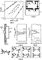
FIG 2 is a schematically depiction of stacked transistors in a sequential 3D integration, comprising a first (lower) tier (21) and a second (top) tier (22). -
FIG 3 is a schematic diagram of the band levels of a Si/SiO2/HfO2/TiN stack. -
FIG 4 is a graph of the probability density functions of the hole trap levels in the SiO2 IL-as estimated by modelling the NBTI transients recorded on the as-deposited gate stack with the Non-Radiative Multi-Phonon theory-, as deposited with a 5 nm TiN layer (solid), after a post-metal anneal at 525 °C for 2 h (dash), and after a typical 'reliability anneal' (∼900 °C in He) (long dash-short dash). -
FIG 5 is a graph showing-for comparison withFIG 4 -ab-initio statistical calculations of hydroxyl-E' (long dash-short dash), hydrogen bridge (solid) and oxygen vacancy (dash) charge transition levels. The hole trap levels in the SiO2 IL (FIG 4 ) compare well with the levels calculated for hydroxyl-E' and hydrogen bridge, but not with the deep levels calculated for the oxygen vacancies. -
FIG 6 is a schematically depiction of a regular defect-free tetrahedral SiO2 configuration (left), and neutral (top row) and positive stable (bottom row) configurations of hydroxyl-E' (dash-dot), hydrogen bridge (solid) and oxygen vacancy (dash) microscopic defect structures. -
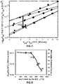
FIG 7 is a graph showing the effective NBTI-induced trapped charge sheet density ΔNeff measured for increasing stress Eox (tstress = 1 ks, T = 25 °C to expose mainly the trapping component) on RMG HKMG stacks with different IL's: a chemical oxide (∼0.7 nm) (circle), three thermal oxides (∼1.2 nm) grown at 600 (square), 700 (diamond) and 900 (star) °C, an equivalent 700 °C thermal oxide that was further exposed after HKMG to a post-metal 850 °C 'reliability anneal' (triangle). -
FIG 8 is a graph of the trapped charge density (ΔNeff at Eox = 4.3 MV/cm, cf.FIG 7 ) plotted as a function of the highest temperature seen by the IL during fabrication. The notable drop above 600 °C compares well with the drop in Si-O bond stretching (line) reported by San Andrés et al. (cf. infra). -
FIG 9 is a sketched graph of the probability density function (PDF) of Si-O bonds in function of their length for SiO2 formed at low (solid) and high (dashed) temperature. Si-O bonds stretched beyond ∼1.65 Å can form hydroxyl-E' defects and the fraction of stretched Si-O bonds is larger in a low temperature oxide, e.g. due to unrelaxed interface strain. -
FIG 10 is a sketched graph of the hole trap density Nt before (solid) and after (dashed) increased oxidation temperature, or H* treatment in accordance with the present invention. The tail end of the hole trap defect band extends above the Si valence band edge (Ev ), resulting in a (large) positive oxide charge density, but can be suppressed at low temperatures by a hydrogen treatment in accordance with the present invention. -
FIG 11 is a diagram of the effect of hydrogen removal on hydroxyl-E' (top left) and hydrogen bridge (top right) defects. By removing the sticking hydrogen atom, the hydroxyl-E' would tend to reform a correct (i.e. defect free) Si-O-Si configuration (bottom left), while the hydrogen bridge would transform into an oxygen vacancy (bottom right), with transition level too deep for charging at operating voltages, cf.FIG 4-FIG 6 . As such, both hydroxyl-E' and hydrogen bridge passivation by an incoming additional hydrogen atom, or removal of the sticking hydrogen by dimerization with an incoming additional hydrogen atom are expected to render the defect site electrically inactive at the operating voltage range. -
FIG 12 is a schematically illustration of a remote plasma setup (e.g. developed on a 300 mm commercial etch tool) to expose the IL to hydrogen radicals at a desired (low) temperature. Depicted are achamber 30 with agas inlet 31, apump 32, plasma coils 33 and transformer coupled plasma (TCP)window 34 for forming a (remote)plasma 35. Through agrid 36, a radical flow 37-such as atomic hydrogen-of theplasma 35 is used to expose a (heated)substrate 38 on asample holder 39. -
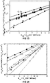
FIG 13 is a graph showing the effective NBTI-induced trapped charge sheet density ΔNeff measured for increasing stress Eox (tstress = 1 ks, T = 25 °C to expose mainly the trapping component) on RMG HKMG stacks with different IL's: two thermal oxides (∼1.2 nm) grown at 600 (square) and 900 (star) °C, and two equivalent 600 °C thermal oxides that was further exposed before HKMG to a high pressure (20 atm) anneal at 450 °C in molecular H2 for 0.5 (diamond) and 2 (circle) h. Exposing the 600 °C IL to high-pressure molecular H2 results only in a 2-3x reduction of the NBTI-induced ΔNeff , i.e. not enough to match the reliability of the reference stack based on a 900 °C IL. -
FIG 14 is a graph showing the effective NBTI-induced trapped charge sheet density ΔNeff measured for increasing stress Eox (tstress = 1 ks, T = 25 °C to expose mainly the trapping component) on RMG HKMG stacks with different IL's: two thermal oxides (∼1.2 nm) grown at 600 (circle) and 900 (star) °C, and four equivalent 600 °C thermal oxides that were further exposed before HKMG to H* respectively at 100 °C for 10" (triangle pointing up), at 300 °C for 10" (square), at 100 °C for 10' (triangle pointing left) and at 300 °C for 10' (diamond). Exposure to H* results in a dramatic reduction (up to ∼20× for 100 °C and ∼100× for 300 °C) of the NBTI-induced ΔNeff (T = 25 °C). The reference stack based on a 900 °C IL can be matched or surpassed with a 10' exposure. -
FIG 15 is a graph showing ΔNeff reduction factors for H* exposures at 100 (hollow circle) and 300 (full circle) °C, modelled (lines) as a first-order reaction using
-
FIG 16 is a box plot showing the EOT of the final stack for different H* exposures on the IL, with reference numbers as forFIG 23 . A marginal EOT increase (1-1.5 Å) is observed for the 10' exposures, but can be suppressed using a subsequent H2 anneal. -
FIG 17 is a box plot showing the eWF of the final stack for different H* exposures on the IL, with reference numbers as forFIG 23 . A gradual increase of the eWF is consistently observed. -
FIG 18 is a graph showing the gate leakage density Jg (sensed at Vfb -0.6 V) of the stacks with different IL's: three thermal oxides grown at 600 (circle), 700 (triangle) and 900 (diamond) °C as references, an equivalent 700 °C thermal oxide that was further exposed to a post-metal 850 °C reliability anneal (six-pointed star), and four equivalent 600 °C thermal oxides exposed to different H* regimens-namely at 100 °C for 10" (plus), at 100 °C for 10' (asterisk) at 300 °C for 10" (square), and at 300 °C for 10' (five-pointed star)-, plotted vs. the EOT of the final stack. Dashed lines depict a typical Jg -EOT scaling trend (10x increase for 0.2 nm scaling). H* exposure always resulted in reduced Jg compared to the 600 °C reference. -
FIG 19 is a plot showing the median Vg -to-breakdown measured in a set of 100 µm2 capacitors with various gate stacks with different IL's: three thermal oxides grown at 600 (circle), 700 (triangle) and 900 (square) °C as references, an equivalent 700 °C thermal oxide that was further exposed to a post-metal 850 °C reliability anneal (diamond), and three equivalent 600 °C thermal oxides exposed respectively to H* at 100 °C for 10" (six-pointed star), to H* at 300 °C for 10" (five-pointed star), and to 20 atm H2 at 450 °C for 2 h (plus), plotted vs. EOT. Exposing the 600 °C IL to H2 or H* results in improved breakdown robustness. -
FIG 20 is a graph showing NBTI-induced ΔNeff vs. stress Eox for gate stacks with different IL's: two thermal oxides (∼1.2 nm) grown at 600 (square) and 900 (star) °C, and three equivalent 600 °C thermal oxides that were further exposed before HKMG respectively to H* at 100 °C for 10' (circle), to H* at 100 °C for 10' and subsequently to 1 atm O2 at 450 °C for 0.5 h (diamond), and to H* at 200 °C for 10" and subsequently to 1 atm O2 at 450 °C for 0.5 h (diamond). The exposure to 1 atm O2 induced re-oxidation of the Si surface at low temperature, which negates the NBTI improvement. -
FIG 21 is a graph showing NBTI-induced ΔNeff vs. stress Eox for gate stacks with different IL's: two thermal oxides (∼1.2 nm) grown at 600 (square) and 900 (star) °C, and two equivalent 600 °C thermal oxides that were further exposed before HKMG respectively to 20 atm O2 at 450 °C for 0.5 h (diamond), and to 20 atm O2 at 450 °C for 0.5 h and subsequently to H* at 300 °C for 10" (circle). The exposure to 20 atm O2 induced an EOT regrowth of ∼2 Å, resulting in further degraded NBTI; a subsequent exposure to H* (at 300 °C for 10") improves the reliability, which might be completely restored by longer exposures (e.g. 10'; dashed line). -
FIG 22 is a graph showing NBTI-induced ΔNeff vs. stress Eox for gate stacks with different IL's: two thermal oxides (∼1.2 nm) grown at 600 (square) and 900 (star) °C, and an equivalent 900 °C thermal oxide that was further exposed before HKMG to H* at 300 °C for 10" (diamond). Exposing a 900 °C IL to H* (at 300 °C for 10") results in further reliability improvement. -
FIG 23 is a correlation plot of NBTI reliability (shown as the Vov necessary to reach a 2.5 mV shift after 1 ks stress at 25 °C) vs. the eWF for gate stacks with different IL's as previously described: a 600 °C thermal oxide (1), 600 °C thermal oxide further exposed to H* at 100 °C for 10" (2), 600 °C thermal oxide further exposed to H* at 300 °C for 10" (3), 600 °C thermal oxide further exposed to H* at 100 °C for 10' (4), 600 °C thermal oxide further exposed to H* at 300 °C for 10' (5), 600 °C thermal oxide further exposed to H* at 300 °C for 10" without (post-metal) sintering anneal in the presence of H2 (6), 600 °C thermal oxide further exposed to H* at 100 °C for 10" and subsequently to 1 atm O2 at 450 °C for 0.5 h (7), 600 °C thermal oxide further exposed to H* at 200 °C for 10" and subsequently to 1 atm O2 at 450 °C for 0.5 h (8), 600 °C thermal oxide further exposed to 20 atm H2 at 450 °C for 0.5 h (9), 600 °C thermal oxide further exposed to 20 atm H2 at 450 °C for 2 h (10), 600 °C thermal oxide further exposed to 20 atm O2 at 450 °C for 0.5 h (11), 600 °C thermal oxide further exposed to 20 atm O2 at 450 °C for 2 h (12), 600 °C thermal oxide further exposed to 20 atm O2 at 450 °C for 0.5 h and subsequently to H* at 300 °C for 10" (13), 700 °C thermal oxide (14), 700 °C thermal oxide further exposed to a reliability anneal at 850 °C (15), 900 °C thermal oxide (16), and 900 °C thermal oxide further exposed to H* at 300 °C for 10" (17). Stacks with improved reliability-i.e. with IL grown at higher temperature, or exposed to H2 or H*-always show an increased eWF (i.e. reduced positive charge, cf.FIG 10 ). Note that the Vov improvement range (0.241→1.8V) is much larger than the eWF increase (4.73 eV → 5.04 eV), which proves that the NBTI improvement is not solely due to fixed charge reduction (lower Eox at same Vov ). -
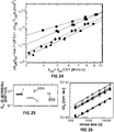
FIG 24 is a graph showing NBTI-induced ΔNeff vs. stress Eox for gate stacks with different IL's: two thermal oxides (∼1.2 nm) grown at 600 (square) and 900 (star) °C, and two equivalent 600 °C thermal oxides that were further exposed before HKMG respectively to H* at 300 °C for 10" (diamond), and to H* at 300 °C for 10" but without post-metal sintering anneal in the presence of H2. Omitting the final post-metal sintering (at 400 °C for 20' in 1 atm H2) partially negates the improvement induced by IL exposure to H* (at 300 °C for 10"), and results in larger time-zero Dit (inset, 2×10¹¹ vs. 4×10¹⁰ /cm2/eV). - is a box plot showing the time-zero Dit (i.e. D it0) the final stack for different types of IL, with reference numbers as for
FIG 23 . Omitting the final post-metal sintering (cf. supra) results in larger D it0 (2×10¹¹ vs. 4×10¹⁰ /cm2/eV). -
FIG 26 is a graph showing NBTI-induced Dit generation kinetics monitored by the parallel conductance peak in depletion (f = 10 kHz) during 125 °C stress at Eox = 5.7 MV/cm for gate stacks with different IL's: three thermal oxides (∼1.2 nm) grown at 600 (hollow circle), 700 (hollow diamond) and 900 (solid circle) °C, an equivalent 700 °C thermal oxide that was further exposed after HKMG to a post-metal 850 °C 'reliability anneal' (solid diamond), an equivalent 600 °C thermal oxide that was further exposed before HKMG to a high pressure (20 atm) anneal at 450 °C in molecular H2 for 2 h (cross) and an equivalent 600 °C thermal oxide that was further exposed before HKMG to H* for 10" at 300 °C (triangle). The same kinetics-with a slope of ∼0.28-is observed irrespective of the IL treatment; exposure to H2 or H* reduces the ΔDit on the 600 °C IL stack, matching a 700 °C reference IL, while a more stable interface is observed in the 850-900 °C IL's. -
FIG 27 is a graph showing NBTI-induced ΔDit generation monitored on various gate stacks with reference numbers as forFIG 23 , by the parallel conductance peak in depletion (f = 25 kHz) during stress at 125 °C and increasing Eox. -
FIG 28 is a bar chart showing estimated Eox to induce ΔDit = 3×1011 cm-2eV-1 after 1 ks stress (cutline ofFIG 27 ) plotted vs. the stack configuration, from worst to best. Re-oxidation at 450 °C results in poorest interface stability, which is instead substantially improved by increasing the oxidation T or exposing the (600 °C) IL to H* or HP (high pressure) H2. -
FIG 29 is a graph of the ΔDit (E) profile induced by 20 ks NBTI stress at Eox = 5.7 MV/cm and 125 °C, as extracted from C-V stretch-out correction for gate stacks with different IL's: three thermal oxides (∼1.2 nm) grown at 600 (long dash), 700 (dotted) and 900 (solid) °C, an equivalent 700 °C thermal oxide that was further exposed after HKMG to a post-metal 850 °C 'reliability anneal' (short dash), an equivalent 600 °C thermal oxide that was further exposed before HKMG to a high pressure (20 atm) anneal at 450 °C in molecular H2 for 2 h (dash-dot) and an equivalent 600 °C thermal oxide that was further exposed before HKMG to H* for 10" at 300 °C (dash-dot-dot). -
FIG 30 is a graph of the ΔDit (E) profile as inFIG 29 , normalized to the peak amplitudes. -
FIG 31 is a graph showing NBTI-induced ΔNeff vs. stress Eox after 1 ks stress, here at elevated stress temperature (125 °C) for gate stacks with different IL's: three thermal oxides (∼1.2 nm) grown at 600 (square), 700 (hollow triangle) and 900 (hollow star) °C, an equivalent 700 °C thermal oxide that was further exposed after HKMG to a post-metal 850 °C 'reliability anneal' (solid star), an equivalent 600 °C thermal oxide that was further exposed before HKMG to a high pressure (20 atm) anneal at 450 °C in molecular H2 for 2 h (plus) and three equivalent 600 °C thermal oxide that were further exposed before HKMG to H* for respectively 10' at 100 °C (diamond), 10" at 300 °C (solid triangle) and 10' at 300 °C (circle). Exposing a 600 °C IL to H* (10', 100/300 °C) supresses hole trapping (cf.FIG 14 ), and also moderately reduces the Dit generation (cf.FIG 26-FIG 30 ), yielding best overall NBTI reliability, even with respect to a 900 °C IL or to a stack exposed to a 850 °C 'reliability anneal'. -
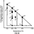
FIG 32 is a graph of surface positive charge (Deal) and NBTI hole traps in function of temperature with reference numbers as forFIG 23 ; the different symbols reflect different (final) treatment/exposure temperatures: none (star), 100 °C (circle), 300 °C (triangle), 450 °C (diamond) or 850 °C (square). The present invention extends the validity of the "Deal-triangle" from surface positive charge to NBTI reliability. Hole trapping in SiO2 is controlled by oxidation temperature, with the last oxidation determining the charging trap density. After oxidation, hole traps can be passivated by H* at low temperature (100-300 °C) or-less effectively and at higher temperatures (450 °C)-by high pressure H2. - In the different figures, the same reference signs refer to the same or analogous elements.
- The present invention will be described with respect to particular embodiments and with reference to certain drawings but the invention is not limited thereto but only by the claims. The drawings described are only schematic and are non-limiting. In the drawings, the size of some of the elements may be exaggerated and not drawn on scale for illustrative purposes. The dimensions and the relative dimensions do not correspond to actual reductions to practice of the invention.
- Furthermore, the terms first, second, third and the like in the description and in the claims, are used for distinguishing between similar elements and not necessarily for describing a sequence, either temporally, spatially, in ranking or in any other manner. It is to be understood that the terms so used are interchangeable under appropriate circumstances and that the embodiments of the invention described herein are capable of operation in other sequences than described or illustrated herein.
- Moreover, the terms top, bottom, over, under and the like in the description and the claims are used for descriptive purposes and not necessarily for describing relative positions. It is to be understood that the terms so used are interchangeable with their antonyms under appropriate circumstances and that the embodiments of the invention described herein are capable of operation in other orientations than described or illustrated herein.
- It is to be noticed that the term "comprising", used in the claims, should not be interpreted as being restricted to the means listed thereafter; it does not exclude other elements or steps. It is thus to be interpreted as specifying the presence of the stated features, integers, steps or components as referred to, but does not preclude the presence or addition of one or more other features, integers, steps or components, or groups thereof. The term "comprising" therefore covers the situation where only the stated features are present and the situation where these features and one or more other features are present. Thus, the scope of the expression "a device comprising means A and B" should not be interpreted as being limited to devices consisting only of components A and B. It means that with respect to the present invention, the only relevant components of the device are A and B.
- Reference throughout this specification to "one embodiment" or "an embodiment" means that a particular feature, structure or characteristic described in connection with the embodiment is included in at least one embodiment of the present invention. Thus, appearances of the phrases "in one embodiment" or "in an embodiment" in various places throughout this specification are not necessarily all referring to the same embodiment, but may. Furthermore, the particular features, structures or characteristics may be combined in any suitable manner, as would be apparent to one of ordinary skill in the art from this disclosure, in one or more embodiments.
- Similarly, it should be appreciated that in the description of exemplary embodiments of the invention, various features of the invention are sometimes grouped together in a single embodiment, figure, or description thereof for the purpose of streamlining the disclosure and aiding in the understanding of one or more of the various inventive aspects. This method of disclosure, however, is not to be interpreted as reflecting an intention that the claimed invention requires more features than are expressly recited in each claim. Rather, as the following claims reflect, inventive aspects lie in less than all features of a single foregoing disclosed embodiment. Thus, the claims following the detailed description are hereby expressly incorporated into this detailed description, with each claim standing on its own as a separate embodiment of this invention.
- Furthermore, while some embodiments described herein include some but not other features included in other embodiments, combinations of features of different embodiments are meant to be within the scope of the invention, and form different embodiments, as would be understood by those in the art. For example, in the following claims, any of the claimed embodiments can be used in any combination.
- In the description provided herein, numerous specific details are set forth. However, it is understood that embodiments of the invention may be practised without these specific details. In other instances, well-known methods, structures and techniques have not been shown in detail in order not to obscure an understanding of this description.
- The following terms are provided solely to aid in the understanding of the invention.
- As used herein, and unless otherwise specified, atomic hydrogen (H*) refers to the neutral radical of the chemical element hydrogen. Atomic hydrogen is also known under its IUPAC (International Union of Pure and Applied Chemistry) systematic name of 'monohydrogen'.
- As used herein, and unless otherwise specified, bias temperatures instability (BTI) is a type of metal-oxide-semiconductor structure (e.g. transistor or capacitor) aging that has a negative effect on the performance characteristics of the MOS structure. The degradation may for example typically manifest as an increasing threshold voltage over time. Depending on the (gate) bias voltage under which the BTI manifests, one can distinguish negative (NBTI) or positive (PBTI) BTI. NBTI is typically of most concern for pMOS, while PBTI is typically of most concern for nMOS; however,-more generally-this can differ depending on the operating mode (e.g. bias regime) of the semiconductor structure. (N)BTI can for instance be studied by stress/recovery sequences during which the effective trapped charge sheet density ΔNeff can be determined from the threshold voltage (transistor) or flatband voltage (capacitor) shift measured for increasing stress Eox (cf. Example).
- In a first aspect, the present invention relates to a method for improving a bias temperature instability of a SiO2 layer, comprising: (a) exposing the SiO2 layer to atomic hydrogen.
- In preferred embodiments, the bias temperature instability may be a negative bias temperature instability. Although the present invention can in general improve both the NBTI and PBTI of the SiO2 layer,-compared to NBTI, which is typically dominated by hole traps-PBTI is typically sensitive to electron traps in a different energy range of the dielectric (more particularly, above the Si conduction band). SiO2 tends to inherently have a relatively low trap density at those energies, so that any improvement brought to PBTI through the present atomic hydrogen treatment is comparatively typically lower than for NBTI.
- In embodiments, step a may be performed at a temperature between 60 and 750 °C, preferably between 75 and 600 °C, more preferably between 85 and 450 °C, yet more preferably between 100 and 300 °C. In embodiments, step a may be performed for a duration of between 1 s and 120 min, preferably between 2 s and 60 min, more preferably between 5 s and 30 min, yet more preferably between 7 s and 15 min, most preferably between 10 s and 10 min.
- In embodiments, step a may comprise exposing the SiO2 layer to atomic hydrogen from a remote plasma. A remote plasma is advantageous in that it allows to expose the SiO2 layer-through the plasma afterglow-to atomic hydrogen, without directly subjecting the SiO2 to the plasma as such. By contrast, a direct plasma may cause bombardment on and therefor deterioration of the SiO2 layer. Moreover, in a remote plasma setup, the temperature of the substrate (e.g. wafer) during the exposure treatment can be controlled independently.
- In embodiments, the method may comprise a further step a'-before step a-of: (a') growing the SiO2 layer at a temperature of 750 °C or lower, preferably 700 °C or lower, more preferably 650 °C or lower, yet more preferably 600 °C or lower. In embodiments, the SiO2 layer may be grown using a thermal or chemical oxidation.
- In embodiments, the SiO2 layer may not have been exposed to a temperature of more than 900 °C, preferably not more than 800 °C, more preferably not more than 700 °C, yet more preferably not more than 600 °C, most preferably not more than 300 °C. For example, the SiO2 layer may be grown using a thermal oxidation at 600 °C or lower, or by chemical oxidation at 300 °C or lower. In embodiments, the SiO2 layer may not have been exposed to such temperatures before step a. For example, the SiO2 layer may have been formed at a relatively low temperature (e.g. ∼600 °C) and may not have been exposed to a so-called 'reliability anneal' (typically performed at temperatures of about 850-900 °C). Such layers which have not 'seen' such a relatively high temperature typically comprise more defects that contribute to a higher bias temperature instability, so that an atomic hydrogen treatment may in those case have comparatively more effect. In embodiments, the SiO2 layer may not have been exposed to such temperatures before, during and after step a. Not exposing the SiO2 layer at any point to a high temperature is advantageously very attractive for applications in which the available thermal budget is a concern (e.g. as in sequential 3D integration).
- In embodiments, the method may comprise a further step b-after step a-of: (b) sintering the SiO2 layer in the presence of molecular hydrogen (H2). Without being bound by theory, it has been observed that atomic hydrogen can sometimes induce interface quality degradation by de-passivation of Si-H bonds (e.g. at the interface between the Si crystal surface and the SiO2). This can dampen the positive effect of the atomic hydrogen treatment that is observed on the bias temperature instability. However, a standard 'short sintering anneal'-which is already routinely performed in RMG process flows-can easily remove this dampening and restore the full effect. In embodiments, step b may be performed directly after step a and/or later in the process flow (e.g. at the end of the RMG process flow). For example, the SiO2 layer may be sintered in the presence of H2 immediately after step a and a short sintering anneal in the presence of H2 may be performed at the end of the RMG process flow. In embodiments, the molecular hydrogen may be provided in the form of H2 as such (e.g. H2 gas) or forming gas (a mixture of H2 and N2).
- In embodiments, step b may be performed at a temperature between 200 and 600 °C, preferably between 300 and 500 °C, such as 400 °C. In embodiments, step b may be performed for a duration of between 2 and 120 min, preferably between 5 and 60 min, more preferably between 10 and 30 min, most preferably between 15 and 25 min, such as 20 min.
- In embodiments, the SiO2 layer may have a thickness below 10 nm, preferably below 5 nm, yet more preferably below 3 nm, yet more preferably between 0.5 and 2.5 nm. For example, the SiO2 layer may have a thickness of 0.6 nm, 1.2 nm or 2.2 nm.
- In embodiments, any feature of any embodiment of the first aspect may independently be as correspondingly described for any embodiment of any of the other aspects.
- In a second aspect, the present invention relates to a method for forming a SiO2 layer for a metal-oxide-semiconductor, comprising: (a) depositing a SiO2 layer, and (b) improving a bias temperature instability of a SiO2 layer using the method according to any embodiment of the first aspect.
- In embodiments, the metal-oxide-semiconductor may be a metal-oxide-transistor or a metal-oxide capacitor, preferably a metal oxide transistor. In embodiments, the SiO2 layer may be a SiO2 interlayer for the metal-oxide semiconductor.
- In embodiments, the metal-oxide-semiconductor may be a p-type metal-oxide-semiconductor. NBTI tends to affect pMOS more than nMOS, so that a larger benefit will typically be observed for pMOS (cf. supra).
- In embodiments, the method may be for improving a bias temperature instability of the SiO2 layer during a sequential 3D integration process.
- In embodiments, any feature of any embodiment of the second aspect may independently be as correspondingly described for any embodiment of any of the other aspects.
- In a third aspect, the present invention relates to a use of atomic hydrogen for improving a bias temperature instability of a SiO2 layer.
- In embodiments, the bias temperature instability may be a negative bias temperature instability.
- In embodiments, any feature of any embodiment of the third aspect may independently be as correspondingly described for any embodiment of any of the other aspects.
- In a fourth aspect, the present invention relates to a SiO2 layer obtainable by the method according to any embodiment of the first aspect.
- In embodiments, the effective trapped charge sheet density ΔNeff (see e.g. Example) of such a SiO2 layer-measured after a stress time tstress of 1 ks with a sense delay tdelay of 10 ms at a temperature T of 25 °C for a stress Eox of 5 MV/cm-may be equal to 1×10¹⁰/cm2 or lower, preferably 7×10⁹/cm2 or lower, more preferably 5×10⁹/cm2 or lower, yet more preferably 2×10⁹/cm2 or lower, most preferably 1×10⁹/cm2 or lower.
- In embodiments, any feature of any embodiment of the fourth aspect may independently be as correspondingly described for any embodiment of any of the other aspects.
- The invention will now be described by a detailed description of several embodiments of the invention. It is clear that other embodiments of the invention can be configured according to the knowledge of the person skilled in the art without departing from the true technical teaching of the invention, the invention being limited only by the terms of the appended claims.
- MOS capacitors were fabricated on a 300 mm test vehicle in an RMG flow. Different thermal SiO2 IL's with thickness of about 1.2 nm and grown at 600, 700 or 900 °C by ISSG (in situ steam generation) or RTO (rapid thermal oxidation) processes were considered. Additionally, similar experiments were performed on an ultrathin ∼0.5 nm chemical oxide IL obtained by a wet cleaning on the Si surface was also considered; the results thereof are not discussed in detail herein, but suffice it to say that similar trends were observed for such ultrathin IL's as for the thermal oxides which are extensively discussed below. Treatments were performed on the IL right after formation. The gate stack was completed in all cases by depositing ∼1.8 nm HfO2 and 5 nm TiN by ALD (atomic layer deposition), and 60 nm W by ALD. Unless noted otherwise, a final sintering (at 400 °C for 20' in molecular H2) was performed to passivate the Si/SiO2 interface. For reference, one stack comprised a chemical oxide IL (∼0.7 nm) and another stack (with a 700 °C IL) was exposed to a 'reliability anneal' (at 850 °C for 1.5" in He, after deposition of a sacrificial TiN/α-Si gate). In selected cases, after formation the IL was exposed to atomic hydrogen generated in a remote plasma, or to H2 (20 atm) and/or to O2 (1 or 20 atm), as discussed in the next section. EOT (equivalent oxide thickness) and eWF (effective work function) were estimated from C-V curves measured on capacitor test structures with the CVC Hauser tool. NBTI was studied by stress/recovery sequences (minimum sense delay ∼10 ms; stress times up to 1 ks) at increasing stress Eox ≈ (Vg - V fb0)/(EOT + 0.4 nm)-with Eox the gate oxide electric field, Vg the gate bias voltage and V fb0 the flat-band voltage at time-zero (i.e., without degradation)-at 25 °C (to sense mainly the hole trapping component) and at 125 °C (to sense also the interface defects Dit generation component, which becomes more visible at elevated temperature within a limited stress measurement time). Degradation was benchmarked as the induced change in effective charge sheet density ΔNeff ≡ ΔVfb.Cox /q-with Neff the effective charge sheet density, ΔVfb the NBTI-induced flat-band voltage shift, Cox the oxide capacitance and q the elementary charge. An additional set of NBTI stresses up to 20 ks was performed at 125 °C, periodically interrupted to measure the C-f-V response to directly monitor Dit generation from C-V stretch out correction or from the parallel conductance peak in depletion.
- The so-called 'reliability anneal'-performed at about 850-900 °C-is a crucial step in RMG HKMG gate stack fabrication, but it is not compatible with stacked top tier fabrication. Omitting this post-metal anneal results in poor PBTI and NBTI reliability with induced threshold voltage (Vth ) shifts ∼10× larger compared to the Foundry 28 nm process from Franco et al. (2018) (
FIG 1 ). The imec/T.U. Wien BTI modelling framework Comphy (RZEPA, Gerhard, et al. Comphy-A compact-physics framework for unified modelling of BTI. Microelectronics Reliability, 2018, 85: 49-65.) was used to estimate the hole trap energy levels within the SiO2 bandgap, and to compare with ab initio calculations of the charge transition levels of known SiO2 defect structures (FIG 4-FIG 6 ). The often-invoked oxygen vacancies show too deep charge transition levels to be of relevance for the NBTI reliability of low voltage Logic technologies. In contrast, the hydroxyl-E' (i.e. a hydroxyl-group replacing an oxygen) and hydrogen bridge (i.e. a hydrogen replacing an oxygen) structures (FIG 5-FIG 6 ) are expected to have charge transition levels in the vicinity of Si valence band edge (Ev ) and are therefore compatible with the observed experimental NBTI signature. In particular, the hydroxyl-E' tends to form in the presence of stretched Si-O bonds. To investigate the role of oxidation temperature on the hole trap formation, the NBTI reliability of stacks was compared with various IL's (FIG 7 ): a strong dependence is observed, with the IL grown at the highest temperature (900 °C) showing the best reliability. Note that performing an 850 °C post-metal 'reliability anneal' yields a trap density as low as the one measured on a 900 °C IL, suggesting a key role of the last oxidation temperature. The dependence of the hole trap density on the oxidation temperature matches well the stretched Si-O FTIR (Fourier-transform infrared spectroscopy) signal reported by San Andrés et al. (SAN ANDRÉS, E., et al. Rapid thermal annealing effects on the structural properties and density of defects in .) (FIG 8 ). These initial observations suggest the qualitative model depicted inFIG 9-FIG 10 : a reduced oxidation temperature does not allow for a complete relaxation of strain at the Si/SiO2 interface, resulting in a larger presence of stretched Si-O bonds, which are precursors for hydroxyl-E' formation. As a consequence, the hole trap and fixed positive charge densities depend on the oxidation temperature (FIG 10 ), where the hole trap band tail reaching above Si Ev is perceived as additional fixed charge, as it would be positively charged already at flat-band. While formation of these defects is an unavoidable consequence of thermodynamics, we demonstrate that this specific type of hole traps can be passivated after IL formation at low temperature by proper hydrogen treatments. - The hydroxyl-E' was suggested as an NBTI-inducing defect already in 1995, and has been recently extensively studied in the context of RTN (random telegraph noise)/NBTI kinetics models by Grasser et al. (GRASSER, Tibor, et al. On the volatility of oxide defects: Activation, deactivation, and transformation. In: 2015 IEEE International Reliability Physics Symposium. IEEE, 2015. p. 5A. 3.1-5A. 3.8.).
Fig. 14 therein shows a diagram of four hydroxyl-E' configurations to model NBTI kinetics: the Si dangling bond (1 and 1' configurations) loses its electron upon hole capture, yielding the positive meta-stable (2') and stable (2) configurations. By various interactions with hydrogen the defect can transform into a precursor state (left). - The possibility of preferentially inducing defect 'volatility' during the fabrication process was therefore envisioned, by directly exposing the IL to hydrogen. Density-functional theory calculations suggest that exposure to atomic hydrogen can yield spontaneous passivation of the Si-dangling bond at the hydroxyl-E' and hydrogen bridges sites through the reactions:


- Alternatively, removal of the sticking hydrogen (over a thermal barrier) by dimerization and H2 molecule release, could also de-activate the defects: the hydroxyl-E' would tend to reform a correct Si-O-Si bond, while the hydrogen bridge (
FIG 11 ) would transform into an oxygen vacancy not contributing to NBTI (cf.FIG 4-FIG 5 ). Note that: (i) hydrogen species might also activate defects at precursor sites, and therefore properly controlling the exposure conditions to favourably skew the reaction balance can be beneficial, (ii) similar passivating reactions could be induced also by exposure to molecular hydrogen, though over sizeable energy barriers. Consistently, we could only achieve marginal 2-3x NBTI improvement when exposing a 600 °C IL to molecular hydrogen for up to 2 h at 450 °C, despite resorting to 20 atm pressure to maximize H2 availability (FIG 13 ). - We therefore designed a remote hydrogen plasma process (
FIG 12 ) to expose the IL to hydrogen radicals (H*). As suggested by theory, this results in a very effective passivation of the hole traps (FIG 14 ): a dramatic NBTI improvement is observed (∼2-20× for 10"-10' exposures at 100 °C, and ∼7-100× at 300 °C) due to the suppression of the hole trap density down to or below the level of a 900 °C reference IL. By comparing the trap density reduction factors observed for the different exposures, an effective thermal barrier of 0.21 ± 0.06 eV is estimated for the beneficial reaction(s) taking place at the defect sites (FIG 15 ). We note that the short H* exposures do not result in any EOT increase, while a marginal increase of 1-1.5 Å was observed for the 10' exposures at 100-300 °C; however, it was found that this can be controlled/suppressed by for instance using subsequently (e.g. directly after the H* exposure) an additional H2 anneal (e.g. at ∼400 °C)-cf. infra. In contrast, a gradual increase of the eWF is consistently observed for all the H* exposures (FIG 16-FIG 17 ), suggesting concurrent suppression of both hole traps and positive oxide charge (cf.FIG 10 ). Moreover, the H* exposures results in reduced gate leakage (FIG 18 ) and improved breakdown robustness (FIG 19 ). - Performing an additional anneal in oxygen (450 °C for 0.5 h under 1 atm O2) after exposing the 600 °C IL to H* results again in very poor NBTI reliability (
FIG 20 ). This suggests that additional oxidation of the Si surface (now at 450 °C, instead of the original 600 °C oxidation) increases again the near-interface defect density. To prove the reversibility of the defect formation/passivation with H* processes, we first expose the 600 °C IL to a high-pressure oxygen anneal (450 °C for 0.5 h under 20 atm O2) which induces ∼2 Å oxide regrowth: this procedure yields the worst NBTI reliability, which is nevertheless improved again by subsequent H* exposure (FIG 21 ). Conversely, even a high-quality 900 °C IL is further improved by H* (FIG 22 ), suggesting this treatment can be beneficial (although not strictly necessary) also in a standard high thermal budget fabrication flow. - Across all the IL growth/treatment combinations studied, a remarkable correlation between the NBTI reliability and the eWF is consistently observed (
FIG 23 ), as postulated by our initial qualitative model (cf.FIG 9-FIG 10 ): the IL's grown at the lowest T (450 °C) show the lowest maximum-allowed gate overdrive voltage Vov for sufficient NBTI reliability (∼0.2 V) and also the lowest eWF (∼4.73 eV despite the use of a high WF TiN gate); increasing the oxidation temperature or exposing the stack to a 'reliability anneal' enhances both the max Vov and the eWF; similarly, both the H2 and H* treatments (the latter most effectively) enhance the max Vov up to 1.8 V and eWF up to 5.04 eV along the same trend. - A possible detrimental effect of H* exposure is the de-passivation of Si-H bonds at the Si/SiO2 interface. However, this is readily solved by performing a standard sintering anneal (e.g. at 400 °C for 20' in H2) (directly) after the H* exposure and/or at the end of the RMG flow. Without being bound by theory, it is believed that such a sintering anneal immediately re-passivates dangling bonds (Pb's) at the Si surface, resulting also in an improved EOT stability (cf. supra). Omitting the latter after H* exposure of the IL (
FIG 24 ) results indeed in poor interface passivation (time-zero interface defects, i.e. without NBTI-induced degradation, D it0 ∼ 2 × 10¹¹ /cm2/eV), and in a less improved NBTI reliability. To investigate interface stability, additional NBTI stresses were performed at elevated temperature (125 °C), and Dit generation was monitored by the parallel conductance in depletion.FIG 26 reports the Dit generation kinetics measured at accelerated stress conditions (Eox = 5.7 MV/cm) in selected stacks. In all cases, similar time-dependences are observed: H*, high pressure H2 or exposure of the 600 °C IL results in improved interface stability, comparable to a 700 °C IL, although not as good as 900 °C or 850 °C-exposed IL's. The field-acceleration of the Dit generation for various gate stack configurations is reported inFIG 27-FIG 28 : a beneficially stronger field-acceleration is observed with H* exposure, resulting in smaller degradation at operating Eox. Moreover, the energy profile of the NBTI-generated Dit appears similar in all stacks (FIG 29-FIG 30 ), ruling out the formation of different types of interface states as a potential consequence of H* exposure. - To understand the NBTI reliability improvement demonstrated with H* exposure further, Comphy models were calibrated for all the studied gate stacks. Dit generation was first calibrated based on the conductance peak increase with stress; a hole trap defect band was then included and calibrated to accurately reproduce the measured NBTI stress/recovery traces. The models were used here to visualize the reduction in hole trap density induced by increasing the oxidation temperature, or by treating the IL with hydrogen: H* exposure was observed to yield the lowest density of hole traps in the vicinity of Si Ev (i.e. it resulted in the least detrimental defect band), and as a consequence to yield the best overall NBTI reliability, even when compared with conventional high-temperature (e.g. 900 °C) IL's at elevated stress temperature (
FIG 31 ). - Excessive hole trapping limits the NBTI reliability of low temperature SiO2 IL's. The NBTI dependence on the (last) IL oxidation temperature was correlated to unrelaxed interface strain, which induces excessive formation of hydrogen-related hole traps (hydroxyl-E'). By combining experimental observations with theoretical insights, a low temperature (100-300 °C) atomic hydrogen treatment was developed which dramatically reduces the density of hole traps, yielding an oxide quality superior to a 900 °C reference IL. A correlation between NBTI reliability and positive oxide charges was established, ascribing the latter also to the tail of the SiO2 hole trap defect band reaching above Si Ev . These insights extend the validity of the 'Deal triangle' of oxidation (DEAL, Bruce E., et al. Characteristics of the surface-state charge (Qss) of thermally oxidized silicon. Journal of the Electrochemical Society, 1967, 114.3: 266.) also to NBTI reliability (
FIG 32 ), and enable the fabrication of high quality SiO2 at low temperatures by controlling the hydrogen dynamics, which represents a breakthrough for stacked CMOS tier fabrication. - It is to be understood that although preferred embodiments, specific constructions, configurations and materials have been discussed herein in order to illustrate the present invention. It will be apparent to those skilled in the art that various changes or modifications in form and detail may be made without departing from the scope of the invention as defined in the appended claims.
Claims (15)
- A method for improving a bias temperature instability of a SiO2 layer, comprising:a. exposing the SiO2 layer to atomic hydrogen.
- The method according to claim 1, wherein step a is performed at a temperature between 60 and 750 °C, preferably between 75 and 600 °C, more preferably between 85 and 450 °C, yet more preferably between 100 and 300 °C.
- The method according to any of the previous claims, wherein step a is performed for a duration of between 1 s and 120 min, preferably between 2 s and 60 min, more preferably between 5 s and 30 min, yet more preferably between 7 s and 15 min, most preferably between 10 s and 10 min.
- The method according to any of the previous claims, wherein step a comprises exposing the SiO2 layer to atomic hydrogen from a remote plasma.
- The method according to any of the previous claims, comprising a further step a'-before step a-of:
a'. growing the SiO2 layer at a temperature of 750 °C or lower, preferably 700 °C or lower, more preferably 650 °C or lower, yet more preferably 600 °C or lower. - The method according to any of the previous claims, wherein the SiO2 layer has not been exposed to a temperature of more than 900 °C, preferably not more than 800 °C, more preferably not more than 700 °C, yet more preferably not more than 600 °C, most preferably not more than 300 °C.
- The method according to any of the previous claims, comprising a further step b-after step a-of:
b. sintering the SiO2 layer in the presence of molecular hydrogen. - The method according to claim 6, wherein step b is performed at a temperature between 200 and 600 °C, preferably between 300 and 500 °C.
- The method according to any of claims 6 to 8, wherein step b is performed for a duration of between 2 and 120 min, preferably between 5 and 60 min, more preferably between 10 and 30 min, most preferably between 15 and 25 min.
- The method according to any of the previous claims, wherein the SiO2 layer has a thickness below 10 nm, preferably below 5 nm, yet more preferably below 3 nm, yet more preferably between 0.5 and 2.5 nm.
- A method for forming a SiO2 layer for a metal-oxide-semiconductor, comprising:a. depositing a SiO2 layer, andb. improving a bias temperature instability of the SiO2 layer using the method according to any of the previous claims.
- The method according to claim 11, wherein the metal-oxide-semiconductor is a p-type metal-oxide-semiconductor.
- Use of atomic hydrogen for improving a bias temperature instability of a SiO2 layer.
- The use according to claim 13, wherein the bias temperature instability is a negative bias temperature instability.
- A SiO2 layer obtainable by the method according to any of claims 1 to 10.
Priority Applications (3)
| Application Number | Priority Date | Filing Date | Title |
|---|---|---|---|
| EP20212064.8A EP4009351B1 (en) | 2020-12-04 | 2020-12-04 | Improving bias temperature instability of sio2 layers |
| US17/369,709 US12009204B2 (en) | 2020-12-04 | 2021-07-07 | Bias temperature instability of SiO2 layers |
| CN202110780088.3A CN114597116A (en) | 2020-12-04 | 2021-07-09 | Improvement of Bias Temperature Instability of SiO2 Layer |
Applications Claiming Priority (1)
| Application Number | Priority Date | Filing Date | Title |
|---|---|---|---|
| EP20212064.8A EP4009351B1 (en) | 2020-12-04 | 2020-12-04 | Improving bias temperature instability of sio2 layers |
Publications (2)
| Publication Number | Publication Date |
|---|---|
| EP4009351A1 true EP4009351A1 (en) | 2022-06-08 |
| EP4009351B1 EP4009351B1 (en) | 2024-05-29 |
Family
ID=73747866
Family Applications (1)
| Application Number | Title | Priority Date | Filing Date |
|---|---|---|---|
| EP20212064.8A Active EP4009351B1 (en) | 2020-12-04 | 2020-12-04 | Improving bias temperature instability of sio2 layers |
Country Status (3)
| Country | Link |
|---|---|
| US (1) | US12009204B2 (en) |
| EP (1) | EP4009351B1 (en) |
| CN (1) | CN114597116A (en) |
Family Cites Families (5)
| Publication number | Priority date | Publication date | Assignee | Title |
|---|---|---|---|---|
| JP3604018B2 (en) * | 2002-05-24 | 2004-12-22 | 独立行政法人科学技術振興機構 | Method for forming silicon dioxide film on silicon substrate surface, method for forming oxide film on semiconductor substrate surface, and method for manufacturing semiconductor device |
| US7087507B2 (en) * | 2004-05-17 | 2006-08-08 | Pdf Solutions, Inc. | Implantation of deuterium in MOS and DRAM devices |
| DE102007063270B4 (en) | 2007-12-31 | 2011-06-01 | Amd Fab 36 Limited Liability Company & Co. Kg | A method of reducing the generation of charge trapping sites in gate dielectrics in MOS transistors by performing a hydrogen treatment |
| US8193075B2 (en) * | 2009-04-20 | 2012-06-05 | Applied Materials, Inc. | Remote hydrogen plasma with ion filter for terminating silicon dangling bonds |
| WO2018091888A1 (en) | 2016-11-15 | 2018-05-24 | Oxford University Innovation Limited | Method and apparatus for applying atomic hydrogen to an object |
-
2020
- 2020-12-04 EP EP20212064.8A patent/EP4009351B1/en active Active
-
2021
- 2021-07-07 US US17/369,709 patent/US12009204B2/en active Active
- 2021-07-09 CN CN202110780088.3A patent/CN114597116A/en active Pending
Non-Patent Citations (9)
| Title |
|---|
| DEAL, BRUCE E. ET AL.: "Characteristics of the surface-state charge (Qss) of thermally oxidized silicon", JOURNAL OF THE ELECTROCHEMICAL SOCIETY, vol. 114.3, 1967, pages 266 |
| FRANCO J ET AL: "Atomic Hydrogen Exposure to Enable High-Quality Low-Temperature SiO2 with Excellent pMOS NBTI Reliability Compatible with 3D Sequential Tier Stacking", 2020 IEEE INTERNATIONAL ELECTRON DEVICES MEETING (IEDM), IEEE, 12 December 2020 (2020-12-12), XP033886022, DOI: 10.1109/IEDM13553.2020.9372054 * |
| FRANCO J ET AL: "BTI Reliability Improvement Strategies in Low Thermal Budget Gate Stacks for 3D Sequential Integration", 2018 IEEE INTERNATIONAL ELECTRON DEVICES MEETING (IEDM), IEEE, 1 December 2018 (2018-12-01), XP033500908, DOI: 10.1109/IEDM.2018.8614559 * |
| FRANCO, J. ET AL.: "2018 IEEE International Electron Devices Meeting (IEDM)", 2018, IEEE, article "BTI reliability improvement strategies in low thermal budget gate stacks for 3D sequential integration", pages: 34.2.1 - 34.2.4 |
| GRASSER, TIBOR ET AL.: "2015 IEEE International Reliability Physics Symposium", 2015, IEEE, article "On the volatility of oxide defects: Activation, deactivation, and transformation", pages: 5A.3.1 - 5A.3.8 |
| RZEPA, GERHARD ET AL.: "Comphy—A compact-physics framework for unified modelling of BTI", MICROELECTRONICS RELIABILITY, vol. 85, 2018, pages 49 - 65 |
| SAN ANDRES, E. ET AL.: "Rapid thermal annealing effects on the structural properties and density of defects in SiO 2 and SiN x: H films deposited by electron cyclotron resonance", JOURNAL OF APPLIED PHYSICS, vol. 87.3, 2000, pages 1187 - 1192 |
| STEGEMANN B ET AL: "Hydrogen passivation of interfacial gap state defects at UHV-prepared ultrathin SiO"2 layers on Si(111), Si(110), and Si(100)", PHYSICA E: LOW-DIMENSIONAL SYSTEMS AND NANOSTRUCTURES, ELSEVIER SCIENCE BV, NL, vol. 41, no. 6, 1 May 2009 (2009-05-01), pages 1019 - 1024, XP026089435, ISSN: 1386-9477, [retrieved on 20080814], DOI: 10.1016/J.PHYSE.2008.08.012 * |
| ZHANG H ET AL: "LOW-TEMPERATURE ATOMIC HYDROGEN TREATMENT OF SIO2/SI STRUCTURES", JAPANESE JOURNAL OF APPLIED PHYSICS, JAPAN SOCIETY OF APPLIED PHYSICS, JP, vol. 42, no. 10, PART 01, 1 October 2003 (2003-10-01), pages 6252 - 6255, XP001192317, ISSN: 0021-4922, DOI: 10.1143/JJAP.42.6252 * |
Also Published As
| Publication number | Publication date |
|---|---|
| US12009204B2 (en) | 2024-06-11 |
| EP4009351B1 (en) | 2024-05-29 |
| CN114597116A (en) | 2022-06-07 |
| US20220181145A1 (en) | 2022-06-09 |
Similar Documents
| Publication | Publication Date | Title |
|---|---|---|
| US7074680B2 (en) | Method for making a semiconductor device having a high-k gate dielectric | |
| EP2164094B1 (en) | A method for reducing fermi-level-pinning in a non-silicon channel MOS device | |
| Arimura et al. | Dipole-first gate stack as a scalable and thermal budget flexible multi-Vt solution for nanosheet/CFET devices | |
| KR20040023528A (en) | Method for forming a high dielectric layer in semiconductor device | |
| Franco et al. | Atomic hydrogen exposure to enable high-quality low-temperature SiO 2 with excellent pMOS NBTI reliability compatible with 3D sequential tier stacking | |
| Wei et al. | Sub-5-Å La 2 O 3 In Situ Dipole Technique for Large V FB Modulation With EOT Reduction and Improved Interface for HKMG Technology | |
| Franco et al. | Gate stack thermal stability and PBTI reliability challenges for 3D sequential integration: Demonstration of a suitable gate stack for top and bottom tier nMOS | |
| Franco et al. | Low-temperature atomic and molecular hydrogen anneals for enhanced chemical $\mathbf {SiO} _ {2} $ IL quality in low thermal budget RMG stacks | |
| Xie et al. | High mobility high-k/Ge pMOSFETs with 1 nm EOT-new concept on interface engineering and interface characterization | |
| Franco et al. | Novel low thermal budget CMOS RMG: Performance and reliability benchmark against conventional high thermal budget gate stack solutions | |
| Lee et al. | Demonstration of HfO 2-based gate dielectric with~ 0.8-nm equivalent oxide thickness on Si 0.8 Ge 0.2 by trimethylaluminum pre-treatment and Al scavenger | |
| JP2006080409A (en) | Semiconductor device and manufacturing method thereof | |
| KR101423752B1 (en) | Passivating point defects in high-k gate dielectric layers during gate stack formation | |
| EP4009351B1 (en) | Improving bias temperature instability of sio2 layers | |
| KR100856183B1 (en) | Thin film transistor and manufacturing method thereof, display apparatus, method for modifying oxide film, method for forming oxide film, semiconductor device, method for manufacturing semiconductor device and equipment for manufacturing semiconductor device | |
| KR20070059707A (en) | Manufacturing Method of Semiconductor Device for Improving Electrical Properties of Dielectric Film | |
| Inumiya et al. | A thermally-stable sub-0.9 nm EOT TaSix/HfSiON gate stack with high electron mobility, suitable for gate-first fabrciation of hp45 LOP devices | |
| Wang et al. | Experiment investigation of La2O3 Dipole-Last Cap-Less VFB tuning technology with low-thermal post deposition anneal | |
| Xie et al. | Effective Surface Passivation by Novel $\hbox {SiH} _ {4} $–$\hbox {NH} _ {3} $ Treatment and BTI Characteristics on Interface-Engineered High-Mobility $\hbox {HfO} _ {2} $-Gated Ge pMOSFETs | |
| Sato et al. | Thermal-stability improvement of LaON thin film formed using nitrogen radicals | |
| JP5057957B2 (en) | Semiconductor device and manufacturing method thereof | |
| Luna-Sánchez et al. | Charge trapping in high-k gate dielectrics: a recent understanding | |
| Le Royer et al. | Germanium/HfO/sub 2//TiN gate stacks for advanced nodes: influence of surface preparation on MOS capacitor characteristics | |
| KR20210075892A (en) | Gate structure having high dielectric constant and band gap, and method for manufacturing the same | |
| US8912085B1 (en) | Method and apparatus for adjusting threshold voltage in a replacement metal gate integration |
Legal Events
| Date | Code | Title | Description |
|---|---|---|---|
| PUAI | Public reference made under article 153(3) epc to a published international application that has entered the european phase |
Free format text: ORIGINAL CODE: 0009012 |
|
| STAA | Information on the status of an ep patent application or granted ep patent |
Free format text: STATUS: THE APPLICATION HAS BEEN PUBLISHED |
|
| AK | Designated contracting states |
Kind code of ref document: A1 Designated state(s): AL AT BE BG CH CY CZ DE DK EE ES FI FR GB GR HR HU IE IS IT LI LT LU LV MC MK MT NL NO PL PT RO RS SE SI SK SM TR |
|
| STAA | Information on the status of an ep patent application or granted ep patent |
Free format text: STATUS: REQUEST FOR EXAMINATION WAS MADE |
|
| 17P | Request for examination filed |
Effective date: 20221207 |
|
| RBV | Designated contracting states (corrected) |
Designated state(s): AL AT BE BG CH CY CZ DE DK EE ES FI FR GB GR HR HU IE IS IT LI LT LU LV MC MK MT NL NO PL PT RO RS SE SI SK SM TR |
|
| GRAP | Despatch of communication of intention to grant a patent |
Free format text: ORIGINAL CODE: EPIDOSNIGR1 |
|
| STAA | Information on the status of an ep patent application or granted ep patent |
Free format text: STATUS: GRANT OF PATENT IS INTENDED |
|
| RIC1 | Information provided on ipc code assigned before grant |
Ipc: H01L 21/28 20060101AFI20231201BHEP |
|
| INTG | Intention to grant announced |
Effective date: 20231222 |
|
| P01 | Opt-out of the competence of the unified patent court (upc) registered |
Effective date: 20240208 |
|
| GRAS | Grant fee paid |
Free format text: ORIGINAL CODE: EPIDOSNIGR3 |
|
| GRAA | (expected) grant |
Free format text: ORIGINAL CODE: 0009210 |
|
| STAA | Information on the status of an ep patent application or granted ep patent |
Free format text: STATUS: THE PATENT HAS BEEN GRANTED |
|
| AK | Designated contracting states |
Kind code of ref document: B1 Designated state(s): AL AT BE BG CH CY CZ DE DK EE ES FI FR GB GR HR HU IE IS IT LI LT LU LV MC MK MT NL NO PL PT RO RS SE SI SK SM TR |
|
| REG | Reference to a national code |
Ref country code: CH Ref legal event code: EP |
|
| REG | Reference to a national code |
Ref country code: IE Ref legal event code: FG4D |
|
| REG | Reference to a national code |
Ref country code: DE Ref legal event code: R096 Ref document number: 602020031588 Country of ref document: DE |
|
| REG | Reference to a national code |
Ref country code: LT Ref legal event code: MG9D |
|
| REG | Reference to a national code |
Ref country code: NL Ref legal event code: MP Effective date: 20240529 |
|
| PG25 | Lapsed in a contracting state [announced via postgrant information from national office to epo] |
Ref country code: IS Free format text: LAPSE BECAUSE OF FAILURE TO SUBMIT A TRANSLATION OF THE DESCRIPTION OR TO PAY THE FEE WITHIN THE PRESCRIBED TIME-LIMIT Effective date: 20240929 |
|
| PG25 | Lapsed in a contracting state [announced via postgrant information from national office to epo] |
Ref country code: BG Free format text: LAPSE BECAUSE OF FAILURE TO SUBMIT A TRANSLATION OF THE DESCRIPTION OR TO PAY THE FEE WITHIN THE PRESCRIBED TIME-LIMIT Effective date: 20240529 |
|
| PG25 | Lapsed in a contracting state [announced via postgrant information from national office to epo] |
Ref country code: FI Free format text: LAPSE BECAUSE OF FAILURE TO SUBMIT A TRANSLATION OF THE DESCRIPTION OR TO PAY THE FEE WITHIN THE PRESCRIBED TIME-LIMIT Effective date: 20240529 Ref country code: HR Free format text: LAPSE BECAUSE OF FAILURE TO SUBMIT A TRANSLATION OF THE DESCRIPTION OR TO PAY THE FEE WITHIN THE PRESCRIBED TIME-LIMIT Effective date: 20240529 |
|
| PG25 | Lapsed in a contracting state [announced via postgrant information from national office to epo] |
Ref country code: GR Free format text: LAPSE BECAUSE OF FAILURE TO SUBMIT A TRANSLATION OF THE DESCRIPTION OR TO PAY THE FEE WITHIN THE PRESCRIBED TIME-LIMIT Effective date: 20240830 |
|
| REG | Reference to a national code |
Ref country code: AT Ref legal event code: MK05 Ref document number: 1691368 Country of ref document: AT Kind code of ref document: T Effective date: 20240529 |
|
| PG25 | Lapsed in a contracting state [announced via postgrant information from national office to epo] |
Ref country code: ES Free format text: LAPSE BECAUSE OF FAILURE TO SUBMIT A TRANSLATION OF THE DESCRIPTION OR TO PAY THE FEE WITHIN THE PRESCRIBED TIME-LIMIT Effective date: 20240529 |
|
| PG25 | Lapsed in a contracting state [announced via postgrant information from national office to epo] |
Ref country code: AT Free format text: LAPSE BECAUSE OF FAILURE TO SUBMIT A TRANSLATION OF THE DESCRIPTION OR TO PAY THE FEE WITHIN THE PRESCRIBED TIME-LIMIT Effective date: 20240529 |
|
| PG25 | Lapsed in a contracting state [announced via postgrant information from national office to epo] |
Ref country code: PL Free format text: LAPSE BECAUSE OF FAILURE TO SUBMIT A TRANSLATION OF THE DESCRIPTION OR TO PAY THE FEE WITHIN THE PRESCRIBED TIME-LIMIT Effective date: 20240529 |
|
| PG25 | Lapsed in a contracting state [announced via postgrant information from national office to epo] |
Ref country code: LV Free format text: LAPSE BECAUSE OF FAILURE TO SUBMIT A TRANSLATION OF THE DESCRIPTION OR TO PAY THE FEE WITHIN THE PRESCRIBED TIME-LIMIT Effective date: 20240529 |
|
| PG25 | Lapsed in a contracting state [announced via postgrant information from national office to epo] |
Ref country code: PL Free format text: LAPSE BECAUSE OF FAILURE TO SUBMIT A TRANSLATION OF THE DESCRIPTION OR TO PAY THE FEE WITHIN THE PRESCRIBED TIME-LIMIT Effective date: 20240529 Ref country code: NO Free format text: LAPSE BECAUSE OF FAILURE TO SUBMIT A TRANSLATION OF THE DESCRIPTION OR TO PAY THE FEE WITHIN THE PRESCRIBED TIME-LIMIT Effective date: 20240829 Ref country code: LV Free format text: LAPSE BECAUSE OF FAILURE TO SUBMIT A TRANSLATION OF THE DESCRIPTION OR TO PAY THE FEE WITHIN THE PRESCRIBED TIME-LIMIT Effective date: 20240529 Ref country code: IS Free format text: LAPSE BECAUSE OF FAILURE TO SUBMIT A TRANSLATION OF THE DESCRIPTION OR TO PAY THE FEE WITHIN THE PRESCRIBED TIME-LIMIT Effective date: 20240929 Ref country code: HR Free format text: LAPSE BECAUSE OF FAILURE TO SUBMIT A TRANSLATION OF THE DESCRIPTION OR TO PAY THE FEE WITHIN THE PRESCRIBED TIME-LIMIT Effective date: 20240529 Ref country code: GR Free format text: LAPSE BECAUSE OF FAILURE TO SUBMIT A TRANSLATION OF THE DESCRIPTION OR TO PAY THE FEE WITHIN THE PRESCRIBED TIME-LIMIT Effective date: 20240830 Ref country code: FI Free format text: LAPSE BECAUSE OF FAILURE TO SUBMIT A TRANSLATION OF THE DESCRIPTION OR TO PAY THE FEE WITHIN THE PRESCRIBED TIME-LIMIT Effective date: 20240529 Ref country code: ES Free format text: LAPSE BECAUSE OF FAILURE TO SUBMIT A TRANSLATION OF THE DESCRIPTION OR TO PAY THE FEE WITHIN THE PRESCRIBED TIME-LIMIT Effective date: 20240529 Ref country code: BG Free format text: LAPSE BECAUSE OF FAILURE TO SUBMIT A TRANSLATION OF THE DESCRIPTION OR TO PAY THE FEE WITHIN THE PRESCRIBED TIME-LIMIT Effective date: 20240529 Ref country code: AT Free format text: LAPSE BECAUSE OF FAILURE TO SUBMIT A TRANSLATION OF THE DESCRIPTION OR TO PAY THE FEE WITHIN THE PRESCRIBED TIME-LIMIT Effective date: 20240529 Ref country code: RS Free format text: LAPSE BECAUSE OF FAILURE TO SUBMIT A TRANSLATION OF THE DESCRIPTION OR TO PAY THE FEE WITHIN THE PRESCRIBED TIME-LIMIT Effective date: 20240829 |
|
| PG25 | Lapsed in a contracting state [announced via postgrant information from national office to epo] |
Ref country code: NL Free format text: LAPSE BECAUSE OF FAILURE TO SUBMIT A TRANSLATION OF THE DESCRIPTION OR TO PAY THE FEE WITHIN THE PRESCRIBED TIME-LIMIT Effective date: 20240529 |
|
| REG | Reference to a national code |
Ref country code: DE Ref legal event code: R079 Ref document number: 602020031588 Country of ref document: DE Free format text: PREVIOUS MAIN CLASS: H01L0021280000 Ipc: H10D0064010000 |
|
| PG25 | Lapsed in a contracting state [announced via postgrant information from national office to epo] |
Ref country code: NL Free format text: LAPSE BECAUSE OF FAILURE TO SUBMIT A TRANSLATION OF THE DESCRIPTION OR TO PAY THE FEE WITHIN THE PRESCRIBED TIME-LIMIT Effective date: 20240529 |
|
| PG25 | Lapsed in a contracting state [announced via postgrant information from national office to epo] |
Ref country code: DK Free format text: LAPSE BECAUSE OF FAILURE TO SUBMIT A TRANSLATION OF THE DESCRIPTION OR TO PAY THE FEE WITHIN THE PRESCRIBED TIME-LIMIT Effective date: 20240529 |
|
| PG25 | Lapsed in a contracting state [announced via postgrant information from national office to epo] |
Ref country code: EE Free format text: LAPSE BECAUSE OF FAILURE TO SUBMIT A TRANSLATION OF THE DESCRIPTION OR TO PAY THE FEE WITHIN THE PRESCRIBED TIME-LIMIT Effective date: 20240529 |
|
| PG25 | Lapsed in a contracting state [announced via postgrant information from national office to epo] |
Ref country code: CZ Free format text: LAPSE BECAUSE OF FAILURE TO SUBMIT A TRANSLATION OF THE DESCRIPTION OR TO PAY THE FEE WITHIN THE PRESCRIBED TIME-LIMIT Effective date: 20240529 |
|
| PG25 | Lapsed in a contracting state [announced via postgrant information from national office to epo] |
Ref country code: SK Free format text: LAPSE BECAUSE OF FAILURE TO SUBMIT A TRANSLATION OF THE DESCRIPTION OR TO PAY THE FEE WITHIN THE PRESCRIBED TIME-LIMIT Effective date: 20240529 Ref country code: RO Free format text: LAPSE BECAUSE OF FAILURE TO SUBMIT A TRANSLATION OF THE DESCRIPTION OR TO PAY THE FEE WITHIN THE PRESCRIBED TIME-LIMIT Effective date: 20240529 |
|
| PG25 | Lapsed in a contracting state [announced via postgrant information from national office to epo] |
Ref country code: SM Free format text: LAPSE BECAUSE OF FAILURE TO SUBMIT A TRANSLATION OF THE DESCRIPTION OR TO PAY THE FEE WITHIN THE PRESCRIBED TIME-LIMIT Effective date: 20240529 |
|
| PG25 | Lapsed in a contracting state [announced via postgrant information from national office to epo] |
Ref country code: SM Free format text: LAPSE BECAUSE OF FAILURE TO SUBMIT A TRANSLATION OF THE DESCRIPTION OR TO PAY THE FEE WITHIN THE PRESCRIBED TIME-LIMIT Effective date: 20240529 Ref country code: SK Free format text: LAPSE BECAUSE OF FAILURE TO SUBMIT A TRANSLATION OF THE DESCRIPTION OR TO PAY THE FEE WITHIN THE PRESCRIBED TIME-LIMIT Effective date: 20240529 Ref country code: RO Free format text: LAPSE BECAUSE OF FAILURE TO SUBMIT A TRANSLATION OF THE DESCRIPTION OR TO PAY THE FEE WITHIN THE PRESCRIBED TIME-LIMIT Effective date: 20240529 Ref country code: EE Free format text: LAPSE BECAUSE OF FAILURE TO SUBMIT A TRANSLATION OF THE DESCRIPTION OR TO PAY THE FEE WITHIN THE PRESCRIBED TIME-LIMIT Effective date: 20240529 Ref country code: DK Free format text: LAPSE BECAUSE OF FAILURE TO SUBMIT A TRANSLATION OF THE DESCRIPTION OR TO PAY THE FEE WITHIN THE PRESCRIBED TIME-LIMIT Effective date: 20240529 Ref country code: CZ Free format text: LAPSE BECAUSE OF FAILURE TO SUBMIT A TRANSLATION OF THE DESCRIPTION OR TO PAY THE FEE WITHIN THE PRESCRIBED TIME-LIMIT Effective date: 20240529 |
|
| PG25 | Lapsed in a contracting state [announced via postgrant information from national office to epo] |
Ref country code: IT Free format text: LAPSE BECAUSE OF FAILURE TO SUBMIT A TRANSLATION OF THE DESCRIPTION OR TO PAY THE FEE WITHIN THE PRESCRIBED TIME-LIMIT Effective date: 20240529 |
|
| REG | Reference to a national code |
Ref country code: DE Ref legal event code: R097 Ref document number: 602020031588 Country of ref document: DE |
|
| PLBE | No opposition filed within time limit |
Free format text: ORIGINAL CODE: 0009261 |
|
| STAA | Information on the status of an ep patent application or granted ep patent |
Free format text: STATUS: NO OPPOSITION FILED WITHIN TIME LIMIT |
|
| PG25 | Lapsed in a contracting state [announced via postgrant information from national office to epo] |
Ref country code: SI Free format text: LAPSE BECAUSE OF FAILURE TO SUBMIT A TRANSLATION OF THE DESCRIPTION OR TO PAY THE FEE WITHIN THE PRESCRIBED TIME-LIMIT Effective date: 20240529 |
|
| 26N | No opposition filed |
Effective date: 20250303 |
|
| PG25 | Lapsed in a contracting state [announced via postgrant information from national office to epo] |
Ref country code: MC Free format text: LAPSE BECAUSE OF FAILURE TO SUBMIT A TRANSLATION OF THE DESCRIPTION OR TO PAY THE FEE WITHIN THE PRESCRIBED TIME-LIMIT Effective date: 20240529 |
|
| REG | Reference to a national code |
Ref country code: CH Ref legal event code: PL |
|
| PG25 | Lapsed in a contracting state [announced via postgrant information from national office to epo] |
Ref country code: LU Free format text: LAPSE BECAUSE OF NON-PAYMENT OF DUE FEES Effective date: 20241204 |
|
| GBPC | Gb: european patent ceased through non-payment of renewal fee |
Effective date: 20241204 |
|
| PG25 | Lapsed in a contracting state [announced via postgrant information from national office to epo] |
Ref country code: SE Free format text: LAPSE BECAUSE OF FAILURE TO SUBMIT A TRANSLATION OF THE DESCRIPTION OR TO PAY THE FEE WITHIN THE PRESCRIBED TIME-LIMIT Effective date: 20240529 |
|
| REG | Reference to a national code |
Ref country code: BE Ref legal event code: MM Effective date: 20241231 |
|
| PG25 | Lapsed in a contracting state [announced via postgrant information from national office to epo] |
Ref country code: BE Free format text: LAPSE BECAUSE OF NON-PAYMENT OF DUE FEES Effective date: 20241231 Ref country code: GB Free format text: LAPSE BECAUSE OF NON-PAYMENT OF DUE FEES Effective date: 20241204 |
|
| PG25 | Lapsed in a contracting state [announced via postgrant information from national office to epo] |
Ref country code: FR Free format text: LAPSE BECAUSE OF NON-PAYMENT OF DUE FEES Effective date: 20241231 |
|
| PG25 | Lapsed in a contracting state [announced via postgrant information from national office to epo] |
Ref country code: CH Free format text: LAPSE BECAUSE OF NON-PAYMENT OF DUE FEES Effective date: 20241231 |
|
| PG25 | Lapsed in a contracting state [announced via postgrant information from national office to epo] |
Ref country code: IE Free format text: LAPSE BECAUSE OF NON-PAYMENT OF DUE FEES Effective date: 20241204 |
|
| PGFP | Annual fee paid to national office [announced via postgrant information from national office to epo] |
Ref country code: DE Payment date: 20251126 Year of fee payment: 6 |
|
| PG25 | Lapsed in a contracting state [announced via postgrant information from national office to epo] |
Ref country code: PT Free format text: LAPSE BECAUSE OF NON-PAYMENT OF DUE FEES Effective date: 20240529 |
|
| PG25 | Lapsed in a contracting state [announced via postgrant information from national office to epo] |
Ref country code: CY Free format text: LAPSE BECAUSE OF FAILURE TO SUBMIT A TRANSLATION OF THE DESCRIPTION OR TO PAY THE FEE WITHIN THE PRESCRIBED TIME-LIMIT; INVALID AB INITIO Effective date: 20201204 |
|
| PG25 | Lapsed in a contracting state [announced via postgrant information from national office to epo] |
Ref country code: TR Free format text: LAPSE BECAUSE OF FAILURE TO SUBMIT A TRANSLATION OF THE DESCRIPTION OR TO PAY THE FEE WITHIN THE PRESCRIBED TIME-LIMIT Effective date: 20240529 |
|
| PG25 | Lapsed in a contracting state [announced via postgrant information from national office to epo] |
Ref country code: HU Free format text: LAPSE BECAUSE OF FAILURE TO SUBMIT A TRANSLATION OF THE DESCRIPTION OR TO PAY THE FEE WITHIN THE PRESCRIBED TIME-LIMIT; INVALID AB INITIO Effective date: 20201204 |
|
| PG25 | Lapsed in a contracting state [announced via postgrant information from national office to epo] |
Ref country code: LT Free format text: LAPSE BECAUSE OF FAILURE TO SUBMIT A TRANSLATION OF THE DESCRIPTION OR TO PAY THE FEE WITHIN THE PRESCRIBED TIME-LIMIT Effective date: 20240529 |