EP4009344A1 - Mehrfachschalter - Google Patents
Mehrfachschalter Download PDFInfo
- Publication number
- EP4009344A1 EP4009344A1 EP20383047.6A EP20383047A EP4009344A1 EP 4009344 A1 EP4009344 A1 EP 4009344A1 EP 20383047 A EP20383047 A EP 20383047A EP 4009344 A1 EP4009344 A1 EP 4009344A1
- Authority
- EP
- European Patent Office
- Prior art keywords
- switch
- key
- micro
- central
- axis
- Prior art date
- Legal status (The legal status is an assumption and is not a legal conclusion. Google has not performed a legal analysis and makes no representation as to the accuracy of the status listed.)
- Granted
Links
- 230000004913 activation Effects 0.000 claims abstract description 34
- 230000000284 resting effect Effects 0.000 claims abstract description 9
- 238000006073 displacement reaction Methods 0.000 claims description 25
- 230000003213 activating effect Effects 0.000 claims description 6
- 230000002787 reinforcement Effects 0.000 claims description 4
- 230000006835 compression Effects 0.000 description 2
- 238000007906 compression Methods 0.000 description 2
- 230000000694 effects Effects 0.000 description 2
- 239000000463 material Substances 0.000 description 2
- 239000012190 activator Substances 0.000 description 1
- 230000008901 benefit Effects 0.000 description 1
- 230000005540 biological transmission Effects 0.000 description 1
- 230000009849 deactivation Effects 0.000 description 1
- 238000009795 derivation Methods 0.000 description 1
- 230000003993 interaction Effects 0.000 description 1
- 230000001953 sensory effect Effects 0.000 description 1
Images


Classifications
-
- H—ELECTRICITY
- H01—ELECTRIC ELEMENTS
- H01H—ELECTRIC SWITCHES; RELAYS; SELECTORS; EMERGENCY PROTECTIVE DEVICES
- H01H25/00—Switches with compound movement of handle or other operating part
- H01H25/04—Operating part movable angularly in more than one plane, e.g. joystick
- H01H25/041—Operating part movable angularly in more than one plane, e.g. joystick having a generally flat operating member depressible at different locations to operate different controls
-
- H—ELECTRICITY
- H01—ELECTRIC ELEMENTS
- H01R—ELECTRICALLY-CONDUCTIVE CONNECTIONS; STRUCTURAL ASSOCIATIONS OF A PLURALITY OF MUTUALLY-INSULATED ELECTRICAL CONNECTING ELEMENTS; COUPLING DEVICES; CURRENT COLLECTORS
- H01R39/00—Rotary current collectors, distributors or interrupters
- H01R39/02—Details for dynamo electric machines
- H01R39/04—Commutators
-
- H—ELECTRICITY
- H01—ELECTRIC ELEMENTS
- H01H—ELECTRIC SWITCHES; RELAYS; SELECTORS; EMERGENCY PROTECTIVE DEVICES
- H01H13/00—Switches having rectilinearly-movable operating part or parts adapted for pushing or pulling in one direction only, e.g. push-button switch
- H01H13/50—Switches having rectilinearly-movable operating part or parts adapted for pushing or pulling in one direction only, e.g. push-button switch having a single operating member
- H01H13/503—Stacked switches
-
- H—ELECTRICITY
- H01—ELECTRIC ELEMENTS
- H01H—ELECTRIC SWITCHES; RELAYS; SELECTORS; EMERGENCY PROTECTIVE DEVICES
- H01H13/00—Switches having rectilinearly-movable operating part or parts adapted for pushing or pulling in one direction only, e.g. push-button switch
- H01H13/02—Details
- H01H13/12—Movable parts; Contacts mounted thereon
- H01H13/14—Operating parts, e.g. push-button
-
- G—PHYSICS
- G05—CONTROLLING; REGULATING
- G05G—CONTROL DEVICES OR SYSTEMS INSOFAR AS CHARACTERISED BY MECHANICAL FEATURES ONLY
- G05G9/00—Manually-actuated control mechanisms provided with one single controlling member co-operating with two or more controlled members, e.g. selectively, simultaneously
- G05G9/02—Manually-actuated control mechanisms provided with one single controlling member co-operating with two or more controlled members, e.g. selectively, simultaneously the controlling member being movable in different independent ways, movement in each individual way actuating one controlled member only
- G05G9/04—Manually-actuated control mechanisms provided with one single controlling member co-operating with two or more controlled members, e.g. selectively, simultaneously the controlling member being movable in different independent ways, movement in each individual way actuating one controlled member only in which movement in two or more ways can occur simultaneously
- G05G9/047—Manually-actuated control mechanisms provided with one single controlling member co-operating with two or more controlled members, e.g. selectively, simultaneously the controlling member being movable in different independent ways, movement in each individual way actuating one controlled member only in which movement in two or more ways can occur simultaneously the controlling member being movable by hand about orthogonal axes, e.g. joysticks
-
- H—ELECTRICITY
- H01—ELECTRIC ELEMENTS
- H01H—ELECTRIC SWITCHES; RELAYS; SELECTORS; EMERGENCY PROTECTIVE DEVICES
- H01H2221/00—Actuators
- H01H2221/008—Actuators other then push button
- H01H2221/012—Joy stick type
Definitions
- the present invention relates to a multi-switch, in particular to a multi-switch that comprises at least three microswitches.
- Multi-switches are known designed to control the on/ off of an electric load as well as its intensity level.
- microswitches which are miniaturized, very short-stroke switches. These microswitches are activated by a larger key, intended to be pressed by the user, which is provided with suitable extensions to press the micro-switches, with the possible interposition of intermediate effort transmission tabs. These tabs, apart from transmitting forces, also act as an element for urging the key towards a rest position.
- An advantage of this arrangement is that with minimum pressure strokes it is possible to activate the micro-switches, since these are distances of the order of one millimetre. For this reason, they are very ergonomic solutions, since the user only has to exert light pressure on the key.
- a solution is needed that allows implementing a multi-switch with a single key that activates two or more microswitches and that there is the minimum uncertainty for the user, that is to say that those areas in which the device does not responds appropriately to the pressure of the user, or in other words, that there is a great correspondence between the zone that is pressed and the functions that are activated, either on or off, or increasing or reducing intensity.
- the invention proposes a multi-switch, comprising a base and a key articulated at two ends with respect to the base by means of a first axis and a second axis parallel to the first axis, each axis comprising an unidirectional connection such that the key can:
- unidirectional connection it is understood in the context of the present invention a mechanical interaction of a positive type, that is to say abutting surface with another surface, so that they can only exert mutual forces when abutting on each other, and therefore when some part of the unidirectional contact is requested in the direction contrary to the support, they separate.
- a positive type that is to say abutting surface with another surface
- micro-witches With respect to the micro-witches, they are understood as consisting of a fixed part, in this case fixed to the base, and an activation button, which we call the actuation point, as it is a very small button.
- a device consisting essentially of a single key and two microswitches can be precisely controlled. Furthermore, by programming the underlying electronics, it is possible by means of the invention to establish combinations of activation and deactivation of the microswitches that are univocal, that is, to establish a univocal relationship between the key areas that are pressed and the function that the multi-switch dimmer will execute.
- the multi-switch comprises a second end micro switch located on the base beneath the second zone, and this second end micro switch comprises an actuation point, the key comprising a second end point for directly or indirectly pressing the actuation point of the second end micro switch, such that the following rotation angles may be defined:
- the unidirectional connections are formed by downwards extensions of the key provided with retaining projections, the dimmer comprising walls solidary to the base provided with retaining steps for the retaining projections.
- the multi-switch comprises one or more mechanical stops configured to limit the rotation angle of the key and/or to limit the downward displacement of the key.
- the multi-switch further comprises a light intensity indicator, in turn formed by light sources placed in the base and light guides embedded in the key, with optionally the presence of light channels.
- the first and central micro-switches can be activated by flexible tabs directly or indirectly connected to the key, such that once the central micro-switch is activated, by continuing pressing the key, the flexible tab associated to the central micro-switch starts to flex towards the key.
- the afore-mentioned mechanical stops shall be dimensioned to guarantee that the flexible tabs remain in their elastic work range (letting outside the zones where they deform plastically with remaining deformation and obviously far from the rupture point).
- the switch can be provided with elastic elements aimed at press the key upwards, to maintain it in the rest position.
- tabs can be used, directly joined to the key itself, or joined to a fixed element as disclosed below.
- the multi-switch comprises an intermediate plate, placed between key and the base, the intermediate plate comprising flexible tabs such that the flexible tabs transmit the pressure from the end points to the actuation points. These tabs also act as an element for urging the key towards a rest position.
- the tabs could be dimensioned an arranged so that they can perform a protection function for the microswitches, that is, to elastically deform when they fully press the microswitch.
- This feature makes it possible to economically and reliably have the means for biasing the key towards its rest position. On the other hand, it offers flexibility to the possible positions of the microswitches.
- the multi-switch comprises a cover configured to be directly pressed by a user and attached to the key, the cover preferably comprising through holes for fitting light guides.
- the key comprises a plurality of reinforcement ribs.
- rigidity By providing rigidity to the key, the predictability of the multi-switch behavior is improved.
- suitable materials can be chosen for the outer cover, but always ensuring sufficient rigidity of the key, so that the claimed angle ranges are respected.
- the ratio endstop length/endstop height is 20 and/or the endstop height is comprised between 1.2 and 4 mm.
- the following distances may be defined:
- the central micro-switch displacement is comprised between 0.3 and 1 mm and the first end micro-switch displacement is between 1.1 and 2 mm.
- the endstop height is comprised between 2.1 and 2.3 mm.
- the multi-switch comprises a lower plate provided with electronic components and a lower cover.
- the multi-switch is a dimmer.
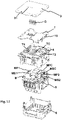
- the multi switch D comprises a key with three zones: A1 and A2 at two opposite ends and AC in the centre.
- the user-facing surface of the multi-switch should provide sensory indication differentiating the three zones.
- the surface could comprise a difference in tactile quality between adjacent zones, although they may also be visually marked out.
- the multiswitch is configured to allow a user to control one or more electric loads by compressing a key T in one of the three zones.
- Each zone is associated with an underlying microswitch respectively, MS1, MS2 and.
- MSC microswitch
- the multi-switch D comprises a base B and a key T articulated at two ends with respect to the base B by means of a first axis ⁇ 1 and a second axis ⁇ 2 parallel to the first axis ⁇ 1.
- the key T can perform a rotational movement with respect to it. That is, physically, the key is not articulated with the base B, but rather it is articulated with respect to walls W that are solidary with the base B. Said in other words, the walls and the base have a fixed relative position, they can be either made of separate parts that are joined, or they could even form part of a single molded part. In general, these walls W form the outer envelope of the switch.
- the invention deals with a key that could be considered as floating, and guided by some flexible elements, such as springs or flexible tabs, , and some retaining projections, to avoid its range of lateral and vertical movements, which are of interest to us for the purposes of the selective actuation that is the subject of this context.
- each axis ⁇ 1; ⁇ 2 comprises an unidirectional (this concept is well known in mechanics and has been explained above) connection 12, 14, 16, 18, such that the key T can:
- the activation angle ⁇ 1-act of the first end micro-switch MS1 is greater than the first activation angle ⁇ 1C-act of the central micro-switch MSC: ⁇ 1 C ⁇ act ⁇ ⁇ 1 ⁇ act
- the invention can be extended by including a second end micro switch MS2 located on the base B beneath the second zone A2 and comprising an actuation point MP2 as well.
- the key T comprises a second end point TP2 for directly or indirectly pressing the actuation point MP2 of the second end micro-switch MS2.
- the links are in the form of legs at two parallel edges of the key. The legs limit the outward displacement of the key but allow each or both edges of the key to be pressed towards the base B.
- the key T is by default urged away from the base B such that in the resting position, the interacting legs are in contact with one another.
- These retaining projections 14, 16 are materialized in walls W solidary to the base B.
- the multi-switch D comprises, as shown in figure 7 , one or more mechanical stops 20, 22, 24, 26, 30, 32, 34, 36, 38 configured to limit the rotation angle of the key T and/or to limit the downward displacement Z of the key T.
- the multi-switch further comprises an intensity indicator, in turn formed by light sources LED placed in the base B and light guides G embedded in the key T, with optionally the presence of light channels CL.
- the multi-switch also comprises a cover 3 configured to be directly pressed by a user and attached to the key T, the cover 3 preferably comprising through holes 31 for fitting the light guides G.
- the multi-switch D comprises an intermediate plate 4, placed between key T and the base B, the intermediate plate 4 comprising flexible tabs T1, T2, TC, such that the flexible tabs T1, T2, TC transmit the pressure from the end points TP1, TP2, TPC to the actuation points MP1, MP2, MPC.
- the flexible tabs T1, T2, TC also act as an element for urging the key towards a rest position.
- the key T comprises a plurality of reinforcement ribs TR that provides stiffness thereto, and therefore an accurate control of the micro-switches.
- a ratio endstop length / endstop height L_endstop / H_endstop comprised in the range [10; 27] provides for good dynamic results and that preferably the ratio endstop length / endstop height L_endstop / H_endstop is 20 and/or the endstop height H_endstop is comprised between 1.2 and 4 mm.
- the multi-switch comprises a lower plate 5 provided with electronic components and a lower cover 6.
- Fig. 4 shows a longitudinal cross-section of the multi-switch D in a resting position.
- the pairs of legs 12, 14 and 16, 18 will lose contact with one another if the key is moved downwards (without rotation).
- the central end point TPC begins to displace the central tab TC and hence this press the actuation point MPC of the central micro-switch MSC.
- the multi-switch is a dimmer for controlling light sources, so the effect of the activation of the central micro-switch is that a light is switched on or off.
- Fig. 5 shows a longitudinal cross-section of the dimmer D when a user presses the key T downwards in the left area causing the key T to tilt around the first axis.
- the first axis is formed by the pair of legs 16, 18.
- the key has practically reached the first activation angle ⁇ 1C-act of the central micro-switch MSC but has not reached the activation angle ⁇ 1-act of the first micro-switch MS1.
- the multi-switch is a dimmer, by pressing the first zone but not enough for reaching the activation angle ⁇ 1-act of the first micro-switch MS1, the central micro-switch is activated, and therefore the light is switched on or off as when the central zone is pressed.
- Fig. 6 shows a longitudinal cross-section of the multi-switch D when a user continues to press the key T downwards in the left zone. Eventually, the tilt angle of the key T reaches the activation angle ⁇ 1-act of the first micro-switch MS1.
- the activation of the first micro-switch MS1 changes the intensity of the light, which for instance may be increased.
Landscapes
- Rotary Switch, Piano Key Switch, And Lever Switch (AREA)
- Switch Cases, Indication, And Locking (AREA)
- Push-Button Switches (AREA)
Priority Applications (6)
| Application Number | Priority Date | Filing Date | Title |
|---|---|---|---|
| ES20383047T ES2965317T3 (es) | 2020-12-01 | 2020-12-01 | Interruptor múltiple |
| EP20383047.6A EP4009344B1 (de) | 2020-12-01 | 2020-12-01 | Mehrfachschalter |
| PL20383047.6T PL4009344T3 (pl) | 2020-12-01 | 2020-12-01 | Multiprzełącznik |
| CN202111419883.6A CN114582654A (zh) | 2020-12-01 | 2021-11-26 | 多重开关 |
| BR102021024066-0A BR102021024066A2 (pt) | 2020-12-01 | 2021-11-29 | Multicomutador |
| MX2021014621A MX2021014621A (es) | 2020-12-01 | 2021-11-29 | Interruptor multiple. |
Applications Claiming Priority (1)
| Application Number | Priority Date | Filing Date | Title |
|---|---|---|---|
| EP20383047.6A EP4009344B1 (de) | 2020-12-01 | 2020-12-01 | Mehrfachschalter |
Publications (3)
| Publication Number | Publication Date |
|---|---|
| EP4009344A1 true EP4009344A1 (de) | 2022-06-08 |
| EP4009344B1 EP4009344B1 (de) | 2023-09-13 |
| EP4009344C0 EP4009344C0 (de) | 2023-09-13 |
Family
ID=73834407
Family Applications (1)
| Application Number | Title | Priority Date | Filing Date |
|---|---|---|---|
| EP20383047.6A Active EP4009344B1 (de) | 2020-12-01 | 2020-12-01 | Mehrfachschalter |
Country Status (6)
| Country | Link |
|---|---|
| EP (1) | EP4009344B1 (de) |
| CN (1) | CN114582654A (de) |
| BR (1) | BR102021024066A2 (de) |
| ES (1) | ES2965317T3 (de) |
| MX (1) | MX2021014621A (de) |
| PL (1) | PL4009344T3 (de) |
Citations (2)
| Publication number | Priority date | Publication date | Assignee | Title |
|---|---|---|---|---|
| EP1182678A1 (de) * | 2000-08-23 | 2002-02-27 | Thomson Licensing S.A. | Schalter für die Handbetätigung von mehreren Schaltelementen |
| EP1619704A1 (de) * | 2004-07-21 | 2006-01-25 | Merten GmbH & Co. KG | Taster |
-
2020
- 2020-12-01 ES ES20383047T patent/ES2965317T3/es active Active
- 2020-12-01 PL PL20383047.6T patent/PL4009344T3/pl unknown
- 2020-12-01 EP EP20383047.6A patent/EP4009344B1/de active Active
-
2021
- 2021-11-26 CN CN202111419883.6A patent/CN114582654A/zh active Pending
- 2021-11-29 BR BR102021024066-0A patent/BR102021024066A2/pt unknown
- 2021-11-29 MX MX2021014621A patent/MX2021014621A/es unknown
Patent Citations (2)
| Publication number | Priority date | Publication date | Assignee | Title |
|---|---|---|---|---|
| EP1182678A1 (de) * | 2000-08-23 | 2002-02-27 | Thomson Licensing S.A. | Schalter für die Handbetätigung von mehreren Schaltelementen |
| EP1619704A1 (de) * | 2004-07-21 | 2006-01-25 | Merten GmbH & Co. KG | Taster |
Also Published As
| Publication number | Publication date |
|---|---|
| BR102021024066A2 (pt) | 2022-06-14 |
| ES2965317T3 (es) | 2024-04-12 |
| CN114582654A (zh) | 2022-06-03 |
| EP4009344B1 (de) | 2023-09-13 |
| PL4009344T3 (pl) | 2024-02-05 |
| EP4009344C0 (de) | 2023-09-13 |
| MX2021014621A (es) | 2022-06-02 |
Similar Documents
| Publication | Publication Date | Title |
|---|---|---|
| KR101025951B1 (ko) | 다방향 스위치 | |
| US4500758A (en) | Keyboard switch assembly having sensory feedback | |
| EP1950782B1 (de) | Elastisches glied für einen druckschalter | |
| EP1814130B1 (de) | Schiebeschalter | |
| KR20040043896A (ko) | 푸시버튼 | |
| US5317301A (en) | Joy stick | |
| US6774509B2 (en) | Electrical switch assembly | |
| EP4009344B1 (de) | Mehrfachschalter | |
| EP1369887A3 (de) | Multidirektionale Schaltvorrichtung und Multidirektionale Betätigungsvorrichtung welche diese verwendet | |
| CN103140907B (zh) | 电动座椅开关组件 | |
| JP7042034B2 (ja) | 反力発生部材及びキースイッチ装置 | |
| CA2437332A1 (en) | Depression switch and multidirectional input device | |
| US20010032776A1 (en) | Multidirectional switch device in which differnces in tactile feel are reduced | |
| CN1328738C (zh) | 带有操纵板的开关 | |
| CN210575663U (zh) | 键盘用按键装置 | |
| US20110089007A1 (en) | Mechanical button seamlessly integrated into a smooth surface | |
| CN100377021C (zh) | 具有快速跳出按钮的下沉式转换部件 | |
| EP1475816A1 (de) | Bedienungsschalter | |
| CN220399912U (zh) | 一种电动调节键盘软硬手感的键盘 | |
| JPH09213162A (ja) | 操作パネル | |
| JP2005032486A (ja) | 多方向入力装置 | |
| US9406463B2 (en) | Ergonomic foot switch | |
| JP4375243B2 (ja) | シーソースイッチ | |
| JPH0883532A (ja) | キースイッチのラバースプリング | |
| KR100572538B1 (ko) | 푸시 버튼 스위치용 반전 스프링 및 이를 사용한 푸시버튼 스위치 |
Legal Events
| Date | Code | Title | Description |
|---|---|---|---|
| PUAI | Public reference made under article 153(3) epc to a published international application that has entered the european phase |
Free format text: ORIGINAL CODE: 0009012 |
|
| STAA | Information on the status of an ep patent application or granted ep patent |
Free format text: STATUS: THE APPLICATION HAS BEEN PUBLISHED |
|
| AK | Designated contracting states |
Kind code of ref document: A1 Designated state(s): AL AT BE BG CH CY CZ DE DK EE ES FI FR GB GR HR HU IE IS IT LI LT LU LV MC MK MT NL NO PL PT RO RS SE SI SK SM TR |
|
| STAA | Information on the status of an ep patent application or granted ep patent |
Free format text: STATUS: REQUEST FOR EXAMINATION WAS MADE |
|
| 17P | Request for examination filed |
Effective date: 20220804 |
|
| RAV | Requested validation state of the european patent: fee paid |
Extension state: MA Effective date: 20220804 |
|
| RBV | Designated contracting states (corrected) |
Designated state(s): AL AT BE BG CH CY CZ DE DK EE ES FI FR GB GR HR HU IE IS IT LI LT LU LV MC MK MT NL NO PL PT RO RS SE SI SK SM TR |
|
| GRAP | Despatch of communication of intention to grant a patent |
Free format text: ORIGINAL CODE: EPIDOSNIGR1 |
|
| STAA | Information on the status of an ep patent application or granted ep patent |
Free format text: STATUS: GRANT OF PATENT IS INTENDED |
|
| RIC1 | Information provided on ipc code assigned before grant |
Ipc: G05G 9/047 20060101ALN20221123BHEP Ipc: H01H 25/04 20060101AFI20221123BHEP |
|
| INTG | Intention to grant announced |
Effective date: 20221215 |
|
| GRAJ | Information related to disapproval of communication of intention to grant by the applicant or resumption of examination proceedings by the epo deleted |
Free format text: ORIGINAL CODE: EPIDOSDIGR1 |
|
| STAA | Information on the status of an ep patent application or granted ep patent |
Free format text: STATUS: REQUEST FOR EXAMINATION WAS MADE |
|
| GRAP | Despatch of communication of intention to grant a patent |
Free format text: ORIGINAL CODE: EPIDOSNIGR1 |
|
| STAA | Information on the status of an ep patent application or granted ep patent |
Free format text: STATUS: GRANT OF PATENT IS INTENDED |
|
| INTC | Intention to grant announced (deleted) | ||
| RIC1 | Information provided on ipc code assigned before grant |
Ipc: G05G 9/047 20060101ALN20230417BHEP Ipc: H01H 25/04 20060101AFI20230417BHEP |
|
| INTG | Intention to grant announced |
Effective date: 20230510 |
|
| GRAS | Grant fee paid |
Free format text: ORIGINAL CODE: EPIDOSNIGR3 |
|
| GRAA | (expected) grant |
Free format text: ORIGINAL CODE: 0009210 |
|
| STAA | Information on the status of an ep patent application or granted ep patent |
Free format text: STATUS: THE PATENT HAS BEEN GRANTED |
|
| AK | Designated contracting states |
Kind code of ref document: B1 Designated state(s): AL AT BE BG CH CY CZ DE DK EE ES FI FR GB GR HR HU IE IS IT LI LT LU LV MC MK MT NL NO PL PT RO RS SE SI SK SM TR |
|
| REG | Reference to a national code |
Ref country code: CH Ref legal event code: EP |
|
| REG | Reference to a national code |
Ref country code: DE Ref legal event code: R096 Ref document number: 602020017595 Country of ref document: DE |
|
| REG | Reference to a national code |
Ref country code: IE Ref legal event code: FG4D |
|
| U01 | Request for unitary effect filed |
Effective date: 20231010 |
|
| U07 | Unitary effect registered |
Designated state(s): AT BE BG DE DK EE FI FR IT LT LU LV MT NL PT SE SI Effective date: 20231019 |
|
| REG | Reference to a national code |
Ref country code: MA Ref legal event code: VAGR Ref document number: 57585 Country of ref document: MA Kind code of ref document: B1 |
|
| U20 | Renewal fee paid [unitary effect] |
Year of fee payment: 4 Effective date: 20231120 |
|
| PG25 | Lapsed in a contracting state [announced via postgrant information from national office to epo] |
Ref country code: GR Free format text: LAPSE BECAUSE OF FAILURE TO SUBMIT A TRANSLATION OF THE DESCRIPTION OR TO PAY THE FEE WITHIN THE PRESCRIBED TIME-LIMIT Effective date: 20231214 |
|
| PG25 | Lapsed in a contracting state [announced via postgrant information from national office to epo] |
Ref country code: RS Free format text: LAPSE BECAUSE OF FAILURE TO SUBMIT A TRANSLATION OF THE DESCRIPTION OR TO PAY THE FEE WITHIN THE PRESCRIBED TIME-LIMIT Effective date: 20230913 Ref country code: NO Free format text: LAPSE BECAUSE OF FAILURE TO SUBMIT A TRANSLATION OF THE DESCRIPTION OR TO PAY THE FEE WITHIN THE PRESCRIBED TIME-LIMIT Effective date: 20231213 Ref country code: HR Free format text: LAPSE BECAUSE OF FAILURE TO SUBMIT A TRANSLATION OF THE DESCRIPTION OR TO PAY THE FEE WITHIN THE PRESCRIBED TIME-LIMIT Effective date: 20230913 Ref country code: GR Free format text: LAPSE BECAUSE OF FAILURE TO SUBMIT A TRANSLATION OF THE DESCRIPTION OR TO PAY THE FEE WITHIN THE PRESCRIBED TIME-LIMIT Effective date: 20231214 |
|
| PG25 | Lapsed in a contracting state [announced via postgrant information from national office to epo] |
Ref country code: IS Free format text: LAPSE BECAUSE OF FAILURE TO SUBMIT A TRANSLATION OF THE DESCRIPTION OR TO PAY THE FEE WITHIN THE PRESCRIBED TIME-LIMIT Effective date: 20240113 |
|
| REG | Reference to a national code |
Ref country code: ES Ref legal event code: FG2A Ref document number: 2965317 Country of ref document: ES Kind code of ref document: T3 Effective date: 20240412 |
|
| PGFP | Annual fee paid to national office [announced via postgrant information from national office to epo] |
Ref country code: ES Payment date: 20240102 Year of fee payment: 4 |
|
| PG25 | Lapsed in a contracting state [announced via postgrant information from national office to epo] |
Ref country code: SM Free format text: LAPSE BECAUSE OF FAILURE TO SUBMIT A TRANSLATION OF THE DESCRIPTION OR TO PAY THE FEE WITHIN THE PRESCRIBED TIME-LIMIT Effective date: 20230913 Ref country code: RO Free format text: LAPSE BECAUSE OF FAILURE TO SUBMIT A TRANSLATION OF THE DESCRIPTION OR TO PAY THE FEE WITHIN THE PRESCRIBED TIME-LIMIT Effective date: 20230913 Ref country code: IS Free format text: LAPSE BECAUSE OF FAILURE TO SUBMIT A TRANSLATION OF THE DESCRIPTION OR TO PAY THE FEE WITHIN THE PRESCRIBED TIME-LIMIT Effective date: 20240113 Ref country code: CZ Free format text: LAPSE BECAUSE OF FAILURE TO SUBMIT A TRANSLATION OF THE DESCRIPTION OR TO PAY THE FEE WITHIN THE PRESCRIBED TIME-LIMIT Effective date: 20230913 Ref country code: SK Free format text: LAPSE BECAUSE OF FAILURE TO SUBMIT A TRANSLATION OF THE DESCRIPTION OR TO PAY THE FEE WITHIN THE PRESCRIBED TIME-LIMIT Effective date: 20230913 |