EP4009224A1 - Reader/writer - Google Patents
Reader/writer Download PDFInfo
- Publication number
- EP4009224A1 EP4009224A1 EP20861312.5A EP20861312A EP4009224A1 EP 4009224 A1 EP4009224 A1 EP 4009224A1 EP 20861312 A EP20861312 A EP 20861312A EP 4009224 A1 EP4009224 A1 EP 4009224A1
- Authority
- EP
- European Patent Office
- Prior art keywords
- reader
- angle
- writer
- card
- intersection angle
- Prior art date
- Legal status (The legal status is an assumption and is not a legal conclusion. Google has not performed a legal analysis and makes no representation as to the accuracy of the status listed.)
- Withdrawn
Links
Images




Classifications
-
- G—PHYSICS
- G06—COMPUTING OR CALCULATING; COUNTING
- G06K—GRAPHICAL DATA READING; PRESENTATION OF DATA; RECORD CARRIERS; HANDLING RECORD CARRIERS
- G06K7/00—Methods or arrangements for sensing record carriers, e.g. for reading patterns
- G06K7/0013—Methods or arrangements for sensing record carriers, e.g. for reading patterns by galvanic contacts, e.g. card connectors for ISO-7816 compliant smart cards or memory cards, e.g. SD card readers
- G06K7/0021—Methods or arrangements for sensing record carriers, e.g. for reading patterns by galvanic contacts, e.g. card connectors for ISO-7816 compliant smart cards or memory cards, e.g. SD card readers for reading/sensing record carriers having surface contacts
-
- G—PHYSICS
- G06—COMPUTING OR CALCULATING; COUNTING
- G06K—GRAPHICAL DATA READING; PRESENTATION OF DATA; RECORD CARRIERS; HANDLING RECORD CARRIERS
- G06K7/00—Methods or arrangements for sensing record carriers, e.g. for reading patterns
- G06K7/0008—General problems related to the reading of electronic memory record carriers, independent of its reading method, e.g. power transfer
-
- G—PHYSICS
- G06—COMPUTING OR CALCULATING; COUNTING
- G06K—GRAPHICAL DATA READING; PRESENTATION OF DATA; RECORD CARRIERS; HANDLING RECORD CARRIERS
- G06K7/00—Methods or arrangements for sensing record carriers, e.g. for reading patterns
- G06K7/0013—Methods or arrangements for sensing record carriers, e.g. for reading patterns by galvanic contacts, e.g. card connectors for ISO-7816 compliant smart cards or memory cards, e.g. SD card readers
-
- G—PHYSICS
- G06—COMPUTING OR CALCULATING; COUNTING
- G06K—GRAPHICAL DATA READING; PRESENTATION OF DATA; RECORD CARRIERS; HANDLING RECORD CARRIERS
- G06K7/00—Methods or arrangements for sensing record carriers, e.g. for reading patterns
- G06K7/0013—Methods or arrangements for sensing record carriers, e.g. for reading patterns by galvanic contacts, e.g. card connectors for ISO-7816 compliant smart cards or memory cards, e.g. SD card readers
- G06K7/0056—Methods or arrangements for sensing record carriers, e.g. for reading patterns by galvanic contacts, e.g. card connectors for ISO-7816 compliant smart cards or memory cards, e.g. SD card readers housing of the card connector
-
- G—PHYSICS
- G06—COMPUTING OR CALCULATING; COUNTING
- G06K—GRAPHICAL DATA READING; PRESENTATION OF DATA; RECORD CARRIERS; HANDLING RECORD CARRIERS
- G06K7/00—Methods or arrangements for sensing record carriers, e.g. for reading patterns
- G06K7/01—Details
- G06K7/015—Aligning or centering of the sensing device with respect to the record carrier
-
- G—PHYSICS
- G06—COMPUTING OR CALCULATING; COUNTING
- G06K—GRAPHICAL DATA READING; PRESENTATION OF DATA; RECORD CARRIERS; HANDLING RECORD CARRIERS
- G06K7/00—Methods or arrangements for sensing record carriers, e.g. for reading patterns
- G06K7/10—Methods or arrangements for sensing record carriers, e.g. for reading patterns by electromagnetic radiation, e.g. optical sensing; by corpuscular radiation
- G06K7/10009—Methods or arrangements for sensing record carriers, e.g. for reading patterns by electromagnetic radiation, e.g. optical sensing; by corpuscular radiation sensing by radiation using wavelengths larger than 0.1 mm, e.g. radio-waves or microwaves
-
- G—PHYSICS
- G06—COMPUTING OR CALCULATING; COUNTING
- G06K—GRAPHICAL DATA READING; PRESENTATION OF DATA; RECORD CARRIERS; HANDLING RECORD CARRIERS
- G06K7/00—Methods or arrangements for sensing record carriers, e.g. for reading patterns
- G06K7/10—Methods or arrangements for sensing record carriers, e.g. for reading patterns by electromagnetic radiation, e.g. optical sensing; by corpuscular radiation
- G06K7/10009—Methods or arrangements for sensing record carriers, e.g. for reading patterns by electromagnetic radiation, e.g. optical sensing; by corpuscular radiation sensing by radiation using wavelengths larger than 0.1 mm, e.g. radio-waves or microwaves
- G06K7/10366—Methods or arrangements for sensing record carriers, e.g. for reading patterns by electromagnetic radiation, e.g. optical sensing; by corpuscular radiation sensing by radiation using wavelengths larger than 0.1 mm, e.g. radio-waves or microwaves the interrogation device being adapted for miscellaneous applications
-
- G—PHYSICS
- G06—COMPUTING OR CALCULATING; COUNTING
- G06K—GRAPHICAL DATA READING; PRESENTATION OF DATA; RECORD CARRIERS; HANDLING RECORD CARRIERS
- G06K7/00—Methods or arrangements for sensing record carriers, e.g. for reading patterns
- G06K7/10—Methods or arrangements for sensing record carriers, e.g. for reading patterns by electromagnetic radiation, e.g. optical sensing; by corpuscular radiation
- G06K7/10009—Methods or arrangements for sensing record carriers, e.g. for reading patterns by electromagnetic radiation, e.g. optical sensing; by corpuscular radiation sensing by radiation using wavelengths larger than 0.1 mm, e.g. radio-waves or microwaves
- G06K7/10366—Methods or arrangements for sensing record carriers, e.g. for reading patterns by electromagnetic radiation, e.g. optical sensing; by corpuscular radiation sensing by radiation using wavelengths larger than 0.1 mm, e.g. radio-waves or microwaves the interrogation device being adapted for miscellaneous applications
- G06K7/10415—Methods or arrangements for sensing record carriers, e.g. for reading patterns by electromagnetic radiation, e.g. optical sensing; by corpuscular radiation sensing by radiation using wavelengths larger than 0.1 mm, e.g. radio-waves or microwaves the interrogation device being adapted for miscellaneous applications the interrogation device being fixed in its position, such as an access control device for reading wireless access cards, or a wireless ATM
Definitions
- An embodiment of the present invention relates to a reader/writer.
- a stationary reader/writer that reads from and writes on a contact type or non-contact type IC card.
- a reader/writer installed at a counter or the like of a store reads and writes information when an IC card held in a person's hand is inserted into or put over a predetermined portion thereof.
- Patent Document 1 Japanese Unexamined Patent Application, First Publication No. 2017-117337
- a problem to be solved by the present invention is to provide a reader/writer in which unnaturalness of motions required for reading from and writing on an information storage medium can be suppressed.
- a reader/writer includes an insertion portion and a support member.
- An information storage medium held by a person with fingers is inserted into the insertion portion.
- the support member supports the insertion portion on an installation surface by causing an insertion direction of the information storage medium with respect to the insertion portion to be lowered to the front to intersect with a horizontal plane.
- an intersection angle between the insertion direction and the horizontal plane is set to a predetermined acute angle at which the fingers of the person do not interfere with the installation surface when the information storage medium is inserted into the insertion portion.
- FIG. 1 is a view schematically showing a disposition state of a reader/writer 10 of the embodiment.
- the reader/writer 10 is installed on, for example, an installation surface 11A of an installation table 11 such as a counter in a store.
- the installation surface 11A is an upper end surface of the installation table 11 in a vertical direction.
- the installation surface 11A is a horizontal plane parallel to a horizontal direction.
- the installation table 11 is disposed on a horizontal reference surface 12.
- a height H of the installation surface 11A from the reference surface 12 in the vertical direction is a predetermined height.
- the reader/writer 10 reads information or reads and writes information on an information storage medium 13.
- the information storage medium 13 is an integrated circuit (IC) card 14.
- the IC card 14 is held by a person 15 with fingers 16 to be brought toward and away from the reader/writer 10.
- FIG. 2 is a view showing an example of a first holding method of the IC card 14 inserted into the reader/writer 10 of the embodiment.
- FIG. 3 is a view showing an example of a second holding method of the IC card 14 inserted into the reader/writer 10 of the embodiment.
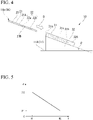
- FIG. 4 is a view showing an insertion direction D of the IC card 14 with respect to the reader/writer 10 of the embodiment.
- the reader/writer 10 may handle the contact type IC card 14a (14).
- the contact type IC card 14a includes a support base 21, and an IC module 22 and a biometric authentication sensor 23 provided on the support base 21.
- the support base 21 is formed of a resin material into a rectangular plate shape.
- the IC module 22 includes an IC chip 22a disposed inside the support base 21, and a contact 22b provided on a first surface 21A of both sides (first surface 21A and second surface 21B) of the support base 21 in a thickness direction.
- the IC chip 22a includes a read-only memory (ROM), a random access memory (RAM), and a central processing unit (CPU).
- the ROM is a non-volatile memory such as an electrically erasable programmable read-only memory (EEPROM) or a flash ROM that holds information in the absence of power supply.
- the biometric authentication sensor 23 is, for example, a fingerprint sensor.
- the biometric authentication sensor 23 is exposed on the first surface 21A of both sides (the first surface 21A and the second surface 21B) of the support base 21 in the thickness direction.
- the biometric authentication sensor 23 detects a fingerprint of a thumb 16a, an index finger 16b, or the like among the fingers 16 of the person 15.
- the biometric authentication sensor 23 performs fingerprint authentication using detected data of fingerprints and fingerprint data stored in advance.
- the IC card 14a is sandwiched by the thumb 16a and the index finger 16b from both sides in the thickness direction, and the thumb 16a supports the IC card 14a from above in the vertical direction.
- the biometric authentication sensor 23 performs fingerprint authentication of the thumb 16a on the first surface 21A side of the IC card 14a.
- the IC card 14a is sandwiched by the thumb 16a and the index finger 16b from both sides in the thickness direction, and the thumb 16a supports the IC card 14a from below in the vertical direction.
- the biometric authentication sensor 23 performs fingerprint authentication of the index finger 16b on the first surface 21A side of the IC card 14a.
- the reader/writer 10 includes an insertion portion 31 and a support member 32 that supports the insertion portion 31.
- An outer shape of the insertion portion 31 may be, for example, a rectangular plate shape.
- An insertion slot 31a into which the IC card 14a is inserted is formed in the insertion portion 31.
- the insertion portion 31 includes, for example, a control device 31b and a terminal 31c that is brought into contact with the contact 22b of the contact type IC card 14a.
- the control device 31b is a software function unit that functions when a predetermined program is executed by a processor such as a CPU.
- the software function unit is an electronic control unit (ECU) including a processor such as a CPU, a ROM for storing a program, a RAM for temporarily storing data, and various electronic circuits. At least a part of the control device 31b may include an integrated circuit such as a large scale integration (LSI).
- LSI large scale integration
- the control device 31b controls transfer of information and power supply via the terminal 31c that comes into contact with the contact 22b of the contact type IC card 14a inserted into the insertion slot 31a.
- An outer shape of the support member 32 is, for example, an inclined table shape.
- the support member 32 is installed on the installation surface 11A of the installation table 11.
- the support member 32 has a flat inclined surface 32A that supports the insertion portion 31.
- the inclined surface 32A intersects the horizontal plane at an acute angle.
- the inclined surface 32A supports the insertion portion 31 with the insertion slot 31a of the insertion portion 31 facing obliquely upward with respect to the vertical direction.
- the insertion direction D of the IC card 14a with respect to the insertion portion 31 disposed on the inclined surface 32A is set to be lowered to the front.
- An intersection angle (first intersection angle) ⁇ of the insertion direction D with respect to the horizontal plane is the same as an intersection angle between the inclined surface 32A and the horizontal plane.
- the first intersection angle ⁇ is a predetermined acute angle at which the fingers 16 of the person 15 do not interfere with the installation surface 11A when the IC card 14a is inserted into the insertion portion 31.
- the predetermined acute angle may be, for example, a constant angle in a range of 20 degrees or more and less than 90 degrees.
- the support member 32 in which the insertion portion 31 is inclined so that the fingers 16 of the person 15 do not interfere with the installation surface 11A when the IC card 14a is inserted into the insertion portion 31 is provided. Therefore, unnaturalness of a motion and posture of a wrist 17 of the person 15 can be suppressed.
- the reader/writer 10 includes the support member 32 that handles the first holding method and the second holding method. Therefore, even when insertion of the IC card 14a is performed in parallel with the fingerprint authentication by the biometric authentication sensor 23, unnaturalness of a motion and posture of the wrist 17 of the person 15 can be suppressed.
- the reader/writer 10 has the support member 32 that causes the intersection angle ⁇ of the insertion direction D with respect to the horizontal plane to be 20 degrees or more. Therefore, the IC card 14a can be inserted into the insertion portion 31 by a natural motion and posture of the fingers 16 and the wrist 17 of the person 15.
- the intersection angle (the first intersection angle) ⁇ of the insertion direction D with respect to the horizontal plane has been described as a constant predetermined acute angle, but the present invention is not limited thereto.
- the first intersection angle ⁇ may be changed according to a predetermined parameter.
- FIG. 5 is a graph showing an example of a correspondence relationship between the height H of the installation surface 11A on which the reader/writer 10 of a first modified example of the embodiment is installed and the intersection angle (the first intersection angle) ⁇ of the insertion direction D of the IC card 14a into the reader/writer 10 with respect to the horizontal plane.
- the first intersection angle ⁇ has a relationship in which the first intersection angle ⁇ decreases as the height H of the installation surface 11A from the reference surface 12 in the vertical direction increases.
- the first intersection angle ⁇ has a relationship in which the first intersection angle ⁇ gradually decreases from a second acute angle ⁇ 2 to the first acute angle ⁇ 1 ( ⁇ ⁇ 2) as the height H increases from a first height H1 to a second height H2 (> H1).
- the reader/writer 10 of the first modified example has the support member 32 whose intersection angle ⁇ changes according to the height H of the installation surface 11A. Therefore, the IC card 14a can be inserted into the insertion portion 31 by a natural motion and posture of the fingers 16 and the wrist 17 of the person 15 regardless of the height H of the installation surface 11A.
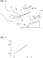
- FIG. 6 is a view showing an example of a third holding method of the IC card 14b that is put over a reader/writer 10a in a second modified example of the embodiment.
- FIG. 7 is a graph showing an example of a correspondence relationship between the height H of the installation surface 11A on which the reader/writer 10a of the second modified example of the embodiment is installed and an intersection angle (a second intersection angle) ⁇ a of a reading surface 51A of the reader/writer 10a with respect to the horizontal plane.
- the reader/writer 10a in the second modified example of the embodiment handles the non-contact type IC card 14b.
- the non-contact type IC card 14b includes the support base 21, and an IC module 41 and the biometric authentication sensor 23 provided on the support base 21.
- the IC module 41 includes an IC chip 41a and an antenna (card-side antenna) 41b disposed inside the support base 21.
- the IC chip 41a includes a ROM, a RAM, and a CPU.
- the ROM is a non-volatile memory such as an EEPROM or a flash ROM that holds information in the absence of power supply.
- the antenna 41b is a metal wire having a predetermined shape.
- the IC card 14b is sandwiched by the thumb 16a and the index finger 16b from both sides in the thickness direction, and the thumb 16a supports the IC card 14b from above in the vertical direction.
- the biometric authentication sensor 23 performs fingerprint authentication of the thumb 16a on the first surface 21A side of the IC card 14b.
- the reader/writer 10a of the second modified example of the embodiment includes a main body 51 having the reading surface 51A and a support member 52 for supporting the main body 51.
- An outer shape of the main body 51 may be, for example, a rectangular plate shape.
- the main body 51 includes the reading surface 51A over which the IC card 14b is put, a control device 51a, and an antenna (reader-side antenna) 51b.
- the control device 51a is a software function unit that functions when a predetermined program is executed by a processor such as a CPU.
- the software function unit is an ECU including a processor such as a CPU, a ROM for storing a program, a RAM for temporarily storing data, and various electronic circuits. At least a part of the control device 51a may include an integrated circuit such as an LSI.
- the antenna 51b is a metal wire having a predetermined shape.
- the control device 51a controls transfer of information and power supply via the antenna (reader-side antenna) 51b that performs transmission and reception with the antenna (card-side antenna) 41b of the non-contact type IC card 14b that is put over the reading surface 51A.
- An outer shape of the support member 52 is, for example, an inclined table shape.
- the support member 52 is installed on the installation surface 11A of the installation table 11.
- the support member 52 has a flat inclined surface 52A for supporting the main body 51.
- the inclined surface 52A intersects the horizontal plane at an acute angle.
- the reading surface 51A of the main body 51 disposed on the inclined surface 52A is set to be inclined upward to the front.
- the intersection angle (the second intersection angle) ⁇ a between the reading surface 51A and the horizontal plane is the same as an intersection angle between the inclined surface 52A and the horizontal plane.
- the second intersection angle ⁇ a is a predetermined acute angle which is configured so that an angle change from an angle of the wrist 17 of the person 15 at the time of a reference posture in a relaxed state to an angle of the wrist 17 when the IC card 14b is put over the reading surface 51A is within a predetermined angle range.
- the reference posture in a relaxed state refers to a natural posture of the body in which strength in arms and the wrists 17 is made to leave (in a relaxed state) and the arms are hung down.
- the predetermined angle range is, for example, in a range of ⁇ 5 degrees in posture change corresponding to a motion such as bending and stretching from the reference posture of the wrist 17 in the relaxed state.
- the predetermined acute angle is a constant angle in a range of, for example, 20 degrees or more and less than 90 degrees, or changes according to a predetermined parameter.
- the second intersection angle ⁇ a increases as the height H of the installation surface 11A from the reference surface 12 in the vertical direction increases.
- the second intersection angle ⁇ a gradually increases from the first acute angle ⁇ a1 to the second acute angle ⁇ a2 (> ⁇ a1) as the height H increases from the first height H1 to the second height H2 (> H1).
- the reader/writer 10a of the second modified example has the support member 52 in which the main body 51 is inclined so that an angle change from an angle of the wrist 17 of the person 15 at the time of the reference posture in the relaxed state to an angle of the wrist 17 when the IC card 14b is put over the reading surface 51A is within the predetermined angle range. Therefore, unnaturalness of a motion and posture of the wrist 17 of the person 15 can be suppressed.
- the reader/writer 10a of the second modified example has the support member 52 in which the predetermined angle range is set in a range of ⁇ 5 degrees in posture change corresponding to a motion such as bending and stretching from the reference posture of the wrist 17 in the relaxed state. Therefore, the IC card 14b can be put over the reading surface 51A by a natural motion and posture of the fingers 16 and the wrist 17 of the person 15.
- the reader/writer 10a of the second modified example has a support member 52 that handles the third holding method. Therefore, even when putting-over of the IC card 14b is performed in parallel with the fingerprint authentication by the biometric authentication sensor 23, unnaturalness of a motion and posture of the wrist 17 of the person 15 can be suppressed.
- the reader/writer 10a of the second modified example has the support member 52 whose intersection angle ⁇ a changes according to the height H of the installation surface 11A. Therefore, the IC card 14b can be put over the reading surface 51A by a natural motion and posture of the fingers 16 and the wrist 17 of the person 15 regardless of the height H of the installation surface 11A.
- the reader/writer 10a has been described as corresponding to the third holding method of the non-contact type IC card 14b, but the present invention is not limited thereto.
- the reader/writer 10a may handle a fourth holding method of the non-contact type IC card 14b.
- FIG. 8 is a view showing an example of the fourth holding method of the IC card 14b that is put over the reader/writer 10b of the third modified example of the embodiment.
- FIG. 9 is a graph showing an example of a correspondence relationship between the height H of the installation surface 11A on which the reader/writer 10b of the third modified example of the embodiment is installed and an intersection angle (a third intersection angle) ⁇ b of the reading surface 51A of the reader/writer 10b with respect to the horizontal plane.
- the IC card 14b is sandwiched by the thumb 16a and the index finger 16b from both sides in the thickness direction, and the thumb 16a supports the IC card 14b from below in the vertical direction.
- the biometric authentication sensor 23 performs fingerprint authentication of the index finger 16b on the first surface 21A side of the IC card 14b.
- the reading surface 51A of the main body 51 disposed on the inclined surface 52A is set to be lowered to the front.
- the intersection angle (the third intersection angle) ⁇ b between the reading surface 51A and the horizontal plane is the same as the intersection angle between the inclined surface 52A and the horizontal plane.
- the third intersection angle ⁇ b is a predetermined acute angle which is configured so that an angle change from an angle of the wrist 17 of the person 15 at the time of the reference posture in the relaxed state to an angle of the wrist 17 when the IC card 14b is put over the reading surface 51A is within a predetermined angle range.
- the predetermined angle range is, for example, in a range of ⁇ 5 degrees in posture change corresponding to a motion such as bending and stretching from the reference posture of the wrist 17 in the relaxed state.
- the predetermined acute angle is a constant angle in a range of, for example, 20 degrees or more and less than 90 degrees, or changes according to a predetermined parameter.
- the third intersection angle ⁇ b decreases as the height H of the installation surface 11A from the reference surface 12 in the vertical direction increases.
- the third intersection angle ⁇ b gradually decreases from the second acute angle ⁇ b2 to the first acute angle ⁇ b1 ( ⁇ ⁇ b2) as the height H increases from the first height H1 to the second height H2 (> H1).
- the reader/writer 10b of the third modified example has the support member 52 that handles the fourth holding method. Therefore, even when putting-over of the IC card 14b is performed in parallel with the fingerprint authentication by the biometric authentication sensor 23, unnaturalness of a motion and posture of the wrist 17 of the person 15 can be suppressed.
- the reader/writer 10b of the third modified example has the support member 52 in which the main body 51 is inclined so that an angle change at the time of putting the IC card 14b over the reading surface 51A from the reference posture of the wrist 17 of the person 15 in the relaxed state is within the predetermined angle range. Therefore, a natural motion and posture of the wrist 17 of the person 15 can be promoted.
- the reader/writer 10b has the support member 52 whose intersection angle ⁇ b changes according to the height H of the installation surface 11A. Therefore, the IC card 14b can be put over the reading surface 51A by a natural motion and posture of the fingers 16 and the wrist 17 of the person 15 regardless of the height H of the installation surface 11A.
- the reader/writer 10 has been described as having the support member 32 or 52 in which the intersection angle ⁇ , ⁇ a, or ⁇ b of the inclined surface 32A or 52A with respect to the horizontal plane is constant, but the present invention is not limited thereto.
- the reader/writer 10 may include an angle changing mechanism for changing the intersection angle ⁇ , ⁇ a, or ⁇ b.
- the angle changing mechanism may be a ball joint mechanism, a ratchet mechanism, or the like.
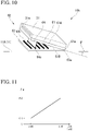
- FIG. 10 is a perspective view schematically showing a configuration of the reader/writer 10b of a fourth modified example of the embodiment.
- the reader/writer 10b includes the insertion portion 31, a support member 61 that supports the insertion portion 31, and an angle changing mechanism 62 that changes an intersection angle (inclination) of the support member 61 with respect to the horizontal plane.
- An outer shape of the support member 61 is, for example, a rectangular plate.
- the support member 61 has a flat inclined surface 61A that supports the insertion portion 31.
- the inclined surface 61A intersects the horizontal plane at an acute angle by the angle changing mechanism 62.
- the inclined surface 61A supports the insertion portion 31 with the insertion slot 31a of the insertion portion 31 facing obliquely upward with respect to the vertical direction.
- the angle changing mechanism 62 includes a bottom portion 63 and a stand member 64 that is engaged with the bottom portion 63.
- An outer shape of the bottom portion 63 is, for example, a plate shape.
- the bottom portion 63 is installed on the installation surface 11A of the installation table 11.
- the bottom portion 63 includes a connection member 63a.
- the connection member 63a may be, for example, a hinge or the like.
- the connection member 63a is connected to an end portion 61a of the support member 61.
- the support member 61 rotates around the end portion 61a connected to the connection member 63a.
- a plurality of positioning portions 63b are formed on a surface of the bottom portion 63.
- An outer shape of the positioning portions 63b is, for example, a recessed shape or a protruding shape.
- the positioning portion 63b each fix a distal end portion 64a of the stand member 64 by coming into contact with the distal end portion 64a.
- An outer shape of the stand member 64 is, for example, a rectangular plate shape.
- a base end portion (not shown) of the stand member 64 is connected to a surface 61B on a side of both sides of the support member 61 in the thickness direction opposite to the inclined surface 61A by, for example, a connection member (not shown) such as a hinge.
- the stand member 64 rotates around the base end portion (not shown) connected to the connection member (not shown).
- the angle changing mechanism 62 changes an intersection angle of the inclined surface 61A of the support member 61 with respect to the horizontal plane by changing the positioning portion 63b in contact with the distal end portion 64a of the stand member 64.
- the insertion direction D of the IC card 14a with respect to the insertion portion 31 disposed on the inclined surface 61A of the support member 61 is set to be lowered to the front.
- An intersection angle (first intersection angle) ⁇ of the insertion direction D with respect to the horizontal plane is the same as the intersection angle between the inclined surface 61A and the horizontal plane.
- the first intersection angle ⁇ is a predetermined acute angle at which the fingers 16 of the person 15 do not interfere with the installation surface 11A when the IC card 14a is inserted into the insertion portion 31.
- the reader/writer 10b of the fourth modified example has the angle changing mechanism 62 that changes the intersection angle between the inclined surface 61A and the horizontal plane. Therefore, a natural motion and posture of the fingers 16 and the wrist 17 holding the IC card 14a can be easily promoted.
- the first intersection angle ⁇ has been described as being changed according to the height H of the installation surface 11A from the reference surface 12 in the vertical direction, but the present invention is not limited thereto.
- the intersection angles between the inclined surfaces 32A, 52A, and 61A and the horizontal plane in the above-described embodiment and modified examples may be changed according to a plurality of predetermined parameters.
- FIG. 11 is a graph showing an example of a correspondence relationship between the height H of the installation surface 11A on which the reader/writer 10 of a fifth modified example of the embodiment is installed, a body height h of the person 15 of the IC card 14, and an intersection angle (first intersection angle) ⁇ of the insertion direction D of the IC card 14 into the reader/writer 10 with respect to the horizontal plane.
- the body height h is, for example, an average body height or the like of a plurality of persons 15.
- the first intersection angle ⁇ gradually increases from a first acute angle ⁇ 1 to a second acute angle ⁇ 2 (> ⁇ 1) as the difference ⁇ H increases from a first predetermined value ⁇ H1 to a second predetermined value ⁇ H2 (> ⁇ H1).
- the reader/writer 10b in the fifth modified example has the support member 32 whose intersection angle ⁇ changes according to the body height h of the person 15 and the height H of the installation surface 11A. Therefore, a natural motion and posture of the fingers 16 and the wrist 17 of the person 15 can be promoted regardless of the body height h of the person 15 and the height H of the installation surface 11A.
- the reader/writer 10 has been described as being installed on the installation surface 11A of the installation table 11, but the present invention is not limited thereto.
- the reader/writer 10 may be installed on a surface of a support portion provided on the installation table 11.
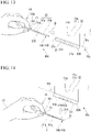
- FIG. 12 is a view schematically showing a disposition state of a reader/writer 10c of a sixth modified example of the embodiment.
- FIG. 13 is a view showing an example of a fifth holding method of the IC card 14 inserted into the reader/writer 10c of the sixth modified example of the embodiment.
- FIG. 14 is a view showing an example of the fifth holding method of the IC card 14 that is put over the reader/writer 10c of the sixth modified example of the embodiment.
- FIG. 12 is a view schematically showing a disposition state of a reader/writer 10c of a sixth modified example of the embodiment.
- FIG. 13 is a view showing an example of a fifth holding method of the IC card 14 inserted into the reader/writer 10c of the sixth modified example of the embodiment.
- FIG. 14 is a view showing an example of the fifth holding method of the IC card 14 that is put over the reader/writer 10c of the sixth modified example of the embodiment.
- FIG. 12 is a view schematically showing a disposition state of a reader
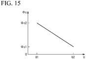
- 15 is a graph showing an example of a correspondence relationship between a height U of an installation surface 71A on which the reader/writer 10c of the sixth modified example of the embodiment is installed and an intersection angle (fourth intersection angle) ⁇ c of the insertion direction D of the IC card 14 into the reader/writer 10c or the reading surface 51A of the reader/writer 10c with respect to the horizontal plane.
- the reader/writer 10c is installed on the installation surface 71A of a support portion 71 provided on the installation table 11.
- An outer shape of the support portion 71 is, for example, a rod shape bent in an L shape.
- the installation surface 71A of the support portion 71 is, for example, a surface facing downward at a distal end portion of an arm portion 71b that protrudes in a horizontal direction from an upper end portion of a leg portion 71a extending in the vertical direction.
- the height U of the installation surface 71A from the reference surface 12 in the vertical direction is a predetermined height.
- the reader/writer 10c of the sixth modified example of the embodiment includes the insertion portion 31 or the main body 51, and the support member 32.
- the support member 32 is installed on the installation surface 71A of the support portion 71.
- the support member 32 includes the flat inclined surface 32A that supports the insertion portion 31 or the main body 51.
- the inclined surface 32A intersects the horizontal plane at an acute angle.
- the inclined surface 32A supports the insertion portion 31 with the insertion slot 31a of the insertion portion 31 facing obliquely upward with respect to the vertical direction.
- the insertion direction D of the IC card 14a with respect to the insertion portion 31 disposed on the inclined surface 32A is set to be lowered to the front.
- the inclined surface 32A supports the main body 51 by setting the reading surface 51A of the main body 51 to be lowered to the front.
- the IC card 14 (14a and 14b) is sandwiched by the thumb 16a and the index finger 16b from both sides in the thickness direction, and the thumb 16a supports the IC card 14 from below in the vertical direction.
- the biometric authentication sensor 23 performs fingerprint authentication of the index finger 16b on the first surface 21A side of the IC card 14.
- the intersection angle (fourth intersection angle) ⁇ c of the insertion direction D of the IC card 14a with respect to the horizontal plane is the same as an intersection angle between the inclined surface 32A and the horizontal plane.
- the fourth intersection angle ⁇ c is a predetermined acute angle at which the fingers 16 of the person 15 do not interfere with the installation surface 71A when the IC card 14a is inserted into the insertion portion 31.
- the intersection angle (fourth intersection angle) ⁇ c between the reading surface 51A and the horizontal plane is the same as the intersection angle between the inclined surface 32A and the horizontal plane.
- the fourth intersection angle ⁇ c is a predetermined acute angle configured so that an angle change at the time of putting the IC card 14b over the reading surface 51A from the reference posture of the wrist 17 of the person 15 in the relaxed state is within a predetermined angle range.
- the predetermined angle range is, for example, in a range of ⁇ 5 degrees in posture change corresponding to a motion such as bending and stretching from the reference posture of the wrist 17 in the relaxed state.
- the fourth intersection angle ⁇ c has a relationship in which the fourth intersection angle ⁇ c decreases as the height U of the installation surface 71A from the reference surface 12 in the vertical direction increases.
- the fourth intersection angle ⁇ c gradually decreases from a second acute angle ⁇ c2 to a first acute angle ⁇ c1 ( ⁇ ⁇ c2) as the height U increases from a first height U1 to a second height U2 (> U1).
- the reader/writer 10c in the sixth modified example has the support member 32 in which the insertion portion 31 is inclined so that the fingers 16 of the person 15 do not interfere with the installation surface 11A when the IC card 14a is inserted into the insertion portion 31. Therefore, unnaturalness of a motion and posture of the wrist 17 of the person 15 can be suppressed.
- the reader/writer 10c has the support member 32 in which the main body 51 is inclined so that an angle change from an angle of the wrist 17 of the person 15 at the time of the reference posture in the relaxed state to an angle of the wrist 17 when the IC card 14b is put over the reading surface 51A is within the predetermined angle range. Therefore, unnaturalness of a motion and posture of the wrist 17 of the person 15 can be suppressed.
- the reader/writer 10c has the support member 32 whose intersection angle ⁇ changes according to the height U of the installation surface 71A. Therefore, a natural motion and posture of the fingers 16 and the wrist 17 of the person 15 can be promoted regardless of the height U of the installation surface 71A.
- the insertion portion 31 of the reader/writer 10 has been described as handling the contact type IC card 14a, but the present invention is not limited thereto.
- the insertion portion 31 of the reader/writer 10 may handle the non-contact type IC card 14b.
- the insertion portion 31 handling the non-contact type IC card 14b includes an antenna (reader-side antenna) that performs transmission and reception with an antenna (card-side antenna) of the IC card 14b.
- the control device 31b of the insertion portion 31 controls transfer of information and power supply via the antenna (reader-side antenna) that performs transmission and reception with the antenna (card-side antenna) of the non-contact type IC card 14b that is inserted into the insertion slot 31a.
- the IC chips 22a and 41a of the IC card 14 have been described as including a CPU, but the present invention is not limited thereto, and the CPU may be omitted.
- the support members 32, 52, and 61 having the inclined surfaces 32A, 52A, and 61A intersecting the horizontal plane at a predetermined acute angle are provided, a natural motion and posture of the fingers 16 and the wrist 17 of the person 15 can be promoted when the IC card 14 is inserted or put over.
Landscapes
- Engineering & Computer Science (AREA)
- Physics & Mathematics (AREA)
- Artificial Intelligence (AREA)
- Theoretical Computer Science (AREA)
- General Physics & Mathematics (AREA)
- Computer Vision & Pattern Recognition (AREA)
- Toxicology (AREA)
- Health & Medical Sciences (AREA)
- General Health & Medical Sciences (AREA)
- Electromagnetism (AREA)
- Computer Networks & Wireless Communication (AREA)
- Credit Cards Or The Like (AREA)
- Measurement Of The Respiration, Hearing Ability, Form, And Blood Characteristics Of Living Organisms (AREA)
- Conveying Record Carriers (AREA)
Abstract
Description
- An embodiment of the present invention relates to a reader/writer.
- Conventionally, a stationary reader/writer that reads from and writes on a contact type or non-contact type IC card is known. For example, a reader/writer installed at a counter or the like of a store reads and writes information when an IC card held in a person's hand is inserted into or put over a predetermined portion thereof.
- However, if a position and posture of the predetermined portion on the reader/writer are inappropriate, it may be difficult for the person to move his or her wrist naturally.
- [Patent Document 1]
Japanese Unexamined Patent Application, First Publication No. 2017-117337 - A problem to be solved by the present invention is to provide a reader/writer in which unnaturalness of motions required for reading from and writing on an information storage medium can be suppressed.
- According to one embodiment, a reader/writer includes an insertion portion and a support member. An information storage medium held by a person with fingers is inserted into the insertion portion. The support member supports the insertion portion on an installation surface by causing an insertion direction of the information storage medium with respect to the insertion portion to be lowered to the front to intersect with a horizontal plane. In the support member, an intersection angle between the insertion direction and the horizontal plane is set to a predetermined acute angle at which the fingers of the person do not interfere with the installation surface when the information storage medium is inserted into the insertion portion.
-
-
FIG. 1 is a view schematically showing a disposition state of a reader/writer of an embodiment. -
FIG. 2 is a view showing an example of a first holding method of an IC card inserted into the reader/writer of the embodiment. -
FIG. 3 is a view showing an example of a second holding method of the IC card inserted into the reader/writer of the embodiment. -
FIG. 4 is a view showing an insertion direction of the IC card with respect to the reader/writer of the embodiment. -
FIG. 5 is a graph showing an example of a correspondence relationship between a height of an installation surface on which a reader/writer of a first modified example of the embodiment is installed and an intersection angle (first intersection angle) of the insertion direction of the IC card into the reader/writer with respect to a horizontal plane. -
FIG. 6 is a view showing an example of a third holding method of the IC card that is put over a reader/writer of a second modified example of the embodiment. -
FIG. 7 is a graph showing an example of a correspondence relationship between a height of the installation surface on which the reader/writer of the second modified example of the embodiment is installed and an intersection angle (second intersection angle) of a reading surface of the reader/writer with respect to the horizontal plane. -
FIG. 8 is a view showing an example of a fourth holding method of the IC card that is put over the reader/writer of a third modified example of the embodiment. -
FIG. 9 is a graph showing an example of a correspondence relationship between a height of the installation surface on which the reader/writer of the third modified example of the embodiment is installed and an intersection angle (third intersection angle) of the reading surface of the reader/writer with respect to the horizontal plane. -
FIG. 10 is a perspective view schematically showing a configuration of a reader/writer of a fourth modified example of the embodiment. -
FIG. 11 is a graph showing an example of a correspondence relationship between a height of the installation surface on which the reader/writer of a fifth modified example of the embodiment is installed, a body height h of a person of the IC card, and an intersection angle (first intersection angle) of the insertion direction of the IC card into the reader/writer with respect to the horizontal plane. -
FIG. 12 is a view schematically showing a disposition state of a reader/writer of a sixth modified example of the embodiment. -
FIG. 13 is a view showing an example of a fifth holding method of the IC card inserted into the reader/writer of the sixth modified example of the embodiment. -
FIG. 14 is a view showing an example of a sixth holding method of the IC card that is put over the reader/writer of the sixth modified example of the embodiment. -
FIG. 15 is a graph showing an example of a correspondence relationship between a height of an installation surface on which the reader/writer of the sixth modified example of the embodiment is installed and an intersection angle (fourth intersection angle) of the insertion direction of the IC card into the reader/writer or the reading surface of the reader/writer with respect to the horizontal plane. - Hereinafter, a reader/writer of an embodiment will be described with reference to the drawings.
-
FIG. 1 is a view schematically showing a disposition state of a reader/writer 10 of the embodiment. - As shown in
FIG. 1 , the reader/writer 10 is installed on, for example, aninstallation surface 11A of an installation table 11 such as a counter in a store. For example, theinstallation surface 11A is an upper end surface of the installation table 11 in a vertical direction. Theinstallation surface 11A is a horizontal plane parallel to a horizontal direction. The installation table 11 is disposed on ahorizontal reference surface 12. A height H of theinstallation surface 11A from thereference surface 12 in the vertical direction is a predetermined height. - The reader/
writer 10 reads information or reads and writes information on aninformation storage medium 13. For example, theinformation storage medium 13 is an integrated circuit (IC)card 14. TheIC card 14 is held by aperson 15 withfingers 16 to be brought toward and away from the reader/writer 10. -
FIG. 2 is a view showing an example of a first holding method of theIC card 14 inserted into the reader/writer 10 of the embodiment.FIG. 3 is a view showing an example of a second holding method of theIC card 14 inserted into the reader/writer 10 of the embodiment.FIG. 4 is a view showing an insertion direction D of theIC card 14 with respect to the reader/writer 10 of the embodiment. - For example, the reader/
writer 10 may handle the contacttype IC card 14a (14). As shown inFIGS. 2 ,3 , and4 , the contacttype IC card 14a includes asupport base 21, and anIC module 22 and abiometric authentication sensor 23 provided on thesupport base 21. - The
support base 21 is formed of a resin material into a rectangular plate shape. - The
IC module 22 includes anIC chip 22a disposed inside thesupport base 21, and acontact 22b provided on afirst surface 21A of both sides (first surface 21A andsecond surface 21B) of thesupport base 21 in a thickness direction. TheIC chip 22a includes a read-only memory (ROM), a random access memory (RAM), and a central processing unit (CPU). The ROM is a non-volatile memory such as an electrically erasable programmable read-only memory (EEPROM) or a flash ROM that holds information in the absence of power supply. - The
biometric authentication sensor 23 is, for example, a fingerprint sensor. Thebiometric authentication sensor 23 is exposed on thefirst surface 21A of both sides (thefirst surface 21A and thesecond surface 21B) of thesupport base 21 in the thickness direction. Thebiometric authentication sensor 23 detects a fingerprint of athumb 16a, anindex finger 16b, or the like among thefingers 16 of theperson 15. Thebiometric authentication sensor 23 performs fingerprint authentication using detected data of fingerprints and fingerprint data stored in advance. - For example, in the case of the first holding method shown in
FIG. 2 , theIC card 14a is sandwiched by thethumb 16a and theindex finger 16b from both sides in the thickness direction, and thethumb 16a supports theIC card 14a from above in the vertical direction. In the case of the first holding method, thebiometric authentication sensor 23 performs fingerprint authentication of thethumb 16a on thefirst surface 21A side of theIC card 14a. - For example, in the case of the second holding method shown in
FIG. 3 , theIC card 14a is sandwiched by thethumb 16a and theindex finger 16b from both sides in the thickness direction, and thethumb 16a supports theIC card 14a from below in the vertical direction. In the second holding method, thebiometric authentication sensor 23 performs fingerprint authentication of theindex finger 16b on thefirst surface 21A side of theIC card 14a. - As shown in
FIGS. 1 and4 , the reader/writer 10 includes aninsertion portion 31 and asupport member 32 that supports theinsertion portion 31. - An outer shape of the
insertion portion 31 may be, for example, a rectangular plate shape. Aninsertion slot 31a into which theIC card 14a is inserted is formed in theinsertion portion 31. - The
insertion portion 31 includes, for example, acontrol device 31b and aterminal 31c that is brought into contact with thecontact 22b of the contacttype IC card 14a. - The
control device 31b is a software function unit that functions when a predetermined program is executed by a processor such as a CPU. The software function unit is an electronic control unit (ECU) including a processor such as a CPU, a ROM for storing a program, a RAM for temporarily storing data, and various electronic circuits. At least a part of thecontrol device 31b may include an integrated circuit such as a large scale integration (LSI). - The
control device 31b controls transfer of information and power supply via the terminal 31c that comes into contact with thecontact 22b of the contacttype IC card 14a inserted into theinsertion slot 31a. - An outer shape of the
support member 32 is, for example, an inclined table shape. Thesupport member 32 is installed on theinstallation surface 11A of the installation table 11. Thesupport member 32 has a flatinclined surface 32A that supports theinsertion portion 31. Theinclined surface 32A intersects the horizontal plane at an acute angle. Theinclined surface 32A supports theinsertion portion 31 with theinsertion slot 31a of theinsertion portion 31 facing obliquely upward with respect to the vertical direction. In thesupport member 32, the insertion direction D of theIC card 14a with respect to theinsertion portion 31 disposed on theinclined surface 32A is set to be lowered to the front. - An intersection angle (first intersection angle) θ of the insertion direction D with respect to the horizontal plane is the same as an intersection angle between the
inclined surface 32A and the horizontal plane. The first intersection angle θ is a predetermined acute angle at which thefingers 16 of theperson 15 do not interfere with theinstallation surface 11A when theIC card 14a is inserted into theinsertion portion 31. The predetermined acute angle may be, for example, a constant angle in a range of 20 degrees or more and less than 90 degrees. - As described above, in the above-described embodiment, the
support member 32 in which theinsertion portion 31 is inclined so that thefingers 16 of theperson 15 do not interfere with theinstallation surface 11A when theIC card 14a is inserted into theinsertion portion 31 is provided. Therefore, unnaturalness of a motion and posture of awrist 17 of theperson 15 can be suppressed. - The reader/
writer 10 includes thesupport member 32 that handles the first holding method and the second holding method. Therefore, even when insertion of theIC card 14a is performed in parallel with the fingerprint authentication by thebiometric authentication sensor 23, unnaturalness of a motion and posture of thewrist 17 of theperson 15 can be suppressed. - The reader/
writer 10 has thesupport member 32 that causes the intersection angle θ of the insertion direction D with respect to the horizontal plane to be 20 degrees or more. Therefore, theIC card 14a can be inserted into theinsertion portion 31 by a natural motion and posture of thefingers 16 and thewrist 17 of theperson 15. - Hereinafter, modified examples will be described.
- In the above-described embodiment, the intersection angle (the first intersection angle) θ of the insertion direction D with respect to the horizontal plane has been described as a constant predetermined acute angle, but the present invention is not limited thereto. For example, the first intersection angle θ may be changed according to a predetermined parameter.
-
FIG. 5 is a graph showing an example of a correspondence relationship between the height H of theinstallation surface 11A on which the reader/writer 10 of a first modified example of the embodiment is installed and the intersection angle (the first intersection angle) θ of the insertion direction D of theIC card 14a into the reader/writer 10 with respect to the horizontal plane. - As shown in
FIG. 5 , in the first modified example of the embodiment, the first intersection angle θ has a relationship in which the first intersection angle θ decreases as the height H of theinstallation surface 11A from thereference surface 12 in the vertical direction increases. For example, the first intersection angle θ has a relationship in which the first intersection angle θ gradually decreases from a second acute angle θ2 to the first acute angle θ1 (< θ2) as the height H increases from a first height H1 to a second height H2 (> H1). - As described above, the reader/
writer 10 of the first modified example has thesupport member 32 whose intersection angle θ changes according to the height H of theinstallation surface 11A. Therefore, theIC card 14a can be inserted into theinsertion portion 31 by a natural motion and posture of thefingers 16 and thewrist 17 of theperson 15 regardless of the height H of theinstallation surface 11A. - In the above-described embodiment, the reader/
writer 10 has been described as handling the contacttype IC card 14a, but the present invention is not limited thereto. For example, the reader/writer 10 may handle a non-contacttype IC card 14b.
FIG. 6 is a view showing an example of a third holding method of theIC card 14b that is put over a reader/writer 10a in a second modified example of the embodiment.FIG. 7 is a graph showing an example of a correspondence relationship between the height H of theinstallation surface 11A on which the reader/writer 10a of the second modified example of the embodiment is installed and an intersection angle (a second intersection angle) Φa of areading surface 51A of the reader/writer 10a with respect to the horizontal plane. - As shown in
FIG. 6 , the reader/writer 10a in the second modified example of the embodiment handles the non-contacttype IC card 14b. The non-contacttype IC card 14b includes thesupport base 21, and anIC module 41 and thebiometric authentication sensor 23 provided on thesupport base 21. - The
IC module 41 includes anIC chip 41a and an antenna (card-side antenna) 41b disposed inside thesupport base 21. TheIC chip 41a includes a ROM, a RAM, and a CPU. The ROM is a non-volatile memory such as an EEPROM or a flash ROM that holds information in the absence of power supply. Theantenna 41b is a metal wire having a predetermined shape. - For example, in the case of the third holding method shown in
FIG. 7 , theIC card 14b is sandwiched by thethumb 16a and theindex finger 16b from both sides in the thickness direction, and thethumb 16a supports theIC card 14b from above in the vertical direction. In the case of the third holding method, thebiometric authentication sensor 23 performs fingerprint authentication of thethumb 16a on thefirst surface 21A side of theIC card 14b. - The reader/
writer 10a of the second modified example of the embodiment includes amain body 51 having the readingsurface 51A and asupport member 52 for supporting themain body 51. - An outer shape of the
main body 51 may be, for example, a rectangular plate shape. Themain body 51 includes thereading surface 51A over which theIC card 14b is put, acontrol device 51a, and an antenna (reader-side antenna) 51b. - The
control device 51a is a software function unit that functions when a predetermined program is executed by a processor such as a CPU. The software function unit is an ECU including a processor such as a CPU, a ROM for storing a program, a RAM for temporarily storing data, and various electronic circuits. At least a part of thecontrol device 51a may include an integrated circuit such as an LSI. Theantenna 51b is a metal wire having a predetermined shape. - The
control device 51a controls transfer of information and power supply via the antenna (reader-side antenna) 51b that performs transmission and reception with the antenna (card-side antenna) 41b of the non-contacttype IC card 14b that is put over the readingsurface 51A. - An outer shape of the
support member 52 is, for example, an inclined table shape. Thesupport member 52 is installed on theinstallation surface 11A of the installation table 11. Thesupport member 52 has a flatinclined surface 52A for supporting themain body 51. Theinclined surface 52A intersects the horizontal plane at an acute angle. In thesupport member 52, thereading surface 51A of themain body 51 disposed on theinclined surface 52A is set to be inclined upward to the front. - The intersection angle (the second intersection angle) Φa between the reading
surface 51A and the horizontal plane is the same as an intersection angle between theinclined surface 52A and the horizontal plane. The second intersection angle Φa is a predetermined acute angle which is configured so that an angle change from an angle of thewrist 17 of theperson 15 at the time of a reference posture in a relaxed state to an angle of thewrist 17 when theIC card 14b is put over the readingsurface 51A is within a predetermined angle range. The reference posture in a relaxed state refers to a natural posture of the body in which strength in arms and thewrists 17 is made to leave (in a relaxed state) and the arms are hung down. The predetermined angle range is, for example, in a range of ±5 degrees in posture change corresponding to a motion such as bending and stretching from the reference posture of thewrist 17 in the relaxed state. The predetermined acute angle is a constant angle in a range of, for example, 20 degrees or more and less than 90 degrees, or changes according to a predetermined parameter. - For example, as shown in
FIG. 7 , in the second modified example of the embodiment, the second intersection angle Φa increases as the height H of theinstallation surface 11A from thereference surface 12 in the vertical direction increases. For example, the second intersection angle Φa gradually increases from the first acute angle Φa1 to the second acute angle Φa2 (> Φa1) as the height H increases from the first height H1 to the second height H2 (> H1). - As described above, the reader/
writer 10a of the second modified example has thesupport member 52 in which themain body 51 is inclined so that an angle change from an angle of thewrist 17 of theperson 15 at the time of the reference posture in the relaxed state to an angle of thewrist 17 when theIC card 14b is put over the readingsurface 51A is within the predetermined angle range. Therefore, unnaturalness of a motion and posture of thewrist 17 of theperson 15 can be suppressed. - The reader/
writer 10a of the second modified example has thesupport member 52 in which the predetermined angle range is set in a range of ±5 degrees in posture change corresponding to a motion such as bending and stretching from the reference posture of thewrist 17 in the relaxed state. Therefore, theIC card 14b can be put over the readingsurface 51A by a natural motion and posture of thefingers 16 and thewrist 17 of theperson 15. - The reader/
writer 10a of the second modified example has asupport member 52 that handles the third holding method. Therefore, even when putting-over of theIC card 14b is performed in parallel with the fingerprint authentication by thebiometric authentication sensor 23, unnaturalness of a motion and posture of thewrist 17 of theperson 15 can be suppressed. - The reader/
writer 10a of the second modified example has thesupport member 52 whose intersection angle Φa changes according to the height H of theinstallation surface 11A. Therefore, theIC card 14b can be put over the readingsurface 51A by a natural motion and posture of thefingers 16 and thewrist 17 of theperson 15 regardless of the height H of theinstallation surface 11A. - In the second modified example of the above-described embodiment, the reader/
writer 10a has been described as corresponding to the third holding method of the non-contacttype IC card 14b, but the present invention is not limited thereto. For example, the reader/writer 10a may handle a fourth holding method of the non-contacttype IC card 14b. -
FIG. 8 is a view showing an example of the fourth holding method of theIC card 14b that is put over the reader/writer 10b of the third modified example of the embodiment.FIG. 9 is a graph showing an example of a correspondence relationship between the height H of theinstallation surface 11A on which the reader/writer 10b of the third modified example of the embodiment is installed and an intersection angle (a third intersection angle) Φb of thereading surface 51A of the reader/writer 10b with respect to the horizontal plane. - For example, in the case of the fourth holding method shown in
FIG. 8 , theIC card 14b is sandwiched by thethumb 16a and theindex finger 16b from both sides in the thickness direction, and thethumb 16a supports theIC card 14b from below in the vertical direction. In the fourth holding method, thebiometric authentication sensor 23 performs fingerprint authentication of theindex finger 16b on thefirst surface 21A side of theIC card 14b. - In the third modified example of the embodiment, in the
support member 52 of the reader/writer 10b, thereading surface 51A of themain body 51 disposed on theinclined surface 52A is set to be lowered to the front. - The intersection angle (the third intersection angle) Φb between the reading
surface 51A and the horizontal plane is the same as the intersection angle between theinclined surface 52A and the horizontal plane. The third intersection angle Φb is a predetermined acute angle which is configured so that an angle change from an angle of thewrist 17 of theperson 15 at the time of the reference posture in the relaxed state to an angle of thewrist 17 when theIC card 14b is put over the readingsurface 51A is within a predetermined angle range. The predetermined angle range is, for example, in a range of ±5 degrees in posture change corresponding to a motion such as bending and stretching from the reference posture of thewrist 17 in the relaxed state. The predetermined acute angle is a constant angle in a range of, for example, 20 degrees or more and less than 90 degrees, or changes according to a predetermined parameter. - For example, as shown in
FIG. 9 , in the third modified example of the embodiment, the third intersection angle Φb decreases as the height H of theinstallation surface 11A from thereference surface 12 in the vertical direction increases. For example, the third intersection angle Φb gradually decreases from the second acute angle Φb2 to the first acute angle Φb1 (< Φb2) as the height H increases from the first height H1 to the second height H2 (> H1). - As described above, the reader/
writer 10b of the third modified example has thesupport member 52 that handles the fourth holding method. Therefore, even when putting-over of theIC card 14b is performed in parallel with the fingerprint authentication by thebiometric authentication sensor 23, unnaturalness of a motion and posture of thewrist 17 of theperson 15 can be suppressed. - Also, the reader/
writer 10b of the third modified example has thesupport member 52 in which themain body 51 is inclined so that an angle change at the time of putting theIC card 14b over the readingsurface 51A from the reference posture of thewrist 17 of theperson 15 in the relaxed state is within the predetermined angle range. Therefore, a natural motion and posture of thewrist 17 of theperson 15 can be promoted. - Also, the reader/
writer 10b has thesupport member 52 whose intersection angle Φb changes according to the height H of theinstallation surface 11A. Therefore, theIC card 14b can be put over the readingsurface 51A by a natural motion and posture of thefingers 16 and thewrist 17 of theperson 15 regardless of the height H of theinstallation surface 11A. - In the above-described embodiment and modified examples, the reader/
writer 10 has been described as having thesupport member inclined surface writer 10 may include an angle changing mechanism for changing the intersection angle θ, Φa, or Φb. For example, the angle changing mechanism may be a ball joint mechanism, a ratchet mechanism, or the like. -
FIG. 10 is a perspective view schematically showing a configuration of the reader/writer 10b of a fourth modified example of the embodiment. - As shown in
FIG. 10 , in the fourth modified example of the embodiment, the reader/writer 10b includes theinsertion portion 31, asupport member 61 that supports theinsertion portion 31, and anangle changing mechanism 62 that changes an intersection angle (inclination) of thesupport member 61 with respect to the horizontal plane. - An outer shape of the
support member 61 is, for example, a rectangular plate. Thesupport member 61 has a flatinclined surface 61A that supports theinsertion portion 31. Theinclined surface 61A intersects the horizontal plane at an acute angle by theangle changing mechanism 62. Theinclined surface 61A supports theinsertion portion 31 with theinsertion slot 31a of theinsertion portion 31 facing obliquely upward with respect to the vertical direction. - The
angle changing mechanism 62 includes abottom portion 63 and astand member 64 that is engaged with thebottom portion 63. - An outer shape of the
bottom portion 63 is, for example, a plate shape. Thebottom portion 63 is installed on theinstallation surface 11A of the installation table 11. Thebottom portion 63 includes aconnection member 63a. Theconnection member 63a may be, for example, a hinge or the like. Theconnection member 63a is connected to anend portion 61a of thesupport member 61. Thesupport member 61 rotates around theend portion 61a connected to theconnection member 63a. - A plurality of
positioning portions 63b are formed on a surface of thebottom portion 63. An outer shape of thepositioning portions 63b is, for example, a recessed shape or a protruding shape. Thepositioning portion 63b each fix adistal end portion 64a of thestand member 64 by coming into contact with thedistal end portion 64a. - An outer shape of the
stand member 64 is, for example, a rectangular plate shape. A base end portion (not shown) of thestand member 64 is connected to asurface 61B on a side of both sides of thesupport member 61 in the thickness direction opposite to theinclined surface 61A by, for example, a connection member (not shown) such as a hinge. Thestand member 64 rotates around the base end portion (not shown) connected to the connection member (not shown). - The
angle changing mechanism 62 changes an intersection angle of theinclined surface 61A of thesupport member 61 with respect to the horizontal plane by changing thepositioning portion 63b in contact with thedistal end portion 64a of thestand member 64. In theangle changing mechanism 62, the insertion direction D of theIC card 14a with respect to theinsertion portion 31 disposed on theinclined surface 61A of thesupport member 61 is set to be lowered to the front. - An intersection angle (first intersection angle) θ of the insertion direction D with respect to the horizontal plane is the same as the intersection angle between the
inclined surface 61A and the horizontal plane. The first intersection angle θ is a predetermined acute angle at which thefingers 16 of theperson 15 do not interfere with theinstallation surface 11A when theIC card 14a is inserted into theinsertion portion 31. - As described above, the reader/
writer 10b of the fourth modified example has theangle changing mechanism 62 that changes the intersection angle between theinclined surface 61A and the horizontal plane. Therefore, a natural motion and posture of thefingers 16 and thewrist 17 holding theIC card 14a can be easily promoted. - In the first modified example of the above-described embodiment, the first intersection angle θ has been described as being changed according to the height H of the
installation surface 11A from thereference surface 12 in the vertical direction, but the present invention is not limited thereto. For example, the intersection angles between theinclined surfaces -
FIG. 11 is a graph showing an example of a correspondence relationship between the height H of theinstallation surface 11A on which the reader/writer 10 of a fifth modified example of the embodiment is installed, a body height h of theperson 15 of theIC card 14, and an intersection angle (first intersection angle) θ of the insertion direction D of theIC card 14 into the reader/writer 10 with respect to the horizontal plane. - As shown in
FIG. 11 , in the fifth modified example of the embodiment, the first intersection angle θ increases as a difference ΔH (= h-H) between the body height h of theperson 15 and the height H of theinstallation surface 11A from thereference surface 12 in the vertical direction increases. The body height h is, for example, an average body height or the like of a plurality ofpersons 15. For example, the first intersection angle θ gradually increases from a first acute angle θ1 to a second acute angle θ2 (> θ1) as the difference ΔH increases from a first predetermined value ΔH1 to a second predetermined value ΔH2 (> ΔH1). - The reader/
writer 10b in the fifth modified example has thesupport member 32 whose intersection angle θ changes according to the body height h of theperson 15 and the height H of theinstallation surface 11A. Therefore, a natural motion and posture of thefingers 16 and thewrist 17 of theperson 15 can be promoted regardless of the body height h of theperson 15 and the height H of theinstallation surface 11A. - In the above-described embodiment, the reader/
writer 10 has been described as being installed on theinstallation surface 11A of the installation table 11, but the present invention is not limited thereto. For example, the reader/writer 10 may be installed on a surface of a support portion provided on the installation table 11. -
FIG. 12 is a view schematically showing a disposition state of a reader/writer 10c of a sixth modified example of the embodiment.FIG. 13 is a view showing an example of a fifth holding method of theIC card 14 inserted into the reader/writer 10c of the sixth modified example of the embodiment.FIG. 14 is a view showing an example of the fifth holding method of theIC card 14 that is put over the reader/writer 10c of the sixth modified example of the embodiment.FIG. 15 is a graph showing an example of a correspondence relationship between a height U of aninstallation surface 71A on which the reader/writer 10c of the sixth modified example of the embodiment is installed and an intersection angle (fourth intersection angle) Φc of the insertion direction D of theIC card 14 into the reader/writer 10c or thereading surface 51A of the reader/writer 10c with respect to the horizontal plane. - As shown in
FIG. 12 , in the sixth modified example of the embodiment, the reader/writer 10c is installed on theinstallation surface 71A of asupport portion 71 provided on the installation table 11. - An outer shape of the
support portion 71 is, for example, a rod shape bent in an L shape. Theinstallation surface 71A of thesupport portion 71 is, for example, a surface facing downward at a distal end portion of anarm portion 71b that protrudes in a horizontal direction from an upper end portion of aleg portion 71a extending in the vertical direction. The height U of theinstallation surface 71A from thereference surface 12 in the vertical direction is a predetermined height. - As shown in
FIGS. 13 and 14 , the reader/writer 10c of the sixth modified example of the embodiment includes theinsertion portion 31 or themain body 51, and thesupport member 32. - The
support member 32 is installed on theinstallation surface 71A of thesupport portion 71. Thesupport member 32 includes the flatinclined surface 32A that supports theinsertion portion 31 or themain body 51. Theinclined surface 32A intersects the horizontal plane at an acute angle. Theinclined surface 32A supports theinsertion portion 31 with theinsertion slot 31a of theinsertion portion 31 facing obliquely upward with respect to the vertical direction. In thesupport member 32, the insertion direction D of theIC card 14a with respect to theinsertion portion 31 disposed on theinclined surface 32A is set to be lowered to the front. Theinclined surface 32A supports themain body 51 by setting thereading surface 51A of themain body 51 to be lowered to the front. - For example, in a case of the fifth holding method shown in
FIGS. 13 and 14 , the IC card 14 (14a and 14b) is sandwiched by thethumb 16a and theindex finger 16b from both sides in the thickness direction, and thethumb 16a supports theIC card 14 from below in the vertical direction. In the fifth holding method, thebiometric authentication sensor 23 performs fingerprint authentication of theindex finger 16b on thefirst surface 21A side of theIC card 14. - With respect to the
insertion portion 31, the intersection angle (fourth intersection angle) Φc of the insertion direction D of theIC card 14a with respect to the horizontal plane is the same as an intersection angle between theinclined surface 32A and the horizontal plane. The fourth intersection angle Φc is a predetermined acute angle at which thefingers 16 of theperson 15 do not interfere with theinstallation surface 71A when theIC card 14a is inserted into theinsertion portion 31. - With respect to the
main body 51, the intersection angle (fourth intersection angle) Φc between the readingsurface 51A and the horizontal plane is the same as the intersection angle between theinclined surface 32A and the horizontal plane. The fourth intersection angle Φc is a predetermined acute angle configured so that an angle change at the time of putting theIC card 14b over the readingsurface 51A from the reference posture of thewrist 17 of theperson 15 in the relaxed state is within a predetermined angle range. The predetermined angle range is, for example, in a range of ±5 degrees in posture change corresponding to a motion such as bending and stretching from the reference posture of thewrist 17 in the relaxed state. - For example, as shown in
FIG. 15 , in the sixth modified example of the embodiment, the fourth intersection angle Φc has a relationship in which the fourth intersection angle Φc decreases as the height U of theinstallation surface 71A from thereference surface 12 in the vertical direction increases. For example, the fourth intersection angle Φc gradually decreases from a second acute angle Φc2 to a first acute angle Φc1 (< Φc2) as the height U increases from a first height U1 to a second height U2 (> U1). - As described above, the reader/
writer 10c in the sixth modified example has thesupport member 32 in which theinsertion portion 31 is inclined so that thefingers 16 of theperson 15 do not interfere with theinstallation surface 11A when theIC card 14a is inserted into theinsertion portion 31. Therefore, unnaturalness of a motion and posture of thewrist 17 of theperson 15 can be suppressed. - The reader/
writer 10c has thesupport member 32 in which themain body 51 is inclined so that an angle change from an angle of thewrist 17 of theperson 15 at the time of the reference posture in the relaxed state to an angle of thewrist 17 when theIC card 14b is put over the readingsurface 51A is within the predetermined angle range. Therefore, unnaturalness of a motion and posture of thewrist 17 of theperson 15 can be suppressed. - The reader/
writer 10c has thesupport member 32 whose intersection angle θ changes according to the height U of theinstallation surface 71A. Therefore, a natural motion and posture of thefingers 16 and thewrist 17 of theperson 15 can be promoted regardless of the height U of theinstallation surface 71A. - In the above-described embodiment, the
insertion portion 31 of the reader/writer 10 has been described as handling the contacttype IC card 14a, but the present invention is not limited thereto. For example, theinsertion portion 31 of the reader/writer 10 may handle the non-contacttype IC card 14b. - The
insertion portion 31 handling the non-contacttype IC card 14b includes an antenna (reader-side antenna) that performs transmission and reception with an antenna (card-side antenna) of theIC card 14b. Thecontrol device 31b of theinsertion portion 31 controls transfer of information and power supply via the antenna (reader-side antenna) that performs transmission and reception with the antenna (card-side antenna) of the non-contacttype IC card 14b that is inserted into theinsertion slot 31a. - In the above-described embodiment and modified examples, the
IC chips IC card 14 have been described as including a CPU, but the present invention is not limited thereto, and the CPU may be omitted. - According to at least one embodiment described above, when the
support members inclined surfaces fingers 16 and thewrist 17 of theperson 15 can be promoted when theIC card 14 is inserted or put over. - While certain embodiments have been described, these embodiments have been presented by way of example only, and are not intended to limit the scope of the inventions. Indeed, the novel embodiments described herein may be embodied in a variety of other forms; furthermore, various omissions, substitutions and changes in the form of the embodiments described herein may be made without departing from the spirit of the inventions. The accompanying claims and their equivalents are intended to cover such forms or modifications as would fall within the scope and spirit of the inventions.
-
- 10, 10a, 10b, 10c Reader/writer
- 11 Installation table
- 11A Installation surface
- 12 Reference surface
- 14, 14a, 14b IC card
- 15 Person
- 16 Finger
- 16a Thumb
- 16b Index finger
- 17 Wrist
- 21 Support member
- 23 Biometric authentication sensor
- 31 Insertion portion
- 32 Support member
- 32A Inclined surface
- 51 Main body
- 51A Reading surface
- 52 Support member
- 52A Inclined surface
- 61 Support member
- 61A Inclined surface
- 62 Angle changing mechanism
- 71 Support portion
- 71A Installation surface
Claims (7)
- A reader/writer comprising:an insertion portion into which an information storage medium held by a person with fingers is inserted; anda support member which supports the insertion portion on an installation surface by causing an insertion direction of the information storage medium with respect to the insertion portion to be lowered to the front to intersect with a horizontal plane, and in which an intersection angle between the insertion direction and the horizontal plane is set to a predetermined acute angle at which the fingers of the person do not interfere with the installation surface when the information storage medium is inserted into the insertion portion.
- The reader/writer according to claim 1, wherein
the predetermined acute angle is 20 degrees or more. - The reader/writer according to claim 1 or 2, wherein
the intersection angle has a relationship in which the intersection angle decreases as a height of the installation surface from a reference surface in a vertical direction increases. - A reader/writer comprising:a main body having a reading surface over which an information storage medium held by a person with fingers is put; anda support member which supports the main body on an installation surface by causing the reading surface to intersect with a horizontal plane, and in which an intersection angle between the reading surface and the horizontal plane is set to be a predetermined acute angle which is configured so that an angle change from an angle of a wrist of the person at the time of a reference posture in a relaxed state to an angle of the wrist when the information storage medium is put over the reading surface is within a predetermined angle range.
- The reader/writer according to claim 4, wherein
the predetermined angle range is a range of ±5 degrees from the reference posture. - The reader/writer according to claim 4 or 5, wherein
the support member is configured so that:the reading surface is made to be inclined upward to the front to intersect with the horizontal plane and the intersection angle is increased as a height of the installation surface from a reference surface in a vertical direction increases to correspond to a case in which a thumb among the fingers supports the information storage medium from above; andthe reading surface is made to be lowered to the front to intersect with the horizontal plane and the intersection angle is decreased as a height of the installation surface from the reference surface in the vertical direction increases to correspond to a case in which the thumb among the fingers supports the information storage medium from below. - The reader/writer according to any one of claims 1 to 6, comprising an angle changing mechanism which changes the intersection angle.
Applications Claiming Priority (2)
| Application Number | Priority Date | Filing Date | Title |
|---|---|---|---|
| JP2019160391A JP2021039538A (en) | 2019-09-03 | 2019-09-03 | Reader / writer |
| PCT/JP2020/032900 WO2021045007A1 (en) | 2019-09-03 | 2020-08-31 | Reader/writer |
Publications (2)
| Publication Number | Publication Date |
|---|---|
| EP4009224A1 true EP4009224A1 (en) | 2022-06-08 |
| EP4009224A4 EP4009224A4 (en) | 2023-08-23 |
Family
ID=74848658
Family Applications (1)
| Application Number | Title | Priority Date | Filing Date |
|---|---|---|---|
| EP20861312.5A Withdrawn EP4009224A4 (en) | 2019-09-03 | 2020-08-31 | WRITER/READER |
Country Status (4)
| Country | Link |
|---|---|
| US (1) | US11829830B2 (en) |
| EP (1) | EP4009224A4 (en) |
| JP (1) | JP2021039538A (en) |
| WO (1) | WO2021045007A1 (en) |
Family Cites Families (16)
| Publication number | Priority date | Publication date | Assignee | Title |
|---|---|---|---|---|
| CA2197933A1 (en) | 1996-02-29 | 1997-08-29 | Masayuki Ohki | Ic card reader/writer and operation method thereof |
| JPH09307660A (en) | 1996-02-29 | 1997-11-28 | Hitachi Ltd | IC card reader / writer and operating method thereof |
| US6021944A (en) * | 1996-10-18 | 2000-02-08 | Hewlett-Packard Company | Transaction terminal for electronic purse transactions and the like |
| JPH113406A (en) * | 1997-06-11 | 1999-01-06 | Hitachi Ltd | Contactless IC card reader / writer |
| JPH11134302A (en) * | 1997-10-31 | 1999-05-21 | Mitsubishi Electric Corp | Terminal access control device and authentication card |
| FR2773302B1 (en) * | 1997-12-30 | 2000-02-04 | Bull Cp8 | CARD READER DEVICE, ESPECIALLY A CHIP CARD |
| JPH11282985A (en) * | 1998-03-27 | 1999-10-15 | Hitachi Ltd | Card reader / writer |
| JPH11312225A (en) | 1998-04-30 | 1999-11-09 | Dainippon Printing Co Ltd | IC card with fingerprint reading authentication function |
| JP2000036027A (en) | 1998-07-16 | 2000-02-02 | Nippon Signal Co Ltd:The | Ic card |
| JP2001101354A (en) * | 1999-10-04 | 2001-04-13 | Matsushita Electric Ind Co Ltd | Card reader |
| JP2002133378A (en) * | 2000-10-30 | 2002-05-10 | Glory Ltd | Ic card reader/writer |
| JP2002269505A (en) * | 2001-03-07 | 2002-09-20 | Mars Engineering Corp | IC card reader or IC card reader / writer |
| JP4300719B2 (en) * | 2001-06-29 | 2009-07-22 | 株式会社デンソーウェーブ | IC card reader, IC card reader body, card holder and support member |
| JP2005043950A (en) | 2003-07-22 | 2005-02-17 | Toshiba Corp | Automatic transaction equipment |
| JP5523388B2 (en) * | 2011-05-10 | 2014-06-18 | エイエスディ株式会社 | IC card with fingerprint authentication |
| JP2017117337A (en) | 2015-12-25 | 2017-06-29 | サンデン・リテールシステム株式会社 | Reader writer for information storage medium and vending machine comprising the same |
-
2019
- 2019-09-03 JP JP2019160391A patent/JP2021039538A/en active Pending
-
2020
- 2020-08-31 WO PCT/JP2020/032900 patent/WO2021045007A1/en not_active Ceased
- 2020-08-31 EP EP20861312.5A patent/EP4009224A4/en not_active Withdrawn
-
2022
- 2022-03-01 US US17/652,958 patent/US11829830B2/en active Active
Also Published As
| Publication number | Publication date |
|---|---|
| WO2021045007A1 (en) | 2021-03-11 |
| US20220188527A1 (en) | 2022-06-16 |
| EP4009224A4 (en) | 2023-08-23 |
| US11829830B2 (en) | 2023-11-28 |
| JP2021039538A (en) | 2021-03-11 |
Similar Documents
| Publication | Publication Date | Title |
|---|---|---|
| US7537458B2 (en) | Connector for electronic devices | |
| CA2646239C (en) | A method for making a secure personal card and its working process | |
| KR20110056431A (en) | Credit card size USB flash drive | |
| WO2004068650A1 (en) | Usb connector conversion device | |
| US8043099B1 (en) | Extended USB plug, USB PCBA, and USB flash drive with dual-personality | |
| JP2016219203A (en) | Card connector | |
| JP2014215868A (en) | Biometric authentication device, biometric authentication program, and biometric authentication method | |
| CA2307511C (en) | Improved smart card reader for elevated placement relative to a printed circuit board | |
| US20050144354A1 (en) | Electronic storage apparatus, authentication apparatus and authentication method | |
| US11829830B2 (en) | Reader/writer | |
| US20070108279A1 (en) | Unfold smart-card card reader | |
| US10523669B2 (en) | Server, IC card processing apparatus, and IC card processing system | |
| JP2000501212A (en) | Plug-in removable card forming IC card reader for microcomputer | |
| WO2007057786A3 (en) | Rfid reader with multiple interfaces | |
| TW200836111A (en) | SIM card handle and a method of extracting a smart card from a smart card socket | |
| US7044392B2 (en) | Card device with a sweep-type fingerprint sensor | |
| EP1980978A3 (en) | Information processing terminal data transfer method and program | |
| US11295186B2 (en) | Transaction card with integrated stand | |
| GB2440563A (en) | Guide path for fingerprint identification device | |
| US20180349752A1 (en) | Fabrication of an sd card inserted electronic or a plain identification card | |
| JP4535944B2 (en) | Card connector | |
| JP2020035360A (en) | Portable electronic device | |
| JP2020077114A (en) | Case and reading device | |
| KR20180115116A (en) | Electronic device structure to reduce fingerprint recognition error | |
| JP2004171315A (en) | IC card holder and method of using the same |
Legal Events
| Date | Code | Title | Description |
|---|---|---|---|
| STAA | Information on the status of an ep patent application or granted ep patent |
Free format text: STATUS: THE INTERNATIONAL PUBLICATION HAS BEEN MADE |
|
| PUAI | Public reference made under article 153(3) epc to a published international application that has entered the european phase |
Free format text: ORIGINAL CODE: 0009012 |
|
| STAA | Information on the status of an ep patent application or granted ep patent |
Free format text: STATUS: REQUEST FOR EXAMINATION WAS MADE |
|
| 17P | Request for examination filed |
Effective date: 20220302 |
|
| AK | Designated contracting states |
Kind code of ref document: A1 Designated state(s): AL AT BE BG CH CY CZ DE DK EE ES FI FR GB GR HR HU IE IS IT LI LT LU LV MC MK MT NL NO PL PT RO RS SE SI SK SM TR |
|
| DAV | Request for validation of the european patent (deleted) | ||
| DAX | Request for extension of the european patent (deleted) | ||
| A4 | Supplementary search report drawn up and despatched |
Effective date: 20230726 |
|
| RIC1 | Information provided on ipc code assigned before grant |
Ipc: G06K 7/015 20060101ALI20230720BHEP Ipc: G06K 19/07 20060101ALI20230720BHEP Ipc: G06K 7/10 20060101ALI20230720BHEP Ipc: G06K 7/00 20060101ALI20230720BHEP Ipc: G06K 7/01 20060101AFI20230720BHEP |
|
| STAA | Information on the status of an ep patent application or granted ep patent |
Free format text: STATUS: THE APPLICATION IS DEEMED TO BE WITHDRAWN |
|
| 18D | Application deemed to be withdrawn |
Effective date: 20240227 |