EP4009174A2 - Hardware-beschleunigervorrichtung, zugehöriges system und verfahren zum betrieb - Google Patents
Hardware-beschleunigervorrichtung, zugehöriges system und verfahren zum betrieb Download PDFInfo
- Publication number
- EP4009174A2 EP4009174A2 EP21209056.7A EP21209056A EP4009174A2 EP 4009174 A2 EP4009174 A2 EP 4009174A2 EP 21209056 A EP21209056 A EP 21209056A EP 4009174 A2 EP4009174 A2 EP 4009174A2
- Authority
- EP
- European Patent Office
- Prior art keywords
- memory
- data
- hardware accelerator
- processing circuits
- accelerator device
- Prior art date
- Legal status (The legal status is an assumption and is not a legal conclusion. Google has not performed a legal analysis and makes no representation as to the accuracy of the status listed.)
- Granted
Links
Images


Classifications
-
- G—PHYSICS
- G11—INFORMATION STORAGE
- G11C—STATIC STORES
- G11C29/00—Checking stores for correct operation ; Subsequent repair; Testing stores during standby or offline operation
- G11C29/04—Detection or location of defective memory elements, e.g. cell constructio details, timing of test signals
- G11C29/08—Functional testing, e.g. testing during refresh, power-on self testing [POST] or distributed testing
- G11C29/12—Built-in arrangements for testing, e.g. built-in self testing [BIST] or interconnection details
- G11C29/38—Response verification devices
- G11C29/42—Response verification devices using error correcting codes [ECC] or parity check
-
- G—PHYSICS
- G06—COMPUTING OR CALCULATING; COUNTING
- G06F—ELECTRIC DIGITAL DATA PROCESSING
- G06F11/00—Error detection; Error correction; Monitoring
- G06F11/07—Responding to the occurrence of a fault, e.g. fault tolerance
- G06F11/16—Error detection or correction of the data by redundancy in hardware
- G06F11/1629—Error detection by comparing the output of redundant processing systems
- G06F11/1641—Error detection by comparing the output of redundant processing systems where the comparison is not performed by the redundant processing components
-
- G—PHYSICS
- G11—INFORMATION STORAGE
- G11C—STATIC STORES
- G11C29/00—Checking stores for correct operation ; Subsequent repair; Testing stores during standby or offline operation
- G11C29/04—Detection or location of defective memory elements, e.g. cell constructio details, timing of test signals
- G11C29/08—Functional testing, e.g. testing during refresh, power-on self testing [POST] or distributed testing
- G11C29/12—Built-in arrangements for testing, e.g. built-in self testing [BIST] or interconnection details
- G11C29/12015—Built-in arrangements for testing, e.g. built-in self testing [BIST] or interconnection details comprising clock generation or timing circuitry
-
- G—PHYSICS
- G11—INFORMATION STORAGE
- G11C—STATIC STORES
- G11C29/00—Checking stores for correct operation ; Subsequent repair; Testing stores during standby or offline operation
- G11C29/04—Detection or location of defective memory elements, e.g. cell constructio details, timing of test signals
- G11C29/08—Functional testing, e.g. testing during refresh, power-on self testing [POST] or distributed testing
- G11C29/12—Built-in arrangements for testing, e.g. built-in self testing [BIST] or interconnection details
- G11C29/18—Address generation devices; Devices for accessing memories, e.g. details of addressing circuits
-
- G—PHYSICS
- G11—INFORMATION STORAGE
- G11C—STATIC STORES
- G11C29/00—Checking stores for correct operation ; Subsequent repair; Testing stores during standby or offline operation
- G11C29/04—Detection or location of defective memory elements, e.g. cell constructio details, timing of test signals
- G11C29/08—Functional testing, e.g. testing during refresh, power-on self testing [POST] or distributed testing
- G11C29/12—Built-in arrangements for testing, e.g. built-in self testing [BIST] or interconnection details
- G11C29/44—Indication or identification of errors, e.g. for repair
- G11C29/4401—Indication or identification of errors, e.g. for repair for self repair
Definitions
- the description relates to digital signal processing circuits, such as hardware accelerators, and related devices and systems.
- Real-time digital signal processing systems may involve processing a relevant amount of data per unit of time.
- such systems may be used for processing video data and/or image data, radar data, wireless communication data, as increasingly demanded in the automotive field.
- processing may turn out to be highly demanding for purely core-based implementations, i.e., implementations involving general purpose microprocessors or microcontrollers running a processing software.
- Such safety systems may comprise, purely by way of example, modern systems like forward collision warning, blind spot monitor, and automatic emergency braking, as well as more conventional systems like airbags, anti-lock braking system (ABS), and others.
- Safety-critical electronic components for use in the automotive field may be subject to certain safety requirements, e.g., according to the safety standard ISO 26262. That standard provides a common means to measure and document the safety level of electrical and electronics (E/E) systems, which can be classified according to certain Automotive Safety Integrity Levels (ASIL), e.g., from ASIL-A (which satisfies fewer safety requirements) to ASIL-D (which satisfies more safety requirements).
- ASIL Automotive Safety Integrity Levels
- An object of one or more embodiments is providing a hardware accelerator device which solves one or more of the above mentioned drawbacks.
- such an object can be achieved by means of a hardware accelerator device having the features set forth in the claims that follow.
- One or more embodiments may relate to a corresponding system (e.g., a system-on-chip integrated circuit comprising a hardware accelerator device).
- a corresponding system e.g., a system-on-chip integrated circuit comprising a hardware accelerator device.
- One or more embodiments may relate to a corresponding method of operation.
- a hardware accelerator device which may comprise a set of processing circuits arranged in subsets (e.g., in pairs) of processing circuits, a set of data memory banks coupled to a memory controller, a control unit including configuration registers providing storing space for configuration data of said processing circuits, and an interconnect network.
- the processing circuits may be configured as a function of said configuration data to read first input data from said data memory banks via the interconnect network and the memory controller, process said first input data to produce output data, and write said output data into said data memory banks via the interconnect network and the memory controller.
- the hardware accelerator device may comprise a set of configurable lockstep control units which interface the processing circuits to the interconnect network. Each configurable lockstep control unit in said set of configurable lockstep control units may be coupled to a subset of processing circuits in said set of processing circuits. Each configurable lockstep control unit may be selectively activated to operate in:
- one or more embodiments may provide a memory-based hardware accelerator device (also referred to with the acronym EDPA, Enhanced Data Processing Architecture, in the context of the present disclosure) comprising a safety architecture which facilitates configuring (statically and/or dynamically) the memory-based hardware accelerator device in terms of ASIL-X grade (e.g., ASIL-B, ASIL-C, ASIL-D).
- EDPA Enhanced Data Processing Architecture
- a memory-based hardware accelerator device may be used for speeding up the computation of certain safety-relevant data processing algorithms, like the ones adopted in modern advanced driver assistance systems and/or in other safety critical applications.
- certain safety-relevant data processing algorithms like the ones adopted in modern advanced driver assistance systems and/or in other safety critical applications.
- one or more embodiments may find application in real-time processing systems which accelerate computationally demanding operations (e.g., vector/matrix product, convolution, FFT, radix-2 butterfly algorithm, multiplication of complex vectors, trigonometric or exponential or logarithmic function, etc.).
- One or more embodiments aim at providing a certain functional safety level (e.g., ASIL-D level) without relying on the duplication of the hardware resources in the hardware accelerator device.
- ASIL-D level a functional safety level
- One or more embodiments may thus improve the trade-off between silicon area occupation and performance of the hardware accelerator.
- references to "an embodiment” or “one embodiment” in the framework of the present description is intended to indicate that a particular configuration, structure, or characteristic described in relation to the embodiment is comprised in at least one embodiment.
- phrases such as “in an embodiment” or “in one embodiment” that may be present in one or more points of the present description do not necessarily refer to one and the same embodiment.
- particular conformations, structures, or characteristics may be combined in any adequate way in one or more embodiments.
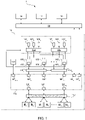
- FIG. 1 is exemplary of an electronic system 1 according to one or more embodiments, such as a system-on-chip (SoC).
- the electronic system 1 may comprise various electronic circuits such as, for instance: a central processing unit 10 (CPU, e.g., a microprocessor), a main system memory 12 (e.g., a system RAM - Random Access Memory), a direct memory access (DMA) controller 14, and a hardware accelerator device 16.
- the hardware accelerator device 16 may be designed to support execution of (basic) arithmetic functions.
- the electronic circuits in the electronic system 1 may be connected by means of a system interconnect network 18, e.g., a SoC interconnect.
- the hardware accelerator device 16 may further comprise a local control unit 161, a local interconnect network 162, a local data memory controller 163, a local ROM controller 164 coupled to a set of local read-only memories, optionally a number P of local read-only memories 165 0 , 165 1 , ..., 165 P-1 (also collectively designated with reference numeral 165 in the present description), and a local configuration memory controller 166 coupled to a set of local configurable coefficient memories, optionally a number P of local configurable coefficient memories 167 0 , 167 1 , ..., 167 P-1 (also collectively designated with reference numeral 167 in the present description).
- the memories 167 may comprise volatile memories (e.g., RAM memories) and/or non-volatile memories (e.g., PCM memories).
- Different embodiments may comprise a different number P of processing elements 160 and/or a different number Q of local data memory banks M.
- P may be equal to 8 and Q may be equal to 16.
- the processing elements 160 may support (e.g., based on a proper static configuration) different processing functions (e.g., floating point single precision 32 bits, fixed-point/integer 32 bits, or 16 or 8 bits with parallel computation or vectored mode).
- different processing functions e.g., floating point single precision 32 bits, fixed-point/integer 32 bits, or 16 or 8 bits with parallel computation or vectored mode.
- the processing elements 160 may comprise respective internal direct memory access (DMA) controllers 168 0 , 168 1 , ..., 168 P-1 (also collectively designated with reference numeral 168 in the present description).
- the processing elements 160 may be configured to retrieve input data from the local data memory banks M and/or from the main system memory 12 through the respective direct memory access controllers 168.
- the processing elements 160 may thus process the retrieved input data to generate output data.
- the processing elements 160 may be configured to store the processed output data in the local data memory banks M and/or in the main system memory 12 via the respective direct memory access controllers 168.
- processing elements 160 may be configured to retrieve input data from the local read-only memories 165 and/or from the local configurable coefficient memories 167 to perform such elaboration.
- the local data memory banks M may be provided with buffering (e.g., double buffering) which may facilitate recovering the memory upload time (write operation) and/or download time (read operation).
- each local data memory bank may be duplicated, so that data can be read (e.g., for being processed) from one of the two memory banks and (new) data can be stored (e.g., for being processed later) in the other memory bank at the same time.
- moving data may not negatively affect computation performances, as it may be masked.
- a double buffering scheme of the local data memory banks M may be advantageous in combination with data processing in streaming mode or back to back (e.g., as applicable to a FFT N-point processor that is configured to elaborate continuous sequences of N data inputs).
- the local control unit 161 may comprise a register file including information for setting up the configuration of the processing elements 160. For instance, the local control unit 161 may set up the processing elements 160 to perform a specific algorithm as directed by a host application running on the central processing unit 10. In one or more embodiments, the local control unit 161 may thus configure (e.g., dynamically) each of the processing elements 160 for computing a specific (basic) function, and may configure each of the respective internal direct memory access controllers 168 with a specific memory access scheme and loop cycle.
- the local interconnect network 162 may comprise a low complexity interconnect system, e.g., based on a bus network of a known type such as an AXI4-based interconnect.
- the data parallelism of the local interconnect network 162 may be on 64 bits and the address width may be 32 bits.
- the local interconnect network 162 may be configured to connect the processing elements 160 to the local data memory banks M and/or to the main system memory 12. Additionally, the local interconnect network 162 may be configured to connect the local control unit 161 and the local configuration memory controller 166 to the system interconnect network 18.
- the interconnect network 162 may comprise:
- the interconnect network 162 may be fixed (i.e., not reconfigurable).
- the interconnect network 162 may implement the following connections:
- the interconnect network 162 may further implement the following connections: each of the P master ports MP 0 , MP 1 , ..., MP P-1 may be connected to the system slave port SP P coupled to the system interconnect network 18. In this way, connectivity may be provided between any processing element 160 and the SoC via the system interconnect network 18.
- the interconnect network 162 may further implement the following connection: the system master port MP P coupled to the system interconnect network 18 may be connected to at least one of the slave ports SP 0 , SP 1 , ..., SP P-1 (here, the first slave port SP 0 in the set of P slave ports SP 0 , SP 1 , ..., SP P-1 ). In this way, connection may be provided between the master port MPp and (any) slave.
- connection of the master port MP P may be extended to a plurality of (e.g., all) the slave ports SP 0 , SP 1 , ..., SP P-1 .
- Connection of the master port MP P to at least one of the slave ports SP 0 , SP 1 , ..., SP P-1 may be used (only) to load the input data to be processed into the local data memory banks M 0 , ..., M Q-1 , insofar as all memory banks may be accessed via a single slave port.
- Loading input data can be done using only one slave port, while processing said data by means of parallel computation may take advantage of using a plurality (e.g., all) of the slave ports SP 0 , SP 1 , .., SP P-1 .
- the local data memory controller 163 may be configured to arbitrate access (e.g., by the processing elements 160) to the local data memory banks M. For instance, the local data memory controller 163 may use memory access schemes selectable as a function of a signal received from the local control unit 161 (e.g., for computation of a specific algorithm).
- the local data memory controller 163 may translate input read/write transaction bursts (e.g., AXI bursts) generated by the read/write direct memory access controllers 168 into a sequence of read/write memory accesses, according to a specified burst type, burst length and memory access scheme.
- input read/write transaction bursts e.g., AXI bursts
- the local read-only memories 165 accessible by the processing elements 160 via the local ROM controller 164 may be configured to store numeric factors and/or fixed coefficients for implementation of specific algorithms or operations (for instance, twiddle factors for FFT computation or other complex coefficients).
- the local ROM controller 164 may implement specific address schemes.
- the local configurable coefficient memories 167 accessible by the processing elements 160 via the local configuration memory controller 166 may be configured to store application-dependent numeric factors and/or coefficients which can be configured by software (for instance, coefficients for implementing a FIR filter or a beamforming operation, weights of a neural network, etc.).
- the local configuration memory controller 166 may implement specific address schemes.
- the local read-only memories 165 and/or the local configurable coefficient memories 167 may advantageously be split into a number P of banks equal to the number of processing elements 160 comprised in the hardware accelerator device 16. This may facilitate avoiding conflicts during parallel computations.
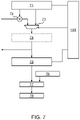
- Figure 2 is a circuit block diagram exemplary of a processing element 160 and related connections to the local ROM controller 164, the local configuration memory controller 166, and the local data memory banks M (with the dotted lines schematically indicating a reconfigurable connection between the processing element 160 and the local data memory banks M via the local interconnect network 162 and the local data memory controller 163).
- a processing element 160 as exemplified in Figure 2 may be configured to receive:
- a processing element 160 may comprise a number of read direct memory access 200 equal to the number of input signals P, Q.
- the processing element 160 may comprise a computing circuit 20 configurable (possibly at runtime) to process the input values P, Q and the input coefficients W0, W1, W2, W3, W4 to produce a first output signal X0 (e.g., a digital signal indicative of a binary value to be stored in a local data memory bank M via a respective write direct memory access 204 0 and buffer register 206 0 such as a FIFO register) and a second output signal X1 (e.g., a digital signal indicative of a binary value to be stored in a local data memory bank M via a respective write direct memory access 204 1 and buffer register 206 1 such as a FIFO register).
- a first output signal X0 e.g., a digital signal indicative of a binary value to be stored in a local data memory bank M via a respective write direct memory access 204 0 and buffer register 206 0 such as a FIFO register
- a second output signal X1 e.g., a
- a processing element 160 may comprise a number of write direct memory access 204 equal to the number of output signals X0, X1.
- programming of the read and/or write direct memory access 200, 204 may be performed via an interface (e.g., an AMBA interface), which may allow to access internal control registers located in the local control unit 161.
- an interface e.g., an AMBA interface
- a processing element 160 may comprise a ROM address generator circuit 208 coupled to the local ROM controller 164 and a memory address generator circuit 210 coupled to the local configuration memory controller 166 to manage data retrieval therefrom.
- a computing circuit 20 may comprise a set of (e.g., highly parallelized) processing resources including, for instance, four complex/real multiplier circuits, two complex addersubtractor circuits, two accumulator circuits, and two activation non-linear function circuits, reconfigurably couplable (e.g., by means of multiplexers) to form different datapaths, with different datapaths corresponding to different mathematical operations.
- processing resources including, for instance, four complex/real multiplier circuits, two complex addersubtractor circuits, two accumulator circuits, and two activation non-linear function circuits, reconfigurably couplable (e.g., by means of multiplexers) to form different datapaths, with different datapaths corresponding to different mathematical operations.
- each lockstep unit 169 may be configured to couple a pair of processing elements 160 to the interconnect network 162.
- a first lockstep unit 169o may be coupled to the DMA controllers 168o and 168 1 of a first processing element 160o and a second processing element 160 1
- a last lockstep unit 169 R-1 may be coupled to the DMA controllers 168 P-1 and 168 P-2 of a last processing element 160 P-1 and a second-to-last processing element 160 P-2 .
- Each lockstep unit 169 may be selectively configured (e.g., by setting a register of the local control unit 161) to pass data between the respective processing elements and the interconnect network so that the processing elements in the respective pair may operate according to two different operation modes:
- a "functional" computation path and a “shadow” computation path may be dynamically configurable for a specific scheme/algorithm, for each pair of processing elements 160 in the hardware accelerator device 16, when high functional safety is demanded.
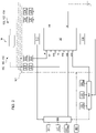
- Figure 3 is a circuit block diagram exemplary of a pair of processing elements 160o, 160 1 coupled to the interconnect network 162 by means of a read lockstep unit 169 0,r and a write lockstep unit 169 0,w .
- the read and write portions of the lockstep unit 169 0 are illustrated as separate circuit blocks for the sake of clarity only, and that in one or more embodiments the read and write portions of a lockstep unit 169 may be implemented in a single circuit.
- a hardware accelerator 16 may thus comprise:
- the functional path (exemplified by the solid lines in Figure 3 ) is related to the main one where the interconnect accesses are performed, while the shadow path (exemplified by the dashed lines in Figure 3 ) is related to the redundant one, where the interconnect accesses are gated in lockstep mode.
- the read lockstep unit 169 0,r may provide a functional read address channel RA f between the interconnect network 162 and the first processing element 160 0 and a shadow read address channel RA s between the interconnect network 162 and the second processing element 160 1 (Read Burst Req/Addr/Ack).
- the read lockstep unit 169 0,r may also provide a functional read response channel RR f between the interconnect network 162 and the first processing element 160o and a shadow read response channel RR s between the interconnect network 162 and the second processing element 160 1 (Read Data).
- the write lockstep unit 169 0,w may provide a functional write address channel WA f between the interconnect network 162 and the first processing element 160 0 and a shadow write address channel WA s between the interconnect network 162 and the second processing element 160 1 (Write Burst Req/Addr/Ack).
- the write lockstep unit 169 0,w may also provide a functional write data channel WD f between the interconnect network 162 and the first processing element 160 0 and a shadow write data channel WD s between the interconnect network 162 and the second processing element 160 1 (Write Data).
- the write lockstep unit 169 0,w may also provide a functional write response channel WR f between the interconnect network 162 and the first processing element 160 0 and a shadow write response channel WR s between the interconnect network 162 and the second processing element 160 1 (Write Resp).
- a read lockstep unit 169 0,r may comprise:
- the circular buffer circuit 300 may be configured to buffer, in lockstep mode, the read requests (address channel, control channel) on the functional read address channel RA f .
- the control logic of the circular buffer circuit 300 may be based on a simple handshake mechanism, request and acknowledge, which allows supporting most of the communication protocols, such as the AXI protocol.
- a new read request (address channel, control channel) can be buffered to be compared later (only) when an entry is still available, otherwise the acknowledge signal may be kept low waiting for an entry to become free.
- all buffer entries are shifted by one position. In high speed mode, the circular buffer circuit 300 may not be enabled and no read request is stored inside the buffer.
- the comparator and gating circuit 302 may be configured to compare, in lockstep mode, the read requests (address channel, control channel) between the functional read address channel RA f , stored inside the buffer 300, and the shadow read address channel RA s , and to gate the request on the shadow read address channel RA s to the interconnect 162 which must not be propagated. As a result of the lockstep mode not being active, the comparator and gating circuit 302 may propagate the request on the shadow read address channel RA s to the local interconnect 162, and data comparison may not take place.
- the read requests address channel, control channel
- the read lockstep unit 169 0,r may be configured to signal faults to a fault collection unit (FCU) in case of failures detected by the comparator and gating circuit 302.
- FCU fault collection unit
- a write lockstep unit 169 0,w may comprise:
- the first circular buffer circuit 312 may be configured to buffer, in lockstep mode, the write requests (address channel, control channel) on the functional write address channel WA f .
- the control logic of the first circular buffer circuit 312 may be based on a simple handshake mechanism, request and acknowledge, which allows supporting most of the communication protocols, such as the AXI protocol.
- a new write request (address channel, control channel) can be buffered to be compared later (only) when an entry is still available, otherwise the acknowledge signal may be kept low waiting for an entry to become free.
- An entry becomes free (only) as a result of a write request arriving from the processing element 160 1 and the data comparison may take place in the comparator circuit 316 between the write request from 160 1 and the first entry of the buffer 312.
- all buffer entries are shifted by one position.
- the first circular buffer circuit 312 may not be enabled, so that write requests are not stored inside the buffer 312 and can be directly propagated to the local interconnect 162.
- the first comparator and gating circuit 316 may be configured to compare, in lockstep mode, the write requests (address channel, control channel) between the functional write address channel WA f , stored inside the buffer 312, and the shadow write address channel WA s , and to gate the request on the shadow write address channel WA s to the interconnect 162 which must not be propagated. As a result of the lockstep mode not being active, the first comparator and gating circuit 316 may propagate the request on the shadow write address channel WA s to the local interconnect 162, and data comparison may not take place.
- the second circular buffer circuit 314 may be configured to buffer, in lockstep mode, the write requests (data channel) on the functional write data channel WD f .
- the control logic of the second circular buffer circuit 314 may be based on a simple handshake mechanism, request and acknowledge, which allows supporting most of the communication protocols, such as the AXI protocol.
- a new write request (data channel) can be buffered to be compared later (only) when an entry is still available, otherwise the acknowledge signal may be kept low waiting for an entry to become free.
- all buffer entries are shifted by one position.
- the second circular buffer circuit 314 may not be enabled so that write requests are not stored inside the buffer 314 and can be directly propagated to the local interconnect 162.
- the second comparator and gating circuit 318 may be configured to compare, in lockstep mode, the write requests (data channel) between the functional write data channel WD f , stored inside the buffer 314, and the shadow write data channel WD s , and to gate the request on the shadow write data channel WD s to the interconnect 162 which must not be propagated. As a result of the lockstep mode not being active, the second comparator and gating circuit 318 may propagate the request on the shadow write data channel WD s to the local interconnect 162, and data comparison may not take place.
- the write lockstep unit 169 0,w may be configured to signal faults to a fault collection unit in case of failures detected by the comparator and gating circuits 316 and/or 318. Additionally or alternatively, the comparator and gating circuits 316 and/or 318 may be configured to gate the write accesses on the functional paths WA f and WD f in order to avoid corrupting the memory content in case of a detected failure.
- the functional read accesses may be immediately propagated to the interconnect network 162 without waiting for a comparison to take place in the comparator circuit 302, while the functional write accesses may be propagated to the interconnect network 162 only after a comparison has taken place in the comparator circuits 316 and/or 318, insofar as an erroneous write access may corrupt the data stored in the memory.
- each pair of processing elements 160 can be programmed to operate according to the pseudo-lockstep mode by setting a respective configuration bit in the configuration registers of the control unit 161, when the hardware accelerator device 16 is used for safety-relevant applications. For instance, if such configuration bit has a first value (e.g., it is equal to 1), the read/write comparator circuits 302, 316, 318 may perform a comparison on the DMA read/write output channels. In response to a mismatch being detected, the corresponding write request may not be propagated, the flow may be stalled and an error may be reported to a (e.g., external) logic fault collection unit (LFCU) of the system-on-chip 1. Alternatively, if such configuration bit has a second value (e.g., it is equal to 0), the requests on the bus may be simply propagated to the memory controller 163.
- LFCU logic fault collection unit
- a “functional" processing element 160o and a “shadow” processing element 160 1 when two processing elements in a pair (i.e., a "functional" processing element 160o and a “shadow” processing element 160 1 ) operate in pseudo-lockstep mode, their operation may be time-shifted (e.g., out of phase). For instance, such a time shift may be equal to a certain number of clock cycles, optionally two clock cycles. This may be obtained, for instance, by means of a hardware architecture as exemplified in Figure 4 .
- the phase shift mechanism may be the same for all internal DMA controllers, e.g., both read DMA controllers and write DMA controllers.
- Such a time shift may facilitate reaching a good coverage against common cause failures. For instance, a fault due to electromagnetic interference (EMI) may result in a failure equal for both the functional path and the shadow path, which would not be detectable by the lockstep unit without a time shift.
- EMI electromagnetic interference
- the DMA controller 168o (read and/or write) of a processing element 160 0 configured as a functional processing element of a pair may receive a start signal START 0 from the control unit 161.
- a delay generating circuit block 400 may receive the start signal START 0 and generate the delayed replica START 0 '.
- a selection circuit 402 e.g., a multiplexer or a gating circuit
- the read/write lockstep units 169 can be configured as basic safety mechanism (without the lockstep comparators, i.e., providing two independent data paths) to protect (only) the data delivery (end to end) to/from the local memories M via the local interconnect 162.
- the hardware accelerator device 16 may support concurrent execution of plural algorithms.
- the corresponding pairs of processing elements can be configured to operate in pseudo-lockstep mode or in high speed mode according to the safety requirements of the specific algorithm.
- a subset of pairs of processing elements may operate in pseudo-lockstep mode while another subset of pairs of processing elements may operate in high speed mode.
- the pseudo-lockstep mode or the high speed mode can be part of the configuration of the hardware accelerator device 16 and may be selectable on algorithm basis.
- a similar safety mechanism may be implemented in the data paths between the processing elements 160 and the configurable coefficient memories 167.
- FIG. 5 is a circuit block diagram exemplary of implementation details of the configurable coefficient memories 167.
- each processing element 160 may comprise a respective memory address generator circuit 210 coupled to the memory controller 166, to which the configurable coefficient memories 167 are coupled.
- the same read lockstep unit 169 r illustrated in Figure 3 may be coupled to the memory address generator circuit 210 to compare the read requests in the coefficient memories 167 between a functional path and a shadow path.
- the same start signal START 0 used for the DMA controllers 168 may be used for the memory address generator circuit 210.
- a similar safety mechanism may be implemented in the data paths between the processing elements 160 and the read-only memories 165.
- each processing element 160 may comprise a respective ROM address generator circuit 208 coupled to a ROM controller 164, to which the read-only memories 165 are coupled.
- the same read lockstep unit 169 r illustrated in Figure 3 may be coupled to the ROM address generator circuit 208 to compare the read requests in the read-only memories 165 between a functional path and a shadow path.
- the same start signal START 0 used for the DMA controllers 168 may be used for the ROM address generator circuit 208.
- a hardware accelerator device 16 may comply with the requirements of the ISO 26262 safety standard by protecting (all) the addresses and the stored data (in the RAM memories and/or in the ROM memories) by means of protection codes such as Double Error Detection (DED), Single Error Correction and Double Error Detection (SECDED), and/or PARITY code.
- DED Double Error Detection
- SECDED Single Error Correction and Double Error Detection
- PARITY code such as Double Error Detection (DED), Single Error Correction and Double Error Detection (SECDED), and/or PARITY code.
- control signals of the local interconnect 162 may be protected by means of a DED or PARITY code. Additionally, PARITY bits may be used for protecting local interconnect handshake bits.
- the read/write DMA controllers 168, the local data memory controller 163, the configurable memory controller 166 and/or the ROM memory controller 164 may thus implement new functionalities in order to provide improved functional safety.
- the protection scheme may be statically configurable according to the requirements of the processing system 1.
- the read DMA controllers 200 may be configured to implement one or more of the following functionalities:
- a read DMA controller 200 may comprise:
- the write DMA controllers 204 may be configured to implement one or more of the following functionalities:
- a write DMA controller 204 may comprise:
- the local data memory controller 163 may be configured to implement one or more of the following functionalities:
- the configurable memory address generator circuit 210 may be configured to implement one or more of the following functionalities:
- the configurable memory controller 166 may be configured to implement one or more of the following functionalities:
- the ROM address generator 208 may be configured to implement generation of DED, SECDED or PARITY code on address.
- the ROM controller 164 may be configured to implement one or more of the following functionalities:
- ECC error-correcting code
- Control signals on a target interface may be generated by a logic block (e.g., a FSM, a decoder, etc.) without keeping the source information on the initiator interface (e.g., an internal DMA, an external AXI interface).
- a logic block e.g., a FSM, a decoder, etc.
- one or more embodiments may comprise (even independently from the implementation of a lockstep architecture as previously described) a memory read/write watchdog mechanism to provide an end-to-end (e.g., initiator-memory, such as DMA-memory) safety mechanism on the control path which may facilitate detecting hard and/or soft faults inside the control logic of the memory controllers.
- a memory read/write watchdog mechanism to provide an end-to-end (e.g., initiator-memory, such as DMA-memory) safety mechanism on the control path which may facilitate detecting hard and/or soft faults inside the control logic of the memory controllers.
- a first type of memory read/write watchdog may be configured to count the number and/or type (read, write, bus width) of memory operations executed during computation of an algorithm (e.g., each algorithm) by a specific initiator (e.g., each initiator).
- one or more embodiments may comprise for each target interface (e.g., the local or system memory) a read/write watchdog circuit including a set of concurrent read/write counters per initiator device (e.g., a counter for each internal DMA controller, a counter for each external bus interface, etc.).
- Each read/write watchdog circuit may track all the operations and store the accumulated results in a set of status registers.
- the content of the watchdog status registers may be compared to an expected number of read/write operations, thereby providing a safety mechanism against possible failure of the control path.
- Figure 6A is a circuit block diagram exemplary of such a first type of memory watchdog for use in one or more embodiments.
- a memory watchdog circuit 60A may comprise a read counter circuit 62Ar and a write counter circuit 62Aw.
- the read counter circuit 62Ar may be configured to receive a respective chip select signal CS, a read enable signal REN, and a respective identification signal ID which carries information suitable to identify the initiator (e.g., an initiator ID).
- the read counter circuit 62Ar may be configured to generate an output read count signal RC, e.g., to be propagated to the watchdog status registers in the local control unit 161.
- the write counter circuit 62Aw may be configured to receive a respective chip select signal CS, a write enable signal WEN, and a respective identification signal ID which carries information suitable to identify the initiator (e.g., an initiator ID).
- the write counter circuit 62Aw may be configured to generate an output write count signal WC, e.g., to be propagated to the watchdog status registers in the local control unit 161.
- a local memory read/write watchdog circuit 60A may be configured to:
- the watchdog status may be checked according to different policies. Those policies may be configurable via the control registers of the local control unit.
- a watchdog status check policy may comprise a software check of the watchdog status at the end of the data processing for the configured algorithm.
- a watchdog status check policy may comprise a hardware check (e.g., automatically triggered at the end of the data processing for the configured algorithm) of the expected number of read/write accesses per memory bank and per initiator, optionally with error signaling to a logic fault collection unit in case of failure.
- the input matrices A and B may be pre-loaded in the local memory M by the system DMA controller 14.
- the output matrix C may be stored in the local memory M by the internal DMA controller 168 of the processing element 160.
- the expected number of write operations executed by the system DMA controller is equal to 2 ⁇ (n ⁇ n)
- the expected number of read operations executed by the internal DMA controller is equal to 2 ⁇ (n ⁇ n ⁇ n)
- the expected number of write operations executed by the internal DMA controller is equal to n ⁇ n.
- a second type of memory read/write watchdog may be configured to count the number of outstanding memory operations during computation of an algorithm (e.g., each algorithm) by a specific initiator (e.g., each read or write internal DMA), with such a number increasing when a transaction is issued and decreasing when a response is received. Therefore, a memory read/write watchdog of the second type may not count an absolute value of memory accesses, but a relative one (e.g., by means of a simple up-down counter circuit), which is expected to be equal to zero at the end of the algorithm.
- an algorithm e.g., each algorithm
- a specific initiator e.g., each read or write internal DMA
- Figure 6B is a circuit block diagram exemplary of such a second type of memory watchdog for use in one or more embodiments.
- a memory watchdog circuit 60B may comprise a read up-down counter circuit 62Br and/or a write up-down counter circuit 62Bw configured to count a difference between the number of words requested to be read or written by each initiator and the number of words actually read or written.
- the read up-down counter circuit 62Br may be configured to receive a respective read enable signal REN and/or a read burst length signal RBURSTL to increase the respective counter value, and receive a respective response enable signal RRESP_EN to decrease the respective counter value. Therefore, in case the initiator interface is a read interface (e.g., the local read DMAs interfaces), the read request and the burst length signals can be used for the increment operation, while the response enable signal (which is used to detect a valid read data) can be used to decrement the up-down counter value. In this exemplary case, all the signals used by the watchdog circuit come from the same initiator interface.
- the write up-down counter circuit 62Bw may be configured to receive a respective write enable signal WEN and/or a write burst length signal WBURSTL to increase the respective counter value, and receive a respective write enable signal W_EN and/or and a respective identification signal INIT_ID which carries information suitable to identify the initiator (e.g., an initiator ID) to decrease the respective counter value.
- the write request and burst length signals can be used to increment the number of words requested to be written, while the write enable signals (which are used to detect a valid data) and the initiator IDs at the target interface (e.g., memory controller output) can be used to decrement the number of words.
- an initiator interface ID can be propagated from each source to the target (e.g., using the AXI user signals) for protecting the write transactions inside the hardware accelerator device.
- an external host controller may read the status of the instantiated watchdogs (e.g., one for each initiator) and verify whether the final count values are equal to zero.
- a mismatch between the number of requests and the number of data actually read/written can be attributed to a fault (e.g., a single point fault, SPF) inside the controllers.
- a fault e.g., a single point fault, SPF
- the watchdog status may be checked according to different policies. Those policies may be configurable via the control registers of the local control unit.
- a watchdog status check policy may comprise a software check of the watchdog status at the end of the data processing for the configured algorithm (when zero outstanding transactions are expected).
- a watchdog status check policy may comprise a hardware check (e.g., automatically triggered at the end of the data processing for the configured algorithm) of the expected number of outstanding transactions per memory bank and per initiator, optionally with error signaling to a logic fault collection unit in case of failure.
- a watchdog status check policy may comprise a hardware or software runtime monitoring, by an interrupt asserted on a configurable threshold, as performance metric (latency, peak/average of outstanding transactions).
- a watchdog mechanism as exemplified in Figure 6B , which relies on counting the numbers of outstanding transactions in the place of a total number of transactions effected, may provide one or more of the following advantages:
- providing a memory read/write watchdog circuit as exemplified in Figure 6A or Figure 6B may contribute to the overall safety goal (local memory banks M, configuration memory 167 and read-only memory 165) while avoiding the duplication of the internal memory controllers and reaching a satisfactory coverage of single point faults (SPFs) inside such blocks.
- SPFs single point faults
- the safety monitors are usually protected against latent faults by their duplication (e.g., in the case of standard cores) or by application of a Logic Built In Self Testing (LBIST) procedure applied to the full/partial device.
- duplication e.g., in the case of standard cores
- LBIST Logic Built In Self Testing
- one or more embodiments may comprise (even independently from the implementation of a lockstep architecture or a memory watchdog mechanism as previously described) a dedicated hardware Built In Self Test (BIST) for the safety monitors.
- BIST Built In Self Test
- such a dedicated hardware BIST may also reduce the unavailability of the device functions, insofar as conventional devices may not be available during execution of LBIST and during a next partial or full reset.
- a dedicated hardware BIST may provide one or more of the following features:
- the BIST may be applied to all safety monitors implemented to support the end-to-end protection schemes, the lock-step comparators, the memory watchdog, and others.
- Figure 7 is a circuit block diagram exemplary of a hardware safety monitor BIST according to one or more embodiments.
- a hardware BIST as exemplified in Figure 7 may comprise:
- the functionality of the hardware accelerator device may be unavailable at run time during execution of the safety monitors BIST.
- a reset of the hardware accelerator device may be required following the execution of the safety monitors BIST.
- the local control unit 161 may represent a source of failure for the hardware accelerator device 16, one or more embodiments may rely on one or more of the following safety mechanisms:
- the interface 78 may comprise a (simple) two-signal level registered interface.
- a first signal e.g., EDPA_cf
- a second signal e.g., EDPA_ncf
- the interface 78 may advantageously signal externally the internally detected errors in order to let the system 1 (e.g., a System-on-Chip) to reach, within an acceptable time interval (Fault Tolerant Time Interval), the safe states required by the safety goals.
- the electronic system 1 may be implemented as an integrated circuit in a single silicon chip or die (e.g., as a system-on-chip).
- the electronic system 1 may comprise a distributed system comprising a plurality of integrated circuits interconnected together, e.g., by means of a printed circuit board (PCB).
- PCB printed circuit board
- one or more embodiments as exemplified herein may provide a hardware accelerator device 16 which can be selectively configured (e.g., at runtime) to operate at a certain level of functional safety (e.g., at the ASIL-D level), e.g., when computation of a safety relevant algorithm is demanded.
- a certain level of functional safety e.g., at the ASIL-D level
- such computation may be speeded up all the internal computational power is made available.
- the functional safety architecture disclosed herein facilitates providing a memory-based hardware accelerator device, and possibly a SoC that integrates the hardware accelerator device, which supports ASIL-D applications with a reduced area overhead.
- a hardware accelerator device may comprise a set of processing circuits (e.g., 160) arranged in subsets (e.g., in pairs) of processing circuits, a set of data memory banks (e.g., M) coupled to a memory controller (e.g., 163), a control unit (e.g., 161) including configuration registers providing storing space for configuration data of said processing circuits, and an interconnect network (e.g., 162).
- the processing circuits may be configured as a function of said configuration data stored in said control unit to read (e.g., 200, 202) first input data from said data memory banks via the interconnect network and the memory controller, process (e.g., 20) said first input data to produce output data, and write (e.g., 204, 206) said output data into said data memory banks via the interconnect network and the memory controller.
- read e.g., 200, 202
- process e.g., 20
- write e.g., 204, 206
- the hardware accelerator device may comprise a set of configurable lockstep control units (e.g., 169) which interface the processing circuits (for instance, the DMA controllers 168) to the interconnect network, each configurable lockstep control unit (e.g., 169o) in said set of configurable lockstep control units being coupled to a subset of processing circuits (e.g., 160o, 160 1 ) in said set of processing circuits.
- Each configurable lockstep control unit can be selectively activated (e.g., LS EN ) to operate in:
- said configurable lockstep control units can be selectively activated to operate in the first operation mode or in the second operation mode as a function of configuration data stored in said control unit.
- a hardware accelerator device may comprise a clock source configured to generate a clock signal
- the configurable lockstep control units may be configured to delay (e.g., 400, 402) processing of said first input data by said second processing circuit with respect to said first processing circuit, optionally by a time period of two clock cycles of said clock signal, in response to the configurable lockstep control units operating in said first operation mode.
- a hardware accelerator device may comprise at least one read-only memory (e.g., 165) coupled to a ROM controller (e.g., 164).
- the processing circuits may be configured to read second input data from said at least one read-only memory via the ROM controller, and process said second input data to produce said output data.
- the lockstep control unit may compare data read requests issued towards said ROM controller by the first processing circuit and the second processing circuit in the respective subset of processing circuits to detect a fault.
- the lockstep control unit may propagate towards said ROM controller said data read requests issued by the first processing circuit and the second processing circuit in the respective subset of processing circuits.
- a hardware accelerator device may comprise at least one local configurable memory (e.g., 167) coupled to a configuration memory controller (e.g., 166).
- the processing circuits may be configured to read third input data from said at least one local configurable memory via the configuration memory controller, and process said third input data to produce said output data.
- the lockstep control unit may compare data read requests issued towards said configuration memory controller by the first processing circuit and the second processing circuit in the respective subset of processing circuits to detect a fault.
- the lockstep control unit may propagate towards said configuration memory controller said data read requests issued by the first processing circuit and the second processing circuit in the respective subset of processing circuits.
- the interconnect network may comprise at least one control channel configured to exchange control messages.
- the processing circuits and/or the memory controller may be configured to include a double error detection (DED) code or a parity code in said control messages.
- DED double error detection
- the interconnect network may comprise at least one address channel configured to exchange address messages and at least one data channel configured to exchange data messages.
- the processing circuits and/or the memory controller may be configured to include a protection code in said address messages and in said data messages.
- the protection code may comprise one of a double error detection (DED) code, a parity code or a single error correction double error detection (SECDED) code.
- the ROM controller may comprise at least one address channel configured to exchange address messages and at least one data channel configured to exchange data messages.
- the processing circuits and/or the ROM controller may be configured to include a protection code in said address messages and in said data messages.
- the protection code may comprise one of a double error detection (DED) code, a parity code or a single error correction double error detection (SECDED) code.
- the configuration memory controller may comprise at least one address channel configured to exchange address messages and at least one data channel configured to exchange data messages.
- the processing circuits and/or the configuration memory controller may be configured to include a protection code in said address messages and in said data messages.
- the protection code may comprise one of a double error detection (DED) code, a parity code or a single error correction double error detection (SECDED) code.
- the hardware accelerator device may comprise an end-to-end mechanism configured to propagate said protection code from said processing circuits to said memory units (e.g., any of the data memory banks M, the read-only memories 165 and/or the local configurable memories 167, depending on the case) and/or from said memory units to said processing circuits via the lockstep control units and the interconnect network as a result of the respective lockstep control unit operating in the first operation mode.
- the end-to-end mechanism may be configured to propagate the protection code between the processing circuits and the memory units as a result of the respective lockstep control unit operating in the second operation mode.
- a hardware accelerator device may comprise a first memory watchdog circuit coupled to said data memory banks, wherein the first memory watchdog circuit (e.g., 60A) is configured to count a first number of memory transaction requests received at said data memory banks, and the hardware accelerator device is configured to compare said first counted number of memory transactions to a first expected number of memory transactions to detect a fault.
- the first expected number of memory transactions may comprise a number of memory transactions for execution of a complete algorithm, or a number of memory transactions for execution of a computation cycle of the algorithm.
- the first memory watchdog circuit (e.g., 60B) may be configured to count a first number of outstanding memory transaction requests received at said data memory banks, and the hardware accelerator device may be configured to check whether said first counted number of outstanding memory transactions is equal to zero to detect a fault.
- the first memory watchdog circuit may comprise a respective counter for each memory transaction initiator.
- the first memory watchdog circuit may be configured to store said first counted number(s) of memory transactions in a status register of the control unit.
- a hardware accelerator device may comprise a second memory watchdog circuit coupled to said at least one read-only memory, wherein the second memory watchdog circuit is configured to count a second number of memory transaction requests received at said at least one read-only memory, and the hardware accelerator device may be configured to compare said second counted number of memory transactions to a second expected number of memory transactions to detect a fault.
- the second expected number of memory transactions may comprise a number of memory transactions for execution of a complete algorithm, or a number of memory transactions for execution of a computation cycle of the algorithm.
- the second memory watchdog circuit may be configured to count a second number of outstanding memory transaction requests received at said at least one read-only memory, and the hardware accelerator device may be configured to check whether said second counted number of outstanding memory transactions is equal to zero to detect a fault.
- the second memory watchdog circuit may comprise a respective counter for each memory transaction initiator.
- the second memory watchdog circuit may be configured to store said second counted number(s) of memory transactions in a status register of the control unit.
- a hardware accelerator device may comprise a third memory watchdog circuit coupled to said at least one local configurable memory, wherein the third memory watchdog circuit may be configured to count a third number of memory transaction requests received at said at least one local configurable memory, and the hardware accelerator device may be configured to compare said third counted number of memory transactions to a third expected number of memory transactions to detect a fault.
- the third expected number of memory transactions may comprise a number of memory transactions for execution of a complete algorithm, or a number of memory transactions for execution of a computation cycle of the algorithm.
- the third memory watchdog circuit may be configured to count a third number of outstanding memory transaction requests received at said at least one local configurable memory, and the hardware accelerator device may be configured to check whether said third counted number of outstanding memory transactions is equal to zero to detect a fault.
- the third memory watchdog circuit may comprise a respective counter for each memory transaction initiator.
- the third memory watchdog circuit may be configured to store said third counted number(s) of memory transactions in a status register of the control unit.
- a hardware accelerator device may comprise a built-in self-test pattern generator circuit (e.g., 71) or a fault injector circuit (e.g., 71) configured to inject a test pattern into said lockstep control units to generate respective test output signals, and a comparator circuit (e.g., 77) configured to compare said test output signals to an expected test output signal to detect a fault of said lockstep control units.
- a built-in self-test pattern generator circuit e.g., 71
- a fault injector circuit e.g., 71
- a comparator circuit e.g., 77
- a system may comprise a hardware accelerator device according to one or more embodiments and a fault collection unit, possibly coupled via a system interconnect (e.g., 18).
- the fault collection unit may be sensitive to said faults detected by the lockstep control units (or by any other safety monitor possibly provided in the hardware accelerator device) and may be configured to set the system into a safe operation mode in response to a fault being detected.
- a method of operating a hardware accelerator device or a system may comprise:
Landscapes
- Engineering & Computer Science (AREA)
- Theoretical Computer Science (AREA)
- Quality & Reliability (AREA)
- Physics & Mathematics (AREA)
- General Engineering & Computer Science (AREA)
- General Physics & Mathematics (AREA)
- Logic Circuits (AREA)
- Multi Processors (AREA)
- Hardware Redundancy (AREA)
- Advance Control (AREA)
Applications Claiming Priority (1)
| Application Number | Priority Date | Filing Date | Title |
|---|---|---|---|
| IT202000029759 | 2020-12-03 |
Publications (4)
| Publication Number | Publication Date |
|---|---|
| EP4009174A2 true EP4009174A2 (de) | 2022-06-08 |
| EP4009174A3 EP4009174A3 (de) | 2022-08-03 |
| EP4009174B1 EP4009174B1 (de) | 2025-02-26 |
| EP4009174C0 EP4009174C0 (de) | 2025-02-26 |
Family
ID=74592623
Family Applications (1)
| Application Number | Title | Priority Date | Filing Date |
|---|---|---|---|
| EP21209056.7A Active EP4009174B1 (de) | 2020-12-03 | 2021-11-18 | Hardware-beschleunigervorrichtung, zugehöriges system und verfahren zum betrieb |
Country Status (2)
| Country | Link |
|---|---|
| US (1) | US11742049B2 (de) |
| EP (1) | EP4009174B1 (de) |
Families Citing this family (5)
| Publication number | Priority date | Publication date | Assignee | Title |
|---|---|---|---|---|
| US11217323B1 (en) | 2020-09-02 | 2022-01-04 | Stmicroelectronics International N.V. | Circuit and method for capturing and transporting data errors |
| US11698833B1 (en) * | 2022-01-03 | 2023-07-11 | Stmicroelectronics International N.V. | Programmable signal aggregator |
| US12360890B2 (en) | 2022-11-10 | 2025-07-15 | SanDisk Technologies, Inc. | Zone-based garbage collection in ZNS SSDs |
| IT202400000057A1 (it) | 2024-01-04 | 2025-07-04 | St Microelectronics Int Nv | Sistema di elaborazione e relativo procedimento |
| US12461880B2 (en) * | 2024-02-19 | 2025-11-04 | Nvidia Corporation | Test data transfer in multi-die systems |
Family Cites Families (9)
| Publication number | Priority date | Publication date | Assignee | Title |
|---|---|---|---|---|
| US4873630A (en) * | 1985-07-31 | 1989-10-10 | Unisys Corporation | Scientific processor to support a host processor referencing common memory |
| AUPO647997A0 (en) * | 1997-04-30 | 1997-05-22 | Canon Information Systems Research Australia Pty Ltd | Memory controller architecture |
| US6854043B2 (en) | 2002-07-05 | 2005-02-08 | Hewlett-Packard Development Company, L.P. | System and method for multi-modal memory controller system operation |
| US8407429B2 (en) * | 2006-06-21 | 2013-03-26 | Element Cxi, Llc | Multi-context configurable memory controller |
| US8390325B2 (en) * | 2006-06-21 | 2013-03-05 | Element Cxi, Llc | Reconfigurable integrated circuit architecture with on-chip configuration and reconfiguration |
| JP2008181380A (ja) | 2007-01-25 | 2008-08-07 | Toshiba Corp | メモリシステムおよびその制御方法 |
| JP5882800B2 (ja) | 2012-03-16 | 2016-03-09 | Necプラットフォームズ株式会社 | リスト命令の検証機能を有する情報処理装置、リスト命令の検証方法、及びリスト命令の検証のためのプログラム |
| US10761925B2 (en) | 2015-03-24 | 2020-09-01 | Nxp Usa, Inc. | Multi-channel network-on-a-chip |
| KR102750810B1 (ko) | 2019-04-19 | 2025-01-08 | 에스케이하이닉스 주식회사 | 컨트롤러 및 그 동작 방법 |
-
2021
- 2021-11-05 US US17/453,811 patent/US11742049B2/en active Active
- 2021-11-18 EP EP21209056.7A patent/EP4009174B1/de active Active
Also Published As
| Publication number | Publication date |
|---|---|
| EP4009174A3 (de) | 2022-08-03 |
| EP4009174B1 (de) | 2025-02-26 |
| EP4009174C0 (de) | 2025-02-26 |
| US11742049B2 (en) | 2023-08-29 |
| US20220180959A1 (en) | 2022-06-09 |
Similar Documents
| Publication | Publication Date | Title |
|---|---|---|
| EP4009174B1 (de) | Hardware-beschleunigervorrichtung, zugehöriges system und verfahren zum betrieb | |
| US5555250A (en) | Data error detection and correction system | |
| Gaisler | A portable and fault-tolerant microprocessor based on the SPARC v8 architecture | |
| US11996158B2 (en) | Hardware accelerator device, corresponding system and method of operation | |
| US7984357B2 (en) | Implementing minimized latency and maximized reliability when data traverses multiple buses | |
| US11327836B1 (en) | Protection of data on a data path in a memory system | |
| US9632869B1 (en) | Error correction for interconnect circuits | |
| WO2007061703A2 (en) | Ecc coding for high speed implementation | |
| CN108268340A (zh) | 校正存储器中的错误的方法 | |
| Ramos et al. | Efficient protection of the register file in soft-processors implemented on Xilinx FPGAs | |
| US20260080961A1 (en) | Glitch detection | |
| US8739012B2 (en) | Co-hosted cyclical redundancy check calculation | |
| US5339322A (en) | Cache tag parity detect circuit | |
| WO2024198468A1 (zh) | 内存纠错方法、内存条、内存控制器和处理器 | |
| Davis et al. | Achieving low-overhead fault tolerance for parallel accelerators with dynamic partial reconfiguration | |
| US12261691B2 (en) | End-to-end transaction integrity through standard interconnect | |
| CN110955916B (zh) | 一种数据完整性保护方法、系统及相关设备 | |
| EP2752768B1 (de) | Fehlererkennung in einem Schaltkreis-Modul | |
| Doettling et al. | S/390 Parallel Enterprise Server Generation 3: A balanced system and cache structure | |
| US5471487A (en) | Stack read/write counter through checking | |
| Wu et al. | Algorithm level RE-computing with shifted operands-a register transfer level concurrent error detection technique | |
| CN114625577A (zh) | 在处理系统中处理任务 | |
| WO2006107380A2 (en) | System for intergrated data integrity verification and method thereof | |
| CN118394281B (zh) | 数据读取方法、装置和芯片 | |
| US20160110241A1 (en) | Apparatus, system and method for protecting data |
Legal Events
| Date | Code | Title | Description |
|---|---|---|---|
| PUAI | Public reference made under article 153(3) epc to a published international application that has entered the european phase |
Free format text: ORIGINAL CODE: 0009012 |
|
| STAA | Information on the status of an ep patent application or granted ep patent |
Free format text: STATUS: THE APPLICATION HAS BEEN PUBLISHED |
|
| AK | Designated contracting states |
Kind code of ref document: A2 Designated state(s): AL AT BE BG CH CY CZ DE DK EE ES FI FR GB GR HR HU IE IS IT LI LT LU LV MC MK MT NL NO PL PT RO RS SE SI SK SM TR |
|
| PUAL | Search report despatched |
Free format text: ORIGINAL CODE: 0009013 |
|
| AK | Designated contracting states |
Kind code of ref document: A3 Designated state(s): AL AT BE BG CH CY CZ DE DK EE ES FI FR GB GR HR HU IE IS IT LI LT LU LV MC MK MT NL NO PL PT RO RS SE SI SK SM TR |
|
| RIC1 | Information provided on ipc code assigned before grant |
Ipc: G06F 11/16 20060101AFI20220630BHEP |
|
| STAA | Information on the status of an ep patent application or granted ep patent |
Free format text: STATUS: REQUEST FOR EXAMINATION WAS MADE |
|
| 17P | Request for examination filed |
Effective date: 20230111 |
|
| RBV | Designated contracting states (corrected) |
Designated state(s): AL AT BE BG CH CY CZ DE DK EE ES FI FR GB GR HR HU IE IS IT LI LT LU LV MC MK MT NL NO PL PT RO RS SE SI SK SM TR |
|
| STAA | Information on the status of an ep patent application or granted ep patent |
Free format text: STATUS: EXAMINATION IS IN PROGRESS |
|
| 17Q | First examination report despatched |
Effective date: 20230504 |
|
| GRAP | Despatch of communication of intention to grant a patent |
Free format text: ORIGINAL CODE: EPIDOSNIGR1 |
|
| STAA | Information on the status of an ep patent application or granted ep patent |
Free format text: STATUS: GRANT OF PATENT IS INTENDED |
|
| INTG | Intention to grant announced |
Effective date: 20241105 |
|
| RIN1 | Information on inventor provided before grant (corrected) |
Inventor name: RE FIORENTIN, LORENZO Inventor name: BORGONOVO, GIAMPIERO |
|
| GRAS | Grant fee paid |
Free format text: ORIGINAL CODE: EPIDOSNIGR3 |
|
| GRAA | (expected) grant |
Free format text: ORIGINAL CODE: 0009210 |
|
| STAA | Information on the status of an ep patent application or granted ep patent |
Free format text: STATUS: THE PATENT HAS BEEN GRANTED |
|
| AK | Designated contracting states |
Kind code of ref document: B1 Designated state(s): AL AT BE BG CH CY CZ DE DK EE ES FI FR GB GR HR HU IE IS IT LI LT LU LV MC MK MT NL NO PL PT RO RS SE SI SK SM TR |
|
| REG | Reference to a national code |
Ref country code: GB Ref legal event code: FG4D |
|
| REG | Reference to a national code |
Ref country code: CH Ref legal event code: EP |
|
| REG | Reference to a national code |
Ref country code: DE Ref legal event code: R096 Ref document number: 602021026706 Country of ref document: DE |
|
| REG | Reference to a national code |
Ref country code: IE Ref legal event code: FG4D |
|
| U01 | Request for unitary effect filed |
Effective date: 20250228 |
|
| U07 | Unitary effect registered |
Designated state(s): AT BE BG DE DK EE FI FR IT LT LU LV MT NL PT RO SE SI Effective date: 20250310 |
|
| PG25 | Lapsed in a contracting state [announced via postgrant information from national office to epo] |
Ref country code: RS Free format text: LAPSE BECAUSE OF FAILURE TO SUBMIT A TRANSLATION OF THE DESCRIPTION OR TO PAY THE FEE WITHIN THE PRESCRIBED TIME-LIMIT Effective date: 20250526 |
|
| PG25 | Lapsed in a contracting state [announced via postgrant information from national office to epo] |
Ref country code: PL Free format text: LAPSE BECAUSE OF FAILURE TO SUBMIT A TRANSLATION OF THE DESCRIPTION OR TO PAY THE FEE WITHIN THE PRESCRIBED TIME-LIMIT Effective date: 20250226 |
|
| PG25 | Lapsed in a contracting state [announced via postgrant information from national office to epo] |
Ref country code: ES Free format text: LAPSE BECAUSE OF FAILURE TO SUBMIT A TRANSLATION OF THE DESCRIPTION OR TO PAY THE FEE WITHIN THE PRESCRIBED TIME-LIMIT Effective date: 20250226 |
|
| PG25 | Lapsed in a contracting state [announced via postgrant information from national office to epo] |
Ref country code: NO Free format text: LAPSE BECAUSE OF FAILURE TO SUBMIT A TRANSLATION OF THE DESCRIPTION OR TO PAY THE FEE WITHIN THE PRESCRIBED TIME-LIMIT Effective date: 20250526 Ref country code: IS Free format text: LAPSE BECAUSE OF FAILURE TO SUBMIT A TRANSLATION OF THE DESCRIPTION OR TO PAY THE FEE WITHIN THE PRESCRIBED TIME-LIMIT Effective date: 20250626 |
|
| PG25 | Lapsed in a contracting state [announced via postgrant information from national office to epo] |
Ref country code: HR Free format text: LAPSE BECAUSE OF FAILURE TO SUBMIT A TRANSLATION OF THE DESCRIPTION OR TO PAY THE FEE WITHIN THE PRESCRIBED TIME-LIMIT Effective date: 20250226 |
|
| PG25 | Lapsed in a contracting state [announced via postgrant information from national office to epo] |
Ref country code: GR Free format text: LAPSE BECAUSE OF FAILURE TO SUBMIT A TRANSLATION OF THE DESCRIPTION OR TO PAY THE FEE WITHIN THE PRESCRIBED TIME-LIMIT Effective date: 20250527 |
|
| PG25 | Lapsed in a contracting state [announced via postgrant information from national office to epo] |
Ref country code: SM Free format text: LAPSE BECAUSE OF FAILURE TO SUBMIT A TRANSLATION OF THE DESCRIPTION OR TO PAY THE FEE WITHIN THE PRESCRIBED TIME-LIMIT Effective date: 20250226 |
|
| PG25 | Lapsed in a contracting state [announced via postgrant information from national office to epo] |
Ref country code: CZ Free format text: LAPSE BECAUSE OF FAILURE TO SUBMIT A TRANSLATION OF THE DESCRIPTION OR TO PAY THE FEE WITHIN THE PRESCRIBED TIME-LIMIT Effective date: 20250226 |
|
| PG25 | Lapsed in a contracting state [announced via postgrant information from national office to epo] |
Ref country code: SK Free format text: LAPSE BECAUSE OF FAILURE TO SUBMIT A TRANSLATION OF THE DESCRIPTION OR TO PAY THE FEE WITHIN THE PRESCRIBED TIME-LIMIT Effective date: 20250226 |
|
| U20 | Renewal fee for the european patent with unitary effect paid |
Year of fee payment: 5 Effective date: 20251022 |
|
| PLBE | No opposition filed within time limit |
Free format text: ORIGINAL CODE: 0009261 |
|
| STAA | Information on the status of an ep patent application or granted ep patent |
Free format text: STATUS: NO OPPOSITION FILED WITHIN TIME LIMIT |
|
| 26N | No opposition filed |
Effective date: 20251127 |