EP4009093B1 - Optical lens and camera module - Google Patents
Optical lens and camera module Download PDFInfo
- Publication number
- EP4009093B1 EP4009093B1 EP20849919.4A EP20849919A EP4009093B1 EP 4009093 B1 EP4009093 B1 EP 4009093B1 EP 20849919 A EP20849919 A EP 20849919A EP 4009093 B1 EP4009093 B1 EP 4009093B1
- Authority
- EP
- European Patent Office
- Prior art keywords
- lens
- diaphragm
- lens group
- disposed
- optical
- Prior art date
- Legal status (The legal status is an assumption and is not a legal conclusion. Google has not performed a legal analysis and makes no representation as to the accuracy of the status listed.)
- Active
Links
- 230000003287 optical effect Effects 0.000 title claims description 100
- 238000003384 imaging method Methods 0.000 claims description 36
- 239000000758 substrate Substances 0.000 claims description 19
- 230000008030 elimination Effects 0.000 claims description 14
- 238000003379 elimination reaction Methods 0.000 claims description 14
- 238000005096 rolling process Methods 0.000 description 50
- 239000003292 glue Substances 0.000 description 12
- 230000001788 irregular Effects 0.000 description 4
- 230000013011 mating Effects 0.000 description 4
- 239000000853 adhesive Substances 0.000 description 3
- 230000001070 adhesive effect Effects 0.000 description 3
- 239000011521 glass Substances 0.000 description 3
- 239000000463 material Substances 0.000 description 3
- 239000011347 resin Substances 0.000 description 3
- 229920005989 resin Polymers 0.000 description 3
- 238000009434 installation Methods 0.000 description 2
- 239000007787 solid Substances 0.000 description 2
- 241000735235 Ligustrum vulgare Species 0.000 description 1
- 230000008859 change Effects 0.000 description 1
- 238000004891 communication Methods 0.000 description 1
- 230000000295 complement effect Effects 0.000 description 1
- -1 dropping Substances 0.000 description 1
- 239000000428 dust Substances 0.000 description 1
- 239000002360 explosive Substances 0.000 description 1
- 230000014509 gene expression Effects 0.000 description 1
- 210000003128 head Anatomy 0.000 description 1
- 229910044991 metal oxide Inorganic materials 0.000 description 1
- 150000004706 metal oxides Chemical class 0.000 description 1
- 238000000034 method Methods 0.000 description 1
- 238000012986 modification Methods 0.000 description 1
- 230000004048 modification Effects 0.000 description 1
- 238000005457 optimization Methods 0.000 description 1
- 239000004033 plastic Substances 0.000 description 1
- 230000008569 process Effects 0.000 description 1
- 210000001747 pupil Anatomy 0.000 description 1
- 239000004065 semiconductor Substances 0.000 description 1
- 239000012780 transparent material Substances 0.000 description 1
- XLYOFNOQVPJJNP-UHFFFAOYSA-N water Substances O XLYOFNOQVPJJNP-UHFFFAOYSA-N 0.000 description 1
Images


Classifications
-
- G—PHYSICS
- G02—OPTICS
- G02B—OPTICAL ELEMENTS, SYSTEMS OR APPARATUS
- G02B13/00—Optical objectives specially designed for the purposes specified below
- G02B13/001—Miniaturised objectives for electronic devices, e.g. portable telephones, webcams, PDAs, small digital cameras
- G02B13/0055—Miniaturised objectives for electronic devices, e.g. portable telephones, webcams, PDAs, small digital cameras employing a special optical element
- G02B13/0065—Miniaturised objectives for electronic devices, e.g. portable telephones, webcams, PDAs, small digital cameras employing a special optical element having a beam-folding prism or mirror
-
- G—PHYSICS
- G02—OPTICS
- G02B—OPTICAL ELEMENTS, SYSTEMS OR APPARATUS
- G02B13/00—Optical objectives specially designed for the purposes specified below
- G02B13/001—Miniaturised objectives for electronic devices, e.g. portable telephones, webcams, PDAs, small digital cameras
- G02B13/0015—Miniaturised objectives for electronic devices, e.g. portable telephones, webcams, PDAs, small digital cameras characterised by the lens design
- G02B13/002—Miniaturised objectives for electronic devices, e.g. portable telephones, webcams, PDAs, small digital cameras characterised by the lens design having at least one aspherical surface
- G02B13/0045—Miniaturised objectives for electronic devices, e.g. portable telephones, webcams, PDAs, small digital cameras characterised by the lens design having at least one aspherical surface having five or more lenses
-
- G—PHYSICS
- G02—OPTICS
- G02B—OPTICAL ELEMENTS, SYSTEMS OR APPARATUS
- G02B15/00—Optical objectives with means for varying the magnification
- G02B15/14—Optical objectives with means for varying the magnification by axial movement of one or more lenses or groups of lenses relative to the image plane for continuously varying the equivalent focal length of the objective
-
- G—PHYSICS
- G02—OPTICS
- G02B—OPTICAL ELEMENTS, SYSTEMS OR APPARATUS
- G02B13/00—Optical objectives specially designed for the purposes specified below
- G02B13/18—Optical objectives specially designed for the purposes specified below with lenses having one or more non-spherical faces, e.g. for reducing geometrical aberration
-
- G—PHYSICS
- G02—OPTICS
- G02B—OPTICAL ELEMENTS, SYSTEMS OR APPARATUS
- G02B15/00—Optical objectives with means for varying the magnification
- G02B15/14—Optical objectives with means for varying the magnification by axial movement of one or more lenses or groups of lenses relative to the image plane for continuously varying the equivalent focal length of the objective
- G02B15/143—Optical objectives with means for varying the magnification by axial movement of one or more lenses or groups of lenses relative to the image plane for continuously varying the equivalent focal length of the objective having three groups only
- G02B15/1435—Optical objectives with means for varying the magnification by axial movement of one or more lenses or groups of lenses relative to the image plane for continuously varying the equivalent focal length of the objective having three groups only the first group being negative
-
- G—PHYSICS
- G02—OPTICS
- G02B—OPTICAL ELEMENTS, SYSTEMS OR APPARATUS
- G02B5/00—Optical elements other than lenses
- G02B5/005—Diaphragms
-
- G—PHYSICS
- G02—OPTICS
- G02B—OPTICAL ELEMENTS, SYSTEMS OR APPARATUS
- G02B5/00—Optical elements other than lenses
- G02B5/02—Diffusing elements; Afocal elements
- G02B5/0205—Diffusing elements; Afocal elements characterised by the diffusing properties
- G02B5/021—Diffusing elements; Afocal elements characterised by the diffusing properties the diffusion taking place at the element's surface, e.g. by means of surface roughening or microprismatic structures
-
- G—PHYSICS
- G02—OPTICS
- G02B—OPTICAL ELEMENTS, SYSTEMS OR APPARATUS
- G02B5/00—Optical elements other than lenses
- G02B5/02—Diffusing elements; Afocal elements
- G02B5/0268—Diffusing elements; Afocal elements characterized by the fabrication or manufacturing method
-
- G—PHYSICS
- G02—OPTICS
- G02B—OPTICAL ELEMENTS, SYSTEMS OR APPARATUS
- G02B5/00—Optical elements other than lenses
- G02B5/02—Diffusing elements; Afocal elements
- G02B5/0273—Diffusing elements; Afocal elements characterized by the use
- G02B5/0278—Diffusing elements; Afocal elements characterized by the use used in transmission
-
- G—PHYSICS
- G02—OPTICS
- G02B—OPTICAL ELEMENTS, SYSTEMS OR APPARATUS
- G02B5/00—Optical elements other than lenses
- G02B5/02—Diffusing elements; Afocal elements
- G02B5/0273—Diffusing elements; Afocal elements characterized by the use
- G02B5/0284—Diffusing elements; Afocal elements characterized by the use used in reflection
-
- G—PHYSICS
- G02—OPTICS
- G02B—OPTICAL ELEMENTS, SYSTEMS OR APPARATUS
- G02B7/00—Mountings, adjusting means, or light-tight connections, for optical elements
- G02B7/02—Mountings, adjusting means, or light-tight connections, for optical elements for lenses
- G02B7/021—Mountings, adjusting means, or light-tight connections, for optical elements for lenses for more than one lens
Definitions
- the present disclosure relates to the field of consuming electronics, and in particular to an optical lens, a camera module, and an image capturing device.
- a lens is typically configured with a single diaphragm. While a physical size of the diaphragm remains unchanged, the diaphragm is moved together with a zoom lens group or a compensation lens group to match various sizes of a pupil aperture at various focal lengths. Since optimization can be performed only to allow various physical sizes of the diaphragm to be similar at various focal lengths, it is unable to ensure the various physical sizes of the diaphragm to be identical at various focal lengths. In this way, stray light or vignetting may be brought to an actual lens.
- an image-sensing apparatus which has a zoom lens system for forming an optical image of an object with variable magnification, which zoom lens system includes a plurality of lens units and achieves zooming by varying distances between the lens units, and an image sensor for converting the optical image formed by the zoom lens system into an electrical signal.
- the zoom lens system has, from the object side, a first lens unit that has a positive optical power, includes a reflective member for turning the optical path, and is kept stationary relative to the image sensor during zooming, a second lens unit that is disposed on the image side of the first lens unit and has a negative optical power, an aperture stop that is disposed on the image side of the second lens unit and is kept stationary relative to the image sensor during zooming, and at least one lens unit that is disposed on the image side of the aperture stop and is moved relative to the image sensor during zooming.
- the present disclosure provides an optical lens, set out as the appended set of claims.
- the optical lens, the camera module and the image capturing device are provided with a first diaphragm and a second diaphragm.
- the second diaphragm, the second lens group and the third lens group are moved relative to the prism, such that, in the long focal length state, the first diaphragm is an aperture diaphragm, and the second diaphragm is a stray light elimination diaphragm.
- the second diaphragm is the aperture diaphragm
- the first diaphragm is the stray light elimination diaphragm. In this way, a risk of the stray light or vignetting may be reduced, and the performance of the optical lens is improved.
- a first feature being “above” or “below” a second feature may be direct contact between the first feature and the second feature, or indirect contact between the first feature and the second feature through an intermediate medium.
- the first feature being “above”, “on” and “on top of” the second feature may indicate the first feature being directly above or diagonally above the second feature, or simply indicate that the first feature is horizontally higher than the second feature.
- the first feature being “below”, “under”, and “at a bottom of” the second feature may indicate the first feature being directly below or diagonally below the second feature, or simply indicate that a horizontal height of the first feature is less than that of the second feature.
- the present disclosure provides an optical lens 10.
- the optical lens 10 successively includes a prism 20, a first lens group 30, a second lens group 40, and a third lens group 50.
- the prism 20 is fixed relative to an imaging surface 70 of the optical lens 10.
- a first diaphragm 36 is disposed between the first lens group 30 and the prism 20.
- a second diaphragm 48 is disposed between the second lens group 40 and the third lens group 50 or between the first lens group 30 and the second lens group 40.
- the prism 20 When the optical lens 10 switches between a short focal length state and a long focal length state, the prism 20 is fixed, the first lens group 30 and the first diaphragm 36 are fixed relative to the prism 20, and the second lens group 40, the third lens group 50, and the second diaphragm 48 move along an optical axis O of the optical lens 10 relative to the prism 20.
- the first diaphragm 36 is an aperture diaphragm
- the second diaphragm 48 is a stray light elimination diaphragm.
- the second diaphragm 48 In the short focal length state, the second diaphragm 48 is an aperture diaphragm, and the first diaphragm 36 is a stray light elimination diaphragm.
- the optical lens 10 is arranged with the first diaphragm 36 and the second diaphragm 48.
- the second diaphragm 48, the second lens group 40, and the third lens group 50 are movable relative to the prism 20, such that, in the long focal length state, the first diaphragm 36 serves as the aperture diaphragm, and the second diaphragm 48 serves as the stray light elimination diaphragm; and in the short focal length state, the second diaphragm 48 serves as the aperture diaphragm, and the first diaphragm 36 serves as the stray light elimination diaphragm.
- a risk of stray light or vignetting of the optical lens 10 is reduced, and the performance of the optical lens 10 is improved.
- the optical lens 10 includes the prism 20, the first lens group 30, the second lens group 40, the third lens group 50, the first diaphragm 36, the second diaphragm 48, a filter 60, and the imaging surface 70.
- the prism 20, the first lens group 30 (the first diaphragm 36 together with the first lens group 30), the second lens group 40 (the second diaphragm 48 together with the second lens group 40), the third lens group 50, the filter 60, and the imaging surface 70 are arranged successively.
- the prism 20 includes a light inlet surface 22, a light outlet surface 24, and a reflective surface 26. External light is injected through the light inlet surface 22 of the prism 20, reflected by the reflective surface 26 of the prism 20, then emitted to out of the prism 20 through the light outlet surface 24, and reaches the first lens group 30.
- the prism 20 is a right-angle prism 20.
- the prism 20 is shown as a right triangle. Two sides at which two short sides of the right triangle of the prism 20 locate are the light inlet surface 22 and the light outlet surface 24, respectively.
- a side at which a long side of the right triangle of the prism 20 locates is the reflective surface 26.
- An angle between the light inlet surface 22 and the reflective surface 26 may be 45 degrees, 30 degrees, 60 degrees, and the like. In the present embodiment, the angle between the light inlet surface 22 and the reflective surface 26 is 45 degrees.
- the external light may be reflected by the reflective surface 26 of the prism 20 to directly reach the first lens group 30 without passing through an inside of the prism 20. In this case, no light reaches the light inlet surface 22 or the light outlet surface 24.
- the surfaces 22 and 24 may not be called "the light inlet surface” and "the light outlet surface”.
- the prism 20, the first lens group 30, the second lens group 40, and the third lens group 50 are co-axial, and an axis shared by these elements is the optical axis O.
- the first lens group 30 is spaced apart from and fixed relative to the light outlet surface 24 of the prism 20. A center of the first lens group 30 locates on the optical axis O.
- the first lens group 30 includes a first lens 32 and a second lens 34.
- the first lens 32 and the second lens 34 are spaced apart and kept fixed relative to each other. A distance between the first lens 32 and the second lens 34 may be determined based on sizes of the two lenses, optical parameters, and the like, which is not limited by the present disclosure.
- the first lens 32 and the second lens 34 are fixed arranged inside the first shell 320 by a transparent lens adhesive (shown in FIG. 5 ).
- a transmission-enhancing film is disposed on at least one of the first lens 32 and the second lens 34, such that intensity of reflected light is reduced, and intensity of transmitted light is increased, allowing the optical lens 10 to image more clearly.
- the transmission-enhancing film may be disposed on an object side of the first lens 32 or an object side of the second lens 34.
- a center of the second lens group 40 locates on the optical axis O.
- the second lens group 40 is movable along the optical axis O of the optical lens 10 relative to the prism 20.
- the second lens group 40 includes a third lens 42, a fourth lens 44, and a fifth lens 46 that are fixedly arranged in sequence.
- the third lens 42, the fourth lens 44, and the fifth lens 46 are spaced apart from each other and are kept fixed relative to each other.
- a distance between the third lens 42 and the fourth lens 44, and a distance between the fourth lens 44 and the fifth lens 46 may be determined based on sizes of the lenses, optical parameters, and the like, which is not limited by the present disclosure.
- the third lens 42, the fourth lens 44 and the fifth lens 46 may be fixedly arranged inside a second shell 420 by a transparent lens adhesive (shown in FIG. 5 ).
- a transmission-enhancing film is disposed on at least one of the third lens 42, the fourth lens 44 and the fifth lens 46, such that intensity of reflected light of the lenses is reduced, and intensity of transmitted light is increased, allowing the optical lens 10 to image more clearly.
- the transmission-enhancing film may be disposed on an object side of the third lens 42, or an object side of the fourth lens 44, or an object side of the fifth lens 46, and so on, which will not be listed one by one hereinafter.
- a center of the third lens group 50 locates on the optical axis O.
- the third lens group 50 is movable along the optical axis O of the optical lens 10 relative to the prism 20.
- the third lens group 50 includes a sixth lens 52 and a seventh lens 54.
- the sixth lens 52 and the seventh lens 54 are spaced apart from and are fixed relative to each other.
- a distance between the sixth lens 52 and the seventh lens 54 may be determined based on sizes of the lenses, optical parameters, and the like, which is not limited by the present disclosure.
- the sixth lens 52 and the seventh lens 54 may be fixedly arranged inside a third shell 520 by a transparent lens adhesive (shown in FIG. 5 ).
- a transmission-enhancing film is disposed on the sixth lens 52 and the seventh lens 54, such that intensity of reflected light of the lenses is reduced, and intensity of transmitted light is increased, allowing the optical lens 10 to image more clearly.
- the transmission-enhancing film may be disposed on an object side of the sixth lens 52, or an object side of the seventh lens 54, and so on, which will not be listed one by one hereinafter. Changing distances of the second lens group 40 and the third lens group 50 relative to the first lens group 30 may allow the optical lens 10 to switch between the long focal length state and the short focal length state.
- Each of the first lens 32, the second lens 34, the third lens 42, the fourth lens 44, the fifth lens 46, the sixth lens 52, and the seventh lens 54 is a non-spheric lens.
- the first lens 32, the second lens 34, the third lens 42, the fourth lens 44, the fifth lens 46, the sixth lens 52, and the seventh lens 54 are made of transparent materials, such as glass, resin, plastic and the like.
- all seven lenses may be made of glass or resin.
- some of the seven lenses may be made of glass, and the rest of the seven lenses may be made of resin.
- the present disclosure does not limit the materials for making the lenses.
- Each of the first diaphragm 36 and the second diaphragm 48 is a diaphragm having a fixed aperture size.
- a physical aperture size of first diaphragm 36 is D1
- a physical aperture size of second diaphragm 48 is D2.
- the first diaphragm 36 is disposed between the first lens group 30 and the prism 20. Disposing the first diaphragm 36 between the first lens group 30 and the prism 20 may refer to the first diaphragm 36 disposed on the first lens group 30; or the first diaphragm 36 disposed on the prism 20; or the first diaphragm 36 disposed at any position in a space between the first lens group 30 and the prism 20.
- the first diaphragm 36 is disposed on the object side of the first lens 32.
- the first diaphragm 36 and the first lens group 30 are fixedly arranged in the first shell 320 by glue, by snapping, and the like, such that the first diaphragm 36 is fixed relative to the first lens group 30 (as shown in FIG. 7 ).
- the first diaphragm 36 may be disposed on the light outlet surface 24 of the prism 20.
- the first diaphragm 36 may be disposed on the object side of the second lens 34.
- the first diaphragm 36 may be disposed in the space between the first lens 32 and the second lens 34. The present disclosure does not limit the position of the first diaphragm 36, as long as the first diaphragm 36 is disposed between the first lens group 30 and the prism 20.
- the second diaphragm 48 does not coincide with the first diaphragm 36.
- the second diaphragm 48 is disposed between the second lens group 40 and the third lens group 50 or between the first lens group 30 and the second lens group 40.
- the second diaphragm 48 is disposed at any position between the second lens 34 and the imaging surface 70, and the second diaphragm 48 may move along with the third lens group 50.
- Disposing the second diaphragm 48 between the second lens group 40 and the third lens group 50 may refer to the second diaphragm 48 being disposed on the second lens group 40; or the second diaphragm 48 being disposed on the third lens group 50; or the second diaphragm 48 being disposed at any position in a space between the second lens group 40 and the third lens group 50.
- Disposing the second diaphragm 48 between the first lens group 30 and the second lens group 40 may refer to the second diaphragm 48 being disposed on the second lens group 40; or the second diaphragm 48 being disposed on the first lens group 30; or the second diaphragm 48 being disposed at any position in a space between the second lens group 40 and the first lens group 30.
- the second diaphragm 48 is disposed between the first lens group 30 and the second lens group 40, and the second diaphragm 48 is disposed on the object side of the third lens 42, such that the second diaphragm 48 moves along with the second lens group 40 (as shown in FIG. 7 , the second diaphragm 48 and the second lens group 40 may be fixed in the second shell 420 by glue, by snapping, and the like.
- the second diaphragm 48 may be fixed relative to the second lens group 40. When the second shell 420 moves, the second diaphragm 48 and the second lens group 40 may move along with the second shell 420).
- the second diaphragm 48 may be disposed in the space between the second lens 34 and the third lens 42, and the second diaphragm 48 is fixed to the second lens group 40 and moves along with the second lens group 40. In some embodiments, the second diaphragm 48 may be disposed in the space between the sixth lens 52 and the seventh lens 54, and the second diaphragm 48 is fixed to the third lens group 50 and moves along with the third lens group 50.
- the second diaphragm 48 may be disposed in the space between the seventh lens 54 and the imaging surface 70, and the second diaphragm 48 is fixed to the third lens group 50 and moves along with the third lens group 50 (when the second diaphragm 48 moves along with the third lens group 50, installation of the second diaphragm 48 and the third lens group 50 may be referred to installation of the second diaphragm 48 and the second lens group 40).
- the present disclosure does not limit the position of the second diaphragm 48, as long as the position of the second diaphragm 48 and the first diaphragm 36 do not coincide with each other, and the second diaphragm 48 is disposed at any position in the space between the second lens 34 and the imaging surface 70.
- the filter 60 is an infrared filter and is disposed between the seventh lens 54 and the imaging surface 70. That is, the filter 60 is disposed in the space between the third lens group 50 and the imaging surface 70.
- the prism 20 When the optical lens 10 switches between the short focal length state (shown in FIG. 2 ) and the long focal length state (shown in FIG. 1 ), the prism 20 is fixed, the first lens group 30 and the first diaphragm 36 are fixed relative to the prism 20, and the second lens group 40, the second diaphragm 48, and the third lens group 50 move along the optical axis O of the optical lens 10 relative to the prism 20 or relative to the first lens group 30.
- the first diaphragm 36 serves as the aperture diaphragm
- the second diaphragm 48 serves as the stray light elimination diaphragm
- the second diaphragm 48 serves as the aperture diaphragm
- the first diaphragm 36 serves as the stray light elimination diaphragm
- the prism 20 When the optical lens 10 is switched from the long focal length state to the short focal length state, the prism 20 is fixed, the first lens group 30 and the first diaphragm 36 are fixed relative to the prism 20, the third lens group 50 moves from the imaging side to the object side along the optical axis O, and the second lens group 40 and the second diaphragm 48 move from the object side to the imaging side along the optical axis O.
- the prism 20 When the optical lens 10 is switched from the short focal length state to the long focal length state, the prism 20 is fixed, the first lens group 30 and the first diaphragm 36 are fixed relative to the prism 20, the third lens group 50 moves from the object side to the imaging side along the optical axis O, and the second lens group 40 and the second diaphragm 48 move from the imaging side to the object side along the optical axis O.
- the physical aperture size of the first diaphragm 36 is D1
- the physical aperture size of the second diaphragm 48 is D2.
- a light beam aperture size at a location where the first diaphragm 36 is disposed is A1
- a light beam aperture size at a location where the second diaphragm 48 is disposed is A2.
- a light beam aperture size at a location where the first diaphragm 36 is disposed is B1
- a light beam aperture size at a location where the second diaphragm 48 is disposed is B2.
- D2 B2, D1>B1
- the field of view is 30.5 degrees.
- the camera module 1000 includes a shell 100, a prism assembly 200, a first lens assembly 300, a second lens assembly 400, and a third lens assembly 500, an optical lens 10, and a light sensitive element 600.
- the prism 20 of the optical lens 10 is mounted in the prism assembly 200
- the first lens group 30 is mounted in the first lens assembly 300
- the second lens group 40 is mounted in the second lens assembly 400
- the third lens group 50 is mounted in the third lens assembly 500.
- the prism assembly 200, the first lens assembly 300, the second lens assembly 400, the third lens assembly 500, the filter 60, and the light sensitive element 600 are successively arranged inside the shell 100.
- the prism assembly 200 and the first lens assembly 300 are spaced apart from each other and fixedly arranged inside the shell 100.
- the second lens assembly 400 and the third lens assembly 500 are slidably arranged inside the shell 100, and are movable relative to the first lens assembly 300.
- the imaging surface 70 of the optical lens 10 is formed on a surface of the light sensitive element 600 facing the third lens assembly 500. In other words, the surface of the light sensitive element 600 facing the third lens assembly 500 serves as the imaging surface 70.
- the light sensitive element 600 is opposite and fixed to the prism assembly 200.
- the light sensitive element 600 is configured to convert a received light signal into an electrical signal.
- the shell 100 includes a substrate 120, a side plate 140 and a cover 160.
- the substrate 120, the side plate 140 and the cover 160 cooperatively defines a receiving space 180.
- the prism assembly 200, the first lens assembly 300, the second lens assembly 400, the third lens assembly 500 and the light sensitive element 600 are received in the receiving space 180.
- a direction parallel to the optical axis O is defined as an x-direction
- a direction perpendicular to the x-direction is defined as a y-direction and a z-direction. Any two of the x-direction, y-direction and z-direction are perpendicular to each other.
- the substrate 120 includes a carrying surface 122 for carrying the side plate 140.
- the substrate 120 may be rectangular, cuboid, cylindrical, or a structure in other shapes, which will not be limited by the present disclosure. In the present embodiment, the substrate 120 is rectangular.
- the side plate 140 includes an inner surface 141, an outer surface 142, an upper surface 143, and a lower surface 144.
- the inner surface 141 is opposite to the outer surface 142.
- the inner surface 141 is received in the receiving space 180.
- the outer surface 142 is exposed out of the receiving space 180.
- the inner surface 141 is connected to both the upper surface 143 and the lower surface 144.
- the outer surface 142 is connected to both the upper surface 143 and the lower surface 144.
- the upper surface 143 is opposite to the lower surface 144.
- the lower surface 144 is attached to the carrying surface 122 of the substrate 120, and the upper surface 143 is opposite to the carrying surface 122 of the substrate 120.
- the side plate 140 further includes a first side plate 145 and a second side plate 146 that are parallel to the x-direction.
- a length direction of the first side plate 145 and a length direction of the second side plate 146 are parallel to the x-direction.
- the first side plate 145 is opposite to the second side plate 146.
- the inner surface 141 of the first side plate 145 and/or the inner surface 141 of the second side plate 146 defines a slide groove 1452 and a mounting slot 1454.
- the inner surface 141 of the first side plate 145 defines the slide groove 1452 and the mounting slot 1454.
- the inner surface 141 of the second side plate 146 defines the slide groove 1452 and the mounting slot 1454.
- each of the inner surface 141 of the first side plate 145 and the inner surface 141 of the second side plate 146 defines the slide groove 1452 and the mounting slot 1454.
- each of the inner surface 141 of the first side plate 145 and the inner surface 141 of the second side plate 146 defines the slide groove 1452 and the mounting slot 1454, and an extending direction of the slide groove 1452 is parallel to the carrying surface 122.
- the slide groove 1452 is communicated to the receiving space 180.
- the extending direction of the slide groove 1452 is also parallel to the x-direction.
- a depth of the slide groove 1452 is less than a thickness of the side plate 140. That is, the slide groove 1452 does not penetrate through the outer surface 142 of the side plate 140. In other embodiments, the slide groove 1452 may penetrate through the outer surface 142 of the side plate 140 to allow the receiving space 180 to be communicated to the outside.
- the number of slide grooves 1452 defined in the inner surface 141 of the first side plate 145 and in the inner surface of the second side plate 146 may be one or more.
- the inner surface 141 of the first side plate 145 defines one slide groove 1452
- the inner surface 141 of the second side plate 146 defines one slide groove 1452
- the inner surface 141 of the first side plate 145 defines two slide grooves 1452
- the inner surface 141 of the second side plate 146 defines two slide grooves 1452
- the inner surface 141 of the first side plate 145 defines one slide groove 1452
- the inner surface 141 of the second side plate 146 defines two slide grooves 1452.
- each of the inner surface 141 of the first side plate 145 and the inner surface 141 of the second side plate 146 defines one slide groove 1452.
- a shape of the slide groove 1452 intercepted by a plane perpendicular to the x-direction may be rectangular, semicircular, or in other shapes, such as other regular shapes or irregular shapes. As shown in FIG. 6 , in the present embodiment, the slide groove 1452 may be intercepted by the plane perpendicular to the x-direction into a D-shape.
- the mounting slot 1454 is communicated to the receiving space 180.
- An end of the mounting slot 1454 extends through the upper surface 143 of the side plate 140, and the other end of the mounting slot 1454 is communicated to the slide groove 1452.
- An extension direction of the mounting slot 1454 may be perpendicular or inclined to the extension direction of the slide groove 1452.
- the extension direction of the mounting slot 1454 is perpendicular to the x-direction.
- the extension direction of the mounting slot 1454 is inclined at a certain angle (not 0 degree, but may be 30 degrees, 60 degrees, 75 degrees, and the like) to the x-direction.
- the extension direction of the mounting slot 1454 is perpendicular to the x-direction.
- the number of mounting slots 1454 defined in the inner surface 141 of the first side plate 145 and in the inner surface 141 of the second side plate 146 may be one or more.
- the inner surface 141 of the first side plate 145 defines one mounting slot 1454
- the inner surface 141 of the second side plate 146 defines one mounting slot 1454.
- the inner surface 141 of the first side plate 145 defines two mounting slots 1454
- the inner surface 141 of the second side plate 146 defines two mounting slots 1454.
- the inner surface 141 of the first side plate 145 defines one mounting slot 1454
- the inner surface 141 of the second side plate 146 defines two mounting slots 1454.
- each of the inner surface 141 of the first side plate 145 and the inner surface 141 of the second side plate 146 defines two mounting slots 1454.
- the cover 160 is disposed on the upper surface 143 of the side plate 140.
- the cover 160 may be mounted to the upper surface 143 of the side plate 140 by snapping, by screwing, by glue, and the like.
- the cover 160 includes a cover body 162 and an abutting portion 164.
- the cover body 162 is attached with the upper surface 143 of the side plate 140.
- the cover body 162 defines a light inlet port 1622.
- a depth direction of the light inlet port 1622 may be perpendicular to the x-direction, such that the entire camera module 1000 may be in a periscopic structure.
- the external light can be directed into the receiving space 180 through the light inlet port 1622.
- the abutting portion 164 is disposed on each of two sides of the cover body 162.
- one of the two sides of the cover body 162 corresponds to the first side plate 145
- the other one of the two sides of the cover body 162 corresponds to the second side plate 146.
- the abutting portion 164 is received in the mounting slot 1454.
- a length L of the abutting portion 164 along the z-direction is equal to a depth H of the mounting slot 1454 along the z-direction.
- the abutting portion 164 being received in the mounting slot 1454 may refer to the abutting portion 164 being received in the mounting slot 1454 and occupying a partial space of the mounting slot 1454.
- the abutting portion 164 being received in the mounting slot 1454 may also refer to the abutting portion 164 being received in the mounting slot 1454 and occupying the entire space of the mounting slot 1454. In the present embodiment, when the abutting portion 164 is received in the mounting slot 1454, the abutting portion 164 occupies the entire space of the mounting slot 1454. The abutting portion 164 is more firmly attached to a wall of the mounting slot 1454 to allow the cover 160 to be connected to the side plate 140 more stably.
- the light inlet port is not a through hole, but a light-transmitting solid structure, and the light may be directed into the receiving space 180 through the light-transmitting solid structure.
- the prism assembly 200 is arranged inside the shell 100 and is received in the receiving space 180.
- the prism assembly 200 is opposite to the light inlet port 1622 of the cover 160.
- the prism assembly 200 includes a prism shell 220, the prism 20 of the optical lens 10 of any of the above embodiments, and a mounting stage 240 for mounting the prism 20.
- the prism 20 may be mounted inside the prism shell 220 by glue, by snapping, or the like.
- the prism shell 220 defines a light inlet through hole 222 and a light outlet through hole 224.
- the light inlet through hole 222 faces the light inlet port 1622 of the cover 160, and the light inlet through hole 222 is communicated to the light inlet port 1622 and an inside of the prism shell 220.
- the light outlet through hole 222 faces the imaging surface 70 and is communicated to the receiving space 180.
- the external light enters through the light inlet port 1622, and passes through the light inlet through hole 222 to reach the light inlet surface 22 of the prism 20. Further, the light is reflected by the reflective surface 26 of the prism 20, and reaches an outside of the first lens assembly 300 through the light outlet surface 24.
- the light outlet surface 24 of the prism 20 is perpendicular to the x-direction.
- the reflective surface 26 of the prism 20 abuts against the carrying surface 122 of the substrate 120.
- the prism shell 220 defines an accommodating space for the prism 20 to be mounted.
- the prism shell 220 may be mounted on the carrying surface 122 by glue, by snapping, or the like.
- the mounting stage 240 is arranged inside the prism shell 220.
- the mounting stage 240 may be arranged inside the prism shell 220 by glue, by screwing, by snapping, or the like.
- the mounting stage 240 and the prism shell 220 may be an integral and overall component.
- the reflective surface 26 of the prism 20 abuts against the mounting stage 240.
- the prism 20 may also be fixed on the mounting stage 240 by glue, by snapping, or the like.
- the first lens assembly 300 is received in the receiving space 180 and is disposed between the prism 20 and the imaging surface 70.
- the first lens assembly 300 is fixedly arranged inside the shell 100 and is spaced apart from the prism 20.
- the first lens assembly 300 includes a first shell 320, the first lens group 30 and the first diaphragm 36 of the optical lens 10 in any of the above embodiments mounted inside the first shell 320.
- the first lens group 30 and the first diaphragm 36 may be mounted inside the first shell 320 by glue, by snapping, or the like.
- the first shell 320 may be mounted in the inside of the shell 100 by glue, by snapping, or the like.
- the first shell 320 defines a first light inlet port 322 and a first light outlet port 324 opposite to the prism 20.
- the first shell 320 defines a first accommodating space 326 to receive the first lens assembly 30 and the first diaphragm 36.
- the first accommodating space 326 is communicated to the receiving space 180 through the first light inlet port 322 and the first light outlet port 324.
- the first light inlet port 322 is opposite to the light outlet through hole 224 of the prism assembly 200.
- the first light outlet port 324 is opposite to the second lens assembly 400.
- the first lens assembly 30 and the first diaphragm 36 may be mounted inside the first shell 320 by glue, by snapping, or the like.
- a lens in the first lens group 142 is a part of a rotating body.
- a lens in the first lens group 300 is firstly formed into a rotating body lens by a mold. Further, an edge of the rotating body lens is cut.
- a cutting ratio may be determined based on a size of an internal space of the camera module 1000, optical parameters, and other factors, such that a lens (a face of the square shaped lens or the rectangular shaped lens that the optical axis O passes through is concaved or convexed) that is approximately square shaped or rectangular shaped is formed.
- lenses in the first lens group 30 are all made directly by a particular mold, and a cavity of the mold is a part of the rotating body, such that the lenses in the first lens group 30 are made directly. In this way, sizes of the lenses in the first lens group 30 are significantly reduced, such that an overall size of the camera module 1000 is reduced, allowing the camera module 1000 to be miniaturized.
- the second lens assembly 400 is mounted inside the shell 100 and is received in the receiving space 180.
- the second lens assembly 400 is disposed between the first lens assembly 300 and the imaging surface 70.
- the second lens assembly 400 is movable along the optical axis O relative to the first lens assembly 300.
- the second lens assembly 400 includes a second shell 420, the second lens group 40 and the second diaphragm 48 of the optical lens 10 of any of the above implementations mounted inside the second shell 420.
- the second lens group 40 and the second diaphragm 48 may be mounted to the second shell 420 by glue, by snapping, or the like. When the second shell 420 slides, the second shell 420 drives the second lens group 40 and the second diaphragm 48 to slide.
- the second shell 420 includes a second body 422 and a second slide block 424.
- the second slide block 424 is fixedly connected to the second body 422.
- the second body 422 defines a second light inlet port 4222 and a second light outlet port 4224 corresponding to the second lens group 40.
- the second body 422 defines a second accommodating space 440 to receive the second lens group 40 and the second diaphragm 48.
- the second accommodating space 440 is communicated to the receiving space 180 through the second light inlet port 4222 and the second light outlet port 4224.
- the second light inlet port 4222 is opposite to the first light outlet port 324 of the first lens assembly 300, and the second light outlet port 4224 is opposite to the third lens assembly 500.
- the second slide block 424 is disposed on a surface of the second body 422 that is opposite to the inner surface 141 of the first side plate 145 and/or the inner surface 141 of the second side plate 146.
- the second slide block 424 is disposed on a surface of the second body 422 opposite to the inner surface 141 of the first side plate 145.
- the second slide block 424 is disposed on a surface of the second body 422 opposite to the inner surface 141 of the second side plate 146.
- the second slide block 424 is disposed on each of the surface of the second body 422 opposite to the inner surface 141 of the first side plate 145 and the surface of the second body 422 opposite to the inner surface 141 of the second side plate 146.
- the second slide block 424 is disposed on each of the surface of the second body 422 opposite to the inner surface 141 of the first side plate 145 and the surface of the second body 422 opposite to the inner surface 141 of the second side plate 146.
- the second slide block 424 extends through the mounting slot 1454 to further slide into the slide groove 1452, such that the second slide block 424 is slidably received in the slide groove 1452.
- the number of second slide blocks 424 matches the number of corresponding mounting slots 1454.
- the number of second slide blocks 424 matching the number of corresponding mounting slots 1454 may refer to the number of second slide blocks 424 disposed on the surface of the second body 422 opposite to the inner surface 141 of the first side plate 145 being equal to the number of mounting slots 1454 defined in the inner surface 141 of the first side plate 145, the number being two; and the number of second slide blocks 424 disposed on the surface of the second body 422 opposite to the inner surface 141 of the second side plate 146 being equal to the number of mounting slots 1454 defined in the inner surface 141 of the second side plate 146, the number being two.
- the two second slide blocks 424 are in one-to-one correspondence to the two mounting slots 1454.
- the number of second slide blocks 424 may be less than the number of mounting slots 1454.
- the number of second slide blocks 424 disposed on the surface of the second body 422 opposite to the inner surface 141 of the first side plate 145 is less than the number of mounting slots 1454 defined in the inner surface 141 of the first side plate 145
- the number of second slide blocks 424 disposed on the surface of the second body 422 opposite to the inner surface 141 of the second side plate 146 is less than the number of mounting slots 1454 defined in the inner surface 141 of the second side plate 146.
- a length d1 of the second slide block 424 along the x-direction is less than or equal to a length d2 of the mounting slot 1454 along the x-direction, facilitating the second slide block 424 to extend through the mounting slot 1454 to further slide into the slide groove 1452.
- a shape of the second slide block 424 intercepted by the face perpendicular to the x-direction may be rectangular, semicircular, or in other shapes, such as other regular shapes or irregular shapes, as long as the shape of the second slide block 424 matches the shape of the corresponding slide groove 1452.
- the shape of the second slide block 424 matching the shape of the corresponding slide groove 1452 may indicate that, when the slide groove 1452 defined in the inner surface 141 of the first side plate 145 is intercepted by the face perpendicular to the x-direction into the rectangular shape, the second slide block 424 disposed on the surface of the second body 422 opposite to the inner surface 141 of the first side plate 145 is also intercepted by the face perpendicular to the x-direction into the rectangular shape; when the slide groove 1452 defined in the inner surface 141 of the second side plate 146 is intercepted by the face perpendicular to the x-direction into the rectangular shape, the second slide block 424 disposed on the surface of the second body 422 opposite to the inner surface 141 of the second side plate 146 is also intercepted by the face perpendicular to the x-direction into the rectangular shape; when the slide groove 1452 defined in the inner surface 141 of the first side plate 145 is intercepted by the face perpendicular to the
- the second slide block 424 is intercepted by the face perpendicular to the x-direction into an irregular shape.
- the irregular shape is a closed "D" shape formed by a straight line and an arc.
- An outer wall of the second slide block 424 is intercepted into a shape corresponding to the arc of the "D" shape.
- the shape of the second slide block 424 matching the shape of the corresponding slide groove 1452 may refer to a curvature of an arc corresponding to an inner wall of the slide groove 1452 being equal to a curvature of the arc corresponding to the outer wall of the second slide block 424. In this way, the second slide block 424 may match the slide groove 1452 more properly.
- two opposite ends of the second slide block 424 abut against two opposite ends of the inner wall of the slide groove 1452.
- two opposite ends of the second slide block 424 corresponding to the first side plate 145 abut against two opposite ends of the inner wall of the slide groove 1452 defined in the inner surface 141 of the first side plate 145.
- Two opposite ends of the second slide block 424 corresponding to the second side plate 146 abut against two opposite ends of the inner wall of the slide groove 1452 defined in the inner surface 141 of the second side plate 146. In this way, movement of the second slide block 424 in the z-direction is limited, preventing the second slide block 424 from shaking or tilting in the z-direction and ensuring that imaging quality of the camera module 1000 is not affected.
- the second shell 420 further includes a second bottom surface 426 and a second top surface 428 opposite to the second bottom surface 426.
- the second top surface 428 is opposite to the cover 160.
- the second bottom surface 426 is opposite to the carrying surface 122 of the substrate 120.
- a groove-rail mating structure is configured between the second bottom surface 426 and the carrying surface 122 of the substrate 120 or between the second top surface 428 and the cover 160.
- the groove-rail mating structure is configured between the second bottom surface 426 and the carrying surface 122 of the substrate 120 and between the second top surface 428 and the cover 160.
- the second bottom surface 426 defines a first recess 4262, and a surface of the substrate 120 opposite to the second bottom surface 426 (i.e., the carrying surface 122) is arranged with a first slide rail 1222.
- the second lens assembly 400 further includes a first rolling ball 460, and the first rolling ball 460 is received in the first recess 4262 and abuts against a bottom of the first slide rail 1222.
- a shape of the first recess 4262 matches a shape of the first rolling ball 460.
- the first rolling ball 460 is spherical, and a resistance against movement of the first rolling ball 460 may be relatively low.
- the first recess 4262 is a semi-circular recess.
- a diameter of the first rolling ball 460 is equal to a diameter of the first recess 4262. That is, a half of the first rolling ball 460 is received in the first recess 4262.
- the first rolling ball 460 is tightly received in the first recess 4262. While the first rolling ball 460 is moving, the first shell 320 of the second lens assembly 400 is driven to move.
- the carrying surface 122 is arranged with the first slide rail 1222.
- the first slide rail 1222 may be a recess defined in the carrying surface 122 extending in a direction parallel to the x-direction.
- the first slide rail 1222 may also be a protrusion disposed on the carrying surface 122 extending in the direction parallel to the x-direction.
- a surface of the protrusion opposite to the second bottom surface 426 of the second shell 420 defines a recess that receives the first rolling ball 460.
- the first slide rail 1222 is the recess defined in the carrying surface 122 extending in the direction parallel to the x-direction.
- first rolling ball 460 is received in the first slide rail 1222 and abuts against a bottom of the first slide rail 1222.
- An inner wall of the first slide rail 1222 is intercepted by the face perpendicular to the x-direction into a first arc shape.
- An outer profile of the first rolling ball 460 is intercepted by the face perpendicular to the x-direction into a second arc shape.
- a curvature of the first arc shape is equal to a curvature of the second arc shape.
- the number of first recesses 4262 is one or more.
- the number of first recesses 4262 may be one, two, three, four, or more. In the present embodiment, the number of first recesses 4262 is four.
- the number of first rolling balls 460 may also be one or more. In the present embodiment, the number of first rolling balls 460 is equal to the number of first recesses 4262, which is four.
- the four first recesses 4262 are spaced apart each other and are defined in the second bottom surface 426.
- the number of first slide rails 1222 may be one or more.
- the number of first slide rails 1222 may be determined based on positions of the four first recesses 4262. For example, when centers of the four first recesses 4262 are in a straight line parallel to the x-direction, only one first slide rail 1222 needs to be defined.
- the four first recesses 4262 are divided into two groups, each of the two groups includes two first recesses 4262.
- a line connecting centers of the two first recess 4262 in each of the two groups is parallel to the x direction, and the line connecting centers of the two first recess 4262 in one of the two groups does not coincide with the line connecting centers of the two first recess 4262 in the other one of the two groups, two first slide rails 1222 need to be defined, each of the two first slide rails 1222 corresponds to the two first recess 4262 in each of the two groups.
- four first recesses 4262 are divided into two groups, each of the two groups includes two first recesses 4262.
- a line connecting centers of the two first recess 4262 in one of the two groups is parallel to a line connecting centers of the two first recess 4262 in the other one of the two groups, and the two lines are parallel to the x-direction.
- the four first recesses 4262 may cooperatively define a rectangle. In this way, while four first rolling balls 460 are sliding in the first slide rail 1222, the four first rolling balls 460 are confined in the two first slide rails 1222.
- the second lens assembly 400 may be prevented from shaking or tilting in the y-direction, ensuring that imaging quality of the camera module 1000 is not affected.
- the second top surface 428 defines a second recess 4282.
- the second lens assembly 400 further includes a second rolling ball 480.
- the second rolling ball 480 is received in the second recess 4282 and abuts against the cover 160.
- a shape of the second recess 4282 matches a shape of the second rolling ball 480.
- the second rolling ball 480 is spherical, and a resistance against movement of the second rolling ball 480 may be relatively low.
- the second recess 4282 is a semi-circular recess.
- a diameter of the second rolling ball 480 is equal to a diameter of the second recess 4282. That is, a half of the second rolling ball 480 is received in the second recess 4282.
- the second rolling ball 480 is tightly received in the second recess 4282. While the second rolling ball 480 is moving, the shell of the second lens assembly 400 is driven to move.
- the number of second recesses 4282 is one or more.
- the number of second recesses 4282 may be one, two, three, four, or more. In the present embodiment, the number of second recesses 4282 is four.
- the number of second rolling balls 480 may also be one or more. In the present embodiment, the number of second rolling balls 480 is equal to the number of second recesses 4282, which is four.
- the four second recesses 4282 are spaced apart each other and are defined in the second top surface 428.
- the second rolling ball 480 is received in the second recess 4282 and abuts against the cover 160, such that the second lens assembly 400 is confined between the cover 160 and the substrate 120, preventing the second lens assembly 400 from shaking or tilting in the z-direction, ensuring that the imaging quality is not affected.
- a surface of the cover body 162 opposite to the second top surface 428 is arranged with a second slide rail 1622.
- the second rolling ball 480 is received in the second recess 4282 and abuts against a bottom of the second slide rail 1622.
- the second slide rail 1622 may be a recess defined in the surface of the cover body 162 opposite to the second top surface 428 and extends in the direction parallel to the x-direction.
- the second slide rail 1622 may also be a protrusion disposed on the surface of the cover body 162 opposite to the second top surface 428 and extends in the direction parallel to the x-direction.
- a surface of the protrusion opposite to the second top surface 428 defines a recess that receives the second rolling ball 480.
- the second slide rail 1622 is the recess defined in the surface of the cover body 162 opposite to the second top surface 428 and extending in the direction parallel to the x-direction.
- a portion of the second rolling ball 480 is received in the second slide rail 1622 and abuts against a bottom of the second slide rail 1622.
- An inner wall of the second slide rail 1622 is intercepted by the face perpendicular to the x-direction into a third arc shape.
- An outer profile of the second rolling ball 480 is intercepted by the face perpendicular to the x-direction into a fourth arc shape.
- a curvature of the third arc shape is equal to a curvature of the fourth arc shape.
- the number of second slide rails 1622 may be one or more.
- the number of second slide rails 162 may be determined based on positions of the four second recesses 4282. For example, when centers of the four second recesses 4282 are in a straight line parallel to the x-direction, only one second slide rail 1622 needs to be defined.
- the four second recesses 4282 are divided into two groups, each of the two groups includes two second recesses 4282.
- a line connecting centers of the two second recess 4282 in each of the two groups is parallel to the x direction, and the line connecting centers of the two second recess 4282 in one of the two groups does not coincide with the line connecting centers of the two second recess 4282 in the other one of the two groups, two second slide rails 1622 need to be defined, each of the two second slide rails 1622 corresponds to the two second recess 4282 in each of the two groups.
- four second recesses 4282 are divided into two groups, each of the two groups includes two second recesses 4282.
- a line connecting centers of the two second recess 4282 in one of the two groups is parallel to a line connecting centers of the two second recess 4282 in the other one of the two groups, and the two lines are parallel to the x-direction.
- the four second recesses 4282 may cooperatively define a rectangle. In this way, while four second rolling balls 480 are sliding in the second slide rail 1622, the four second rolling balls 480 are confined in the two second slide rails 1622.
- the second lens assembly 400 may be prevented from shaking or tilting in the y-direction, ensuring that imaging quality of the camera module 1000 is not affected.
- the third lens assembly 500 is mounted inside the shell 100 and is received in the receiving space 180.
- the third lens assembly 500 is disposed between the second lens assembly 400 and the imaging surface 70.
- the third lens assembly 500 is movable along the optical axis O relative to the first lens assembly 300.
- the third lens assembly 500 includes a third shell 520 and a third lens group 50 of the optical lens 10 in any of the above embodiments mounted inside the third shell 520.
- the third lens group 50 may be mounted inside the third shell 520 by glue, by snapping, or the like. When the third shell 520 is sliding, the third shell 520 drives the third lens group 50 to slide.
- the third shell 520 includes a third body 522 and a third slide block 524, and the third slide block 524 is fixedly connected to the third body 522.
- the third body 522 defines a third light inlet port 5222 and a third light outlet port 5224.
- the third light inlet port 5222 corresponds to the second light outlet port 4224 and is opposite to the imaging surface 70.
- the third body 522 defines a third accommodating space 540 to receive the third lens group 50.
- the third accommodating space 540 is communicated to the receiving space 180 through the third light inlet port 5222 and the third light outlet port 5224.
- Arrangement of the third slide block 524 may be referred to the second slide block 424 and will not be repeatedly described herein.
- the third shell 520 further includes a third bottom surface 526 and a third top surface 528 opposite to the third bottom surface 526.
- the third top surface 528 is opposite to the cover 160.
- the third bottom surface 526 is opposite to the carrying surface 122 of the substrate 120.
- a groove-rail mating structure is configured between the third bottom surface 526 and the carrying surface 122 of the substrate 120 or between the third top surface 528 and the cover 160.
- the groove-rail mating structure is configured between the third bottom surface 526 and the carrying surface 122 of the substrate 120 and between the third top surface 528 and the cover 160.
- the third bottom surface 526 defines a third recess 5262.
- the third lens assembly 500 further includes a third rolling ball 560.
- the third rolling ball 560 is received in the third recess 5262 and abuts against the bottom of the first slide rail 1222.
- Connection between the third rolling ball 560 and the third shell 520 may be referred to the connection between the first rolling ball 460 and the second shell 420 and will not be repeatedly described herein.
- the third top surface 528 further defines a fourth recess 5282.
- the third lens assembly 500 further includes a fourth rolling ball 580.
- the fourth rolling ball 580 is received in the fourth recess 5282 and abuts against the bottom of the second slide rail 1622.
- Connection between the fourth rolling ball 580 and the third shell 520 may be referred to the connection between the second rolling ball 480 and the second shell 420 and will not be repeatedly described herein.
- the prism assembly 200, the first lens assembly 300, the second lens assembly 400, and the third lens assembly 500 are disposed in sequence along the x-direction (from the object side to the imaging side) in the receiving space 180.
- the prism assembly 200 and the first lens assembly 300 are spaced apart from each other and are fixedly disposed on the carrying surface 122 of the substrate 120, and the prism assembly 200 is opposite to the light inlet port 1622 of the cover 160.
- the second slide block 424 of the second lens assembly 400 extends through the mounting slot 1454 to further slide into the slide groove 1452.
- the third slide block 524 of the third lens assembly 500 extends through the mounting slot 1454 to further slide into the slide groove 1452.
- the second slide block 424 and the third slide block 524 are slidably received in the slide groove 1452, such that the second lens assembly 400 and the third lens assembly 500 are slidably connected to the side plate 140.
- the second slide block 424 is fixedly connected to the second body 422, and the third slide block 524 is fixedly connected to the third body 522. While the second slide block 424 and the third slide block 524 are sliding in the slide groove 1452, the second body 422 drives the second lens group 40 to move, and the third body 522 drives the third lens group 50 to move. In this way, a relative distance between the second lens group 40 and the prism 20 is changed, and a relative distance between the third lens group 50 and the prism 20 is changed.
- a relative distance between the second lens group 40 and the first lens group 30 in the optical axis O and a relative distance between the third lens group 50 and the first lens group 30 in the optical axis O are changed, allowing the camera module 1000 to switch between the long focal length (as shown in FIG. 8 ) and the short focal length (as shown in FIG. 7 ).
- the cover 160 is mounted the side plate 140, and the abutting portion 164 of the cover 160 is completely received in the mounting slot 1454. It shall be understood that, while the camera module 1000 is changing the focal length, the second slide block 424 or the third slide block 524 passes over a position of the slide groove 1452 corresponding to the mounting slot 1454, the second slide block 424 or the third slide block 524 do not abut against the inner wall of the slide groove 1452, and the second slide block 424 or the third slide block 524 may shake or tilt in the z-direction.
- the abutting portion 164 may abut against the second slide block 424 or the third slide block 524, preventing the second slide block 424 or the third slide block 524 from shaking or tilting in the z-direction.
- the filter 60 is arranged inside the shell 100 and is disposed between the third lens group 50 and the light sensitive element 600.
- the light sensitive element 600 is disposed on the inner surface 141 of the side plate 140 of the shell 100 and is opposite to the prism assembly 200.
- the light sensitive element 600 is configured to receive a light signal passing through the imaging surface 70 of the optical lens 10 and to convert the light signal into an electrical signal.
- the light sensitive element 600 may be a Complementary Metal Oxide Semiconductor (CMOS) light sensitive element 600 or a Charge-coupled Device (CCD) light sensitive element 600.
- CMOS Complementary Metal Oxide Semiconductor
- CCD Charge-coupled Device
- the camera module 1000 may include a drive structure.
- the drive structure may be a magnetic drive structure received in the receiving space 180.
- the magnetic drive structure includes a magnetic coil and a magnet.
- the magnetic coil may be disposed between the prism assembly 200 and the first lens assembly 300, or between the first lens assembly 300 and the second lens assembly 400, or between the third lens assembly 500 and the light sensitive element 600.
- the magnet may be disposed on the second body 422 of the second lens assembly 400 and the third body 522 of the third lens assembly 500.
- two magnetic coils are arranged. One of the two magnetic coils is disposed between the prism assembly 200 and the first lens assembly 300, and the other one of the two magnetic coils is disposed between the third lens assembly 500 and the light sensitive element 600.
- a magnet is disposed on the second body 422 of the second lens assembly 400, and another magnet is disposed on the third body 522 of the third lens assembly 500.
- a corresponding magnetic field is generated to control the second body 422 arranged with the magnet to move away from or to approach the corresponding magnetic coil (the second slide block 424 moves along slide groove 1452 away from or close to the corresponding magnetic coil).
- a corresponding magnetic field is generated to control the third body 522 arranged with the magnet to move away from or to approach the corresponding magnetic coil (the third slide block 524 moves along slide groove 1452 away from or close to the corresponding magnetic coil).
- the drive structure may be a linear motor.
- a stator of a first linear motor may be fixedly mounted on the inner surface 141.
- a mover of the first linear motor extends from the stator and is connected to the second body 422.
- a stator of a second linear motor may also be fixedly mounted on the inner surface 141.
- a mover of the second linear motor extends from the stator and is connected to the third body 522.
- the second body 422 is driven to move linearly (the second slide block 424 slides in the slide groove 1452).
- the third body 522 is driven to move linearly (the third slide block 524 slides in the slide groove 1452).
- the drive structure may also be a structure in other types, such as a hydraulic structure, a piezoelectric motor, and the like, which will not be listed completely in the present disclosure.
- the camera module 1000 is arranged with the first diaphragm 36 and the second diaphragm 48, and the second diaphragm 48, the second lens group 40 and the third lens group 50 may move relative to the prism 20.
- the first diaphragm 36 serves as the aperture diaphragm
- the second diaphragm 48 serves as the stray light elimination diaphragm.
- the second diaphragm 48 serves as the aperture diaphragm
- the first diaphragm 36 serves as the stray light elimination diaphragm.
- the present disclosure also provides an image capturing device 2000.
- the image capturing device 2000 includes the camera module 1000 of any of the above embodiments and a device shell 80.
- the camera module 1000 is mounted inside the device shell 80.
- the image capturing device 2000 includes a device shell 80 and a camera module 1000.
- the camera module 1000 is connected to the device shell 80.
- the image capturing device 2000 may be a mobile phone, a tablet computer, a monitor, a laptop computer, a teller machine, a gate, a smart watch, a head display device, a gaming console, and the like.
- the present disclosure is illustrated by taking the image capturing device 2000 being a mobile phone as an example. It shall be understood that, a specific form of the image capturing device 2000 is not limited to a mobile phone.
- the device shell 80 may be configured for the camera module 1000 to be mounted. In other words, the device shell 80 may serve as a carrier for the camera module 1000.
- the image capturing device 2000 includes a front 82 and a rear 84.
- the camera module 1000 may be arranged on the front 82, serving as a front camera.
- the camera module 1000 may also be arranged on the rear 84, serving as a rear camera. In the present embodiment, the camera module 1000 is arranged on the rear 84, serving as the rear camera.
- the device shell 80 may further be configured for mounting the camera module 1000, a power supply apparatus, a communication apparatus and other functional modules of the image capturing device 2000, such that the device shell 80 provides protection for the functional modules against dust, dropping, water, and the like.
- the light passes through the light inlet port 1622 of the cover 160 to reach an inside of the shell 100, and passes through the light inlet through hole 222 of the prism assembly 200 to reach the light inlet surface 22 of the prism 20.
- the light is reflected by the prism 20, and passes through the light outlet surface 22 of the prims 20 and the light outlet through hole 224 to reach an outside. Further, the light successively passes through the first lens group 30, the second lens group 40, the third lens group 50, and the light filter 60, and at last reaching the light sensitive element 600 for imaging.
- the relative distance between the second lens group 40 and the first lens group 300 on the optical axis O may be changed by relative movement of the second slide block 424 in the slide groove 1452, and the relative distance between the second lens group 40 and the first lens group 300 on the optical axis O may be changed by relative movement of the second slide block 424 in the slide groove 1452, allowing the image module 1000 to change the focal length.
- the image capturing device 2000 is arranged with the first diaphragm 36 and the second diaphragm 48, and the second diaphragm 48, the second lens group 40 and the third lens group 50 may move relative to the prism 20.
- the first diaphragm 36 serves as the aperture diaphragm
- the second diaphragm 48 serves as the stray light elimination diaphragm.
- the second diaphragm 48 serves as the aperture diaphragm
- the first diaphragm 36 serves as the stray light elimination diaphragm.
- first and second are used for descriptive purposes only and shall not be understood as indicating or implying relative importance or as implicitly specifying the number of technical features indicated. Therefore, the features defined by the “first” and the “second” may explicitly or implicitly include at least one of the described features.
- a plurality of means at least two, such as two, three, unless otherwise expressively and specifically limited.
Landscapes
- Physics & Mathematics (AREA)
- General Physics & Mathematics (AREA)
- Optics & Photonics (AREA)
- Engineering & Computer Science (AREA)
- Manufacturing & Machinery (AREA)
- Lenses (AREA)
- Studio Devices (AREA)
- Lens Barrels (AREA)
Description
- The present disclosure relates to the field of consuming electronics, and in particular to an optical lens, a camera module, and an image capturing device.
- A lens is typically configured with a single diaphragm. While a physical size of the diaphragm remains unchanged, the diaphragm is moved together with a zoom lens group or a compensation lens group to match various sizes of a pupil aperture at various focal lengths. Since optimization can be performed only to allow various physical sizes of the diaphragm to be similar at various focal lengths, it is unable to ensure the various physical sizes of the diaphragm to be identical at various focal lengths. In this way, stray light or vignetting may be brought to an actual lens.
- The US Patent Application No.
US2004/105020A1 teaches that an image-sensing apparatus, which has a zoom lens system for forming an optical image of an object with variable magnification, which zoom lens system includes a plurality of lens units and achieves zooming by varying distances between the lens units, and an image sensor for converting the optical image formed by the zoom lens system into an electrical signal. The zoom lens system has, from the object side, a first lens unit that has a positive optical power, includes a reflective member for turning the optical path, and is kept stationary relative to the image sensor during zooming, a second lens unit that is disposed on the image side of the first lens unit and has a negative optical power, an aperture stop that is disposed on the image side of the second lens unit and is kept stationary relative to the image sensor during zooming, and at least one lens unit that is disposed on the image side of the aperture stop and is moved relative to the image sensor during zooming. - The present disclosure provides an optical lens, set out as the appended set of claims.
- According to the present disclosure, the optical lens, the camera module and the image capturing device are provided with a first diaphragm and a second diaphragm. The second diaphragm, the second lens group and the third lens group are moved relative to the prism, such that, in the long focal length state, the first diaphragm is an aperture diaphragm, and the second diaphragm is a stray light elimination diaphragm. In the short focal length state, the second diaphragm is the aperture diaphragm, and the first diaphragm is the stray light elimination diaphragm. In this way, a risk of the stray light or vignetting may be reduced, and the performance of the optical lens is improved.
- The above and/or additional aspects and advantages of the present disclosure will become apparent and easily understood from the description of the embodiments by referring to the following accompanying drawings.
-
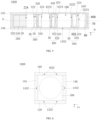
FIG. 1 is a structural schematic view of an optical lens in a long focal length state according to an embodiment of the present disclosure. -
FIG. 2 is a structural schematic view of an optical lens in a short focal length state according to an embodiment of the present disclosure. -
FIG. 3 is a perspective view of a camera module according to an embodiment of the present disclosure. -
FIG. 4 is an explosive view of the camera module shown inFIG. 3 . -
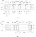
FIG. 5 is a cross section view of the camera module shown inFIG. 3 taken along a line V-V, wherein the optical lens is in a short focal length state. -
FIG. 6 is a cross section view of the camera module shown inFIG. 3 taken along a line VI-VI. -
FIG. 7 is a cross section view of the camera module shown inFIG. 3 taken along a line VII-VII, wherein the optical lens is in a short focal length state. -
FIG. 8 is a cross section view of the camera module according to an embodiment of the present disclosure, taken along a cross section line corresponding to the line VII-VII inFIG. 3 , wherein the optical lens is in a long focal length state. -
FIG. 9 is a planar schematic view of an image capturing device according to an embodiment of the present disclosure. -
FIG. 10 is a planar schematic view of an image capturing device from another viewing angle according to an embodiment of the present disclosure. - Embodiments of the present disclosure will be further described below by referring to the accompanying drawings. Same or similar reference numerals in the accompanying drawings indicate the same or similar components or components having the same or similar functions.
- In addition, the embodiments of the present disclosure described below by referring to the accompanying drawings are exemplary and are intended only to explain the embodiments of the present disclosure, but do not limit the present disclosure.
- In the present disclosure, unless otherwise expressively specified and limited, a first feature being "above" or "below" a second feature may be direct contact between the first feature and the second feature, or indirect contact between the first feature and the second feature through an intermediate medium. In addition, the first feature being "above", "on" and "on top of" the second feature may indicate the first feature being directly above or diagonally above the second feature, or simply indicate that the first feature is horizontally higher than the second feature. The first feature being "below", "under", and "at a bottom of" the second feature may indicate the first feature being directly below or diagonally below the second feature, or simply indicate that a horizontal height of the first feature is less than that of the second feature.
- As shown in
FIGS. 1 and 2 , the present disclosure provides anoptical lens 10. Along a direction from an object side to an imaging side, theoptical lens 10 successively includes aprism 20, afirst lens group 30, asecond lens group 40, and athird lens group 50. Theprism 20 is fixed relative to animaging surface 70 of theoptical lens 10. Afirst diaphragm 36 is disposed between thefirst lens group 30 and theprism 20. Asecond diaphragm 48 is disposed between thesecond lens group 40 and thethird lens group 50 or between thefirst lens group 30 and thesecond lens group 40. When theoptical lens 10 switches between a short focal length state and a long focal length state, theprism 20 is fixed, thefirst lens group 30 and thefirst diaphragm 36 are fixed relative to theprism 20, and thesecond lens group 40, thethird lens group 50, and thesecond diaphragm 48 move along an optical axis O of theoptical lens 10 relative to theprism 20. In this way, in the long focal length state, thefirst diaphragm 36 is an aperture diaphragm, and thesecond diaphragm 48 is a stray light elimination diaphragm. In the short focal length state, thesecond diaphragm 48 is an aperture diaphragm, and thefirst diaphragm 36 is a stray light elimination diaphragm. - In the present disclosure, the
optical lens 10 is arranged with thefirst diaphragm 36 and thesecond diaphragm 48. Thesecond diaphragm 48, thesecond lens group 40, and thethird lens group 50 are movable relative to theprism 20, such that, in the long focal length state, thefirst diaphragm 36 serves as the aperture diaphragm, and thesecond diaphragm 48 serves as the stray light elimination diaphragm; and in the short focal length state, thesecond diaphragm 48 serves as the aperture diaphragm, and thefirst diaphragm 36 serves as the stray light elimination diaphragm. In this way, a risk of stray light or vignetting of theoptical lens 10 is reduced, and the performance of theoptical lens 10 is improved. - In detail, as shown in
FIGS. 1 and 2 , theoptical lens 10 includes theprism 20, thefirst lens group 30, thesecond lens group 40, thethird lens group 50, thefirst diaphragm 36, thesecond diaphragm 48, afilter 60, and theimaging surface 70. Along the direction from the object side to the imaging side, theprism 20, the first lens group 30 (thefirst diaphragm 36 together with the first lens group 30), the second lens group 40 (thesecond diaphragm 48 together with the second lens group 40), thethird lens group 50, thefilter 60, and theimaging surface 70 are arranged successively. - The
prism 20 includes alight inlet surface 22, alight outlet surface 24, and areflective surface 26. External light is injected through thelight inlet surface 22 of theprism 20, reflected by thereflective surface 26 of theprism 20, then emitted to out of theprism 20 through thelight outlet surface 24, and reaches thefirst lens group 30. In the present embodiment, theprism 20 is a right-angle prism 20. For example, when theprism 20 is viewed from a side perpendicular to the optical axis O, theprism 20 is shown as a right triangle. Two sides at which two short sides of the right triangle of theprism 20 locate are thelight inlet surface 22 and thelight outlet surface 24, respectively. A side at which a long side of the right triangle of theprism 20 locates is thereflective surface 26. An angle between thelight inlet surface 22 and thereflective surface 26 may be 45 degrees, 30 degrees, 60 degrees, and the like. In the present embodiment, the angle between thelight inlet surface 22 and thereflective surface 26 is 45 degrees. In some embodiments, the external light may be reflected by thereflective surface 26 of theprism 20 to directly reach thefirst lens group 30 without passing through an inside of theprism 20. In this case, no light reaches thelight inlet surface 22 or thelight outlet surface 24. Thesurfaces prism 20, thefirst lens group 30, thesecond lens group 40, and thethird lens group 50 are co-axial, and an axis shared by these elements is the optical axis O. - The
first lens group 30 is spaced apart from and fixed relative to thelight outlet surface 24 of theprism 20. A center of thefirst lens group 30 locates on the optical axis O. Thefirst lens group 30 includes afirst lens 32 and asecond lens 34. Thefirst lens 32 and thesecond lens 34 are spaced apart and kept fixed relative to each other. A distance between thefirst lens 32 and thesecond lens 34 may be determined based on sizes of the two lenses, optical parameters, and the like, which is not limited by the present disclosure. In some embodiments, thefirst lens 32 and thesecond lens 34 are fixed arranged inside thefirst shell 320 by a transparent lens adhesive (shown inFIG. 5 ). In some embodiments, a transmission-enhancing film is disposed on at least one of thefirst lens 32 and thesecond lens 34, such that intensity of reflected light is reduced, and intensity of transmitted light is increased, allowing theoptical lens 10 to image more clearly. For example, the transmission-enhancing film may be disposed on an object side of thefirst lens 32 or an object side of thesecond lens 34. - A center of the
second lens group 40 locates on the optical axis O. Thesecond lens group 40 is movable along the optical axis O of theoptical lens 10 relative to theprism 20. Thesecond lens group 40 includes athird lens 42, afourth lens 44, and afifth lens 46 that are fixedly arranged in sequence. Thethird lens 42, thefourth lens 44, and thefifth lens 46 are spaced apart from each other and are kept fixed relative to each other. A distance between thethird lens 42 and thefourth lens 44, and a distance between thefourth lens 44 and thefifth lens 46 may be determined based on sizes of the lenses, optical parameters, and the like, which is not limited by the present disclosure. In some embodiments, thethird lens 42, thefourth lens 44 and thefifth lens 46 may be fixedly arranged inside asecond shell 420 by a transparent lens adhesive (shown inFIG. 5 ). In some embodiments, a transmission-enhancing film is disposed on at least one of thethird lens 42, thefourth lens 44 and thefifth lens 46, such that intensity of reflected light of the lenses is reduced, and intensity of transmitted light is increased, allowing theoptical lens 10 to image more clearly. For example, the transmission-enhancing film may be disposed on an object side of thethird lens 42, or an object side of thefourth lens 44, or an object side of thefifth lens 46, and so on, which will not be listed one by one hereinafter. - A center of the
third lens group 50 locates on the optical axis O. Thethird lens group 50 is movable along the optical axis O of theoptical lens 10 relative to theprism 20. Thethird lens group 50 includes asixth lens 52 and aseventh lens 54. Thesixth lens 52 and theseventh lens 54 are spaced apart from and are fixed relative to each other. A distance between thesixth lens 52 and theseventh lens 54 may be determined based on sizes of the lenses, optical parameters, and the like, which is not limited by the present disclosure. In some embodiments, thesixth lens 52 and theseventh lens 54 may be fixedly arranged inside athird shell 520 by a transparent lens adhesive (shown inFIG. 5 ). In some embodiments, a transmission-enhancing film is disposed on thesixth lens 52 and theseventh lens 54, such that intensity of reflected light of the lenses is reduced, and intensity of transmitted light is increased, allowing theoptical lens 10 to image more clearly. For example, the transmission-enhancing film may be disposed on an object side of thesixth lens 52, or an object side of theseventh lens 54, and so on, which will not be listed one by one hereinafter. Changing distances of thesecond lens group 40 and thethird lens group 50 relative to thefirst lens group 30 may allow theoptical lens 10 to switch between the long focal length state and the short focal length state. - Each of the
first lens 32, thesecond lens 34, thethird lens 42, thefourth lens 44, thefifth lens 46, thesixth lens 52, and theseventh lens 54 is a non-spheric lens. Thefirst lens 32, thesecond lens 34, thethird lens 42, thefourth lens 44, thefifth lens 46, thesixth lens 52, and theseventh lens 54 are made of transparent materials, such as glass, resin, plastic and the like. For example, all seven lenses may be made of glass or resin. Alternatively, some of the seven lenses may be made of glass, and the rest of the seven lenses may be made of resin. The present disclosure does not limit the materials for making the lenses. - Each of the
first diaphragm 36 and thesecond diaphragm 48 is a diaphragm having a fixed aperture size. A physical aperture size offirst diaphragm 36 is D1, and a physical aperture size ofsecond diaphragm 48 is D2. Thefirst diaphragm 36 is disposed between thefirst lens group 30 and theprism 20. Disposing thefirst diaphragm 36 between thefirst lens group 30 and theprism 20 may refer to thefirst diaphragm 36 disposed on thefirst lens group 30; or thefirst diaphragm 36 disposed on theprism 20; or thefirst diaphragm 36 disposed at any position in a space between thefirst lens group 30 and theprism 20. In the present embodiment, thefirst diaphragm 36 is disposed on the object side of thefirst lens 32. Thefirst diaphragm 36 and thefirst lens group 30 are fixedly arranged in thefirst shell 320 by glue, by snapping, and the like, such that thefirst diaphragm 36 is fixed relative to the first lens group 30 (as shown inFIG. 7 ). In other embodiments, thefirst diaphragm 36 may be disposed on thelight outlet surface 24 of theprism 20. In some embodiments, thefirst diaphragm 36 may be disposed on the object side of thesecond lens 34. In some embodiments, thefirst diaphragm 36 may be disposed in the space between thefirst lens 32 and thesecond lens 34. The present disclosure does not limit the position of thefirst diaphragm 36, as long as thefirst diaphragm 36 is disposed between thefirst lens group 30 and theprism 20. - The
second diaphragm 48 does not coincide with thefirst diaphragm 36. Thesecond diaphragm 48 is disposed between thesecond lens group 40 and thethird lens group 50 or between thefirst lens group 30 and thesecond lens group 40. In other words, thesecond diaphragm 48 is disposed at any position between thesecond lens 34 and theimaging surface 70, and thesecond diaphragm 48 may move along with thethird lens group 50. Disposing thesecond diaphragm 48 between thesecond lens group 40 and thethird lens group 50 may refer to thesecond diaphragm 48 being disposed on thesecond lens group 40; or thesecond diaphragm 48 being disposed on thethird lens group 50; or thesecond diaphragm 48 being disposed at any position in a space between thesecond lens group 40 and thethird lens group 50. Disposing thesecond diaphragm 48 between thefirst lens group 30 and thesecond lens group 40 may refer to thesecond diaphragm 48 being disposed on thesecond lens group 40; or thesecond diaphragm 48 being disposed on thefirst lens group 30; or thesecond diaphragm 48 being disposed at any position in a space between thesecond lens group 40 and thefirst lens group 30. In the present embodiment, thesecond diaphragm 48 is disposed between thefirst lens group 30 and thesecond lens group 40, and thesecond diaphragm 48 is disposed on the object side of thethird lens 42, such that thesecond diaphragm 48 moves along with the second lens group 40 (as shown inFIG. 7 , thesecond diaphragm 48 and thesecond lens group 40 may be fixed in thesecond shell 420 by glue, by snapping, and the like. Thesecond diaphragm 48 may be fixed relative to thesecond lens group 40. When thesecond shell 420 moves, thesecond diaphragm 48 and thesecond lens group 40 may move along with the second shell 420). In other embodiments, thesecond diaphragm 48 may be disposed in the space between thesecond lens 34 and thethird lens 42, and thesecond diaphragm 48 is fixed to thesecond lens group 40 and moves along with thesecond lens group 40. In some embodiments, thesecond diaphragm 48 may be disposed in the space between thesixth lens 52 and theseventh lens 54, and thesecond diaphragm 48 is fixed to thethird lens group 50 and moves along with thethird lens group 50. In some embodiments, thesecond diaphragm 48 may be disposed in the space between theseventh lens 54 and theimaging surface 70, and thesecond diaphragm 48 is fixed to thethird lens group 50 and moves along with the third lens group 50 (when thesecond diaphragm 48 moves along with thethird lens group 50, installation of thesecond diaphragm 48 and thethird lens group 50 may be referred to installation of thesecond diaphragm 48 and the second lens group 40). The present disclosure does not limit the position of thesecond diaphragm 48, as long as the position of thesecond diaphragm 48 and thefirst diaphragm 36 do not coincide with each other, and thesecond diaphragm 48 is disposed at any position in the space between thesecond lens 34 and theimaging surface 70. - The closer to the
prism 20 thefirst diaphragm 36 and thesecond diaphragm 48 are disposed, the smaller the radial sizes of thefirst lens 32, thesecond lens 34, thethird lens 42, thefourth lens 44, thefifth lens 46, thesixth lens 52, and theseventh lens 54 are. Therefore, the radial sizes of thefirst lens 32, thesecond lens 34, thethird lens 42, thefourth lens 44, thefifth lens 46, thesixth lens 52, and theseventh lens 54 may be adjusted by adjusting the positions of thefirst diaphragm 36 and thesecond diaphragm 48, such that theoptical lens 10 may be miniaturized. - The
filter 60 is an infrared filter and is disposed between theseventh lens 54 and theimaging surface 70. That is, thefilter 60 is disposed in the space between thethird lens group 50 and theimaging surface 70. - When the
optical lens 10 switches between the short focal length state (shown inFIG. 2 ) and the long focal length state (shown inFIG. 1 ), theprism 20 is fixed, thefirst lens group 30 and thefirst diaphragm 36 are fixed relative to theprism 20, and thesecond lens group 40, thesecond diaphragm 48, and thethird lens group 50 move along the optical axis O of theoptical lens 10 relative to theprism 20 or relative to thefirst lens group 30. In this way, in the long focal length state, thefirst diaphragm 36 serves as the aperture diaphragm, and thesecond diaphragm 48 serves as the stray light elimination diaphragm; and in the short focal length state, thesecond diaphragm 48 serves as the aperture diaphragm, and thefirst diaphragm 36 serves as the stray light elimination diaphragm. - When the
optical lens 10 is switched from the long focal length state to the short focal length state, theprism 20 is fixed, thefirst lens group 30 and thefirst diaphragm 36 are fixed relative to theprism 20, thethird lens group 50 moves from the imaging side to the object side along the optical axis O, and thesecond lens group 40 and thesecond diaphragm 48 move from the object side to the imaging side along the optical axis O. When theoptical lens 10 is switched from the short focal length state to the long focal length state, theprism 20 is fixed, thefirst lens group 30 and thefirst diaphragm 36 are fixed relative to theprism 20, thethird lens group 50 moves from the object side to the imaging side along the optical axis O, and thesecond lens group 40 and thesecond diaphragm 48 move from the imaging side to the object side along the optical axis O. - The physical aperture size of the
first diaphragm 36 is D1, and the physical aperture size of thesecond diaphragm 48 is D2. When theoptical lens 10 is in the long focal length state, a light beam aperture size at a location where thefirst diaphragm 36 is disposed is A1, and a light beam aperture size at a location where thesecond diaphragm 48 is disposed is A2. D1=A1, D2>A2, a focal length f=23mm, F/#=4.4, and a field of view angle is 20 degrees. When theoptical lens 10 is in the short focal length state, a light beam aperture size at a location where thefirst diaphragm 36 is disposed is B1, and a light beam aperture size at a location where thesecond diaphragm 48 is disposed is B2. D2=B2, D1>B1, the focal length f=14mm, F/#=3.2, and the field of view is 30.5 degrees. - As shown in
FIGS. 2 to 4 , thecamera module 1000 includes ashell 100, aprism assembly 200, afirst lens assembly 300, asecond lens assembly 400, and athird lens assembly 500, anoptical lens 10, and a lightsensitive element 600. Theprism 20 of theoptical lens 10 is mounted in theprism assembly 200, thefirst lens group 30 is mounted in thefirst lens assembly 300, thesecond lens group 40 is mounted in thesecond lens assembly 400, and thethird lens group 50 is mounted in thethird lens assembly 500. Theprism assembly 200, thefirst lens assembly 300, thesecond lens assembly 400, thethird lens assembly 500, thefilter 60, and the lightsensitive element 600 are successively arranged inside theshell 100. Theprism assembly 200 and thefirst lens assembly 300 are spaced apart from each other and fixedly arranged inside theshell 100. Thesecond lens assembly 400 and thethird lens assembly 500 are slidably arranged inside theshell 100, and are movable relative to thefirst lens assembly 300. Theimaging surface 70 of theoptical lens 10 is formed on a surface of the lightsensitive element 600 facing thethird lens assembly 500. In other words, the surface of the lightsensitive element 600 facing thethird lens assembly 500 serves as theimaging surface 70. The lightsensitive element 600 is opposite and fixed to theprism assembly 200. The lightsensitive element 600 is configured to convert a received light signal into an electrical signal. - In detail, as shown in
FIG. 3 andFIG. 4 , theshell 100 includes asubstrate 120, aside plate 140 and acover 160. Thesubstrate 120, theside plate 140 and thecover 160 cooperatively defines a receivingspace 180. Theprism assembly 200, thefirst lens assembly 300, thesecond lens assembly 400, thethird lens assembly 500 and the lightsensitive element 600 are received in the receivingspace 180. - As shown in
FIG. 4 , for subsequent description, a direction parallel to the optical axis O is defined as an x-direction, and a direction perpendicular to the x-direction is defined as a y-direction and a z-direction. Any two of the x-direction, y-direction and z-direction are perpendicular to each other. - The
substrate 120 includes a carryingsurface 122 for carrying theside plate 140. Thesubstrate 120 may be rectangular, cuboid, cylindrical, or a structure in other shapes, which will not be limited by the present disclosure. In the present embodiment, thesubstrate 120 is rectangular. - As shown in
FIG. 4 , theside plate 140 includes aninner surface 141, anouter surface 142, anupper surface 143, and alower surface 144. Theinner surface 141 is opposite to theouter surface 142. Theinner surface 141 is received in the receivingspace 180. Theouter surface 142 is exposed out of the receivingspace 180. Theinner surface 141 is connected to both theupper surface 143 and thelower surface 144. Theouter surface 142 is connected to both theupper surface 143 and thelower surface 144. Theupper surface 143 is opposite to thelower surface 144. Thelower surface 144 is attached to the carryingsurface 122 of thesubstrate 120, and theupper surface 143 is opposite to the carryingsurface 122 of thesubstrate 120. - As shown in
FIG. 6 , theside plate 140 further includes afirst side plate 145 and asecond side plate 146 that are parallel to the x-direction. In detail, a length direction of thefirst side plate 145 and a length direction of thesecond side plate 146 are parallel to the x-direction. Thefirst side plate 145 is opposite to thesecond side plate 146. Theinner surface 141 of thefirst side plate 145 and/or theinner surface 141 of thesecond side plate 146 defines aslide groove 1452 and a mountingslot 1454. For example, theinner surface 141 of thefirst side plate 145 defines theslide groove 1452 and the mountingslot 1454. Alternatively, theinner surface 141 of thesecond side plate 146 defines theslide groove 1452 and the mountingslot 1454. Alternatively, each of theinner surface 141 of thefirst side plate 145 and theinner surface 141 of thesecond side plate 146 defines theslide groove 1452 and the mountingslot 1454. In the present embodiment, each of theinner surface 141 of thefirst side plate 145 and theinner surface 141 of thesecond side plate 146 defines theslide groove 1452 and the mountingslot 1454, and an extending direction of theslide groove 1452 is parallel to the carryingsurface 122. - The
slide groove 1452 is communicated to the receivingspace 180. The extending direction of theslide groove 1452 is also parallel to the x-direction. A depth of theslide groove 1452 is less than a thickness of theside plate 140. That is, theslide groove 1452 does not penetrate through theouter surface 142 of theside plate 140. In other embodiments, theslide groove 1452 may penetrate through theouter surface 142 of theside plate 140 to allow the receivingspace 180 to be communicated to the outside. The number ofslide grooves 1452 defined in theinner surface 141 of thefirst side plate 145 and in the inner surface of thesecond side plate 146 may be one or more. For example, theinner surface 141 of thefirst side plate 145 defines oneslide groove 1452, and theinner surface 141 of thesecond side plate 146 defines oneslide groove 1452. In another example, theinner surface 141 of thefirst side plate 145 defines twoslide grooves 1452, and theinner surface 141 of thesecond side plate 146 defines twoslide grooves 1452. In still another example, theinner surface 141 of thefirst side plate 145 defines oneslide groove 1452, and theinner surface 141 of thesecond side plate 146 defines twoslide grooves 1452. The present disclosure will not list all the possibilities. In the present embodiment, each of theinner surface 141 of thefirst side plate 145 and theinner surface 141 of thesecond side plate 146 defines oneslide groove 1452. A shape of theslide groove 1452 intercepted by a plane perpendicular to the x-direction may be rectangular, semicircular, or in other shapes, such as other regular shapes or irregular shapes. As shown inFIG. 6 , in the present embodiment, theslide groove 1452 may be intercepted by the plane perpendicular to the x-direction into a D-shape. - The mounting
slot 1454 is communicated to the receivingspace 180. An end of the mountingslot 1454 extends through theupper surface 143 of theside plate 140, and the other end of the mountingslot 1454 is communicated to theslide groove 1452. An extension direction of the mountingslot 1454 may be perpendicular or inclined to the extension direction of theslide groove 1452. For example, the extension direction of the mountingslot 1454 is perpendicular to the x-direction. Alternatively, the extension direction of the mountingslot 1454 is inclined at a certain angle (not 0 degree, but may be 30 degrees, 60 degrees, 75 degrees, and the like) to the x-direction. In the present embodiment, the extension direction of the mountingslot 1454 is perpendicular to the x-direction. The number of mountingslots 1454 defined in theinner surface 141 of thefirst side plate 145 and in theinner surface 141 of thesecond side plate 146 may be one or more. For example, theinner surface 141 of thefirst side plate 145 defines one mountingslot 1454, and theinner surface 141 of thesecond side plate 146 defines one mountingslot 1454. In another example, theinner surface 141 of thefirst side plate 145 defines two mountingslots 1454, and theinner surface 141 of thesecond side plate 146 defines two mountingslots 1454. In still another example, theinner surface 141 of thefirst side plate 145 defines one mountingslot 1454, and theinner surface 141 of thesecond side plate 146 defines two mountingslots 1454. The present disclosure will not list all possibilities. In the present embodiment, each of theinner surface 141 of thefirst side plate 145 and theinner surface 141 of thesecond side plate 146 defines two mountingslots 1454. - As shown in
FIG. 4 , thecover 160 is disposed on theupper surface 143 of theside plate 140. In detail, thecover 160 may be mounted to theupper surface 143 of theside plate 140 by snapping, by screwing, by glue, and the like. Thecover 160 includes acover body 162 and anabutting portion 164. - The
cover body 162 is attached with theupper surface 143 of theside plate 140. Thecover body 162 defines alight inlet port 1622. A depth direction of thelight inlet port 1622 may be perpendicular to the x-direction, such that theentire camera module 1000 may be in a periscopic structure. The external light can be directed into the receivingspace 180 through thelight inlet port 1622. - The abutting
portion 164 is disposed on each of two sides of thecover body 162. In detail, one of the two sides of thecover body 162 corresponds to thefirst side plate 145, and the other one of the two sides of thecover body 162 corresponds to thesecond side plate 146. When thecover 160 is mounted on theside plate 140, the abuttingportion 164 is received in the mountingslot 1454. A length L of the abuttingportion 164 along the z-direction is equal to a depth H of the mountingslot 1454 along the z-direction. The abuttingportion 164 being received in the mountingslot 1454 may refer to the abuttingportion 164 being received in the mountingslot 1454 and occupying a partial space of the mountingslot 1454. The abuttingportion 164 being received in the mountingslot 1454 may also refer to the abuttingportion 164 being received in the mountingslot 1454 and occupying the entire space of the mountingslot 1454. In the present embodiment, when the abuttingportion 164 is received in the mountingslot 1454, the abuttingportion 164 occupies the entire space of the mountingslot 1454. The abuttingportion 164 is more firmly attached to a wall of the mountingslot 1454 to allow thecover 160 to be connected to theside plate 140 more stably. In other embodiments, the light inlet port is not a through hole, but a light-transmitting solid structure, and the light may be directed into the receivingspace 180 through the light-transmitting solid structure. - As shown in
FIGS. 4 ,5 , and7 , theprism assembly 200 is arranged inside theshell 100 and is received in the receivingspace 180. Theprism assembly 200 is opposite to thelight inlet port 1622 of thecover 160. Theprism assembly 200 includes aprism shell 220, theprism 20 of theoptical lens 10 of any of the above embodiments, and a mountingstage 240 for mounting theprism 20. Theprism 20 may be mounted inside theprism shell 220 by glue, by snapping, or the like. - In detail, the
prism shell 220 defines a light inlet throughhole 222 and a light outlet throughhole 224. The light inlet throughhole 222 faces thelight inlet port 1622 of thecover 160, and the light inlet throughhole 222 is communicated to thelight inlet port 1622 and an inside of theprism shell 220. The light outlet throughhole 222 faces theimaging surface 70 and is communicated to the receivingspace 180. The external light enters through thelight inlet port 1622, and passes through the light inlet throughhole 222 to reach thelight inlet surface 22 of theprism 20. Further, the light is reflected by thereflective surface 26 of theprism 20, and reaches an outside of thefirst lens assembly 300 through thelight outlet surface 24. Thelight outlet surface 24 of theprism 20 is perpendicular to the x-direction. Thereflective surface 26 of theprism 20 abuts against the carryingsurface 122 of thesubstrate 120. Theprism shell 220 defines an accommodating space for theprism 20 to be mounted. Theprism shell 220 may be mounted on the carryingsurface 122 by glue, by snapping, or the like. - The mounting
stage 240 is arranged inside theprism shell 220. In detail, the mountingstage 240 may be arranged inside theprism shell 220 by glue, by screwing, by snapping, or the like. The mountingstage 240 and theprism shell 220 may be an integral and overall component. Thereflective surface 26 of theprism 20 abuts against the mountingstage 240. Theprism 20 may also be fixed on the mountingstage 240 by glue, by snapping, or the like. - As shown in
FIGS. 4 ,5 , and7 , thefirst lens assembly 300 is received in the receivingspace 180 and is disposed between theprism 20 and theimaging surface 70. Thefirst lens assembly 300 is fixedly arranged inside theshell 100 and is spaced apart from theprism 20. Thefirst lens assembly 300 includes afirst shell 320, thefirst lens group 30 and thefirst diaphragm 36 of theoptical lens 10 in any of the above embodiments mounted inside thefirst shell 320. Thefirst lens group 30 and thefirst diaphragm 36 may be mounted inside thefirst shell 320 by glue, by snapping, or the like. Thefirst shell 320 may be mounted in the inside of theshell 100 by glue, by snapping, or the like. - The
first shell 320 defines a firstlight inlet port 322 and a firstlight outlet port 324 opposite to theprism 20. Thefirst shell 320 defines a firstaccommodating space 326 to receive thefirst lens assembly 30 and thefirst diaphragm 36. The firstaccommodating space 326 is communicated to the receivingspace 180 through the firstlight inlet port 322 and the firstlight outlet port 324. The firstlight inlet port 322 is opposite to the light outlet throughhole 224 of theprism assembly 200. The firstlight outlet port 324 is opposite to thesecond lens assembly 400. Thefirst lens assembly 30 and thefirst diaphragm 36 may be mounted inside thefirst shell 320 by glue, by snapping, or the like. - A lens in the
first lens group 142 is a part of a rotating body. For example, a lens in thefirst lens group 300 is firstly formed into a rotating body lens by a mold. Further, an edge of the rotating body lens is cut. A cutting ratio may be determined based on a size of an internal space of thecamera module 1000, optical parameters, and other factors, such that a lens (a face of the square shaped lens or the rectangular shaped lens that the optical axis O passes through is concaved or convexed) that is approximately square shaped or rectangular shaped is formed. Alternatively, lenses in thefirst lens group 30 are all made directly by a particular mold, and a cavity of the mold is a part of the rotating body, such that the lenses in thefirst lens group 30 are made directly. In this way, sizes of the lenses in thefirst lens group 30 are significantly reduced, such that an overall size of thecamera module 1000 is reduced, allowing thecamera module 1000 to be miniaturized. - As shown in
FIGS. 4 ,5 , and7 , thesecond lens assembly 400 is mounted inside theshell 100 and is received in the receivingspace 180. Thesecond lens assembly 400 is disposed between thefirst lens assembly 300 and theimaging surface 70. Thesecond lens assembly 400 is movable along the optical axis O relative to thefirst lens assembly 300. Thesecond lens assembly 400 includes asecond shell 420, thesecond lens group 40 and thesecond diaphragm 48 of theoptical lens 10 of any of the above implementations mounted inside thesecond shell 420. Thesecond lens group 40 and thesecond diaphragm 48 may be mounted to thesecond shell 420 by glue, by snapping, or the like. When thesecond shell 420 slides, thesecond shell 420 drives thesecond lens group 40 and thesecond diaphragm 48 to slide. - In detail, the
second shell 420 includes asecond body 422 and asecond slide block 424. Thesecond slide block 424 is fixedly connected to thesecond body 422. - The
second body 422 defines a secondlight inlet port 4222 and a secondlight outlet port 4224 corresponding to thesecond lens group 40. Thesecond body 422 defines a secondaccommodating space 440 to receive thesecond lens group 40 and thesecond diaphragm 48. The secondaccommodating space 440 is communicated to the receivingspace 180 through the secondlight inlet port 4222 and the secondlight outlet port 4224. The secondlight inlet port 4222 is opposite to the firstlight outlet port 324 of thefirst lens assembly 300, and the secondlight outlet port 4224 is opposite to thethird lens assembly 500. - The
second slide block 424 is disposed on a surface of thesecond body 422 that is opposite to theinner surface 141 of thefirst side plate 145 and/or theinner surface 141 of thesecond side plate 146. For example, thesecond slide block 424 is disposed on a surface of thesecond body 422 opposite to theinner surface 141 of thefirst side plate 145. Alternatively, thesecond slide block 424 is disposed on a surface of thesecond body 422 opposite to theinner surface 141 of thesecond side plate 146. Alternatively, thesecond slide block 424 is disposed on each of the surface of thesecond body 422 opposite to theinner surface 141 of thefirst side plate 145 and the surface of thesecond body 422 opposite to theinner surface 141 of thesecond side plate 146. In the present embodiment, thesecond slide block 424 is disposed on each of the surface of thesecond body 422 opposite to theinner surface 141 of thefirst side plate 145 and the surface of thesecond body 422 opposite to theinner surface 141 of thesecond side plate 146. Thesecond slide block 424 extends through the mountingslot 1454 to further slide into theslide groove 1452, such that thesecond slide block 424 is slidably received in theslide groove 1452. - As shown in
FIG.4 andFIG. 7 , the number of second slide blocks 424 matches the number of corresponding mountingslots 1454. The number of second slide blocks 424 matching the number of corresponding mountingslots 1454 may refer to the number of second slide blocks 424 disposed on the surface of thesecond body 422 opposite to theinner surface 141 of thefirst side plate 145 being equal to the number of mountingslots 1454 defined in theinner surface 141 of thefirst side plate 145, the number being two; and the number of second slide blocks 424 disposed on the surface of thesecond body 422 opposite to theinner surface 141 of thesecond side plate 146 being equal to the number of mountingslots 1454 defined in theinner surface 141 of thesecond side plate 146, the number being two. The two second slide blocks 424 are in one-to-one correspondence to the two mountingslots 1454. In other embodiments, the number of second slide blocks 424 may be less than the number of mountingslots 1454. For example, the number of second slide blocks 424 disposed on the surface of thesecond body 422 opposite to theinner surface 141 of thefirst side plate 145 is less than the number of mountingslots 1454 defined in theinner surface 141 of thefirst side plate 145, and the number of second slide blocks 424 disposed on the surface of thesecond body 422 opposite to theinner surface 141 of thesecond side plate 146 is less than the number of mountingslots 1454 defined in theinner surface 141 of thesecond side plate 146. Moreover, a length d1 of thesecond slide block 424 along the x-direction is less than or equal to a length d2 of the mountingslot 1454 along the x-direction, facilitating thesecond slide block 424 to extend through the mountingslot 1454 to further slide into theslide groove 1452. - A shape of the
second slide block 424 intercepted by the face perpendicular to the x-direction may be rectangular, semicircular, or in other shapes, such as other regular shapes or irregular shapes, as long as the shape of the second slide block 424 matches the shape of thecorresponding slide groove 1452. In detail, the shape of the second slide block 424 matching the shape of the corresponding slide groove 1452 may indicate that, when the slide groove 1452 defined in the inner surface 141 of the first side plate 145 is intercepted by the face perpendicular to the x-direction into the rectangular shape, the second slide block 424 disposed on the surface of the second body 422 opposite to the inner surface 141 of the first side plate 145 is also intercepted by the face perpendicular to the x-direction into the rectangular shape; when the slide groove 1452 defined in the inner surface 141 of the second side plate 146 is intercepted by the face perpendicular to the x-direction into the rectangular shape, the second slide block 424 disposed on the surface of the second body 422 opposite to the inner surface 141 of the second side plate 146 is also intercepted by the face perpendicular to the x-direction into the rectangular shape; when the slide groove 1452 defined in the inner surface 141 of the first side plate 145 is intercepted by the face perpendicular to the x-direction into the semicircular shape, the second slide block 424 disposed on the surface of the second body 422 opposite to the inner surface 141 of the first side plate 145 is also intercepted by the face perpendicular to the x-direction into the semicircular shape; and when the slide groove 1452 defined in the inner surface 141 of the second side plate 146 is intercepted by the face perpendicular to the x-direction into the semicircular shape, the second slide block 424 disposed on the surface of the second body 422 opposite to the inner surface 141 of the second side plate 146 is also intercepted by the face perpendicular to the x-direction into the semicircular shape. The present disclosure will not list all the possibilities. - As shown in
FIG. 6 , in the present embodiment, thesecond slide block 424 is intercepted by the face perpendicular to the x-direction into an irregular shape. The irregular shape is a closed "D" shape formed by a straight line and an arc. An outer wall of thesecond slide block 424 is intercepted into a shape corresponding to the arc of the "D" shape. The shape of thesecond slide block 424 matching the shape of thecorresponding slide groove 1452 may refer to a curvature of an arc corresponding to an inner wall of theslide groove 1452 being equal to a curvature of the arc corresponding to the outer wall of thesecond slide block 424. In this way, thesecond slide block 424 may match theslide groove 1452 more properly. - In the z-direction, two opposite ends of the
second slide block 424 abut against two opposite ends of the inner wall of theslide groove 1452. In detail, when thesecond slide block 424 is received in theslide groove 1452, in the z-direction, two opposite ends of thesecond slide block 424 corresponding to thefirst side plate 145 abut against two opposite ends of the inner wall of theslide groove 1452 defined in theinner surface 141 of thefirst side plate 145. Two opposite ends of thesecond slide block 424 corresponding to thesecond side plate 146 abut against two opposite ends of the inner wall of theslide groove 1452 defined in theinner surface 141 of thesecond side plate 146. In this way, movement of thesecond slide block 424 in the z-direction is limited, preventing thesecond slide block 424 from shaking or tilting in the z-direction and ensuring that imaging quality of thecamera module 1000 is not affected. - As shown in
FIGS. 4 and6 to 8 , in some embodiments, thesecond shell 420 further includes a secondbottom surface 426 and a secondtop surface 428 opposite to the secondbottom surface 426. The secondtop surface 428 is opposite to thecover 160. The secondbottom surface 426 is opposite to the carryingsurface 122 of thesubstrate 120. A groove-rail mating structure is configured between the secondbottom surface 426 and the carryingsurface 122 of thesubstrate 120 or between the secondtop surface 428 and thecover 160. In the present embodiment, the groove-rail mating structure is configured between the secondbottom surface 426 and the carryingsurface 122 of thesubstrate 120 and between the secondtop surface 428 and thecover 160. - In detail, the second
bottom surface 426 defines afirst recess 4262, and a surface of thesubstrate 120 opposite to the second bottom surface 426 (i.e., the carrying surface 122) is arranged with afirst slide rail 1222. Thesecond lens assembly 400 further includes afirst rolling ball 460, and thefirst rolling ball 460 is received in thefirst recess 4262 and abuts against a bottom of thefirst slide rail 1222. - A shape of the
first recess 4262 matches a shape of thefirst rolling ball 460. For example, thefirst rolling ball 460 is spherical, and a resistance against movement of thefirst rolling ball 460 may be relatively low. Thefirst recess 4262 is a semi-circular recess. A diameter of thefirst rolling ball 460 is equal to a diameter of thefirst recess 4262. That is, a half of thefirst rolling ball 460 is received in thefirst recess 4262. Thefirst rolling ball 460 is tightly received in thefirst recess 4262. While thefirst rolling ball 460 is moving, thefirst shell 320 of thesecond lens assembly 400 is driven to move. The carryingsurface 122 is arranged with thefirst slide rail 1222. Thefirst slide rail 1222 may be a recess defined in the carryingsurface 122 extending in a direction parallel to the x-direction. Thefirst slide rail 1222 may also be a protrusion disposed on the carryingsurface 122 extending in the direction parallel to the x-direction. A surface of the protrusion opposite to the secondbottom surface 426 of thesecond shell 420 defines a recess that receives thefirst rolling ball 460. In the present embodiment, thefirst slide rail 1222 is the recess defined in the carryingsurface 122 extending in the direction parallel to the x-direction. After thesecond lens assembly 400 is received in the receivingspace 180, a portion of thefirst rolling ball 460 is received in thefirst slide rail 1222 and abuts against a bottom of thefirst slide rail 1222. An inner wall of thefirst slide rail 1222 is intercepted by the face perpendicular to the x-direction into a first arc shape. An outer profile of thefirst rolling ball 460 is intercepted by the face perpendicular to the x-direction into a second arc shape. A curvature of the first arc shape is equal to a curvature of the second arc shape. While thefirst rolling ball 460 is rotating along thefirst slide rail 1222, in the y-direction, two opposite sides of an outer wall of thefirst rolling ball 460 abut against two opposite sides of an inner wall of thefirst slide rail 1222, such that movement of thefirst rolling ball 460 in the y-direction is limited, preventing thesecond lens assembly 400 from shaking or tilting in the y-direction. - The number of
first recesses 4262 is one or more. For example, the number offirst recesses 4262 may be one, two, three, four, or more. In the present embodiment, the number offirst recesses 4262 is four. The number of first rollingballs 460 may also be one or more. In the present embodiment, the number of first rollingballs 460 is equal to the number offirst recesses 4262, which is four. The fourfirst recesses 4262 are spaced apart each other and are defined in the secondbottom surface 426. - The number of
first slide rails 1222 may be one or more. The number offirst slide rails 1222 may be determined based on positions of the fourfirst recesses 4262. For example, when centers of the fourfirst recesses 4262 are in a straight line parallel to the x-direction, only onefirst slide rail 1222 needs to be defined. In another example, the fourfirst recesses 4262 are divided into two groups, each of the two groups includes twofirst recesses 4262. A line connecting centers of the twofirst recess 4262 in each of the two groups is parallel to the x direction, and the line connecting centers of the twofirst recess 4262 in one of the two groups does not coincide with the line connecting centers of the twofirst recess 4262 in the other one of the two groups, twofirst slide rails 1222 need to be defined, each of the twofirst slide rails 1222 corresponds to the twofirst recess 4262 in each of the two groups. In the present embodiment, fourfirst recesses 4262 are divided into two groups, each of the two groups includes twofirst recesses 4262. A line connecting centers of the twofirst recess 4262 in one of the two groups is parallel to a line connecting centers of the twofirst recess 4262 in the other one of the two groups, and the two lines are parallel to the x-direction. The fourfirst recesses 4262 may cooperatively define a rectangle. In this way, while four first rollingballs 460 are sliding in thefirst slide rail 1222, the four first rollingballs 460 are confined in the two first slide rails 1222. Since, in the y-direction, two opposite sides of the outer wall of each of the four first rollingballs 460 abut against two opposite sides of the inner wall of each of the twofirst slide rails 1222, thesecond lens assembly 400 may be prevented from shaking or tilting in the y-direction, ensuring that imaging quality of thecamera module 1000 is not affected. - As shown in
FIGS. 4 and6 to 8 , the secondtop surface 428 defines asecond recess 4282. Thesecond lens assembly 400 further includes asecond rolling ball 480. Thesecond rolling ball 480 is received in thesecond recess 4282 and abuts against thecover 160. - In detail, a shape of the
second recess 4282 matches a shape of thesecond rolling ball 480. For example, thesecond rolling ball 480 is spherical, and a resistance against movement of thesecond rolling ball 480 may be relatively low. Thesecond recess 4282 is a semi-circular recess. A diameter of thesecond rolling ball 480 is equal to a diameter of thesecond recess 4282. That is, a half of thesecond rolling ball 480 is received in thesecond recess 4282. Thesecond rolling ball 480 is tightly received in thesecond recess 4282. While thesecond rolling ball 480 is moving, the shell of thesecond lens assembly 400 is driven to move. The number ofsecond recesses 4282 is one or more. For example, the number ofsecond recesses 4282 may be one, two, three, four, or more. In the present embodiment, the number ofsecond recesses 4282 is four. The number of second rollingballs 480 may also be one or more. In the present embodiment, the number of second rollingballs 480 is equal to the number ofsecond recesses 4282, which is four. The foursecond recesses 4282 are spaced apart each other and are defined in the secondtop surface 428. Thesecond rolling ball 480 is received in thesecond recess 4282 and abuts against thecover 160, such that thesecond lens assembly 400 is confined between thecover 160 and thesubstrate 120, preventing thesecond lens assembly 400 from shaking or tilting in the z-direction, ensuring that the imaging quality is not affected. - As shown in
FIGS. 6 to 8 , a surface of thecover body 162 opposite to the secondtop surface 428 is arranged with asecond slide rail 1622. Thesecond rolling ball 480 is received in thesecond recess 4282 and abuts against a bottom of thesecond slide rail 1622. - In detail, the
second slide rail 1622 may be a recess defined in the surface of thecover body 162 opposite to the secondtop surface 428 and extends in the direction parallel to the x-direction. Thesecond slide rail 1622 may also be a protrusion disposed on the surface of thecover body 162 opposite to the secondtop surface 428 and extends in the direction parallel to the x-direction. A surface of the protrusion opposite to the secondtop surface 428 defines a recess that receives thesecond rolling ball 480. In the present embodiment, thesecond slide rail 1622 is the recess defined in the surface of thecover body 162 opposite to the secondtop surface 428 and extending in the direction parallel to the x-direction. After thesecond lens assembly 400 is received in the receivingspace 180, a portion of thesecond rolling ball 480 is received in thesecond slide rail 1622 and abuts against a bottom of thesecond slide rail 1622. An inner wall of thesecond slide rail 1622 is intercepted by the face perpendicular to the x-direction into a third arc shape. An outer profile of thesecond rolling ball 480 is intercepted by the face perpendicular to the x-direction into a fourth arc shape. A curvature of the third arc shape is equal to a curvature of the fourth arc shape. While thesecond rolling ball 480 is rotating along thesecond slide rail 1622, in the y-direction, two opposite sides of the outer wall of thesecond rolling ball 480 abut against two opposite sides of the inner wall of thesecond slide rail 1622, such that movement of thesecond rolling ball 480 in the y-direction is limited, preventing thesecond lens assembly 400 from shaking or tilting in the y-direction. - The number of
second slide rails 1622 may be one or more. The number of second slide rails 162 may be determined based on positions of the foursecond recesses 4282. For example, when centers of the foursecond recesses 4282 are in a straight line parallel to the x-direction, only onesecond slide rail 1622 needs to be defined. In another example, the foursecond recesses 4282 are divided into two groups, each of the two groups includes twosecond recesses 4282. A line connecting centers of the twosecond recess 4282 in each of the two groups is parallel to the x direction, and the line connecting centers of the twosecond recess 4282 in one of the two groups does not coincide with the line connecting centers of the twosecond recess 4282 in the other one of the two groups, twosecond slide rails 1622 need to be defined, each of the twosecond slide rails 1622 corresponds to the twosecond recess 4282 in each of the two groups. In the present embodiment, foursecond recesses 4282 are divided into two groups, each of the two groups includes twosecond recesses 4282. A line connecting centers of the twosecond recess 4282 in one of the two groups is parallel to a line connecting centers of the twosecond recess 4282 in the other one of the two groups, and the two lines are parallel to the x-direction. The foursecond recesses 4282 may cooperatively define a rectangle. In this way, while four second rollingballs 480 are sliding in thesecond slide rail 1622, the four second rollingballs 480 are confined in the two second slide rails 1622. Since, in the y-direction, two opposite sides of the outer wall of each of the four second rollingballs 480 abut against two opposite sides of the inner wall of each of the twosecond slide rails 1622, thesecond lens assembly 400 may be prevented from shaking or tilting in the y-direction, ensuring that imaging quality of thecamera module 1000 is not affected. - As shown in
FIGS. 4 to 7 , thethird lens assembly 500 is mounted inside theshell 100 and is received in the receivingspace 180. Thethird lens assembly 500 is disposed between thesecond lens assembly 400 and theimaging surface 70. Thethird lens assembly 500 is movable along the optical axis O relative to thefirst lens assembly 300. Thethird lens assembly 500 includes athird shell 520 and athird lens group 50 of theoptical lens 10 in any of the above embodiments mounted inside thethird shell 520. Thethird lens group 50 may be mounted inside thethird shell 520 by glue, by snapping, or the like. When thethird shell 520 is sliding, thethird shell 520 drives thethird lens group 50 to slide. - In detail, the
third shell 520 includes athird body 522 and athird slide block 524, and thethird slide block 524 is fixedly connected to thethird body 522. - The
third body 522 defines a thirdlight inlet port 5222 and a thirdlight outlet port 5224. The thirdlight inlet port 5222 corresponds to the secondlight outlet port 4224 and is opposite to theimaging surface 70. Thethird body 522 defines a thirdaccommodating space 540 to receive thethird lens group 50. The thirdaccommodating space 540 is communicated to the receivingspace 180 through the thirdlight inlet port 5222 and the thirdlight outlet port 5224. - Arrangement of the
third slide block 524 may be referred to thesecond slide block 424 and will not be repeatedly described herein. - As shown in
FIGS. 4 and6 to 8 , in some embodiments, thethird shell 520 further includes a thirdbottom surface 526 and a thirdtop surface 528 opposite to the thirdbottom surface 526. The thirdtop surface 528 is opposite to thecover 160. The thirdbottom surface 526 is opposite to the carryingsurface 122 of thesubstrate 120. A groove-rail mating structure is configured between the thirdbottom surface 526 and the carryingsurface 122 of thesubstrate 120 or between the thirdtop surface 528 and thecover 160. In the present embodiment, the groove-rail mating structure is configured between the thirdbottom surface 526 and the carryingsurface 122 of thesubstrate 120 and between the thirdtop surface 528 and thecover 160. - In detail, the third
bottom surface 526 defines athird recess 5262. Thethird lens assembly 500 further includes athird rolling ball 560. Thethird rolling ball 560 is received in thethird recess 5262 and abuts against the bottom of thefirst slide rail 1222. Connection between thethird rolling ball 560 and thethird shell 520 may be referred to the connection between thefirst rolling ball 460 and thesecond shell 420 and will not be repeatedly described herein. - The third
top surface 528 further defines afourth recess 5282. Thethird lens assembly 500 further includes afourth rolling ball 580. Thefourth rolling ball 580 is received in thefourth recess 5282 and abuts against the bottom of thesecond slide rail 1622. Connection between thefourth rolling ball 580 and thethird shell 520 may be referred to the connection between thesecond rolling ball 480 and thesecond shell 420 and will not be repeatedly described herein. - As shown in
FIGS. 4 and6 to 8 , in the present embodiment, theprism assembly 200, thefirst lens assembly 300, thesecond lens assembly 400, and thethird lens assembly 500 are disposed in sequence along the x-direction (from the object side to the imaging side) in the receivingspace 180. Theprism assembly 200 and thefirst lens assembly 300 are spaced apart from each other and are fixedly disposed on the carryingsurface 122 of thesubstrate 120, and theprism assembly 200 is opposite to thelight inlet port 1622 of thecover 160. Thesecond slide block 424 of thesecond lens assembly 400 extends through the mountingslot 1454 to further slide into theslide groove 1452. Thethird slide block 524 of thethird lens assembly 500 extends through the mountingslot 1454 to further slide into theslide groove 1452. In this way, thesecond slide block 424 and thethird slide block 524 are slidably received in theslide groove 1452, such that thesecond lens assembly 400 and thethird lens assembly 500 are slidably connected to theside plate 140. Thesecond slide block 424 is fixedly connected to thesecond body 422, and thethird slide block 524 is fixedly connected to thethird body 522. While thesecond slide block 424 and thethird slide block 524 are sliding in theslide groove 1452, thesecond body 422 drives thesecond lens group 40 to move, and thethird body 522 drives thethird lens group 50 to move. In this way, a relative distance between thesecond lens group 40 and theprism 20 is changed, and a relative distance between thethird lens group 50 and theprism 20 is changed. At the same time, a relative distance between thesecond lens group 40 and thefirst lens group 30 in the optical axis O and a relative distance between thethird lens group 50 and thefirst lens group 30 in the optical axis O are changed, allowing thecamera module 1000 to switch between the long focal length (as shown inFIG. 8 ) and the short focal length (as shown inFIG. 7 ). - After the
prism assembly 200, thefirst lens assembly 300, thesecond lens assembly 400 and thethird lens assembly 500 are mounted inside the receivingspace 180, thecover 160 is mounted theside plate 140, and the abuttingportion 164 of thecover 160 is completely received in the mountingslot 1454. It shall be understood that, while thecamera module 1000 is changing the focal length, thesecond slide block 424 or thethird slide block 524 passes over a position of theslide groove 1452 corresponding to the mountingslot 1454, thesecond slide block 424 or thethird slide block 524 do not abut against the inner wall of theslide groove 1452, and thesecond slide block 424 or thethird slide block 524 may shake or tilt in the z-direction. Therefore, after the abuttingportion 164 is completely received in the mountingslot 1454, the abuttingportion 164 may abut against thesecond slide block 424 or thethird slide block 524, preventing thesecond slide block 424 or thethird slide block 524 from shaking or tilting in the z-direction. - The
filter 60 is arranged inside theshell 100 and is disposed between thethird lens group 50 and the lightsensitive element 600. - The light
sensitive element 600 is disposed on theinner surface 141 of theside plate 140 of theshell 100 and is opposite to theprism assembly 200. The lightsensitive element 600 is configured to receive a light signal passing through theimaging surface 70 of theoptical lens 10 and to convert the light signal into an electrical signal. The lightsensitive element 600 may be a Complementary Metal Oxide Semiconductor (CMOS) lightsensitive element 600 or a Charge-coupled Device (CCD) lightsensitive element 600. - In some embodiments, the
camera module 1000 may include a drive structure. For example, the drive structure may be a magnetic drive structure received in the receivingspace 180. The magnetic drive structure includes a magnetic coil and a magnet. The magnetic coil may be disposed between theprism assembly 200 and thefirst lens assembly 300, or between thefirst lens assembly 300 and thesecond lens assembly 400, or between thethird lens assembly 500 and the lightsensitive element 600. The magnet may be disposed on thesecond body 422 of thesecond lens assembly 400 and thethird body 522 of thethird lens assembly 500. In the present embodiment, two magnetic coils are arranged. One of the two magnetic coils is disposed between theprism assembly 200 and thefirst lens assembly 300, and the other one of the two magnetic coils is disposed between thethird lens assembly 500 and the lightsensitive element 600. A magnet is disposed on thesecond body 422 of thesecond lens assembly 400, and another magnet is disposed on thethird body 522 of thethird lens assembly 500. When the magnetic coil disposed between theprism assembly 200 and thefirst lens assembly 300 is conductive, a corresponding magnetic field is generated to control thesecond body 422 arranged with the magnet to move away from or to approach the corresponding magnetic coil (thesecond slide block 424 moves alongslide groove 1452 away from or close to the corresponding magnetic coil). When the magnetic coil disposed between thethird lens assembly 500 and the lightsensitive element 600 is conductive, a corresponding magnetic field is generated to control thethird body 522 arranged with the magnet to move away from or to approach the corresponding magnetic coil (thethird slide block 524 moves alongslide groove 1452 away from or close to the corresponding magnetic coil). - In another example, the drive structure may be a linear motor. A stator of a first linear motor may be fixedly mounted on the
inner surface 141. A mover of the first linear motor extends from the stator and is connected to thesecond body 422. A stator of a second linear motor may also be fixedly mounted on theinner surface 141. A mover of the second linear motor extends from the stator and is connected to thethird body 522. When the mover of the first linear motor extends and retracts linearly, thesecond body 422 is driven to move linearly (thesecond slide block 424 slides in the slide groove 1452). When the mover of the second linear motor extends and retracts linearly, thethird body 522 is driven to move linearly (thethird slide block 524 slides in the slide groove 1452). The drive structure may also be a structure in other types, such as a hydraulic structure, a piezoelectric motor, and the like, which will not be listed completely in the present disclosure. - In the present disclosure, the
camera module 1000 is arranged with thefirst diaphragm 36 and thesecond diaphragm 48, and thesecond diaphragm 48, thesecond lens group 40 and thethird lens group 50 may move relative to theprism 20. In this way, in the long focal length state, thefirst diaphragm 36 serves as the aperture diaphragm, and thesecond diaphragm 48 serves as the stray light elimination diaphragm. In the short focal length state, thesecond diaphragm 48 serves as the aperture diaphragm, and thefirst diaphragm 36 serves as the stray light elimination diaphragm. In this way, a risk of stray light or vignetting of theoptical lens 10 is reduced, and the performance of theoptical lens 10 is improved. - As shown in
FIG. 9 andFIG. 10 , the present disclosure also provides animage capturing device 2000. Theimage capturing device 2000 includes thecamera module 1000 of any of the above embodiments and adevice shell 80. Thecamera module 1000 is mounted inside thedevice shell 80. - In detail, the
image capturing device 2000 includes adevice shell 80 and acamera module 1000. Thecamera module 1000 is connected to thedevice shell 80. Theimage capturing device 2000 may be a mobile phone, a tablet computer, a monitor, a laptop computer, a teller machine, a gate, a smart watch, a head display device, a gaming console, and the like. The present disclosure is illustrated by taking theimage capturing device 2000 being a mobile phone as an example. It shall be understood that, a specific form of theimage capturing device 2000 is not limited to a mobile phone. - The
device shell 80 may be configured for thecamera module 1000 to be mounted. In other words, thedevice shell 80 may serve as a carrier for thecamera module 1000. Theimage capturing device 2000 includes a front 82 and a rear 84. Thecamera module 1000 may be arranged on the front 82, serving as a front camera. Thecamera module 1000 may also be arranged on the rear 84, serving as a rear camera. In the present embodiment, thecamera module 1000 is arranged on the rear 84, serving as the rear camera. Thedevice shell 80 may further be configured for mounting thecamera module 1000, a power supply apparatus, a communication apparatus and other functional modules of theimage capturing device 2000, such that thedevice shell 80 provides protection for the functional modules against dust, dropping, water, and the like. - As shown in
FIG. 7 and FIG. 8 , in an imaging process, the light passes through thelight inlet port 1622 of thecover 160 to reach an inside of theshell 100, and passes through the light inlet throughhole 222 of theprism assembly 200 to reach thelight inlet surface 22 of theprism 20. The light is reflected by theprism 20, and passes through thelight outlet surface 22 of theprims 20 and the light outlet throughhole 224 to reach an outside. Further, the light successively passes through thefirst lens group 30, thesecond lens group 40, thethird lens group 50, and thelight filter 60, and at last reaching the lightsensitive element 600 for imaging. In thecamera module 1000, the relative distance between thesecond lens group 40 and thefirst lens group 300 on the optical axis O may be changed by relative movement of thesecond slide block 424 in theslide groove 1452, and the relative distance between thesecond lens group 40 and thefirst lens group 300 on the optical axis O may be changed by relative movement of thesecond slide block 424 in theslide groove 1452, allowing theimage module 1000 to change the focal length. - In the present disclosure, the
image capturing device 2000 is arranged with thefirst diaphragm 36 and thesecond diaphragm 48, and thesecond diaphragm 48, thesecond lens group 40 and thethird lens group 50 may move relative to theprism 20. In this way, in the long focal length state, thefirst diaphragm 36 serves as the aperture diaphragm, and thesecond diaphragm 48 serves as the stray light elimination diaphragm. In the short focal length state, thesecond diaphragm 48 serves as the aperture diaphragm, and thefirst diaphragm 36 serves as the stray light elimination diaphragm. In this way, a risk of stray light or vignetting of theoptical lens 10 is reduced, and the performance of theoptical lens 10 is improved. - In the description of the present specification, terms "certain embodiments", "an embodiment", "some embodiments", "exemplary embodiments", "examples", "specific examples", or "some examples" means that specific features, structures, materials or properties described are included in at least one embodiments or examples in the present disclosure. In the present specification, the exemplary expressions of the above terms do not necessarily refer to one same embodiment or example. Further, specific features, specific structures, specific materials or specific properties described may be combined with any one or more of the embodiments or examples in a suitable manner.
- Terms "first" and "second" are used for descriptive purposes only and shall not be understood as indicating or implying relative importance or as implicitly specifying the number of technical features indicated. Therefore, the features defined by the "first" and the "second" may explicitly or implicitly include at least one of the described features. In the description of the present disclosure, "a plurality of" means at least two, such as two, three, unless otherwise expressively and specifically limited.
- Although embodiments of the present disclosure are shown and described above. It shall be understood that the above embodiments are exemplary and shall not be interpreted as limiting the scope of the present disclosure. An ordinary skilled person in the art can make variations, modifications, replacements and variants for the above embodiments within the scope of the present disclosure. The scope of the present disclosure is defined by the claims and their equivalents.
Claims (15)
- An optical lens (10), comprising: a prism (20), a first lens group (30), a second lens group (40), and a third lens group (50), that are successively arranged along a direction from an object side to an imaging side; wherein,the prism (20) is fixed relative to an imaging surface (70) of the optical lens (10);a first diaphragm (36) is disposed between the first lens group (30) and the prism (20);a second diaphragm (48) is disposed between the second lens group (40) and the third lens group (50) or between the first lens group (30) and the second lens group (40);when the optical lens (10) is switched between a short focal length state and a long focal length state, the prism (20) is fixed, the first lens group (30) and the first diaphragm (36) are fixed relative to the prism (20), and the second lens group (40), the third lens group (50) and the second diaphragm (48) move along an optical axis of the optical lens (10) relative to the prism (20);in the long focal length state, the first diaphragm (36) serves as an aperture diaphragm and the second diaphragm (48) serves as a stray light elimination diaphragm; andin the short focal length state, the second diaphragm (48) serves the aperture diaphragm, and the first diaphragm (36) serves as the stray light elimination diaphragm.
- The optical lens (10) according to claim 1, wherein,the first lens group (30) comprises a first lens (32) and a second lens (34) that are fixed relative to each other;the second lens group (40) comprises a third lens (42), a fourth lens (44), and a fifth lens (46) that are arranged successively and fixed relative to each other; andthe third lens group (50) comprises a sixth lens (52) and a seventh lens (54) that are fixed relative to each other.
- The optical lens (10) according to claim 2, wherein,the first diaphragm (36) is disposed on an object side of the first lens (32); andthe second diaphragm (48) is disposed on an object side of the third lens (42) and is capable of moving along with the second lens group (40), when the second diaphragm (48) is disposed between the first lens group (30) and the second lens group (40).
- The optical lens (10) according to claim 2, wherein,the first diaphragm (36) is disposed on an object side of the first lens (32); andthe second diaphragm (48) is disposed on an object side of the sixth lens (52) and is capable of moving along with the third lens group (50), when the second diaphragm (48) is disposed between the second lens group (40) and the third lens group (50).
- The optical lens (10) according to claim 3 or 4, wherein,a physical aperture size of the first diaphragm (36) is D1, a physical aperture size of the second diaphragm (48) is D2;when the optical lens (10) is in the long focal length state, a light beam aperture size at a location where the first diaphragm (36) is disposed is A1, and a light beam aperture size at a location where the second diaphragm (48) is disposed is A2, D1=A1, and D2>A2; andwhen the optical lens (10) is in the short focal length state, a light beam aperture size at a location where the first diaphragm (36) is disposed is B1, and a light beam aperture size at a location where the second diaphragm (48) is disposed is B2, D2=B2, and D1>B1.
- The optical lens (10) according to claim 2, wherein each of the first lens (32), the second lens (34), the third lens (42), the fourth lens (44), the fifth lens (46), the sixth lens (52), and the seventh lens (54) is a non-spherical lens.
- The optical lens (10) according to claim 2, wherein at least one of the first lens (32), the second lens (34), the third lens (42), the fourth lens (44), the fifth lens (46), the sixth lens (52), and the seventh lens (54) is arranged with a transmission-enhancing film.
- The optical lens (10) according to claim 1, wherein when the second diaphragm (48) is disposed between the first lens group (30) and the second lens group (40),when the optical lens (10) is switched from the long focal length state to the short focal length state, the third lens group (50) moves from the imaging side to the object side in a direction of the optical axis, and the second lens group (40) and the second diaphragm (48) move from the object side to the imaging side in the direction of the optical axis; andwhen the optical lens (10) is switched from the short focal length state to the long focal length state, the third lens group (50) moves from the object side to the imaging side in the direction of the optical axis, and the second lens group (40) and the second diaphragm (48) move from the imaging side to the object side in the direction of the optical axis.
- The optical lens (10) according to claim 1, wherein,when the optical lens (10) is in the long focal length state, a focal length f=23mm, F/#=4.4 and a field of view is 20 degrees; andwhen the optical lens (10) is in the short focal length state, a focal length f=14mm, F/#=3.2 and a field of view is 30.5 degrees.
- A camera module, comprising:the optical lens (10) of any one of claims 1-9; anda light sensitive element (600) disposed on the imaging side of the optical lens (10), wherein the light sensitive element (600) is configured receive a light signal passing through the optical lens (10) and to convert the light signal into an electrical signal.
- The camera module according to claim 10, whereinthe camera module comprises a shell (100), a prism assembly (200), a first lens assembly (300), a second lens assembly (400) and a third lens assembly (500);the prism (20) is arranged in the prism assembly (200), the first lens group (30) is arranged in the first lens assembly (300), the second lens group (40) is arranged in the second lens assembly (400), and the third lens group (50) is arranged in the third lens assembly (500);the prism assembly (200) and the first lens assembly (300) are spaced apart from each other and are fixedly arranged in the shell (100); andthe second lens assembly (400) and the third lens assembly (500) are slidably arranged in said shell (100) and are movable relative to the first lens assembly (300).
- The camera module according to claim 11, whereinthe shell (100) comprises a substrate (120), a side plate (140) and a cover (160);the substrate (120), the side plate (140) and the cover (160) cooperatively define a receiving space (180); andthe first lens assembly (300) is received in the receiving space (180), the first lens assembly (300) comprises a first shell (320), the first lens group (30) and the first diaphragm (36) are arranged inside the first shell (320).
- The camera module according to claim 12, whereinthe second lens assembly (400) is received in the receiving space (180);the second lens assembly (400) comprises a second shell (420), the second lens group (40) and the second diaphragm (48) are arranged on the second shell (420);the second diaphragm (48) and the second lens group (40) move along with the second shell (420) when the second shell (420) is moving.
- The camera module according to claim 12, wherein the side plate (140) comprises a first side plate (145) and a second side plate (146) opposite to the first side plate (145);at least one of an inner surface of the first side plate (145) and an inner face of the second side plate (146) defines a slide groove (1452) and a mounting slot (1454);the slide groove (1452) and the mounting slot (1454) are communicated with the receiving space (180), and an extending direction of the mounting slot (1454) is perpendicular to or inclined to an extending direction of the slide groove (1452).
- The camera module according to claim 14, wherein the second shell (420) comprises a second body (422) and a second slide block (424), the second slide block (424) is capable of extending through the mounting slot (1454) to be received into the slide groove (1452), and the second slide block (424) is slidable in the slide groove (1452).
Applications Claiming Priority (2)
| Application Number | Priority Date | Filing Date | Title |
|---|---|---|---|
| CN201910718291.0A CN112327467B (en) | 2019-08-05 | 2019-08-05 | Optical lens, camera module and shooting equipment |
| PCT/CN2020/107184 WO2021023234A1 (en) | 2019-08-05 | 2020-08-05 | Optical lens, camera module and photographing device |
Publications (3)
| Publication Number | Publication Date |
|---|---|
| EP4009093A1 EP4009093A1 (en) | 2022-06-08 |
| EP4009093A4 EP4009093A4 (en) | 2022-09-14 |
| EP4009093B1 true EP4009093B1 (en) | 2024-05-08 |
Family
ID=74319420
Family Applications (1)
| Application Number | Title | Priority Date | Filing Date |
|---|---|---|---|
| EP20849919.4A Active EP4009093B1 (en) | 2019-08-05 | 2020-08-05 | Optical lens and camera module |
Country Status (4)
| Country | Link |
|---|---|
| US (1) | US20220155565A1 (en) |
| EP (1) | EP4009093B1 (en) |
| CN (1) | CN112327467B (en) |
| WO (1) | WO2021023234A1 (en) |
Families Citing this family (1)
| Publication number | Priority date | Publication date | Assignee | Title |
|---|---|---|---|---|
| CN117596466B (en) * | 2024-01-19 | 2024-03-22 | 泸州合达源电子科技有限公司 | Camera module and electronic equipment |
Family Cites Families (17)
| Publication number | Priority date | Publication date | Assignee | Title |
|---|---|---|---|---|
| JPS5441333B2 (en) * | 1973-03-23 | 1979-12-07 | ||
| JP3864897B2 (en) * | 2002-12-02 | 2007-01-10 | コニカミノルタフォトイメージング株式会社 | Imaging lens device |
| JP4450600B2 (en) * | 2003-03-10 | 2010-04-14 | 日本電産コパル株式会社 | Zoom lens |
| JP2004348082A (en) * | 2003-05-26 | 2004-12-09 | Olympus Corp | Optical path bending optical system |
| JP4972900B2 (en) * | 2005-09-28 | 2012-07-11 | 株式会社ニコン | Zoom lens |
| CN100516965C (en) * | 2006-05-09 | 2009-07-22 | 索尼株式会社 | Zoom lens and imaging apparatus |
| US7768715B2 (en) * | 2007-02-21 | 2010-08-03 | Theia Technologies, Llc | Whole system zoom and varifocal lens with intermediate image |
| JP5270267B2 (en) * | 2008-09-04 | 2013-08-21 | シャープ株式会社 | Zoom lens, zoom lens unit, and electronic device |
| JP4790052B2 (en) * | 2009-08-31 | 2011-10-12 | キヤノン株式会社 | Zoom lens and imaging apparatus having the same |
| JP5506577B2 (en) * | 2010-07-14 | 2014-05-28 | キヤノン株式会社 | Optical system and optical equipment |
| JP6137818B2 (en) * | 2012-11-30 | 2017-05-31 | キヤノン株式会社 | Zoom lens and imaging apparatus having the same |
| CN103631017B (en) * | 2013-11-15 | 2016-01-06 | 广州市浩洋电子有限公司 | The optical system of the varifocal imaging lamp of a kind of LED |
| CN204241744U (en) * | 2014-11-03 | 2015-04-01 | 湖北久之洋红外系统股份有限公司 | A kind of eliminate stray light device for high-resolution large-viewing-field projection lens |
| JP6501495B2 (en) * | 2014-11-06 | 2019-04-17 | キヤノン株式会社 | Zoom lens and imaging device having the same |
| US10139601B2 (en) * | 2015-05-08 | 2018-11-27 | Samsung Electronics Co., Ltd. | Thin telephoto lens and image pickup apparatus including the same |
| CN105068228A (en) * | 2015-07-31 | 2015-11-18 | 瑞声声学科技(苏州)有限公司 | Miniature zooming optical system of large relative aperture |
| JP6818531B2 (en) * | 2016-12-05 | 2021-01-20 | キヤノン株式会社 | Imaging optical system and an imaging device having it |
-
2019
- 2019-08-05 CN CN201910718291.0A patent/CN112327467B/en active Active
-
2020
- 2020-08-05 WO PCT/CN2020/107184 patent/WO2021023234A1/en unknown
- 2020-08-05 EP EP20849919.4A patent/EP4009093B1/en active Active
-
2022
- 2022-02-02 US US17/591,403 patent/US20220155565A1/en active Pending
Also Published As
| Publication number | Publication date |
|---|---|
| WO2021023234A1 (en) | 2021-02-11 |
| CN112327467B (en) | 2022-02-18 |
| US20220155565A1 (en) | 2022-05-19 |
| EP4009093A4 (en) | 2022-09-14 |
| CN112327467A (en) | 2021-02-05 |
| EP4009093A1 (en) | 2022-06-08 |
Similar Documents
| Publication | Publication Date | Title |
|---|---|---|
| US10564442B2 (en) | Apparatus for driving optical-reflector for OIS with multi-axial structure | |
| CN111158103B (en) | Zoom lens, camera module and electronic device | |
| CN107041156B (en) | Lens assembly and actuator for optical system and method thereof | |
| WO2021136280A1 (en) | Zoom lens, camera module, and electronic device | |
| KR102500987B1 (en) | Lens Actuator | |
| CN110764232A (en) | Optical lens and electronic device | |
| CN111123490B (en) | Zoom lens, imaging module and electronic equipment | |
| WO2021052345A1 (en) | Imaging method, imaging module and electronic device | |
| KR101862228B1 (en) | Apparatus for driving optical-reflector for ois | |
| CN115542510A (en) | Lens driving apparatus and camera module including the same | |
| CN110737077A (en) | Optical lens and electronic device | |
| US20240134149A1 (en) | Imaging lens module and electronic device | |
| KR20230079320A (en) | Lens Actuator and Camera module including the same | |
| US20220155565A1 (en) | Optical lens, camera module and image capturing device | |
| CN115943344A (en) | camera module | |
| CN112612127B (en) | Zoom lens, imaging module and electronic equipment | |
| US20220155553A1 (en) | Imaging device and electronic device | |
| KR102423685B1 (en) | Apparatus for operating lens | |
| US20220397807A1 (en) | Image capturing unit, camera module and electronic device | |
| KR20220162522A (en) | Camera actuator and camera module including the same | |
| KR20220066697A (en) | Optical system and camera module | |
| KR101945710B1 (en) | Apparatus for driving optical-reflector for ois | |
| CN111796386A (en) | Optical imaging device | |
| CN216083227U (en) | Imaging lens driving module and electronic device | |
| JP2023170184A (en) | Camera module |
Legal Events
| Date | Code | Title | Description |
|---|---|---|---|
| STAA | Information on the status of an ep patent application or granted ep patent |
Free format text: STATUS: THE INTERNATIONAL PUBLICATION HAS BEEN MADE |
|
| PUAI | Public reference made under article 153(3) epc to a published international application that has entered the european phase |
Free format text: ORIGINAL CODE: 0009012 |
|
| STAA | Information on the status of an ep patent application or granted ep patent |
Free format text: STATUS: REQUEST FOR EXAMINATION WAS MADE |
|
| 17P | Request for examination filed |
Effective date: 20220303 |
|
| AK | Designated contracting states |
Kind code of ref document: A1 Designated state(s): AL AT BE BG CH CY CZ DE DK EE ES FI FR GB GR HR HU IE IS IT LI LT LU LV MC MK MT NL NO PL PT RO RS SE SI SK SM TR |
|
| A4 | Supplementary search report drawn up and despatched |
Effective date: 20220816 |
|
| RIC1 | Information provided on ipc code assigned before grant |
Ipc: G02B 27/00 20060101ALN20220809BHEP Ipc: G02B 15/14 20060101AFI20220809BHEP |
|
| DAV | Request for validation of the european patent (deleted) | ||
| DAX | Request for extension of the european patent (deleted) | ||
| GRAP | Despatch of communication of intention to grant a patent |
Free format text: ORIGINAL CODE: EPIDOSNIGR1 |
|
| STAA | Information on the status of an ep patent application or granted ep patent |
Free format text: STATUS: GRANT OF PATENT IS INTENDED |
|
| INTG | Intention to grant announced |
Effective date: 20240228 |
|
| GRAS | Grant fee paid |
Free format text: ORIGINAL CODE: EPIDOSNIGR3 |
|
| GRAA | (expected) grant |
Free format text: ORIGINAL CODE: 0009210 |
|
| STAA | Information on the status of an ep patent application or granted ep patent |
Free format text: STATUS: THE PATENT HAS BEEN GRANTED |
|
| AK | Designated contracting states |
Kind code of ref document: B1 Designated state(s): AL AT BE BG CH CY CZ DE DK EE ES FI FR GB GR HR HU IE IS IT LI LT LU LV MC MK MT NL NO PL PT RO RS SE SI SK SM TR |
|
| REG | Reference to a national code |
Ref country code: GB Ref legal event code: FG4D |
|
| REG | Reference to a national code |
Ref country code: CH Ref legal event code: EP |
|
| REG | Reference to a national code |
Ref country code: DE Ref legal event code: R096 Ref document number: 602020030751 Country of ref document: DE |