EP4009036A1 - Method and apparatus for measuring three-dimensional refractive index tensor - Google Patents
Method and apparatus for measuring three-dimensional refractive index tensor Download PDFInfo
- Publication number
- EP4009036A1 EP4009036A1 EP21761599.6A EP21761599A EP4009036A1 EP 4009036 A1 EP4009036 A1 EP 4009036A1 EP 21761599 A EP21761599 A EP 21761599A EP 4009036 A1 EP4009036 A1 EP 4009036A1
- Authority
- EP
- European Patent Office
- Prior art keywords
- polarization
- incident light
- angle
- birefringence
- sample
- Prior art date
- Legal status (The legal status is an assumption and is not a legal conclusion. Google has not performed a legal analysis and makes no representation as to the accuracy of the status listed.)
- Granted
Links
Images

Classifications
-
- G—PHYSICS
- G01—MEASURING; TESTING
- G01N—INVESTIGATING OR ANALYSING MATERIALS BY DETERMINING THEIR CHEMICAL OR PHYSICAL PROPERTIES
- G01N21/00—Investigating or analysing materials by the use of optical means, i.e. using sub-millimetre waves, infrared, visible or ultraviolet light
- G01N21/17—Systems in which incident light is modified in accordance with the properties of the material investigated
- G01N21/41—Refractivity; Phase-affecting properties, e.g. optical path length
-
- G—PHYSICS
- G01—MEASURING; TESTING
- G01B—MEASURING LENGTH, THICKNESS OR SIMILAR LINEAR DIMENSIONS; MEASURING ANGLES; MEASURING AREAS; MEASURING IRREGULARITIES OF SURFACES OR CONTOURS
- G01B9/00—Measuring instruments characterised by the use of optical techniques
- G01B9/02—Interferometers
-
- G—PHYSICS
- G01—MEASURING; TESTING
- G01N—INVESTIGATING OR ANALYSING MATERIALS BY DETERMINING THEIR CHEMICAL OR PHYSICAL PROPERTIES
- G01N21/00—Investigating or analysing materials by the use of optical means, i.e. using sub-millimetre waves, infrared, visible or ultraviolet light
- G01N21/17—Systems in which incident light is modified in accordance with the properties of the material investigated
- G01N21/21—Polarisation-affecting properties
- G01N21/23—Bi-refringence
-
- G—PHYSICS
- G01—MEASURING; TESTING
- G01N—INVESTIGATING OR ANALYSING MATERIALS BY DETERMINING THEIR CHEMICAL OR PHYSICAL PROPERTIES
- G01N21/00—Investigating or analysing materials by the use of optical means, i.e. using sub-millimetre waves, infrared, visible or ultraviolet light
- G01N21/17—Systems in which incident light is modified in accordance with the properties of the material investigated
- G01N21/41—Refractivity; Phase-affecting properties, e.g. optical path length
- G01N21/45—Refractivity; Phase-affecting properties, e.g. optical path length using interferometric methods; using Schlieren methods
-
- G—PHYSICS
- G01—MEASURING; TESTING
- G01N—INVESTIGATING OR ANALYSING MATERIALS BY DETERMINING THEIR CHEMICAL OR PHYSICAL PROPERTIES
- G01N21/00—Investigating or analysing materials by the use of optical means, i.e. using sub-millimetre waves, infrared, visible or ultraviolet light
- G01N21/17—Systems in which incident light is modified in accordance with the properties of the material investigated
- G01N2021/178—Methods for obtaining spatial resolution of the property being measured
- G01N2021/1785—Three dimensional
- G01N2021/1787—Tomographic, i.e. computerised reconstruction from projective measurements
Definitions
- the following embodiments relate to a method and apparatus for measuring a three-dimensional (3-D) refractive index tensor, and more particularly, to a method and apparatus for measuring a 3-D refractive index tensor, which implements the restoration of 3-D birefringence.
- Optical diffraction tomography can quantitatively restore a distribution of 3-D refractive indices (RIs) of a sample in a non-destructive manner, and thus is applied and used in various fields, such as the check of a defect in a plastic lens and the measurement of a distribution of fine 3-D temperatures, as well as biological research such as a bacteria, a cell, and a tissue (Non-patent Document 1-3).
- RIs refractive indices
- Non-patent Documents 4 to 6 are precedent researches capable of measuring a two-dimensional (2-D) phase delay image for each polarization of a sample measured using a 2-D quantitative phase imaging technology. Korean
- Patent No. 10-1461235 describes a technology about a method of driving a probe for obtaining a polarization sensitivity-optical interference image for such a biological tissue test, a probe for detecting a polarization-sensitive optical interference image, and a polarization sensitivity-optical interference image system for a biological tissue test.
- Non-patent Document 4-6 Non-patent Document 4-6
- 2-D optical field image for each polarization according to a depth Korean Patent No. 10-1461235
- a theory or a methodology capable of measuring a 3-D refractive index tensor that is, a fundamental physical quantity of a sample that generates such a birefringence phenomenon, has not been known.
- Non-patent Document 1 Kim, K., et al. (2016). "Optical diffraction tomography techniques for the study of cell pathophysiology.”
- arXiv preprint arXiv:1603.00592 .
- Non-patent Document 2 Wolf, E. (1969). "Three-dimensional structure determination of semi-transparent objects from holographic data.” Optics Communications 1(4): 153-156 .
- Non-patent Document 3 Park, Y. (2016). “Quantitative phase imaging in biomedicine.” Nature Photonics 12(10): 578-589 .
- Non-patent Document 4 Colomb, T., Dahlgren, P., Beghuin, D., Cuche, E., Marquet, P., & Depeursinge, C. (2002). Polarization imaging by use of digital holography. Applied optics, 41(1), 27-37 .
- Non-patent Document 5 Wang, Z., Millet, L. J., Gillette, M. U., &ffy, G. (2008). Jones phase microscopy of transparent and anisotropic samples. Optics letters, 33(11), 1270-1272 .
- Non-patent Document 6 Kim, Y., Jeong, J., Jang, J., Kim, M. W., & Park, Y. (2012). Polarization holographic microscopy for extracting spatio-temporally resolved Jones matrix. Optics Express, 20(9), 9948-9955 .
- Embodiments describe a method and apparatus for measuring a three-dimensional (3-D) refractive index tensor, and more specifically, provide a technology capable of measuring an accurate birefringence value and a 3-D direction of molecules in a sample having birefringence.
- Embodiments provide a method and apparatus for measuring a 3-D refractive index tensor, which can accurately measure a distribution of 3-D birefringence of a sample including a birefringence material and also obtain information on a 3-D alignment direction of molecules.
- embodiments provide a method and apparatus for measuring a 3-D refractive index tensor, which can optically directly measure the results of interactions between molecules within a closed space and is capable of selective 3-D monitoring for a frame and a muscle fiber structure in a biological cell or a tissue sample without additional labeling, by monitoring a 3-D molecule alignment direction of liquid crystal drops.
- a method of measuring a three-dimensional (3-D) refractive index tensor may include controlling incident light having a plane wave based on at least one angle and a polarization, and measuring, in a polarization-dependent way, two-dimensional (2-D) diffraction light of a sample for the incident light incident at the at least one angle and with the polarization.
- a 3-D structure of a birefringence value and an alignment direction of molecules in the sample having birefringence may be measured.
- Controlling incident light having a plane wave based on at least one angle and a polarization may include controlling an angle of the incident light.
- Controlling an angle of the incident light may include controlling the angle of the incident light by using at least one of a dual mirror, a dual mirror, agalvanometric mirror, a deformable mirror, a digital micromirror device, a liquid-crystal spatial light modulator and a 2-D micro electro mechanical system mirror (MEMS mirror).
- a dual mirror a dual mirror
- agalvanometric mirror a deformable mirror
- a digital micromirror device a liquid-crystal spatial light modulator and a 2-D micro electro mechanical system mirror (MEMS mirror).
- MEMS mirror 2-D micro electro mechanical system mirror
- Controlling incident light having a plane wave based on at least one angle and a polarization may include controlling a polarization of the incident light.
- Controlling a polarization of the incident light may include controlling the polarization of the incident light by using at least one of a polarization beam splitter, an optical fiber polarization controller, a rotating polarization plate, a liquid-crystal retarder and a meta surface.
- Measuring 2-D diffraction light of a sample for the incident light in a polarization-dependent way may include using temporal and spatial intensity modulation interferometry including at least any one of Mach-Zehnder interferometry, phase shifting interferometry and a quantitative phase imaging unit or using a method of measuring the 2-D diffraction light using at least one of transport of intensity equation and Fourier ptychography.
- the 2-D diffraction light may be measured in a polarization-dependent way by using a rotating polarization plate, a liquid-crystal retarder, a meta surface, etc.
- the birefringence value and the alignment direction of molecules of the sample having birefringence may be restored into a single layer in a 3-D manner by diagonalizing a measured refractive index tensor by using a tensor feature of the birefringence value being a spatial rotation of the sample having birefringence.
- An apparatus for measuring a three-dimensional (3-D) refractive index tensor may include an incident light controller configured to control incident light having a plane wave based on at least one angle and a polarization, and a diffraction light measurement unit configured to measure, in a polarization-dependent way, two-dimensional (2-D) diffraction light of a sample for the incident light incident at the at least one angle and with the polarization.
- An incident light controller configured to control incident light having a plane wave based on at least one angle and a polarization
- a diffraction light measurement unit configured to measure, in a polarization-dependent way, two-dimensional (2-D) diffraction light of a sample for the incident light incident at the at least one angle and with the polarization.
- a 3-D structure of a birefringence value and an alignment direction of molecules in the sample having birefringence may be measured.
- the incident light controller may include an angle controller controlling an angle of the incident light, and a polarization controller controlling a polarization of the incident light.
- the birefringence value and the alignment direction of molecules of the sample having birefringence may be restored into a single layer in a 3-D manner by diagonalizing a measured refractive index tensor by using a tensor feature of the birefringence value being a spatial rotation of the sample having birefringence.
- the method and apparatus for measuring a 3-D refractive index tensor which can accurately measure a distribution of 3-D birefringence of a sample including a birefringence material and also obtain information on a 3-D alignment direction of molecules.
- the method and apparatus for measuring a 3-D refractive index tensor which can optically directly measure the results of interactions between molecules within a closed space and is capable of selective 3-D monitoring for a frame and a muscle fiber structure in a biological cell or a tissue sample without additional labeling, by monitoring a 3-D molecule alignment direction of liquid crystal drops.
- the following embodiments relate to a method and apparatus for measuring a 3-D refractive index tensor, and has an object of implementing the restoration of 3-D birefringence of a birefringence sample (sample) by theoretically expanding the existing optical diffraction tomography (ODT) technology.
- ODT optical diffraction tomography
- Embodiments relate to a technology which implements the restoration of 3-D birefringence. To this end, the point is to develop a theory which overcomes the limit of the existing theory and to develop measuring equipment for actually implementing a theory.
- the point of the development of the theory is to solve a vector wave equation based on a vector wave and a refractive index tensor without being limited to a scalar wave assumption, that is, the limit of the existing theory.
- a vector wave equation such as the following equation, may be derived within a material.
- k is the size of a wave vector
- n ⁇ is a refractive index tensor
- E is an electric field vector.
- the above wave equation may be represented as in the following equation by expressing the wave equation in the form of an inhomogeneous Helmholtz equation.
- Equation 2 In order to calculate the analytic solution of [Equation 2], Rytov approximation may be used.
- a wave surface In an Rytov method, a wave surface may be expressed as an exponent function.
- a weakly diffracted wave surface may be meaningfully approximated only up to the first degree among the expressions of a grade of an exponent, and may be represented as in the following equation.
- p o is a polarization vector of an plane wave of incident light
- ⁇ is a Dirac delta function
- a subscript 0 indicates a feature of the incident light
- a refractive index tensor needs to be a symmetric matrix. Accordingly, even in this embodiment, the refractive index tensor may assume a symmetric matrix having six components that need to be measured.
- a diffracted wave surface may be represented as a total of six vector components. However, since components of the two vertical polarization vectors are always dependent on each other, an underdetermined system including five independent equations and six parameters of a refractive index tensor is obtained.
- a fine inclination method may be provided.
- the location of scattering potential affecting the diffracted wave surface is F ⁇ ( k - k 0 ). Accordingly, the underdetermined system still remains because a scattering potential signal at a different location is measured when an incident angle is changed.
- a diffracted wave surface may be represented by using scattering potential before the angle is finely changed and a differential thereof.
- vector components vertical to the polarization of an incident light vector may be produced. This may be represented as in the following equation.
- F ⁇ k ⁇ k 0 ⁇ + ⁇ k ⁇ F ⁇ k ⁇ ⁇ k 0 ⁇ + ⁇ F ⁇ ⁇ k ⁇ k ⁇
- additional information necessary for the underdetermined system may be inputted from the measured vector wave surface by finely inclining the incident angle.
- a birefringence value and the alignment direction of molecules of a birefringence material may be restored into a single layer in a 3-D manner by diagonalizing a refractive index tensor measured by using a tensor feature of a birefringence value being based on the spatial rotation of the birefringence material.
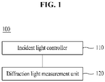
- FIG. 1 is a block diagram schematically illustrating an apparatus for measuring a 3-D refractive index tensor according to an embodiment.
- the point of an actual implementation of the present technology is to control incident light having a plane wave based on various angles and a polarization and to measure a scattered optical field in a polarization-dependent way.
- the existing optical diffraction tomography (ODT) technology controls the angle of incident light and measure corresponding scattering wave surfaces, but is different from the technology according to the present embodiments in that the polarization of incident light is controlled and a polarization-dependent wave surface is measured.
- ODT optical diffraction tomography
- An apparatus 100 for measuring a 3-D refractive index tensor may include an incident light controller 110 for controlling incident light having a plane wave based on at least one angle and a polarization, and a diffraction light measurement unit 120 for measuring 2-D diffraction light of a sample for incident light incident at at least one angle and with a polarization in a polarization-dependent way. Accordingly, the apparatus may measure a 3-D structure including a birefringence value and the alignment direction of molecules in a sample having birefringence.
- the apparatus 100 for measuring the 3-D refractive index tensor is more specifically described.
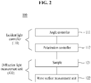
- FIG. 2 is a block diagram illustrating the apparatus for measuring a 3-D refractive index tensor according to an embodiment.
- the apparatus 100 for measuring a 3-D refractive index tensor may include the incident light controller 110 and the diffraction light measurement unit 120.
- the incident light controller 110 may include an angle controller 111 and a polarization controller 112.
- the diffraction light measurement unit 120 may include a wave surface measurement unit 122.
- the diffraction light measurement unit 120 may further include a sample 121.
- the incident light controller 110 may control incident light having a plane wave based on at least one angle and a polarization.
- the incident light controller 110 may include the angle controller 111.
- the angle controller 111 may control the angle of the incident light.
- a device capable of rapidly and stably controlling the angle of incident light includes a dual mirror, a galvanometric mirror, a deformable mirror, a digital micromirror device, a liquid-crystal spatial light modulator, a 2-D micro electro mechanical system mirror (MEMS mirror), etc.
- the angle of the incident light can be rapidly and stably controlled by moving the location of a dual mirror by using a motor, etc.
- the incident light controller 110 may further include the polarization controller 112.
- the polarization controller 112 may control the polarization of the incident light.
- a method of controlling the polarization of incident light includes methods using a polarization beam splitter, an optical fiber polarization controller, a rotating polarization plate, a liquid-crystal retarder, a meta surface, etc.
- the diffraction light measurement unit 120 may measure 2-D diffraction light (diffraction optical field) of the sample 121 for the incident light incident at at least one angle and with a polarization in a polarization-dependent way.
- temporal and spatial intensity modulation interferometry including Mach-Zehnder interferometry, phase shifting interferometry, a quantitative phase imaging unit, etc. may be used, or a method of measuring a 2-D diffraction optical field using transport of intensity equation, Fourier ptychography, etc. may be used.
- 2-D diffraction light may be measured in a polarization-dependent way by using a rotating polarization plate, a liquid-crystal retarder, a meta surface, etc.
- a rotating polarization plate, a liquid-crystal retarder, and a meta surface ahead of a camera may be used as in the aforementioned method of controlling the polarization of the incident light.
- the polarization-dependent optical field may be measured by using a polarization camera to which a polarization plate is attached ahead of a camera image sensor or using a polarization plate or a polarization beam splitter and two cameras in different directions at once.
- the 3-D structure of the birefringence sample 121 having the birefringence value and the alignment direction of molecules may be analyzed.
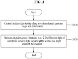
- FIG. 3 is a flowchart illustrating a method of measuring a 3-D refractive index tensor according to an embodiment.
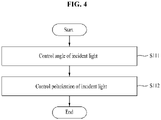
- FIG. 4 is a flowchart illustrating a method of controlling incident light having a plane wave based on an angle and a polarization according to an embodiment.
- the method of measuring a 3-D refractive index tensor may include a step S110 of controlling incident light having a plane wave based on at least one angle and a polarization, and a step S120 of measuring, in a polarization-dependent way, 2-D diffraction light of the sample 121 for the incident light incident at the at least one angle and with the polarization. Accordingly, a 3-D structure having a birefringence value and the alignment direction of molecules may be measured with respect to the sample 121 having birefringence.
- the step S110 of controlling incident light having a plane wave based on at least one angle and a polarization may include a step S111 of controlling the angle of the incident light and a step S112 of controlling the polarization of the incident light.
- a birefringence structure not measured by using the existing technology can be quantitatively imaged in a 3-D way.
- Label-free molecular-specific 3D imaging can be implemented by using a measured refractive index value and ratio.
- the method of measuring a 3-D refractive index tensor according to an embodiment may be described by taking, as an example, the apparatus 100 for measuring a 3-D refractive index tensor according to an embodiment described with reference to FIGS. 1 and 2 .
- the apparatus 100 for measuring a 3-D refractive index tensor according to an embodiment may include the incident light controller 110 and the diffraction light measurement unit 120.
- the incident light controller 110 may include the angle controller 111 and the polarization controller 112.
- the diffraction light measurement unit 120 may include the wave surface measurement unit 122.
- the incident light controller 110 may control the incident light having a plane wave based on the at least one angle and the polarization.
- the incident light controller 110 may control the angle of the incident light. To this end, the incident light controller 110 may control the angle of the incident light by using at least one of a dual mirror, a galvanometric mirror, a deformable mirror, a digital micromirror device, a liquid-crystal spatial light modulator, and a 2-D micro electro mechanical system mirror (MEMS mirror).
- a dual mirror a galvanometric mirror, a deformable mirror, a digital micromirror device, a liquid-crystal spatial light modulator, and a 2-D micro electro mechanical system mirror (MEMS mirror).
- MEMS mirror 2-D micro electro mechanical system mirror
- the incident light controller 110 may control the polarization of the incident light.
- the incident light controller 110 may control the polarization of the incident light by using at least one of a polarization beam splitter, an optical fiber polarization controller, a rotating polarization plate, a liquid-crystal retarder, and a meta surface.
- the diffraction light measurement unit 120 may measure, in a polarization-dependent way, 2-D diffraction light of the sample 121 for the incident light incident at the at least one angle and with the polarization.
- the diffraction light measurement unit 120 may use temporal and spatial intensity modulation interferometry, including at least any one of Mach-Zehnder interferometry, phase shifting interferometry and a quantitative phase imaging unit or may use a method of measuring 2-D diffraction light using at least one of transport of intensity equation and Fourier ptychography.
- a 3-D structure having a birefringence value and the alignment direction of molecules can be measured with respect to the sample 121 having birefringence.
- a birefringence value and the alignment direction of molecules of the sample 121 having birefringence may be restored into a single layer in a 3-D manner by diagonalizing a measured refractive index tensor by using a tensor feature of a birefringence value being based on the spatial rotation of the sample 121.
- FIG. 5 illustrates the results of measurement of a 3-D refractive index tensor according to an embodiment.
- a measured sample is a biological cell (A549 cell; lung cancer cell).
- a distribution of 3-D refractive indices of a sample including a birefringence material can be more accurately measured, and information on a 3-D alignment direction of molecules can also be obtained.
- the results of interactions between molecules within a closed space can be optically directly measured by monitoring a 3-D molecule alignment direction of liquid crystal drops which cannot be directly measured using the existing technologies.
- a frame and muscle fiber have a great polarization compared to surroundings.
- the embodiments may also be applied to selective 3-D monitoring of such a structure without additional labeling.
- the embodiments may also be effectively applied to the detection of a production failure in a small plastic lens, etc. because stress attributable to distortion, stretching, etc. in a produced plastic product causes an optical polarization feature.
- the aforementioned apparatus may be implemented as a hardware component, a software component and/or a combination of a hardware component and a software component.
- the apparatus and component described in the embodiments may be implemented using a processor, a controller, an arithmetic logic unit (ALU), a digital signal processor, a microcomputer, a field programmable gate array (FPGA), a programmable logic unit (PLU), a microprocessor or one or more general-purpose computers or special-purpose computers, such as any other apparatus capable of executing or responding to an instruction.
- the processing apparatus may perform an operating system (OS) and one or more software applications executed on the OS. Furthermore, the processing apparatus may access, store, manipulate, process and generate data in response to the execution of software.
- OS operating system
- the processing apparatus may access, store, manipulate, process and generate data in response to the execution of software.
- the processing apparatus may include a plurality of processing elements and/or a plurality of types of processing elements.
- the processing apparatus may include a plurality of processors or a single processor and a single controller.
- a different processing configuration such as a parallel processor, is also possible.
- Software may include a computer program, a code, an instruction or a combination of one or more of them, and may configure a processing apparatus so that the processing apparatus operates as desired or may instruct the processing apparatuses independently or collectively.
- the software and/or the data may be embodied in any type of machine, a component, a physical apparatus, a computer storage medium or a apparatus in order to be interpreted by the processor or to provide an instruction or data to the processing apparatus.
- the software may be distributed to computer systems connected over a network and may be stored or executed in a distributed manner.
- the software and the data may be stored in one or more computer-readable recording media.
- the method according to an embodiment may be implemented in the form of a program instruction executable by various computer means and recorded on a computer-readable recording medium.
- the computer-readable recording medium may include a program instruction, a data file, and a data structure alone or in combination.
- the program instruction recorded on the medium may be specially designed and constructed for an embodiment, or may be known and available to those skilled in the computer software field.
- Examples of the computer-readable medium include magnetic media such as a hard disk, a floppy disk and a magnetic tape, optical media such as a CD-ROM and a DVD, magneto-optical media such as a floptical disk, and hardware devices specially configured to store and execute a program instruction, such as a ROM, a RAM, and a flash memory.
- Examples of the program instruction include not only machine language code produced by a compiler, but a high-level language code which may be executed by a computer using an interpreter, etc.
Landscapes
- Physics & Mathematics (AREA)
- General Physics & Mathematics (AREA)
- General Health & Medical Sciences (AREA)
- Chemical & Material Sciences (AREA)
- Analytical Chemistry (AREA)
- Biochemistry (AREA)
- Life Sciences & Earth Sciences (AREA)
- Health & Medical Sciences (AREA)
- Immunology (AREA)
- Pathology (AREA)
- Investigating Or Analysing Materials By Optical Means (AREA)
- Optical Modulation, Optical Deflection, Nonlinear Optics, Optical Demodulation, Optical Logic Elements (AREA)
- Polarising Elements (AREA)
Abstract
Description
- The following embodiments relate to a method and apparatus for measuring a three-dimensional (3-D) refractive index tensor, and more particularly, to a method and apparatus for measuring a 3-D refractive index tensor, which implements the restoration of 3-D birefringence.
- Optical diffraction tomography (ODT) can quantitatively restore a distribution of 3-D refractive indices (RIs) of a sample in a non-destructive manner, and thus is applied and used in various fields, such as the check of a defect in a plastic lens and the measurement of a distribution of fine 3-D temperatures, as well as biological research such as a bacteria, a cell, and a tissue (Non-patent Document 1-3).
- However, the application of the existing ODT technology to a birefringence sample having a different refractive index depending on its direction has been limited because the technology requires a scalar wave assumption that all wave surfaces according to the vibration direction of an electric field of light are the same.
- Non-patent Documents 4 to 6 are precedent researches capable of measuring a two-dimensional (2-D) phase delay image for each polarization of a sample measured using a 2-D quantitative phase imaging technology. Korean
- Patent No.
10-1461235 - There was a technology capable of measuring a 2-D optical field image for each polarization of a sample having birefringence (Non-patent Document 4-6) or a 2-D optical field image for each polarization according to a depth (
Korean Patent No. 10-1461235 - (Non-patent Document 1) Kim, K., et al. (2016). "Optical diffraction tomography techniques for the study of cell pathophysiology." arXiv preprint arXiv:1603.00592.
- (Non-patent Document 2) Wolf, E. (1969). "Three-dimensional structure determination of semi-transparent objects from holographic data." Optics Communications 1(4): 153-156.
- (Non-patent Document 3) Park, Y. (2018). "Quantitative phase imaging in biomedicine." Nature Photonics 12(10): 578-589.
- (Non-patent Document 4) Colomb, T., Dahlgren, P., Beghuin, D., Cuche, E., Marquet, P., & Depeursinge, C. (2002). Polarization imaging by use of digital holography. Applied optics, 41(1), 27-37.
- (Non-patent Document 5) Wang, Z., Millet, L. J., Gillette, M. U., & Popescu, G. (2008). Jones phase microscopy of transparent and anisotropic samples. Optics letters, 33(11), 1270-1272.
- (Non-patent Document 6) Kim, Y., Jeong, J., Jang, J., Kim, M. W., & Park, Y. (2012). Polarization holographic microscopy for extracting spatio-temporally resolved Jones matrix. Optics Express, 20(9), 9948-9955.
- Embodiments describe a method and apparatus for measuring a three-dimensional (3-D) refractive index tensor, and more specifically, provide a technology capable of measuring an accurate birefringence value and a 3-D direction of molecules in a sample having birefringence.
- Embodiments provide a method and apparatus for measuring a 3-D refractive index tensor, which can accurately measure a distribution of 3-D birefringence of a sample including a birefringence material and also obtain information on a 3-D alignment direction of molecules.
- Furthermore, embodiments provide a method and apparatus for measuring a 3-D refractive index tensor, which can optically directly measure the results of interactions between molecules within a closed space and is capable of selective 3-D monitoring for a frame and a muscle fiber structure in a biological cell or a tissue sample without additional labeling, by monitoring a 3-D molecule alignment direction of liquid crystal drops.
- A method of measuring a three-dimensional (3-D) refractive index tensor according to an embodiment may include controlling incident light having a plane wave based on at least one angle and a polarization, and measuring, in a polarization-dependent way, two-dimensional (2-D) diffraction light of a sample for the incident light incident at the at least one angle and with the polarization. A 3-D structure of a birefringence value and an alignment direction of molecules in the sample having birefringence may be measured.
- Controlling incident light having a plane wave based on at least one angle and a polarization may include controlling an angle of the incident light.
- Controlling an angle of the incident light may include controlling the angle of the incident light by using at least one of a dual mirror, a dual mirror, agalvanometric mirror, a deformable mirror, a digital micromirror device, a liquid-crystal spatial light modulator and a 2-D micro electro mechanical system mirror (MEMS mirror).
- Controlling incident light having a plane wave based on at least one angle and a polarization may include controlling a polarization of the incident light.
- Controlling a polarization of the incident light may include controlling the polarization of the incident light by using at least one of a polarization beam splitter, an optical fiber polarization controller, a rotating polarization plate, a liquid-crystal retarder and a meta surface.
- Measuring 2-D diffraction light of a sample for the incident light in a polarization-dependent way may include using temporal and spatial intensity modulation interferometry including at least any one of Mach-Zehnder interferometry, phase shifting interferometry and a quantitative phase imaging unit or using a method of measuring the 2-D diffraction light using at least one of transport of intensity equation and Fourier ptychography. Furthermore, the 2-D diffraction light may be measured in a polarization-dependent way by using a rotating polarization plate, a liquid-crystal retarder, a meta surface, etc.
- The birefringence value and the alignment direction of molecules of the sample having birefringence may be restored into a single layer in a 3-D manner by diagonalizing a measured refractive index tensor by using a tensor feature of the birefringence value being a spatial rotation of the sample having birefringence.
- An apparatus for measuring a three-dimensional (3-D) refractive index tensor according to another embodiment may include an incident light controller configured to control incident light having a plane wave based on at least one angle and a polarization, and a diffraction light measurement unit configured to measure, in a polarization-dependent way, two-dimensional (2-D) diffraction light of a sample for the incident light incident at the at least one angle and with the polarization. A 3-D structure of a birefringence value and an alignment direction of molecules in the sample having birefringence may be measured.
- The incident light controller may include an angle controller controlling an angle of the incident light, and a polarization controller controlling a polarization of the incident light.
- The birefringence value and the alignment direction of molecules of the sample having birefringence may be restored into a single layer in a 3-D manner by diagonalizing a measured refractive index tensor by using a tensor feature of the birefringence value being a spatial rotation of the sample having birefringence.
- According to embodiments, there can be provided the method and apparatus for measuring a 3-D refractive index tensor, which can accurately measure a distribution of 3-D birefringence of a sample including a birefringence material and also obtain information on a 3-D alignment direction of molecules.
- Furthermore, according to embodiments, there can be provided the method and apparatus for measuring a 3-D refractive index tensor, which can optically directly measure the results of interactions between molecules within a closed space and is capable of selective 3-D monitoring for a frame and a muscle fiber structure in a biological cell or a tissue sample without additional labeling, by monitoring a 3-D molecule alignment direction of liquid crystal drops.
-
-
FIG. 1 is a block diagram schematically illustrating an apparatus for measuring a 3-D refractive index tensor according to an embodiment. -
FIG. 2 is a block diagram illustrating the apparatus for measuring a 3-D refractive index tensor according to an embodiment. -
FIG. 3 is a flowchart illustrating a method of measuring a 3-D refractive index tensor according to an embodiment. -
FIG. 4 is a flowchart illustrating a method of controlling incident light having a plane wave based on an angle and a polarization according to an embodiment. -
FIG. 5 illustrates the results of measurement of a 3-D refractive index tensor according to an embodiment. - Hereinafter, embodiments are described with reference to the accompanying drawings. However, the described embodiments may be modified in various other forms, and the scope of the present disclosure is not restricted by the following embodiments. Furthermore, various embodiments are provided to more fully describe the present disclosure to a person having average knowledge in the art. The shapes, sizes, etc. of elements in the drawings may be exaggerated for a clear description.
- The following embodiments relate to a method and apparatus for measuring a 3-D refractive index tensor, and has an object of implementing the restoration of 3-D birefringence of a birefringence sample (sample) by theoretically expanding the existing optical diffraction tomography (ODT) technology. Eventually, according to embodiments, a more accurate birefringence value and a 3-D direction of molecules can be measured in a sample having birefringence.
- Embodiments relate to a technology which implements the restoration of 3-D birefringence. To this end, the point is to develop a theory which overcomes the limit of the existing theory and to develop measuring equipment for actually implementing a theory.
- The development of the theory which overcomes the limit of the existing theory is first described below.
- The point of the development of the theory is to solve a vector wave equation based on a vector wave and a refractive index tensor without being limited to a scalar wave assumption, that is, the limit of the existing theory.
- Assuming a weakly scattering sample, a vector wave equation, such as the following equation, may be derived within a material.


E is an electric field vector. - The above wave equation may be represented as in the following equation by expressing the wave equation in the form of an inhomogeneous Helmholtz equation.

- Wherein
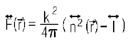
- In order to calculate the analytic solution of [Equation 2], Rytov approximation may be used. In an Rytov method, a wave surface may be expressed as an exponent function. A weakly diffracted wave surface may be meaningfully approximated only up to the first degree among the expressions of a grade of an exponent, and may be represented as in the following equation.

- Wherein

- An analytic solution calculated by using [Equation 2] as the Rytov approximation of [Equation 3] may be represented as in the following equation.

- Wherein
p o is a polarization vector of an plane wave of incident light, and δ is a Dirac delta function. Furthermore, asubscript 0 indicates a feature of the incident light. - According to energy conservation, it has been well known that a refractive index tensor needs to be a symmetric matrix. Accordingly, even in this embodiment, the refractive index tensor may assume a symmetric matrix having six components that need to be measured.
- Since two vertical polarization vectors may be defined for each incident light angle, a diffracted wave surface may be represented as a total of six vector components. However, since components of the two vertical polarization vectors are always dependent on each other, an underdetermined system including five independent equations and six parameters of a refractive index tensor is obtained.
- In order to solve such a problem, a fine inclination method may be provided. The location of scattering potential affecting the diffracted wave surface is F̃(
k -k0 ). Accordingly, the underdetermined system still remains because a scattering potential signal at a different location is measured when an incident angle is changed. However, if the incident angle is very finely changed, a diffracted wave surface may be represented by using scattering potential before the angle is finely changed and a differential thereof. Furthermore, vector components vertical to the polarization of an incident light vector may be produced. This may be represented as in the following equation.
- In the expression of [Equation 5], if a Fourier transform feature of a differential function is used, the following equation may be represented.

- Wherein F(
r )= IFT[F̃(k -k0 )]. - That is, additional information necessary for the underdetermined system may be inputted from the measured vector wave surface by finely inclining the incident angle.
- Finally, a birefringence value and the alignment direction of molecules of a birefringence material may be restored into a single layer in a 3-D manner by diagonalizing a refractive index tensor measured by using a tensor feature of a birefringence value being based on the spatial rotation of the birefringence material.
- Next, the development of measuring equipment for actually implementing the developed theory is described.
-
FIG. 1 is a block diagram schematically illustrating an apparatus for measuring a 3-D refractive index tensor according to an embodiment. - Referring to
FIG. 1 , the point of an actual implementation of the present technology is to control incident light having a plane wave based on various angles and a polarization and to measure a scattered optical field in a polarization-dependent way. - The existing optical diffraction tomography (ODT) technology controls the angle of incident light and measure corresponding scattering wave surfaces, but is different from the technology according to the present embodiments in that the polarization of incident light is controlled and a polarization-dependent wave surface is measured.
- An
apparatus 100 for measuring a 3-D refractive index tensor according to an embodiment may include anincident light controller 110 for controlling incident light having a plane wave based on at least one angle and a polarization, and a diffractionlight measurement unit 120 for measuring 2-D diffraction light of a sample for incident light incident at at least one angle and with a polarization in a polarization-dependent way. Accordingly, the apparatus may measure a 3-D structure including a birefringence value and the alignment direction of molecules in a sample having birefringence. - The
apparatus 100 for measuring the 3-D refractive index tensor is more specifically described. -
FIG. 2 is a block diagram illustrating the apparatus for measuring a 3-D refractive index tensor according to an embodiment. - Referring to
FIG. 2 , theapparatus 100 for measuring a 3-D refractive index tensor according to an embodiment may include theincident light controller 110 and the diffractionlight measurement unit 120. In this case,, theincident light controller 110 may include anangle controller 111 and apolarization controller 112. The diffractionlight measurement unit 120 may include a wavesurface measurement unit 122. Furthermore, according to an embodiment, the diffractionlight measurement unit 120 may further include asample 121. - The
incident light controller 110 may control incident light having a plane wave based on at least one angle and a polarization. - In this case, the
incident light controller 110 may include theangle controller 111. Theangle controller 111 may control the angle of the incident light. - A device capable of rapidly and stably controlling the angle of incident light includes a dual mirror, a galvanometric mirror, a deformable mirror, a digital micromirror device, a liquid-crystal spatial light modulator, a 2-D micro electro mechanical system mirror (MEMS mirror), etc. For example, the angle of the incident light can be rapidly and stably controlled by moving the location of a dual mirror by using a motor, etc.
- Furthermore, the
incident light controller 110 may further include thepolarization controller 112. Thepolarization controller 112 may control the polarization of the incident light. - A method of controlling the polarization of incident light includes methods using a polarization beam splitter, an optical fiber polarization controller, a rotating polarization plate, a liquid-crystal retarder, a meta surface, etc.
- The diffraction
light measurement unit 120 may measure 2-D diffraction light (diffraction optical field) of thesample 121 for the incident light incident at at least one angle and with a polarization in a polarization-dependent way. - In a method of measuring a 2-D diffraction optical field, temporal and spatial intensity modulation interferometry, including Mach-Zehnder interferometry, phase shifting interferometry, a quantitative phase imaging unit, etc. may be used, or a method of measuring a 2-D diffraction optical field using transport of intensity equation, Fourier ptychography, etc. may be used. Furthermore, 2-D diffraction light may be measured in a polarization-dependent way by using a rotating polarization plate, a liquid-crystal retarder, a meta surface, etc.
- In addition to the aforementioned methods of measuring a 2-D diffraction optical field, in order to measure the polarization-dependent optical field, a rotating polarization plate, a liquid-crystal retarder, and a meta surface ahead of a camera may be used as in the aforementioned method of controlling the polarization of the incident light. Furthermore, the polarization-dependent optical field may be measured by using a polarization camera to which a polarization plate is attached ahead of a camera image sensor or using a polarization plate or a polarization beam splitter and two cameras in different directions at once.
- After the 2-D diffraction optical field of the
sample 121 for the plane wave incident at various angles and in a polarization state is measured in a polarization-dependent way by using such methods, if the theory that overcomes the limit of the existing theory described above is used, the 3-D structure of thebirefringence sample 121 having the birefringence value and the alignment direction of molecules may be analyzed. -
FIG. 3 is a flowchart illustrating a method of measuring a 3-D refractive index tensor according to an embodiment. Furthermore,FIG. 4 is a flowchart illustrating a method of controlling incident light having a plane wave based on an angle and a polarization according to an embodiment. - Referring to
FIG. 3 , the method of measuring a 3-D refractive index tensor according to an embodiment may include a step S110 of controlling incident light having a plane wave based on at least one angle and a polarization, and a step S120 of measuring, in a polarization-dependent way, 2-D diffraction light of thesample 121 for the incident light incident at the at least one angle and with the polarization. Accordingly, a 3-D structure having a birefringence value and the alignment direction of molecules may be measured with respect to thesample 121 having birefringence. - Referring to
FIG. 4 , the step S110 of controlling incident light having a plane wave based on at least one angle and a polarization may include a step S111 of controlling the angle of the incident light and a step S112 of controlling the polarization of the incident light. - According to embodiments, a birefringence structure not measured by using the existing technology can be quantitatively imaged in a 3-D way. Label-free molecular-specific 3D imaging can be implemented by using a measured refractive index value and ratio.
- Each of the steps of the method of measuring a 3-D refractive index tensor according to an embodiment is more specifically described.
- The method of measuring a 3-D refractive index tensor according to an embodiment may be described by taking, as an example, the
apparatus 100 for measuring a 3-D refractive index tensor according to an embodiment described with reference toFIGS. 1 and2 . As described above, theapparatus 100 for measuring a 3-D refractive index tensor according to an embodiment may include theincident light controller 110 and the diffractionlight measurement unit 120. In this case, theincident light controller 110 may include theangle controller 111 and thepolarization controller 112. The diffractionlight measurement unit 120 may include the wavesurface measurement unit 122. - In step S120, the
incident light controller 110 may control the incident light having a plane wave based on the at least one angle and the polarization. - The
incident light controller 110 may control the angle of the incident light. To this end, theincident light controller 110 may control the angle of the incident light by using at least one of a dual mirror, a galvanometric mirror, a deformable mirror, a digital micromirror device, a liquid-crystal spatial light modulator, and a 2-D micro electro mechanical system mirror (MEMS mirror). - Furthermore, the
incident light controller 110 may control the polarization of the incident light. To this end, theincident light controller 110 may control the polarization of the incident light by using at least one of a polarization beam splitter, an optical fiber polarization controller, a rotating polarization plate, a liquid-crystal retarder, and a meta surface. - In step S120, the diffraction
light measurement unit 120 may measure, in a polarization-dependent way, 2-D diffraction light of thesample 121 for the incident light incident at the at least one angle and with the polarization. - In order to measure, in a polarization-dependent way, the 2-D diffraction light of the
sample 121 for the incident light, the diffractionlight measurement unit 120 may use temporal and spatial intensity modulation interferometry, including at least any one of Mach-Zehnder interferometry, phase shifting interferometry and a quantitative phase imaging unit or may use a method of measuring 2-D diffraction light using at least one of transport of intensity equation and Fourier ptychography. - Accordingly, a 3-D structure having a birefringence value and the alignment direction of molecules can be measured with respect to the
sample 121 having birefringence. A birefringence value and the alignment direction of molecules of thesample 121 having birefringence may be restored into a single layer in a 3-D manner by diagonalizing a measured refractive index tensor by using a tensor feature of a birefringence value being based on the spatial rotation of thesample 121. -
FIG. 5 illustrates the results of measurement of a 3-D refractive index tensor according to an embodiment. In this case, a measured sample is a biological cell (A549 cell; lung cancer cell). - According to embodiments, a distribution of 3-D refractive indices of a sample including a birefringence material can be more accurately measured, and information on a 3-D alignment direction of molecules can also be obtained.
- If embodiments are applied, the results of interactions between molecules within a closed space can be optically directly measured by monitoring a 3-D molecule alignment direction of liquid crystal drops which cannot be directly measured using the existing technologies. In a biological cell or a tissue sample, a frame and muscle fiber have a great polarization compared to surroundings. The embodiments may also be applied to selective 3-D monitoring of such a structure without additional labeling. Furthermore, it is expected that the embodiments may also be effectively applied to the detection of a production failure in a small plastic lens, etc. because stress attributable to distortion, stretching, etc. in a produced plastic product causes an optical polarization feature.
- The aforementioned apparatus may be implemented as a hardware component, a software component and/or a combination of a hardware component and a software component. For example, the apparatus and component described in the embodiments may be implemented using a processor, a controller, an arithmetic logic unit (ALU), a digital signal processor, a microcomputer, a field programmable gate array (FPGA), a programmable logic unit (PLU), a microprocessor or one or more general-purpose computers or special-purpose computers, such as any other apparatus capable of executing or responding to an instruction. The processing apparatus may perform an operating system (OS) and one or more software applications executed on the OS. Furthermore, the processing apparatus may access, store, manipulate, process and generate data in response to the execution of software. For convenience of understanding, one processing apparatus has been illustrated as being used, but a person having ordinary skill in the art may understand that the processing apparatus may include a plurality of processing elements and/or a plurality of types of processing elements. For example, the processing apparatus may include a plurality of processors or a single processor and a single controller. Furthermore, a different processing configuration, such as a parallel processor, is also possible.
- Software may include a computer program, a code, an instruction or a combination of one or more of them, and may configure a processing apparatus so that the processing apparatus operates as desired or may instruct the processing apparatuses independently or collectively. The software and/or the data may be embodied in any type of machine, a component, a physical apparatus, a computer storage medium or a apparatus in order to be interpreted by the processor or to provide an instruction or data to the processing apparatus. The software may be distributed to computer systems connected over a network and may be stored or executed in a distributed manner. The software and the data may be stored in one or more computer-readable recording media.
- The method according to an embodiment may be implemented in the form of a program instruction executable by various computer means and recorded on a computer-readable recording medium. The computer-readable recording medium may include a program instruction, a data file, and a data structure alone or in combination. The program instruction recorded on the medium may be specially designed and constructed for an embodiment, or may be known and available to those skilled in the computer software field. Examples of the computer-readable medium include magnetic media such as a hard disk, a floppy disk and a magnetic tape, optical media such as a CD-ROM and a DVD, magneto-optical media such as a floptical disk, and hardware devices specially configured to store and execute a program instruction, such as a ROM, a RAM, and a flash memory. Examples of the program instruction include not only machine language code produced by a compiler, but a high-level language code which may be executed by a computer using an interpreter, etc.
- As described above, although the embodiments have been described in connection with the limited embodiments and the drawings, those skilled in the art may modify and change the embodiments in various ways from the description. For example, proper results may be achieved although the aforementioned descriptions are performed in order different from that of the described method and/or the aforementioned components, such as a system, a structure, a device, and a circuit, are coupled or combined in a form different from that of the described method or replaced or substituted with other components or equivalents thereof.
- Accordingly, other implementations, other embodiments, and the equivalents of the claims fall within the scope of the claims.
Claims (10)
- A method of measuring a three-dimensional (3-D) refractive index tensor, comprising:controlling incident light having a plane wave based on at least one angle and a polarization; andmeasuring, in a polarization-dependent way, two-dimensional (2-D) diffraction light of a sample for the incident light incident at the at least one angle and with the polarization,wherein a 3-D structure of a birefringence value and an alignment direction of molecules in the sample having birefringence is measured.
- The method of claim 1, wherein controlling incident light having a plane wave based on at least one angle and a polarization comprises controlling an angle of the incident light.
- The method of claim 2, wherein controlling an angle of the incident light comprises controlling the angle of the incident light by using at least one of a dual mirror, a galvanometric mirror, a deformable mirror, a digital micromirror device, a liquid-crystal spatial light modulator and a 2-D micro electro mechanical system mirror (MEMS mirror).
- The method of claim 1, wherein controlling incident light having a plane wave based on at least one angle and a polarization comprises controlling a polarization of the incident light.
- The method of claim 4, wherein controlling a polarization of the incident light comprises controlling the polarization of the incident light by using at least one of a polarization beam splitter, an optical fiber polarization controller, a rotating polarization plate, a liquid-crystal retarder and a meta surface.
- The method of claim 1, wherein measuring 2-D diffraction light of a sample for the incident light in a polarization-dependent way comprises using temporal and spatial intensity modulation interferometry comprising at least any one of Mach-Zehnder interferometry, phase shifting interferometry and a quantitative phase imaging unit or using a method of measuring the 2-D diffraction light using at least one of transport of intensity equation and Fourier ptychography.
- The method of claim 1, wherein the birefringence value and the alignment direction of molecules of the sample having birefringence is restored into a single layer in a 3-D manner by diagonalizing a measured refractive index tensor by using a tensor feature of the birefringence value being a spatial rotation of the sample having birefringence.
- An apparatus for measuring a three-dimensional (3-D) refractive index tensor, comprising:an incident light controller configured to control incident light having a plane wave based on at least one angle and a polarization; anda diffraction light measurement unit configured to measure, in a polarization-dependent way, two-dimensional (2-D) diffraction light of a sample for the incident light incident at the at least one angle and with the polarization,wherein a 3-D structure of a birefringence value and an alignment direction of molecules in the sample having birefringence is measured.
- The apparatus of claim 8, wherein the incident light controller comprises:an angle controller controlling an angle of the incident light; anda polarization controller controlling a polarization of the incident light.
- The apparatus of claim 8, wherein the birefringence value and the alignment direction of molecules of the sample having birefringence is restored into a single layer in a 3-D manner by diagonalizing a measured refractive index tensor by using a tensor feature of the birefringence value being a spatial rotation of the sample having birefringence.
Applications Claiming Priority (2)
| Application Number | Priority Date | Filing Date | Title |
|---|---|---|---|
| KR1020200023424A KR102272149B1 (en) | 2020-02-26 | 2020-02-26 | Method and apparatus for retrieving three-dimensional refractive index tensor distribution |
| PCT/KR2021/000157 WO2021172734A1 (en) | 2020-02-26 | 2021-01-07 | Method and apparatus for measuring three-dimensional refractive index tensor |
Publications (4)
| Publication Number | Publication Date |
|---|---|
| EP4009036A1 true EP4009036A1 (en) | 2022-06-08 |
| EP4009036A4 EP4009036A4 (en) | 2023-07-26 |
| EP4009036B1 EP4009036B1 (en) | 2024-10-30 |
| EP4009036C0 EP4009036C0 (en) | 2024-10-30 |
Family
ID=76896791
Family Applications (1)
| Application Number | Title | Priority Date | Filing Date |
|---|---|---|---|
| EP21761599.6A Active EP4009036B1 (en) | 2020-02-26 | 2021-01-07 | Method and apparatus for measuring three-dimensional refractive index tensor |
Country Status (6)
| Country | Link |
|---|---|
| US (1) | US11821834B2 (en) |
| EP (1) | EP4009036B1 (en) |
| JP (1) | JP7273447B2 (en) |
| KR (1) | KR102272149B1 (en) |
| CN (1) | CN115104021B (en) |
| WO (1) | WO2021172734A1 (en) |
Families Citing this family (1)
| Publication number | Priority date | Publication date | Assignee | Title |
|---|---|---|---|---|
| US12587752B2 (en) | 2023-05-30 | 2026-03-24 | Duke University | Tensorial tomographic fourier ptychography |
Family Cites Families (18)
| Publication number | Priority date | Publication date | Assignee | Title |
|---|---|---|---|---|
| JPH08201277A (en) * | 1995-01-31 | 1996-08-09 | New Oji Paper Co Ltd | Birefringence measuring method and device |
| JPH11271536A (en) * | 1997-10-16 | 1999-10-08 | Matsushita Electric Ind Co Ltd | Image display device, polarized light illumination device, polarized light separating element, diffractive optical element, and hologram element, and methods for manufacturing diffractive optical element and hologram element |
| JP4629869B2 (en) * | 1998-02-20 | 2011-02-09 | ハインズ インスツルメンツ インコーポレイテッド | Birefringence characteristic measuring method and apparatus |
| JP4148592B2 (en) * | 1998-04-22 | 2008-09-10 | 株式会社リコー | Birefringence measuring method and birefringence measuring apparatus |
| JP4095932B2 (en) * | 2003-06-09 | 2008-06-04 | 日本分光株式会社 | Refractive index measuring device and refractive index measuring method |
| US7310145B2 (en) * | 2004-02-23 | 2007-12-18 | Ethicon, Inc. | Apparatus and method for determining optical retardation and birefringence |
| US7336359B1 (en) * | 2004-05-03 | 2008-02-26 | Purdue Research Foundation | System and method for nonlinear optical null ellipsometry |
| US7460248B2 (en) | 2006-05-15 | 2008-12-02 | Carestream Health, Inc. | Tissue imaging system |
| DE102007028371B4 (en) * | 2007-06-13 | 2012-05-16 | Seereal Technologies S.A. | Device for light modulation |
| KR101461235B1 (en) | 2008-02-29 | 2014-11-19 | 고려대학교 산학협력단 | Polarization sensitivity for biopsy - Probe for obtaining optical interference image and probe for detecting polarized light interference image and polarization sensitivity for biopsy - Method of driving optical interference image system |
| JP5287489B2 (en) * | 2008-06-05 | 2013-09-11 | 凸版印刷株式会社 | Three-dimensional refractive index measuring method and three-dimensional refractive index measuring apparatus |
| JP5321331B2 (en) * | 2009-08-03 | 2013-10-23 | 株式会社リコー | Optical scanning apparatus and image forming apparatus |
| JP2013246407A (en) * | 2012-05-29 | 2013-12-09 | Dainippon Printing Co Ltd | Optical sheet and display device |
| JP5786905B2 (en) * | 2013-07-18 | 2015-09-30 | 株式会社リコー | Optical scanning apparatus and image forming apparatus |
| DE102014013004A1 (en) * | 2013-09-06 | 2015-03-12 | Gerald Fütterer | Optical system for measuring polarization and phase |
| KR101865624B1 (en) * | 2016-06-10 | 2018-06-11 | 주식회사 토모큐브 | 3D Refractive Index Tomogram and Structured Illumination Microscopy System using Wavefront Shaper and Method thereof |
| KR101875515B1 (en) * | 2016-11-17 | 2018-07-10 | 주식회사 토모큐브 | Apparatus and Method for Diffraction Optical Tomography of Structured Illumination using Digital Micromirror Device |
| WO2018049476A1 (en) | 2016-09-15 | 2018-03-22 | La Trobe University | Determining complex refractive index values of a sample in three dimensions |
-
2020
- 2020-02-26 KR KR1020200023424A patent/KR102272149B1/en active Active
-
2021
- 2021-01-07 WO PCT/KR2021/000157 patent/WO2021172734A1/en not_active Ceased
- 2021-01-07 US US17/753,479 patent/US11821834B2/en active Active
- 2021-01-07 JP JP2022515547A patent/JP7273447B2/en active Active
- 2021-01-07 EP EP21761599.6A patent/EP4009036B1/en active Active
- 2021-01-07 CN CN202180005145.9A patent/CN115104021B/en active Active
Also Published As
| Publication number | Publication date |
|---|---|
| EP4009036A4 (en) | 2023-07-26 |
| JP2022547173A (en) | 2022-11-10 |
| KR102272149B1 (en) | 2021-07-02 |
| EP4009036B1 (en) | 2024-10-30 |
| JP7273447B2 (en) | 2023-05-15 |
| WO2021172734A1 (en) | 2021-09-02 |
| EP4009036C0 (en) | 2024-10-30 |
| US11821834B2 (en) | 2023-11-21 |
| CN115104021B (en) | 2025-10-03 |
| US20220404267A1 (en) | 2022-12-22 |
| CN115104021A (en) | 2022-09-23 |
Similar Documents
| Publication | Publication Date | Title |
|---|---|---|
| Merola et al. | Digital holography as a method for 3D imaging and estimating the biovolume of motile cells | |
| Balasubramani et al. | Roadmap on digital holography-based quantitative phase imaging | |
| Masia et al. | Quantitative chemical imaging and unsupervised analysis using hyperspectral coherent anti-Stokes Raman scattering microscopy | |
| Mirsky et al. | Dynamic tomographic phase microscopy by double six-pack holography | |
| Priscilla et al. | New avenues for phase imaging: optical metasurfaces | |
| EP4009036B1 (en) | Method and apparatus for measuring three-dimensional refractive index tensor | |
| Sardana et al. | Dielectric metasurface enabled compact, single-shot digital holography for quantitative phase imaging | |
| Zabolotna et al. | Processing and analysis of images in the multifunctional classification laser polarimetry system of biological objects | |
| Kou et al. | Real‐time parallel 3D multiple particle tracking with single molecule centrifugal force microscopy | |
| Xue et al. | Viscosity Measurement in Biocondensates Using Deep-Learning-Assisted Single-Particle Rotational Analysis | |
| Kinnunen et al. | Optical tweezers-assisted measurements of elastic light scattering | |
| Teixeira | Optical Tweezers: From automatic manipulation to multimodal sensing | |
| Pham et al. | Stokes–Mueller matrix polarimetry: effective parameters of anisotropic turbid media: theory and application | |
| Xu et al. | Optically trapped particle dynamic responses under varying frequency sinusoidal stimulus | |
| Miccio et al. | A new 3D tracking method for cell mechanics investigation exploiting the capabilities of digital holography in microscopy | |
| Català et al. | Momentum measurements with holographic optical tweezers for exploring force detection capabilities on irregular samples | |
| Zheng et al. | Illumination-Coded Optical Diffraction Tomography | |
| Fournier et al. | Numerical reconstruction of holograms using inverse problems approaches | |
| Singh et al. | Experimental investigations on the performance of dynamic binary hologram based trapped bead movement | |
| Merola et al. | 3D manipulation and visualization of in-vitro cells by optical tweezers and digital holographic microscopy | |
| Tomilin et al. | New polarizing optical microscope with additional functions based on a liquid-crystal space-time light modulator | |
| Kyeremah | Exploring Different Textures of Nematic Liquid Crystal Cells for Quantitative Fourier Phase Contrast Microscopy | |
| Hugonnet et al. | Dielectric-tensor reconstruction of highly scattering birefringent samples | |
| Streppa et al. | Tracking in real time the crawling dynamics of adherent living cells with a high resolution surface plasmon microscope | |
| Kundu et al. | Measurement of Van der Waals force using optical tweezers |
Legal Events
| Date | Code | Title | Description |
|---|---|---|---|
| STAA | Information on the status of an ep patent application or granted ep patent |
Free format text: STATUS: THE INTERNATIONAL PUBLICATION HAS BEEN MADE |
|
| PUAI | Public reference made under article 153(3) epc to a published international application that has entered the european phase |
Free format text: ORIGINAL CODE: 0009012 |
|
| STAA | Information on the status of an ep patent application or granted ep patent |
Free format text: STATUS: REQUEST FOR EXAMINATION WAS MADE |
|
| 17P | Request for examination filed |
Effective date: 20220302 |
|
| AK | Designated contracting states |
Kind code of ref document: A1 Designated state(s): AL AT BE BG CH CY CZ DE DK EE ES FI FR GB GR HR HU IE IS IT LI LT LU LV MC MK MT NL NO PL PT RO RS SE SI SK SM TR |
|
| RAP3 | Party data changed (applicant data changed or rights of an application transferred) |
Owner name: TOMOCUBE, INC. |
|
| DAV | Request for validation of the european patent (deleted) | ||
| DAX | Request for extension of the european patent (deleted) | ||
| A4 | Supplementary search report drawn up and despatched |
Effective date: 20230622 |
|
| RIC1 | Information provided on ipc code assigned before grant |
Ipc: G01N 21/17 20060101ALI20230616BHEP Ipc: G01B 9/02 20220101ALI20230616BHEP Ipc: G01N 21/23 20060101AFI20230616BHEP Ipc: G01N 21/41 20060101ALI20230616BHEP |
|
| GRAP | Despatch of communication of intention to grant a patent |
Free format text: ORIGINAL CODE: EPIDOSNIGR1 |
|
| STAA | Information on the status of an ep patent application or granted ep patent |
Free format text: STATUS: GRANT OF PATENT IS INTENDED |
|
| INTG | Intention to grant announced |
Effective date: 20240524 |
|
| GRAS | Grant fee paid |
Free format text: ORIGINAL CODE: EPIDOSNIGR3 |
|
| GRAA | (expected) grant |
Free format text: ORIGINAL CODE: 0009210 |
|
| STAA | Information on the status of an ep patent application or granted ep patent |
Free format text: STATUS: THE PATENT HAS BEEN GRANTED |
|
| AK | Designated contracting states |
Kind code of ref document: B1 Designated state(s): AL AT BE BG CH CY CZ DE DK EE ES FI FR GB GR HR HU IE IS IT LI LT LU LV MC MK MT NL NO PL PT RO RS SE SI SK SM TR |
|
| REG | Reference to a national code |
Ref country code: GB Ref legal event code: FG4D |
|
| REG | Reference to a national code |
Ref country code: CH Ref legal event code: EP |
|
| REG | Reference to a national code |
Ref country code: IE Ref legal event code: FG4D |
|
| REG | Reference to a national code |
Ref country code: DE Ref legal event code: R096 Ref document number: 602021021063 Country of ref document: DE |
|
| U01 | Request for unitary effect filed |
Effective date: 20241129 |
|
| U07 | Unitary effect registered |
Designated state(s): AT BE BG DE DK EE FI FR IT LT LU LV MT NL PT RO SE SI Effective date: 20250110 |
|
| U20 | Renewal fee for the european patent with unitary effect paid |
Year of fee payment: 5 Effective date: 20250121 |
|
| PG25 | Lapsed in a contracting state [announced via postgrant information from national office to epo] |
Ref country code: IS Free format text: LAPSE BECAUSE OF FAILURE TO SUBMIT A TRANSLATION OF THE DESCRIPTION OR TO PAY THE FEE WITHIN THE PRESCRIBED TIME-LIMIT Effective date: 20250228 Ref country code: HR Free format text: LAPSE BECAUSE OF FAILURE TO SUBMIT A TRANSLATION OF THE DESCRIPTION OR TO PAY THE FEE WITHIN THE PRESCRIBED TIME-LIMIT Effective date: 20241030 |
|
| PG25 | Lapsed in a contracting state [announced via postgrant information from national office to epo] |
Ref country code: ES Free format text: LAPSE BECAUSE OF FAILURE TO SUBMIT A TRANSLATION OF THE DESCRIPTION OR TO PAY THE FEE WITHIN THE PRESCRIBED TIME-LIMIT Effective date: 20241030 |
|
| PG25 | Lapsed in a contracting state [announced via postgrant information from national office to epo] |
Ref country code: NO Free format text: LAPSE BECAUSE OF FAILURE TO SUBMIT A TRANSLATION OF THE DESCRIPTION OR TO PAY THE FEE WITHIN THE PRESCRIBED TIME-LIMIT Effective date: 20250130 |
|
| PG25 | Lapsed in a contracting state [announced via postgrant information from national office to epo] |
Ref country code: GR Free format text: LAPSE BECAUSE OF FAILURE TO SUBMIT A TRANSLATION OF THE DESCRIPTION OR TO PAY THE FEE WITHIN THE PRESCRIBED TIME-LIMIT Effective date: 20250131 |
|
| PG25 | Lapsed in a contracting state [announced via postgrant information from national office to epo] |
Ref country code: PL Free format text: LAPSE BECAUSE OF FAILURE TO SUBMIT A TRANSLATION OF THE DESCRIPTION OR TO PAY THE FEE WITHIN THE PRESCRIBED TIME-LIMIT Effective date: 20241030 |
|
| PG25 | Lapsed in a contracting state [announced via postgrant information from national office to epo] |
Ref country code: RS Free format text: LAPSE BECAUSE OF FAILURE TO SUBMIT A TRANSLATION OF THE DESCRIPTION OR TO PAY THE FEE WITHIN THE PRESCRIBED TIME-LIMIT Effective date: 20250130 |
|
| PG25 | Lapsed in a contracting state [announced via postgrant information from national office to epo] |
Ref country code: SM Free format text: LAPSE BECAUSE OF FAILURE TO SUBMIT A TRANSLATION OF THE DESCRIPTION OR TO PAY THE FEE WITHIN THE PRESCRIBED TIME-LIMIT Effective date: 20241030 |
|
| PG25 | Lapsed in a contracting state [announced via postgrant information from national office to epo] |
Ref country code: SK Free format text: LAPSE BECAUSE OF FAILURE TO SUBMIT A TRANSLATION OF THE DESCRIPTION OR TO PAY THE FEE WITHIN THE PRESCRIBED TIME-LIMIT Effective date: 20241030 |
|
| PG25 | Lapsed in a contracting state [announced via postgrant information from national office to epo] |
Ref country code: CZ Free format text: LAPSE BECAUSE OF FAILURE TO SUBMIT A TRANSLATION OF THE DESCRIPTION OR TO PAY THE FEE WITHIN THE PRESCRIBED TIME-LIMIT Effective date: 20241030 |
|
| REG | Reference to a national code |
Ref country code: CH Ref legal event code: PL |
|
| PLBE | No opposition filed within time limit |
Free format text: ORIGINAL CODE: 0009261 |
|
| STAA | Information on the status of an ep patent application or granted ep patent |
Free format text: STATUS: NO OPPOSITION FILED WITHIN TIME LIMIT |
|
| PG25 | Lapsed in a contracting state [announced via postgrant information from national office to epo] |
Ref country code: MC Free format text: LAPSE BECAUSE OF FAILURE TO SUBMIT A TRANSLATION OF THE DESCRIPTION OR TO PAY THE FEE WITHIN THE PRESCRIBED TIME-LIMIT Effective date: 20241030 |
|
| 26N | No opposition filed |
Effective date: 20250731 |
|
| PG25 | Lapsed in a contracting state [announced via postgrant information from national office to epo] |
Ref country code: CH Free format text: LAPSE BECAUSE OF NON-PAYMENT OF DUE FEES Effective date: 20250131 |
|
| PG25 | Lapsed in a contracting state [announced via postgrant information from national office to epo] |
Ref country code: IE Free format text: LAPSE BECAUSE OF NON-PAYMENT OF DUE FEES Effective date: 20250107 |
|
| U20 | Renewal fee for the european patent with unitary effect paid |
Year of fee payment: 6 Effective date: 20260129 |
|
| PGFP | Annual fee paid to national office [announced via postgrant information from national office to epo] |
Ref country code: GB Payment date: 20260123 Year of fee payment: 6 |