EP4008985A1 - Subfreezing heat exchanger with separate melt fluid - Google Patents
Subfreezing heat exchanger with separate melt fluid Download PDFInfo
- Publication number
- EP4008985A1 EP4008985A1 EP21212244.4A EP21212244A EP4008985A1 EP 4008985 A1 EP4008985 A1 EP 4008985A1 EP 21212244 A EP21212244 A EP 21212244A EP 4008985 A1 EP4008985 A1 EP 4008985A1
- Authority
- EP
- European Patent Office
- Prior art keywords
- heat exchanger
- tube
- layer
- hot
- cold
- Prior art date
- Legal status (The legal status is an assumption and is not a legal conclusion. Google has not performed a legal analysis and makes no representation as to the accuracy of the status listed.)
- Granted
Links
Images


Classifications
-
- F—MECHANICAL ENGINEERING; LIGHTING; HEATING; WEAPONS; BLASTING
- F28—HEAT EXCHANGE IN GENERAL
- F28D—HEAT-EXCHANGE APPARATUS, NOT PROVIDED FOR IN ANOTHER SUBCLASS, IN WHICH THE HEAT-EXCHANGE MEDIA DO NOT COME INTO DIRECT CONTACT
- F28D9/00—Heat-exchange apparatus having stationary plate-like or laminated conduit assemblies for both heat-exchange media, the media being in contact with different sides of a conduit wall
- F28D9/0093—Multi-circuit heat-exchangers, e.g. integrating different heat exchange sections in the same unit or heat-exchangers for more than two fluids
-
- F—MECHANICAL ENGINEERING; LIGHTING; HEATING; WEAPONS; BLASTING
- F28—HEAT EXCHANGE IN GENERAL
- F28D—HEAT-EXCHANGE APPARATUS, NOT PROVIDED FOR IN ANOTHER SUBCLASS, IN WHICH THE HEAT-EXCHANGE MEDIA DO NOT COME INTO DIRECT CONTACT
- F28D9/00—Heat-exchange apparatus having stationary plate-like or laminated conduit assemblies for both heat-exchange media, the media being in contact with different sides of a conduit wall
- F28D9/0062—Heat-exchange apparatus having stationary plate-like or laminated conduit assemblies for both heat-exchange media, the media being in contact with different sides of a conduit wall the conduits for one heat-exchange medium being formed by spaced plates with inserted elements
-
- F—MECHANICAL ENGINEERING; LIGHTING; HEATING; WEAPONS; BLASTING
- F28—HEAT EXCHANGE IN GENERAL
- F28F—DETAILS OF HEAT-EXCHANGE AND HEAT-TRANSFER APPARATUS, OF GENERAL APPLICATION
- F28F17/00—Removing ice or water from heat-exchange apparatus
-
- F—MECHANICAL ENGINEERING; LIGHTING; HEATING; WEAPONS; BLASTING
- F28—HEAT EXCHANGE IN GENERAL
- F28F—DETAILS OF HEAT-EXCHANGE AND HEAT-TRANSFER APPARATUS, OF GENERAL APPLICATION
- F28F19/00—Preventing the formation of deposits or corrosion, e.g. by using filters or scrapers
- F28F19/006—Preventing deposits of ice
-
- F—MECHANICAL ENGINEERING; LIGHTING; HEATING; WEAPONS; BLASTING
- F28—HEAT EXCHANGE IN GENERAL
- F28F—DETAILS OF HEAT-EXCHANGE AND HEAT-TRANSFER APPARATUS, OF GENERAL APPLICATION
- F28F3/00—Plate-like or laminated elements; Assemblies of plate-like or laminated elements
- F28F3/02—Elements or assemblies thereof with means for increasing heat-transfer area, e.g. with fins, with recesses, with corrugations
-
- F—MECHANICAL ENGINEERING; LIGHTING; HEATING; WEAPONS; BLASTING
- F28—HEAT EXCHANGE IN GENERAL
- F28F—DETAILS OF HEAT-EXCHANGE AND HEAT-TRANSFER APPARATUS, OF GENERAL APPLICATION
- F28F9/00—Casings; Header boxes; Auxiliary supports for elements; Auxiliary members within casings
- F28F9/02—Header boxes; End plates
- F28F9/0234—Header boxes; End plates having a second heat exchanger disposed there within, e.g. oil cooler
-
- F—MECHANICAL ENGINEERING; LIGHTING; HEATING; WEAPONS; BLASTING
- F28—HEAT EXCHANGE IN GENERAL
- F28D—HEAT-EXCHANGE APPARATUS, NOT PROVIDED FOR IN ANOTHER SUBCLASS, IN WHICH THE HEAT-EXCHANGE MEDIA DO NOT COME INTO DIRECT CONTACT
- F28D1/00—Heat-exchange apparatus having stationary conduit assemblies for one heat-exchange medium only, the media being in contact with different sides of the conduit wall, in which the other heat-exchange medium is a large body of fluid, e.g. domestic or motor car radiators
- F28D1/02—Heat-exchange apparatus having stationary conduit assemblies for one heat-exchange medium only, the media being in contact with different sides of the conduit wall, in which the other heat-exchange medium is a large body of fluid, e.g. domestic or motor car radiators with heat-exchange conduits immersed in the body of fluid
- F28D1/04—Heat-exchange apparatus having stationary conduit assemblies for one heat-exchange medium only, the media being in contact with different sides of the conduit wall, in which the other heat-exchange medium is a large body of fluid, e.g. domestic or motor car radiators with heat-exchange conduits immersed in the body of fluid with tubular conduits
- F28D1/0408—Multi-circuit heat exchangers, e.g. integrating different heat exchange sections in the same unit or heat exchangers for more than two fluids
-
- F—MECHANICAL ENGINEERING; LIGHTING; HEATING; WEAPONS; BLASTING
- F28—HEAT EXCHANGE IN GENERAL
- F28D—HEAT-EXCHANGE APPARATUS, NOT PROVIDED FOR IN ANOTHER SUBCLASS, IN WHICH THE HEAT-EXCHANGE MEDIA DO NOT COME INTO DIRECT CONTACT
- F28D1/00—Heat-exchange apparatus having stationary conduit assemblies for one heat-exchange medium only, the media being in contact with different sides of the conduit wall, in which the other heat-exchange medium is a large body of fluid, e.g. domestic or motor car radiators
- F28D1/02—Heat-exchange apparatus having stationary conduit assemblies for one heat-exchange medium only, the media being in contact with different sides of the conduit wall, in which the other heat-exchange medium is a large body of fluid, e.g. domestic or motor car radiators with heat-exchange conduits immersed in the body of fluid
- F28D1/04—Heat-exchange apparatus having stationary conduit assemblies for one heat-exchange medium only, the media being in contact with different sides of the conduit wall, in which the other heat-exchange medium is a large body of fluid, e.g. domestic or motor car radiators with heat-exchange conduits immersed in the body of fluid with tubular conduits
- F28D1/053—Heat-exchange apparatus having stationary conduit assemblies for one heat-exchange medium only, the media being in contact with different sides of the conduit wall, in which the other heat-exchange medium is a large body of fluid, e.g. domestic or motor car radiators with heat-exchange conduits immersed in the body of fluid with tubular conduits the conduits being straight
- F28D1/05308—Assemblies of conduits connected side by side or with individual headers, e.g. section type radiators
-
- F—MECHANICAL ENGINEERING; LIGHTING; HEATING; WEAPONS; BLASTING
- F28—HEAT EXCHANGE IN GENERAL
- F28D—HEAT-EXCHANGE APPARATUS, NOT PROVIDED FOR IN ANOTHER SUBCLASS, IN WHICH THE HEAT-EXCHANGE MEDIA DO NOT COME INTO DIRECT CONTACT
- F28D1/00—Heat-exchange apparatus having stationary conduit assemblies for one heat-exchange medium only, the media being in contact with different sides of the conduit wall, in which the other heat-exchange medium is a large body of fluid, e.g. domestic or motor car radiators
- F28D1/02—Heat-exchange apparatus having stationary conduit assemblies for one heat-exchange medium only, the media being in contact with different sides of the conduit wall, in which the other heat-exchange medium is a large body of fluid, e.g. domestic or motor car radiators with heat-exchange conduits immersed in the body of fluid
- F28D1/04—Heat-exchange apparatus having stationary conduit assemblies for one heat-exchange medium only, the media being in contact with different sides of the conduit wall, in which the other heat-exchange medium is a large body of fluid, e.g. domestic or motor car radiators with heat-exchange conduits immersed in the body of fluid with tubular conduits
- F28D1/053—Heat-exchange apparatus having stationary conduit assemblies for one heat-exchange medium only, the media being in contact with different sides of the conduit wall, in which the other heat-exchange medium is a large body of fluid, e.g. domestic or motor car radiators with heat-exchange conduits immersed in the body of fluid with tubular conduits the conduits being straight
- F28D1/0535—Heat-exchange apparatus having stationary conduit assemblies for one heat-exchange medium only, the media being in contact with different sides of the conduit wall, in which the other heat-exchange medium is a large body of fluid, e.g. domestic or motor car radiators with heat-exchange conduits immersed in the body of fluid with tubular conduits the conduits being straight the conduits having a non-circular cross-section
- F28D1/05358—Assemblies of conduits connected side by side or with individual headers, e.g. section type radiators
-
- F—MECHANICAL ENGINEERING; LIGHTING; HEATING; WEAPONS; BLASTING
- F28—HEAT EXCHANGE IN GENERAL
- F28F—DETAILS OF HEAT-EXCHANGE AND HEAT-TRANSFER APPARATUS, OF GENERAL APPLICATION
- F28F9/00—Casings; Header boxes; Auxiliary supports for elements; Auxiliary members within casings
- F28F9/02—Header boxes; End plates
- F28F2009/0285—Other particular headers or end plates
- F28F2009/0287—Other particular headers or end plates having passages for different heat exchange media
-
- F—MECHANICAL ENGINEERING; LIGHTING; HEATING; WEAPONS; BLASTING
- F28—HEAT EXCHANGE IN GENERAL
- F28F—DETAILS OF HEAT-EXCHANGE AND HEAT-TRANSFER APPARATUS, OF GENERAL APPLICATION
- F28F2250/00—Arrangements for modifying the flow of the heat exchange media, e.g. flow guiding means; Particular flow patterns
- F28F2250/06—Derivation channels, e.g. bypass
-
- F—MECHANICAL ENGINEERING; LIGHTING; HEATING; WEAPONS; BLASTING
- F28—HEAT EXCHANGE IN GENERAL
- F28F—DETAILS OF HEAT-EXCHANGE AND HEAT-TRANSFER APPARATUS, OF GENERAL APPLICATION
- F28F2265/00—Safety or protection arrangements; Arrangements for preventing malfunction
- F28F2265/14—Safety or protection arrangements; Arrangements for preventing malfunction for preventing damage by freezing, e.g. for accommodating volume expansion
-
- F—MECHANICAL ENGINEERING; LIGHTING; HEATING; WEAPONS; BLASTING
- F28—HEAT EXCHANGE IN GENERAL
- F28F—DETAILS OF HEAT-EXCHANGE AND HEAT-TRANSFER APPARATUS, OF GENERAL APPLICATION
- F28F27/00—Control arrangements or safety devices specially adapted for heat-exchange or heat-transfer apparatus
- F28F27/02—Control arrangements or safety devices specially adapted for heat-exchange or heat-transfer apparatus for controlling the distribution of heat-exchange media between different channels
-
- F—MECHANICAL ENGINEERING; LIGHTING; HEATING; WEAPONS; BLASTING
- F28—HEAT EXCHANGE IN GENERAL
- F28F—DETAILS OF HEAT-EXCHANGE AND HEAT-TRANSFER APPARATUS, OF GENERAL APPLICATION
- F28F9/00—Casings; Header boxes; Auxiliary supports for elements; Auxiliary members within casings
- F28F9/02—Header boxes; End plates
- F28F9/0202—Header boxes having their inner space divided by partitions
- F28F9/0204—Header boxes having their inner space divided by partitions for elongated header box, e.g. with transversal and longitudinal partitions
- F28F9/0214—Header boxes having their inner space divided by partitions for elongated header box, e.g. with transversal and longitudinal partitions having only longitudinal partitions
- F28F9/0217—Header boxes having their inner space divided by partitions for elongated header box, e.g. with transversal and longitudinal partitions having only longitudinal partitions the partitions being separate elements attached to header boxes
-
- F—MECHANICAL ENGINEERING; LIGHTING; HEATING; WEAPONS; BLASTING
- F28—HEAT EXCHANGE IN GENERAL
- F28F—DETAILS OF HEAT-EXCHANGE AND HEAT-TRANSFER APPARATUS, OF GENERAL APPLICATION
- F28F9/00—Casings; Header boxes; Auxiliary supports for elements; Auxiliary members within casings
- F28F9/02—Header boxes; End plates
- F28F9/0246—Arrangements for connecting header boxes with flow lines
Definitions
- the present disclosure relates to heat exchangers, and in particular to plate-fin crossflow heat exchangers.
- Heat exchangers are often used to transfer heat between two fluids.
- heat exchangers may be used to transfer heat between a relatively hot air source (e.g., bleed air from a gas turbine engine) and a relatively cool air source (e.g., ram air).
- a relatively hot air source e.g., bleed air from a gas turbine engine
- a relatively cool air source e.g., ram air.
- Some heat exchangers often referred to as plate-fin heat exchangers, include a plate-fin core having multiple heat transfer sheets arranged in layers to define air passages there between. Closure bars seal alternating inlets of hot air and cool air inlet sides of the core. Accordingly, hot air and cool air are directed through alternating passages to form alternating layers of hot and cool air within the core. Heat is transferred between the hot and cool air via the heat transfer sheets that separate the layers.
- each of the passages can include heat transfer fins, often formed of a material with high thermal conductivity (e.g., aluminum), that are oriented in the direction of the flow within the passage.
- the heat transfer fins increase turbulence and a surface area that is exposed to the airflow, thereby enhancing heat transfer between the layers.
- heat exchangers can be exposed to extremely cold temperatures.
- ice accretion can occur.
- the ice accretion can result in restricting airflow into or out of the heat exchanger, thereby increasing the pressure loss across the heat exchanger and decreasing heat transfer performance.
- a heat exchanger in one example, includes a first side opposite a second side and a third side opposite a fourth side. The third side and the fourth side extend from the first side to the second side.
- the heat exchanger also includes a cold layer with an inlet at the first side of the heat exchanger and an outlet at the second side of the heat exchanger.
- the cold layer also includes a cold passage extending from the inlet to the outlet.
- the heat exchanger also includes a hot layer with an inlet manifold at the third side of the heat exchanger extending between the first side and the second side and an outlet manifold at the fourth side of the heat exchanger opposite the inlet manifold and extending between the first side and the second side.
- the hot layer also includes a hot passage extending from the inlet manifold to the outlet manifold and a tube on the first side of the heat exchanger extending from the third side to the fourth side.
- a heat exchanger in another example, includes a first side opposite a second side and a third side opposite a fourth side, wherein the third side and the fourth side extend from the first side to the second side.
- the heat exchanger also includes a cold layer with a first closure bar on the third side extending from the first side to the second side, a second closure bar on the fourth side extending from the first side to the second side, and a cold passage between the first closure bar and the second closure bar, wherein the cold passage includes an inlet on the first side.
- the heat exchanger also includes a hot layer adjacent the cold layer.
- the hot layer includes a third closure bar on the second side extending from the third side to the fourth side, a closure tube on the first side extending from the third side to the fourth side.
- the closure tube includes a heating fluid passage extending from the third side to the fourth side.
- the hot layer also includes a hot passage between the third closure bar and the closure tube.
- the hot passage includes an inlet on the third side and an outlet on
- a method of preventing ice accretion on a cold inlet of a cold layer of a heat exchanger includes directing a cold flow through the cold inlet of the cold layer at a first side of the heat exchanger and out a cold outlet of the cold layer at a second side of the heat exchanger. The method also includes directing a hot flow through a hot inlet header of a hot layer at a third side of the heat exchanger and out the hot outlet header of the hot layer at the fourth side of the heat exchanger. The method also includes directing a heating fluid through a tube located on the first side of the heat exchanger. The heating fluid heats the cold inlet of the cold layer of the heat exchanger.
- the present disclosure relates to a heat exchanger.
- the heat exchanger includes a cold layer and a hot layer.
- the hot layer includes a closure tube with a heating fluid passage configured to prevent ice accretion on the inlet of the cold layer.
- the heat exchanger will be described below with reference to FIGS. 1-3 .
- FIG. 1 is a perspective view of an example of a core of heat exchanger 10.
- Heat exchanger 10 includes core 11.
- Core 11 includes first side 12, second side 14, third side 16, fourth side 18, first cold layer 20a, second cold layer 20b, first hot layer 40a, second hot layer 40b, and parting sheets (43a, 43b, 43c, 43d, and 43e).
- First cold layer 20a includes inlet 22a, outlet 24a, first closure bar 26a, second closure bar 28a, a plurality of fins ("fins") 30a, and cold passages 32a.
- First hot layer 40a includes a plurality of fins ("fins") 45a, hot passages 46a, third closure bar 48a, closure tube (or tube) 50a.
- Tube 50a includes heating fluid passage 56a.
- Second cold layer 20b includes inlet 22b, outlet 24b, first closure bar 26b, second closure bar 28b, a plurality of fins ("fins”) 30b, and cold passages 32b.
- Second hot layer 40b includes a plurality of fins ("fins") 45b, hot passages 46b, third closure bar 48b, closure tube (or tube) 50b.
- Tube 50b includes heating fluid passage 56b.
- First cold layer 20a is adjacent to first hot layer 40a and first cold layer 20a is separated from first hot layer 40a by parting sheet 43b.
- First hot layer 40a is also adjacent to second cold layer 20b and first hot layer 40a is separated from second cold layer 20b by parting sheet 43c.
- Second cold layer 20b is also adjacent second hot layer 40b.
- Second cold layer 20b is separated from second hot layer by parting sheet 43d.
- Each of parting sheets (43b, 43c, and 43d) are configured to enable heat transfer between their contiguous and adjacent layers.
- Parting sheet 43a is adjacent to first cold layer 20a opposite of parting sheet 43b.
- Parting sheet 43e is adjacent to second hot layer 40b opposite of parting sheet 43d.
- Inlets (22a and 22b) of cold layers (20a and 20b) are on first side 12 and extend between third side 16 and fourth side 18 of core 11 of heat exchanger 10.
- Outlets (24a and 24b) of cold layers (20a and 20b) are on second side 14 and extend between third side 16 and fourth side 18 of heat exchanger 10.
- First closure bars (26a and 26b) are on third side 16 and extend from first side 12 to second side 14.
- Second closure bars (28a and 28b) are opposite first closure bars (26a and 26b) and are on fourth side 18 extending from first side 12 to second side 14.
- Fins (30a and 30b) extend in cold layers (20a and 20b) between first end 12 and second end 14 and are spaced apart from each other between third side 16 and fourth side 18.
- First closure bar 26a, second closure bar 28a, fins 30a, parting sheet 43a, and parting sheet 43b define cold passages 32a.
- First closure bar 26b, second closure bar 28b, fins 30b, parting sheet 43c, and parting sheet 43d define cold passages 32b.
- Cold passages (32a and 32b) extend between first side 12 and second side 14.
- Third closure bars (48a and 48b) are on second side 14 and extend between third side 16 and fourth side 18.
- Third closure bar 48a is between parting sheet 43b and parting sheet 43c.
- Third closure bar 48b is between parting sheet 43d and parting sheet 43e.
- Tubes (50a and 50b) are on first side 12, opposite of third closure bars (48a and 48b), respectively, and extend between first side 12 and second side 14.
- Tube 50a is between parting sheet 43b and parting sheet 43c.
- Tube 50a functions as a closure bar for first hot layer 40a.
- Tube 50b is between parting sheet 43d and parting sheet 43e.
- Tube 50b functions as a closure bar for second hot layer 40b.
- Fins (45a and 45b) are spaced between third closure bar (48a and 48b) and tubes (50a and 50b), respectively, and extends between third side 16 and fourth side 18.
- Third closure bar 48a, tube 50a, fins 45a, parting sheet 43b, and parting sheet 43c define hot passages 46a in first hot layer 40a.
- Third closure bar 48b, tube 50b, fins 45b, parting sheet 43d, and parting sheet 43e define hot passages 46b in second hot layer 40b.
- hot passages (46a and 48b) are configured to direct hot airflow from third side 16 to fourth side 18.
- hot passages (46a and 48b) can be configured to direct hot airflow from fourth side 18 to third side 16.
- All of core 11 of heat exchanger 11 is made from material(s) with high thermal conductivity to encourage heat transfer between cold layers (20a and 20b) and hot layers (40a and 40b).
- first hot layer 40a can be stacked between first cold layer 20a and second cold layer 20b
- second cold layer 20b can be stacked between first hot layer 40a and second hot layer 40b
- tubes (50a and 50b) are configured to prevent ice accretion on inlets (22a and 22b) of first cold layer 20a and second cold layer 20b, respectively.
- the number of cold layers and the number of hot layers can be modified to adjust the heat transfer capabilities of heat exchanger 10.
- Core 11 of heat exchanger 10 is manufactured by stacking parting sheet 43a, first cold layer 20a, parting sheet 43b, first hot layer 40a, parting sheet 43c, second cold layer 20b, parting sheet 43d, second hot layer 40b, and parting sheet 43e, then brazing the layers together in a furnace.
- First cold layer 20a is made by placing first closure bar 26a on third side 16 and second closure bar 28a on fourth side 18. Then, fins 30a are spaced apart from each other between first closure bar 26a and second closure bar 28a and extending between first side 12 and second side 14. Parting sheet 43b is then placed on top of first closure bar 26a and second closure bar 28a to complete first cold layer 20a.
- first hot layer 40a is made by placing third closure bar 48a on top of parting sheet 43b on second side 14 and extending between third side 16 and fourth side 18. Then, tube 50a is placed on top of parting sheet 43b opposite of third closure bar 48a on first side 12 extending between third side 16 and fourth side 18. Fins 45a are then placed on top of parting sheet 43b, spaced from one another between third closure bar 48a and tube 50a and extending between third side 16 and fourth side 18. Parting sheet 43c is then placed atop third closure bar 48a, tube 50a, and fins 45a to complete first hot layer 40a. Second cold layer 20b is made by placing first closure bar 26b on third side 16 and second closure bar 28b on fourth side 18.
- fins 30b are spaced apart from each other between first closure bar 26b and second closure bar 28b and extending between first side 12 and second side 14.
- Parting sheet 43d is then placed on top of first closure bar 26b and second closure bar 28b to complete second cold layer 20b.
- second hot layer 40b is made by placing third closure bar 48b on top of parting sheet 43d on second side 14 and extending between third side 16 and fourth side 18.
- tube 50b is placed on top of parting sheet 43d opposite of third closure bar 48b on first side 12 extending between third side 16 and fourth side 18.
- Fins 45b are then placed on top of parting sheet 43d, spaced from one another between third closure bar 48b and tube 50b and extending between third side 16 and fourth side 18.
- Parting sheet 43e is then placed atop third closure bar 48a, tube 50a, and fins 45a to complete first hot layer 40a.
- Core 11 is then loaded into a furnace with braze foil inserted into each of the joints of core 11 to braze core 11 into one unitary, monolithic component.
- Heating fluid passages (56a and 56b) are contained within tubes (50a and 50b), respectively, and extend between third side 16 and fourth side 18.
- tubes (50a and 50b) are rectangular tubes.
- tubes (50a and 50b) can be cylindrical tubes, triangular tubes, or any other shape that fits between parting sheets (43b, 43c, 43d, and 43e) and accommodates heating fluid passages (56a and 56b). Heating fluid passages (56a and 56b) will be discussed in greater detail below with reference to FIGS. 2 and 3 .
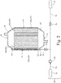
- FIG. 2 is a schematic diagram of hot layers (40a and 40b) in core 11 of heat exchanger 10.
- Heat exchanger 10 also includes tube inlet manifold 52, tube outlet manifold 54, heating fluid system 59, inlet manifold 61, and outlet manifold 63.
- Heating fluid system 59 includes first fluid supply line 60, second fluid supply line 62, temperature control valve 64, flow control valve 66, check valve 68, first fluid source 70, second fluid source 72, and regulated heating fluid line 74.
- Tube inlet manifold 52 is connected to tube 50 on third side 16.
- Tube outlet manifold 54 is connected to tube 50 on fourth side 18.
- Heating fluid passage 56 fluidically connects tube inlet manifold 52 and tube outlet manifold 54.
- tube inlet manifold 52 is configured to direct a heating fluid from regulated heating fluid line 74 into heating fluid passage 56.
- Tube outlet manifold 54 receives the heating fluid after the heating fluid traverses heating fluid passage 56.
- Heating fluid passage 56 is configured to contain and transport the heating fluid, which flows from inlet manifold 52 to outlet manifold 54 and transfers heat through tubes (50a or 50b) to inlets (22a or 22b) of cold layers (20a or 20b), respectively.
- Inlet manifold 61 of hot layers (40a or 40b) is on third side 16 and extends between first side 12 and second side 14. Inlet manifold 61 is configured to receive the hot fluid via an inlet of inlet manifold 61 (not shown) and direct the hot fluid into hot passages (46a and 46b). Outlet manifold 63 is on fourth side 18, opposite of inlet manifold 42, and extends between first side 12 and second side 14. Outlet manifold 63 is fluidically connected to inlet manifold 61 via hot passages (46a and 46b) of hot layers (40a and 40b). Outlet manifold 63 receives the hot fluid after the hot fluid traverses hot passages (46a and 46b) and directs the hot fluid to an outlet (not shown) on outlet manifold 63.
- Tubes (50a and 50b), tube inlet manifold 52, tube outlet manifold 54, first fluid supply line 60, second fluid supply line 62, temperature control valve 64, flow control valve 66, check valve 68, first fluid source 70, second fluid source 72, and regulated heating fluid line 74 are all fluidically connected.
- First fluid supply line 60 and second fluid supply line 62 carry fluids of different temperatures from first fluid source 70 and second fluid source 72 respectively.
- first fluid source 70 could be a hot fluid source, e.g., from a hot side of a turbine or any other hot components of an engine
- second fluid source 72 could be a cold fluid source, e.g., from a cold side of a ram air heat exchanger or any other cold components of the engine.
- first fluid source 70 could contain a cold fluid, e.g., from a cold side of a ram air heat exchanger or any other cold components of the engine
- second fluid source 72 could contain a hot fluid, e.g., from a hot side of a turbine or any other hot components of an engine.
- Temperature control valve 64 controls the quantity of fluid from first fluid supply line 60 and second fluid supply line 62 to control the temperature of the heating fluid (not shown) that flows through tubes (50a and 50b). After temperature control valve 64 determines the temperature of the heating fluid (not shown), flow control valve 66 determines the rate at which the heating fluid flows into regulated heating fluid line 74 and ultimately through tubes (50a and 50b). Temperature control valve 64 works in concert with flow control valve 66 to determine the melting capacity of the heating fluid (not shown) as it flows through tubes (50a and 50b). Check valve 68 prevents the heating fluid from flowing back into first fluid source 70, thereby preventing contamination of the system.
- a first fluid flows through first fluid supply line 60 and a second fluid (not shown) flows through second fluid supply line 62.
- Temperature control valve 64 determines the quantity of each the first fluid and the second fluid to control the heating fluid temperature.
- the fluid flows through flow control valve 66, which determines the quantity of the heating fluid that flows through tubes (50a and 50b). From flow control valve 66, the fluid flows through tube inlet manifold 52, tube 50, and out tube outlet manifold 54. While the heating fluid flows through tube 50, the heating fluid's heat is transferred through tube 50, thereby preventing or melting ice accretion on the above or below inlet 22 of cold layer 20.
- FIG. 2 shows an alternative design where inlet manifold 61 and tube inlet manifold 52 are one unitary, monolithic component and where outlet manifold 63 and tube outlet manifold 54 are one unitary, monolithic component.
- inlet manifold 61 and tube inlet manifold 52 are fluidically isolated from one another and outlet manifold 63 and tube outlet manifold 54 are fluidically isolated from one another.
- inlet manifold 61 and tube inlet manifold 52 are one unitary, monolithic component they can be additively manufactured.
- outlet manifold 63 and tube outlet manifold 54 are one unitary, monolithic component they can be additively manufactured.
- Core 11 is manufactured, as described above with FIG. 1 .
- the additively manufactured unitary, monolithic component including inlet manifold 61 and tube inlet manifold 52 can be attached to core 11 of heat exchanger 10 by welding, brazing, or any other method of mechanically coupling two metals.
- the additively manufactured unitary, monolithic component including outlet manifold 63 and tube outlet manifold 54 can be attached to core 11 of heat exchanger 10 by welding, brazing, or any other method of mechanically coupling two metals.
- FIG. 3 is schematic view of another example of hot layers (40a or 40b) of heat exchanger 10.
- Hot layers (40a or 40b) include fourth closure bar 49.
- fourth closure bar 49 is on first side 12 of heat exchanger 10 extending between third side 16 and fourth side 18.
- Tubes (50a or 50b) are attached to fourth closure bar 49.
- Tubes (50a or 50b) can be attached to fourth closure bar by welding, brazing, or any other way of mechanically coupling two metals.
- FIG. 3 shows an alternative design where inlet manifold 61 and tube inlet manifold 52 are each solitary components and where outlet manifold 63 and tube outlet manifold 54 are each solitary components.
- inlet manifold 61 and tube inlet manifold 52 are fluidically isolated from one another and outlet manifold 63 and tube outlet manifold 54 are fluidically isolated from one another.
- inlet manifold 61 and outlet manifold 63 are attached to core 11 and cold layers (20a and 20b) will likewise have an inlet manifold (not shown) and an outlet manifold (not shown) attached thereto.
- Tube inlet manifold 52 and tube outlet manifold 54 are attached to tubes (50a and 50b). Then, tube inlet manifold 52 is attached to heating fluid system 59 via regulated heating fluid line 74.
- a heat exchanger includes a first side opposite a second side and a third side opposite a fourth side. The third side and the fourth side extend from the first side to the second side.
- the heat exchanger also includes a cold layer with an inlet at the first side of the heat exchanger and an outlet at the second side of the heat exchanger.
- the cold layer also includes a cold passage extending from the inlet to the outlet.
- the heat exchanger also includes a hot layer with an inlet manifold at the third side of the heat exchanger extending between the first side and the second side and an outlet manifold at the fourth side of the heat exchanger opposite the inlet manifold and extending between the first side and the second side.
- the hot layer also includes a hot passage extending from the inlet manifold to the outlet manifold and a tube on the first side of the heat exchanger extending from the third side to the fourth side.
- the heat exchanger of the preceding paragraph can optionally include, additionally and/or alternatively, any one or more of the following features, configurations and/or additional components:
- a heat exchanger in another example, includes a first side opposite a second side and a third side opposite a fourth side, wherein the third side and the fourth side extend from the first side to the second side.
- the heat exchanger also includes a cold layer with a first closure bar on the third side extending from the first side to the second side, a second closure bar on the fourth side extending from the first side to the second side, and a cold passage between the first closure bar and the second closure bar, wherein the cold passage includes an inlet on the first side.
- the heat exchanger also includes a hot layer adjacent the cold layer.
- the hot layer includes a third closure bar on the second side extending from the third side to the fourth side, a closure tube on the first side extending from the third side to the fourth side.
- the closure tube includes a heating fluid passage extending from the third side to the fourth side.
- the hot layer also includes a hot passage between the third closure bar and the closure tube.
- the hot passage includes an inlet on the third side and an outlet on
- the heat exchanger of the preceding paragraph can optionally include, additionally and/or alternatively, any one or more of the following features, configurations and/or additional components:
- a method of preventing ice accretion on a cold inlet of a cold layer of a heat exchanger includes directing a cold flow through the cold inlet of the cold layer at a first side of the heat exchanger and out a cold outlet of the cold layer at a second side of the heat exchanger. The method also includes directing a hot flow through a hot inlet header of a hot layer at a third side of the heat exchanger and out the hot outlet header of the hot layer at the fourth side of the heat exchanger. The method also includes directing a heating fluid through a tube located on the first side of the heat exchanger. The heating fluid heats the cold inlet of the cold layer of the heat exchanger.
- the method of the preceding paragraph can optionally include, additionally and/or alternatively, any one or more of the following features, configurations and/or additional components: further comprising: controlling a temperature of the heating fluid via a temperature control valve, wherein the temperature control valve determines a quantity of a first fluid and a quantity of a second fluid that are mixed to form the heating fluid; and controlling heat transfer in the first side of the heat exchanger by controlling a flow of the heating fluid via a flow control valve between the tube and the temperature control valve.
Landscapes
- Engineering & Computer Science (AREA)
- Physics & Mathematics (AREA)
- Thermal Sciences (AREA)
- Mechanical Engineering (AREA)
- General Engineering & Computer Science (AREA)
- Heat-Exchange Devices With Radiators And Conduit Assemblies (AREA)
Abstract
Description
- The present disclosure relates to heat exchangers, and in particular to plate-fin crossflow heat exchangers.
- Heat exchangers are often used to transfer heat between two fluids. For example, in aircraft environmental control systems, heat exchangers may be used to transfer heat between a relatively hot air source (e.g., bleed air from a gas turbine engine) and a relatively cool air source (e.g., ram air). Some heat exchangers, often referred to as plate-fin heat exchangers, include a plate-fin core having multiple heat transfer sheets arranged in layers to define air passages there between. Closure bars seal alternating inlets of hot air and cool air inlet sides of the core. Accordingly, hot air and cool air are directed through alternating passages to form alternating layers of hot and cool air within the core. Heat is transferred between the hot and cool air via the heat transfer sheets that separate the layers. In addition, to facilitate heat transfer between the layers, each of the passages can include heat transfer fins, often formed of a material with high thermal conductivity (e.g., aluminum), that are oriented in the direction of the flow within the passage. The heat transfer fins increase turbulence and a surface area that is exposed to the airflow, thereby enhancing heat transfer between the layers.
- In some applications, heat exchangers can be exposed to extremely cold temperatures. When a heat exchanger is exposed to extremely cold temperatures ice accretion can occur. When there is ice accretion on a heat exchanger the ice accretion can result in restricting airflow into or out of the heat exchanger, thereby increasing the pressure loss across the heat exchanger and decreasing heat transfer performance.
- In one example, a heat exchanger includes a first side opposite a second side and a third side opposite a fourth side. The third side and the fourth side extend from the first side to the second side. The heat exchanger also includes a cold layer with an inlet at the first side of the heat exchanger and an outlet at the second side of the heat exchanger. The cold layer also includes a cold passage extending from the inlet to the outlet. The heat exchanger also includes a hot layer with an inlet manifold at the third side of the heat exchanger extending between the first side and the second side and an outlet manifold at the fourth side of the heat exchanger opposite the inlet manifold and extending between the first side and the second side. The hot layer also includes a hot passage extending from the inlet manifold to the outlet manifold and a tube on the first side of the heat exchanger extending from the third side to the fourth side.
- In another example, a heat exchanger includes a first side opposite a second side and a third side opposite a fourth side, wherein the third side and the fourth side extend from the first side to the second side. The heat exchanger also includes a cold layer with a first closure bar on the third side extending from the first side to the second side, a second closure bar on the fourth side extending from the first side to the second side, and a cold passage between the first closure bar and the second closure bar, wherein the cold passage includes an inlet on the first side. The heat exchanger also includes a hot layer adjacent the cold layer. The hot layer includes a third closure bar on the second side extending from the third side to the fourth side, a closure tube on the first side extending from the third side to the fourth side. The closure tube includes a heating fluid passage extending from the third side to the fourth side. The hot layer also includes a hot passage between the third closure bar and the closure tube. The hot passage includes an inlet on the third side and an outlet on the fourth side.
- In another example, a method of preventing ice accretion on a cold inlet of a cold layer of a heat exchanger includes directing a cold flow through the cold inlet of the cold layer at a first side of the heat exchanger and out a cold outlet of the cold layer at a second side of the heat exchanger. The method also includes directing a hot flow through a hot inlet header of a hot layer at a third side of the heat exchanger and out the hot outlet header of the hot layer at the fourth side of the heat exchanger. The method also includes directing a heating fluid through a tube located on the first side of the heat exchanger. The heating fluid heats the cold inlet of the cold layer of the heat exchanger.
-
-
FIG. 1 is a perspective view of a core of a heat exchanger. -
FIG. 2 is a schematic diagram of one example of a hot layer of the heat exchanger. -
FIG. 3 is a schematic diagram showing another example of the hot layer of the heat exchanger. - The present disclosure relates to a heat exchanger. The heat exchanger includes a cold layer and a hot layer. The hot layer includes a closure tube with a heating fluid passage configured to prevent ice accretion on the inlet of the cold layer. The heat exchanger will be described below with reference to
FIGS. 1-3 . -
FIG. 1 is a perspective view of an example of a core ofheat exchanger 10.Heat exchanger 10 includescore 11.Core 11 includesfirst side 12,second side 14,third side 16,fourth side 18, firstcold layer 20a, secondcold layer 20b, firsthot layer 40a, secondhot layer 40b, and parting sheets (43a, 43b, 43c, 43d, and 43e). Firstcold layer 20a includesinlet 22a,outlet 24a,first closure bar 26a,second closure bar 28a, a plurality of fins ("fins") 30a, andcold passages 32a. Firsthot layer 40a includes a plurality of fins ("fins") 45a,hot passages 46a,third closure bar 48a, closure tube (or tube) 50a. Tube 50a includesheating fluid passage 56a. Secondcold layer 20b includesinlet 22b,outlet 24b,first closure bar 26b,second closure bar 28b, a plurality of fins ("fins") 30b, andcold passages 32b. Secondhot layer 40b includes a plurality of fins ("fins") 45b,hot passages 46b,third closure bar 48b, closure tube (or tube) 50b. Tube 50b includesheating fluid passage 56b. - First
cold layer 20a is adjacent to firsthot layer 40a and firstcold layer 20a is separated from firsthot layer 40a byparting sheet 43b. Firsthot layer 40a is also adjacent to secondcold layer 20b and firsthot layer 40a is separated from secondcold layer 20b byparting sheet 43c. Secondcold layer 20b is also adjacent secondhot layer 40b. Secondcold layer 20b is separated from second hot layer byparting sheet 43d. Each of parting sheets (43b, 43c, and 43d) are configured to enable heat transfer between their contiguous and adjacent layers.Parting sheet 43a is adjacent to firstcold layer 20a opposite ofparting sheet 43b.Parting sheet 43e is adjacent to secondhot layer 40b opposite ofparting sheet 43d. - Inlets (22a and 22b) of cold layers (20a and 20b) are on
first side 12 and extend betweenthird side 16 andfourth side 18 ofcore 11 ofheat exchanger 10. Outlets (24a and 24b) of cold layers (20a and 20b) are onsecond side 14 and extend betweenthird side 16 andfourth side 18 ofheat exchanger 10. First closure bars (26a and 26b) are onthird side 16 and extend fromfirst side 12 tosecond side 14. Second closure bars (28a and 28b) are opposite first closure bars (26a and 26b) and are onfourth side 18 extending fromfirst side 12 tosecond side 14. Fins (30a and 30b) extend in cold layers (20a and 20b) betweenfirst end 12 andsecond end 14 and are spaced apart from each other betweenthird side 16 andfourth side 18.First closure bar 26a,second closure bar 28a,fins 30a,parting sheet 43a, andparting sheet 43b definecold passages 32a.First closure bar 26b,second closure bar 28b,fins 30b,parting sheet 43c, andparting sheet 43d definecold passages 32b. Cold passages (32a and 32b) extend betweenfirst side 12 andsecond side 14. - Third closure bars (48a and 48b) are on
second side 14 and extend betweenthird side 16 andfourth side 18.Third closure bar 48a is betweenparting sheet 43b andparting sheet 43c.Third closure bar 48b is betweenparting sheet 43d andparting sheet 43e. Tubes (50a and 50b) are onfirst side 12, opposite of third closure bars (48a and 48b), respectively, and extend betweenfirst side 12 andsecond side 14.Tube 50a is betweenparting sheet 43b andparting sheet 43c.Tube 50a functions as a closure bar for firsthot layer 40a.Tube 50b is betweenparting sheet 43d andparting sheet 43e.Tube 50b functions as a closure bar for secondhot layer 40b. Fins (45a and 45b) are spaced between third closure bar (48a and 48b) and tubes (50a and 50b), respectively, and extends betweenthird side 16 andfourth side 18.Third closure bar 48a,tube 50a,fins 45a, partingsheet 43b, andparting sheet 43c definehot passages 46a in firsthot layer 40a.Third closure bar 48b,tube 50b,fins 45b, partingsheet 43d, andparting sheet 43e definehot passages 46b in secondhot layer 40b. In the example shown inFIG. 1 , hot passages (46a and 48b) are configured to direct hot airflow fromthird side 16 tofourth side 18. In another example, hot passages (46a and 48b) can be configured to direct hot airflow fromfourth side 18 tothird side 16. All ofcore 11 ofheat exchanger 11 is made from material(s) with high thermal conductivity to encourage heat transfer between cold layers (20a and 20b) and hot layers (40a and 40b). - As shown in
FIG 1 , firsthot layer 40a can be stacked between firstcold layer 20a and secondcold layer 20b, and secondcold layer 20b can be stacked between firsthot layer 40a and secondhot layer 40b. In the example ofFIG 1 , tubes (50a and 50b) are configured to prevent ice accretion on inlets (22a and 22b) of firstcold layer 20a and secondcold layer 20b, respectively. In another example, the number of cold layers and the number of hot layers can be modified to adjust the heat transfer capabilities ofheat exchanger 10. -
Core 11 ofheat exchanger 10 is manufactured by stackingparting sheet 43a, firstcold layer 20a, partingsheet 43b, firsthot layer 40a, partingsheet 43c, secondcold layer 20b, partingsheet 43d, secondhot layer 40b, andparting sheet 43e, then brazing the layers together in a furnace. Firstcold layer 20a is made by placingfirst closure bar 26a onthird side 16 andsecond closure bar 28a onfourth side 18. Then,fins 30a are spaced apart from each other betweenfirst closure bar 26a andsecond closure bar 28a and extending betweenfirst side 12 andsecond side 14. Partingsheet 43b is then placed on top offirst closure bar 26a andsecond closure bar 28a to complete firstcold layer 20a. Next, firsthot layer 40a is made by placingthird closure bar 48a on top of partingsheet 43b onsecond side 14 and extending betweenthird side 16 andfourth side 18. Then,tube 50a is placed on top of partingsheet 43b opposite ofthird closure bar 48a onfirst side 12 extending betweenthird side 16 andfourth side 18.Fins 45a are then placed on top of partingsheet 43b, spaced from one another betweenthird closure bar 48a andtube 50a and extending betweenthird side 16 andfourth side 18. Partingsheet 43c is then placed atopthird closure bar 48a,tube 50a, andfins 45a to complete firsthot layer 40a. Secondcold layer 20b is made by placingfirst closure bar 26b onthird side 16 andsecond closure bar 28b onfourth side 18. Then,fins 30b are spaced apart from each other betweenfirst closure bar 26b andsecond closure bar 28b and extending betweenfirst side 12 andsecond side 14. Partingsheet 43d is then placed on top offirst closure bar 26b andsecond closure bar 28b to complete secondcold layer 20b. Next, secondhot layer 40b is made by placingthird closure bar 48b on top of partingsheet 43d onsecond side 14 and extending betweenthird side 16 andfourth side 18. Then,tube 50b is placed on top of partingsheet 43d opposite ofthird closure bar 48b onfirst side 12 extending betweenthird side 16 andfourth side 18.Fins 45b are then placed on top of partingsheet 43d, spaced from one another betweenthird closure bar 48b andtube 50b and extending betweenthird side 16 andfourth side 18. Partingsheet 43e is then placed atopthird closure bar 48a,tube 50a, andfins 45a to complete firsthot layer 40a.Core 11 is then loaded into a furnace with braze foil inserted into each of the joints ofcore 11 to brazecore 11 into one unitary, monolithic component. - Heating fluid passages (56a and 56b) are contained within tubes (50a and 50b), respectively, and extend between
third side 16 andfourth side 18. In the example shown inFIG. 1 , tubes (50a and 50b) are rectangular tubes. In another example, tubes (50a and 50b) can be cylindrical tubes, triangular tubes, or any other shape that fits between parting sheets (43b, 43c, 43d, and 43e) and accommodates heating fluid passages (56a and 56b). Heating fluid passages (56a and 56b) will be discussed in greater detail below with reference toFIGS. 2 and3 . -
FIG. 2 is a schematic diagram of hot layers (40a and 40b) incore 11 ofheat exchanger 10.Heat exchanger 10 also includestube inlet manifold 52,tube outlet manifold 54,heating fluid system 59,inlet manifold 61, andoutlet manifold 63.Heating fluid system 59 includes firstfluid supply line 60, secondfluid supply line 62,temperature control valve 64,flow control valve 66,check valve 68, firstfluid source 70, secondfluid source 72, and regulatedheating fluid line 74. -
Tube inlet manifold 52 is connected to tube 50 onthird side 16.Tube outlet manifold 54 is connected to tube 50 onfourth side 18.Heating fluid passage 56 fluidically connectstube inlet manifold 52 andtube outlet manifold 54.tube inlet manifold 52 is configured to direct a heating fluid from regulatedheating fluid line 74 intoheating fluid passage 56.Tube outlet manifold 54 receives the heating fluid after the heating fluid traversesheating fluid passage 56.Heating fluid passage 56 is configured to contain and transport the heating fluid, which flows frominlet manifold 52 tooutlet manifold 54 and transfers heat through tubes (50a or 50b) to inlets (22a or 22b) of cold layers (20a or 20b), respectively. -
Inlet manifold 61 of hot layers (40a or 40b) is onthird side 16 and extends betweenfirst side 12 andsecond side 14.Inlet manifold 61 is configured to receive the hot fluid via an inlet of inlet manifold 61 (not shown) and direct the hot fluid into hot passages (46a and 46b).Outlet manifold 63 is onfourth side 18, opposite of inlet manifold 42, and extends betweenfirst side 12 andsecond side 14.Outlet manifold 63 is fluidically connected toinlet manifold 61 via hot passages (46a and 46b) of hot layers (40a and 40b).Outlet manifold 63 receives the hot fluid after the hot fluid traverses hot passages (46a and 46b) and directs the hot fluid to an outlet (not shown) onoutlet manifold 63. - Tubes (50a and 50b),
tube inlet manifold 52,tube outlet manifold 54, firstfluid supply line 60, secondfluid supply line 62,temperature control valve 64,flow control valve 66,check valve 68, firstfluid source 70, secondfluid source 72, and regulatedheating fluid line 74 are all fluidically connected. Firstfluid supply line 60 and secondfluid supply line 62 carry fluids of different temperatures from firstfluid source 70 and secondfluid source 72 respectively. For instance, in one example firstfluid source 70 could be a hot fluid source, e.g., from a hot side of a turbine or any other hot components of an engine, and secondfluid source 72 could be a cold fluid source, e.g., from a cold side of a ram air heat exchanger or any other cold components of the engine. In another example, firstfluid source 70 could contain a cold fluid, e.g., from a cold side of a ram air heat exchanger or any other cold components of the engine, and secondfluid source 72 could contain a hot fluid, e.g., from a hot side of a turbine or any other hot components of an engine. -
Temperature control valve 64 controls the quantity of fluid from firstfluid supply line 60 and secondfluid supply line 62 to control the temperature of the heating fluid (not shown) that flows through tubes (50a and 50b). Aftertemperature control valve 64 determines the temperature of the heating fluid (not shown),flow control valve 66 determines the rate at which the heating fluid flows into regulatedheating fluid line 74 and ultimately through tubes (50a and 50b).Temperature control valve 64 works in concert withflow control valve 66 to determine the melting capacity of the heating fluid (not shown) as it flows through tubes (50a and 50b). Checkvalve 68 prevents the heating fluid from flowing back into firstfluid source 70, thereby preventing contamination of the system. - In operation a first fluid (not shown) flows through first
fluid supply line 60 and a second fluid (not shown) flows through secondfluid supply line 62.Temperature control valve 64 determines the quantity of each the first fluid and the second fluid to control the heating fluid temperature. The fluid flows throughflow control valve 66, which determines the quantity of the heating fluid that flows through tubes (50a and 50b). Fromflow control valve 66, the fluid flows throughtube inlet manifold 52, tube 50, and outtube outlet manifold 54. While the heating fluid flows through tube 50, the heating fluid's heat is transferred through tube 50, thereby preventing or melting ice accretion on the above or below inlet 22 of cold layer 20. -
FIG. 2 shows an alternative design whereinlet manifold 61 andtube inlet manifold 52 are one unitary, monolithic component and whereoutlet manifold 63 andtube outlet manifold 54 are one unitary, monolithic component. In each of the above examples,inlet manifold 61 andtube inlet manifold 52 are fluidically isolated from one another andoutlet manifold 63 andtube outlet manifold 54 are fluidically isolated from one another. Wheninlet manifold 61 andtube inlet manifold 52 are one unitary, monolithic component they can be additively manufactured. Likewise, whenoutlet manifold 63 andtube outlet manifold 54 are one unitary, monolithic component they can be additively manufactured.Core 11 is manufactured, as described above withFIG. 1 . Then, the additively manufactured unitary, monolithic component includinginlet manifold 61 andtube inlet manifold 52 can be attached tocore 11 ofheat exchanger 10 by welding, brazing, or any other method of mechanically coupling two metals. Similarly, the additively manufactured unitary, monolithic component includingoutlet manifold 63 andtube outlet manifold 54 can be attached tocore 11 ofheat exchanger 10 by welding, brazing, or any other method of mechanically coupling two metals. -
FIG. 3 is schematic view of another example of hot layers (40a or 40b) ofheat exchanger 10. Hot layers (40a or 40b) includefourth closure bar 49. In the example shown inFIG. 3 ,fourth closure bar 49 is onfirst side 12 ofheat exchanger 10 extending betweenthird side 16 andfourth side 18. Tubes (50a or 50b) are attached tofourth closure bar 49. Tubes (50a or 50b) can be attached to fourth closure bar by welding, brazing, or any other way of mechanically coupling two metals. - The example shown in
FIG. 3 shows an alternative design whereinlet manifold 61 andtube inlet manifold 52 are each solitary components and whereoutlet manifold 63 andtube outlet manifold 54 are each solitary components. In the above examples,inlet manifold 61 andtube inlet manifold 52 are fluidically isolated from one another andoutlet manifold 63 andtube outlet manifold 54 are fluidically isolated from one another. - After
core 11 is manufactured, as described above withFIG. 1 ,inlet manifold 61 andoutlet manifold 63 are attached tocore 11 and cold layers (20a and 20b) will likewise have an inlet manifold (not shown) and an outlet manifold (not shown) attached thereto.Tube inlet manifold 52 andtube outlet manifold 54 are attached to tubes (50a and 50b). Then,tube inlet manifold 52 is attached toheating fluid system 59 via regulatedheating fluid line 74. - The following are non-exclusive descriptions of possible embodiments of the present invention.
- A heat exchanger includes a first side opposite a second side and a third side opposite a fourth side. The third side and the fourth side extend from the first side to the second side. The heat exchanger also includes a cold layer with an inlet at the first side of the heat exchanger and an outlet at the second side of the heat exchanger. The cold layer also includes a cold passage extending from the inlet to the outlet. The heat exchanger also includes a hot layer with an inlet manifold at the third side of the heat exchanger extending between the first side and the second side and an outlet manifold at the fourth side of the heat exchanger opposite the inlet manifold and extending between the first side and the second side. The hot layer also includes a hot passage extending from the inlet manifold to the outlet manifold and a tube on the first side of the heat exchanger extending from the third side to the fourth side.
- The heat exchanger of the preceding paragraph can optionally include, additionally and/or alternatively, any one or more of the following features, configurations and/or additional components:
- wherein the cold layer further comprises: a first closure bar on the third side extending from the first side to the second side; a second closure bar on the fourth side extending from the first side to the second side; a plurality of fins between the first closure bar and the second closure bar extending from the first side to the second side; and a plurality of cold passages defined by the first closure bar, the second closure bar, and the plurality of fins of the cold layer;
- wherein the hot layer further comprises: a third closure bar on the second side of the heat exchanger extending from the third side to the fourth side; a plurality of fins between the tube and the third closure bar extending from the third side to the fourth side; a plurality of passages defined by the tube, the third closure bar, and the plurality of fins of the hot layer;
- further comprising: a second cold layer; and a second hot layer, wherein: the second cold layer is stacked between the hot layer and the second hot layer; the second hot layer is stacked between the cold layer and the second cold layer; and the second hot layer comprises a second tube on the first side of the heat exchanger and extending from the third side to the fourth side;
- further comprising: a first fluid supply line configured to contain a first fluid; a second fluid supply line configured to contain a second fluid; and a control valve, wherein the control valve is fluidically connected to the first fluid supply line and the second fluid supply line, and wherein the control valve determines a quantity of the first fluid and quantity of the second fluid that flows into the tube of the hot layer and the tube of the second hot layer;
- wherein the tube of the hot layer comprises: a tube inlet manifold on the third side of the heat exchanger; and a tube outlet manifold on the fourth side of the heat exchanger, wherein the tube of the hot layer fluidically connects the tube inlet manifold and the tube outlet manifold;
- wherein the tube inlet manifold and the inlet manifold of the hot layer are a unitary, monolithic component, and wherein the tube inlet manifold and the inlet manifold of the hot layer are additively manufactured;
- wherein the tube outlet manifold and the outlet manifold of the hot layer are one unitary, monolithic component, and wherein the tube outlet manifold and the outlet manifold of the hot layer are additively manufactured;
- wherein the hot layer further comprises: a third closure bar on the second side of the heat exchanger extending from the third side to the fourth side; a fourth closure bar on the first side of the heat exchanger extending from the third side to the fourth side, wherein the tube is attached to the fourth closure bar; a plurality of fins between the third closure bar and the fourth closure bar extending from the third side to the fourth side; and a plurality of passages defined by the third closure bar, the fourth closure bar, and the plurality of fins of the hot layer extending from the third side to the fourth side;
- further comprising: a first fluid supply line configured to contain a first fluid; a second fluid supply li ne configured to contain a second fluid; and a control valve, wherein the control valve is fluidically connected to the first fluid supply line and the second fluid supply line, and wherein the control valve determines a quantity of the first fluid and a quantity of the second fluid that flows into he tube of the hot layer;
- wherein the tube of the hot layer comprises: a tube inlet manifold on the third side of the heat exchanger; and a tube outlet manifold on the fourth side of the heat exchanger, wherein the tube of the hot layer fluidically connects the tube inlet manifold and the tube outlet manifold;
- wherein the tube inlet manifold and the inlet manifold of the hot layer are a unitary, monolithic component, and wherein the tube inlet manifold and the inlet manifold of the hot layer are additively manufactured; and
- wherein the tube outlet manifold and the outlet manifold of the hot layer are one unitary, monolithic component, and wherein the tube outlet manifold and the outlet manifold of the hot layer are additively manufactured.
- In another example, a heat exchanger includes a first side opposite a second side and a third side opposite a fourth side, wherein the third side and the fourth side extend from the first side to the second side. The heat exchanger also includes a cold layer with a first closure bar on the third side extending from the first side to the second side, a second closure bar on the fourth side extending from the first side to the second side, and a cold passage between the first closure bar and the second closure bar, wherein the cold passage includes an inlet on the first side. The heat exchanger also includes a hot layer adjacent the cold layer. The hot layer includes a third closure bar on the second side extending from the third side to the fourth side, a closure tube on the first side extending from the third side to the fourth side. The closure tube includes a heating fluid passage extending from the third side to the fourth side. The hot layer also includes a hot passage between the third closure bar and the closure tube. The hot passage includes an inlet on the third side and an outlet on the fourth side.
- The heat exchanger of the preceding paragraph can optionally include, additionally and/or alternatively, any one or more of the following features, configurations and/or additional components:
- wherein the heat exchanger further comprises: an inlet manifold on the third side of the heat exchanger; and an outlet manifold on the fourth side of the heat exchanger, wherein the closure tube fluidically connects the inlet manifold and the outlet manifold;
- wherein the hot layer further comprises: an inlet manifold on the third side; and an outlet manifold on the fourth side, wherein the inlet manifold and the outlet manifold extend between the first side and the second side;
- wherein the inlet manifold of the hot layer and the inlet manifold of the closure tube are one unitary, monolithic component, and wherein the inlet manifold of the hot layer and the inlet manifold of the closure tube are additively manufactured; and
- wherein the outlet manifold of the hot layer and the outlet manifold of the closure tube are one unitary, monolithic component, and wherein the outlet manifold of the hot layer and the outlet manifold of the closure tube are additively manufactured.
- In another example, a method of preventing ice accretion on a cold inlet of a cold layer of a heat exchanger includes directing a cold flow through the cold inlet of the cold layer at a first side of the heat exchanger and out a cold outlet of the cold layer at a second side of the heat exchanger. The method also includes directing a hot flow through a hot inlet header of a hot layer at a third side of the heat exchanger and out the hot outlet header of the hot layer at the fourth side of the heat exchanger. The method also includes directing a heating fluid through a tube located on the first side of the heat exchanger. The heating fluid heats the cold inlet of the cold layer of the heat exchanger.
- The method of the preceding paragraph can optionally include, additionally and/or alternatively, any one or more of the following features, configurations and/or additional components:
further comprising: controlling a temperature of the heating fluid via a temperature control valve, wherein the temperature control valve determines a quantity of a first fluid and a quantity of a second fluid that are mixed to form the heating fluid; and controlling heat transfer in the first side of the heat exchanger by controlling a flow of the heating fluid via a flow control valve between the tube and the temperature control valve. - While the invention has been described with reference to an exemplary embodiment(s), it will be understood by those skilled in the art that various changes may be made without departing from the scope of the invention as defined by the claims. In addition, many modifications may be made to adapt a particular situation or material to the teachings of the invention without departing from the scope of the claims. Therefore, it is intended that the invention not be limited to the particular embodiment(s) disclosed, but that the invention will include all embodiments falling within the scope of the appended claims.
Claims (15)
- A heat exchanger comprising:a first side (12) opposite a second side (14);a third side (16) opposite a fourth side (18), wherein the third side and the fourth side extend from the first side to the second side;a cold layer (20a) comprising:an inlet (22a) at the first side of the heat exchanger;an outlet (24a) at the second side of the heat exchanger; anda cold passage (32a) extending from the inlet to the outlet; anda hot layer (40a) comprising:an inlet manifold (61) at the third side of the heat exchanger extending between the first side and the second side;an outlet manifold (63) at the fourth side of the heat exchanger opposite the inlet manifold and extending between the first side and the second side;a hot passage (46a) extending from the inlet manifold to the outlet manifold; anda tube (50a) on the first side of the heat exchanger extending from the third side to the fourth side.
- The heat exchanger of claim 1, wherein the cold layer further comprises:a first closure bar (26a) on the third side extending from the first side to the second side;a second closure bar (28a) on the fourth side extending from the first side to the second side;a plurality of fins (30a) between the first closure bar and the second closure bar extending from the first side to the second side; anda plurality of cold passages (32a) defined by the first closure bar, the second closure bar, and the plurality of fins of the cold layer.
- The heat exchanger of claim 2, wherein the hot layer further comprises:a third closure bar (48a) on the second side of the heat exchanger extending from the third side to the fourth side;a plurality of fins (45a) between the tube and the third closure bar extending from the third side to the fourth side;a plurality of passages (46a) defined by the tube, the third closure bar, and the plurality of fins of the hot layer.
- The heat exchanger of claim 3 further comprising:a second cold layer (20b); anda second hot layer (40b),wherein:the second cold layer is stacked between the hot layer and the second hot layer;the second hot layer is stacked between the cold layer and the second cold layer; andthe second hot layer comprises a second tube on the first side of the heat exchanger and extending from the third side to the fourth side.
- The heat exchanger of claim 4, further comprising:a first fluid supply line (60) configured to contain a first fluid;a second fluid supply line (62) configured to contain a second fluid; anda control valve (66), wherein the control valve is fluidically connected to the first fluid supply line and the second fluid supply line, and wherein the control valve determines a quantity of the first fluid and a quantity of the second fluid that flows into the tube of the hot layer and the tube of the second hot layer.
- The heat exchanger of claim 5, wherein the tube of the hot layer comprises:a tube inlet manifold (52) on the third side of the heat exchanger; anda tube outlet manifold (54) on the fourth side of the heat exchanger, wherein the tube of the hot layer fluidically connects the tube inlet manifold and the tube outlet manifold.
- The heat exchanger of claim 6, wherein the tube inlet manifold (52) and the inlet manifold (61) of the hot layer are a unitary, monolithic component, and wherein the tube inlet manifold and the inlet manifold of the hot layer are additively manufactured.
- The heat exchanger of claim 6 or 7, wherein the tube outlet manifold (54) and the outlet manifold (63) of the hot layer are one unitary, monolithic component, and wherein the tube outlet manifold and the outlet manifold of the hot layer are additively manufactured.
- The heat exchanger of claim 2, wherein the hot layer further comprises:a third closure bar (48) on the second side of the heat exchanger extending from the third side to the fourth side;a fourth closure bar (49) on the first side of the heat exchanger extending from the third side to the fourth side, wherein the tube is attached to the fourth closure bar;a plurality of fins (45) between the third closure bar and the fourth closure bar extending from the third side to the fourth side; anda plurality of passages (46) defined by the third closure bar, the fourth closure bar, and the plurality of fins of the hot layer extending from the third side to the fourth side.
- The heat exchanger of claim 9, further comprising:a first fluid supply line (60) configured to contain a first fluid;a second fluid supply line (62) configured to contain a second fluid; anda control valve (66), wherein the control valve is fluidically connected to the first fluid supply line and the second fluid supply line, and wherein the control valve determines a quantity of the first fluid and a quantity of the second fluid that flows into the tube of the hot layer.
- The heat exchanger of claim 9, wherein the tube of the hot layer comprises:a tube inlet manifold (52) on the third side of the heat exchanger; anda tube outlet manifold (54) on the fourth side of the heat exchanger, wherein the tube of the hot layer fluidically connects the tube inlet manifold and the tube outlet manifold.
- The heat exchanger of claim 11, wherein the tube inlet manifold and the inlet manifold of the hot layer are a unitary, monolithic component, and wherein the tube inlet manifold and the inlet manifold of the hot layer are additively manufactured.
- The heat exchanger of claim 11, wherein the tube outlet manifold and the outlet manifold of the hot layer are one unitary, monolithic component, and wherein the tube outlet manifold and the outlet manifold of the hot layer are additively manufactured.
- A method of preventing ice accretion on an inlet of a cold layer of a heat exchanger comprising:directing a cold flow through the inlet of the cold layer at a first side of the heat exchanger and out an outlet of the cold layer at a second side of the heat exchanger;directing a hot flow through an inlet header of a hot layer at a third side of the heat exchanger and out the outlet header of the hot layer at a fourth side of the heat exchanger; anddirecting a heating fluid through a tube located on the first side of the heat exchanger, wherein the heating fluid heats the inlet of the cold layer of the heat exchanger.
- The method of claim 14, further comprising:controlling a temperature of the heating fluid via a temperature control valve, wherein the temperature control valve determines a quantity of a first fluid and a quantity of a second fluid that are mixed to form the heating fluid; and controlling heat transfer in the first side of the heat exchanger by controlling a flow of the heating fluid via a flow control valve between the tube and the temperature control valve.
Applications Claiming Priority (1)
| Application Number | Priority Date | Filing Date | Title |
|---|---|---|---|
| US17/112,087 US11668531B2 (en) | 2020-12-04 | 2020-12-04 | Subfreezing heat exchanger with separate melt fluid |
Publications (2)
| Publication Number | Publication Date |
|---|---|
| EP4008985A1 true EP4008985A1 (en) | 2022-06-08 |
| EP4008985B1 EP4008985B1 (en) | 2026-04-08 |
Family
ID=78821606
Family Applications (1)
| Application Number | Title | Priority Date | Filing Date |
|---|---|---|---|
| EP21212244.4A Active EP4008985B1 (en) | 2020-12-04 | 2021-12-03 | Subfreezing heat exchanger with separate melt fluid |
Country Status (2)
| Country | Link |
|---|---|
| US (1) | US11668531B2 (en) |
| EP (1) | EP4008985B1 (en) |
Families Citing this family (1)
| Publication number | Priority date | Publication date | Assignee | Title |
|---|---|---|---|---|
| KR102899810B1 (en) * | 2023-03-27 | 2025-12-12 | 한국기계연구원 | Heat exchanger with freeze protection |
Citations (4)
| Publication number | Priority date | Publication date | Assignee | Title |
|---|---|---|---|---|
| US4246963A (en) * | 1978-10-26 | 1981-01-27 | The Garrett Corporation | Heat exchanger |
| EP0019492B1 (en) * | 1979-05-22 | 1986-04-09 | The Garrett Corporation | Gas conditioning system, especially air conditioning system |
| US6460353B2 (en) * | 2001-03-02 | 2002-10-08 | Honeywell International Inc. | Method and apparatus for improved aircraft environmental control system utilizing parallel heat exchanger arrays |
| US20130061617A1 (en) * | 2011-09-13 | 2013-03-14 | Honeywell International Inc. | Air cycle condenser cold inlet heating using internally finned hot bars |
Family Cites Families (8)
| Publication number | Priority date | Publication date | Assignee | Title |
|---|---|---|---|---|
| US3196942A (en) * | 1963-07-05 | 1965-07-27 | United Aircraft Corp | Heat exchanger construction including tubular closure plates |
| US3601185A (en) * | 1969-11-04 | 1971-08-24 | United Aircraft Corp | Heat exchanger construction |
| US4862952A (en) * | 1988-05-09 | 1989-09-05 | United Technologies Corporation | Frost free heat exchanger |
| IT1224459B (en) * | 1988-09-30 | 1990-10-04 | Fiat Auto Spa | INTEGRATED WATER OIL RADIATOR IN PARTICULAR FOR VEHICLES |
| US8276654B2 (en) | 2005-11-17 | 2012-10-02 | Hamilton Sundstrand Corporation | Core assembly with deformation preventing features |
| KR101344514B1 (en) * | 2007-06-20 | 2013-12-24 | 한라비스테온공조 주식회사 | A Cooling System for a Vehicle |
| DE102014001575A1 (en) * | 2013-03-27 | 2014-10-02 | Modine Manufacturing Co. | Air-air heat exchanger |
| US10995997B2 (en) * | 2018-06-26 | 2021-05-04 | Hamilton Sunstrand Corporation | Heat exchanger with integral features |
-
2020
- 2020-12-04 US US17/112,087 patent/US11668531B2/en active Active
-
2021
- 2021-12-03 EP EP21212244.4A patent/EP4008985B1/en active Active
Patent Citations (4)
| Publication number | Priority date | Publication date | Assignee | Title |
|---|---|---|---|---|
| US4246963A (en) * | 1978-10-26 | 1981-01-27 | The Garrett Corporation | Heat exchanger |
| EP0019492B1 (en) * | 1979-05-22 | 1986-04-09 | The Garrett Corporation | Gas conditioning system, especially air conditioning system |
| US6460353B2 (en) * | 2001-03-02 | 2002-10-08 | Honeywell International Inc. | Method and apparatus for improved aircraft environmental control system utilizing parallel heat exchanger arrays |
| US20130061617A1 (en) * | 2011-09-13 | 2013-03-14 | Honeywell International Inc. | Air cycle condenser cold inlet heating using internally finned hot bars |
Also Published As
| Publication number | Publication date |
|---|---|
| US20220178621A1 (en) | 2022-06-09 |
| US11668531B2 (en) | 2023-06-06 |
| EP4008985B1 (en) | 2026-04-08 |
Similar Documents
| Publication | Publication Date | Title |
|---|---|---|
| US8708036B2 (en) | Heat exchanger for cooling high-temperature gas | |
| EP3258204A1 (en) | Header for a heat exchanger | |
| US10316750B2 (en) | Single phase micro/mini channel heat exchangers for gas turbine intercooling | |
| EP1714100B1 (en) | Method of forming a brazed plate fin heat exchanger | |
| EP3553446B1 (en) | Shaped leading edge of cast plate fin heat exchanger | |
| EP3196584B1 (en) | Heat exchanger with adjacent inlets and outlets | |
| US20160161189A1 (en) | Plate-fin tubular hybrid heat exchanger design for an air and fuel cooled air cooler | |
| US3528496A (en) | Plate-fin heat exchanger | |
| US20210231381A1 (en) | Fractal heat exchanger with bypass | |
| GB2036286A (en) | Heat exchangers | |
| EP3734212B1 (en) | Asymmetric cross counter flow heat exchanger | |
| EP4008985B1 (en) | Subfreezing heat exchanger with separate melt fluid | |
| EP2977703B1 (en) | Heat exchanger with slotted guard fin | |
| EP3176533A1 (en) | Cross flow ceramic heat exchanger and method for manufacturing | |
| EP3734213B1 (en) | Offset/slanted cross counter flow heat exchanger | |
| US20090288811A1 (en) | Aluminum plate-fin heat exchanger utilizing titanium separator plates | |
| EP3196581B1 (en) | Heat exchanger with center manifold and thermal separator | |
| EP3473961B1 (en) | Heat exchanger | |
| EP3553448B1 (en) | Secondarily applied cold side features for cast heat exchanger | |
| EP3043138B1 (en) | Heat exchanger with fin wave control | |
| EP3106824A1 (en) | Mini-channel heat exchanger tube sleeve | |
| EP4498030A1 (en) | Heat exchanger | |
| US20210033352A1 (en) | Plate fin crossflow heat exchanger | |
| EP4083564A1 (en) | Heated header for subfreezing heat exchanger | |
| EP3904810B1 (en) | Crossflow/counterflow subfreezing plate fin heat exchanger |
Legal Events
| Date | Code | Title | Description |
|---|---|---|---|
| PUAI | Public reference made under article 153(3) epc to a published international application that has entered the european phase |
Free format text: ORIGINAL CODE: 0009012 |
|
| STAA | Information on the status of an ep patent application or granted ep patent |
Free format text: STATUS: THE APPLICATION HAS BEEN PUBLISHED |
|
| AK | Designated contracting states |
Kind code of ref document: A1 Designated state(s): AL AT BE BG CH CY CZ DE DK EE ES FI FR GB GR HR HU IE IS IT LI LT LU LV MC MK MT NL NO PL PT RO RS SE SI SK SM TR |
|
| STAA | Information on the status of an ep patent application or granted ep patent |
Free format text: STATUS: REQUEST FOR EXAMINATION WAS MADE |
|
| 17P | Request for examination filed |
Effective date: 20221206 |
|
| RBV | Designated contracting states (corrected) |
Designated state(s): AL AT BE BG CH CY CZ DE DK EE ES FI FR GB GR HR HU IE IS IT LI LT LU LV MC MK MT NL NO PL PT RO RS SE SI SK SM TR |
|
| GRAP | Despatch of communication of intention to grant a patent |
Free format text: ORIGINAL CODE: EPIDOSNIGR1 |
|
| STAA | Information on the status of an ep patent application or granted ep patent |
Free format text: STATUS: GRANT OF PATENT IS INTENDED |
|
| INTG | Intention to grant announced |
Effective date: 20251204 |
|
| GRAS | Grant fee paid |
Free format text: ORIGINAL CODE: EPIDOSNIGR3 |
|
| GRAA | (expected) grant |
Free format text: ORIGINAL CODE: 0009210 |
|
| STAA | Information on the status of an ep patent application or granted ep patent |
Free format text: STATUS: THE PATENT HAS BEEN GRANTED |
|
| AK | Designated contracting states |
Kind code of ref document: B1 Designated state(s): AL AT BE BG CH CY CZ DE DK EE ES FI FR GB GR HR HU IE IS IT LI LT LU LV MC MK MT NL NO PL PT RO RS SE SI SK SM TR |
|
| REG | Reference to a national code |
Ref country code: CH Ref legal event code: F10 Free format text: ST27 STATUS EVENT CODE: U-0-0-F10-F00 (AS PROVIDED BY THE NATIONAL OFFICE) Effective date: 20260408 Ref country code: GB Ref legal event code: FG4D |
|
| REG | Reference to a national code |
Ref country code: DE Ref legal event code: R096 Ref document number: 602021051539 Country of ref document: DE |