EP4008972A1 - A method and a system for operating an air handling unit at effective static pressure - Google Patents
A method and a system for operating an air handling unit at effective static pressure Download PDFInfo
- Publication number
- EP4008972A1 EP4008972A1 EP21212494.5A EP21212494A EP4008972A1 EP 4008972 A1 EP4008972 A1 EP 4008972A1 EP 21212494 A EP21212494 A EP 21212494A EP 4008972 A1 EP4008972 A1 EP 4008972A1
- Authority
- EP
- European Patent Office
- Prior art keywords
- ahu
- static pressure
- setpoint
- vav
- airflow
- Prior art date
- Legal status (The legal status is an assumption and is not a legal conclusion. Google has not performed a legal analysis and makes no representation as to the accuracy of the status listed.)
- Pending
Links
- 230000003068 static effect Effects 0.000 title claims abstract description 103
- 238000000034 method Methods 0.000 title claims abstract description 32
- 230000000694 effects Effects 0.000 claims abstract description 24
- 235000003642 hunger Nutrition 0.000 claims description 33
- 238000012544 monitoring process Methods 0.000 claims description 9
- 230000003247 decreasing effect Effects 0.000 claims description 5
- 238000011217 control strategy Methods 0.000 claims description 3
- PJDQVZSBWDEYOF-APQOSEDMSA-N 1-[(3s,5s,6r)-5-hydroxy-6-(hydroxymethyl)oxan-3-yl]-5-iodopyrimidine-2,4-dione Chemical compound C1[C@H](O)[C@@H](CO)OC[C@H]1N1C(=O)NC(=O)C(I)=C1 PJDQVZSBWDEYOF-APQOSEDMSA-N 0.000 claims 10
- 238000010438 heat treatment Methods 0.000 description 11
- 238000001816 cooling Methods 0.000 description 10
- 238000010586 diagram Methods 0.000 description 4
- 238000009434 installation Methods 0.000 description 4
- 241000743339 Agrostis Species 0.000 description 2
- 238000004378 air conditioning Methods 0.000 description 2
- 238000010276 construction Methods 0.000 description 2
- 238000005516 engineering process Methods 0.000 description 2
- 230000004048 modification Effects 0.000 description 2
- 238000012986 modification Methods 0.000 description 2
- 230000037351 starvation Effects 0.000 description 2
- 238000009423 ventilation Methods 0.000 description 2
- 230000004075 alteration Effects 0.000 description 1
- 238000012550 audit Methods 0.000 description 1
- 230000008859 change Effects 0.000 description 1
- 230000001143 conditioned effect Effects 0.000 description 1
- 230000007547 defect Effects 0.000 description 1
- 230000006870 function Effects 0.000 description 1
- 230000007246 mechanism Effects 0.000 description 1
- 230000008569 process Effects 0.000 description 1
- 239000002096 quantum dot Substances 0.000 description 1
- XLYOFNOQVPJJNP-UHFFFAOYSA-N water Substances O XLYOFNOQVPJJNP-UHFFFAOYSA-N 0.000 description 1
Images


Classifications
-
- F—MECHANICAL ENGINEERING; LIGHTING; HEATING; WEAPONS; BLASTING
- F24—HEATING; RANGES; VENTILATING
- F24F—AIR-CONDITIONING; AIR-HUMIDIFICATION; VENTILATION; USE OF AIR CURRENTS FOR SCREENING
- F24F11/00—Control or safety arrangements
- F24F11/70—Control systems characterised by their outputs; Constructional details thereof
- F24F11/72—Control systems characterised by their outputs; Constructional details thereof for controlling the supply of treated air, e.g. its pressure
- F24F11/74—Control systems characterised by their outputs; Constructional details thereof for controlling the supply of treated air, e.g. its pressure for controlling air flow rate or air velocity
- F24F11/77—Control systems characterised by their outputs; Constructional details thereof for controlling the supply of treated air, e.g. its pressure for controlling air flow rate or air velocity by controlling the speed of ventilators
-
- F—MECHANICAL ENGINEERING; LIGHTING; HEATING; WEAPONS; BLASTING
- F24—HEATING; RANGES; VENTILATING
- F24F—AIR-CONDITIONING; AIR-HUMIDIFICATION; VENTILATION; USE OF AIR CURRENTS FOR SCREENING
- F24F11/00—Control or safety arrangements
- F24F11/30—Control or safety arrangements for purposes related to the operation of the system, e.g. for safety or monitoring
- F24F11/46—Improving electric energy efficiency or saving
-
- F—MECHANICAL ENGINEERING; LIGHTING; HEATING; WEAPONS; BLASTING
- F24—HEATING; RANGES; VENTILATING
- F24F—AIR-CONDITIONING; AIR-HUMIDIFICATION; VENTILATION; USE OF AIR CURRENTS FOR SCREENING
- F24F11/00—Control or safety arrangements
- F24F11/62—Control or safety arrangements characterised by the type of control or by internal processing, e.g. using fuzzy logic, adaptive control or estimation of values
- F24F11/63—Electronic processing
- F24F11/64—Electronic processing using pre-stored data
-
- F—MECHANICAL ENGINEERING; LIGHTING; HEATING; WEAPONS; BLASTING
- F24—HEATING; RANGES; VENTILATING
- F24F—AIR-CONDITIONING; AIR-HUMIDIFICATION; VENTILATION; USE OF AIR CURRENTS FOR SCREENING
- F24F11/00—Control or safety arrangements
- F24F11/70—Control systems characterised by their outputs; Constructional details thereof
- F24F11/72—Control systems characterised by their outputs; Constructional details thereof for controlling the supply of treated air, e.g. its pressure
- F24F11/74—Control systems characterised by their outputs; Constructional details thereof for controlling the supply of treated air, e.g. its pressure for controlling air flow rate or air velocity
-
- F—MECHANICAL ENGINEERING; LIGHTING; HEATING; WEAPONS; BLASTING
- F24—HEATING; RANGES; VENTILATING
- F24F—AIR-CONDITIONING; AIR-HUMIDIFICATION; VENTILATION; USE OF AIR CURRENTS FOR SCREENING
- F24F3/00—Air-conditioning systems in which conditioned primary air is supplied from one or more central stations to distributing units in the rooms or spaces where it may receive secondary treatment; Apparatus specially designed for such systems
- F24F3/001—Air-conditioning systems in which conditioned primary air is supplied from one or more central stations to distributing units in the rooms or spaces where it may receive secondary treatment; Apparatus specially designed for such systems in which the air treatment in the central station takes place by means of a heat-pump or by means of a reversible cycle
-
- F—MECHANICAL ENGINEERING; LIGHTING; HEATING; WEAPONS; BLASTING
- F24—HEATING; RANGES; VENTILATING
- F24F—AIR-CONDITIONING; AIR-HUMIDIFICATION; VENTILATION; USE OF AIR CURRENTS FOR SCREENING
- F24F2110/00—Control inputs relating to air properties
- F24F2110/30—Velocity
-
- F—MECHANICAL ENGINEERING; LIGHTING; HEATING; WEAPONS; BLASTING
- F24—HEATING; RANGES; VENTILATING
- F24F—AIR-CONDITIONING; AIR-HUMIDIFICATION; VENTILATION; USE OF AIR CURRENTS FOR SCREENING
- F24F2110/00—Control inputs relating to air properties
- F24F2110/40—Pressure, e.g. wind pressure
-
- F—MECHANICAL ENGINEERING; LIGHTING; HEATING; WEAPONS; BLASTING
- F24—HEATING; RANGES; VENTILATING
- F24F—AIR-CONDITIONING; AIR-HUMIDIFICATION; VENTILATION; USE OF AIR CURRENTS FOR SCREENING
- F24F2140/00—Control inputs relating to system states
- F24F2140/40—Damper positions, e.g. open or closed
-
- F—MECHANICAL ENGINEERING; LIGHTING; HEATING; WEAPONS; BLASTING
- F24—HEATING; RANGES; VENTILATING
- F24F—AIR-CONDITIONING; AIR-HUMIDIFICATION; VENTILATION; USE OF AIR CURRENTS FOR SCREENING
- F24F2140/00—Control inputs relating to system states
- F24F2140/50—Load
Definitions
- HVAC heating, ventilation, and air conditioning
- HVAC Heating, ventilation, and air conditioning
- AHU air handling unit
- VAV variable air volume
- Each of the VAV units may use diffusers to serve different zones/areas of the building. Particularly, each zone of the building may have a few diffusers connected with a VAV unit for maintaining a desired temperature in that zone. This helps in maintaining different cooling or heating temperatures at the same time in various zones of the building.
- static pressure setpoint in the AHU needs to be maintained by controlling fan speed of the AHU. Further, for controlling the fan speed of the AHU, static pressure setpoint of the AHU is kept at a constant value which operates in a system resistance curve i.e. static pressure/ cubic feet per minute (cfm) when the speed of the fan varies.
- the static pressure of the AHU can be reset using a trim & respond method which operates by monitoring a maximum value of a damper position of all VAV units & for higher position value, the static pressure setpoint is increased & vice versa clamping to a higher or a lower limit which are manually calculated/approximated.
- the trim & respond method is inefficient due to randomly changing static pressure which may not follow a system impedance curve.
- dampers of the VAV units are in an intermediate position which adds impedance in an airflow casing system curve to deflect inwards, thereby resulting in more losses.
- a balancer In order to determine the AHU static pressure setpoint, a balancer requires a lot of time and does all the work manually to define the static pressure setpoint.
- any HVAC system is designed based on the requirements at the location where the system is installed. But the actual installation requires several changes and adjustments in piping/ductwork of the HVAC. Accordingly, the designed HVAC systems seldom work ideally as planned.
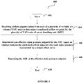
- a method for operating an air handling unit (AHU) at an effective static pressure setpoint comprising: receiving airflow setpoint values from each of a plurality of variable air volume (VAV) units to determine a combined airflow set point for the plurality of VAV units of an air handling unit (AHU); determining an effective static pressure setpoint for the AHU based on a relation between the combined airflow setpoint value and a static pressure represented by a system effect curve; and operating the AHU at the effective static pressure setpoint.
- VAV variable air volume
- a damper position of each VAV unit is monitored for determining a starving VAV unit from the plurality of VAV units and computing the effective static pressure setpoint of the AHU
- the method further comprises the steps of determining an offset for the starving VAV unit and adjusting the offset to the effective static pressure setpoint of the AHU for the starving VAV unit.
- the adjustment of the offset to the effective static pressure setpoint of the AHU is achieved by either increasing or decreasing the effective static pressure setpoint of the AHU
- the method further comprises the steps of automatically monitoring and learning an effect of the adjustment of the offset to the effective static pressure setpoint of the AHU for efficient operation of each of the plurality of VAV units.
- the method further comprises the steps of determining a second starving VAV unit and a second offset based on the effect of the adjustment of the offset to the effective static pressure setpoint of the AHU
- the airflow setpoint values of each of the plurality of VAV units is determined based on load requirement, a value of maximum allowed airflow setpoint & a value of minimum allowed airflow setpoint.
- the effective static pressure setpoint is obtained by varying the speed of a fan to meet the demand of the effective static pressure setpoint.
- the fan operates in accordance with the system effect curve to follow a least impedance airflow path.
- the AHU is connected with each of the VAV units through one or more ducts.
- the method further comprises steps of monitoring an existing static pressure control strategy instantaneous value at a defined interval time along with a recorded data to compare it with an impedance curve.
- the method further comprises steps of equating and showing energy losses to a user due to not following the impedance curve.
- a system for operating an air handling unit (AHU) at an effective static pressure setpoint comprising a plurality of variable air volume (VAV) units configured to determine airflow setpoint values and communicate the airflow setpoint values; and an air handling unit (AHU) comprising a controller, the controller configured to: receive the airflow setpoint values from each of the VAV units; determine a combined airflow set point for the plurality of VAV units of the AHU; determine an effective static pressure setpoint based on a relation between the combined airflow setpoint value and a static pressure represented by a system effect curve; and operate the AHU at the effective static pressure setpoint.
- VAV variable air volume
- the controller is further configured to monitor a damper position of each VAV unit for determining a starving VAV unit from the plurality of VAV units and compute the effective static pressure setpoint of the AHU
- controller is further configured to determine an offset for the starving VAV unit and adjust the offset to the effective static pressure setpoint of the AHU for the starving VAV unit.
- the adjustment of the offset to the effective static pressure setpoint of the AHU is achieved by either increasing or decreasing the effective static pressure setpoint of the AHU
- the controller is further configured to automatically monitor and learn an effect of the adjustment of the offset to the effective static pressure setpoint of the AHU for efficient operation of each of the plurality of VAV units.
- the controller is further configured to determine a second starving VAV unit and a second offset based on the effect of the adjustment of the offset to the effective static pressure setpoint of the AHU
- the effective static pressure setpoint is obtained by varying the speed of a fan to meet the demand of the effective static pressure setpoint.
- the fan operates in accordance with the system effect curve to follow a least impedance airflow path.
- the AHU is connected with each of the VAV units through one or more ducts.
- the airflow setpoint values of each of the plurality of VAV units is determined based on load requirement, a value of maximum allowed airflow setpoint and a value of minimum allowed airflow setpoint.
- Described herein is the technology with a system and a method for determining and operating an air handling unit (AHU) at an effective static pressure setpoint.
- AHU air handling unit
- Such AHU is connected to a plurality of variable air volume (referred hereinafter as VAV) units through one or more ducts in a HVAC system.
- the AHU of the HVAC system may be positioned on a roof or outside of a building or inside the building near any serving area.
- the AHU may be connected to one or more supply ducts and the one or more supply ducts may further be connected to the plurality of VAV units placed inside the building.
- the AHU may also be connected to one or more return ducts for drawing the air from inside the building and either releasing it back to the environment or partially mixing it with fresh air in the supply air duct.
- the plurality of VAV units may use one or more diffusers to provide the air in different zones of the building.
- Each of the VAV units may be responsible for maintaining a desired temperature in each zone.
- each of the plurality of VAV units may comprise an airflow sensor for measuring airflow of the VAV units.
- the AHU may also comprise an airflow sensor for measuring airflow within the AHU unit.
- the airflow sensor of each VAV unit may sense and communicate airflow setpoint values to a controller of the AHU for determining a combined airflow set point for the plurality of VAV units of the AHU Upon receiving the airflow setpoint values from the airflow sensor of each VAV unit, the controller may determine an effective static pressure setpoint for the AHU based on a relation between the combined airflow setpoint value and a static pressure represented by a system effect curve. Accordingly, the AHU may be operated at the effective static pressure setpoint as determined.
- reference numeral 104 depicts all ducts.
- the reference numerals 104A-104D (104) may be considered as a separate duct in a HVAC system.
- reference numeral 106 depicts all VAV units.
- the reference numerals 106A-106N (106) may be considered as a separate VAV unit in the HVAC system.
- reference numeral 108 depicts all diffusers. Each of the reference numerals 108A-108Z may be considered as a separate diffuser.
- reference numeral 110 depicts all zones. Each of the reference numerals 110A-110N may be considered as a separate zone.
- FIG. 1 depicts an exemplary system architecture 100 according to an exemplary embodiment of the invention.
- an air handling unit (AHU) 102 may be connected with a plurality of variable air volume (VAV) units 106A-106N through one or more ducts 104.
- a first duct 104A may supply air (fresh or conditioned air) to a second duct 104B, a third duct 104C and a fourth duct 104N.
- the second duct 104B may supply the air to a first VAV unit 106A
- the third duct 104C may supply the air to a second VAV unit 106B
- the fourth duct 104N may supply the air to a third VAV unit 106N.
- FIG. 1 only three VAV units are shown in Figure 1 ; however, any "n" number of VAV units may be connected to the AHU 102.
- the first VAV unit 106A may supply the air in a first zone 110A through one or more diffusers 108A, 108B and 108C.
- the second VAV unit 106B may supply the air in a second zone 110B through one or more diffusers 108D, 108E and 108F.
- the third VAV unit 106N may supply the air in a third zone 110N through one or more diffusers 108X, 108Y, and 108Z.
- Each of the VAV units 106 may maintain different temperature in each zone based on a temperature either desired by occupants in that particular zone or set by a user.
- the air present in each zone 110 may be returned/circulated back to the AHU 102 through one or more return ducts (not shown) connected to the VAV units 106 and to the AHU 102.
- a functional curve may be acquired for operating parameters (such as fan speed, duct static pressure setpoint, sum of airflow value of all VAVs units served by same AHU etc.) of the AHU 102, airflow setpoint of the plurality of VAV units 106A-106N etc.
- Such a functional curve may be compared with an ideal curve to determine deviations of the functional curve from the ideal curve.
- the functional curve may be a curve obtained based on actual operation and functioning of the AHU 102 and the plurality of VAV units 106A-106N.
- the ideal curve may be a curve obtained based on an expected functioning and operation of the AHU 102 which is provided by a manufacturer of the AHU
- each of the plurality of VAV units 106A-106N may determine or equate airflow setpoints value based on a percentage of heating/cooling load requirement, a value of a minimum airflow setpoint and a value of a maximum airflow setpoint.
- the airflow sensor of each VAV unit 106 may also communicate the determined/equated airflow setpoints value to a controller of the AHU 102. For an instance, an airflow sensor of the first VAV unit 106A senses 100 cubic feet per minute (cfm), an airflow sensor of the second VAV unit 106B senses 1000 cfm, and an airflow sensor of the third VAV unit 106N senses 2000 cfm.
- the controller may determine a combined airflow set point for the plurality of VAV units.
- the controller determines the combined airflow set point as 3100 cfm (i.e. 100+1000+2000 cfm from each VAV unit 106) using above equation.
- the controller may further determine an effective static pressure setpoint for the AHU 102 based on a relation between the combined airflow setpoint value (i.e. 3100 cfm) and a static pressure represented by a system effect curve.
- an AHU impedance curve defining a static pressure to an airflow relation is also taken into consideration for determining an effective static pressure setpoint for the AHU 102. Accordingly, the controller of the AHU 102 may automatically operate the AHU 102 at the determined effective static pressure setpoint.
- the effective static pressure setpoint is obtained by varying the speed of a fan of the AHU 102 to meet the demand of the effective static pressure setpoint.
- the fan of the AHU 102 operates in accordance with the system effect curve to follow a least impedance airflow path.
- the impedance path refers to a path followed by the air from the AHU 102 to each VAV unit 106 through the ducts 104 having with joint, bents. Such impedance is caused in the airflow path due to the joint, bents in ducts, connections to the VAV units from the ducts 104 etc.
- the term "static pressure setpoint" may refer to a setpoint value settable in the controller of the air handling unit 102. It is used to control AHU supply fan speed to achieve AHU supply duct at a mention static pressure.
- the controller of the AHU 102 may also monitor damper position of each VAV unit 106 individually. Such monitoring of the damper position of each VAV unit 106 by the controller is determined using actuators present in each VAV unit 106. Further, the damper position of each VAV unit 106 is monitored periodically after a pre-determined period of time. Such pre-determined period of time may be set by a technician or an air balancer of the AHU 102. Based on automatic monitoring of the damper position of each VAV unit 106, the controller may determine a starving VAV unit from the plurality of VAV units.
- the starving VAV unit may be a VAV unit which is operating with less airflow setpoint value as compared to actual required airflow setpoint value for its effective functioning thereby, resulting in ineffective operation of the AHU 102 and the VAV units 106. Therefore, the starving VAV unit may be determined by comparing a pre-defined or ideal airflow setpoint value with an airflow setpoint value and static pressure setpoint at which the starving VAV is currently operating.
- the first VAV unit 106A can be considered as a starving unit herein as the first VAV unit 106A is currently operating at an airflow setpoint value of 100 cubic feet per minute (cfm) which is less than the pre-defined or ideal airflow setpoint value (say, 850 cfm).
- a starving VAV situation can be determined if maximum of damper position of all VAV units 106 is greater than 95% open than that VAV can be marked as a starving VAV unit or approaching a starving state. In case the starvation gets over offset situation due to change in load, which will be identified when maximum of all VAV damper position is less than 85% (user adjustable) for more than 4 minutes (user adjustable).
- the controller of the AHU 102 may determine an offset for the starving VAV unit.
- a user adjustable static pressure setpoint offset value (say, for example: 0.02 inwc (inches of water)) can be added to the effective static pressure setpoint in the AHU 102 (equated from the curve).
- Such adjusted offset will be monitored for a user adjustable period of time (for an example: 4 minutes). If still a starving VAV is found, then same value (0.02 inwc) of the offset is further added till no starving is found. Similarly, exact opposite i.e. offset removal will happen if an over-offset situation is found. It is be noted here that in no circumstance the total static pressure offset value will go in negative.
- the determined offset may be adjusted by the controller of the AHU 102 to the effective static pressure setpoint of the AHU 102 for the starving VAV unit 106A.
- the adjustment of the offset to the effective static pressure setpoint of the AHU 102 is achieved by either increasing or decreasing the effective static pressure setpoint of the AHU 102.
- the controller of the AHU 102 may receive an updated airflow setpoint values from each VAV units 106.
- the airflow sensor of the first VAV unit 106A senses 1100 cfm
- the airflow sensor of the second VAV unit 106B senses 2000 cfm
- the airflow sensor of the third VAV unit 106N senses 50 cfm.
- the controller may determine a second starving VAV unit i.e. 106N and accordingly determine a second offset. Accordingly, the controller may again adjust the second offset to the effective static pressure setpoint of the AHU.
- the controller may again automatically and periodically monitor and learn an effect of the adjustment of the second offset to the effective static pressure setpoint of the AHU 102 for efficient operation of each of the plurality of VAV units 106. This is done so as to maintain the required effective static pressure setpoint at the AHU 102 so that no VAV unit 106 becomes a starving VAV unit.
- the starvation problem of the VAV unit 106 is resolved by the present invention, And, automated determination and operation of the AHU 102 at the effective static pressure setpoint at the AHU 102 is achieved by the present invention.
- effort put by the technician on audit time & manual power will be saved.
- fan operates on or very close to the system effect curve hence, energy is saved on operation of the fan as least impedance path is followed. Accordingly, time of the technician is saved as the static pressure setpoint is set automatically.
- the present invention also encompasses monitoring of an existing static pressure control strategy instantaneous value at a defined interval time along with a recorded data to compare it with an impedance curve. Further, the present invention also encompasses equating and showing energy losses to a user due to not following the impedance curve.
- FIG. 2 depicts block diagram of different components of an exemplary air handling unit (AHU) 102 according to an exemplary embodiment of the invention.
- the AHU 102 may comprise of, but is not limited to, one or more fan/s 202, damper/s 204, temperature sensor/s 206, a pressure sensor 208, heating coil 210, cooling coil 212, an airflow sensor 214 and/or a controller 216.
- the one or more fan/s 202 may be configured to draw air from the surroundings/environment and may be configured to provide air to the heating coil 210 if heating is to be maintained in zones 110 or to the cooling coil 212 if cooling is to be maintained.
- the other fan/s of the one or more fan/s 202 may also be configured to draw the air outside from the AHU 102.
- the AHU may also comprise variable frequency drive (not shown) for modulating speed of the fan 202 and providing RPM value of the fan 202.
- the damper/s 204 may be configured to select appropriate return air & outside air to provide fresh air to each VAV unit 106 in a building and to use return air to retain the cold air.
- the temperature sensor/s 206 may be configured to sense temperature of the air in the AHU 102 and may communicate the sensed temperature to the controller 216.
- the controller 216 may also be configured to receive inputs from the pressure sensor 208.
- the pressure sensor 208 may be installed in the one or more supply ducts 104 and may be wired to the controller 216.
- Such pressure sensor 208 may be adapted to measure pressure inside the one or more ducts 104 and may provide a value of the measured pressure to the controller 216 for operating the AHU 102 at the effective static pressure setpoint.
- the airflow sensor 214 may be configured to sense airflow setpoint value in the AHU 102 and may communicate the sensed airflow to the controller 216.
- the controller 216 may further be configured to receive airflow setpoint values from each VAV unit 106 to determine a combined airflow set point for the VAV units 106 as discussed above in Figure 1 .
- the controller 216 may further be configured to determine an effective static pressure setpoint for the AHU 102 based on a relation between the combined airflow setpoint value and a static pressure represented by a system effect curve.
- the controller 216 may also configured to operate the AHU 102 at the effective pressure setpoint as discussed above in details.
- the controller 216 may also provide command/s to the fan 202, the damper/s 204, the cooling coil 212 and/or the heating coil 210.
- FIG. 3 depicts block diagram of different components of an exemplary variable volume (VAV) unit 106 according to an exemplary embodiment of the invention.
- the VAV unit 106 may comprise of, but is not limited to, damper/s 302, fan/s 304, an airflow sensor 306, a zone temperature sensor 308, an actuator 310 and/or a controller 312.
- the zone temperature sensor 308 may be configured to sense temperature in its respective zone 110.
- the controller 312 may be configured to provide a command to the actuator 310 for changing or maintaining a position of the damper 302 based on a command from the AHU 102 and the requirement of a desired temperature and to allow the air to pass through it.
- the controller 312 may further be configured to determine or equate airflow setpoint values of each of the plurality of VAV units 106 based on load requirement, a value of maximum allowed airflow setpoint & a value of minimum allowed airflow setpoint.
- the airflow sensor 306 may be configured to sense a flow of air in the VAV unit 106.
- the controller 310 may also be configured to control operations of the VAV unit 106 such as receiving temperature value from the zone temperature sensor 308, controlling temperature in each zone 110 based on cooling temperature setpoint to be achieved.
- the fan/s 304 may be adapted to provide or draw air from the VAV unit 106.
- FIG. 4 depicts a flowchart outlining the features of the invention in an exemplary embodiment of the invention.
- the method flowchart 400 describes a method being for operating an air handling unit (AHU) 102 at an effective static pressure setpoint in a HVAC system.
- the method flowchart 400 starts at step 402.
- a controller 216 of the AHU 102 may receive airflow setpoint values from each of a plurality of VAV units 106 to determine a combined airflow set point for the plurality of VAV units 106 of the AHU 102. This has been discussed in greater details in Figure 1 above.
- the controller 216 of the AHU 102 may determine an effective static pressure setpoint for the AHU 102 based on a relation between the combined airflow setpoint value and a static pressure represented by a system effect curve. This has been discussed in greater details in Figure 1 above.
- the controller 216 of the AHU 102 may operate the AHU 102 at the effective static pressure setpoint. This has been discussed in greater details in Figure 1 above. Then, the method flowchart 400 may end at 410.
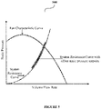
- Figure 5 depicts an exemplary graph 500 showing a relation between a fan characteristic curve, a system resistance curve and a system resistance curve with offset static pressure setpoint according to an exemplary embodiment of the invention.
- the system resistance curve and the system resistance curve with offset static pressure setpoint are determined and adjusted in order to operate the AHU 102 at the effective static pressure setpoint.
- the present invention is applicable in various industries/fields such as, but is not limited to, banking industry, hospitality industry, housing industry, building/construction industry, offices, universities, hospitals, colleges, homes and any such industry/field that is well known in the art and where HVAC systems are used.
- controller can refer to substantially any processor or computing processing unit or device comprising, but not limited to comprising, a direct digital control of a HVAC system, a zone controller of the HVAC system, single-core processors; single-processors with software multithread execution capability; multi-core processors; multi-core processors with software multithread execution capability; multi-core processors with hardware multithread technology; parallel platforms; and parallel platforms with distributed shared memory.
- a processor can refer to an integrated circuit, an application specific integrated circuit (ASIC), a digital signal processor (DSP), a field programmable gate array (FPGA), a programmable logic controller (PLC), a complex programmable logic device (CPLD), a discrete gate or transistor logic, discrete hardware components, or any combination thereof designed to perform the functions described herein.
- ASIC application specific integrated circuit
- DSP digital signal processor
- FPGA field programmable gate array
- PLC programmable logic controller
- CPLD complex programmable logic device
- a processor may also be implemented as a combination of computing processing units.
Landscapes
- Engineering & Computer Science (AREA)
- Chemical & Material Sciences (AREA)
- Combustion & Propulsion (AREA)
- Mechanical Engineering (AREA)
- General Engineering & Computer Science (AREA)
- Physics & Mathematics (AREA)
- Signal Processing (AREA)
- Fluid Mechanics (AREA)
- Fuzzy Systems (AREA)
- Mathematical Physics (AREA)
- Air Conditioning Control Device (AREA)
Abstract
Description
- The present invention generally relates to heating, ventilation, and air conditioning (referred hereinafter as "HVAC") system. More particularly, the invention relates to a system and a method for operating an air handling unit (AHU) at an effective static pressure setpoint.
- Heating, ventilation, and air conditioning (HVAC) systems are used in residential/commercial places for cooling or heating a building. In order to maintain cooling or heating in the building, a HVAC system uses an air handling unit (AHU) and one or more variable air volume (referred hereinafter as "VAV") units. Each of the VAV units may use diffusers to serve different zones/areas of the building. Particularly, each zone of the building may have a few diffusers connected with a VAV unit for maintaining a desired temperature in that zone. This helps in maintaining different cooling or heating temperatures at the same time in various zones of the building.
- To ensure efficient and effective functioning of the AHU and the VAV unit, it becomes critical to draft a functional curve so that a deviation from an ideal curve can be seen. Such deviation can help to provide a benchmark and also provides information on whether an installation of the AHU, the VAV units etc. in the HVAC system is done properly or not. Currently, there is no mechanism to gauge the functional curve at an installation site and determine losses that might have occurred affecting the overall functioning of the AHU and the VAV units. Further, in order to determine cause for the losses in the AHU, the VAV units etc., a technician has to physically check each and every part of the entire HVAC system; but still the technician may not be able to detect all defects causing such losses. In addition, such a process is a time-consuming and labor-intensive task.
- In order to meet the end requirements of cooling and heating in the building, static pressure setpoint in the AHU needs to be maintained by controlling fan speed of the AHU. Further, for controlling the fan speed of the AHU, static pressure setpoint of the AHU is kept at a constant value which operates in a system resistance curve i.e. static pressure/ cubic feet per minute (cfm) when the speed of the fan varies. Alternatively, the static pressure of the AHU can be reset using a trim & respond method which operates by monitoring a maximum value of a damper position of all VAV units & for higher position value, the static pressure setpoint is increased & vice versa clamping to a higher or a lower limit which are manually calculated/approximated. However, the trim & respond method is inefficient due to randomly changing static pressure which may not follow a system impedance curve. Also, dampers of the VAV units are in an intermediate position which adds impedance in an airflow casing system curve to deflect inwards, thereby resulting in more losses. In order to determine the AHU static pressure setpoint, a balancer requires a lot of time and does all the work manually to define the static pressure setpoint. Further, any HVAC system is designed based on the requirements at the location where the system is installed. But the actual installation requires several changes and adjustments in piping/ductwork of the HVAC. Accordingly, the designed HVAC systems seldom work ideally as planned.
- In view of the afore-mentioned problems, there is a need of an efficient and effective system and a method for determining a static pressure setpoint of an AHU. There is also a requirement to reduce the time taken by a balancer for manually determining the static pressure setpoint of the AHU. In order to solve the problems in the existing solutions, a system and a method are disclosed.
- According to a first aspect of the invention, there is provided a method for operating an air handling unit (AHU) at an effective static pressure setpoint, the method comprising: receiving airflow setpoint values from each of a plurality of variable air volume (VAV) units to determine a combined airflow set point for the plurality of VAV units of an air handling unit (AHU); determining an effective static pressure setpoint for the AHU based on a relation between the combined airflow setpoint value and a static pressure represented by a system effect curve; and operating the AHU at the effective static pressure setpoint.
- Optionally, a damper position of each VAV unit is monitored for determining a starving VAV unit from the plurality of VAV units and computing the effective static pressure setpoint of the AHU
- Optionally, the method further comprises the steps of determining an offset for the starving VAV unit and adjusting the offset to the effective static pressure setpoint of the AHU for the starving VAV unit.
- Optionally, the adjustment of the offset to the effective static pressure setpoint of the AHU is achieved by either increasing or decreasing the effective static pressure setpoint of the AHU
- Optionally, the method further comprises the steps of automatically monitoring and learning an effect of the adjustment of the offset to the effective static pressure setpoint of the AHU for efficient operation of each of the plurality of VAV units.
- Optionally, the method further comprises the steps of determining a second starving VAV unit and a second offset based on the effect of the adjustment of the offset to the effective static pressure setpoint of the AHU
- Optionally, the airflow setpoint values of each of the plurality of VAV units is determined based on load requirement, a value of maximum allowed airflow setpoint & a value of minimum allowed airflow setpoint.
- Optionally, the effective static pressure setpoint is obtained by varying the speed of a fan to meet the demand of the effective static pressure setpoint.
- Optionally, the fan operates in accordance with the system effect curve to follow a least impedance airflow path.
- Optionally, the AHU is connected with each of the VAV units through one or more ducts.
- Optionally, the method further comprises steps of monitoring an existing static pressure control strategy instantaneous value at a defined interval time along with a recorded data to compare it with an impedance curve.
- Optionally, the method further comprises steps of equating and showing energy losses to a user due to not following the impedance curve.
- According to a second aspect of the invention there is provided a system for operating an air handling unit (AHU) at an effective static pressure setpoint, the system comprising a plurality of variable air volume (VAV) units configured to determine airflow setpoint values and communicate the airflow setpoint values; and an air handling unit (AHU) comprising a controller, the controller configured to: receive the airflow setpoint values from each of the VAV units; determine a combined airflow set point for the plurality of VAV units of the AHU; determine an effective static pressure setpoint based on a relation between the combined airflow setpoint value and a static pressure represented by a system effect curve; and operate the AHU at the effective static pressure setpoint.
- Optionally, the controller is further configured to monitor a damper position of each VAV unit for determining a starving VAV unit from the plurality of VAV units and compute the effective static pressure setpoint of the AHU
- Optionally, the controller is further configured to determine an offset for the starving VAV unit and adjust the offset to the effective static pressure setpoint of the AHU for the starving VAV unit.
- Optionally, the adjustment of the offset to the effective static pressure setpoint of the AHU is achieved by either increasing or decreasing the effective static pressure setpoint of the AHU
- Optionally, the controller is further configured to automatically monitor and learn an effect of the adjustment of the offset to the effective static pressure setpoint of the AHU for efficient operation of each of the plurality of VAV units.
- Optionally, the controller is further configured to determine a second starving VAV unit and a second offset based on the effect of the adjustment of the offset to the effective static pressure setpoint of the AHU
- Optionally, the effective static pressure setpoint is obtained by varying the speed of a fan to meet the demand of the effective static pressure setpoint.
- Optionally, the fan operates in accordance with the system effect curve to follow a least impedance airflow path.
- Optionally, the AHU is connected with each of the VAV units through one or more ducts.
- Optionally, the airflow setpoint values of each of the plurality of VAV units is determined based on load requirement, a value of maximum allowed airflow setpoint and a value of minimum allowed airflow setpoint.
- This summary is provided to introduce a selection of concepts in a simplified form that are further described below in the detailed description. This summary is not intended to identify key features or essential features of the claimed subject matter, nor is it intended to be used as an aid in determining the scope of the claimed subject matter.
- Other aspects, advantages, and salient features of the invention will become apparent to those skilled in the art from the following detailed description, which taken in conjunction with the annexed drawings, discloses exemplary embodiments of the invention.
-
Figure 1 depicts an exemplary system architecture. -
Figure 2 depicts block diagram of different components of an exemplary air handling unit. -
Figure 3 depicts block diagram of different components of an exemplary variable air volume (VAV) unit. -
Figure 4 depicts an exemplary flowchart illustrating an exemplary method. -
Figure 5 depicts an exemplary graph showing relation between a fan characteristic curve, a system resistance curve and a system resistance curve with offset static pressure setpoint. - Corresponding reference numerals indicate corresponding parts throughout the drawings.
- Described herein is the technology with a system and a method for determining and operating an air handling unit (AHU) at an effective static pressure setpoint. Such AHU is connected to a plurality of variable air volume (referred hereinafter as VAV) units through one or more ducts in a HVAC system. The AHU of the HVAC system may be positioned on a roof or outside of a building or inside the building near any serving area. The AHU may be connected to one or more supply ducts and the one or more supply ducts may further be connected to the plurality of VAV units placed inside the building. The AHU may also be connected to one or more return ducts for drawing the air from inside the building and either releasing it back to the environment or partially mixing it with fresh air in the supply air duct. When the air from the AHU reaches the plurality of VAV units, the plurality of VAV units may use one or more diffusers to provide the air in different zones of the building. Each of the VAV units may be responsible for maintaining a desired temperature in each zone.
- Moreover, each of the plurality of VAV units may comprise an airflow sensor for measuring airflow of the VAV units. Similarly, the AHU may also comprise an airflow sensor for measuring airflow within the AHU unit. The airflow sensor of each VAV unit may sense and communicate airflow setpoint values to a controller of the AHU for determining a combined airflow set point for the plurality of VAV units of the AHU Upon receiving the airflow setpoint values from the airflow sensor of each VAV unit, the controller may determine an effective static pressure setpoint for the AHU based on a relation between the combined airflow setpoint value and a static pressure represented by a system effect curve. Accordingly, the AHU may be operated at the effective static pressure setpoint as determined.
- Throughout the specification, reference numeral 104 depicts all ducts. The reference numerals 104A-104D (104) may be considered as a separate duct in a HVAC system. Also, throughout the specification,
reference numeral 106 depicts all VAV units. The reference numerals 106A-106N (106) may be considered as a separate VAV unit in the HVAC system. Similarly, throughout the specification, reference numeral 108 depicts all diffusers. Each of thereference numerals 108A-108Z may be considered as a separate diffuser. Lastly, throughout the specification, reference numeral 110 depicts all zones. Each of thereference numerals 110A-110N may be considered as a separate zone. -
Figure 1 depicts anexemplary system architecture 100 according to an exemplary embodiment of the invention. As depicted inFigure 1 , an air handling unit (AHU) 102 may be connected with a plurality of variable air volume (VAV)units 106A-106N through one or more ducts 104. Afirst duct 104A may supply air (fresh or conditioned air) to asecond duct 104B, athird duct 104C and afourth duct 104N. As depicted inFigure 1 , thesecond duct 104B may supply the air to afirst VAV unit 106A, thethird duct 104C may supply the air to asecond VAV unit 106B and thefourth duct 104N may supply the air to athird VAV unit 106N. Although, only three VAV units are shown inFigure 1 ; however, any "n" number of VAV units may be connected to theAHU 102. - When the air flowing through the
ducts 104A-104N reaches thefirst VAV unit 106A, thefirst VAV unit 106A may supply the air in afirst zone 110A through one or more diffusers 108A, 108B and 108C. Similarly, thesecond VAV unit 106B may supply the air in asecond zone 110B through one ormore diffusers third VAV unit 106N may supply the air in athird zone 110N through one ormore diffusers VAV units 106 may maintain different temperature in each zone based on a temperature either desired by occupants in that particular zone or set by a user. In addition, the air present in each zone 110 may be returned/circulated back to theAHU 102 through one or more return ducts (not shown) connected to theVAV units 106 and to theAHU 102. - When the
AHU 102 and the plurality ofVAV units 106A-106N gets operational after the completion of the installation and commissioning work, a functional curve may be acquired for operating parameters (such as fan speed, duct static pressure setpoint, sum of airflow value of all VAVs units served by same AHU etc.) of theAHU 102, airflow setpoint of the plurality ofVAV units 106A-106N etc. Such a functional curve may be compared with an ideal curve to determine deviations of the functional curve from the ideal curve. As used herein, the functional curve may be a curve obtained based on actual operation and functioning of theAHU 102 and the plurality ofVAV units 106A-106N. As used herein, the ideal curve may be a curve obtained based on an expected functioning and operation of theAHU 102 which is provided by a manufacturer of the AHU - Further, each of the plurality of
VAV units 106A-106N may determine or equate airflow setpoints value based on a percentage of heating/cooling load requirement, a value of a minimum airflow setpoint and a value of a maximum airflow setpoint. The airflow sensor of eachVAV unit 106 may also communicate the determined/equated airflow setpoints value to a controller of theAHU 102. For an instance, an airflow sensor of thefirst VAV unit 106A senses 100 cubic feet per minute (cfm), an airflow sensor of thesecond VAV unit 106B senses 1000 cfm, and an airflow sensor of thethird VAV unit 106N senses 2000 cfm. Once the controller receives the airflow setpoints value from each of theVAV unit 106, the controller may determine a combined airflow set point for the plurality of VAV units. In an embodiment, the controller may determine the combined airflow set point by using following formula:
- For an instance, the controller determines the combined airflow set point as 3100 cfm (i.e. 100+1000+2000 cfm from each VAV unit 106) using above equation. The controller may further determine an effective static pressure setpoint for the
AHU 102 based on a relation between the combined airflow setpoint value (i.e. 3100 cfm) and a static pressure represented by a system effect curve. In addition, an AHU impedance curve defining a static pressure to an airflow relation is also taken into consideration for determining an effective static pressure setpoint for theAHU 102. Accordingly, the controller of theAHU 102 may automatically operate theAHU 102 at the determined effective static pressure setpoint. In an exemplary embodiment, the effective static pressure setpoint is obtained by varying the speed of a fan of theAHU 102 to meet the demand of the effective static pressure setpoint. Further, the fan of theAHU 102 operates in accordance with the system effect curve to follow a least impedance airflow path. Herein, the impedance path refers to a path followed by the air from theAHU 102 to eachVAV unit 106 through the ducts 104 having with joint, bents. Such impedance is caused in the airflow path due to the joint, bents in ducts, connections to the VAV units from the ducts 104 etc. As used herein, the term "static pressure setpoint" may refer to a setpoint value settable in the controller of theair handling unit 102. It is used to control AHU supply fan speed to achieve AHU supply duct at a mention static pressure. - Moreover, the controller of the
AHU 102 may also monitor damper position of eachVAV unit 106 individually. Such monitoring of the damper position of eachVAV unit 106 by the controller is determined using actuators present in eachVAV unit 106. Further, the damper position of eachVAV unit 106 is monitored periodically after a pre-determined period of time. Such pre-determined period of time may be set by a technician or an air balancer of theAHU 102. Based on automatic monitoring of the damper position of eachVAV unit 106, the controller may determine a starving VAV unit from the plurality of VAV units. In an exemplary embodiment, the starving VAV unit may be a VAV unit which is operating with less airflow setpoint value as compared to actual required airflow setpoint value for its effective functioning thereby, resulting in ineffective operation of theAHU 102 and theVAV units 106. Therefore, the starving VAV unit may be determined by comparing a pre-defined or ideal airflow setpoint value with an airflow setpoint value and static pressure setpoint at which the starving VAV is currently operating. For an example, thefirst VAV unit 106A can be considered as a starving unit herein as thefirst VAV unit 106A is currently operating at an airflow setpoint value of 100 cubic feet per minute (cfm) which is less than the pre-defined or ideal airflow setpoint value (say, 850 cfm). In an exemplary embodiment, a starving VAV situation can be determined if maximum of damper position of allVAV units 106 is greater than 95% open than that VAV can be marked as a starving VAV unit or approaching a starving state. In case the starvation gets over offset situation due to change in load, which will be identified when maximum of all VAV damper position is less than 85% (user adjustable) for more than 4 minutes (user adjustable). - After the starving
VAV unit 106A is determined, the controller of theAHU 102 may determine an offset for the starving VAV unit. In an exemplary embodiment, a user adjustable static pressure setpoint offset value (say, for example: 0.02 inwc (inches of water)) can be added to the effective static pressure setpoint in the AHU 102 (equated from the curve). Such adjusted offset will be monitored for a user adjustable period of time (for an example: 4 minutes). If still a starving VAV is found, then same value (0.02 inwc) of the offset is further added till no starving is found. Similarly, exact opposite i.e. offset removal will happen if an over-offset situation is found. It is be noted here that in no circumstance the total static pressure offset value will go in negative. The determined offset may be adjusted by the controller of theAHU 102 to the effective static pressure setpoint of theAHU 102 for the starvingVAV unit 106A. In other words, the adjustment of the offset to the effective static pressure setpoint of theAHU 102 is achieved by either increasing or decreasing the effective static pressure setpoint of theAHU 102. - After some time (say after 1 hour), the controller of the
AHU 102 may receive an updated airflow setpoint values from eachVAV units 106. Consider another instance, the airflow sensor of thefirst VAV unit 106A senses 1100 cfm, the airflow sensor of thesecond VAV unit 106B senses 2000 cfm, and the airflow sensor of thethird VAV unit 106N senses 50 cfm. On receiving the updated airflow setpoint values, the controller may determine a second starving VAV unit i.e. 106N and accordingly determine a second offset. Accordingly, the controller may again adjust the second offset to the effective static pressure setpoint of the AHU. On adjusting the offset to the effective static pressure setpoint of theAHU 102, the controller may again automatically and periodically monitor and learn an effect of the adjustment of the second offset to the effective static pressure setpoint of theAHU 102 for efficient operation of each of the plurality ofVAV units 106. This is done so as to maintain the required effective static pressure setpoint at theAHU 102 so that noVAV unit 106 becomes a starving VAV unit. - Therefore, the starvation problem of the
VAV unit 106 is resolved by the present invention, And, automated determination and operation of theAHU 102 at the effective static pressure setpoint at theAHU 102 is achieved by the present invention. By doing this, effort put by the technician on audit time & manual power will be saved. Also, fan operates on or very close to the system effect curve hence, energy is saved on operation of the fan as least impedance path is followed. Accordingly, time of the technician is saved as the static pressure setpoint is set automatically. - The present invention also encompasses monitoring of an existing static pressure control strategy instantaneous value at a defined interval time along with a recorded data to compare it with an impedance curve. Further, the present invention also encompasses equating and showing energy losses to a user due to not following the impedance curve.
-
Figure 2 depicts block diagram of different components of an exemplary air handling unit (AHU) 102 according to an exemplary embodiment of the invention. TheAHU 102 may comprise of, but is not limited to, one or more fan/s 202, damper/s 204, temperature sensor/s 206, apressure sensor 208,heating coil 210, coolingcoil 212, anairflow sensor 214 and/or acontroller 216. The one or more fan/s 202 may be configured to draw air from the surroundings/environment and may be configured to provide air to theheating coil 210 if heating is to be maintained in zones 110 or to thecooling coil 212 if cooling is to be maintained. The other fan/s of the one or more fan/s 202 may also be configured to draw the air outside from theAHU 102. The AHU may also comprise variable frequency drive (not shown) for modulating speed of thefan 202 and providing RPM value of thefan 202. The damper/s 204 may be configured to select appropriate return air & outside air to provide fresh air to eachVAV unit 106 in a building and to use return air to retain the cold air. The temperature sensor/s 206 may be configured to sense temperature of the air in theAHU 102 and may communicate the sensed temperature to thecontroller 216. Moreover, thecontroller 216 may also be configured to receive inputs from thepressure sensor 208. Thepressure sensor 208 may be installed in the one or more supply ducts 104 and may be wired to thecontroller 216.Such pressure sensor 208 may be adapted to measure pressure inside the one or more ducts 104 and may provide a value of the measured pressure to thecontroller 216 for operating theAHU 102 at the effective static pressure setpoint. Theairflow sensor 214 may be configured to sense airflow setpoint value in theAHU 102 and may communicate the sensed airflow to thecontroller 216. Thecontroller 216 may further be configured to receive airflow setpoint values from eachVAV unit 106 to determine a combined airflow set point for theVAV units 106 as discussed above inFigure 1 . Thecontroller 216 may further be configured to determine an effective static pressure setpoint for theAHU 102 based on a relation between the combined airflow setpoint value and a static pressure represented by a system effect curve. Accordingly, thecontroller 216 may also configured to operate theAHU 102 at the effective pressure setpoint as discussed above in details. Thecontroller 216 may also provide command/s to thefan 202, the damper/s 204, the coolingcoil 212 and/or theheating coil 210. -
Figure 3 depicts block diagram of different components of an exemplary variable volume (VAV)unit 106 according to an exemplary embodiment of the invention. TheVAV unit 106 may comprise of, but is not limited to, damper/s 302, fan/s 304, anairflow sensor 306, azone temperature sensor 308, anactuator 310 and/or acontroller 312. Thezone temperature sensor 308 may be configured to sense temperature in its respective zone 110. Thecontroller 312 may be configured to provide a command to theactuator 310 for changing or maintaining a position of thedamper 302 based on a command from theAHU 102 and the requirement of a desired temperature and to allow the air to pass through it. Thecontroller 312 may further be configured to determine or equate airflow setpoint values of each of the plurality ofVAV units 106 based on load requirement, a value of maximum allowed airflow setpoint & a value of minimum allowed airflow setpoint. Theairflow sensor 306 may be configured to sense a flow of air in theVAV unit 106. Thecontroller 310 may also be configured to control operations of theVAV unit 106 such as receiving temperature value from thezone temperature sensor 308, controlling temperature in each zone 110 based on cooling temperature setpoint to be achieved. The fan/s 304 may be adapted to provide or draw air from theVAV unit 106. -
Figure 4 depicts a flowchart outlining the features of the invention in an exemplary embodiment of the invention. Themethod flowchart 400 describes a method being for operating an air handling unit (AHU) 102 at an effective static pressure setpoint in a HVAC system. Themethod flowchart 400 starts atstep 402. - At
step 404, acontroller 216 of theAHU 102 may receive airflow setpoint values from each of a plurality ofVAV units 106 to determine a combined airflow set point for the plurality ofVAV units 106 of theAHU 102. This has been discussed in greater details inFigure 1 above. - At
step 406, thecontroller 216 of theAHU 102 may determine an effective static pressure setpoint for theAHU 102 based on a relation between the combined airflow setpoint value and a static pressure represented by a system effect curve. This has been discussed in greater details inFigure 1 above. - At
step 408, thecontroller 216 of theAHU 102 may operate theAHU 102 at the effective static pressure setpoint. This has been discussed in greater details inFigure 1 above. Then, themethod flowchart 400 may end at 410. -
Figure 5 depicts anexemplary graph 500 showing a relation between a fan characteristic curve, a system resistance curve and a system resistance curve with offset static pressure setpoint according to an exemplary embodiment of the invention. As explained above inFigure 1 , the system resistance curve and the system resistance curve with offset static pressure setpoint are determined and adjusted in order to operate theAHU 102 at the effective static pressure setpoint. - The present invention is applicable in various industries/fields such as, but is not limited to, banking industry, hospitality industry, housing industry, building/construction industry, offices, universities, hospitals, colleges, homes and any such industry/field that is well known in the art and where HVAC systems are used.
- The embodiments of the invention discussed herein are exemplary and various modification and alterations to a person skilled in the art are within the scope of the invention.
- The order of execution or performance of the operations in examples of the invention illustrated and described herein is not essential, unless otherwise specified. That is, the operations may be performed in any order, unless otherwise specified, and examples of the invention may include additional or fewer operations than those disclosed herein. For example, it is contemplated that executing or performing a particular operation before, contemporaneously with, or after another operation is within the scope of aspects of the invention.
- As it employed in the subject specification, the term "controller" can refer to substantially any processor or computing processing unit or device comprising, but not limited to comprising, a direct digital control of a HVAC system, a zone controller of the HVAC system, single-core processors; single-processors with software multithread execution capability; multi-core processors; multi-core processors with software multithread execution capability; multi-core processors with hardware multithread technology; parallel platforms; and parallel platforms with distributed shared memory. Additionally, a processor can refer to an integrated circuit, an application specific integrated circuit (ASIC), a digital signal processor (DSP), a field programmable gate array (FPGA), a programmable logic controller (PLC), a complex programmable logic device (CPLD), a discrete gate or transistor logic, discrete hardware components, or any combination thereof designed to perform the functions described herein. Processors can exploit nano-scale architectures such as, but not limited to, molecular and quantum-dot based transistors, switches and gates, in order to optimize space usage or enhance performance of user equipment. A processor may also be implemented as a combination of computing processing units.
- When introducing elements of aspects of the invention or the examples thereof, the articles "a," "an," "the," and "said" are intended to mean that there are one or more of the elements. The terms "comprising," "including," and "having" are intended to be inclusive and mean that there may be additional elements other than the listed elements. The term "exemplary" is intended to mean "an example of." The phrase "one or more of the following: A, B, and C" means "at least one of A and/or at least one of B and/or at least one of C".
- Having described aspects of the invention in detail, it will be apparent that modifications and variations are possible without departing from the scope of aspects of the invention as defined in the appended claims. As various changes could be made in the above constructions, products, and methods without departing from the scope of aspects of the invention, it is intended that all matter contained in the above description and shown in the accompanying drawings shall be interpreted as illustrative and not in a limiting sense.
- Although the subject matter has been described in language specific to structural features and/or acts, it is to be understood that the subject matter defined in the appended claims is not necessarily limited to the specific features or acts described above. Rather, the specific features and acts described above are disclosed as examples of implementing the claims and other equivalent features and acts are intended to be within the scope of the claims.
Claims (15)
- A method (400) comprising:- receiving (404) airflow setpoint values from each of a plurality of variable air volume VAV units (106A, 106B, ..., 106N) to determine a combined airflow set point for the plurality of VAV units of an air handling unit AHU (102);- determining (406) an effective static pressure setpoint for the AHU based on a relation between the combined airflow setpoint value and a static pressure represented by a system effect curve; and- operating (408) the AHU at the effective static pressure setpoint.
- The method of claim 1, further comprising: monitoring a damper position of each VAV unit (106A, 106B, ..., 106N) for determining a starving VAV unit from the plurality of VAV units and computing the effective static pressure setpoint of the AHU (102).
- The method of claim 2, further comprising:determining an offset for the starving VAV unit (106A, 106B, ..., 106N); andadjusting the offset to the effective static pressure setpoint of the AHU (102) for the starving VAV unit.
- The method of claim 3, wherein the adjustment of the offset to the effective static pressure setpoint of the AHU (102) is achieved by either increasing or decreasing the effective static pressure setpoint of the AHU
- The method of claim 2 or claim 3, further comprising:automatically monitoring and learning an effect of the adjustment of the offset to the effective static pressure setpoint of the AHU (102) for efficient operation of each of the plurality of VAV units (106A, 106B, ..., 106N); and/ordetermining a second starving VAV unit (106A, 106B, ..., 106N) and a second offset based on the effect of the adjustment of the offset to the effective static pressure setpoint of the AHU (102).
- The method of any preceding claim, wherein the airflow setpoint values of each of the plurality of VAV units (106A, 106B, ..., 106N) is determined based on load requirement, a value of maximum allowed airflow setpoint and a value of minimum allowed airflow setpoint; and/or wherein the AHU (102) is connected with each of the VAV units (106A, 106B, ..., 106N) through one or more ducts (104A, 104B, ..., 104N).
- The method of any preceding claim, wherein the effective static pressure setpoint is obtained by varying the speed of a fan (202) to meet the demand of the effective static pressure setpoint; optionally wherein the fan operates in accordance with the system effect curve to follow a least impedance airflow path.
- The method of any preceding claim, further comprising: monitoring an existing static pressure control strategy instantaneous value at a defined interval time along with a recorded data to compare it with an impedance curve; and optionally further comprising: equating and showing energy losses to a user due to not following the impedance curve.
- A system (100) comprising:- a plurality of variable air volume VAV units (106A, 106B, ..., 106N) configured to determine airflow setpoint values and communicate the airflow setpoint values; and- an air handling unit AHU (102) comprising a controller (216) configured to:receive the airflow setpoint values from each of the VAV units;determine a combined airflow set point for the plurality of VAV units of the AHU;determine an effective static pressure setpoint based on a relation between the combined airflow setpoint value and a static pressure represented by a system effect curve; andoperate the AHU at the effective static pressure setpoint.
- The system of claim 9, wherein the controller (216) is further configured to:
monitor a damper position of each VAV unit (106A, 106B, ..., 106N) for determining a starving VAV unit from the plurality of VAV units and compute the effective static pressure setpoint of the AHU (102). - The system of claim 10, wherein the controller (216) is further configured to:determine an offset for the starving VAV unit (106A, 106B, ..., 106N); andadjust the offset to the effective static pressure setpoint of the AHU (102) for the starving VAV unit.
- The system of claim 11, wherein the adjustment of the offset to the effective static pressure setpoint of the AHU (102) is achieved by either increasing or decreasing the effective static pressure setpoint of the AHU
- The system of claim 11 or claim 12, wherein the controller (216) is further configured to:automatically monitor and learn an effect of the adjustment of the offset to the effective static pressure setpoint of the AHU (102) for efficient operation of each of the plurality of VAV units (106A, 106B, ..., 106N); and/ordetermine a second starving VAV unit (106A, 106B, ..., 106N) and a second offset based on the effect of the adjustment of the offset to the effective static pressure setpoint of the AHU (102).
- The system of any of claims 9 to 13, wherein the effective static pressure setpoint is obtained by varying the speed of a fan (202) to meet the demand of the effective static pressure setpoint; optionally wherein the fan operates in accordance with the system effect curve to follow a least impedance airflow path.
- The system of any of claims 9 to 14, wherein the airflow setpoint values of each of the plurality of VAV units (106A, 106B, ..., 106N) is determined based on load requirement, a value of maximum allowed airflow setpoint and a value of minimum allowed airflow setpoint; and/or wherein the AHU (102) is connected with each of the VAV units through one or more ducts (104A, 104B, ..., 104N).
Applications Claiming Priority (1)
| Application Number | Priority Date | Filing Date | Title |
|---|---|---|---|
| IN202011052896 | 2020-12-04 |
Publications (1)
| Publication Number | Publication Date |
|---|---|
| EP4008972A1 true EP4008972A1 (en) | 2022-06-08 |
Family
ID=78821921
Family Applications (1)
| Application Number | Title | Priority Date | Filing Date |
|---|---|---|---|
| EP21212494.5A Pending EP4008972A1 (en) | 2020-12-04 | 2021-12-06 | A method and a system for operating an air handling unit at effective static pressure |
Country Status (2)
| Country | Link |
|---|---|
| US (1) | US11835251B2 (en) |
| EP (1) | EP4008972A1 (en) |
Families Citing this family (1)
| Publication number | Priority date | Publication date | Assignee | Title |
|---|---|---|---|---|
| WO2023150827A1 (en) * | 2022-02-08 | 2023-08-17 | Kaip Pty Limited | Vav diffuser controls |
Citations (3)
| Publication number | Priority date | Publication date | Assignee | Title |
|---|---|---|---|---|
| US5863246A (en) * | 1997-12-15 | 1999-01-26 | Carrier Corporation | Variable air volume control system |
| US20060116067A1 (en) * | 2004-12-01 | 2006-06-01 | Federspiel Clifford C | Method and apparatus for determining critical pressure of variable air volume heating, ventilating, and air-conditioning systems |
| JP2018173206A (en) * | 2017-03-31 | 2018-11-08 | アズビル株式会社 | Vav unit control device and control method for vav unit |
Family Cites Families (4)
| Publication number | Priority date | Publication date | Assignee | Title |
|---|---|---|---|---|
| US6116095A (en) * | 1998-11-09 | 2000-09-12 | White Consolidated Industries, Inc. | Apparatus and method for measuring air flow from a duct system |
| US8235777B2 (en) * | 2005-05-03 | 2012-08-07 | Daniel Stanimirovic | Fully articulated and comprehensive air and fluid distribution, metering and control method and apparatus for primary movers, heat exchangers, and terminal flow devices |
| US11416739B2 (en) * | 2018-01-29 | 2022-08-16 | Lawrence Livermore National Security, Llc | Optimization control technology for building energy conservation |
| US20220058497A1 (en) * | 2020-08-21 | 2022-02-24 | Siemens Industry, Inc. | Systems and methods for fault diagnostics in building automation systems |
-
2021
- 2021-11-24 US US17/534,755 patent/US11835251B2/en active Active
- 2021-12-06 EP EP21212494.5A patent/EP4008972A1/en active Pending
Patent Citations (3)
| Publication number | Priority date | Publication date | Assignee | Title |
|---|---|---|---|---|
| US5863246A (en) * | 1997-12-15 | 1999-01-26 | Carrier Corporation | Variable air volume control system |
| US20060116067A1 (en) * | 2004-12-01 | 2006-06-01 | Federspiel Clifford C | Method and apparatus for determining critical pressure of variable air volume heating, ventilating, and air-conditioning systems |
| JP2018173206A (en) * | 2017-03-31 | 2018-11-08 | アズビル株式会社 | Vav unit control device and control method for vav unit |
Also Published As
| Publication number | Publication date |
|---|---|
| US11835251B2 (en) | 2023-12-05 |
| US20220178578A1 (en) | 2022-06-09 |
Similar Documents
| Publication | Publication Date | Title |
|---|---|---|
| US11306927B2 (en) | Systems and methods for fault detection using smart valves | |
| US7177776B2 (en) | System and method for developing and processing building system control solutions | |
| US5791408A (en) | Air handling unit including control system that prevents outside air from entering the unit through an exhaust air damper | |
| US7886986B2 (en) | Building, ventilation system, and recovery device control | |
| US8316926B2 (en) | Arrangement and method for automatically determined time constant for a control device | |
| CN100523666C (en) | Zone damper fault detection in an HVAC system | |
| US4635445A (en) | Air-conditioner | |
| KR100643264B1 (en) | Method of classified rule-based fault detection and diagnosis in air-handling system | |
| US20100305761A1 (en) | Automatic Mold and Fungus Growth Inhibition System and Method | |
| KR20170120666A (en) | Variable air volume modeling for HVAC systems | |
| Kaam et al. | Time-averaged ventilation for optimized control of variable-air-volume systems | |
| KR980010210A (en) | Automated Branch Flow Control in Heating Ventilation Air Conditioning (HVAC) Systems | |
| CN101018986A (en) | Method and system for automatically optimizing zone duct damper positions | |
| Torabi et al. | Common human errors in design, installation, and operation of VAV AHU control systems–A review and a practitioner interview | |
| EP4008972A1 (en) | A method and a system for operating an air handling unit at effective static pressure | |
| KR100749175B1 (en) | Method of classified rule-based fault detection and diagnosis in air-handling system and device thereof | |
| CN111780328B (en) | Air supply control method and device and air conditioning equipment | |
| US11835250B2 (en) | Method and a system for performing calibration of variable air volume (VAV) units | |
| KR100792714B1 (en) | Method of rule-based fault detection and diagnosis in air-handling system with detailed classification | |
| JP3468058B2 (en) | Air conditioning method and air conditioning system | |
| US20230358430A1 (en) | Heating, ventilation, and air conditioning system control leveraging future weather | |
| US20230011991A1 (en) | Indoor air quality for variable air volume system | |
| US11920820B2 (en) | Variable speed airflow zone board | |
| KR102443273B1 (en) | Building automatic control apparatus capable of energy optimization and facility operation efficiency using data analysis method and method of the same | |
| CN115614891A (en) | Indoor air quality for variable air volume systems |
Legal Events
| Date | Code | Title | Description |
|---|---|---|---|
| PUAI | Public reference made under article 153(3) epc to a published international application that has entered the european phase |
Free format text: ORIGINAL CODE: 0009012 |
|
| STAA | Information on the status of an ep patent application or granted ep patent |
Free format text: STATUS: THE APPLICATION HAS BEEN PUBLISHED |
|
| AK | Designated contracting states |
Kind code of ref document: A1 Designated state(s): AL AT BE BG CH CY CZ DE DK EE ES FI FR GB GR HR HU IE IS IT LI LT LU LV MC MK MT NL NO PL PT RO RS SE SI SK SM TR |
|
| STAA | Information on the status of an ep patent application or granted ep patent |
Free format text: STATUS: REQUEST FOR EXAMINATION WAS MADE |
|
| 17P | Request for examination filed |
Effective date: 20221208 |
|
| RBV | Designated contracting states (corrected) |
Designated state(s): AL AT BE BG CH CY CZ DE DK EE ES FI FR GB GR HR HU IE IS IT LI LT LU LV MC MK MT NL NO PL PT RO RS SE SI SK SM TR |
|
| GRAP | Despatch of communication of intention to grant a patent |
Free format text: ORIGINAL CODE: EPIDOSNIGR1 |
|
| STAA | Information on the status of an ep patent application or granted ep patent |
Free format text: STATUS: GRANT OF PATENT IS INTENDED |
|
| INTG | Intention to grant announced |
Effective date: 20240625 |