EP4008959A1 - Fuel injector assembly for a turbine engine - Google Patents
Fuel injector assembly for a turbine engine Download PDFInfo
- Publication number
- EP4008959A1 EP4008959A1 EP21211805.3A EP21211805A EP4008959A1 EP 4008959 A1 EP4008959 A1 EP 4008959A1 EP 21211805 A EP21211805 A EP 21211805A EP 4008959 A1 EP4008959 A1 EP 4008959A1
- Authority
- EP
- European Patent Office
- Prior art keywords
- fuel
- splash plate
- nozzle
- plate surface
- turbine engine
- Prior art date
- Legal status (The legal status is an assumption and is not a legal conclusion. Google has not performed a legal analysis and makes no representation as to the accuracy of the status listed.)
- Granted
Links
- 239000000446 fuel Substances 0.000 title claims abstract description 196
- 239000012530 fluid Substances 0.000 claims description 49
- 230000001154 acute effect Effects 0.000 claims description 23
- 239000006200 vaporizer Substances 0.000 claims description 16
- 238000002485 combustion reaction Methods 0.000 claims description 11
- 238000011144 upstream manufacturing Methods 0.000 claims description 11
- OKTJSMMVPCPJKN-UHFFFAOYSA-N Carbon Chemical compound [C] OKTJSMMVPCPJKN-UHFFFAOYSA-N 0.000 description 3
- 229910052799 carbon Inorganic materials 0.000 description 3
- 238000004519 manufacturing process Methods 0.000 description 2
- 239000000654 additive Substances 0.000 description 1
- 230000000996 additive effect Effects 0.000 description 1
- 238000000889 atomisation Methods 0.000 description 1
- 230000015572 biosynthetic process Effects 0.000 description 1
- 238000010276 construction Methods 0.000 description 1
- 230000007423 decrease Effects 0.000 description 1
- 230000003247 decreasing effect Effects 0.000 description 1
- 230000003116 impacting effect Effects 0.000 description 1
- 239000000203 mixture Substances 0.000 description 1
- 238000007711 solidification Methods 0.000 description 1
- 230000008023 solidification Effects 0.000 description 1
- 238000009834 vaporization Methods 0.000 description 1
- 230000008016 vaporization Effects 0.000 description 1
Images


Classifications
-
- F—MECHANICAL ENGINEERING; LIGHTING; HEATING; WEAPONS; BLASTING
- F23—COMBUSTION APPARATUS; COMBUSTION PROCESSES
- F23R—GENERATING COMBUSTION PRODUCTS OF HIGH PRESSURE OR HIGH VELOCITY, e.g. GAS-TURBINE COMBUSTION CHAMBERS
- F23R3/00—Continuous combustion chambers using liquid or gaseous fuel
- F23R3/28—Continuous combustion chambers using liquid or gaseous fuel characterised by the fuel supply
- F23R3/286—Continuous combustion chambers using liquid or gaseous fuel characterised by the fuel supply having fuel-air premixing devices
-
- F—MECHANICAL ENGINEERING; LIGHTING; HEATING; WEAPONS; BLASTING
- F23—COMBUSTION APPARATUS; COMBUSTION PROCESSES
- F23R—GENERATING COMBUSTION PRODUCTS OF HIGH PRESSURE OR HIGH VELOCITY, e.g. GAS-TURBINE COMBUSTION CHAMBERS
- F23R3/00—Continuous combustion chambers using liquid or gaseous fuel
- F23R3/28—Continuous combustion chambers using liquid or gaseous fuel characterised by the fuel supply
-
- F—MECHANICAL ENGINEERING; LIGHTING; HEATING; WEAPONS; BLASTING
- F23—COMBUSTION APPARATUS; COMBUSTION PROCESSES
- F23D—BURNERS
- F23D14/00—Burners for combustion of a gas, e.g. of a gas stored under pressure as a liquid
- F23D14/46—Details, e.g. noise reduction means
- F23D14/48—Nozzles
- F23D14/58—Nozzles characterised by the shape or arrangement of the outlet or outlets from the nozzle, e.g. of annular configuration
-
- F—MECHANICAL ENGINEERING; LIGHTING; HEATING; WEAPONS; BLASTING
- F23—COMBUSTION APPARATUS; COMBUSTION PROCESSES
- F23D—BURNERS
- F23D14/00—Burners for combustion of a gas, e.g. of a gas stored under pressure as a liquid
- F23D14/46—Details, e.g. noise reduction means
- F23D14/62—Mixing devices; Mixing tubes
- F23D14/64—Mixing devices; Mixing tubes with injectors
-
- F—MECHANICAL ENGINEERING; LIGHTING; HEATING; WEAPONS; BLASTING
- F23—COMBUSTION APPARATUS; COMBUSTION PROCESSES
- F23R—GENERATING COMBUSTION PRODUCTS OF HIGH PRESSURE OR HIGH VELOCITY, e.g. GAS-TURBINE COMBUSTION CHAMBERS
- F23R3/00—Continuous combustion chambers using liquid or gaseous fuel
- F23R3/28—Continuous combustion chambers using liquid or gaseous fuel characterised by the fuel supply
- F23R3/30—Continuous combustion chambers using liquid or gaseous fuel characterised by the fuel supply comprising fuel prevapourising devices
- F23R3/32—Continuous combustion chambers using liquid or gaseous fuel characterised by the fuel supply comprising fuel prevapourising devices being tubular
-
- F—MECHANICAL ENGINEERING; LIGHTING; HEATING; WEAPONS; BLASTING
- F23—COMBUSTION APPARATUS; COMBUSTION PROCESSES
- F23R—GENERATING COMBUSTION PRODUCTS OF HIGH PRESSURE OR HIGH VELOCITY, e.g. GAS-TURBINE COMBUSTION CHAMBERS
- F23R3/00—Continuous combustion chambers using liquid or gaseous fuel
- F23R3/42—Continuous combustion chambers using liquid or gaseous fuel characterised by the arrangement or form of the flame tubes or combustion chambers
- F23R3/60—Support structures; Attaching or mounting means
-
- F—MECHANICAL ENGINEERING; LIGHTING; HEATING; WEAPONS; BLASTING
- F23—COMBUSTION APPARATUS; COMBUSTION PROCESSES
- F23D—BURNERS
- F23D2206/00—Burners for specific applications
- F23D2206/10—Turbines
-
- F—MECHANICAL ENGINEERING; LIGHTING; HEATING; WEAPONS; BLASTING
- F23—COMBUSTION APPARATUS; COMBUSTION PROCESSES
- F23D—BURNERS
- F23D2900/00—Special features of, or arrangements for burners using fluid fuels or solid fuels suspended in a carrier gas
- F23D2900/11001—Impinging-jet injectors or jet impinging on a surface
Definitions
- This disclosure relates generally to a turbine engine and, more particularly, to a fuel injector assembly for the turbine engine.
- a combustor section in a modern a turbine engine includes one or more fuel injectors.
- Each fuel injector is operable to inject fuel for combustion within a combustion chamber.
- Various types and configurations of fuel injectors are known in the art. While these known fuel injectors have various benefits, there is still room in the art for improvement. There is a need in the art, for example, for fuel injectors with reduced manufacturing costs, that facilitate reduced assembly time as well as that reduce likelihood of carbon buildup within the combustion chamber caused by solidification of and/or traces of non-combusted fuel.
- an apparatus for a turbine engine.
- This turbine engine apparatus includes a monolithic body.
- the monolithic body includes a splash plate and a fuel nozzle.
- the splash plate includes a splash plate surface.
- the fuel nozzle includes a nozzle orifice. The fuel nozzle is configured to direct fuel out of the nozzle orifice to impinge against the splash plate surface.
- This turbine engine apparatus includes a structure, a fuel nozzle and a splash plate.
- the structure includes a fluid passage.
- the structure is configured to direct an axial fluid flow through the fluid passage.
- the fuel nozzle includes a nozzle orifice.
- the splash plate is arranged within the fluid passage and includes a splash plate surface.
- the fuel nozzle is configured to direct fuel out of the nozzle orifice to impinge against the splash plate surface.
- the splash plate is configured to disperse the fuel that impinges against the splash plate surface into the axial fluid flow.
- This turbine engine apparatus includes a fuel nozzle and a splash plate.
- the fuel nozzle includes a nozzle orifice.
- the splash plate includes a splash plate surface spaced from the fuel nozzle.
- the fuel nozzle is configured to direct a fuel jet out of the nozzle orifice along a fuel jet trajectory to the splash plate surface.
- the splash plate is configured to disperse fuel from the fuel jet in a radial outward pattern.
- the splash plate surface is angularly offset from the fuel jet trajectory by an acute angle.
- the axial fluid flow may be or otherwise include a non-swirled fluid flow.
- the splash plate may be integral with the fuel nozzle.
- the splash plate may be configured with the fuel nozzle in a monolithic body.
- the turbine engine assembly may also include a structure that includes an air passage.
- the structure may be configured to direct air through the air passage.
- the splash plate may be configured to disperse the fuel from the fuel jet in the radial outward pattern into the air within the air passage.
- the fuel nozzle may be configured to direct the fuel out of the nozzle orifice as a fuel jet.
- the splash plate may be configured to redirect the fuel jet into a radiant pattern of fuel.
- the splash plate may be spaced from and/or may overlap the nozzle orifice.
- the splash plate surface may be configured as or otherwise include a planar splash plate surface.
- the fuel nozzle may be configured to direct the fuel out of the nozzle orifice along a trajectory to impinge against the splash plate surface.
- the splash plate surface may be angularly offset from the trajectory by an acute angle.
- the acute angle may be between sixty degrees (60°) and eighty degrees (80°).
- the acute angle may be between thirty-five degrees (35°) and fifty-five degrees (55°).
- the turbine engine assembly may also include a support member connecting and extending between the splash plate and the fuel nozzle.
- the fuel nozzle may project into a flow passage.
- the support member may be upstream of the nozzle orifice relative to a fluid flow within the flow passage.
- the turbine engine assembly may also include a second support member connecting and extending between the splash plate and the fuel nozzle.
- the fuel nozzle may include a nozzle tube that has and extends along a longitudinal centerline.
- the nozzle orifice may be coaxial with the longitudinal centerline.
- the turbine engine assembly may also include a fuel vaporizer.
- the splash plate may be configured to direct at least some of the dispersed fuel against the fuel vaporizer.
- the turbine engine assembly may also include an air tube that includes an air passage.
- the fuel nozzle may project into the air passage.
- the splash plate may be arranged within the air passage such that the splash plate is configured to direct at least some of the dispersed fuel against an inner sidewall surface of the air tube.
- the turbine engine assembly may also include a combustor wall at least partially forming a combustion chamber.
- the air tube may be connected to the combustor wall and/or may project into the combustion chamber.
- the present disclosure may include any one or more of the individual features disclosed above and/or below alone or in any combination thereof.
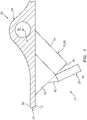
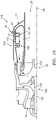
- FIG. 1 illustrates a portion of an apparatus 20 for a turbine engine.
- This turbine engine apparatus 20 is configured as, or otherwise includes, a fuel injector assembly 22 for a combustor section of the turbine engine.
- the turbine engine apparatus 20 includes a fuel conduit 24, a fuel nozzle 25 (e.g., a single and/or central orifice fuel nozzle) and a fuel nozzle splash plate 26.
- the turbine engine apparatus 20 of FIG. 1 may also include an apparatus base 27, which apparatus base 27 may provide a structural support for the fuel conduit 24 and/or the fuel nozzle 25.
- the apparatus base 27 may be configured as any part of the turbine engine within the combustor section that is proximate the fuel injector assembly 22.
- the apparatus base 27 of FIG. 1 may be configured as a turbine engine case such as, but not limited to, a combustor section case, a diffuser case and/or a combustor wall.
- the fuel conduit 24 is configured as, or may be part of, a fuel supply for the fuel nozzle 25.
- the fuel conduit 24, for example, may be or may be part of a fuel supply tube, a fuel inlet manifold and/or a fuel distribution manifold.
- the fuel conduit 24 is arranged at and/or is connected to a first side 30 (e.g., an exterior and/or outer side) of the apparatus base 27.
- the fuel conduit 24 is configured with an internal fuel supply passage 32 formed by an internal aperture (e.g., a bore, channel, etc.) within the fuel conduit 24.
- the supply passage 32 and the associated aperture extend within and/or through the fuel conduit 24 along a (e.g., curved or straight) centerline 34 of the supply passage 32, which may also be a centerline of the fuel conduit 24.
- the fuel nozzle 25 is configured to receive fuel from the fuel conduit 24, and inject the received fuel into a plenum (e.g., a fluid passage 34 such as an air passage) at a distal end 36 (e.g., tip) of the fuel nozzle 25 to impinge against the splash plate 26.
- a plenum e.g., a fluid passage 34 such as an air passage
- the fuel nozzle 25 of FIG. 2 includes a nozzle body 38 and a nozzle passage 40; e.g., a fuel passage.
- the nozzle body 38 is arranged at and/or is connected to a second side 42 (e.g., an interior and/or inner side) of the apparatus base 27, where the base second side 42 is opposite the base first side 30.
- the nozzle body 38 of FIG. 2 includes a nozzle tube 44 and a nozzle support structure 46 (e.g., a web).
- a base end of the nozzle tube 44 is connected to the apparatus base 27.
- the nozzle tube 44 projects longitudinally out from the apparatus base 27 along a (e.g., straight or curved) longitudinal centerline 48 of the nozzle passage 40 and/or the nozzle tube 44 to the fuel nozzle distal end 36.
- the nozzle support structure 46 is connected to and extends between the apparatus base 27 and a (e.g., upstream) side of the nozzle tube 44.
- the nozzle support structure 46 structurally ties the nozzle tube 44 to the apparatus base 27 and may thereby support the nozzle tube 44 within the fluid passage 34.
- the nozzle support structure 46 may form a support gusset for the nozzle tube 44.
- An internal bore of the nozzle tube 44 at least partially (or completely) forms the nozzle passage 40.
- the nozzle passage 40 extends longitudinally along the longitudinal centerline 48 within and/or through the apparatus base 27 and the nozzle tube 44 from the supply passage 32 to a downstream nozzle orifice 50 at the fuel nozzle distal end 36.
- This nozzle orifice 50 provides an outlet from the nozzle passage 40 and, more generally, the fuel nozzle 25.
- the nozzle passage 40 includes one or more different flow portions (e.g., 52-54) arranged longitudinally along the longitudinal centerline 48.
- the nozzle passage 40 of FIG. 3 for example, includes a (e.g., upstream) flow channel portion 52, a (e.g., intermediate) convergent portion 53 and a (e.g., downstream) throat portion 54.
- the flow channel portion 52 is upstream of the convergent portion 53, for example at (e.g., on, adjacent or proximate) an upstream end of the nozzle passage 40.
- the flow channel portion 52 of FIG. 3 is formed by a (e.g., non-tapering, cylindrical) flow channel sidewall surface 56. This flow channel sidewall surface 56 and, thus, the flow channel portion 52 extends longitudinally along the longitudinal centerline 48 from the supply passage 32 to the convergent portion 53.
- the convergent portion 53 is fluidly coupled between the flow channel portion 52 and the throat portion 54.
- the convergent portion 53 of FIG. 3 is formed by a tapering (e.g., frustoconical) convergent sidewall surface 58.
- This convergent sidewall surface 58 and, thus, the convergent portion 53 extends longitudinally along the longitudinal centerline 48 from the flow channel portion 52 to the throat portion 54, where a width 60 (e.g., diameter) of the convergent sidewall surface 58 decreases as the convergent portion 53 extends longitudinally towards the throat portion 54 / the nozzle orifice 50.
- the throat portion 54 is downstream of the convergent portion 53 and/or at the nozzle orifice 50, for example at (e.g., on, adjacent or proximate) the fuel nozzle distal end 36.
- the throat portion 54 of FIG. 3 is formed by a (e.g., non-tapering, cylindrical) throat sidewall surface 62. This throat sidewall surface 62 and, thus, the throat portion 54 extends longitudinally along the longitudinal centerline 48 from the convergent portion 53 to (or towards) the nozzle orifice 50. A downstream most end of the throat portion 54 may thereby define the nozzle orifice 50.
- the nozzle passage 40 may also include another flow portion (e.g., a divergent portion) arranged longitudinally between the throat portion 54 and the nozzle orifice 50.
- another flow portion e.g., a divergent portion
- any one or more of the foregoing flow portions 52-54 may also or alternatively be omitted; e.g., the flow channel portion 52 may be omitted where, for example, the convergent portion 53 extends from the supply passage 32 to the throat portion 54.
- the present disclosure therefore is not limited to the foregoing exemplary nozzle passage configurations.
- the splash plate 26 is configured to redirect (e.g., disperse) the fuel injected into the fluid passage 34 from the fuel nozzle 25 into a disperse (e.g., a widespread) pattern (e.g., see FIGS. 7 and 8 ).
- the splash plate 26, for example, is arranged proximate and laterally overlaps the nozzle orifice 50.
- the splash plate 26 is longitudinally spaced from the fuel nozzle 25 and its nozzle orifice 50 by a longitudinal distance 64 along the longitudinal centerline 48. This longitudinal distance 64 may be equal to or different (e.g., greater or less) than a width (e.g., diameter) of the nozzle passage 40.
- the present disclosure is not limited to the foregoing exemplary dimensional relationship between the splash plate 26 and the fuel nozzle 25.
- the splash plate 26 of FIGS. 4 and 5 is configured with a (e.g., circular) puck-like body.
- the splash plate 26 of FIG. 4 extends axially along a centerline axis 68 of the splash plate 26 between a frontside splash plate surface 70 and a backside splash plate surface 72, which backside splash plate surface 72 is axially opposite the frontside splash plate surface 70.
- Each of these splash plate surfaces 70 and 72 may have a generally circular shape. However, in other embodiments, one or more of the splash plate surfaces 70 and 72 may each have a non-circular (e.g., oval, polygonal, etc.) shape.
- Each of the splash plate surfaces 70 and 72 may be configured as a smooth and/or planar surface.
- one or more of the splash plate surfaces 70 and 72 may each be configured as a non-planar (e.g., concave, convex, etc.) surface and/or with one or more flow disruptions; e.g., apertures or projections.
- the splash plate 26 of FIGS. 4 and 5 also includes at least one side perimeter surface 74 that extends axially between the opposing splash plate surfaces 70 and 72 and circumferentially about the centerline axis 68 of the splash plate 26.
- the splash plate 26 and, more particularly, its frontside splash plate surface 70 is angularly offset from the longitudinal centerline 48 and/or fuel trajectory 90 (discussed below) by a first acute angle 76 (an angle that is greater than zero degrees and less than ninety degrees) when viewed, for example, in the plane of FIG. 4 ; e.g., a plane that laterally bisects one or more or each of the components 26, 44 and 46 and/or is parallel with and coincident with the centerline 48.
- the first acute angle 76 may be between sixty degrees (60°) and eighty degrees (80°) as shown in FIG.
- the first acute angle 76 may be substantially (e.g., +/- 2°) or exactly equal to seventy degrees (70°).
- the first acute angle 76 may be between thirty-five degrees (35°) and fifty-five degrees (55°) as shown in FIG. 6 ; e.g., the first acute angle 76 may be substantially (e.g., +/- 2°) or exactly equal to forty-five degrees (45°).
- the splash plate 26 of FIG. 4 and, more particularly, its frontside splash plate surface 70 is angularly offset from a plane of the nozzle orifice 50 and/or a surface 78 of the nozzle tube 44 at the fuel nozzle distal end 36 by a second acute angle 80.
- the second acute angle 80 may be between ten degrees (10°) and thirty degrees (30°) as shown in FIG. 4 ; e.g., the second acute angle 80 may be substantially (e.g., +/- 2°) or exactly equal to twenty degrees (20°). In another example, the second acute angle 80 may be between thirty-five degrees (35°) and fifty-five degrees (55°) as shown in FIG. 6 ; e.g., the second acute angle 80 may be substantially (e.g., +/- 2°) or exactly equal to forty-five degrees (45°).
- the splash plate 26 of FIGS. 4 and 5 is connected to the fuel nozzle 25 by at least (or only) one support member 82.
- the support member 82 may be configured as a beam and/or a pylon.
- the support member 82 of FIGS. 4 and 5 for example, has an elongated body that is connected to and extends between the fuel nozzle 25 and the splash plate 26. More particularly, the support member 82 of FIGS. 4 and 5 is connected (e.g., directly) to and extends between the nozzle support structure 46 and the splash plate 26.
- the support member 82 may also or alternatively be connected to and/or project out from the nozzle tube 44.
- the support member 82 of FIG. 4 is arranged at (e.g., on, adjacent or proximate) an upstream end 84 of the splash plate 26 relative to a fluid flow 85 (e.g., an air flow) within the fluid passage 34 (e.g., an air passage).
- the support member 82 may thereby be arranged upstream of the nozzle orifice 50 relative to the fluid flow 85 within the fluid passage 34.
- the fuel redirected (e.g., dispersed) by the splash plate 26 may flow unobstructed in a downstream direction through a spatial gap 86 between the splash plate 26 and the fuel nozzle 25.
- the present disclosure is not limited to such an exemplary support member placement.
- fuel is directed into the supply passage 32 from a fuel source (not shown). At least a portion (or all) of the fuel within the supply passage 32 is directed into the nozzle passage 40. Referring to FIG. 7 , this fuel flows through the nozzle passage 40 and out of the fuel nozzle 25 through the nozzle orifice 50 and into the fluid passage 34 (more particularly, into the spatial gap 86) as a fuel jet 88 along a fuel jet trajectory 90, which may be parallel (e.g., coaxial) with the centerline 48.
- This fuel jet 88 may be a linear concentrated flow / stream of fuel versus, for example, a spread-out pattern of fuel such as a conical film of fuel.
- the fuel jet 88 flows through the spatial gap 86 along its trajectory 90 and impacts (e.g., impinges against) the frontside splash plate surface 70 at a target area; e.g., an impingement area.
- a target area e.g., an impingement area.
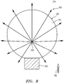
- the splash plate 26 redirects (e.g., disperses) the impinging fuel jet 88 radially outward (relative to the fuel jet trajectory 90) into a (e.g., uniform and/or symmetrical) disperse radiant pattern 92 (e.g., an arcuate and/or a generally planar film; schematically shown in FIGS. 7 and 8 via discrete flow arrows).
- a disperse radiant pattern 92 e.g., an arcuate and/or a generally planar film; schematically shown in FIGS. 7 and 8 via discrete flow arrows.
- the fuel may thereby be more evenly dispersed / spread / mixed into the fluid (e.g., air) flowing past the fuel nozzle 25 and the splash plate 26 within the fluid passage 34. Providing such relatively even mixing of the fuel and the fluid may in turn increase fuel burn efficiency and/or reduce likelihood of carbon formation within the turbine engine.
- the fluid e.g., air
- the splash plate 26 is cantilevered from the fuel nozzle 25 through the support member 82.
- the splash plate 26 may be further supported by at least one additional support member 82B as shown, for example, in FIGS. 9 and 10 .
- This downstream support member 82B is connected to and extends between the fuel nozzle 25 and the splash plate 26. More particularly, the downstream support member 82B of FIG. 9 is connected to and projects out from the nozzle tube 44.
- the downstream support member 82B of FIG. 10 is connected to and projects out from another (e.g., downstream) nozzle support structure 46B (e.g., web) for the fuel nozzle 25.
- the downstream support member 82B may be positioned opposite to (e.g., diametrically opposed with) the upstream support member 82; however, the present disclosure is not limited to such exemplary support member locations.
- including more than one support member may also provide for reducing the size of the support member (e.g., 82, 82B) e.g., thickness. Reducing the size of the support member(s) (e.g., 82, 82B) may in turn reduce flow impedance to the dispersed fuel traveling past the support members (e.g., 82, 82B) and, thus, promote further mixing between the fuel and the fluid flow; e.g., air flow.
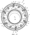
- the fuel nozzle 25 may be one of a plurality of fuel nozzles 25 connected to the apparatus base 27 and fluidly coupled with the fuel conduit 24. These fuel nozzles 25 may be arranged circumferentially about a centerline / rotational axis 94 of the turbine engine in an annular array. Each of the fuel nozzles 25 may be associated with a respective splash plate 26.
- the apparatus base 27, the fuel conduit 24 and each fuel nozzle 25 may be configured together in an integral, monolithic body.
- Each fuel nozzle 25 and its respective splash plate 26 may also or alternatively be configured together in the monolithic body.
- selecting the first acute angle 76 of FIG. 4 to be between sixty degrees and eighty degrees (e.g., approximately or exactly seventy degrees) and/or the second acute angle 80 to be between ten degrees and thirty degrees (e.g., approximately or exactly twenty degrees) may facilitate additive manufacturing of the turbine engine apparatus 20 as a monolithic body.
- the present disclosure is not limited to such an exemplary construction.
- one or more or each of the apparatus components and/or portions thereof may be individually formed and subsequently connected (e.g., fastener and/or bonded) together.
- the turbine engine apparatus 20 may also include one or more fuel vaporizers 96.
- Each fuel nozzle 25 is arranged with a respective one of the fuel vaporizers 96. More particularly, each fuel nozzle 25 projects into a respective one of the fuel vaporizers 96 and the associated splash plate 26 is arranged within a fluid passage (e.g., an air passage) of the respective fuel vaporizer 96. With such an arrangement, each splash plate 26 may direct a portion of the dispersed fuel to impinge against a surface 98 of the respective fuel vaporizer 96.
- the fuel vaporizer 96 may provide initial or further vaporization of the dispersed fuel.
- Each splash plate 26 may also direct another portion of the dispersed fuel to mix with the passing fluid (e.g., air) without impinging against the fuel vaporizer 96.
- the ratio of an amount of the dispersed fuel which contacts the fuel vaporizer 96 versus an amount of the dispersed fuel which does not contact the fuel vaporizer 96 may be controlled by adjusting a value of the first acute angle 76 of FIGS. 4 and 6 .
- a value of the first acute angle 76 of FIGS. 4 and 6 For example, when the value of the first acute angle 76 is increased towards ninety degrees (e.g., see FIG. 4 ), more of the fuel dispersed by the splash plate 26 may penetrate further into the fluid flow and, thus, more of the dispersed fuel may contact the fuel vaporizer 96 (see FIG. 12 ).
- the value of the first acute angle 76 is decreased towards zero degrees (e.g., see FIG. 6 )
- less of the fuel dispersed by the splash plate 26 may penetrate far into the fluid flow and, thus, less of the dispersed fuel may contact the fuel vaporizer 96 (see FIG. 12 ).
- each fuel vaporizer 96 is configured as a structure such as a flow tube 100 (e.g., a fluid tube, an air tube) for a combustor 102 in the combustor section 104.
- the combustor 102 may also include at least one flow tube 106 in between, for example, each circumferentially neighboring set of the vaporizers 96 and/or one or more flow tubes 108 in another (e.g., forward / upstream) array.
- Each of the flow tubes 100, 106, 108 is connected to and projects out from a wall 110 of the combustor 102 and into a combustion chamber 112 at least partially defined by the combustor wall 110.
- the fluid passage 34 (e.g., air passage) of each flow tube 100 is configured to receive fluid and, more particularly, compressed air from a compressor section of the turbine engine (not visible in FIGS. 11 and 12 ) through another plenum 114. This compressed air is directed through the respective fluid passage 34 and into the combustion chamber 112. However, before reaching the combustion chamber 112, the air within the respective fluid passage 34 is mixed with fuel dispersed from a respective one of the splash plates 26 to provide a mixture of compressed air and atomized fuel.
- the fuel By dispersing the fuel within the flow tube 100, the fuel may be more likely to atomize within the respective fluid passage 34; e.g., upon dispersing into the airflow and/or upon impinging against the surface 98 (e.g., an inner side wall surface of the flow tube 100).
- the fuel injector assembly 22 may reduce the likelihood of carbon buildup within the fluid passage 34 and/or within the combustion chamber 112.
- each fuel vaporizer 96 / flow tube 100 is configured to direct an axial fluid flow therewith / therethrough.
- the term axial fluid flow may describe a straight or linear flow of fluid such as a non-swirled fluid flow; e.g., non-swirled air.
- none of the fuel vaporizers 96 / flow tubes 100 is configured with or otherwise receives its fluid (e.g., air) directly and/or indirectly from a swirler.
- the fluid flowing through each fuel vaporizer 96 / flow tube 100 is non-swirled; e.g., the fluid primarily (or only) has axial velocity / momentum components with little or no tangential velocity / momentum components.
- each fuel vaporizer 96 / flow tube 100 may include relatively low level flow disruptions, turbulence, vortices, etc. caused when, for example, the fluid turns from the plenum 114 into the fluid passage 34, etc.
- FIG. 13 illustrates one such type and configuration of the turbine engine - a single spool, radial-flow turbojet turbine engine 116 configured for propelling an unmanned aerial vehicle (UAV), a drone, or any other manned or unmanned aircraft or self-propelled projectile.
- the turbine engine 116 includes an upstream inlet 118, a (e.g., radial) compressor section 120, the combustor section 104, a (e.g., radial) turbine section 122 and a downstream exhaust 124 fluidly coupled in series.
- a compressor rotor 126 in the compressor section 120 is coupled with a turbine rotor 128 in the turbine section 122 by a shaft 130, which rotates about the centerline / rotational axis 94 of the turbine engine 116.
- the turbine engine apparatus 20 may be included in various turbine engines other than the one described above.
- the turbine engine apparatus 20, for example, may be included in a geared turbine engine where a gear train connects one or more shafts to one or more rotors in a fan section, a compressor section and/or any other engine section.
- the turbine engine apparatus 20 may be included in a turbine engine configured without a gear train.
- the turbine engine apparatus 20 may be included in a geared or non-geared turbine engine configured with a single spool (e.g., see FIG. 13 ), with two spools, or with more than two spools.
- the turbine engine may be configured as a turbofan engine, a turbojet engine, a propfan engine, a pusher fan engine or any other type of turbine engine.
- the present disclosure therefore is not limited to any particular types or configurations of turbine engines.
- the present disclosure is also not limited to a propulsion system application.
- the gas turbine engine may alternatively be configured as an auxiliary power unit (APU) or an industrial gas turbine engine.
- APU auxiliary power unit
Abstract
Description
- This disclosure relates generally to a turbine engine and, more particularly, to a fuel injector assembly for the turbine engine.
- A combustor section in a modern a turbine engine includes one or more fuel injectors. Each fuel injector is operable to inject fuel for combustion within a combustion chamber. Various types and configurations of fuel injectors are known in the art. While these known fuel injectors have various benefits, there is still room in the art for improvement. There is a need in the art, for example, for fuel injectors with reduced manufacturing costs, that facilitate reduced assembly time as well as that reduce likelihood of carbon buildup within the combustion chamber caused by solidification of and/or traces of non-combusted fuel.
- According to an aspect of the present disclosure, an apparatus is provided for a turbine engine. This turbine engine apparatus includes a monolithic body. The monolithic body includes a splash plate and a fuel nozzle. The splash plate includes a splash plate surface. The fuel nozzle includes a nozzle orifice. The fuel nozzle is configured to direct fuel out of the nozzle orifice to impinge against the splash plate surface.
- According to another aspect of the present disclosure, another apparatus is provided for a turbine engine. This turbine engine apparatus includes a structure, a fuel nozzle and a splash plate. The structure includes a fluid passage. The structure is configured to direct an axial fluid flow through the fluid passage. The fuel nozzle includes a nozzle orifice. The splash plate is arranged within the fluid passage and includes a splash plate surface. The fuel nozzle is configured to direct fuel out of the nozzle orifice to impinge against the splash plate surface. The splash plate is configured to disperse the fuel that impinges against the splash plate surface into the axial fluid flow.
- According to still another aspect of the present disclosure, another apparatus is provided for a turbine engine. This turbine engine apparatus includes a fuel nozzle and a splash plate. The fuel nozzle includes a nozzle orifice. The splash plate includes a splash plate surface spaced from the fuel nozzle. The fuel nozzle is configured to direct a fuel jet out of the nozzle orifice along a fuel jet trajectory to the splash plate surface. The splash plate is configured to disperse fuel from the fuel jet in a radial outward pattern. The splash plate surface is angularly offset from the fuel jet trajectory by an acute angle.
- The axial fluid flow may be or otherwise include a non-swirled fluid flow.
- The splash plate may be integral with the fuel nozzle.
- The splash plate may be configured with the fuel nozzle in a monolithic body.
- The turbine engine assembly may also include a structure that includes an air passage. The structure may be configured to direct air through the air passage. The splash plate may be configured to disperse the fuel from the fuel jet in the radial outward pattern into the air within the air passage.
- The fuel nozzle may be configured to direct the fuel out of the nozzle orifice as a fuel jet. The splash plate may be configured to redirect the fuel jet into a radiant pattern of fuel.
- The splash plate may be spaced from and/or may overlap the nozzle orifice.
- The splash plate surface may be configured as or otherwise include a planar splash plate surface.
- The fuel nozzle may be configured to direct the fuel out of the nozzle orifice along a trajectory to impinge against the splash plate surface. The splash plate surface may be angularly offset from the trajectory by an acute angle.
- The acute angle may be between sixty degrees (60°) and eighty degrees (80°).
- The acute angle may be between thirty-five degrees (35°) and fifty-five degrees (55°).
- The turbine engine assembly may also include a support member connecting and extending between the splash plate and the fuel nozzle.
- The fuel nozzle may project into a flow passage. The support member may be upstream of the nozzle orifice relative to a fluid flow within the flow passage.
- The turbine engine assembly may also include a second support member connecting and extending between the splash plate and the fuel nozzle.
- The fuel nozzle may include a nozzle tube that has and extends along a longitudinal centerline. The nozzle orifice may be coaxial with the longitudinal centerline.
- The turbine engine assembly may also include a fuel vaporizer. The splash plate may be configured to direct at least some of the dispersed fuel against the fuel vaporizer.
- The turbine engine assembly may also include an air tube that includes an air passage. The fuel nozzle may project into the air passage. The splash plate may be arranged within the air passage such that the splash plate is configured to direct at least some of the dispersed fuel against an inner sidewall surface of the air tube.
- The turbine engine assembly may also include a combustor wall at least partially forming a combustion chamber. The air tube may be connected to the combustor wall and/or may project into the combustion chamber.
- The present disclosure may include any one or more of the individual features disclosed above and/or below alone or in any combination thereof.
- The foregoing features and the operation of the invention will become more apparent in light of the following description and the accompanying drawings.
-
-
FIGS. 1-4 are side sectional illustrations of portions of a turbine engine apparatus. -
FIG. 5 is a perspective cross-sectional illustration of another portion of the turbine engine apparatus. -
FIG. 6 is a side sectional illustration of another portion of the turbine engine apparatus. -
FIG. 7 is a side cutaway illustration of another portion of the turbine engine apparatus schematically depicting an air flow and a fuel flow. -
FIG. 8 is an illustration of a splash plate and a section of an associated support member further schematically depicting the fuel flow. -
FIGS. 9 and 10 are perspective illustrations of the turbine engine apparatus configured with an additional support member for each splash plate. -
FIG. 11 is a perspective cross-sectional illustration of a portion of a combustor section. -
FIG. 12 is a perspective side sectional illustration of another portion of the combustor section. -
FIG. 13 is a schematic side illustration of a single spool, radial-flow turbojet turbine engine. -
FIG. 1 illustrates a portion of anapparatus 20 for a turbine engine. Thisturbine engine apparatus 20 is configured as, or otherwise includes, afuel injector assembly 22 for a combustor section of the turbine engine. Theturbine engine apparatus 20 includes afuel conduit 24, a fuel nozzle 25 (e.g., a single and/or central orifice fuel nozzle) and a fuelnozzle splash plate 26. Theturbine engine apparatus 20 ofFIG. 1 may also include anapparatus base 27, whichapparatus base 27 may provide a structural support for thefuel conduit 24 and/or thefuel nozzle 25. - The
apparatus base 27 may be configured as any part of the turbine engine within the combustor section that is proximate thefuel injector assembly 22. Theapparatus base 27 ofFIG. 1 , for example, may be configured as a turbine engine case such as, but not limited to, a combustor section case, a diffuser case and/or a combustor wall. - The
fuel conduit 24 is configured as, or may be part of, a fuel supply for thefuel nozzle 25. Thefuel conduit 24, for example, may be or may be part of a fuel supply tube, a fuel inlet manifold and/or a fuel distribution manifold. Thefuel conduit 24 is arranged at and/or is connected to a first side 30 (e.g., an exterior and/or outer side) of theapparatus base 27. Thefuel conduit 24 is configured with an internalfuel supply passage 32 formed by an internal aperture (e.g., a bore, channel, etc.) within thefuel conduit 24. Thesupply passage 32 and the associated aperture extend within and/or through thefuel conduit 24 along a (e.g., curved or straight) centerline 34 of thesupply passage 32, which may also be a centerline of thefuel conduit 24. - Referring to
FIG. 2 , thefuel nozzle 25 is configured to receive fuel from thefuel conduit 24, and inject the received fuel into a plenum (e.g., afluid passage 34 such as an air passage) at a distal end 36 (e.g., tip) of thefuel nozzle 25 to impinge against thesplash plate 26. Thefuel nozzle 25 ofFIG. 2 includes a nozzle body 38 and anozzle passage 40; e.g., a fuel passage. - The nozzle body 38 is arranged at and/or is connected to a second side 42 (e.g., an interior and/or inner side) of the
apparatus base 27, where the basesecond side 42 is opposite the basefirst side 30. The nozzle body 38 ofFIG. 2 includes anozzle tube 44 and a nozzle support structure 46 (e.g., a web). A base end of thenozzle tube 44 is connected to theapparatus base 27. Thenozzle tube 44 projects longitudinally out from theapparatus base 27 along a (e.g., straight or curved)longitudinal centerline 48 of thenozzle passage 40 and/or thenozzle tube 44 to the fuel nozzledistal end 36. Thenozzle support structure 46 is connected to and extends between theapparatus base 27 and a (e.g., upstream) side of thenozzle tube 44. Thenozzle support structure 46 structurally ties thenozzle tube 44 to theapparatus base 27 and may thereby support thenozzle tube 44 within thefluid passage 34. Thenozzle support structure 46, for example, may form a support gusset for thenozzle tube 44. - An internal bore of the
nozzle tube 44 at least partially (or completely) forms thenozzle passage 40. Thenozzle passage 40 extends longitudinally along thelongitudinal centerline 48 within and/or through theapparatus base 27 and thenozzle tube 44 from thesupply passage 32 to adownstream nozzle orifice 50 at the fuel nozzledistal end 36. Thisnozzle orifice 50 provides an outlet from thenozzle passage 40 and, more generally, thefuel nozzle 25. - Referring to
FIG. 3 , thenozzle passage 40 includes one or more different flow portions (e.g., 52-54) arranged longitudinally along thelongitudinal centerline 48. Thenozzle passage 40 ofFIG. 3 , for example, includes a (e.g., upstream)flow channel portion 52, a (e.g., intermediate)convergent portion 53 and a (e.g., downstream)throat portion 54. - The
flow channel portion 52 is upstream of theconvergent portion 53, for example at (e.g., on, adjacent or proximate) an upstream end of thenozzle passage 40. Theflow channel portion 52 ofFIG. 3 , for example, is formed by a (e.g., non-tapering, cylindrical) flowchannel sidewall surface 56. This flowchannel sidewall surface 56 and, thus, theflow channel portion 52 extends longitudinally along thelongitudinal centerline 48 from thesupply passage 32 to theconvergent portion 53. - The
convergent portion 53 is fluidly coupled between theflow channel portion 52 and thethroat portion 54. Theconvergent portion 53 ofFIG. 3 , for example, is formed by a tapering (e.g., frustoconical)convergent sidewall surface 58. Thisconvergent sidewall surface 58 and, thus, theconvergent portion 53 extends longitudinally along thelongitudinal centerline 48 from theflow channel portion 52 to thethroat portion 54, where a width 60 (e.g., diameter) of theconvergent sidewall surface 58 decreases as theconvergent portion 53 extends longitudinally towards thethroat portion 54 / thenozzle orifice 50. - The
throat portion 54 is downstream of theconvergent portion 53 and/or at thenozzle orifice 50, for example at (e.g., on, adjacent or proximate) the fuel nozzledistal end 36. Thethroat portion 54 ofFIG. 3 , for example, is formed by a (e.g., non-tapering, cylindrical)throat sidewall surface 62. Thisthroat sidewall surface 62 and, thus, thethroat portion 54 extends longitudinally along thelongitudinal centerline 48 from theconvergent portion 53 to (or towards) thenozzle orifice 50. A downstream most end of thethroat portion 54 may thereby define thenozzle orifice 50. Of course, in other embodiments, thenozzle passage 40 may also include another flow portion (e.g., a divergent portion) arranged longitudinally between thethroat portion 54 and thenozzle orifice 50. In still other embodiments, any one or more of the foregoing flow portions 52-54 may also or alternatively be omitted; e.g., theflow channel portion 52 may be omitted where, for example, theconvergent portion 53 extends from thesupply passage 32 to thethroat portion 54. The present disclosure therefore is not limited to the foregoing exemplary nozzle passage configurations. - Referring to
FIG. 4 , thesplash plate 26 is configured to redirect (e.g., disperse) the fuel injected into thefluid passage 34 from thefuel nozzle 25 into a disperse (e.g., a widespread) pattern (e.g., seeFIGS. 7 and8 ). Thesplash plate 26, for example, is arranged proximate and laterally overlaps thenozzle orifice 50. Thesplash plate 26 is longitudinally spaced from thefuel nozzle 25 and itsnozzle orifice 50 by alongitudinal distance 64 along thelongitudinal centerline 48. Thislongitudinal distance 64 may be equal to or different (e.g., greater or less) than a width (e.g., diameter) of thenozzle passage 40. Thelongitudinal distance 64 ofFIG. 4 , for example, is between one-half times (0.5x) and five times (5x) a width 66 (e.g., a diameter) of thethroat portion 54. The present disclosure, however, is not limited to the foregoing exemplary dimensional relationship between thesplash plate 26 and thefuel nozzle 25. - The
splash plate 26 ofFIGS. 4 and5 is configured with a (e.g., circular) puck-like body. Thesplash plate 26 ofFIG. 4 , for example, extends axially along acenterline axis 68 of thesplash plate 26 between a frontsidesplash plate surface 70 and a backsidesplash plate surface 72, which backsidesplash plate surface 72 is axially opposite the frontsidesplash plate surface 70. Each of these splash plate surfaces 70 and 72 may have a generally circular shape. However, in other embodiments, one or more of the splash plate surfaces 70 and 72 may each have a non-circular (e.g., oval, polygonal, etc.) shape. Each of the splash plate surfaces 70 and 72 may be configured as a smooth and/or planar surface. However, in other embodiments, one or more of the splash plate surfaces 70 and 72 may each be configured as a non-planar (e.g., concave, convex, etc.) surface and/or with one or more flow disruptions; e.g., apertures or projections. Thesplash plate 26 ofFIGS. 4 and5 also includes at least oneside perimeter surface 74 that extends axially between the opposing splash plate surfaces 70 and 72 and circumferentially about thecenterline axis 68 of thesplash plate 26. - Referring to
FIG. 4 , thesplash plate 26 and, more particularly, its frontsidesplash plate surface 70 is angularly offset from thelongitudinal centerline 48 and/or fuel trajectory 90 (discussed below) by a first acute angle 76 (an angle that is greater than zero degrees and less than ninety degrees) when viewed, for example, in the plane ofFIG. 4 ; e.g., a plane that laterally bisects one or more or each of thecomponents centerline 48. The firstacute angle 76 may be between sixty degrees (60°) and eighty degrees (80°) as shown inFIG. 4 ; e.g., the firstacute angle 76 may be substantially (e.g., +/- 2°) or exactly equal to seventy degrees (70°). In another example, the firstacute angle 76 may be between thirty-five degrees (35°) and fifty-five degrees (55°) as shown inFIG. 6 ; e.g., the firstacute angle 76 may be substantially (e.g., +/- 2°) or exactly equal to forty-five degrees (45°). - The
splash plate 26 ofFIG. 4 and, more particularly, its frontsidesplash plate surface 70 is angularly offset from a plane of thenozzle orifice 50 and/or asurface 78 of thenozzle tube 44 at the fuel nozzledistal end 36 by a secondacute angle 80. The secondacute angle 80 may be between ten degrees (10°) and thirty degrees (30°) as shown inFIG. 4 ; e.g., the secondacute angle 80 may be substantially (e.g., +/- 2°) or exactly equal to twenty degrees (20°). In another example, the secondacute angle 80 may be between thirty-five degrees (35°) and fifty-five degrees (55°) as shown inFIG. 6 ; e.g., the secondacute angle 80 may be substantially (e.g., +/- 2°) or exactly equal to forty-five degrees (45°). - The
splash plate 26 ofFIGS. 4 and5 is connected to thefuel nozzle 25 by at least (or only) onesupport member 82. Thesupport member 82 may be configured as a beam and/or a pylon. Thesupport member 82 ofFIGS. 4 and5 , for example, has an elongated body that is connected to and extends between thefuel nozzle 25 and thesplash plate 26. More particularly, thesupport member 82 ofFIGS. 4 and5 is connected (e.g., directly) to and extends between thenozzle support structure 46 and thesplash plate 26. Of course, in other embodiments, thesupport member 82 may also or alternatively be connected to and/or project out from thenozzle tube 44. - The
support member 82 ofFIG. 4 is arranged at (e.g., on, adjacent or proximate) anupstream end 84 of thesplash plate 26 relative to a fluid flow 85 (e.g., an air flow) within the fluid passage 34 (e.g., an air passage). Thesupport member 82 may thereby be arranged upstream of thenozzle orifice 50 relative to thefluid flow 85 within thefluid passage 34. With such an arrangement, the fuel redirected (e.g., dispersed) by thesplash plate 26 may flow unobstructed in a downstream direction through aspatial gap 86 between thesplash plate 26 and thefuel nozzle 25. The present disclosure, however, is not limited to such an exemplary support member placement. - Referring to
FIG. 2 , during turbine engine operation, fuel is directed into thesupply passage 32 from a fuel source (not shown). At least a portion (or all) of the fuel within thesupply passage 32 is directed into thenozzle passage 40. Referring toFIG. 7 , this fuel flows through thenozzle passage 40 and out of thefuel nozzle 25 through thenozzle orifice 50 and into the fluid passage 34 (more particularly, into the spatial gap 86) as afuel jet 88 along afuel jet trajectory 90, which may be parallel (e.g., coaxial) with thecenterline 48. Thisfuel jet 88 may be a linear concentrated flow / stream of fuel versus, for example, a spread-out pattern of fuel such as a conical film of fuel. Thefuel jet 88 flows through thespatial gap 86 along itstrajectory 90 and impacts (e.g., impinges against) the frontsidesplash plate surface 70 at a target area; e.g., an impingement area. Referring toFIGS. 7 and8 , upon impacting the frontsidesplash plate surface 70, thesplash plate 26 redirects (e.g., disperses) the impingingfuel jet 88 radially outward (relative to the fuel jet trajectory 90) into a (e.g., uniform and/or symmetrical) disperse radiant pattern 92 (e.g., an arcuate and/or a generally planar film; schematically shown inFIGS. 7 and8 via discrete flow arrows). The fuel may thereby be more evenly dispersed / spread / mixed into the fluid (e.g., air) flowing past thefuel nozzle 25 and thesplash plate 26 within thefluid passage 34. Providing such relatively even mixing of the fuel and the fluid may in turn increase fuel burn efficiency and/or reduce likelihood of carbon formation within the turbine engine. - In some embodiments, referring to
FIG. 2 , thesplash plate 26 is cantilevered from thefuel nozzle 25 through thesupport member 82. In other embodiments, thesplash plate 26 may be further supported by at least oneadditional support member 82B as shown, for example, inFIGS. 9 and 10 . Thisdownstream support member 82B is connected to and extends between thefuel nozzle 25 and thesplash plate 26. More particularly, thedownstream support member 82B ofFIG. 9 is connected to and projects out from thenozzle tube 44. Thedownstream support member 82B ofFIG. 10 is connected to and projects out from another (e.g., downstream)nozzle support structure 46B (e.g., web) for thefuel nozzle 25. Referring toFIGS. 9 and 10 , thedownstream support member 82B may be positioned opposite to (e.g., diametrically opposed with) theupstream support member 82; however, the present disclosure is not limited to such exemplary support member locations. - In addition to increasing structural ties between the
splash plate 26 and thefuel nozzle 25, including more than one support member (e.g., 82, 82B) may also provide for reducing the size of the support member (e.g., 82, 82B) e.g., thickness. Reducing the size of the support member(s) (e.g., 82, 82B) may in turn reduce flow impedance to the dispersed fuel traveling past the support members (e.g., 82, 82B) and, thus, promote further mixing between the fuel and the fluid flow; e.g., air flow. - In some embodiments, referring to
FIG. 11 , thefuel nozzle 25 may be one of a plurality offuel nozzles 25 connected to theapparatus base 27 and fluidly coupled with thefuel conduit 24. Thesefuel nozzles 25 may be arranged circumferentially about a centerline /rotational axis 94 of the turbine engine in an annular array. Each of thefuel nozzles 25 may be associated with arespective splash plate 26. - In some embodiments, referring to
FIG. 2 , theapparatus base 27, thefuel conduit 24 and eachfuel nozzle 25 may be configured together in an integral, monolithic body. Eachfuel nozzle 25 and itsrespective splash plate 26 may also or alternatively be configured together in the monolithic body. In such embodiments, selecting the firstacute angle 76 ofFIG. 4 to be between sixty degrees and eighty degrees (e.g., approximately or exactly seventy degrees) and/or the secondacute angle 80 to be between ten degrees and thirty degrees (e.g., approximately or exactly twenty degrees) may facilitate additive manufacturing of theturbine engine apparatus 20 as a monolithic body. The present disclosure, however, is not limited to such an exemplary construction. For example, in other embodiments, one or more or each of the apparatus components and/or portions thereof may be individually formed and subsequently connected (e.g., fastener and/or bonded) together. - In some embodiments, referring to
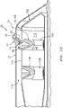
FIGS. 11 and12 , theturbine engine apparatus 20 may also include one or more fuel vaporizers 96. Eachfuel nozzle 25 is arranged with a respective one of the fuel vaporizers 96. More particularly, eachfuel nozzle 25 projects into a respective one of the fuel vaporizers 96 and the associatedsplash plate 26 is arranged within a fluid passage (e.g., an air passage) of the respective fuel vaporizer 96. With such an arrangement, eachsplash plate 26 may direct a portion of the dispersed fuel to impinge against asurface 98 of the respective fuel vaporizer 96. The fuel vaporizer 96 may provide initial or further vaporization of the dispersed fuel. Eachsplash plate 26 may also direct another portion of the dispersed fuel to mix with the passing fluid (e.g., air) without impinging against the fuel vaporizer 96. - The ratio of an amount of the dispersed fuel which contacts the fuel vaporizer 96 versus an amount of the dispersed fuel which does not contact the fuel vaporizer 96 may be controlled by adjusting a value of the first
acute angle 76 ofFIGS. 4 and6 . For example, when the value of the firstacute angle 76 is increased towards ninety degrees (e.g., seeFIG. 4 ), more of the fuel dispersed by thesplash plate 26 may penetrate further into the fluid flow and, thus, more of the dispersed fuel may contact the fuel vaporizer 96 (seeFIG. 12 ). By contrast, when the value of the firstacute angle 76 is decreased towards zero degrees (e.g., seeFIG. 6 ), less of the fuel dispersed by thesplash plate 26 may penetrate far into the fluid flow and, thus, less of the dispersed fuel may contact the fuel vaporizer 96 (seeFIG. 12 ). - In the specific embodiment of
FIGS. 11 and12 , each fuel vaporizer 96 is configured as a structure such as a flow tube 100 (e.g., a fluid tube, an air tube) for acombustor 102 in thecombustor section 104. Note, thecombustor 102 may also include at least oneflow tube 106 in between, for example, each circumferentially neighboring set of the vaporizers 96 and/or one ormore flow tubes 108 in another (e.g., forward / upstream) array. Each of theflow tubes wall 110 of thecombustor 102 and into acombustion chamber 112 at least partially defined by thecombustor wall 110. The fluid passage 34 (e.g., air passage) of each flow tube 100 is configured to receive fluid and, more particularly, compressed air from a compressor section of the turbine engine (not visible inFIGS. 11 and12 ) through anotherplenum 114. This compressed air is directed through therespective fluid passage 34 and into thecombustion chamber 112. However, before reaching thecombustion chamber 112, the air within therespective fluid passage 34 is mixed with fuel dispersed from a respective one of thesplash plates 26 to provide a mixture of compressed air and atomized fuel. By dispersing the fuel within the flow tube 100, the fuel may be more likely to atomize within therespective fluid passage 34; e.g., upon dispersing into the airflow and/or upon impinging against the surface 98 (e.g., an inner side wall surface of the flow tube 100). By increasing atomization of the fuel, thefuel injector assembly 22 may reduce the likelihood of carbon buildup within thefluid passage 34 and/or within thecombustion chamber 112. - In some embodiments, each fuel vaporizer 96 / flow tube 100 is configured to direct an axial fluid flow therewith / therethrough. The term axial fluid flow may describe a straight or linear flow of fluid such as a non-swirled fluid flow; e.g., non-swirled air. For example, none of the fuel vaporizers 96 / flow tubes 100 is configured with or otherwise receives its fluid (e.g., air) directly and/or indirectly from a swirler. Thus, the fluid flowing through each fuel vaporizer 96 / flow tube 100 is non-swirled; e.g., the fluid primarily (or only) has axial velocity / momentum components with little or no tangential velocity / momentum components. Of course, the fluid flowing through each fuel vaporizer 96 / flow tube 100 may include relatively low level flow disruptions, turbulence, vortices, etc. caused when, for example, the fluid turns from the
plenum 114 into thefluid passage 34, etc. - The
turbine engine apparatus 20 of the present disclosure may be configured with various different types and configurations of turbine engines.FIG. 13 illustrates one such type and configuration of the turbine engine - a single spool, radial-flowturbojet turbine engine 116 configured for propelling an unmanned aerial vehicle (UAV), a drone, or any other manned or unmanned aircraft or self-propelled projectile. In the specific embodiment ofFIG. 13 , theturbine engine 116 includes anupstream inlet 118, a (e.g., radial)compressor section 120, thecombustor section 104, a (e.g., radial)turbine section 122 and adownstream exhaust 124 fluidly coupled in series. Acompressor rotor 126 in thecompressor section 120 is coupled with aturbine rotor 128 in theturbine section 122 by ashaft 130, which rotates about the centerline /rotational axis 94 of theturbine engine 116. - The
turbine engine apparatus 20 may be included in various turbine engines other than the one described above. Theturbine engine apparatus 20, for example, may be included in a geared turbine engine where a gear train connects one or more shafts to one or more rotors in a fan section, a compressor section and/or any other engine section. Alternatively, theturbine engine apparatus 20 may be included in a turbine engine configured without a gear train. Theturbine engine apparatus 20 may be included in a geared or non-geared turbine engine configured with a single spool (e.g., seeFIG. 13 ), with two spools, or with more than two spools. The turbine engine may be configured as a turbofan engine, a turbojet engine, a propfan engine, a pusher fan engine or any other type of turbine engine. The present disclosure therefore is not limited to any particular types or configurations of turbine engines. The present disclosure is also not limited to a propulsion system application. For example, the gas turbine engine may alternatively be configured as an auxiliary power unit (APU) or an industrial gas turbine engine. - While various embodiments of the present disclosure have been described, it will be apparent to those of ordinary skill in the art that many more embodiments and implementations are possible within the scope of the disclosure. For example, the present disclosure as described herein includes several aspects and embodiments that include particular features. Although these features may be described individually, it is within the scope of the present disclosure that some or all of these features may be combined with any one of the aspects and remain within the scope of the disclosure. Accordingly, the present disclosure is not to be restricted except in light of the attached claims and their equivalents.
Claims (15)
- An apparatus (20) for a turbine engine (116), comprising a monolithic body including a splash plate (26) and a fuel nozzle (25), wherein:the splash plate (26) includes a splash plate surface (70);the fuel nozzle (25) includes a nozzle orifice (50); andthe fuel nozzle (25) is configured to direct fuel out of the nozzle orifice (50) to impinge against the splash plate surface (70).
- The apparatus (20) of claim 1, wherein:the fuel nozzle (25) is configured to direct the fuel out of the nozzle orifice (50) as a fuel jet (88); andthe splash plate (26) is configured to redirect the fuel jet (88) into a radiant pattern (92) of fuel.
- The apparatus (20) of claim 1 or 2, wherein the splash plate (26) is spaced from and overlaps the nozzle orifice (50).
- The apparatus (20) of any preceding claim, wherein the splash plate surface (70) comprises a planar splash plate surface (70).
- The apparatus (20) of any preceding claim, whereinthe fuel nozzle (25) is configured to direct the fuel out of the nozzle orifice (50) along a trajectory (90) to impinge against the splash plate surface (70); andthe splash plate surface (70) is angularly offset from the trajectory (90) by an acute angle (76).
- The apparatus (20) of claim 5, wherein the acute angle (76) is between sixty degrees and eighty degrees or between thirty-five degrees and fifty-five degrees.
- The apparatus (20) of any preceding claim, further comprising a support member (82) connecting and extending between the splash plate (26) and the fuel nozzle (25).
- The apparatus (20) of claim 7, wherein:the fuel nozzle (25) projects into a flow passage (34); andthe support member (82) is upstream of the nozzle orifice (50) relative to a fluid flow (85) within the flow passage (34).
- The apparatus (20) of claim 7 or 8, further comprising a second support member (82B) connecting and extending between the splash plate (26) and the fuel nozzle (25).
- The apparatus (20) of any preceding claim, wherein:the fuel nozzle (25) includes a nozzle tube (44) that has and extends along a longitudinal centerline (48); andthe nozzle orifice (50) is coaxial with the longitudinal centerline (48).
- The apparatus (20) of any preceding claim, further comprising a fuel vaporizer (96), wherein the splash plate (26) is configured to direct at least some of the dispersed fuel against the fuel vaporizer (96).
- The apparatus (20) of any preceding claim, further comprising an air tube (100) including an air passage, wherein:the fuel nozzle (25) projects into the air passage (34); andthe splash plate (26) is arranged within the air passage (34) such that the splash plate (26) is configured to direct at least some of the dispersed fuel against an inner sidewall surface (98) of the air tube (100),optionally, wherein the apparatus (20) further comprises a combustor wall (110) at least partially forming a combustion chamber (112), and wherein the air tube (100) is connected to the combustor wall (110) and projects into the combustion chamber (112).
- An apparatus (20) for a turbine engine (116), comprising:a structure including a fluid passage (34), the structure configured to direct an axial fluid flow (85) through the fluid passage (34);a fuel nozzle (25) including a nozzle orifice (50); anda splash plate (26) arranged within the fluid passage (34) and including a splash plate surface (70),wherein the fuel nozzle (25) is configured to direct fuel out of the nozzle orifice (50) to impinge against the splash plate surface (70), and the splash plate (26) is configured to disperse the fuel that impinges against the splash plate surface (70) into the axial fluid flow (85).
- The apparatus (20) of claim 13, wherein:the splash plate (26) is integral with the fuel nozzle (25); and/orthe fuel nozzle (25) is configured to direct the fuel out of the nozzle orifice (50) along a trajectory (90) to impinge against the splash plate surface (70) and the splash plate surface (70) is angularly offset from the trajectory (90) by an acute angle (76); and/orthe axial fluid flow (85) comprises a non-swirled fluid flow.
- An apparatus (20) for a turbine engine (116), comprising:a fuel nozzle (25) including a nozzle orifice (50); anda splash plate (26) including a splash plate surface (70) spaced from the fuel nozzle (25),wherein the fuel nozzle (25) is configured to direct a fuel jet (88) out of the nozzle orifice (50) along a fuel jet trajectory (90) to the splash plate surface (70), and the splash plate (26) is configured to disperse fuel from the fuel jet (88) in a radial outward pattern (92),wherein the splash plate surface (70) is angularly offset from the fuel jet trajectory (90) by an acute angle (76),wherein the splash plate (26) is optionally configured with the fuel nozzle (25) in a monolithic body.
Applications Claiming Priority (1)
| Application Number | Priority Date | Filing Date | Title |
|---|---|---|---|
| US17/108,606 US11649964B2 (en) | 2020-12-01 | 2020-12-01 | Fuel injector assembly for a turbine engine |
Publications (2)
| Publication Number | Publication Date |
|---|---|
| EP4008959A1 true EP4008959A1 (en) | 2022-06-08 |
| EP4008959B1 EP4008959B1 (en) | 2024-01-31 |
Family
ID=78820367
Family Applications (1)
| Application Number | Title | Priority Date | Filing Date |
|---|---|---|---|
| EP21211805.3A Active EP4008959B1 (en) | 2020-12-01 | 2021-12-01 | Apparatus for a turbine engine including a fuel splash plate |
Country Status (2)
| Country | Link |
|---|---|
| US (2) | US11649964B2 (en) |
| EP (1) | EP4008959B1 (en) |
Citations (4)
| Publication number | Priority date | Publication date | Assignee | Title |
|---|---|---|---|---|
| US4967562A (en) * | 1988-12-12 | 1990-11-06 | Sundstrand Corporation | Turbine engine with high efficiency fuel atomization |
| US4989404A (en) * | 1988-12-12 | 1991-02-05 | Sundstrand Corporation | Turbine engine with high efficiency fuel atomization |
| US5277022A (en) * | 1990-06-22 | 1994-01-11 | Sundstrand Corporation | Air blast fuel injecton system |
| US20160209041A1 (en) * | 2013-10-07 | 2016-07-21 | United Technologies Corporation | Fuel vaporizer for a turbine engine combustor |
Family Cites Families (61)
| Publication number | Priority date | Publication date | Assignee | Title |
|---|---|---|---|---|
| US1460470A (en) | 1922-05-22 | 1923-07-03 | Askins Joseph | Vaporizer and mixer for internal-combustion engines |
| US2385833A (en) | 1943-01-27 | 1945-10-02 | Kevork K Nahigyan | Fuel vaporizer for jet propulsion units |
| US2616258A (en) | 1946-01-09 | 1952-11-04 | Bendix Aviat Corp | Jet engine combustion apparatus, including pilot burner for ignition and vaporization of main fuel supply |
| US2727358A (en) | 1952-03-27 | 1955-12-20 | A V Roe Canada Ltd | Reverse-flow vaporizer with single inlet and plural outlets |
| US3153323A (en) | 1954-03-31 | 1964-10-20 | James R Hamm | Internal combustion apparatus |
| US3053461A (en) | 1959-11-12 | 1962-09-11 | Bruce D Inglis | Pressure controlled spray device |
| GB1136543A (en) | 1966-02-21 | 1968-12-11 | Rolls Royce | Liquid fuel combustion apparatus for gas turbine engines |
| US3603711A (en) | 1969-09-17 | 1971-09-07 | Edgar S Downs | Combination pressure atomizer and surface-type burner for liquid fuel |
| DE2038643A1 (en) | 1970-08-04 | 1972-02-10 | Bosch Gmbh Robert | Fuel injector |
| US3912164A (en) * | 1971-01-11 | 1975-10-14 | Parker Hannifin Corp | Method of liquid fuel injection, and to air blast atomizers |
| US3693354A (en) | 1971-01-22 | 1972-09-26 | Gen Electric | Aircraft engine fan duct burner system |
| US3777983A (en) | 1971-12-16 | 1973-12-11 | Gen Electric | Gas cooled dual fuel air atomized fuel nozzle |
| JPS5342897B2 (en) | 1972-11-09 | 1978-11-15 | ||
| DE2326680C3 (en) | 1973-05-25 | 1980-09-25 | Mtu Motoren- Und Turbinen-Union Muenchen Gmbh, 8000 Muenchen | Flame tube with premixing chamber for combustion chambers of gas turbine engines |
| US4081958A (en) | 1973-11-01 | 1978-04-04 | The Garrett Corporation | Low nitric oxide emission combustion system for gas turbines |
| US3915137A (en) | 1974-03-04 | 1975-10-28 | Hugh K Evans | Fuel vaporizer |
| GB1481617A (en) | 1974-10-07 | 1977-08-03 | Rolls Royce | Gas turbine fuel burners |
| US4134260A (en) | 1977-10-25 | 1979-01-16 | General Motors Corporation | Afterburner flow mixing means in turbofan jet engine |
| US4242863A (en) | 1978-03-16 | 1981-01-06 | Caterpillar Tractor Co. | Dual phase fuel vaporizing combustor |
| DE2836534C2 (en) | 1978-08-21 | 1982-09-02 | Oertli AG Dübendorf, Dübendorf | Process for burning liquid fuel and burners for carrying out the process |
| GB2036296B (en) | 1978-11-20 | 1982-12-01 | Rolls Royce | Gas turbine |
| US5140807A (en) * | 1988-12-12 | 1992-08-25 | Sundstrand Corporation | Air blast tube impingement fuel injector for a gas turbine engine |
| IL93630A0 (en) | 1989-03-27 | 1990-12-23 | Gen Electric | Flameholder for gas turbine engine afterburner |
| US5241818A (en) * | 1989-07-13 | 1993-09-07 | Sundstrand Corporation | Fuel injector for a gas turbine engine |
| US5063745A (en) * | 1989-07-13 | 1991-11-12 | Sundstrand Corporation | Turbine engine with pin injector |
| GB2236588B (en) | 1989-08-31 | 1993-08-18 | Rolls Royce Plc | Improved fuel vapouriser |
| US5263316A (en) * | 1989-12-21 | 1993-11-23 | Sundstrand Corporation | Turbine engine with airblast injection |
| US5321951A (en) | 1992-03-30 | 1994-06-21 | General Electric Company | Integral combustor splash plate and sleeve |
| US5423178A (en) | 1992-09-28 | 1995-06-13 | Parker-Hannifin Corporation | Multiple passage cooling circuit method and device for gas turbine engine fuel nozzle |
| FR2721693B1 (en) | 1994-06-22 | 1996-07-19 | Snecma | Method and device for supplying fuel and cooling the take-off injector of a combustion chamber with two heads. |
| US5836163A (en) | 1996-11-13 | 1998-11-17 | Solar Turbines Incorporated | Liquid pilot fuel injection method and apparatus for a gas turbine engine dual fuel injector |
| US5873237A (en) | 1997-01-24 | 1999-02-23 | Westinghouse Electric Corporation | Atomizing dual fuel nozzle for a combustion turbine |
| DE69916911T2 (en) | 1998-02-10 | 2005-04-21 | Gen Electric | Burner with uniform fuel / air premix for low-emission combustion |
| US6925809B2 (en) | 1999-02-26 | 2005-08-09 | R. Jan Mowill | Gas turbine engine fuel/air premixers with variable geometry exit and method for controlling exit velocities |
| US6321541B1 (en) | 1999-04-01 | 2001-11-27 | Parker-Hannifin Corporation | Multi-circuit multi-injection point atomizer |
| US6460344B1 (en) | 1999-05-07 | 2002-10-08 | Parker-Hannifin Corporation | Fuel atomization method for turbine combustion engines having aerodynamic turning vanes |
| DE19948674B4 (en) | 1999-10-08 | 2012-04-12 | Alstom | Combustion device, in particular for the drive of gas turbines |
| US6931862B2 (en) | 2003-04-30 | 2005-08-23 | Hamilton Sundstrand Corporation | Combustor system for an expendable gas turbine engine |
| US6986253B2 (en) | 2003-07-16 | 2006-01-17 | General Electric Company | Methods and apparatus for cooling gas turbine engine combustors |
| JP4653985B2 (en) | 2004-09-02 | 2011-03-16 | 株式会社日立製作所 | Combustor and gas turbine combustor, and method for supplying air to the combustor |
| US7437876B2 (en) | 2005-03-25 | 2008-10-21 | General Electric Company | Augmenter swirler pilot |
| US7578131B2 (en) | 2005-06-30 | 2009-08-25 | United Technologies Corporation | Augmentor spray bar mounting |
| US7225623B2 (en) | 2005-08-23 | 2007-06-05 | General Electric Company | Trapped vortex cavity afterburner |
| US20070119572A1 (en) | 2005-11-30 | 2007-05-31 | Raytheon Company | System and Method for Boiling Heat Transfer Using Self-Induced Coolant Transport and Impingements |
| US7870736B2 (en) | 2006-06-01 | 2011-01-18 | Virginia Tech Intellectual Properties, Inc. | Premixing injector for gas turbine engines |
| US7777155B2 (en) | 2007-02-21 | 2010-08-17 | United Technologies Corporation | System and method for an integrated additive manufacturing cell for complex components |
| US7954328B2 (en) | 2008-01-14 | 2011-06-07 | United Technologies Corporation | Flame holder for minimizing combustor screech |
| US9188341B2 (en) | 2008-04-11 | 2015-11-17 | General Electric Company | Fuel nozzle |
| EP2161500A1 (en) | 2008-09-04 | 2010-03-10 | Siemens Aktiengesellschaft | Combustor system and method of reducing combustion instability and/or emissions of a combustor system |
| US8607570B2 (en) | 2009-05-06 | 2013-12-17 | General Electric Company | Airblown syngas fuel nozzle with diluent openings |
| US8752386B2 (en) | 2010-05-25 | 2014-06-17 | Siemens Energy, Inc. | Air/fuel supply system for use in a gas turbine engine |
| US8769955B2 (en) | 2010-06-02 | 2014-07-08 | Siemens Energy, Inc. | Self-regulating fuel staging port for turbine combustor |
| US8955329B2 (en) | 2011-10-21 | 2015-02-17 | General Electric Company | Diffusion nozzles for low-oxygen fuel nozzle assembly and method |
| US9062609B2 (en) | 2012-01-09 | 2015-06-23 | Hamilton Sundstrand Corporation | Symmetric fuel injection for turbine combustor |
| US10619855B2 (en) | 2012-09-06 | 2020-04-14 | United Technologies Corporation | Fuel delivery system with a cavity coupled fuel injector |
| US9803498B2 (en) | 2012-10-17 | 2017-10-31 | United Technologies Corporation | One-piece fuel nozzle for a thrust engine |
| WO2015023863A1 (en) | 2013-08-16 | 2015-02-19 | United Technologies Corporation | Cooled fuel injector system for a gas turbine engine |
| US10139108B2 (en) | 2015-06-08 | 2018-11-27 | Siemens Energy, Inc. | D5/D5A DF-42 integrated exit cone and splash plate |
| US10570865B2 (en) | 2016-11-08 | 2020-02-25 | Ford Global Technologies, Llc | Fuel injector with variable flow direction |
| US11156156B2 (en) | 2018-10-04 | 2021-10-26 | Raytheon Technologies Corporation | Gas turbine engine with a unitary structure and method for manufacturing the same |
| US11136901B2 (en) * | 2019-05-17 | 2021-10-05 | Raytheon Technologies Corporation | Monolithic combustor for attritiable engine applications |
-
2020
- 2020-12-01 US US17/108,606 patent/US11649964B2/en active Active
-
2021
- 2021-12-01 EP EP21211805.3A patent/EP4008959B1/en active Active
-
2023
- 2023-05-15 US US18/197,299 patent/US20240044495A1/en active Pending
Patent Citations (4)
| Publication number | Priority date | Publication date | Assignee | Title |
|---|---|---|---|---|
| US4967562A (en) * | 1988-12-12 | 1990-11-06 | Sundstrand Corporation | Turbine engine with high efficiency fuel atomization |
| US4989404A (en) * | 1988-12-12 | 1991-02-05 | Sundstrand Corporation | Turbine engine with high efficiency fuel atomization |
| US5277022A (en) * | 1990-06-22 | 1994-01-11 | Sundstrand Corporation | Air blast fuel injecton system |
| US20160209041A1 (en) * | 2013-10-07 | 2016-07-21 | United Technologies Corporation | Fuel vaporizer for a turbine engine combustor |
Also Published As
| Publication number | Publication date |
|---|---|
| US11649964B2 (en) | 2023-05-16 |
| EP4008959B1 (en) | 2024-01-31 |
| US20240044495A1 (en) | 2024-02-08 |
| US20220170636A1 (en) | 2022-06-02 |
Similar Documents
| Publication | Publication Date | Title |
|---|---|---|
| US8726668B2 (en) | Fuel atomization dual orifice fuel nozzle | |
| US8387391B2 (en) | Aerodynamically enhanced fuel nozzle | |
| US20120151928A1 (en) | Cooling flowpath dirt deflector in fuel nozzle | |
| EP3137814B1 (en) | Combustor burner arrangement | |
| US20150128607A1 (en) | Multi-Swirler Fuel/Air Mixer with Centralized Fuel Injection | |
| US10883719B2 (en) | Prefilming fuel/air mixer | |
| US10914237B2 (en) | Airblast injector for a gas turbine engine | |
| US10352570B2 (en) | Turbine engine fuel injection system and methods of assembling the same | |
| EP3348906B1 (en) | Gas turbine fuel injector | |
| EP3078913A1 (en) | Combustor burner arrangement | |
| EP4008959B1 (en) | Apparatus for a turbine engine including a fuel splash plate | |
| US9581334B2 (en) | Annular combustion chamber in a turbine engine | |
| US11754287B2 (en) | Fuel injector assembly for a turbine engine | |
| US11421883B2 (en) | Fuel injector assembly with a helical swirler passage for a turbine engine | |
| US20210285640A1 (en) | Nozzle with jet generator channel for fuel to be injected into a combustion chamber of an engine | |
| EP4343206A1 (en) | Gas turbine engine fuel injector with multiple fuel circuits | |
| EP3348907B1 (en) | Fuel injector | |
| CN116412414A (en) | Turbine engine fuel premixer |
Legal Events
| Date | Code | Title | Description |
|---|---|---|---|
| PUAI | Public reference made under article 153(3) epc to a published international application that has entered the european phase |
Free format text: ORIGINAL CODE: 0009012 |
|
| STAA | Information on the status of an ep patent application or granted ep patent |
Free format text: STATUS: THE APPLICATION HAS BEEN PUBLISHED |
|
| AK | Designated contracting states |
Kind code of ref document: A1 Designated state(s): AL AT BE BG CH CY CZ DE DK EE ES FI FR GB GR HR HU IE IS IT LI LT LU LV MC MK MT NL NO PL PT RO RS SE SI SK SM TR |
|
| STAA | Information on the status of an ep patent application or granted ep patent |
Free format text: STATUS: REQUEST FOR EXAMINATION WAS MADE |
|
| 17P | Request for examination filed |
Effective date: 20221207 |
|
| RBV | Designated contracting states (corrected) |
Designated state(s): AL AT BE BG CH CY CZ DE DK EE ES FI FR GB GR HR HU IE IS IT LI LT LU LV MC MK MT NL NO PL PT RO RS SE SI SK SM TR |
|
| GRAP | Despatch of communication of intention to grant a patent |
Free format text: ORIGINAL CODE: EPIDOSNIGR1 |
|
| STAA | Information on the status of an ep patent application or granted ep patent |
Free format text: STATUS: GRANT OF PATENT IS INTENDED |
|
| RIC1 | Information provided on ipc code assigned before grant |
Ipc: F23R 3/32 20060101ALI20230724BHEP Ipc: F23R 3/28 20060101AFI20230724BHEP |
|
| INTG | Intention to grant announced |
Effective date: 20230807 |
|
| RAP3 | Party data changed (applicant data changed or rights of an application transferred) |
Owner name: RTX CORPORATION |
|
| GRAS | Grant fee paid |
Free format text: ORIGINAL CODE: EPIDOSNIGR3 |
|
| GRAA | (expected) grant |
Free format text: ORIGINAL CODE: 0009210 |
|
| STAA | Information on the status of an ep patent application or granted ep patent |
Free format text: STATUS: THE PATENT HAS BEEN GRANTED |
|
| AK | Designated contracting states |
Kind code of ref document: B1 Designated state(s): AL AT BE BG CH CY CZ DE DK EE ES FI FR GB GR HR HU IE IS IT LI LT LU LV MC MK MT NL NO PL PT RO RS SE SI SK SM TR |
|
| REG | Reference to a national code |
Ref country code: GB Ref legal event code: FG4D Ref country code: CH Ref legal event code: EP |
|
| REG | Reference to a national code |
Ref country code: DE Ref legal event code: R096 Ref document number: 602021008947 Country of ref document: DE |
|
| REG | Reference to a national code |
Ref country code: IE Ref legal event code: FG4D |